


StorageTek T10000 Tape Drive
Fibre Channel Interface Reference Manual
Part Number: E20425-01
January 2011
Submit comments about this document to STP_FEEDBACK_US@ORACLE.COM.

StorageTek T10000 Tape Drive Fibre Channel Interface Reference Manual
E20425-01
Copyright © 2004, 2011, Oracle and/or its affiliates. All rights reserved.
This software and related documentation are provided under a license agreement containing restrictions on use and disclosure and are
protected by intellectual property laws. Except as expressly permitted in your license agreement or allowed by law, you may not use, copy,
reproduce, translate, broadcast, modify, license, transmit, distribute, exhibit, perform, publish, or display any part, in any form, or by any
means. Reverse engineering, disassembly, or decompilation of this software, unless required by law for interoperability, is prohibited.
The information contained herein is subject to change without notice and is not warranted to be error-free. If you find any errors, please
report them to us in writing.
If this is software or related software documentation that is delivered to the U.S. Government or anyone licensing it on behalf of the U.S.
Government, the following notice is applicable:
U.S. GOVERNMENT RIGHTS Programs, software, databases, and related documentation and technical data delivered to U.S.
Government customers are "commercial computer software" or "commercial technical data" pursuant to the applicable Federal
Acquisition Regulation and agency-specific supplemental regulations. As such, the use, duplication, disclosure, modification, and
adaptation shall be subject to the restrictions and license terms set forth in the applicable Government contract, and, to the extent
applicable by the terms of the Government contract, the additional rights set forth in FAR 52.227-19, Commercial Computer Software
License (December 2007). Oracle USA, Inc., 500 Oracle Parkway, Redwood City, CA 94065.
This software or hardware is developed for general use in a variety of information management applications. It is not developed or
intended for use in any inherently dangerous applications, including applications which may create a risk of personal injury. If you use this
software or hardware in dangerous applications, then you shall be responsible to take all appropriate fail-safe, backup, redundancy, and
other measures to ensure the safe use. Oracle Corporation and its affiliates disclaim any liability for any damages caused by use of this
software or hardware in dangerous applications.
Oracle is a registered trademark of Oracle Corporation and/or its affiliates. Oracle and Java are registered trademarks of Oracle and/or its
affiliates. Other names may be trademarks of their respective owners.
AMD, Opteron, the AMD logo, and the AMD Opteron logo are trademarks or registered trademarks of Advanced Micro Devices. Intel and
Intel Xeon are trademarks or registered trademarks of Intel Corporation. All SPARC trademarks are used under license and are trademarks
or registered trademarks of SPARC International, Inc. UNIX is a registered trademark licensed through X/Open Company, Ltd.
This software or hardware and documentation may provide access to or information on content, products, and services from third parties.
Oracle Corporation and its affiliates are not responsible for and expressly disclaim all warranties of any kind with respect to third-party
content, products, and services. Oracle Corporation and its affiliates will not be responsible for any loss, costs, or damages incurred due to
your access to or use of third-party content, products, or services.
ii January 2011

Content s
Contents . . . . . . . . . . . . . . . . . . . . . . . . . . . . . . . . . . . . . . . . . . . . . . . . . . . . . . . . . . . . . . . iii
Tables. . . . . . . . . . . . . . . . . . . . . . . . . . . . . . . . . . . . . . . . . . . . . . . . . . . . . . . . . . . . . . . . . . ix
Preface. . . . . . . . . . . . . . . . . . . . . . . . . . . . . . . . . . . . . . . . . . . . . . . . . . . . . . . . . . . . . . . . . xv
Related Publications xvi
Sun’s External Web Site . . . . . . . . . . . . . . . . . . . . . . . . . . . . . . . . . . . . . . . . . . . . . . . . . . . . xvi
Documentation and Download Web Sites . . . . . . . . . . . . . . . . . . . . . . . . . . . . . . . . . . . . . . xvi
Partners Site . . . . . . . . . . . . . . . . . . . . . . . . . . . . . . . . . . . . . . . . . . . . . . . . . . . . . . . . . . . . . xvii
Sun Welcomes Your Comments xvii
What’s New . . . . . . . . . . . . . . . . . . . . . . . . . . . . . . . . . . . . . . . . . . . . . . . . . . . . . . . . . . . . xix
1: General Information . . . . . . . . . . . . . . . . . . . . . . . . . . . . . . . . . . . . . . . . . . . . . . . . . . . . 1
Overview 2
Implementation 3
Tape Drive Description 4
Specifications 6
External Power Supply Module . . . . . . . . . . . . . . . . . . . . . . . . . . . . . . . . . . . . . . . . . . . . . . . .8
Environmental Requirements . . . . . . . . . . . . . . . . . . . . . . . . . . . . . . . . . . . . . . . . . . . . . . . . . .8
2: Physical Interface . . . . . . . . . . . . . . . . . . . . . . . . . . . . . . . . . . . . . . . . . . . . . . . . . . . . . .9
Topologies 9
Arbitrated Loop 9
Hubs 10
Giga-Bit Interface Converters 10
Considerations 10
Limitations . . . . . . . . . . . . . . . . . . . . . . . . . . . . . . . . . . . . . . . . . . . . . . . . . . . . . . . . . . . . . . .11
Redundant Paths . . . . . . . . . . . . . . . . . . . . . . . . . . . . . . . . . . . . . . . . . . . . . . . . . . . . . . . . . .13
Cables and Connectors 13
Cable Guidelines . . . . . . . . . . . . . . . . . . . . . . . . . . . . . . . . . . . . . . . . . . . . . . . . . . . . . . . . . .13
Interface Ports . . . . . . . . . . . . . . . . . . . . . . . . . . . . . . . . . . . . . . . . . . . . . . . . . . 14
3: Operations. . . . . . . . . . . . . . . . . . . . . . . . . . . . . . . . . . . . . . . . . . . . . . . . . . . . . . . . . . .15
Connections 15
Arbitrated Loop . . . . . . . . . . . . . . . . . . . . . . . . . . . . . . . . . . . . . . . . . . . . . . . . . . . . . . . . . . .15
Fabric Attachment . . . . . . . . . . . . . . . . . . . . . . . . . . . . . . . . . . . . . . . . . . . . . . . . . . . . . . . . .15
Direct N_Port Attachment 16
Addressing 16
Terms and Definitions 17
FC–Tape Terms . . . . . . . . . . . . . . . . . . . . . . . . . . . . . . . . . . . . . . . . . . . . . . . . . . . . . . . . . . .17
E20425-01 • iii

Contents
StorageTek Terms . . . . . . . . . . . . . . . . . . . . . . . . . . . . . . . . . . . . . . . . . . . . . . . . . . . . . . . . .17
Loop Initialization Features 18
Acquiring Addresses . . . . . . . . . . . . . . . . . . . . . . . . . . . . . . . . . . . . . . . . . . . . . . . . . . . . . . .18
Selective Reset . . . . . . . . . . . . . . . . . . . . . . . . . . . . . . . . . . . . . . . . . . . . . . . . . . . . . . . . . .19
Loop Failures . . . . . . . . . . . . . . . . . . . . . . . . . . . . . . . . . . . . . . . . . . . . . . . . . . . . . . . . . . . . .19
Open Initializing State . . . . . . . . . . . . . . . . . . . . . . . . . . . . . . . . . . . . . . . . . . . . . . . . . . . . . .19
Loop Initialization Select Master . . . . . . . . . . . . . . . . . . . . . . . . . . . . . . . . . . . . . . . . . . . . . .19
Loop Initialization Fabric Assigned Address . . . . . . . . . . . . . . . . . . . . . . . . . . . . . . . . . . . . .19
Loop Initialization Previously Acquired . . . . . . . . . . . . . . . . . . . . . . . . . . . . . . . . . . . . . . . . .19
Loop Initialization Hard Assigned . . . . . . . . . . . . . . . . . . . . . . . . . . . . . . . . . . . . . . . . . . . . .20
Loop Initialization Soft Assigned . . . . . . . . . . . . . . . . . . . . . . . . . . . . . . . . . . . . . . . . . . . . .20
Loop Initialization Report Position . . . . . . . . . . . . . . . . . . . . . . . . . . . . . . . . . . . . . . . . . . . . .20
Loop Initialization Loop Position . . . . . . . . . . . . . . . . . . . . . . . . . . . . . . . . . . . . . . . . . . . . . .20
Failure to Obtain a Loop Address . . . . . . . . . . . . . . . . . . . . . . . . . . . . . . . . . . . . . . . . . . . . .20
Private Loop Initialization Completion . . . . . . . . . . . . . . . . . . . . . . . . . . . . . . . . . . . . . . . . . .20
Public Loop Initialization Completion . . . . . . . . . . . . . . . . . . . . . . . . . . . . . . . . . . . . . . . . . . .21
Fabric F_PORT Attachment Initialization . . . . . . . . . . . . . . . . . . . . . . . . . . . . . . . . . . . . . . .21
Tape Drive States . . . . . . . . . . . . . . . . . . . . . . . . . . . . . . . . . . . . . . . . . . . . . . . . . . . . . . . . . .22
Power Up . . . . . . . . . . . . . . . . . . . . . . . . . . . . . . . . . . . . . . . . . . . . . . . . . . . . . .22
Offline . . . . . . . . . . . . . . . . . . . . . . . . . . . . . . . . . . . . . . . . . . . . . . . . . . . . . . . . . 22
Online . . . . . . . . . . . . . . . . . . . . . . . . . . . . . . . . . . . . . . . . . . . . . . . . . . . . . . . . . 22
Power Down . . . . . . . . . . . . . . . . . . . . . . . . . . . . . . . . . . . . . . . . . . . . . . . . . . . . 22
Arbitrated Loop Feature Set 23
Login_BB_Credit Equals Zero . . . . . . . . . . . . . . . . . . . . . . . . . . . . . . . . . . . . . . . . . . . . . . . .24
Open and Close Latencies . . . . . . . . . . . . . . . . . . . . . . . . . . . . . . . . . . . . . . . . . . . . . . . . . . .24
Common Service Parameters 25
FC Class 3 27
Class 3 Service Parameters, Port Login . . . . . . . . . . . . . . . . . . . . . . . . . . . . . . . . . . . . . . . .27
Class 3 Service Parameters, Fabric Login . . . . . . . . . . . . . . . . . . . . . . . . . . . . . . . . . . . . . . .29
FC-2 Features 30
Link Service Commands 31
Basic Commands . . . . . . . . . . . . . . . . . . . . . . . . . . . . . . . . . . . . . . . . . . . . . . . . . . . . . . . . .31
Extended Commands . . . . . . . . . . . . . . . . . . . . . . . . . . . . . . . . . . . . . . . . . . . . . . . . . . . . . .32
Responses to Link Services . . . . . . . . . . . . . . . . . . . . . . . . . . . . . . . . . . . . . . . . . . . . . . . . . .35
Frame Transmission 36
Exchange Management 37
Exchange Originator . . . . . . . . . . . . . . . . . . . . . . . . . . . . . . . . . . . . . . . . . . . . . . . . . . . . . . . .37
Exchange Responder . . . . . . . . . . . . . . . . . . . . . . . . . . . . . . . . . . . . . . . . . . . . . . . . . . . . . . .38
Sequence Management 38
Sequence Open . . . . . . . . . . . . . . . . . . . . . . . . . . . . . . . . . . . . . . . . . . . . . . . . . . . . . . . . . . .39
Sequence Identifier Usage . . . . . . . . . . . . . . . . . . . . . . . . . . . . . . . . . . . . . . . . . . . . . . . . . . .39
Sequence Errors . . . . . . . . . . . . . . . . . . . . . . . . . . . . . . . . . . . . . . . . . . . . . . . . . . . . . . . . . .40
Error Detection and Management 40
8B/10B Encoding and Decoding . . . . . . . . . . . . . . . . . . . . . . . . . . . . . . . . . . . . . . . . . . . . . .41
Disparity . . . . . . . . . . . . . . . . . . . . . . . . . . . . . . . . . . . . . . . . . . . . . . . . . . . . . . . . . . . . . . . . .42
CRC . . . . . . . . . . . . . . . . . . . . . . . . . . . . . . . . . . . . . . . . . . . . . . . . . . . . . . . . . . . . . . . . . . . .42
Fibre Channel Timers 43
Arbitrated Loop Timeout . . . . . . . . . . . . . . . . . . . . . . . . . . . . . . . . . . . . . . . . . . . . . . . . . . . . .43
iv T10000: Interface Reference Manual • January 2011 • E20425-01

Receiver_Transmitter Timeout . . . . . . . . . . . . . . . . . . . . . . . . . . . . . . . . . . . . . . . . . . . . . . . .43
Error_Detect Timeout . . . . . . . . . . . . . . . . . . . . . . . . . . . . . . . . . . . . . . . . . . . . . . . . . . . . . . .44
Resource Allocation Timeouts . . . . . . . . . . . . . . . . . . . . . . . . . . . . . . . . . . . . . . . . . . . . . . . .44
Resource Recovery Timeout . . . . . . . . . . . . . . . . . . . . . . . . . . . . . . . . . . . . . . . . . . . . . . . . .44
REC Timeout . . . . . . . . . . . . . . . . . . . . . . . . . . . . . . . . . . . . . . . . . . . . . . . . . . . . . . . . . . . . .44
Upper Level Protocol Timeout . . . . . . . . . . . . . . . . . . . . . . . . . . . . . . . . . . . . . . . . . . . . . . . .44
FCP Feature Set 45
Process Login Parameters . . . . . . . . . . . . . . . . . . . . . . . . . . . . . . . . . . . . . . . . . . . . . . . . . . .45
FCP Information Units 47
Command Information Unit . . . . . . . . . . . . . . . . . . . . . . . . . . . . . . . . . . . . . . . . . . . . . . . . . .48
Transfer Ready Information Units . . . . . . . . . . . . . . . . . . . . . . . . . . . . . . . . . . . . . . . . . . . . . .49
Data Information Unit . . . . . . . . . . . . . . . . . . . . . . . . . . . . . . . . . . . . . . . . . . . . . . . . . . . . . . . 49
Write Data . . . . . . . . . . . . . . . . . . . . . . . . . . . . . . . . . . . . . . . . . . . . . . . . . . . . . 49
Read Data . . . . . . . . . . . . . . . . . . . . . . . . . . . . . . . . . . . . . . . . . . . . . . . . . . . . . 49
Response Information Unit . . . . . . . . . . . . . . . . . . . . . . . . . . . . . . . . . . . . . . . . . . . . . . . . . . .49
Residual Checking . . . . . . . . . . . . . . . . . . . . . . . . . . . . . . . . . . . . . . . . . . . . . . . 50
Response Payload . . . . . . . . . . . . . . . . . . . . . . . . . . . . . . . . . . . . . . . . . . . . . . . 51
Response Codes . . . . . . . . . . . . . . . . . . . . . . . . . . . . . . . . . . . . . . . . . . . . . . . . 51
Task Management Flags and Information Units . . . . . . . . . . . . . . . . . . . . . . . . . . . . . . . . . . .52
Task Attributes . . . . . . . . . . . . . . . . . . . . . . . . . . . . . . . . . . . . . . . . . . . . . . . . . . . . . . . . . . . .53
Other Features . . . . . . . . . . . . . . . . . . . . . . . . . . . . . . . . . . . . . . . . . . . . . . . . . . . . . . . . . . . .54
SCSI Features 54
Auto Contingent Allegiance . . . . . . . . . . . . . . . . . . . . . . . . . . . . . . . . . . . . . . . . . . . . . . . . . .54
Asynchronous Event Notification . . . . . . . . . . . . . . . . . . . . . . . . . . . . . . . . . . . . . . . . . . . . . .54
Command Linking . . . . . . . . . . . . . . . . . . . . . . . . . . . . . . . . . . . . . . . . . . . . . . . . . . . . . . . . .54
Status Byte 54
Busy . . . . . . . . . . . . . . . . . . . . . . . . . . . . . . . . . . . . . . . . . . . . . . . . . . . . . . . . . . . . . . . . . . . .55
Check Condition . . . . . . . . . . . . . . . . . . . . . . . . . . . . . . . . . . . . . . . . . . . . . . . . . . . . . . . . . . .55
Good . . . . . . . . . . . . . . . . . . . . . . . . . . . . . . . . . . . . . . . . . . . . . . . . . . . . . . . . . . . . . . . . . . . .55
Reservation Conflict . . . . . . . . . . . . . . . . . . . . . . . . . . . . . . . . . . . . . . . . . . . . . . . . . . . . . . .55
Task Set Full . . . . . . . . . . . . . . . . . . . . . . . . . . . . . . . . . . . . . . . . . . . . . . . . . . . . . . . . . . . . .55
Public Loop SCSI Target Discovery 56
Private Loop SCSI Target Discovery 56
Clearing Effects of ULP, FCP, FC-PH, and FC-AL Actions . . . . . . . . . . . . . . . . . . . . . . . . . . .58
Device Reservations . . . . . . . . . . . . . . . . . . . . . . . . . . . . . . . . . . . . . . . . . . . . . . . . . . . . . . .60
Contents
4: Commands . . . . . . . . . . . . . . . . . . . . . . . . . . . . . . . . . . . . . . . . . . . . . . . . . . . . . . . . . .65
Overview 65
Commands 65
Implementation Requirements 67
Command Descriptor Block 68
Control Byte . . . . . . . . . . . . . . . . . . . . . . . . . . . . . . . . . . . . . . . . . . . . . . . . . . . . . . . . . . . . . .69
Erase Command 70
Inquiry Command 71
Inquiry Data Format . . . . . . . . . . . . . . . . . . . . . . . . . . . . . . . . . . . . . . . . . . . . . . . . . . . . . . . .72
Vital Product Data Pages . . . . . . . . . . . . . . . . . . . . . . . . . . . . . . . . . . . . . . . . . . . . . . . . . . . .76
Load Display Command 81
Load Display Data Format . . . . . . . . . . . . . . . . . . . . . . . . . . . . . . . . . . . . . . . . . . . . . . . . . . .81
E20425-01 • Contents v

Contents
Load/Unload Command 83
Locate Command 85
Log Select Command 86
Log Sense Command 87
Log Sense Page Format . . . . . . . . . . . . . . . . . . . . . . . . . . . . . . . . . . . . . . . . . . . . . . . . . . . .88
Log Sense Parameter Format . . . . . . . . . . . . . . . . . . . . . . . . . . . . . . . . . . . . . . . . . . . . . . . .89
Log Sense Supported Pages . . . . . . . . . . . . . . . . . . . . . . . . . . . . . . . . . . . . . . . . . . . . . . . . .90
Write Error Counter Page . . . . . . . . . . . . . . . . . . . . . . . . . . . . . . . . . . . . . . . . . . . . . . . . . . . .92
Read Error Counter Page . . . . . . . . . . . . . . . . . . . . . . . . . . . . . . . . . . . . . . . . . . . . . . . . . . . .92
Non-Medium Error Page . . . . . . . . . . . . . . . . . . . . . . . . . . . . . . . . . . . . . . . . . . . . . . . . . . . .93
Sequential Access Device Page . . . . . . . . . . . . . . . . . . . . . . . . . . . . . . . . . . . . . . . . . . . . . .93
TapeAlert Page . . . . . . . . . . . . . . . . . . . . . . . . . . . . . . . . . . . . . . . . . . . . . . . . . . . . . . . . . . . .94
TapeAlert Flags . . . . . . . . . . . . . . . . . . . . . . . . . . . . . . . . . . . . . . . . . . . . . . . . . . . . . . . . . . .94
Vendor Unique Drive Statistics Page . . . . . . . . . . . . . . . . . . . . . . . . . . . . . . . . . . . . . . . . . . .97
Vendor Unique Port Statistics Page . . . . . . . . . . . . . . . . . . . . . . . . . . . . . . . . . . . . . . . . . . .100
Vendor Unique Drive Statistics Page . . . . . . . . . . . . . . . . . . . . . . . . . . . . . . . . . . . . . . . . . .101
Mode Select Command 105
Mode Select Header Data . . . . . . . . . . . . . . . . . . . . . . . . . . . . . . . . . . . . . . . . . . . . . . . . . .107
Mode Select Block Descriptor Data . . . . . . . . . . . . . . . . . . . . . . . . . . . . . . . . . . . . . . . . . . .108
Read/Write Error Recovery Page . . . . . . . . . . . . . . . . . . . . . . . . . . . . . . . . . . . . . . . . . . . . .109
Disconnect–Reconnect Page . . . . . . . . . . . . . . . . . . . . . . . . . . . . . . . . . . . . . . . . . . . . . . . .110
Control Data Protection Mode Page . . . . . . . . . . . . . . . . . . . . . . . . . . . . . . . . . . . . . . . . . .112
Data Compression Page . . . . . . . . . . . . . . . . . . . . . . . . . . . . . . . . . . . . . . . . . . . . . . . . . . .114
Device Configuration Page . . . . . . . . . . . . . . . . . . . . . . . . . . . . . . . . . . . . . . . . . . . . . . . . . .115
Fibre Channel Logical Unit Control Page . . . . . . . . . . . . . . . . . . . . . . . . . . . . . . . . . . . . . . .117
Fibre Channel Port Control Page . . . . . . . . . . . . . . . . . . . . . . . . . . . . . . . . . . . . . . . . . . . .118
TapeAlert Page . . . . . . . . . . . . . . . . . . . . . . . . . . . . . . . . . . . . . . . . . . . . . . . . . . . . . . . . . .119
Medium Configuration Page . . . . . . . . . . . . . . . . . . . . . . . . . . . . . . . . . . . . . . . . . . . . . . . . .120
Read/Write Control Page . . . . . . . . . . . . . . . . . . . . . . . . . . . . . . . . . . . . . . . . . . . . . . . . . . .121
Mode Sense Command 122
Mode Sense Header Data . . . . . . . . . . . . . . . . . . . . . . . . . . . . . . . . . . . . . . . . . . . . . . . . . .124
Mode Sense Block Descriptor Data . . . . . . . . . . . . . . . . . . . . . . . . . . . . . . . . . . . . . . . . . .125
Read/Write Error Recovery Page . . . . . . . . . . . . . . . . . . . . . . . . . . . . . . . . . . . . . . . . . . . . .126
Disconnect–Reconnect Page . . . . . . . . . . . . . . . . . . . . . . . . . . . . . . . . . . . . . . . . . . . . . . .127
Control Data Protection Mode Page . . . . . . . . . . . . . . . . . . . . . . . . . . . . . . . . . . . . . . . . . .129
Data Compression Page . . . . . . . . . . . . . . . . . . . . . . . . . . . . . . . . . . . . . . . . . . . . . . . . . . .131
Device Configuration Page . . . . . . . . . . . . . . . . . . . . . . . . . . . . . . . . . . . . . . . . . . . . . . . . . .132
Fibre Channel Logical Unit Control Page . . . . . . . . . . . . . . . . . . . . . . . . . . . . . . . . . . . . . .134
Fibre Channel Port Control Page . . . . . . . . . . . . . . . . . . . . . . . . . . . . . . . . . . . . . . . . . . . . .135
TapeAlert Page . . . . . . . . . . . . . . . . . . . . . . . . . . . . . . . . . . . . . . . . . . . . . . . . . . . . . . . . . . .136
Medium Configuration Page . . . . . . . . . . . . . . . . . . . . . . . . . . . . . . . . . . . . . . . . . . . . . . . . .137
Read/Write Control Page . . . . . . . . . . . . . . . . . . . . . . . . . . . . . . . . . . . . . . . . . . . . . . . . . . .138
Persistent Reserve In Command 139
Read Keys Parameter Data . . . . . . . . . . . . . . . . . . . . . . . . . . . . . . . . . . . . . . . . . . . . . . . . .140
Read Reservations Parameter Data . . . . . . . . . . . . . . . . . . . . . . . . . . . . . . . . . . . . . . . . . .140
Read Reservations Descriptors . . . . . . . . . . . . . . . . . . . . . . . . . . . . . . . . . . . . . . . . . . . . . .141
Report Capabilities Parameter Data . . . . . . . . . . . . . . . . . . . . . . . . . . . . . . . . . . . . . . . . . . .142
Persistent Reserve Out Command 144
vi T10000: Interface Reference Manual • January 2011 • E20425-01

Persistent Reserve Out Parameter List . . . . . . . . . . . . . . . . . . . . . . . . . . . . . . . . . . . . . . . .145
Registering a Reservation Key . . . . . . . . . . . . . . . . . . . . . . . . . . . . . . . . . . . . . . . . . . . . . . .146
Creating a Persistent Reservation . . . . . . . . . . . . . . . . . . . . . . . . . . . . . . . . . . . . . . . . . . . .146
Releasing a Persistent Reservation . . . . . . . . . . . . . . . . . . . . . . . . . . . . . . . . . . . . . . . . . . .146
Clearing all Persistent Reservations and Keys . . . . . . . . . . . . . . . . . . . . . . . . . . . . . . . . . .147
Pre-empting Reservations Made by Another Initiator . . . . . . . . . . . . . . . . . . . . . . . . . . . . . .147
Prevent/Allow Medium Removal Command 148
Read Command 149
Data Integrity Validation—Read Operations . . . . . . . . . . . . . . . . . . . . . . . . . . . . . . . . . . . . .151
Read Attribute Command 152
Attribute Values—Service Action . . . . . . . . . . . . . . . . . . . . . . . . . . . . . . . . . . . . . . . . . . . . .153
Medium Auxiliary Memory Attribute Format . . . . . . . . . . . . . . . . . . . . . . . . . . . . . . . . . . . . .154
Attribute List—Service Action . . . . . . . . . . . . . . . . . . . . . . . . . . . . . . . . . . . . . . . . . . . . . . . .155
Volume List—Service Action . . . . . . . . . . . . . . . . . . . . . . . . . . . . . . . . . . . . . . . . . . . . . . . .156
Partition List—Service Action . . . . . . . . . . . . . . . . . . . . . . . . . . . . . . . . . . . . . . . . . . . . . . . .157
Read Block Limits Command 158
Read Block Limits Data . . . . . . . . . . . . . . . . . . . . . . . . . . . . . . . . . . . . . . . . . . . . . . . . . . . .158
Read Buffer Command 159
Read Media Serial Number Command 162
Read Media Serial Number Parameter Data . . . . . . . . . . . . . . . . . . . . . . . . . . . . . . . . . . . .162
Read Position Command 163
Read Position Data . . . . . . . . . . . . . . . . . . . . . . . . . . . . . . . . . . . . . . . . . . . . . . . . . . . . . . .164
Physical Position Indicator Data . . . . . . . . . . . . . . . . . . . . . . . . . . . . . . . . . . . . . . . . . . . . .166
Receive Diagnostic Results 168
Receive Diagnostic Results Page Format . . . . . . . . . . . . . . . . . . . . . . . . . . . . . . . . . . . . . .169
Release Unit Command 170
Report Density Support Command 171
Report Density Support Data . . . . . . . . . . . . . . . . . . . . . . . . . . . . . . . . . . . . . . . . . . . . . . .172
Density Support Block Descriptor . . . . . . . . . . . . . . . . . . . . . . . . . . . . . . . . . . . . . . . . . . . . .173
Report LUNs Command 176
Report LUNs Parameter Data . . . . . . . . . . . . . . . . . . . . . . . . . . . . . . . . . . . . . . . . . . . . . . .176
Report Supported Operation Codes Command 177
All_Commands Parameter Data Format . . . . . . . . . . . . . . . . . . . . . . . . . . . . . . . . . . . . . . .178
One_Command Parameter Data Format . . . . . . . . . . . . . . . . . . . . . . . . . . . . . . . . . . . . . . .180
Command Timeouts Descriptor . . . . . . . . . . . . . . . . . . . . . . . . . . . . . . . . . . . . . . . . . . . . . .182
Report Supported Task Management Functions Command 183
Supported Task Management Functions Data Format . . . . . . . . . . . . . . . . . . . . . . . . . . . .184
Report Target Port Groups Command 185
Report Target Port Group Parameter Data Format . . . . . . . . . . . . . . . . . . . . . . . . . . . . . . .186
Target Port Group Descriptor Format . . . . . . . . . . . . . . . . . . . . . . . . . . . . . . . . . . . . . . . . . .187
Target Port Descriptor Format . . . . . . . . . . . . . . . . . . . . . . . . . . . . . . . . . . . . . . . . . . . . . . .188
Request Sense Command 189
Sense Data . . . . . . . . . . . . . . . . . . . . . . . . . . . . . . . . . . . . . . . . . . . . . . . . . . . . . . . . . . . . .190
Sense Keys . . . . . . . . . . . . . . . . . . . . . . . . . . . . . . . . . . . . . . . . . . . . . . . . . . . . . . . . . . . . . 1 93
Additional Sense Codes and Qualifiers . . . . . . . . . . . . . . . . . . . . . . . . . . . . . . . . . . . . . . . .194
Reserve Command 199
Rewind Command 200
Security Protocol In Command 201
Contents
E20425-01 • Contents vii

Contents
Security Protocol Information Pages . . . . . . . . . . . . . . . . . . . . . . . . . . . . . . . . . . . . . . . . . .202
Supported Security Protocol List . . . . . . . . . . . . . . . . . . . . . . . . . . . . . . . . . . . 202
Certificate Data . . . . . . . . . . . . . . . . . . . . . . . . . . . . . . . . . . . . . . . . . . . . . . . . .202
Tape Data Encryption Pages . . . . . . . . . . . . . . . . . . . . . . . . . . . . . . . . . . . . . . . . . . . . . . . .203
Tape Data Encryption In Supported Page . . . . . . . . . . . . . . . . . . . . . . . . . . . . 203
Tape Data Encryption Out Supported Page . . . . . . . . . . . . . . . . . . . . . . . . . . . 204
Data Encryption Capabilities Page . . . . . . . . . . . . . . . . . . . . . . . . . . . . . . . . . . 204
Data Encryption Algorithm Descriptor . . . . . . . . . . . . . . . . . . . . . . . . . . . . . . . 206
Supported Key Formats Page . . . . . . . . . . . . . . . . . . . . . . . . . . . . . . . . . . . . . 208
Data Encryption Management Capabilities Page . . . . . . . . . . . . . . . . . . . . . . . 209
Data Encryption Status Page . . . . . . . . . . . . . . . . . . . . . . . . . . . . . . . . . . . . . .210
Key-Associated Data Descriptors List . . . . . . . . . . . . . . . . . . . . . . . . . . . . . . . 212
Next Block Encryption Status Page . . . . . . . . . . . . . . . . . . . . . . . . . . . . . . . . . 213
Key-Associated Data Descriptors List . . . . . . . . . . . . . . . . . . . . . . . . . . . . . . . 214
SPIN Implementation Notes . . . . . . . . . . . . . . . . . . . . . . . . . . . . . . . . . . . . . . . . . . . . . . . . .215
Security Protocol Out Command 216
Set Data Encryption Page . . . . . . . . . . . . . . . . . . . . . . . . . . . . . . . . . . . . . . . . . . . . . . . . . .217
Key-Associated Data Descriptors List . . . . . . . . . . . . . . . . . . . . . . . . . . . . . . . . . . . . . . . . .219
SPOUT Implementation Notes . . . . . . . . . . . . . . . . . . . . . . . . . . . . . . . . . . . . . . . . . . . . . . .220
Send Diagnostic Command 224
Sp ace Command 225
Test Unit Ready Command 227
Verify Command 228
Write Command 230
Data Integrity Validation—Write Operations . . . . . . . . . . . . . . . . . . . . . . . . . . . . . . . . . . . . .232
Write Buffer Command 233
Write Filemarks Command 235
A: Data Integrity Validation. . . . . . . . . . . . . . . . . . . . . . . . . . . . . . . . . . . . . . . . . . . . . . . 237
Digital Archive Data Protection 237
Reed-Solomon CRC 239
Vendor Unique SB-2 CRC 243
Vendor Unique Intel CRC32C 249
Glossary. . . . . . . . . . . . . . . . . . . . . . . . . . . . . . . . . . . . . . . . . . . . . . . . . . . . . . . . . . . . . . . 257
Index. . . . . . . . . . . . . . . . . . . . . . . . . . . . . . . . . . . . . . . . . . . . . . . . . . . . . . . . . . . . . . . . . . 269
viii T10000: Interface Reference Manual • January 2011 • E20425-01

Tables
Table 1. Fibre Channel Reference Documentation . . . . . . . . . . . . . . . . . . . . . . . . . . . . . . . . 1
Table 2. Fibre Channel Layers . . . . . . . . . . . . . . . . . . . . . . . . . . . . . . . . . . . . . . . . . . . . . . . . 2
Table 3. T10000A and T10000B Tape Drive Performance Specifications . . . . . . . . . . . . . . .6
Table 4. T10000C Tape Drive Performance Specifications . . . . . . . . . . . . . . . . . . . . . . . . . . 7
Table 5. Power Supply Physical Dimensions . . . . . . . . . . . . . . . . . . . . . . . . . . . . . . . . . . . . . 8
Table 6. Power Specifications . . . . . . . . . . . . . . . . . . . . . . . . . . . . . . . . . . . . . . . . . . . . . . . . 8
Table 7. Environmental Specifications . . . . . . . . . . . . . . . . . . . . . . . . . . . . . . . . . . . . . . . . . .8
Table 8. Cable Specifications . . . . . . . . . . . . . . . . . . . . . . . . . . . . . . . . . . . . . . . . . . . . . . . .14
Table 9. Addressing Scheme . . . . . . . . . . . . . . . . . . . . . . . . . . . . . . . . . . . . . . . . . . . . . . . . 16
Table 10. FC-AL Feature Set . . . . . . . . . . . . . . . . . . . . . . . . . . . . . . . . . . . . . . . . . . . . . . . . 23
Table 11. NL_Port Common Service Parameters, Port Login . . . . . . . . . . . . . . . . . . . . . . . 25
Table 12. NL_Port Common Service Parameters, Fabric Login . . . . . . . . . . . . . . . . . . . . . 26
Table 13. Start of Frame Delimiters, Class 3 . . . . . . . . . . . . . . . . . . . . . . . . . . . . . . . . . . . . 27
Table 14. Class 3 Service Parameters, Port Login . . . . . . . . . . . . . . . . . . . . . . . . . . . . . . . 27
Table 15. Class 3 Service Parameters, Fabric Login . . . . . . . . . . . . . . . . . . . . . . . . . . . . . . 29
Table 16. Other FC-2 Features . . . . . . . . . . . . . . . . . . . . . . . . . . . . . . . . . . . . . . . . . . . . . . 30
Table 17. Basic Link Services . . . . . . . . . . . . . . . . . . . . . . . . . . . . . . . . . . . . . . . . . . . . . . . 31
Table 18. Extended Link Services . . . . . . . . . . . . . . . . . . . . . . . . . . . . . . . . . . . . . . . . . . . . 32
Table 19. FC-4 Link Services . . . . . . . . . . . . . . . . . . . . . . . . . . . . . . . . . . . . . . . . . . . . . . . . 34
Table 20. Response to Link Services from Ports Not Logged-In . . . . . . . . . . . . . . . . . . . . . 35
Table 21. Exchange Content Header . . . . . . . . . . . . . . . . . . . . . . . . . . . . . . . . . . . . . . . . . . 37
Table 22. Sequence Content Header . . . . . . . . . . . . . . . . . . . . . . . . . . . . . . . . . . . . . . . . . . 38
Table 23. End of Frame Delimiters . . . . . . . . . . . . . . . . . . . . . . . . . . . . . . . . . . . . . . . . . . . .42
Table 24. Timer Summary . . . . . . . . . . . . . . . . . . . . . . . . . . . . . . . . . . . . . . . . . . . . . . . . . .43
Table 25. PRLI Parameters . . . . . . . . . . . . . . . . . . . . . . . . . . . . . . . . . . . . . . . . . . . . . . . . . 45
Table 26. PRLI Accept FCP Services Parameter Page . . . . . . . . . . . . . . . . . . . . . . . . . . . . 46
Table 27. FCP 8-Byte LUN . . . . . . . . . . . . . . . . . . . . . . . . . . . . . . . . . . . . . . . . . . . . . . . . . .48
Table 28. FCP_RSP Payload . . . . . . . . . . . . . . . . . . . . . . . . . . . . . . . . . . . . . . . . . . . . . . . . 51
Table 29. FCP_RSP Codes . . . . . . . . . . . . . . . . . . . . . . . . . . . . . . . . . . . . . . . . . . . . . . . . . 52
Table 30. FCP Task Management Flags . . . . . . . . . . . . . . . . . . . . . . . . . . . . . . . . . . . . . . . 53
Table 31. FCP Task Attributes . . . . . . . . . . . . . . . . . . . . . . . . . . . . . . . . . . . . . . . . . . . . . . . 53
Table 32. Other FCP Features . . . . . . . . . . . . . . . . . . . . . . . . . . . . . . . . . . . . . . . . . . . . . . . 54
Table 33. Clearing Effects . . . . . . . . . . . . . . . . . . . . . . . . . . . . . . . . . . . . . . . . . . . . . . . . . . 58
Table 34. Reserve/Release Management Method . . . . . . . . . . . . . . . . . . . . . . . . . . . . . . . . 60
Table 35. Persistent Reservation Management Method . . . . . . . . . . . . . . . . . . . . . . . . . . . 62
E20425-01 • ix

Tables
Table 36. Supported SCSI Commands . . . . . . . . . . . . . . . . . . . . . . . . . . . . . . . . . . . . . . . . 65
Table 37. 6-Byte Command Descriptor Block . . . . . . . . . . . . . . . . . . . . . . . . . . . . . . . . . . . 68
Table 38. 10-Byte Command Descriptor Block . . . . . . . . . . . . . . . . . . . . . . . . . . . . . . . . . . 68
Table 39. 12-Byte Command Descriptor Block . . . . . . . . . . . . . . . . . . . . . . . . . . . . . . . . . . 68
Table 40. Control Byte . . . . . . . . . . . . . . . . . . . . . . . . . . . . . . . . . . . . . . . . . . . . . . . . . . . . .69
Table 41. Erase Command . . . . . . . . . . . . . . . . . . . . . . . . . . . . . . . . . . . . . . . . . . . . . . . . . 70
Table 42. Inquiry Command . . . . . . . . . . . . . . . . . . . . . . . . . . . . . . . . . . . . . . . . . . . . . . . . . 71
Table 43. Inquiry Data Format . . . . . . . . . . . . . . . . . . . . . . . . . . . . . . . . . . . . . . . . . . . . . . .72
Table 44. Supported Vital Product Data Pages . . . . . . . . . . . . . . . . . . . . . . . . . . . . . . . . . . 76
Table 45. Device Serial Number Page . . . . . . . . . . . . . . . . . . . . . . . . . . . . . . . . . . . . . . . . 76
Table 46. Device Identification Page . . . . . . . . . . . . . . . . . . . . . . . . . . . . . . . . . . . . . . . . . . 77
Table 47. Management Network Addresses Page . . . . . . . . . . . . . . . . . . . . . . . . . . . . . . . . 79
Table 48. Sequential Access Device Capabilities Page . . . . . . . . . . . . . . . . . . . . . . . . . . . . 80
Table 49. Load Display Command . . . . . . . . . . . . . . . . . . . . . . . . . . . . . . . . . . . . . . . . . . . . 81
Table 50. Load Display Data Bytes . . . . . . . . . . . . . . . . . . . . . . . . . . . . . . . . . . . . . . . . . . . 81
Table 51. Load/Unload Command . . . . . . . . . . . . . . . . . . . . . . . . . . . . . . . . . . . . . . . . . . . . 83
Table 52. Locate Command . . . . . . . . . . . . . . . . . . . . . . . . . . . . . . . . . . . . . . . . . . . . . . . . . 85
Table 53. Log Select Command . . . . . . . . . . . . . . . . . . . . . . . . . . . . . . . . . . . . . . . . . . . . . . 86
Table 54. Log Sense Command . . . . . . . . . . . . . . . . . . . . . . . . . . . . . . . . . . . . . . . . . . . . . .87
Table 55. Log Sense Page Format . . . . . . . . . . . . . . . . . . . . . . . . . . . . . . . . . . . . . . . . . . . 88
Table 56. Log Sense Parameter Format . . . . . . . . . . . . . . . . . . . . . . . . . . . . . . . . . . . . . . . 89
Table 57. Log Sense Supported Pages (T10000A or T10000B only) . . . . . . . . . . . . . . . . . 90
Table 58. Log Sense Supported Pages (T10000C only) . . . . . . . . . . . . . . . . . . . . . . . . . . .90
Table 59. Write Error Counter Page Codes . . . . . . . . . . . . . . . . . . . . . . . . . . . . . . . . . . . . . 92
Table 60. Read Error Counter Page Codes . . . . . . . . . . . . . . . . . . . . . . . . . . . . . . . . . . . . . 92
Table 61. Non-Medium Error Page Codes . . . . . . . . . . . . . . . . . . . . . . . . . . . . . . . . . . . . . . 93
Table 62. Sequential Access Device Page Codes . . . . . . . . . . . . . . . . . . . . . . . . . . . . . . . . 93
Table 63. TapeAlert Flags . . . . . . . . . . . . . . . . . . . . . . . . . . . . . . . . . . . . . . . . . . . . . . . . . . 94
Table 64. T10000A and T10000B Vendor Drive Statistics Page Codes . . . . . . . . . . . . . . . 97
Table 65. Vendor Port Statistics Page Codes . . . . . . . . . . . . . . . . . . . . . . . . . . . . . . . . . . 100
Table 66. T10000C Vendor Drive Statistics Page Codes . . . . . . . . . . . . . . . . . . . . . . . . . . 101
Table 67. Mode Select (10)—6 Byte Command . . . . . . . . . . . . . . . . . . . . . . . . . . . . . . . . .105
Table 68. Mode Select (10)—10 Byte Command . . . . . . . . . . . . . . . . . . . . . . . . . . . . . . . .105
Table 69. Mode Select (6) Header Data . . . . . . . . . . . . . . . . . . . . . . . . . . . . . . . . . . . . . . .107
Table 70. Mode Select (10) Header Data . . . . . . . . . . . . . . . . . . . . . . . . . . . . . . . . . . . . . .107
Table 71. Mode Select Block Descriptor Data . . . . . . . . . . . . . . . . . . . . . . . . . . . . . . . . . .108
Table 72. Mode Select Read/Write Error Page . . . . . . . . . . . . . . . . . . . . . . . . . . . . . . . . . 109
Table 73. Mode Select Disconnect–Reconnect Page . . . . . . . . . . . . . . . . . . . . . . . . . . . . 110
Table 74. Mode Select Control Data Protection Mode Page . . . . . . . . . . . . . . . . . . . . . . . 112
Table 75. Protection Information Method . . . . . . . . . . . . . . . . . . . . . . . . . . . . . . . . . . . . . . 113
Table 76. Mode Select Data Compression Page . . . . . . . . . . . . . . . . . . . . . . . . . . . . . . . . 114
Table 77. Mode Select Device Configuration Page . . . . . . . . . . . . . . . . . . . . . . . . . . . . . . 115
x T10000: Interface Reference Manual • January 2011 • E20425-01

Tables
Table 78. Fibre Channel Logical Unit Control Page (18h) . . . . . . . . . . . . . . . . . . . . . . . . . 117
Table 79. Fibre Channel Port Control Page (19h) . . . . . . . . . . . . . . . . . . . . . . . . . . . . . . . 118
Table 80. Mode Select TapeAlert Page . . . . . . . . . . . . . . . . . . . . . . . . . . . . . . . . . . . . . . . 119
Table 81. Mode Select Medium Configuration Page . . . . . . . . . . . . . . . . . . . . . . . . . . . . . 120
Table 82. Read/Write Control Page . . . . . . . . . . . . . . . . . . . . . . . . . . . . . . . . . . . . . . . . . . 121
Table 83. Mode Sense—6 Byte Command . . . . . . . . . . . . . . . . . . . . . . . . . . . . . . . . . . . . 122
Table 84. Mode Sense—10 Byte Command . . . . . . . . . . . . . . . . . . . . . . . . . . . . . . . . . . . 122
Table 85. Mode Sense (6) Header Data . . . . . . . . . . . . . . . . . . . . . . . . . . . . . . . . . . . . . . 124
Table 86. Mode Sense (10) Header Data . . . . . . . . . . . . . . . . . . . . . . . . . . . . . . . . . . . . . 124
Table 87. Mode Sense Block Descriptor Data . . . . . . . . . . . . . . . . . . . . . . . . . . . . . . . . . . 125
Table 88. Mode Sense Read/Write Error Recovery Page . . . . . . . . . . . . . . . . . . . . . . . . .126
Table 89. Mode Sense Disconnect–Reconnect Page . . . . . . . . . . . . . . . . . . . . . . . . . . . . 127
Table 90. Mode Sense Control Data Protection Mode Page . . . . . . . . . . . . . . . . . . . . . . . 129
Table 91. Protection Information Method . . . . . . . . . . . . . . . . . . . . . . . . . . . . . . . . . . . . . . 130
Table 92. Mode Sense Data Compression Page . . . . . . . . . . . . . . . . . . . . . . . . . . . . . . . . 131
Table 93. Mode Sense Device Configuration Page . . . . . . . . . . . . . . . . . . . . . . . . . . . . . . 132
Table 94. Fibre Channel Logical Unit Control Page (18h) . . . . . . . . . . . . . . . . . . . . . . . . .134
Table 95. Fibre Channel Port Control Page (19h) . . . . . . . . . . . . . . . . . . . . . . . . . . . . . . . 135
Table 96. Mode Sense Tape Alert page . . . . . . . . . . . . . . . . . . . . . . . . . . . . . . . . . . . . . . . 136
Table 97. Mode Sense Medium Configuration Page . . . . . . . . . . . . . . . . . . . . . . . . . . . . .137
Table 98. Read/Write Control Page . . . . . . . . . . . . . . . . . . . . . . . . . . . . . . . . . . . . . . . . . . 138
Table 99. Persistent Reserve In Command . . . . . . . . . . . . . . . . . . . . . . . . . . . . . . . . . . . . 139
Table 100. Read Keys Parameter Data . . . . . . . . . . . . . . . . . . . . . . . . . . . . . . . . . . . . . . . 140
Table 101. Read Reservations Parameter Data . . . . . . . . . . . . . . . . . . . . . . . . . . . . . . . . 140
Table 102. Reservation Descriptors . . . . . . . . . . . . . . . . . . . . . . . . . . . . . . . . . . . . . . . . . . 141
Table 103. Report Capabilities Parameter Data . . . . . . . . . . . . . . . . . . . . . . . . . . . . . . . . .142
Table 104. Persistent Reservation Type Mask Format . . . . . . . . . . . . . . . . . . . . . . . . . . .143
Table 105. Persistent Reserve Out Command . . . . . . . . . . . . . . . . . . . . . . . . . . . . . . . . . .144
Table 106. Persistent Reserve Out Parameter List . . . . . . . . . . . . . . . . . . . . . . . . . . . . . . 145
Table 107. Prevent/Allow Medium Removal Command . . . . . . . . . . . . . . . . . . . . . . . . . . . 148
Table 108. Read Command . . . . . . . . . . . . . . . . . . . . . . . . . . . . . . . . . . . . . . . . . . . . . . . . 149
Table 109. Read Attribute Command . . . . . . . . . . . . . . . . . . . . . . . . . . . . . . . . . . . . . . . . . 152
Table 110. Read Attribute with Attribute Values—Service Action Format . . . . . . . . . . . . . 153
Table 111. Medium Auxiliary Memory Attribute Format . . . . . . . . . . . . . . . . . . . . . . . . . . . 154
Table 112. Read Attribute with Attribute List—Service Action Format . . . . . . . . . . . . . . . .155
Table 113. Read Attribute with Volume List—Service Action Format . . . . . . . . . . . . . . . . . 156
Table 114. Read Attribute with Partition List—Service Action Format . . . . . . . . . . . . . . . .157
Table 115. Read Block Limits Command . . . . . . . . . . . . . . . . . . . . . . . . . . . . . . . . . . . . . . 158
Table 116. Read Block Limits Data . . . . . . . . . . . . . . . . . . . . . . . . . . . . . . . . . . . . . . . . . . 158
Table 117. Read Buffer Command . . . . . . . . . . . . . . . . . . . . . . . . . . . . . . . . . . . . . . . . . . .159
Table 118. Read Buffer Descriptor . . . . . . . . . . . . . . . . . . . . . . . . . . . . . . . . . . . . . . . . . . .161
Table 119. Echo Buffer Descriptor . . . . . . . . . . . . . . . . . . . . . . . . . . . . . . . . . . . . . . . . . . . 161
E20425-01 • Tables xi

Tables
Table 120. Read Media Serial Number Command . . . . . . . . . . . . . . . . . . . . . . . . . . . . . . 162
Table 121. Read Media Serial Number Parameter Data . . . . . . . . . . . . . . . . . . . . . . . . . . 162
Table 122. Read Position Command . . . . . . . . . . . . . . . . . . . . . . . . . . . . . . . . . . . . . . . . . 163
Table 123. Read Position Data . . . . . . . . . . . . . . . . . . . . . . . . . . . . . . . . . . . . . . . . . . . . . 164
Table 124. Physical Position Indicator Data . . . . . . . . . . . . . . . . . . . . . . . . . . . . . . . . . . . . 166
Table 125. Receive Diagnostic Results Command . . . . . . . . . . . . . . . . . . . . . . . . . . . . . . 168
Table 126. Receive Diagnostic Results Page Format . . . . . . . . . . . . . . . . . . . . . . . . . . . . 169
Table 127. Release Unit—6 Byte Command . . . . . . . . . . . . . . . . . . . . . . . . . . . . . . . . . . .170
Table 128. Release Unit—10 Byte Command . . . . . . . . . . . . . . . . . . . . . . . . . . . . . . . . . . 170
Table 129. Report Density Support Command . . . . . . . . . . . . . . . . . . . . . . . . . . . . . . . . . 171
Table 130. Density Support Header . . . . . . . . . . . . . . . . . . . . . . . . . . . . . . . . . . . . . . . . . 172
Table 131. Density Support Data Block Descriptor . . . . . . . . . . . . . . . . . . . . . . . . . . . . . . 173
Table 132. Report LUNs Command . . . . . . . . . . . . . . . . . . . . . . . . . . . . . . . . . . . . . . . . . . 176
Table 133. Report LUNs Parameter Data . . . . . . . . . . . . . . . . . . . . . . . . . . . . . . . . . . . . .176
Table 134. Report Supported Operation Codes Command . . . . . . . . . . . . . . . . . . . . . . . . 177
Table 135. All_Commands Parameter Data . . . . . . . . . . . . . . . . . . . . . . . . . . . . . . . . . . . .178
Table 136. Command Descriptor Format . . . . . . . . . . . . . . . . . . . . . . . . . . . . . . . . . . . . . . 179
Table 137. One_Command Parameter Data . . . . . . . . . . . . . . . . . . . . . . . . . . . . . . . . . . .180
Table 138. Command Timeouts Descriptor Format . . . . . . . . . . . . . . . . . . . . . . . . . . . . . .182
Table 139. Report Supported Task Management Functions Command . . . . . . . . . . . . . . 183
Table 140. Report Supported Task Management Functions Data Format . . . . . . . . . . . . . 184
Table 141. Report Target Port Groups Command . . . . . . . . . . . . . . . . . . . . . . . . . . . . . . . 185
Table 142. Report Target Port Group Parameter Data Format . . . . . . . . . . . . . . . . . . . . .186
Table 143. Target Port Group Descriptor Format . . . . . . . . . . . . . . . . . . . . . . . . . . . . . . . . 187
Table 144. Target Port Descriptor Format . . . . . . . . . . . . . . . . . . . . . . . . . . . . . . . . . . . . . 188
Table 145. Request Sense Command . . . . . . . . . . . . . . . . . . . . . . . . . . . . . . . . . . . . . . . . 189
Table 146. Sense Data Format . . . . . . . . . . . . . . . . . . . . . . . . . . . . . . . . . . . . . . . . . . . . .190
Table 147. Field Pointer Sense Key Illegal Request Specific Data . . . . . . . . . . . . . . . . . . 191
Table 148. Progress Indication Sense Key Not Ready or No Sense Specific Data . . . . . .192
Table 149. Sense Key Code Descriptions . . . . . . . . . . . . . . . . . . . . . . . . . . . . . . . . . . . . .193
Table 150. Sense Key with ASC and ASCQ . . . . . . . . . . . . . . . . . . . . . . . . . . . . . . . . . . . 194
Table 151. Reserve—6 Byte Command . . . . . . . . . . . . . . . . . . . . . . . . . . . . . . . . . . . . . . . 199
Table 152. Reserve—10 Byte Command . . . . . . . . . . . . . . . . . . . . . . . . . . . . . . . . . . . . . .199
Table 153. Rewind Command . . . . . . . . . . . . . . . . . . . . . . . . . . . . . . . . . . . . . . . . . . . . . . 200
Table 154. Security Protocol In Command (SPIN) . . . . . . . . . . . . . . . . . . . . . . . . . . . . . . . 201
Table 155. Security Protocol List . . . . . . . . . . . . . . . . . . . . . . . . . . . . . . . . . . . . . . . . . . . .202
Table 156. Certificate Data . . . . . . . . . . . . . . . . . . . . . . . . . . . . . . . . . . . . . . . . . . . . . . . . . 202
Table 157. Tape Data Encryption In Supported Page . . . . . . . . . . . . . . . . . . . . . . . . . . . . 203
Table 158. Tape Data Encryption Out Supported Page . . . . . . . . . . . . . . . . . . . . . . . . . . . 204
Table 159. Tape Data Encryption Capabilities Page . . . . . . . . . . . . . . . . . . . . . . . . . . . . . 204
Table 160. Data Encryption Algorithm Descriptor . . . . . . . . . . . . . . . . . . . . . . . . . . . . . . . 206
Table 161. Supported Keys Formats Page . . . . . . . . . . . . . . . . . . . . . . . . . . . . . . . . . . . .208
xii T10000: Interface Reference Manual • January 2011 • E20425-01

Tables
Table 162. Data Encryption Capabilities Management Page . . . . . . . . . . . . . . . . . . . . . . . 209
Table 163. Data Encryption Status Page . . . . . . . . . . . . . . . . . . . . . . . . . . . . . . . . . . . . . .210
Table 164. Key Association Descriptor Type . . . . . . . . . . . . . . . . . . . . . . . . . . . . . . . . . . . 212
Table 165. Next Block Encryption Status . . . . . . . . . . . . . . . . . . . . . . . . . . . . . . . . . . . . . . 213
Table 166. Key-Associated Data Descriptors . . . . . . . . . . . . . . . . . . . . . . . . . . . . . . . . . . .214
Table 167. Key-Associated Data Reported Parameters (SPIN) . . . . . . . . . . . . . . . . . . . . 215
Table 168. Security Protocol Out Command (SPOUT) . . . . . . . . . . . . . . . . . . . . . . . . . . . 216
Table 169. Set Data Encryption Page . . . . . . . . . . . . . . . . . . . . . . . . . . . . . . . . . . . . . . . . 217
Table 170. Key Association Descriptor Format . . . . . . . . . . . . . . . . . . . . . . . . . . . . . . . . . 219
Table 171. Key-Associated Data Reported Parameters (SPOUT) . . . . . . . . . . . . . . . . . . . 220
Table 172. Send Diagnostic Command . . . . . . . . . . . . . . . . . . . . . . . . . . . . . . . . . . . . . . .224
Table 173. Space Command . . . . . . . . . . . . . . . . . . . . . . . . . . . . . . . . . . . . . . . . . . . . . . .225
Table 174. Test Unit Ready Command . . . . . . . . . . . . . . . . . . . . . . . . . . . . . . . . . . . . . . . 227
Table 175. Verify Command . . . . . . . . . . . . . . . . . . . . . . . . . . . . . . . . . . . . . . . . . . . . . . . .228
Table 176. Write Command . . . . . . . . . . . . . . . . . . . . . . . . . . . . . . . . . . . . . . . . . . . . . . . . 230
Table 177. Write Buffer Command . . . . . . . . . . . . . . . . . . . . . . . . . . . . . . . . . . . . . . . . . . . 233
Table 178. Write Filemarks Command . . . . . . . . . . . . . . . . . . . . . . . . . . . . . . . . . . . . . . . . 235
E20425-01 • Tables xiii

Tables
xiv T10000: Interface Reference Manual • January 2011 • E20425-01

Preface
The Fibre Channel Interface Reference Manual is intended for independent
software vendors (ISVs) plus operating system designers and developers
implementing Fibre Channel on Oracle’s StorageTek T10000 Tape Drive.
This manual is also intended for solutions delivery engineers, systems
engineers; plus hardware, software, and service representatives.
This manual describes information about the StorageTek T10000A, T10000B,
and T10000C
to all models of the T10000. Where information changes, the following is used
to identify them:
• 2FC = T10000A with a 2 Gb interface
• 4FC = T10000A or T10000B
• T10000A
FC = Fibre Channel
Preface
Tape Drives. Unless otherwise specified, this information pert ains
or T10000C with a 4 Gb interface
or T10000B or T10000C
■ Access to Oracle Support
Oracle customers have access to electronic support through My Oracle
Support. For information, visit http://www.oracle.com/support/contact.html or
visit http://www.oracle.com/accessibility/support.html if you are hearing
impaired.
■ Related Publications
The following list contains the names of publications that provide additional
information about the StorageTek T10000 tape drive.
T10000 Tape Drive Installation Manual
T10000 Tape Drive Operator’s Guide
T10000 Tape Drive Service Manual
Virtual Operator Panel User’s Guide
Regulatory and Safety Compliance Guides:
Important Safety Information for Sun Hardware Systems
Sun Storage Regulatory and Safety Compliance Manual
E20425-01 • Preface xv

Preface
■ Documentation, Support, and Training
Web Site: http://www.oracle.com/index.html
Documentation:
Customer: http://www.oracle.com/technetwork/indexes/documentation/
index.html
Employee: http://docs.sfbay.sun.com/
Partner: https://spe.sun.com/spx/control/Login
Downloads:
Customer: http://www.oracle.com/technetwork/indexes/downloads/
index.html
Employee: https://dlrequest-zn-dlapps1.sfbay.sun.com/usr/login
Support: http://support.oracle.com/CSP/ui/flash.html
Training: http://www.oracle.com/global/us/education/sun_select_country.html
xvi T10000: Interface Reference Manual • January 2011 • E20425-01

What’s New
Removed Sun branding:
• Removed the front and back cover pages
• Replaced the title page
• Revised the copyright page
The part number was changed to an Oracle part number.
Removed the Summary of Changes and added a What’s New section in the
frontmatter of the manual.
Added information about the T10000C tape drive.
E20425-01 • xix

What’s New
xx T10000: Interface Reference Manual • January 2011 • E20425-01

General Information
1
This chapter contains an overview about the Fibre Channel specifications for
Oracle’s StorageTek T10000 Tape Drive, which conforms to the:
• American National Standards Institute (ANSI),
• National Committee for Information Technology Standards (NCITS)
• Table 1 lists the documents that help define this implementation.
Table 1. Fibre Channel Reference Docu men tation
Specification Revision
Fibre Channel Physical and Signaling Interface FC-PH X3.230: 1994
Fibre Channel Physical and Signaling Interface 2nd Generation FC-PH-2 X3.297: 1997
Fibre Channel Physical and Signaling Interface 3
2FC* Fibre Channel Arbitrated Loop FC-AL X3.272-1996 Rev. 4.5
2FC* Fibre Channel Arbitrated Loop 2 (August 28, 1998) FC-AL-2 Working Draft Rev. 6.4
4FC* Fibre Channel Physical Interface FC-PI T11/Project 1306-0, Rev. 2
rd
Generation FC-PH-3 X3.303:1998
4FC* Fibre Channel Framing and Signaling Interface FC-FS T11/Project 1331-0, Rev. 1.2
Fibre Channel Fabric Loop Attachment Technical Report FC-FLA NCITS/TR-20: 1998
Fibre Channel Private Loop Direct Attach Technical Report FC-PLDA NCITS/TR-19: 1998
Fibre Channel Generic Services Definition 2
Fibre Channel Generic Services Definition 3
Fibre Channel Tape Profile Technical Report (May 14, 1999) FS-Tape T11/99-069v4, Rev. 1.17
SCSI Fibre Channel Protocol SCSI FCP X3.269:1996, Rev. 12
SCSI Fibre Channel Protocol 2 ANSI NCITS:350:2003
SCSI Fibre Channel Protocol 3
SCSI–3 Architecture Model (SAM-2) ANSI NCITS:366:2003
SCSI-3 Architecture Model (SAM-3)
SCSI–3 Primary Commands (SPC–2) ANSI NCITS:351:2001
SCSI-3 Primary Commands (SPC-3)
SCSI–3 Stream Commands (SSC) ANSI NCITS:335:2000
SCSI-3 Stream Commands (SSC-3)
* Indicates specific reference for that implementation of the Fibre Channel interface.
nd
Generation FC-GS-2 NCITS 288.200x, Rev. 5.3
rd
Generation FC-GS-3 Working Draft Rev. 6.2
ANSI INCITS:416:2006
ANSI INCITS:402:2005
ANSI NCITS:408:2005
T10/1611-D Revision 04a
E20425-01 • 1

Overview
■ Overview
• Serial connection
• Copper (electrical) or fiber (optical) transmissions
• Multiple protocols (such as SCSI, IP, HIPPI, IPI-3)
• Information transparent
• 100 – 400 MB data transfer rates
• Scalable for data rates, distance, media, and protocols
In 1994, the Fibre Channel Physical and Signaling Interface (FC–PH), or
ANSI X3.230–1994, was completed, differing from every other architecture at
the time. This specification married the strengths of channels, including high
throughput and low overhead, with the strengths of networks, including
flexibility, long distance capability, and high connectivity.
See Table 2 for a description of the Fibre Channel layers.
Table 2. Fibre Channel Lay ers
ULPs SCSI IPI IP SBCCS HIPPI
FC-4 • Upper Level Protocol Mapping
• Mapping of ULP functions and constructs
FC-3 Common Services
FC-2 Link Service
• Login and Logout services
• Basic and Extended Link services
Signaling Protocol
• Frames, Sequences, and Exchanges
• N_Ports, F_Ports, and Topologies
• Classes of Service (1, 2, an d 3)
• Buffer-to-Buffer/end-to-end flow control
FC-AL Arbitrated Loop Functions
• Ordered sets for loop arbitration
• Loop Initialization
• Physical address assignments
FC-1 Transmission Protocol
• Encoding and Decoding
• Link management
• Error monitoring
FC-0 Physical Interface
• Transmitters, receivers, and Bandwidth
Media
• Cables and Connectors
2 T10000: Interface Reference Manual • January 2011 • E20425-01

■ Implementation
Tape Drive:
• NL_Port Arbitrated loop (conforming to the FC–Tape)
• FCP (SCSI-3) command set for tape (serial) devices
• Class 3 level of service
• Class 2 level of service (future)
• Private Loop NL_Port attach operation
• Fabric F_Port attach operation
• N_Port to N_Port (point-to-point) attach operation
• Hard assigned port addresses (AL-PA)
• Basic and extended link services
• Connections to an external hub
• Data transfer rate (burst) of up to 400 megabytes per second (MB/s)
• Standard approved length shortwave fibre optic cables
Implementation
• Multimode laser operating at 850 nanometers (shortwave) non–OFC
• Dual port connections
Hub:
• Multiple ports
• Standard approved length fibre optic and copper cables
• Multimode laser operating at 850 nanometers (shortwave) non–OFC
• Single mode laser operating at 1300 nanometers (longwave) connecting
other devices
• Cascading hub attachments
• Gigabit Interface Converter (GBIC) connections in the hub
Switch:
• Attachment to F_Port is supported on T10000 tape drive
E20425-01 • Chapter 1 General Information 3

Tape Drive Description
■ Tape Drive Description
Size: The T10000 tape drive is a small, modular, high-performance tape drive
designed for high-capacity storage of data. The drive is:
• Height = 8.89 cm (3.5 in.)
• Width = 14.6 cm (5.75 in.)
• Depth = 42.5 cm (16.75 in.)
Capacity: The T10000 uses a technology called partial response, maximum likelihood
(PRML) to provide the high-density data format that allows the tape drive to
record and store up to:
• T10000A = 500 gigabytes (GB) of uncompressed data.
• T10000B = 1 terabyte (TB) of uncompressed data.
• T10000C = 5 terabytes (TB) of uncompressed data.
Media: Th e new tape cartr idge for this drive uses a single-reel hub for hig h capacity; the
supply reel is inside the cartridge and the take-up reel is inside the tape drive.
Interface: The host connections to the T10000 are fiber-optic to provide a high rate of dat a
transfer, such as Fibre Channel and FICON.
Configurations: The T10000 supports two configurations: library and stand-alone,
for a variety of operating system platforms:
• Enterprise mainframes (z/OS and OS/390)
• Open system platforms (Windows, UNIX, and Linux)
Figure 1 shows a rear view of the T10000A and T10000B tape drive.
Figure 2 shows a rear view of the T10000C tape drive.
4 T10000: Interface Reference Manual • January 2011 • E20425-01

Tape Drive Description
Figure 1. T10000A and T10000B Tape Drive Rear View
1. Drive status LED 5. Ethernet port
2. Recessed switch (service only) 6. Encryption status LED
3. Tape transport interface (TTI) connector 7. Power supply connector
4. Fibre Channel, LC interface ports (2) A & B
Figure 2. T10000C Tape Drive Rear View
1. Drive status LED 5. Fibre Channel, LC interface ports (2) A & B
2. Tape transport interface (TTI) connector 6. RJ-45 Ethernet connector
3. Recessed switch (service only) 7. Encryption status LED
4. Power supply connector
E20425-01 • Chapter 1 General Information 5

Specifications
■ Specifications
This section lists the physical, environmental, and performance specification s for
the T10000 tape drive.
Table 3. T10000A and T10000B Tape Drive Performance Specifications
Characteristic Specification
Capacity and Performance
T10000A Capacity, native
T10000A Sport Cartridge, native
T10000B Capacity, native
T10000B Sport Cartridge, native
Data buffer size
Tape speeds:
Read and write
File search and locates
High speed rewind
500 GB (5 x 10
120 GB
1 TB (1 x 10
240 GB
256 MB
2.0 and 4.95 m/s
8.0 m/s
9.5 m/s
11
12
bytes)
bytes)
Interfaces
Types 2FC = 1, 2 Gb Fibre Channel and FICON
4FC = 1, 2, 4 Gb Fibre Channel and FICON
Support 2FC = N_Port and NL_Port
4FC = N_Port only
Data rate (uncompressed) 120 MB/s
Compressed (maximum) 2FC = 180 MB/s
4FC = 360 MB/s
Burst transfer rate 2FC = 200 MB/s
4FC = 400 MB/s
Channel rate (Fibre Channel) 2FC = 1.0625 and 2.125 Gb/s
4FC = 1.0625, 2.125, and 4.250 Gb/s
Emulation Modes 3592 (MVS) and 3490 (VSM)
Access times
Tape load and thread to ready
File access (includes loading)
Rewind (maximum)
Unload time
16 s
62 s
91 s
23 s with the Sport cartridge
23 s
6 T10000: Interface Reference Manual • January 2011 • E20425-01

Specifications
Table 4. T10000C Tape Drive Performance Spec ifications
Characteristic Specification
Capacity and Performance
T10000C Capacity, native
T10000C Sport Cartridge, native
Data buffer size
Tape speeds:
Read and write
File search and locates
High speed rewind
5 TB (1 X 10
1 TB
2 GB
3.7 and 5.6 m/s
13 m/s
13 m/s
Interfaces
Types 4FC = 1, 2, 4 Gb Fibre Channel and FICON
Support 4FC = N_Port and NL_Port
Data rate (uncompressed) 240 MB/s
12
bytes)
Compressed 4FC = 360 MB/s
Burst transfer rate 4FC = 400 MB/s
Channel rate (Fibre Channel) 4FC = 1.0625, 2.125, and 4.250 Gb/s
Emulation Modes 3592 (MVS) and 3490 (VSM)
Access times
Tape load and thread to ready
File access (includes loading)
Rewind (maximum)
Unload time
16 s
57 s
115 s
32.5 s with the Sport cartridge
23 s
E20425-01 • Chapter 1 General Information 7

Specifications
External Power Supply Module
Table 5. Power Supply Physical Dim ensi ons
Measurement Specification
Width 14.7 cm (5.77 in.)
Depth 20.4 cm (8.04 in.)
Height 4.7 cm (1.83 in.)
Weight:
1.4 kg (3.5 lb)
2.38 kg (5.25 lb) L-Series libraries
Table 6. Power Specifications
Characteristics Specification
Input voltage 88 to 264 VAC
Input frequency 48 to 63 Hz
Power consumption 58 W (drive only)
90 W (drive and power supply)
Power dissipation 420 Btu/hr
Environmental Requirements
Note: Although the T10000 tape drive will function over the full list of ranges
as specified below, optimal reliability will be achieved if the
environment is maintained between the recommended ranges.
Table 7. Environmental Specifications
Description Optimum Recommended Ranges
Temperature
- Operating
- Shipping
-Storing
Relative Humidity
- Operating
- Shipping
-Storing
Wet bu lb (non-condensing)
- Operating
- Shipping
-Storing
22°C (72°F) 20° – 25°C (68° – 77°F) 10° to 40°C (50° to 104°F)
-40° to 60°C (-40° to 140°F)
10° to 40°C (50° to 104°F)
45% 40% – 50% 20% to 80%
10% to 95%
10% to 95%
29°C (84°F)
35°C (95°F)
35°C (95°F)
Important: Industry best practices recommends computer rooms maintain a
relative humidity of 40% to 50% for best performance.
8 T10000: Interface Reference Manual • January 2011 • E20425-01
Physical Interface
This chapter describes how the StorageTek tape drives attach to a Fibre
Channel (FC) interface and includes recommendations for hubs, cables, and
connectors.
■ Topologies
StorageTek tape drives support the following topologies with either single or
dual port attachments:
• Arbitrated Loop—private loop, NL_Port to NL_Ports
• Arbitrated Loop—public loop, NL_Port to NL_Ports, and one FL_Port
• Fabric F_Port attachment
• Point to Point attachment
Note: Dual port technology provides a redundant path and allows
connections to two ports, which increases the flexibility of the drive.
Only one port on a drive may be active for data transfer at a time.
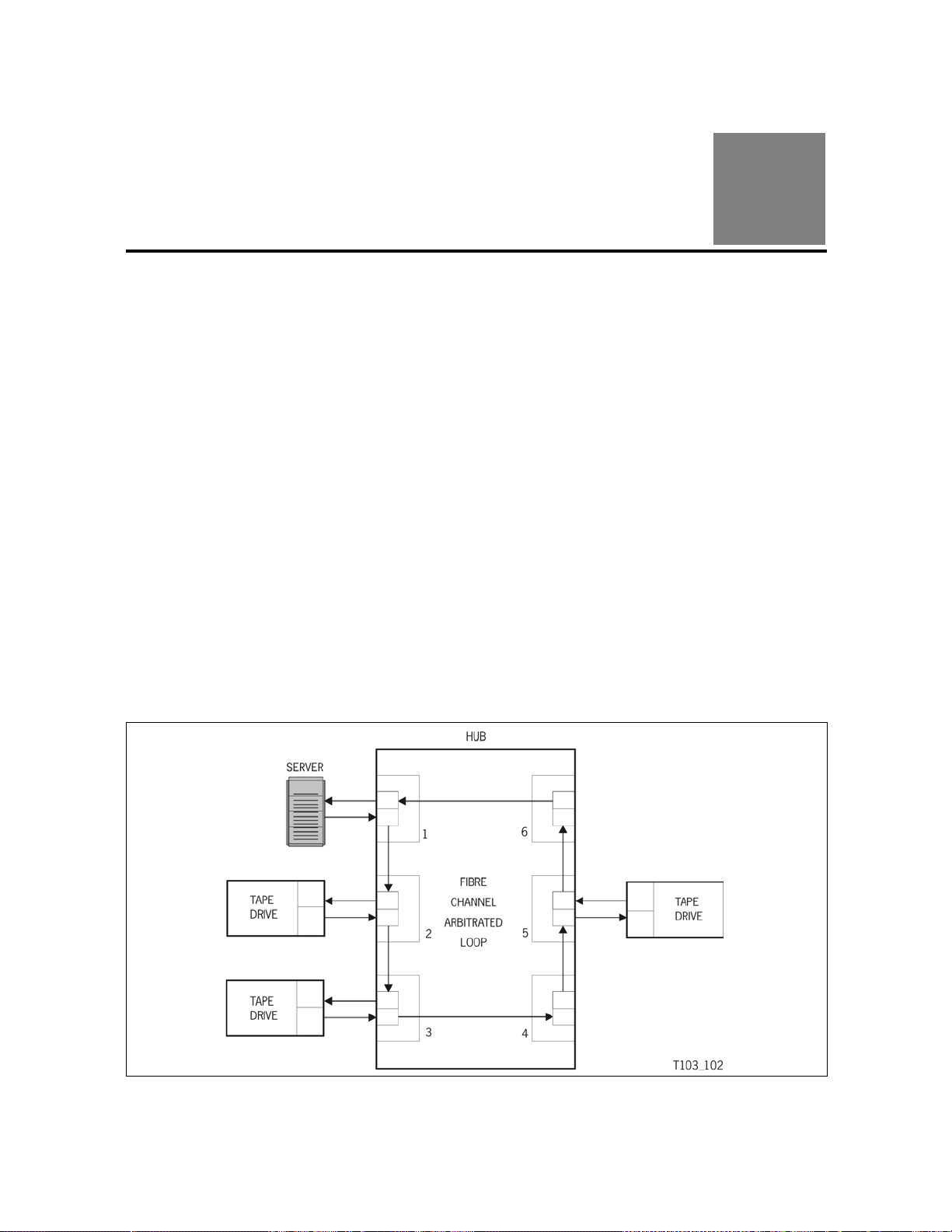
■ Arbitrated Loop
2
Figure 3 is an example of a hub producing an arbitrated loop.
Figure 3. Arbitrated Loop
E20425-01 • 9

Hubs
■ Hubs
Because of the fast growth and the increase in demand of fibre channel
attachments, hubs can provide cascading (multiple) loops within a fibre
channel network. StorageTek tape drives are designed to use hubs to provide
for an arbitrated loop which provides the following capabilities:
• Centralizes the attachment of the tape drives within the arbitrated loop
• Establishes connections with either copper or fiber optic cables
• Provides translation of physical media (such as copper to optical fiber)
• Provides an external power supply for the port bypass
• Provides port bypass functionality for port failures
• Allows cascading to increase tape drive and initiator attachment
• Supports the ability to power-on and -off, install or de-install tape drives
• Creates a central point of port management and monitoring of the drives
• Extends the distances between tape drives and initiators
■ Giga-Bit Interface Converters
Hubs use Giga-bit Interface Converters (GBICs) to provide the physical
connection to the tape drives.
GBICs connectors are available for:
• High speed serial data (HSSDC)
• Copper, 9-pin shielded “D” (DB9)
• Shortwave non-OFC
• Longwave laser
These GBICs comply with ANSI Fibre Channel physical layer requirements.
■ Considerations
Jitter is a consideration when selecting, installing, and configuring hubs within
a Fibre Channel network. Jitter is the deviation of timing of an exchange.
The accumulation of jitter occurs and continues to grow within a chain of
repeaters. As a signal is input to a repeater , jitter is not removed from the clo ck
and is transferred to the data at the output. At some level within the network,
jitter could exceed the allowable limit causing excessive errors. Assuring that
there are NL_Ports within the loop to reclock the signal, jitter will be minimized.
Loop Port State Machines (LPSM) are required to control the operation of the
loop and ensure Loop Initialization Protocol (LIP) is executed whenever a
reset or power-on occurs.
10 T10000: Interface Reference Manual • January 2011 • E20425-01

Limitations
N_Port
F_Port
There is no limit to cascading the number of hubs within a network as long as
the following guidelines are followed:
Note: Refer to the hub manufacturer’s requirements for cascading, the
• The length of the cable affects the number of allowable ports.
• The hub adds length to the cabling in the network.
• Use ports 1 and 4 to cascade to other hubs. This increases the p otential of
• Do not exceed the maximum number of hubs per cascade link.
• Configure the loop so the devices are properly positioned in relation to the
Considerations
following are just general guidelines.
dual port devices and redundant paths.
The maximum number of hubs before retiming is six (6) with short cables,
two (2) with maximum length cascade cables.
hub. Figure 4 is an example of cascading hubs.
Figure 4. Loop Containing a Switch and a Hub
E20425-01 • Chapter 2 Physical Interface 11

Considerations
Figure 5. Cascading Hubs
12 T10000: Interface Reference Manual • January 2011 • E20425-01

Redundant Paths
The tape drive interface cards are dual port to support redundant paths.
Figure 4 is an example of one server using hubs to provide redundant p aths to
the same device.
Figure 6. Redundant Paths
Cables and Connectors
■ Cables and Connectors
Because the link to a port can be driven either optically or electrically, the term
“fibre” in Fibre Channel refers to either a fiber optic or a copper cable.
• Optical transmission occurs over both single and multi–mode fibers using
both laser and light emitting diodes (LEDs) for both short (770–850 nm)
and long (1300–1360 nm) wavelengths.
• Electrical transmissions occur over video coax, miniature coax, twin coax
(Twin Ax), or twisted pair.
Note: The two types of links, either fiber optic and/or copper, can be
integrated into a single network, as long as there is a Fabric, hub, or
other type of converter present.
Cable Guidelines
Guidelines for 1 Gb cable lengths and hubs per cascade include:
• Minimum cable length is 2 m (6.5 ft)
• Maximum cable length depends on the type of connection:
- Copper = 13 m (42.6 ft) intra-cabinet
- Copper = 33 m (108 ft) inter-cabinet
- Short-wave fiber optics = 500 m (1,640 ft)
- Long-wave fiber optics = 10 kilometers (6.2 miles)
E20425-01 • Chapter 2 Physical Interface 13

Cables and Connectors
C53566
100-SM- LL-L
Distance
L long
I intermedia te
S short
Sp eed
400 400 MB ps “Qu adruple -spee d”
200 200 MB ps “Dou ble-sp eed”
100 100 MB ps “Fu ll-sp eed ”
50 50 MBps “Half-spee d”
25 25 MBps “Quarter-sp eed”
12 12 MBps “Eig hth-spee d”
Media
SM single-mode fiber
M5 mu lti-mod e ( 50 µm)
M6 mu lti-mod e (62 .5 µm)
TV video cable
MI miniature coax cable
TP tw i sted pair
Transmitter
L L lon g wa ve la se r (1,3 0 0 nm)
SL short wave laser with OFC (780 nm)
SN
LE long wave LE D
EL electrical
short wav e lase r without O FC (780 nm)
Distance
L long
I intermediate
S short
V very long
Interface Ports
The T10000 tape drive can support either short or long wavelength interface
ports. The tape drive is designed to accept the small form-factor pluggable
(SFP) transceivers in to the interface ports. It is acceptable to use one port as
short wave and one port as long wave (mixed).
Table 8 and Figure 7 list the cable and connector specifications.
Table 8. Cable Specifications
Data Rate Distance
(maximum)
FC-0 Code Cable Type Connector
Meters Feet
1.062 Gb/s 500 1,640 100-M5-SN-I Multimode 850 nm Short wave Duplex LC
2.125 Gb/s 300 984 200-M5-SN-I Multimode 850 nm Short wave Duplex LC
4.250 Gb/s 150 492 400-M5-SN-I Multimode 850 nm Short wave Duplex LC
1.062 Gb/s 10,000 32,808 100-SM-LC-L Single mode 1300 nm Long wave Duplex LC
2.125 Gb/s 10,000 32,808 200-SM-LC-L Single mode 1300 nm Long wave Duplex LC
4.250 Gb/s 10,000 32,808 400-SM-LC-L Single mode 1300 nm Long wave Duplex LC
Figure 7 provides a description of the FC-0 codes.
Figure 7. Cable Marking Descriptions
14 T10000: Interface Reference Manual • January 2011 • E20425-01

Operations
This chapter describes how StorageTek tape drives operate using a Fibre
Channel (FC) interface.
Note: This document is defined by the requirements in FC-Tape
Revision 1.17. As updates occur to the FC-Tape document, this
document will be updated accordingly.
■ Connections
The T10000 tape drives support connections for both:
• 2FC = Direct N_Port, Arbitrated Loop, and a Fabric
• 4FC = Direct N_Port and a Fabric
Arbitrated Loop
An arbitrated loop provides multiple connections for devices that share a single
loop, but only provides point-to-point connections between an initiator and
target during communications.
3
Note: Both public loops and private loops are supported.
As with SCSI protocol, when devices want to communicate on the bus, they
must arbitrate and win the connection before communications can begin. The
same goes with the arbitrated loop. Once a device is powered-on and
initialized on the loop, it must arbitrate and win to be able to communicate with
other devices on the loop.
Fabric Attachment
Fabric, or F_Ports, provide “direct” attachments to the tape drives. The Fabric
receives frames from a source N_Port and routes them to a destination N_Port
whose address identifier is specified within the frame.
E20425-01 • 15

Direct N_Port Attachment
■ Direct N_Port Attachment
The T10000 tape drives support direct attachment to a host through a host bus
adapter (HBA) that creates an N-Port. The HBA sends and receives to and
from the tape drive.
■ Addressing
StorageTek tape drives use: Port name, Node name, and Port ID for login
validation. The StorageTek registration ID is 24 bits consisting of:
• 00104F (hex)
Table 9 indicates the Institute of Electrical and Electronics Engineers (IEEE)
registered format for Name Address Authority (NAA), company ID, and ve ndor
specific identifier for a total of 64 bits.
Table 9. Addressing Scheme
Most Significant Bit Least Significant Bit
63 60 59 36 35 00
NAA IEEE Company ID Vendor Specific Identifier
“0101” (b) 00 10 4F (hex) (to be assign e d)
All ports validate the logins by comparing Port Name, Node Name, and Port
ID. All three identifiers must match or this indicates the configuration has
changed and requires a Logout (LOGO).
Note: A LOGO terminates all open Exchanges between SCSI initiator and
target.
16 T10000: Interface Reference Manual • January 2011 • E20425-01

■ Terms and Definitions
Tables throughout this chapter use the following terms for compliance with the
American National Standards Institute (ANSI) Fibre Channel Tape (FC–Tape)
Technical Report for the StorageTek implementation.
FC–Tape Terms
Allowed (A) Can be used between an initiator and a target (tape drive). For tape
drives, this is typically dependent on the particular feature or
parameter and its applicability to the request from an initiator.
Invokable (I) Can be used between an initiator and a target. Such as if a feature
is invoked
or parameter.
Prohibited (P) Can not be used between an initiator and a target.
Required (R) Must be used between an initiator and a target. Both the initiator
a
nd target must implement the feature or parameter.
Dash (–) Indicates this parameter is not meaningful.
, the recipient must implement and respond to the feature
Terms and Definitions
Blank ( ) A blank entry indicates that the featur
Initiator SCSI device that orig
Target SCSI device that receives commands.
StorageTek Terms
Yes (Y) The StorageTek tape drive conforms to that comma nd,
No (N) The StorageTek tape drive does no
Originate (Orig.) Originates the exchange or SCSI command from the tape
Response (Resp.) Responds with an acknowledgement (R_RDY and/or
Transmission Word A four byte character containing 32 bits of information.
Word B yt e 0 Byte 1 Byte 2 Byt e 3
e is not part of the feature set.
inates commands.
feature, or value.
t conform to that
command, feature, or value.
dr
ives.
da
ta) from the tape drives.
This
is the smallest information unit transmitted on Fibre
Channel.
n(MSB) Bits (LSB)
31 24 23 16 15 8 7 0
E20425-01 • Chapter 3 Operations 17

Loop Initialization Features
■ Loop Initialization Features
Arbitrated loop initialization protocol assigns up to a possible 126 addresses to
different ports on the loop and builds a map of these addresses. The following
pages describe some loop initialization features StorageTek tape drives
perform.
Loop initialization must occur before operations on the loop can begin. The
Loop Initialization Primitive (LIP) sequence is a series of initialization frames
that establish NL_Ports on the loop.
Any NL_Port on the loop is capable of starting an initialization sequence by
transmitting LIP. When the next NL_Port detects the LIP sequence, it
retransmits it to the next NL_Port until the LIP sequence travels around the
loop to the NL_Port initiating the sequence. During loop initialization, NL_Port
addresses (AL_PA) are assigned (x’01’ to x’EF’).
NL_Port addresses (AL_PA) can be either hard (hardware assigned) or soft
(system assigned) during loop initialization.
NL_Ports attempt to establish their previous acquired address before
attempting to acquire another address when that NL_Port is powered-on or
experiences a power-on reset, recognizes a LIP (AL_PD or AL_PS) for that
port, or any other event that causes the NL_Port to lose communications.
Note: StorageTek tape drives may use a hard assigned address and attempt
to regain that address during loop initialization. If unable to obtain that
address, the tape drives accept soft addresses by the system.
Acquiring Addresses
When an NL_Port enters the loop (such as a power-on), it begin s init ializat ion
to acquire an address and to notify other ports there is a change in
configuration.
Note: If there is an exchange in process when a LIP begins, that exchange is
disrupted and possible frame corruption could occur and result in a
ULP timeout.
• If the NL_Port does not have a valid address, it begins the initialization
sequence with LIP(F7,F7).
• If the NL_Port has a valid address, it begins initialization with LIP
(F7,AL_PS).
18 T10000: Interface Reference Manual • January 2011 • E20425-01

Selective Reset
Selective resets perform a reset on the receiving port. These resets are help ful
for error recovery or reconfiguration of the loop. Any NL_Port that uses a
selective reset transmits a LIP(AL_PD,AL_PS).
• AL_PD field contains the address of the port being reset
• AL_PS contains the address of the port issuing the reset
Loop Failures
A loop failure is any of the following:
• A loss of Signal
• A loss of Synchronization for longer than R_T_TOV
If a Loop Failure occurs, the L_Port which detects the failure issues a
LIP(F8,AL_PS) if it has a valid AL_PA, or LIP(F8,F7) if it doesn’t.
Open Initializing State
Loop Initialization Features
The open initializing (OPEN-INIT) state performs the process of loop
initialization. When ports are in this state, initialization frames are transmitted
and received to identify the temporary loop master and to assign AL_PA
values. Entering this state assumes the loop is operational and sets the
Available BB_Credit equal to zero (0).
Loop Initialization Select Master
StorageTek tape drives support the process of selecting a Loop Initialization
Select Master (LISM) by using the device with the lowest PORT_NAME.
Note: If an FL_Port (fabric loop attachment) is present, it assumes t he role of
LISM.
Loop Initialization Fabric Assigned Address
StorageTek tape drives support the process of Loop Initialization Fabric
Assigned (LIFA) addresses. This process is supported when the tape drive is
operating in Public Loop mode.
Loop Initialization Previously Acquired
StorageTek tape drives support the process of Loop Initialization Previously
Acquired (LIP A) addresses. This process is supported when the t ape drive has
previously acquired an address.
E20425-01 • Chapter 3 Operations 19

Loop Initialization Features
Loop Initialization Hard Assigned
StorageTek tape drives support the process of Loop Initialization Hard
Assigned (LIHA) addresses. This process is supported when the tape drive is
first powered on and a configuration parameter enables it.
Loop Initialization Soft Assigned
StorageTek tape drives support the process of Loop Initialization Soft
Assigned (LISA) addresses. This process is supported when the hard
assigned address has been used by a different device or hard assigned
addressing is disabled.
Loop Initialization Report Position
StorageTek tape drives support the mapping process to build a map of the
AL_PA values according to their position on the loop. The temporary loop
master begins the procedure to create a Loop Initialization Report (LIRP).
This initialization report and map is done by using a 1-word frame identifier
with an offset value of one (1). As the frame is transmitted around the loop , the
next NL_Port increments the offset by a value of one and stores the
information in the AL_PA map.
Loop Initialization Loop Position
StorageTek tape drives support the process of Loop Initialization Loop Position
(LILP) by retransmitting this sequence when required.
Failure to Obtain a Loop Address
If an NL_Port is unable to obtain an address (fabric assigned, previously
assigned, hard assigned, or soft assigned) it goes into a non-participating
mode and immediately implicitly logs out all logged in ports.
If an NL_Port experiences a power-on reset, or recognizes a
LIP(AL_PD,AL_PS) it is not required to retain a previously acquired address to
use during the next loop initialization.
Private Loop Initialization Completion
At this point in loop initialization a private loop tape device has completed
initialization. It has acquired a private loop address of “00 00 xx.” The xx is its
assigned AL_PA.
The tape drive now waits for initiators, on this loop only, to complete a Port
Login (PLOGI), a Process Login (PRLI), and then to start executing tape
commands.
20 T10000: Interface Reference Manual • January 2011 • E20425-01

Public Loop Initialization Completion
The public loop tape device has now acquired a loop address of “00 00 xx” at
this point in initialization, where xx is its assigned AL_PA.
Next the tape drive will attempt a Fabric Login (FLOGI) with the loop FL_Port. If
the login is not successful, the tape drive will revert back to private loop
operation, see the Private Loop Initialization Completion description.
With the successful completion of the FLOGI, the tape drive has now acquired
its public loop address “DD AA xx.” Where DD is the fabric domain, AA is the
fabric area, and xx is the AL_PA.
The tape drive then attempts to Port Login (PLOGI) with the fabric directory
server to register with an RFC-4 request with the name service.
The tape drive now waits for initiators, on either this loop or fabric attached, to
complete a Port Login (PLOGI), a Process Login (PRLI), and then to start
executing tape commands.
Fabric F_PORT Attachment Initialization
Loop Initialization Features
In the absence of a loop environment the StorageTek tape drives will attempt to
initialize with a fabric. This is accomplished by doing a Fabric Login (FLOGI).
The FLOGI process will be attempted in each class of service that the tape drive
supports.
Once the FLOGI process is successful the tape drive will attempt to login
(PLOGI) with the fabric attached name server, if it exists. This process allows
the tape device to register its presence with the name server such that other
initiators may query the name server to find target tape drives to use.
The tape drive now waits for initiators on the fabric to complete a Port Login
(PLOGI), a Process Login (PRLI), and then to start executing tape commands.
E20425-01 • Chapter 3 Operations 21

Loop Initialization Features
Tape Drive States
Power Up
When the drive completes the power-on process both of the FC ports will be
enabled and will attempt to initialize on the attached FC topology.
When the drive completes the power-on process the LUN will be online and
capable of tape operations.
Offline
When the LUN is set to offline from the drive’s menu system, the state of the
Fibre Channel ports are not affected.
Commands like Inquiry that do not require the LUN to be online will still
execute normally.
For all other commands that require the LUN to be online, they will get a
Check Condition status. The Sense Key will be 5.
The ASC/ASCQ will be 0x2500.
Online
When the LUN is set to online from the drive’s menu system, the state of the
Fibre Channel ports are not affected. All commands may now be executed
with the LUN.
Power Down
In the process of powering down the drive, the Fibre Channel Protocol chip s will
lose power. The hub port bypasses will be activated.
Caution:
By powering down a drive, operations on these ports and/or other
ports on the loop may be adversely affected.
22 T10000: Interface Reference Manual • January 2011 • E20425-01

Arbitrated Loop Feature Set
■ Arbitrated Loop Feature Set
StorageTek tape drives implement the following Fibre Channel feature set:
Table 10. FC-AL Feature Set
Feature FC-TAPE StorageTek Notes
Initiator Target
Attempt to acquire Hard Address during LIHA
sequence of loop initialization following loss of
power, power-on reset, or recognition of LIP
(AL_PD or AL_PS)
LILP/LIRP:
Loop Master can originate
Non-loop Master L_Ports accept
Login_BB_Credit:
Advertise Login_BB_Credit = 0
Advertise Login_BB_Credit > 0
Accept Login_BB_Credit = 0
Accept Login_BB_Credit > 0
LPEyx/LPByx/LPEfx (origination) A P N 2
MRKtx (origination) P P N 3
Open Full Duplex - OPN(yx):
Open Originator can send
Open Recipient accepts
RR Y 4
R
R
A
A
R
R
I
R
R
R
A
A
R
R
I
R
Y
Y
Y
N
Y
Y1
N
Y5
Open Half Duplex - OPN(yy):
Open Originator can send
Open Recipient accepts
Open Multicast/Selective Replicate
OPN(yr), OPN(fr):
Open Originator
Notes:
I
R
PP N
I
R
Y
Y
1. The actual value is between 0 and the LOGIN_BB_Credit.
2. LPEfx is useful for resetting bypass circuits of NL_Ports which have lost their address.
3. Any NL_Port receiving an MRK attempts to forward it, StorageTek does not originate it.
4. This feature may be disabled by a configuration item change.
5. Our target will accept the Open Full Duplex but the FCP simplex protocol does not take
advantage of the full duplex capabilities.
E20425-01 • Chapter 3 Operations 23

Arbitrated Loop Feature Set
Login_BB_Credit Equals Zero
StorageTek tape drives advertise Login_BB_Credit =0. When
Login_BB_Credit=0 at the other L_Port, the following rules apply:
• The OPN originator must receive R_RDYs (receiver readys) from the tape
drive before transmitting a frame.
• The OPNed responder transmits R_RDYs for the number of buffers
available to receive frames.
Note: OPN Originators open as either full or half duplex regardless of the
value of the Login_BB_Credit.
Open and Close Latencies
When Login_BB_Credit=0, a latency exists while waiting for the t ape drives to
respond with two (2) R_RDYs. This exists for every OPN before frame
transmission can begin.
To improve the latencies 2-4 and 3-5, and StorageTek tape drives immediately
respond with at least 2 and as many as 5(depending on drive) R_RDYs on an
OPN. This is controlled by a configuration item.
Some NL_Ports reduce CLS latency in another way:
To prevent buffer overruns, a CLS Recipient is only required to have maximum
Login_BB_Credit, granted to any L_Port buffers, available before receiving the
next OPN.
24 T10000: Interface Reference Manual • January 2011 • E20425-01

Common Service Parameters
■ Common Service Parameters
Table 11 lists the Common Service Parameters for Port Login (PLOGI):
Table 11. NL_Port Common Service Parameters, Port Login
Parameter Word Bits StorageTek Value FC-Tape
2FC
N_Port
2FC
NL_Port
4FC
N_Port
FC-PH Version:
Highest Version
Lowest Version
Buffer-to-Buffer Credit (min.) 0 15–0 x’0003’ x’0000’ x’025A’
0
0
31–24
23–16
x ‘09’
x ‘09’
x ‘09’
x ‘09’
x ‘20’
x ‘20’
x’0003’
x ‘20’
1
2
Common Features: 1 31–16
Continuously Increasing Relative
1311 1 1 1
Offset
Random Relative Offset 1 30 0 0 0 0
Valid Vendor Version Level 1 29 0 0 0 0
N_Port/F_Port 1 28 0 0 0 0
Alternate BB_Credit Management 1 27 1 1 1 –
E_D_TOV Resolution 1 26 0 0 0 –
Reserved 1 25–23 0 0 0 –
Dedicated Simplex 1 22 0 0 0 –
x
0
Reserved 1 21–19 0 0 0 –
Dynamic Half Duplex – DHD 1 18 0 0 0 –
SEQ_CNT 1 17 0 0 0 x
Payload Length 1 16 0 0 0 –
Buffer-to-Buffer Receive Data
1 15–0 x’0800’ x’0800’ x’0800’ 256
Field Size (min.)
T otal Concurrent Sequences (min.) 2 31–16 x’00FF’ x’00FF’ x’00FF’ 1
Relative Offset by Information
2 15–0 x‘000F x‘000F x‘001F’ x‘0002
Category = (Category 1 and 5 only)
Error Detect Timeout (E_D_TOV)
3 31–0 x‘000007D0’ x‘000007D0’
2 seconds
1. With inline credit extender enabled.
2. With inline credit extender disabled.
E20425-01 • Chapter 3 Operations 25

Common Service Parameters
Table 12 lists the Common Service Parameters the tape drive supports for
Fabric Login (FLOGI):
Table 12. NL_Port Common Service Parameters, Fab ric Lo gin
Parameter Word Bits StorageTek Value NL-Port
Originator
x
x ‘20’
FC-PH Version:
Highest Version
Lowest Version
2FC
N_Port
0
0
31–24
23–16
x ‘09’
x ‘09’
2FC
NL_Port
x ‘09’
x ‘09’
4FC
N_Port
x ‘20’
x ‘20’
Buffer-to-Buffer Credit (min.) 0 15–0 x’0003’ x’0000’ x’025A’
x’0003’
1
2
Common Features:
Reserved 1 31–30 0 0 0 –
Valid Vendor Version Level 1 29 0 0 0 0
N_Port/F_Port 1 28 0 0 0 0
Alternate BB_Credit Management 1 27 0 1 0 1
Reserved 1 26–19 0 0 0 –
Dynamic Half Duplex 1 18 0 0 0 –
Reserved 1 17 0 0 0 –
Payload Length 1 16 0 0 0 –
Buffer-to-Buffer Receive Data
1 15–0 x‘0800’ x‘0800’ x‘0800’ 256
Field Size (min., see note)
Reserved 2 31–0 0 0 0 –
Reserved 3 31–0 0 0 0 –
Note: This is controlled by a configuration item.
–
1. With inline credit extender enabled. ?
2. With inline credit extender disabled.
26 T10000: Interface Reference Manual • January 2011 • E20425-01

FC Class 3
■ FC Class 3
Fibre Channel provides several different strategies to ensure reliable
communications between devices. These strategies are called Classes of
Service. The tape drive supports the Class 3 level of service which provides
no notification of frame delivery or non-delivery. This class of service reduces
the number of frames (traffic) on the loop.
The start-of-frame (SOF) delimiter specifies the type of service used for each
frame during communications.
Table 13 indicates the two types of delimiters for Class 3 operations.
Table 13. Start of Frame Delimiters, Class 3
Delimiter Abbreviation Transmission Word Characters
SOF Initiate Class 3 SOFi3 K28.5 D21.5 D22.2 D22.2
SOF Normal Class 3 SOFn3 K28.5 D21.5 D22.1 D22.1
Note: Intermixing different classes of service is not supported.
The tape drives adhere to a set of operating characteristics that insure inter-
operability and reliability within a Class 3 loop environment is maintained.
Table 14 and Table 15 list Class 3 Service Parameters supported.
Class 3 Service Parameters, Port Login
Table 14 lists Class 3 Service Parameters for Port Login (PLOGI):
Table 14. Class 3 Service Paramete rs, Port L og in
Parameters Word Bits StorageTek Value FC-
2FC
N_Port
Class validity 0 31 1 1 1 1
Service Options: 0 30–16
Intermix Mode 0 30 0 0 0 –
Stacked Connect Requests 0 29–28 00 00 00 –
Sequential Delivery 0 27 0 0 0 –
Dedicated Simplex 0 26 0 0 0 –
2FC
NL_Port
4FC
N_Port
Tape
Camp-On 0 25 0 0 0 –
Buffered Class 1 0 24 0 0 0 –
Priority 0 23 0 0 0 –
E20425-01 • Chapter 3 Operations 27

FC Class 3
Table 14. Class 3 Service Parameters, Po rt L ogin (Conti nu ed)
Parameters Word Bits StorageTek Value FC-
Tape
Initiator Control: 0 15–0
2FC
N_Port
2FC
NL_Port
4FC
N_Port
Sequence Initiator X_ID
0 15–14 00 00 00 –
reassignment
Initial Responder Process_Associator 0 13–12 00 00 00 00
Sequence Initiator ACK_0 capable 0 11 0 0 0 –
Sequence Initiator ACK_N Capable 0 10 0 0 0 –
ACK generation assistance 0 9 0 0 0 –
Initiator Data compression capable 0 8 0 0 0 0
Initiator Data compression history
0 7–6 00 00 00 –
buffer size = ‘00’b
Data Encryption Capable 0 5 0 0 0 0
Clock Synchronization Capable 0 4 0 0 0 P
Recipient Control: 1 31–16
ACK_0 Capable 1 31 0 0 0 –
ACK_N Capable 1 30 0 0 0 –
X_ID Interlock 1 29 0 0 0 –
Error Policy Supported 1 28–27 00 00 00 TBD
Categories per Sequence 1 25–24 00 00 00 00
Data compression capable 1 23 0 0 0 0
Data compression history buffer size 1 22–21 00 00 00 –
Data decryption capable 1 20 0 0 0 0
Clock synchronization capable 1 19 0 0 0 A
Reserved – fabric specific 1 18–16 0 0 0 0
Receive data field size (min.) 1 15–0 x‘0800’ x‘0800’ x‘0800’ 256
Concurrent Sequences > 0 2 31–16 x‘00FF’ x‘00FF’ x‘00FF’ 1
N_Port End-to-end Credit 2 14–0 0 0 0 –
Open Sequences per Exchange > 0 3 31–16 x‘0001’ x‘0001’ x‘0001’ 1
Class 6 Multicast RX_ID 3 15–0 0 0 0 –
28 T10000: Interface Reference Manual • January 2011 • E20425-01

FC Class 3
Class 3 Service Parameters, Fabric Login
Table 15 lists Class 3 Service Parameters the tape drives support for Fabric
Login (FLOGI):
Table 15. Class 3 Service Parameters, Fabric Login
Parameters Word Bits StorageTek Value FC-
2FC
N_Port
Class validity 0 31 1 1 1 1
Service Options:
Intermix Mode 0 30 0 0 0 –
Stacked Connect Requests 0 29–28 0 0 0 –
Sequential Delivery 0 27 1 1 1 1
Dedicated Simplex 0 26 0 0 0 –
2FC
NL_Port
4FC
N_Port
Tape
Camp-On 0 25 0 0 0 –
Buffered Class 1 0 24 0 0 0 –
Reserved 0 23 0 0 0 –
Initiator Control:
Reserved 0 15–0 00 00 00 –
Recipient Control:
Reserved 1 31–16 0 0 0 –
Receive data field size (min, see note) 1 15–0 x‘0800’ x‘0800’ x‘0800’ 256
Concurrent Sequences (min) 2 31–16 0 0 0 –
N_Port End-to-end Credit 2 14–0 0 0 0 –
Open Sequences per Exchange (min) 3 31–16 0 0 0 –
Reserved 3 15-0 0 0 0 –
Note: This is controlled by a configuration item.
E20425-01 • Chapter 3 Operations 29

FC-2 Features
■ FC-2 Features
The FC-2 level provides the signaling protocol and specifies the rules and
requirements to transfer blocks of data.
The FC-2 level is the most complex level in Fibre Channel protocols and
provides the different classes of service, packetizing, sequencing, error
detection, and reassembling the transmitted data.
Table 16 lists other FC-2 features supported by the tape drive:
Table 16. Other FC-2 Features
Feature
Initiator Target
Addressing Scheme: (see note)
Node Name Format (registered format) R R Y
Port Name Format (registered format) R R Y
Frame Control (F_CTL):
Continue Sequence Condition R R Y
Continuously increasing sequence count during
consecutive sequences within an Exchange
Ignore nonzero Continue Sequence values A A Y
Sequence Chaining (C_S bit in F_CTL = 0) R R Y
Optional Headers (all) P P N
Routing Control (R_CTL):
FC-4 Device_Data frame RRY
Extended Link_Data frame R R Y
FC-Tape
RRY
StorageTek
FC-4 Link_Data Frame R R Y
Video_Data Frame P P N
Basic Link_Data frame R R Y
Link_Control frame
Class 3 R R Y
Class 2 P P N
X_ID Interlock – – N
Note: Node name and Port name are not identical.
30 T10000: Interface Reference Manual • January 2011 • E20425-01

■ Link Service Commands
Fibre Channel uses link service commands to manage functions such as port
management, Login, Logout, and abort operations. The tape drives support
both basic and extended link service commands to perform these operations.
Basic Commands
Table 17 lists the Basic Link Service commands:
Table 17. Basic Link Services
Command FC-TAPE StorageTek
Link Service Commands
From
Initiator
No Operation (NOP) P – P – N
Abort Sequence (ABTS) I R A Y Y
Basic Accept (BA_ACC) A R – Y
Basic Reject (BA_RJT) A R – Y
Dedicated Connection Pre-empted
(PRMT)
Remove Connection (RMC) Class 1 P – P – N
P–P–N
Target
Response
From
Target
Drv
Orig.
Drv
Resp.
E20425-01 • Chapter 3 Operations 31

Link Service Commands
Extended Commands
Table 18 lists the Extended Link Service commands:
Note: If the tape drive receives a request for Extended Link Services which
are not supported, the tape drive returns a Link Services Command
Reject (LS_RJT) with a reason code of “Command Not Supported”.
Table 18. Extended Link Services
Command FC-TAPE StorageTek
From
Initiator
Abort Exchange (ABTX) P P N –
Accept (ACC) A R Y Y
Advise Credit (ADVC) P P N –
Discover Address (ADISC) I R P N Y
Discover F_Port
Parameters (FDISC)
Discover N_Port
Parameters (PDISC)
Echo P P N–
Establish Streaming
(ESTS)
Estimate Credit (ESTC) P P N –
Fabric Activate Alias_ID
(FACT)
Fabric Address Notification
(FAN)
I I N–
IRP –Y
P P N–
P P N–
PPPPN–
Target
Response
From
Target
Initiator
Response
Drv
Orig.
Drv
Resp.
Fabric Deactivate Alias_ID
(FDACT)
Fabric Login (FLOGI) R P R P Y –
Get Alias_ID (GAID) P P N –
Link Service Reject
(LS__RJT)
Logout (LOGO) R R R R Y Y
Loop Initialize (LINIT) I P N Y
Loop Port Control (LPC) I P N N
32 T10000: Interface Reference Manual • January 2011 • E20425-01
P P N–
ARYY

Link Service Commands
Table 18. Extended Link Services (Continued)
Command FC-TAPE StorageTek
From
Initiator
Target
Response
From
Target
Initiator
Response
Drv
Orig.
Drv
Resp.
Loop Status (LSTS) I P N N
N_Port Activate Alias_ID
P P N–
(NACT)
N_Port Deactivate
P P N–
Alias_ID (NDACT)
N_Port Login (PLOGI) R R P N Y
Process Login: (PRLI) R R P N Y
PRLI Common Service
P–P NN
Parameters
Single Service
RRP NY
Parameter page per
request
Multiple Service
P–P NN
Parameter pages per
request
ACC contains only
–RP NY
those pages specified
Accept Response code
–RP NY
of Command executed
Process Logout (PRLO) I R I R Y Y
Quality of Service Request
P P N–
(QoSR)
Read Connection Status
P P N–
Block (RCS)
Read Exchange Concise
RR AAYY
(REC)
Read Exchange Status
PPN–
Block (RES)
Read Link Error Status
IRP NY
Block (RLS)
Request Sequence
AAAATBDTBD
Initiative (RSI)
Read Sequence Status
AAAATBDTBD
Block (RSS)
E20425-01 • Chapter 3 Operations 33

Link Service Commands
Table 18. Extended Link Services (Continued)
Command FC-TAPE StorageTek
From
Initiator
Read Timeout V alue (RTV) P P N –
Read VC Status (RVCS) P P N –
Reinstate Recovery
Qualifier (RRQ)
Registered State Change
Notification (RSCN)
Report Node Capabilities
(RNC)
State Change Notification
(SCN)
State Change Registration
(SCR)
Test P P N –
Test Process Login State P P N –
Third Party Process
Logout (TPRLO)
IRIRYY
IRIRNY
IRP NY
PPN–
IPIPNN
IRP NY
Target
Response
From
Target
Initiator
Response
Drv
Orig.
Drv
Resp.
Table 19. FC-4 Link Services
Command FC-TAPE StorageTek
From
Initiator
Sequence
Retransmission Request
(SRR)
Target
Response
IRP NY
From
Target
Initiator
Response
Drv
Orig.
Drv
Resp.
34 T10000: Interface Reference Manual • January 2011 • E20425-01

Responses to Link Services
Table 20 summarizes the response the tape drives generate when receiving
different Link Service requests when the drive NL_Port is n ot currently logged
in with the sending Port.
Table 20. Response to Link Services from Ports Not Logged-In
Link Service Commands
Frame
Received
ABTS Discard and send LOGO BA_ACC, BA_RJT 2
ADISC Discard and send LOGO ACC and LS_RJT 1
FAN Process the ELS request, no
LOGO ACC ACC
PDISC Discard and send LOGO ACC and LS_RJT 1
PLOGI ACC, LS_RJT ACC
PRLI Discard and send LOGO ACC
PRLO Discard and send LOGO ACC and LS_RJT 3
RSCN Process the ELS request, no
Other Link
Services
Notes:
8. All three identifiers must match at login for Accepts (ACC) to be returned:
Port Not Logged In Port Logged In Notes
Process the ELS request, no
response required
response required.
Discard and send LOGO ACC and LS_RJT
response required.
Process the ELS request, no
response required.
• Port ID,
• Port Name, and
• Node Name
If all three identifiers do not match a logout (LOGO) is returned.
If other conditions prevent execution of the ADISC or PDICS ELS, return a reject (LS_RJT) with
the appropriate reason code.
9. BA_ACC if valid RX_ID else BA_RJT
10. If PRLI has not been successfully completed, set the reason code to
“Image Pair Does Not Exist.”
E20425-01 • Chapter 3 Operations 35

Frame Transmission
C53567
Idles
S
O
F
Fra m e
Header
Data Field
(Plus optional Headers)
C
R
C
E
O
F
Idles
Word
0
1
2
3
4
5
Byte 0
R_C T L
CS_CTL
Typ e
SEQ _ID
Byte 1 Byte 2
Byte 3
Destina tion_ID
So u rc e _ID
F_C T L
DF_CTL SEQ _C NT
RX_ID
OX_ID
Para mete r
■ Frame Transmission
Figure 8 shows the frame format for transmission of data and commands over
Fibre Channel.
Figure 8. Frame and Frame Header Format
R_CTL Routing Control: Indicates the type of frame functions
Destination ID
Identifies the port destination
CS_CTL Class specific control field
Source ID Identifies the source
Type Indicates the data structure
F_CTL Frame Control: Controls information within the frame
SEQ_ID Sequence Identifier: Identifies sequences within an exchange
DF_CTL Data Field Control: Indicates optional headers
SEQ_CNTSequence Count: Contains frame number within exchange
OX_ID Originator Exchange ID: Identifies originator of exchange
RX_ID Responder Exchange ID: Identifies responder of exchange
ParameterContains unique parameters for exchange
36 T10000: Interface Reference Manual • January 2011 • E20425-01

■ Exchange Management
Exchange (X) management is the overall control of operations over the Fibre
Channel interface between the originator and responder.
Refer to the FC–PH documents for rules and guidelines pertaining to Class 2
operation.
Note: For FCP, an exchange is a single SCSI command.
There are two fields in the frame header dealing with exchanges:
• OX_ID = Exchange originator
• RX_ID = Exchange responder
Table 21. Exchange Content Header
Word Byte 0 Byte 1 Byte 2 Byte 3
0 R_CTL Destination_ID
1 CS_CTL Source_ID
Exchange Management
2Type F_CTL
3 SEQ_ID DF_CTL SEQ_CNT
4 OX_ID RX_ID
5 Parameter
Exchange Originator
The exchange originator assigns a unique OX_ID to the exchange for the
transmission of in-order delivery of frames and assumes the frames are
processed in the order received. The exchange is open from the time the first
frame is sent until one of the following occurs:
• Timeout
• The exchange is aborted (ABTS or ABTX)
• An end-of-frame (EOF) delimiter is sent with the last sequence bit set
• A Logout (LOGO) is sent to or received from the Exchange responder
• A Link Service Command Reject (LS_RJT) is sent in response to an
ADISC or PDISC during target discovery
• A PLOGI is sent to the Exchange responder
E20425-01 • Chapter 3 Operations 37

Sequence Management
Exchange Responder
The exchange responders assign unique RX_ID values or use the value of
“FFFF.” The exchange responder considers an exchange open from the time it
receives the first frame of the first information unit until one of the following
occurs:
• The last frame of the last information unit is sent with the last sequence bit
set
• The exchange is aborted (ABTS)
• A Logout (LOGO) is sent to, or received from, the Exchange originator
• An LS_RJT is sent in response to an ADISC or PDISC during target
discovery
• A PLOGI is received
■ Sequence Management
Sequence management deals with the actual order and transfer of frames
across Fibre Channel. The SEQ_ID and SEQ_CNT identify the order of
frames for reassembly at the responder.
Refer to the FC–PH documents for rules and guidelines pertaining to Class 2
operation.
Table 22. Sequence Content Header
Word Byte 0 Byte 1 Byte 2 Byte 3
0 R_CTL Destination_ID
1 CS_CTL Source_ID
2Type F_CTL
3 SEQ_ID DF_CTL SEQ_CNT
4 OX_ID RX_ID
5 Parameter
38 T10000: Interface Reference Manual • January 2011 • E20425-01

Sequence Open
The tape drive considers a Sequence open from the time that the first frame of
the Sequence (the frame with the SOFi3 delimiter) is sent until one of the
following occurs:
• An end-of-frame (EOF) delimiter is sent with the last sequence bit set
• A LOGO is sent to, or received from, the Sequence responder
• The sequence is aborted with ABTS
The tape drive as a Sequence responder considers a Sequence open from the
time that the first frame of the Sequence (the frame with the SOFi3 delimiter)
is received until one of the following occurs:
• An end-of-frame (EOF) delimiter is sent with the last sequence bit set
• The Sequence is aborted using ABTS
• A LOGO is sent to, or received from, the Sequence originator
Sequence Identifier Usage
The sequence identifier (SEQ_ID) is a field in the frame header that sets one
frame apart from another indicating the order in which they occur. The
following paragraphs summarize the rules governing the reuse of SEQ_IDs.
Sequence Management
For sequences which transfer Sequence Initiative:
• A Port can reuse a SEQ_ID for the same Exchange following the
confirmation of Sequence delivery.
• A Port can reuse the SEQ_ID with a different Exchange (to the same, or a
different destination Port) immediately following transmission of the last
frame of the Sequence without waiting for confirmation of Sequence
delivery.
For sequences which do not transfer Sequence Initiative:
• Consecutive FCP_DATA Sequences for the same exchange follow the
FC-PH rules for streamed Sequences which include:
a. The first FCP_DA T A Seq uence after transfer of Sequence Initiative is
not a streamed Sequence. It can use any eligible SEQ_ID and the
SEQ_CNT can be either zero or a continuously increasing number.
b. The second and subsequent Sequences within the same exchange
are treated as streamed.
• Because frame delivery is not confirmed, the Sequence Initiator cannot
reuse a SEQ_CNT within a given Sequence.
For sequences beginning with a SEQ_CNT of zero, the SEQ_CNT cannot
wrap when reaching a hexadecimal count of “FFFF”.
For sequences beginning with a SEQ_CNT of ‘n’ (where n is not zero) the
SEQ_CNT can wrap when reaching a hexadecimal count of “FFFF” and
continue from zero up to a value of n-1.
E20425-01 • Chapter 3 Operations 39

Error Detection and Management
Sequence Errors
Sequence errors are managed as defined in FC–Tape with the following
additions:
1. If a frame with an SOFi3 delimiter is received and the SEQ_CNT is not
equal to zero or +1 from the SEQ_CNT of the last frame of the previous
Sequence of that Exchange.
2. If the SEQ_CNT of a received frame with an SOFn3 delimiter is not +1
greater than the previous frame received for that Sequence (such as a
frame was lost).
This also detects the case where a frame with an SOFn3 delimiter is
received for a SEQ_ID that is not currently open since the SEQ_CNT of
the previous frame for that Sequence is undefined.
3. If a frame with an SOFi3 delimiter is received and the previous Sequence
of that Exchange is still open.
4. If the relative offset in the parameter field of a received frame with an
SOFn3 delimiter is not equal to the (relative offset + the payload size) of
the previous frame received for that Sequence.
5. If the next frame of a Sequence is not received within E_D_TOV.
6. If, during the same Sequence Initiative, a Sequence is received which has
the same SEQ_ID as the previous Sequence of that Exchange.
When a Sequence error is detected by the tape drive, it discards that
Sequence, and all remaining Sequences for the Exchange containing the
Sequence in error. The tape drive attempts to take the appropriate action as
defined in FCP–2.
■ Error Detection and Management
Error detection falls under two categories: Frame errors and link-level errors.
• Frame errors result in missing or corrupted frames which may ultimately
involve Upper Level Protocols to resolve.
• Link-level errors include errors such as loss of signal, loss of
synchronization, and timeouts.
Upper Level Protocols (ULP) provide for error detection and management by
using timeouts which is an inefficient mechanism to detect and recover from
frame transmission errors.
FC-2 layer protocols attempt to recover from errors through transmitting
frames, Extended Link Services commands, and Primitive Sequence
protocols (as defined in FCP-2)
A problem with Class 3 operation is that there is no confirmation of frame
delivery. Although, the originator can deduce some delivery of frames from:
40 T10000: Interface Reference Manual • January 2011 • E20425-01

Error Detection and Management
• Successfully receiving a command by:
• FCP Transfer ready was sent by the command recipient
• FCP read data was received
• A response was received
• Successfully receiving write data by:
• FCP Transfer Ready was received
• A response was received
However, FCP data and FCP responses cannot always be detected.
Currently, the FCP-2 defines detection of these missing frames by using
timeouts. For FCP responses, the target may request the initiator to send an
FCP confirmation to confirm receipt of the response. Refer to FCP-2 for a
more detailed description.
Caution:
Fibre Channel provides no error correction on
provide excellent error detection schemes, including:
• 8B/10B encoding and decoding
•Disparity
• Cyclic redundancy checks
• Sequence errors and out-of-order delivery
From a tape drive standpoint, it is very important that error
detection and recovery ensure both the initiator and target are in
with block position on tape. Therefore; if the initiator suspects
sync
that the result of an error leaves the drive out of sync with the
initiator, the initiator should issue a Read Position command to
determine the location and to invoke the Upper Level Protocol
(FC-4) to reposition the tape if necessary.
8B/10B Encoding and Decoding
Fibre Channel uses a special process called encoding and decoding that is
designed to reduce distortion during transmission and aid in the detection of
errors at the receiving port. This process makes it highly likely that single and
multiple bit errors are detected.
Besides providing error detection, this process also balances the turning on
and off of the light for the loading of the optical fiber transmitters.
data during transfers but it does
The process of encoding uses an algorithm that takes the original 8 bits in
each byte and transforms them into 10 bits for transmission. The result is an
8B/10B encoding of a byte and is called a transmission character.
E20425-01 • Chapter 3 Operations 41

Error Detection and Management
Disparity
Fibre Channel uses a scheme along with the 8B/10B encoding to protect
transmission characters and aid in error detection called running disparity.
Running disparity adds a second dimension to the transmission of characters.
This dimension provides a balance of ones and zeros which helps protect
transmission characters and controls the heat output of the transmitter.
A negative running disparity is maintained following the transmission of the
end-of-frame (EOF) delimiter and remains negative until the transmission of
the next start-of-frame delimiter.
Because the running disparity within a frame is variable, two different EOF
delimiters are used depending on the content of the frame following the
transmission of the CRC.
Table 23. End of Frame Delimiters
Delimiter Abbreviation RD Transmission Word Characters
EOF Normal EOFn Neg. K28.5 D21.4 D21.6 D21.6
Pos. K28.5 D21.5 D21.6 D21.6
EOF Terminate EOFt Neg. K28.5 D21.4 D21.3 D12.3
Pos. K28.5 D21.5 D21.3 D21.3
EOF Abort EOFa Neg. K28.5 D21.4 D21.7 D21.7
Pos. K28.5 D21.5 D21.7 D21.7
EOF Normal
Invalid
EOFni Neg. K28.5 D10.4 D21.6 D21.6
Pos. K28.5 D10.5 D21.6 D21.6
CRC
Fibre Channel adds a third level of protection over the content of each frame
called a cyclic redundancy check (CRC). Each frame is protected by a 4-byte
CRC which provides a separate and independent error detection mechanism.
42 T10000: Interface Reference Manual • January 2011 • E20425-01

Fibre Channel Timers
■ Fibre Channel Timers
StorageTek’s tape drives use the timer values in Table 24.
Table 24. Timer Summary
Timer Value Implemented By
Initiator Target StorageTek
AL_TIME 15 ms R R Y
R_T_TOV 100 ms R R Y
E_D_TOV Private = 2 sec.
Public = supplied + 2 sec.
R_A_TOV
R_A_TOV
RR_TOV
RR_TOV
REC_TOV > = E_D_TOV + 1 sec. (min.) R R Y
ULP_TOV > = Operation specific timer +
Notes:
1. The division of R_A_TOV usage differs from the FC-PH because of the unique characteristics of
an Arbitrated Loop environment.
2. SCSI target devices that support Class 2 are required to implement this timer.
SEQ_QUAL
Private = 2 sec.
ELS
AUTH
SEQ_INIT
Private = 0 sec.
Public = 10 sec. (note 1)
Public = 10 sec.
2 sec. R Y
> = REC_TOV +
2 x R_A_TOV
2 x RR_TOV
+ 1 sec.
ELS
R
R
RA
RR Y
RN
2
A
R
(note 2)
RY
Y
Y
Y
Arbitrated Loop Timeout
The Arbitrated Loop timeout value (AL_TIME) is two times the worst case
round-trip latency of a very large loop.
Receiver_Transmitter Timeout
The Receiver_Transmitter timeout value (R_T_TOV) is used by the receiver
logic to detect a loop failure.
E20425-01 • Chapter 3 Operations 43

Fibre Channel Timers
Error_Detect Timeout
The Error Detect Timeout value (E_D_TOV) is the maximum time permitted
for a Sequence Initiator between the transmission of consecutive data frames
within a single sequence. This is also the minimum time that a Sequence
Recipient waits for the reception of the next frame within a single sequence
before recognizing a Sequence timeout.
E_D_TOV includes the time required to gain access to the loop in addition to
the actual frame transmission time.
Resource Allocation Timeouts
The Resource Allocation Timeout (R_A_TOV) has two components:
• Sequence Qualifiers (SEQ_QUAL) defines the minimum time that an
initiator waits before reusing the sequence qualifiers (SEQ_ID and
SEQ_CNT).
• Extended Link Services (ELS) determines the minimum time the Originator
of an extended link service request waits for the response to a request as
a target.
Resource Recovery Timeout
The Resource Recovery Timeout (RR_TOV) is the minimum time the target
waits for an initiator to perform an exchange authentication following the
completion of the loop initialization.
REC Timeout
The Read Exchange Concise Timeout value (REC_T OV) is used to time rep ly
sequences and a polling interval for REC error detection. Refer to FCP-2 for a
detailed description.
Upper Level Protocol Timeout
The Upper Level Protocol Timeout (ULP_TOV) is used by the initiator to time
the completion of exchanges associated with the ULP operations. The timeout
values vary depending on the operations being timed.
44 T10000: Interface Reference Manual • January 2011 • E20425-01

FCP Feature Set
■ FCP Feature Set
Fibre Channel Protocol (FCP) provides functions such as login and logout
parameters and the transfer of commands and data through the use of
Information Units. The FCP command set for the tape drives is SCSI-3.
Process Login Parameters
Table 25 and Table 26 on page 46 lists Process Login (PRLI) parameters
supported.
Table 25. PRLI Parameters
Feature FC-Tape StorageTek
Initiator Target
Command + Data in same Sequence (Write) = 1 P P N
Data Overlay Allowed = 1 (see note) I R Y
Data + Response in same Sequence (Read) = 1 P P N
Establish Image Pair (bit 13) = 0 I R Y
Establish Image Pair (bit 13) = 1 R R Y
SRR/REC Recovery Supported = 1 R R Y
Confirmed Completion Allowed =1 I R Y
Initiator Function =1 R A N
Originator Process Associator P P N
Originator Process Associator Valid = 1 P P N
Responder Process Associator P P N
Responder Process Associator Valid = 1 P P N
Obsolete (Read XFER_RDY Disabled) = 1 R R Y
Target Function = 1 A R Y
Write XFER_RDY Disabled = 1 P P N
If the initiator requests it, the use of data overlay is only allowed in response to an SRR
(such as error recovery).
E20425-01 • Chapter 3 Operations 45

FCP Feature Set
Table 26. PRLI Accept FCP Services Parameter Page
FCP Service Parameters Word Bits StorageTek Value
2FC
N_Port
2FC
NL_Port
4FC
N_Port
SCSI FCP (08h) 0 31–24 x’08’ x’08’ x’08’
Reserved 0 23–16 0 0 0
Originator Process_Associator Valid 0 15 0 0 0
Responder Process_Associator Valid 0 14 0 0 0
Image Pair Established 0 13 1 1 1
Reserved 0 12 0 0 0
Accept Response Code 0 11–8 b’0001’ b’0001’ b’0001’
Reserved 0 7–0 0 0 0
Originator Process_Associator 1 31–0 0 0 0
Responder Process_Associator 2 31–0 0 0 0
Reserved 3 31–10 0 0 0
Task Retry Identification Requested 3 9 1 1 1
Retry 3 8 1 1 1
Confirmed Completion Allowed 3 7 0 0 0
Data Overlay Allowed 3 6 0 0 0
Initiator Function 3 5 0 0 0
Target Function 3 4 1 1 1
Obsolete 3 3 0 0 0
Obsolete 3 2 0 0 0
Read FCP_XFER_RDY Disabled 3 1 1 1 1
Write FCP_XFER_RDY Disabled 3 0 0 0 0
46 T10000: Interface Reference Manual • January 2011 • E20425-01

■ FCP Information Units
WRITE CMD READ CMD
T1
T1
FCP_CMD
FCP_CMD
I1
I3
I3
I4
I1
I4
I5
FCP_XFER_RDY
FCP_XFER_RDY
FCP_RSP
OR
FCP_RSP
FCP_CONF
FCP_CONF
(O PTIO N AL)
(O PTIO N AL)
DATA
DATA
DATA
DATA
DATA
DATA
DATA
FCP_RSP
DATA
DATA
DATA
DATA
DATA
Single Sequence
S ingle or Multiple Sequ en ces
Single Sequence
T6
T6
T12
T12
C 53565
OR
FCP_RSP
I5
Information units transfer data to and from the SCSI Initiator and SCSI Target
and include the following required units:
• T1 = Command and Task Management
• T6 = Write Data (such as Mode Select and Write commands)
• T12 = Response Received Confirmation
• I1 = Transfer Ready on a Write Command
• I3= Read Data (such as Mode Sense and Read commands)
• I4 = Response (such as Status)
Figure 9. Examples of Read and Write Information Units
FCP Information Units
E20425-01 • Chapter 3 Operations 47

FCP Information Units
Command Information Unit
The Command Information Unit (T1) is a single-frame sequence.
Table 27. FCP 8-Byte LUN
Byte 0 Byte 1 Byte 2 Byte 3 Byte 4 Byte 5 Byte 6 Byte 7
00LUN000000000000
For all commands that transfer data to the tape drive:
FCP_DL (data length) in the FCP_CMND payload always equals the number
of bytes being transferred for the command.
For SCSI commands which specify the transfer length in blocks in the
Command Data Block (CDB), the FCP_DL equals the Transfer_Length x the
Block_Size.
Note: If the FCP_DL value is less than the transfer length then FCP_DL data
will be transferred and the command will be terminated with Check
Condition. The Sense Key will be 0x5, the ASC will be 0x4B, and the
ASCQ will be 0x80.
For all commands that transfer data from the tape drive:
The SCSI Initiator is responsible for making sure the amount of data returned
is equal to the amount specified by FCP_DL. Even if Good Status is returned.
If the amount does not match FCP_DL, a command-specific ULP recovery
action needs to be invoked. Because there are no transfers of Sequence
Initiative during read operations, once the SCSI Target receives the T1
Information Unit, it may return Good status even thou gh some of the dat a was
not received by the SCSI Initiator. This can occur as the result of lost or
corrupted frames in the read data.
Note: The way a SCSI Initiator determines the correct amount of data is
returned depends on the implementation and includes counting the
number of bytes returned, computing the number of bytes received by
use of the relative offsets.
The FCP Command Reference Number (CRN) shall be used to ensure proper
ordering of Exchange’s (SCSI commands). CRN usage is enabled based on
I_T_L nexus by setting the Enable Command Reference Number (ECRN) bit
to one in the FC Mode Page (0x19) for the LUN. Task Management functions
shall set the CRN value to zero.
Note: The drive currently does not support command queuing, thus CRN’s
are not supported.
48 T10000: Interface Reference Manual • January 2011 • E20425-01

Transfer Ready Information Units
The Transfer Ready Information Unit (I1) is a single-frame sequence.
For write operations:
The FCP_XFER_RDY is sent before each write data sequence.
For read operations:
The FCP_XFER_RDY IU (I2) is not used during read type (data in) op erations.
This is indicated by setting the ‘READ XFER_RDY DISABLED’ bit during
process login.
Data Information Unit
The Data Information Units (T6 and I3) are either single- or multiple-frame
sequences.
The FCP_DATA IU transfers data associated with an operation. This data
includes logical data to or from tape, as well as command parameter data
(such as Mode Select data) or command response data (such as Mode Sense
data).
FCP Information Units
Write Data
For write data sequences (such as mode select and write commands), the
parameter field of the first frame sequence is set to the relative offset specified
by the corresponding FCP_XFER_RDY. Then use continuously increasing
relative offset values for subsequent frames.
Read Data
For read sequences (such as mode sense and read commands), the relative
offset on consecutive frames within a read sequence is continuously
increasing.
During read commands with multiple data (I3) sequences, Ports treat all data
sequences other than the first as streamed sequences and follow the rules
associated with streamed sequences.
Response Information Unit
The Response Information Unit (I4) are single- or multiple-frame sequences.
The first two bits (30 and 31) of the first word of a command status frame
payload fall into the following categories:
• 00 = Successful and complete
• 01 = Successful but incomplete
• 10 = Unsuccessful but complete
• 11 = Unsuccessful and incomplete
E20425-01 • Chapter 3 Operations 49

FCP Information Units
Because the first word of FCP_RSP frames are reserved in FCP, these bits
are set to zero, regardless of the content of the SCSI Status portion of the
payload. SCSI Initiators do not rely on word 0, bits 31 and 30 in FCP_RSP to
determine success or completion status of a command. An FCP_RSP
following a data-in sequence (I3) may or may not be treated as a streamed
sequence.
Residual Checking
Residual checking falls under the following categories:
• SCSI Targets that transfer exactly FCP_DL data bytes during the
FCP_DATA IUs set the FCP_RESID_UNDER to a value of ‘0’b.
When FCP_RESID_UNDER is set to ‘0’b, the SCSI Initiator tries to
determine if all of the expected data was transferred by comparing the
FCP_DL to the actual number of bytes transferred. If these values are not
the same, the ULP is notified so that the appropriate action can be taken.
• SCSI Targets that transfer less than FCP_DL data bytes during the
FCP_DATA IUs set the FCP_RESID_UNDER to a value of ‘1’b.
If the FCP_RESID_UNDER bit is set to ‘1’b, a transfer that did not fill the
buffer to the expected displacement. Failure to transfer FCP_DL bytes
does not necessarily indicate an error for some devices and commands.
• If the FCP_RESID_OVER bit is set, the transfer was truncated because
the data transfer required by the SCSI command extended beyond the
displacement value of FCP_DL. Those bytes that could be transferred
without violating the FCP_DL value may or may not have been transferred.
• Commands that do not contain an FCP_DATA IUs, FCP_RESID_UNDER
and FCP_RESID_OVER are set to ‘0’b, and the value of the FCP_RESID
is undefined.
50 T10000: Interface Reference Manual • January 2011 • E20425-01

FCP Information Units
Response Payload
Table 28 lists the FCP_RSP payload fields:
Table 28. FCP_RSP Payload
Feature FC-Tape StorageTek
Initiator Target
FCP_CONF_REQ A R Y
FCP_SNS_INFO R I Y
FCP_SNS_LEN (total) R 128 26
FCP_SNS_LEN_VALID R I Y
Length of Additional Sense Bytes in FCP_SNS_INFO R 120 18
FCP_RSP_INFO R I Y
FCP_RSP_LEN R 0 or 8 8
FCP_RSP_LEN_VALID R I Y
FCP_RESID R R Y
FCP_RESID_OVER R I Y
FCP_RESID_UNDER R I Y
Response Codes
The Response Code field (FCP_RSP_INFO) contains information that
describes the failures detected during the execution of an I/O Operation and
conforms to the following rules:
• The FCP_RSP_INFO does not contain link error information because FC-
PH provides the mechanisms for presenting these errors.
• The FCP_RSP_INFO does not contain SCSI logical unit error information
because that information is in the FCP_STATUS and FCP_SNS_INFO
fields.
• RSP_CODE values of 04h and 05h are not valid responses to SCSI
commands. The RSP_CODE is independent of the SCSI Status and
should be examined before interpretation of the SCSI Status.
• For other non-zero values of the RSP_CODE, the SCSI S tatus may not b e
valid.
E20425-01 • Chapter 3 Operations 51

FCP Information Units
• Table 29 indicates the result of a Task Management function in the
RSP_CODE of the FCP_RSP_INFO fields.
Table 29. FCP_RSP Codes
RSP_CODE Description
00 No failure or Task Management complete
01 FCP_DATA length different than BURST_LEN
02 FCP_CMND fields invalid
03 FCP_DATA RO mismatch with FCP_XFER_RDY DATA_RO
04 Ta sk Management function not performed or supported
05 Task Management function supported but not perf ormed
06–FF Reserved
The FCP_CONF IU is used by the Target to confirm reception of an FCP_RSP
IU at the initiator. Support for the FCP_CONF IU is negotiated via PRLI. A
Target request for an FCP_CONF IU from the initiator is indicated by the
Target setting the FCP_CONF_REQ bit in the FCP_STA TUS field cont ained in
the FCP_RSP. If the initiator does not need to perform any error detection or
recovery procedure, the initiator shall send an FCP_CONF IU if an FCP_RSP
is received with the FCP_CONF_REQ bit set in the FCP_STATUS field.
The initiator shall release Exchange information such as the Exchange St atu s
Block (ESB) after the FCP_CONF is sent. The Target shall retain Exchange
information and associated data until an FCP_CONF is received. See FCP-2
(4.4 Confirmed Completion of FCP-2 SCSI Commands) for a description of
the FCP_CONF_REQ bit and FCP_CONF usage.
If the initiator supports FCP_CONF as indicated in it’s PRLI page load, the
drive will always set the FLP_CONF_REG bit.
Task Management Flags and Information Units
All SCSI Initiators send Task Management functions using T1.
All SCSI Targets return FCP_RSP to Task Management functions using I4.
The RSP_CODE in the FCP_RSP_INFO field indicates the result of the Task
Management function. The SCSI Status byte and FCP_SNS_INFO are
ignored for I4 information units sent in response to a Task Management
function.
52 T10000: Interface Reference Manual • January 2011 • E20425-01

FCP Information Units
Table 30 lists the Task Management Flags the tape drives support:
Table 30. FCP Task Management Flags
Feature FC-Tape StorageTek
Initiator Target
Terminate Task = 1 P P N
Clear ACA = 1 (command queuing) R R N
Clear ACA = 1 (no command queuing) P P N
Target Reset = 1 I R Y
Clear Task Set = 1 I R Y
Abort Task Set = 1 I R Y
Logical Unit Reset = 1 I R Y
Task Attributes
Table 31 lists the FCP Task Attributes supported by the tape drives:
Table 31. FCP Task Attributes
Feature FC-Tape StorageTek
Initiator Target
Untagged R R Y
Simple Queue Type (depth = 1) I A Y
Ordered Queue Type I A Y
Head of Queue Typ e I A Y
Auto Contingent Allegiance Type
IAY
Note: All Queue Types are accepted and behave the same.
E20425-01 • Chapter 3 Operations 53

SCSI Features
Other Features
Table 32 lists other FCP features supported:
Table 32. Other FCP Features
Feature FC-TAPE StorageTek
Initiator Target
FCP_LUN (in FCP_Command) R R Y
FCP_LUN (0) I R Y
Inquiry of FCP_LUN (0) I R Y
Inquiry of FCP_LUN (>0) I R Y
Auto Contingent Allegiance (ACA) A A N
■ SCSI Features
The following sections describe the SCSI features supported by the tape
drives.
Auto Contingent Allegiance
StorageTek tape drives do not support Auto Contingent Allegiance (ACA).
Asynchronous Event Notification
StorageTek tape drives do not support asynchronous event notification (AEN).
Command Linking
StorageTek tape drives do not support Command Linking. The Link and Flag
bits of the Command Descriptor Block must be set to zero.
■ Status Byte
The target returns a status byte to the initiator at the completion of each
command during the Status phase unless the command is cleared or
interrupted. The tape drives support five status byte codes:
•Busy
• Check Condition
• Good
• Reservation Conflict
• Task Set Full
54 T10000: Interface Reference Manual • January 2011 • E20425-01

Busy
Busy (08) status occurs when the target:
• Is busy performing another operation
• Cannot accept a command
The normal initiator recovery from a Busy status is to reissue the command.
Check Condition
Check Condition (02) status occurs when any error, unit exception, or
abnormal condition that generates sense data occurs.
Check Condition status occurs when one of the following conditions exist:
• Issuing an invalid command or parameter
• Issuing a motion command to a device that is not ready
• Issuing a write-type command to a file-protected cartridge
• Issuing a forward motion command to a device at the physical end-of-tape
• Issuing a backspace operation to a device at the beginning-of-tape
Status Byte
• Detecting a deferred check condition
• Exceeding the retry operations for an interface error
• Detecting any error condition that prevents successful completion of an
operation
Good
Good (00) status indicates that the device successfully completed the
command.
Reservation Conflict
Reservation Conflict (18) status is returned whenever a SCSI initiator attempts
an operation that violates another initiator’s Logical Unit Reservation.
Task Set Full
Task Set Full (28) status is returned when the logical unit receives a command
and does not have enough resources to process it.
E20425-01 • Chapter 3 Operations 55

Public Loop SCSI Target Discovery
OPN(AL_PA)
IF OPN is successful, then
Send ADISC or PDISC to D_ID = hex ’0000’ || AL_PA
IF LOGO is returned or the Node Name or Port Name has changed, then
Send PLOGI to D_ID = hex ’0000’ || AL_PA
IF PLOGI is successful, then
IF no hard address conflicts or application tolerant of hard
address conflicts
Send PRLI to D_ID = hex ’0000’ || AL_PA
IF PRLI is successful, then
Send FCP_CMND with INQUIRY CDB to D_ID = hex ’0000’
||AL_PA(LUN_0)
ENDIF
ENDIF
ENDIF
ENDIF
ENDIF
NEXT AL_PA
■ Public Loop SCSI Target Discovery
The following private loop discovery is used except that discovery of SCSI
Targets will be performed via the Simple Name Server or RSCN and the
function performed by ADISC/PDISC will be replaced by FAN.
■ Private Loop SCSI Target Discovery
When the possibility of a configuration change exists, a SCSI Initiator may
want to rediscover the new configuration. The SCSI Target Discovery
procedure for a SCSI Initiator is:
For all valid AL_PAs:
In order to determine if an OPN was successful, the NL_Port must be able to:
1. Detect when an OPN has not been intercepted by the designated AL_PA.
2. Detect that an R_RDY or CLS has not been received from the AL_PA
56 T10000: Interface Reference Manual • January 2011 • E20425-01
specified in an OPN within E_D_TOV of sending that OPN.
3. Detect that a CLS was received in response to the OPN.
In this case, the Target Discovery procedure should be retried at a later
time.
4. Detect that the OPN or frame Extended Link Service failed.
If the SCSI Target Discovery procedure revealed a Hard Address conflict
(such as an NL_Port was unable to acquire its hard address), then the
application may choose to operate in spite of that conflict.

Private Loop SCSI Target Discovery
If this is the case, then the discovery procedure can continue with the PRLI
and subsequent SCSI INQUIRY command.
If the application is not tolerant of Hard Address conflicts, the SCSI Initiator
may choose not to use that NL_Port.
Using this SCSI Target Discovery procedure, the SCSI Initiator has the ability
to assemble a database consisting of Node name, Port name, and Port ID.
There are several confirmations a SCSI Initiator can perform on that database
to determine which SCSI Targets it can continue to communicate with that are
not defined by this document.
Note: Not all initiators perform the exact steps described in the above
algorithm, although a SCSI Initiator is required to issue ADISC or
PDISC to all SCSI Targets it is logged in with within RR_TOV of
receiving LIP if it wants to remain logged in with those SCSI Targets.
The ADISC/PDISC procedure is designed to avoid the abnormal termination
of all open Exchanges when a new device is attached to the loop, or when a
device powers on.
Note: Because devices are not required to respond to Class 3 frames that
have a D_ID which does not match the full 24-bit Port identifier of the
receiving NL_Port, this may result in timeouts during the SCSI target
discovery process if a SCSI initiator sends a frame to a Public NL_Port
using a D_ID of hex’0000’ or AL_PA or to a Private NL_Port using a
D_ID with the upper 16 bits non-zero.
Therefore, for performance reasons SCSI initiators should originate
PDISC or ADISC Exchanges by transmitting the ELS Sequence
without waiting for the response. SCSI initiators may need to originate
multiple concurrent Exchanges in order to hide multiple timeouts from
the user.
E20425-01 • Chapter 3 Operations 57

Private Loop SCSI Target Discovery
Clearing Effects of ULP, FCP, FC-PH, and FC-AL Actions
Table 33 lists the clearing effects of Fibre Channel actions:
Table 33. Clearing Effects
FCP SCSI Target Object
PLOGI parameters:
All logged-in initiators Y Y N N N N N N N N
Only ports initiating action – – Y N N N N N N N
Open sequences terminated:
For all initiator with OPN seq’s Y Y N N N Y Y Y N Y
Only ports initiating action – – Y N Y – – – Y –
Only for seq. with aborted
exchange
Login BB_ Credit_CNT:
All logged-in L_Ports Y Y – N N N N N N N
Only transmitting ports – – Y
Hard address acquisition
attempted
PRLI parameters cleared:
All logged-in initiators Y Y N N N N N N N N
Power On Reset
–––Y –– ––––
YYNN NN NNNN
LIP Reset
LOGO PLOGI
ABTS
PRLI PRLO
TPRLO
SCSI Target Reset
Clear Task Set
Abort Task Set
SCSI Logical
Unit Reset
Only ports of specific type – – N N Y Y N N N N
Only ports initiating action – – Y N Y N N N N N
Open exchanges aborted:
All tasks, all initiators, open
tasks
All tasks, port initiating action – – Y N Y – – – Y –
Specific task, port initiating
action
58 T10000: Interface Reference Manual • January 2011 • E20425-01
YYNN NY YYNY
––N YN– ––N–

Table 33. Clearing Effects (Continued)
Private Loop SCSI Target Discovery
FCP SCSI Target Object
Power On Reset
LIP Reset
LOGO PLOGI
ABTS
PRLI PRLO
TPRLO
SCSI Target Reset
Clear Task Set
Abort Task Set
SCSI target mode page parameters restored from saved pages:
All initiators Y Y N N N Y Y N N Y
Only ports initiating action – – Y N Y – – N N –
Pre-existing ACA, UA, and
deferred error conditions
cleared:
All initiators Y Y N N N Y Y N N Y
Only ports initiating action – – Y N Y – – N N –
Device Reservations
For all SCSI initiators Y Y N N N Y Y N N Y
Only for SCSI Initiator port
––YN Y– –NN–
initiating action
Persistent Device Reservations
For all SCSI initiators Y N N N N N N N N N
Only for SCSI Initiator port
––NN N– –NN–
initiating action
SCSI Logical
Unit Reset
CRN (Command Reference Number)
For all SCSI initiators Y Y N N N Y Y N N Y
Only for SCSI Initiator port
––YN Y– –NN–
initiating action
Prevent Allow Medium Removal state
For all SCSI initiators Y Y N N N Y Y N N Y
Only for SCSI Initiator port
––NN Y– –NN–
initiating action
Exchange Information
For all SCSI initiators Y Y N N N Y Y N N Y
Only for SCSI Initiator port
––YN Y– –NN–
initiating action
E20425-01 • Chapter 3 Operations 59

Private Loop SCSI Target Discovery
Device Reservations
The T10000 tape drives support the Reserve/Release management method
and also the Persistent Reservations management method. These methods
are defined in the ANSI SCSI-3 Primary Commands (SPC-2) standard.
• See Table 34 for the reservation restrictions placed on commands for the
Reserve/Release management method.
• See Table 35 on page 62 for the reservation restrictions placed on the
Persistent Reservations management method.
Each method lists the type of restriction for the command being performed:
Conflict Command will not be performed and the drive will terminate the
command with Reservation Conflict status.
Allowed Command will be allowed to execute to normal completion.
Table 34. Reserve/Release Manag ement Me th od
Command Action when Reserved by a different Initiator
Erase (19h) Conflict
Inquiry (12h) Allowed
Load Display (06h) Conflict
Load/Unload (1Bh) Conflict
Locate (2Bh) Conflict
Log Select (4Ch) Conflict
Log Sense (4Dh) Allowed
Mode Select (15h/55h) Conflict
Mode Sense (1Ah/5Ah) Conflict
Persistent Reserve In (5Eh) Conflict
Persistent Reserve Out (5Fh) Conflict
Prevent/Allow Removal (1Eh) Prevent = 0, allowed
Prevent = NZ, conflict
Read (08h) Conflict
Read Attribute (8Ch) Conflict
Read Block Limit (05h) Allowed
Read Buffer (3Ch) Conflict
Read Media Serial Number (ABh–01h) Allowed
Read Position (34h) Conflict
60 T10000: Interface Reference Manual • January 2011 • E20425-01

Private Loop SCSI Target Discovery
Table 34. Reserve/Release Management Method (Continued)
Command Action when Reserved by a different Initiator
Receive Diagnostic Results (1Ch) Conflict
Release Unit (17h/57h) Allowed, the reservation is not released.
Report Density Support (44h) Allowed
Report LUNs (A0h) Allowed
Report Supported Operations Codes (A3h–0Ch) Conflict
Report Supported Task Management
Conflict
Functions (A3h–0Dh)
Report Target Port Groups (A3h–0Ah) Allowed
Request Sense (03h) Allowed
Reserve Unit (16h/56h) Conflict
Rewind (01h) Conflict
Send Diagnostic (1Dh) Conflict
Space (11h) Conflict
Spin (A2h) Conflict
Spout (B5h) Conflict
Test Unit Ready (00h) Conflict
Verify (13h) Conflict
Write (0Ah) Conflict
Write Buffer (3Bh) Conflict
Write Filemarks (10h) Conflict
E20425-01 • Chapter 3 Operations 61

Private Loop SCSI Target Discovery
Table 35 lists the reservation restrictions placed on the Persistent
Reservations management method.
Table 35. Persistent Reservation Ma nage me nt Meth od
Command From Non-registered Initiators From Registered Initiators
Erase (19h) Conflict Allowed
Inquiry (12h) Allowed Allowed
Load Display (06h) Conflict Allowed
Load/Unload (1Bh) Conflict Allowed
Locate (2Bh) Conflict Allowed
Log Select (4Ch) Conflict Allowed
Log Sense (4Dh) Allowed Allowed
Mode Select (15h/55h) Conflict Allowed
Mode Sense (1Ah/5Ah) Conflict Allowed
Persistent Reserve In (5Eh) Allowed Allowed
Persistent Reserve Out (5Fh) Register, allowed
Reserve, conflict
Release, conflict
Clear, conflict
Pre-empt, conflict
Pre/Abt, conflict
Prevent/Allow Media Removal
(1Eh)
Read (08h) Conflict Allowed
Read Attribute (8Ch) Conflict Allowed
Read Block Limit (05h) Allowed Allowed
Read Buffer (3Ch) Conflict Allowed
Read Media Serial Number
(ABh–01h)
Read Position (34h) Conflict Allowed
Receive Diagnostic Results (1Ch) Conflict Allowed
Release Unit (17h/57h) Conflict Allowed,
Prevent = 0, allowed
Prevent = NZ, conflict
Allowed Allowed
Register, allowed
Reserve, conflict
Release, allowed
Clear, allowed
Pre-empt, allowed
Pre/Abt, allowed
Allowed
reservation is not released
Report Density Support (44h) Allowed Allowed
Report LUNs (A0h) Allowed Allowed
62 T10000: Interface Reference Manual • January 2011 • E20425-01

Private Loop SCSI Target Discovery
Table 35. Persistent Reservation Mana ge me nt Method (Continue d)
Command From Non-registered Initiators From Registered Initiators
Report Supported Operations
Conflict Allowed
Codes (A3h–0Ch)
Report Supported Task
Conflict Allowed
Management Functions (A3h–0Dh)
Report Target Port Groups
Allowed Allowed
(A3h–0Ah)
Request Sense (03h) Allowed Allowed
Reserve Unit (16h/56h) Conflict Allowed,
reservation is not changed
Rewind (01h) Conflict Allowed
Send Diagnostic (1Dh) Conflict Allowed
Space (11h) Conflict Allowed
Spin (A2h) Conflict Allowed
Spout (B5h) Conflict Allowed
Test Unit Ready (00h) Conflict Allowed
Verify (13h) Conflict Allowed
Write (0Ah) Conflict Allowed
Write Buffer (3Bh) Conflict Allowed
Write Filemarks (10h) Conflict Allow ed
E20425-01 • Chapter 3 Operations 63

Private Loop SCSI Target Discovery
64 T10000: Interface Reference Manual • January 2011 • E20425-01

Commands
This chapter defines the SCSI-3 commands for the StorageTek T10000 Tape
Drive with a Fibre Channel interface.
■ Overview
StorageTek uses the SCSI-3 command set to transfer commands and data
over Fibre Channel. The following describes how StorageTek implements
these SCSI commands:
• A single command may transfer one or more logical blocks of data.
• The target may disconnect from the arbitrated loop to allow activity by
other SCSI devices while a device prepares to transfer data.
• On completion of normal commands (successful or unsuccessful), the
target returns a Status Byte to the initiator. Because most error and
exception conditions cannot be adequately described with a single status
byte, a Check Condition status code indicates that additional information is
available in the FCP Response Information Unit (IU).
• An initiator should never attempt to send a second command to a device
until the command in progress ends. The second command terminates
with a Check Condition status (Command Overrun).
4
■ Commands
Table 36 lists the supported commands and references the appropriate page.
Table 36. Supported SCSI Commands
Command Code Reference Page
Erase 19h SSC 70
Inquiry 12h SPC-2 71
Load Display 06h Vendor specific 81
Load/Unload 1Bh SSC 83
Locate 2Bh SSC 85
Log Select 4Ch SPC-2 86
Log Sense 4Dh SPC-2 87
Mode Select 15h / 55h SPC-2 105
E20425-01 • 65

Commands
Table 36. Supported SCSI Commands (Contin ue d)
Command Code Reference Page
Mode Sense 1Ah / 5Ah SPC-2 121
Persistent Reserve In 5Eh SPC-2 138
Persistent Reserve Out 5Fh SPC-2 143
Prevent/Allow Media Removal 1Eh SSC 147
Read 08h SSC 148
Read Attribute 8Ch SPC-4 151
Read Block Limits 05h SSC 157
Read Buffer 3Ch SPC-2 158
Read Media Serial Number ABh – 01h SPC-3 161
Read Position 34h SSC 162
Receive Diagnostic Results 1Ch SPC-2 167
Release Unit 17h / 57h SPC-2 169
Report Density Support 44h SSC 171
Report LUNs A0h SPC-2 176
Report Supported Operation Codes A3h – 0Ch SPC-4 177
Report Supported Task Management Functions A3h – 0Dh SPC-4 183
Report Target Port Groups A3h – 0Ah SPC-4 185
Request Sense 03h SPC-2 189
Reserve Unit 16h / 56h SPC-2 199
Rewind 01h SSC 201
Security Protocol In (SPIN) A2h SSC-3 202
Security Protocol Out (SPOUT) B5h SSC-3 217
Send Diagnostic 1Dh SPC-2 225
Space 11h SSC 226
Test Unit Ready 00h SSC 228
Verify 13h SSC-2 229
Write 0Ah SSC 231
Write Buffer 3Bh SPC-2 234
Write Filemarks 10h SSC 236
66 T10000: Interface Reference Manual • January 2011 • E20425-01

■ Implementation Requirements
The initiator sends commands to the target using Command Descriptor Blocks
(CDBs). The CDBs contain a format that includes:
• Operation code
• Command parameters
• Control byte
For some commands, a list of parameters accompanies the request during
subsequent FCP_DATA Information Units.
For all commands, if there is an invalid parameter in the Command Descriptor
Block, then the device terminates the command without altering the medium
or executing the command.
Notes:
• The CDB Field in Byte 1, Bits 7-5, which was the LUN Field is now
reserved. The drive will ignore this field.
• RSVD indicates that “bit” is reserved.
Implementation Requirements
E20425-01 • Chapter 4 Commands 67

Command Descriptor Block
■ Command Descriptor Block
Initiators use three types of CDBs to communicate commands to the targets:
• 6–Byte commands (Table 37)
• 10–Byte commands (Table 38)
• 12-Byte commands (Table 39)
The first byte in the command descriptor block contains an operation code.
Table 37. 6-Byte Command Descriptor Block
Byte Bit
76543210
0 Operation Code
1 Reserved Command Parameters
2
thru
4
5 Control Byte
(MSB)
Command Parameters
Table 38. 10-Byte Command Descriptor Block
Byte Bit
76543210
0 Operation Code
1 Reserved Command Parameters
2
thru
8
9 Control Byte
(MSB)
Command Parameters
Table 39. 12-Byte Command Descriptor Block
Byte Bit
76543210
(LSB)
(LSB)
0 Operation Code
1 Reserved Command Parameters
2
thru
9
10 Reserved
11 Control Byte
68 T10000: Interface Reference Manual • January 2011 • E20425-01
(MSB)
Command Parameters
(LSB)

Command Descriptor Block
Control Byte
The control byte is the last byte of every Command Descriptor Block and has
the following structure:
Table 40. Control Byte
Byte Bit
76543210
5/9/11 Vendor-specific Reserved Flag Link
Parameter Value
Vendor-specific These bits provide specific information about the device
(shall be zero).
Flag bit The flag bit causes an interrupt in the initiator between linked
commands allowing the device to respond with Intermediate
status (shall be zero).
Link bit The link bit allows the initiator to “link” or continue I/O process and
allows devices that support command linking to indicate to the
initiator the command was accepted by returning Intermediate
status to the initiator (shall be zero).
E20425-01 • Chapter 4 Commands 69

Erase Command
■ Erase Command
The Erase command erases the remainder of the tape starting at the current,
logical position. Any buffered write data and filemarks are written on the tape
before the erase operation starts.
Note: At the completion of the Erase command, the tape is positioned at the
physical end-of-volume (PEOV) if the data security erase (DSE)
configuration option is set to full.
Table 41. Erase Command
Byte Bit
76543210
0 Operation Code (19h)
1 Reserved Immed Long
2
thru
4
5 Control Byte
Parameter Value
Immed: Immediate 0 = Return status when erase is completed
Long: Long 0 = Ignored, no erase performed
(MSB)
Reserved
1 = Return status when erase is started
1 = Erase to the physical end-of-volume starting at the
current logical position.
Note: Issuing a Test Unit Ready command after an Erase command with the
Immed bit set returns Busy status until the erase is complete.
(LSB)
70 T10000: Interface Reference Manual • January 2011 • E20425-01

Inquiry Command
■ Inquiry Command
The Inquiry command returns information about the type and capabilities of a
SCSI device.
Table 42. Inquiry Command
Byte Bit
76543210
0 Operation Code (12h)
1 Reserved CmdDt EVPD
2 Page Code
3
thru
4
5 Control Byte
(MSB)
Allocation Length
Parameter Value
CmdDt: Command support Data 0 = Do not return command support data
EVPD: Enable Vital Product Data 0 = Return normal inquiry data
1 = Return Vital Product Data
Page Code EVPD page to return
Allocation Length Specifies the maximum length of inquiry data to return
Notes:
• The Inquiry command returns 74 bytes of data. If the allocation length
is less than 74 bytes, the data is truncated.
• The Inquiry command returns check condition status only when the
requested data cannot be returned. This command will not clear any
pending unit attention conditions.
(LSB)
E20425-01 • Chapter 4 Commands 71

Inquiry Command
Inquiry Data Format
The Inquiry data format contains 74 bytes shown in Table 43.
Table 43. Inquiry Data Format
Byte Bit
76543210
0 Peripheral Qualifier P eripheral Device Type
1 RMB Reserved
2 ECMA Version
3 AERC RSVD NormACAHiSup Response Data Format
4 A dditio n al Le ng th (n - 4)
5 SCCS ACC TGPS 3PC Reserved Protect
6 BQue EncServ VS MultiP MChngr Reserved
7 RelAdr Reserved Linked RSVD
8
thru
15
16
thru
31
32
thru
39
40
thru
53
54 Key Management (KM)
55 Reserved Encrypt LibAtt VolSafe DCMP CSL
56
thru
57
58
thru
73
(MSB)
Vendor Identification
(MSB)
Product Identification
(MSB)
Product Revision Level
(MSB)
Vendor Specific
(MSB)
Reserved
(MSB)
Version Descriptor 1 to 8 (2 bytes each)
CmdQue
VS
(LSB)
(LSB)
(LSB)
(LSB)
(LSB)
(LSB)
72 T10000: Interface Reference Manual • January 2011 • E20425-01

Inquiry Command
Parameter Value
Peripheral Qualifier 000b = Peripheral device is connected to this logical unit
01 1b = No t capa ble of supportin g a device on this logical unit
Peripheral Device Type 01h = Device is a sequential access device (tape drive)
1Fh = Device does not exist or is offline
RMB: Removable Medium Bit 1 = Medium is removable
ECMA Version
05h = Complies with ANSI INCITS 408-2005 (SPC-3)
European Computer Manufacturers
Association
AERC: Asynchronous Event
0 = Not supported
Reporting Capability
NormACA: Normal Auto Contingent
0 = Not supported
Allegiance
HiSup: Hierarchical Support 0 = Not supported
Response Data Format 02 = Inquiry data is in ANSI SPC–2 format
Additional Length 45h = 69 additional bytes of data follows
SCCS: SCSI Controller Command
0 = Not supported
Support
ACC: Access Controls Coordinator 0 = Not supported
TPGS: Target port group support 0 = Not supported
3PC: Third-Party Copy 0 = Not supported
Protect 0 = The logical unit does not support protection information.
1 = The logical unit supports protection information.
BQue: Basic Queuing 0 = Not Supported
EncServ: Enclosure Services 0 = Not supported
VS: Vendor Specific 0 = Not supported
MultiP: Multi-Port 1 = Supports two ports
MChngr: Medium Changer 0 = Not supported
E20425-01 • Chapter 4 Commands 73

Inquiry Command
Parameter Value
RelAdr: Relative Address 0 = Not supported
Linked: Linked commands 0 = Not supported
CmdQue: Command Queuing 0 = Not supported
Vendor Identification STK = StorageTek, Sun Microsystems (ASCII)
Product Identification:
Device type in ASCII
T10000A = Drive is a T10000A
T10000B = Drive is a T10000B
T10000C = Drive is a T10000C
Product Revision:
8 byte ASCII field
For example: 1.23.456 Indicates:
• Major release 1,
• Revision 23,
• Minor release 456
This field will change with each drive firmware release.
VS: Vendor Specific Vendor Specific
0 = Not supported
Key Management (KM) 0 = None
1 = Key Management Station (KMS) Version 1
2 = Key Management System (KMS) Version 2
4 = Data Path Key Management (DPKM) Spin/Spout
Encrypt: Encryption Encryption:
0 = Not encrypting drive
1 = Encrypting drive
LibAtt: Library Attach Library Attachment:
0 = Drive is not attached to a library
1 = Drive is attached to a library
VolSafe: VolSafe available 1 = VolSafe enabled
A Sun StorageTek write once, read many (WORM)
technology to designated tape cartridges.
DCMP: Data Compression 0 = Data compression is disabled
1 = Data compression is enabled
CSL:
0 = CSL is not installed
Cartridge Scratch Loader installed
74 T10000: Interface Reference Manual • January 2011 • E20425-01

Parameter Value
Version De scriptor Standards supported by this device:
0000h = Empty
0077h = SAM-3_ANSI_INCITS.402:2005
0314h = SPC-3_ANSI_INCITS.408:2005
0403h = SSC-3 T10/1611-D Revision 04a
0A11h = FCP-3_ANSI_INCITS.416:2006
Vital Product Data Pages
There are three vital product data pages that contain specific information:
00h = Supported vital product data pages (Table 44)
80H = Device serial number page (Table 45)
83h = Device identification page (Table 46)
85h = Management Network Address page (Table 47)
B0h = Sequential Access Device Capabilities page (Table 48)
Inquiry Command
Table 44. Supported Vital Product Data Pages
Byte Bit
76543210
0 Peripheral Qualifier Peripheral Device Type
1 Page Code (00h)
2 Reserved
3 Page Length (05h)
4 Supported VDE Pages (00h)
5 Device Serial Number Page (80h)
6 Device Identification Page (83h)
7 Management Network Addresses Page (85h)
8
Sequential Access Device Capabilities page (B0h)
Vital Product Data (VPD)
Page Code = 00h returns a list of the supported VPD pages.
E20425-01 • Chapter 4 Commands 75

Inquiry Command
Table 45. Device Serial Number Page
Byte Bit
76543210
0 Peripheral Qualifier Peripheral Device Type
1 Page Code (80h)
2 Reserved
3 Page Length (OCh)
4
thru
(MSB)
Serial Number (ASCII)
15
Page Code = 80h returns the tape drive serial number in ASCII.
.
Table 46. Device Identification Page
Byte Bit
76543210
0 Peripheral Qualifier Peripheral Device Type
1 Page Code (83h)
2 Reserved
3 Page Length (28h)
Node Name Identifier
4 Reserved Code Set (1)
5 Reserved Association (0) Identifier Type (3)
(LSB)
6 Reserved
7 Identifier Length (08h)
8
thru
15
(MSB)
Node Identifier (binary)
(LSB)
Port Name Identifier
16 Reserved Code Set (1)
17 Reserved Association (1) Identifier Type (3)
18 Reserved
19 Identifier Length (08h)
76 T10000: Interface Reference Manual • January 2011 • E20425-01

Table 46. Device Identification Page (Co ntinu ed)
Byte Bit
76543210
Inquiry Command
20
thru
27
(MSB)
Port Identifier (binary)
(LSB)
Port Number Identifier
28 Reserved Code Set (1)
29 Reserved Association (1) Identifier Type (4)
30 Reserved
31 Identifier Length (04h)
32
thru
35
(MSB)
Port Identifier (binary)
(LSB)
Target Port Group
36 Reserved Code Set (1)
37 Reserved Association (1) Identifier Type (5)
38 Reserved
39 Identifier Length (04h)
40
thru
(MSB)
Target Port Group Identifier (binary)
41
Parameter Value
Page Code 83h returns four identifying numbers.
• World Wide Name (WWN) for the tape drive
• WWN for the port that accepted the Inquiry command
• Port Number (1 or 2) for that port
• Target Port Group Descriptor
Code Set 1h = Identifier field contains binary values
Association 00b = Identifier is for the device
01b = Identifier is for a port
(LSB)
E20425-01 • Chapter 4 Commands 77

Inquiry Command
Parameter Value
Identifier Type 3h = Identifier field contains a 64 bit IEEE registered format
address, also known as a World Wide Name.
4h = Identifier field contains a 4 byte port number
Identifier Length Length in bytes of the WWN or Port Number Identifier
Node Identifier Contains the device WWN
Port Identifier Contai ns WWN for the current port
Port Number
Number for the current port
01h = Command accepted by device port A
02h = Command accepted by device port B
Target Port Group Contains the primary Target Port Group
78 T10000: Interface Reference Manual • January 2011 • E20425-01

Table 47. Management Network Addre sses Pa ge
Byte Bit
76543210
0 Peripheral Qualifier (000b) Peripheral Device Type (01h)
1 Page Code (85h)
2
3
4 RSVD Association Service Type
5 Reserved
Page Length (1Eh)
Inquiry Command
6
thru
7
8
thru
33
(MSB)
(MSB)
Network Address Length
Network Address
(LSB)
(LSB)
Parameter Value
Peripheral Qualifier 000b = Peripheral Device is connected to this Logical Unit
Peripheral Device Type 01h = Device is a sequential-access device (tape drive)
Association 2h = Network address is associated with this SCSI target
device
Service Type 00h = Service type is unspecified
Network Address
The URL of the accessing drive
management port
For example, TELNET://123.345.123.123/
Field is an ASCII string terminated with one or more null
(00h) characters. If management port is not connected to an
active network, field will be filled with 00h.
E20425-01 • Chapter 4 Commands 79

Inquiry Command
Table 48. Sequential Access Device Capabilities Page
Byte Bit
76543210
0 Peripheral Qualifier (000b) Peripheral Device Type (01h)
1 Page Code (B0h)
2
thru
3
4 Reserved WORM
5 Reserved
Parameter Value
Peripheral Qualifier 000b = Peripheral Device is connected to this Logical Unit
Page Length (02h)
Peripheral Device Type 01h = Device is a sequential-access device (tape drive)
WORM 1 = Device supports write once, read many (WORM) modes
of operation (V olSafe)
80 T10000: Interface Reference Manual • January 2011 • E20425-01

■ Load Display Command
The Load Display command (vendor specific) displays ASCII messages on
the virtual operator panel for that device. This command transfers 17 bytes of
data to the display. The data transferred contains one byte of display control
data and two, eight-byte ASCII messages.
Table 49. Load Display Com mand
Byte Bit
76543210
0 Operation Code (06h)
1 Reserved
2 Reserved
3 Reserved
4 Transfer Length (11h)
5 Control Byte
Load Display Command
Load Display Data Format
Table 50. Load Display Data Bytes
Byte Bit
76543210
0 Overlay Alt Blink L/H Reserved
1
thru
8
9
thru
16
(MSB)
(ASCII) Message 1
(MSB)
(ASCII) Message 2
Notes:
• Messages in bytes 1–8 and 9–16 use the ASCII printable
character set.
• Non-printable characters are displayed as blanks.
• The format control byte controls the way the device displays
the remaining 16 bytes.
(LSB)
(LSB)
E20425-01 • Chapter 4 Commands 81

Load Display Command
Parameter Value
Overlay: New message overlay 000 = Display the message in bytes 1–8 or 9–16 until the
next command that initiates tape motion or the next Load
Display Command.
001 = Maintain the message in bytes 1–8 until the cartr idge is
unloaded. If the drive does not contain a cartridge when the
Load Display Command is received, the message will not be
changed.
010 = Maintain the message in bytes 1–8 and turn on the
Attention light until the drive is next loaded. If the drive is
loaded when the Load Display Command is received, the
command is ignored.
011 = Physically access the tape drive without changing the
message display.
1 11 = Display the message in bytes 1–8 until the tape drive is
unloaded, then display the message in bytes 9–16 until the
tape drive is loaded again. If the tape drive is not loaded
when the Load Display Command is issued, only the
message in bytes 9–16 are displayed.
Alt: Alternate message 0 = The device displays only the message specified in bit 2.
1 = The device alternately displays both messages specified
in bytes 1–8 and 9–16. Each message is displayed for about
two seconds, with 0.5 seconds between messages. Bits 2
and 3 are ignored.
Blink: Blinking message 0 = The message specified by the setting of bit 2 does not
blink.
1 = The message specified by the setting of bit 2 flashes on
and off.
L/H: Display low/high message 0 = Display message specified in bytes 1–8.
1 = Display message specified in bytes 9–16.
82 T10000: Interface Reference Manual • January 2011 • E20425-01
 Loading...