


StorageTek SL500
Modular Library System
Systems Assurance Guide
Part Number: MT9212
October 2010
Revision MD
Submit comments about this document by clicking the Feedback [+] link at: http://docs.sun.com

StorageTek SL500 Modular Library System: Systems Assurance Guide
MT9212 Revision MD
Copyright © 2004, 2010, Oracle and/or its affiliates. All rights reserved.
This software and related documentation are provided under a license agreement containing restrictions on use and disclosure
and are protected by intellectual property laws. Except as expressly permitted in your license agreement or allowed by law, you
may not use, copy, reproduce, translate, broadcast, modify, license, transmit, distribute, exhibit, perform, publish, or display any
part, in any form, or by any means. Reverse engineering, disassembly, or decompilation of this software, unless required by law
for interoperability, is prohibited.
The information contained herein is subject to change without notice and is not warranted to be error-free. If you find any errors,
please report them to us in writing.
If this is software or related software documentation that is delivered to the U.S. Government or anyone licensing it on behalf of
the U.S. Government, the following notice is applicable:
U.S. GOVERNMENT RIGHTS Programs, software, databases, and related documentation and technical data delivered to U.S.
Government customers are “commercial computer software” or “commercial technical data” pursuant to the applicable Federal
Acquisition Regulation and agency-specific supplemental regulations. As such, the use, duplication, disclosure, modification,
and adaptation shall be subject to the restrictions and license terms set forth in the applicable Government contract, and, to the
extent applicable by the terms of the Government contract, the additional rights set forth in FAR 52.227-19, Commercial Computer
Software License (December 2007). Oracle USA, Inc., 500 Oracle Parkway, Redwood City, CA 94065.
This software or hardware is developed for general use in a variety of information management applications. It is not developed
or intended for use in any inherently dangerous applications, including applications which may create a risk of personal injury. If
you use this software or hardware in dangerous applications, then you shall be responsible to take all appropriate fail-safe,
backup, redundancy, and other measures to ensure the safe use. Oracle Corporation and its affiliates disclaim any liability for any
damages caused by use of this software or hardware in dangerous applications.
Oracle is a registered trademark of Oracle Corporation and/or its affiliates. Oracle and Java are registered trademarks of Oracle
and/or its affiliates. Other names may be trademarks of their respective owners.
AMD, Opteron, the AMD logo, and the AMD Opteron logo are trademarks or registered trademarks of Advanced Micro Devices.
Intel and Intel Xeon are trademarks or registered trademarks of Intel Corporation. All SPARC trademarks are used under license
and are trademarks or registered trademarks of SPARC International, Inc. UNIX is a registered trademark licensed through
X/Open Company, Ltd.
This software or hardware and documentation may provide access to or information on content, products, and services from third
parties. Oracle Corporation and its affiliates are not responsible for and expressly disclaim all warranties of any kind with respect
to third-party content, products, and services. Oracle Corporation and its affiliates will not be responsible for any loss, costs, or
da mag es i ncu rre d du e to you r ac ces s to or u se of third-party content, products, or services.

Summary of Changes
Date Revision Description
August 2004 A Initial Release
January 2005 B See this revision for details.
February 2005 C See this revision for details.
March 2005 D See this revision for details.
May 2005 E See this revision for details.
August 2005 F See this revision for details.
November 2005 G See this revision for details.
February 2006 H See this revision for details.
June 2006 J See this revision for details.
August 2006 K See this revision for details.
October 2006 L See this revision for details.
May 2007 M See this revision for details.
July 2008 MA See this revision for details.
October 2008 MB See this revision for details.
May 2010 MC See this revision for details.
October 2010 MD Updates to this revision include:
• Updated marketing order part numbers PTO to ATO.
• Updates to support the L
Note –
MT9212 • Revision MD iii
Change bars indicate updates to this revision.
TO5 tape drive.

iv SL500: Systems Assurance Guide • October 2010 Revision MD • MT9212

Contents
Preface xiii
1. Introduction 1
Library Overview 2
Capacity on Demand 4
Capacity on Demand Features and Restrictions 4
Hardware Activation Keys 5
Activation Key File 5
Library with LTO-only Cartridge Slots 6
LTO-only Slot Physical Configurations 6
LTO-only Capacity Calculations 11
Mixed Media Slot Physical Configurations 12
Mixed Media Capacities 16
Mixed Media Library Capacity Rules 16
Host Notification for Capacity Changes 18
Partitioning Feature—Overview 18
Partitioning—General 18
Partitioning—Access Control 21
Partitioning—Location Numbering 21
Partitioning—CAP Behavior 21
Split Assigned CAPs 21
Common (Unassigned) CAPs 22
Mixed CAPs 23
The CAP Button—Its Function in Partitioned Libraries 24
MT9212 • Revision MD v

Power System 24
Robotics Unit 25
Electronics 26
Operator Panels 27
Keypad 27
Library Console 28
Local Operator Panel 28
Cartridge Access Port 28
Library Interfaces 29
Ethernet 29
Simple Network Management Protocol 30
SCSI LVD 31
Fibre Channel 32
Library Management Software 33
Automated Cartridge System Library Software 33
Independent Hardware and Software Vendors 34
Tape Drives and Cartridges 35
Safety Features 35
Front Door and Robotics 35
Cards and Power Supply 35
Cooling Fans 35
Specifications 36
Warranties 38
Regulatory Agencies 38
EN60950-1:2001 Statement 38
Electromagnetic 39
Fiber-optic 39
Fiber-optic Laser Product Label 39
2. System Assurance 41
System Assurance Planning Meetings 41
Customer Team Member Contact Sheet 42
StorageTek Team Member Contact Sheet 43
vi SL500: Systems Assurance Guide • October 2010 Revision MD • MT9212

3. Site Survey 45
System Configuration 46
Applications 48
Databases 50
Hardware Configurations 51
Library 51
Tape Drives 52
Cartridge Tapes 53
Network 54
Cables and Connectors 56
Data Center Services 58
4. Site Preparation 59
Site Planning Checklist 59
Preparing for the Installation 62
Personnel 62
Tools 62
Physical Planning 63
EZ Install Modules 65
AC Power Planning 65
Rack Planning 66
Remote Support 66
5. Ordering 67
Hardware Activation Files 68
Activation Files for New Libraries 68
Upgrades to Existing Libraries 68
Library with Base Module—LTO Only 69
Upgrade (X-options)—All Libraries 70
Power Cord Numbers and Receptacles 71
Redundant Power Supply 72
Rack 72
Partitioning 73
Library Interface Changes 73
MT9212 • Revision MD Contents vii

Local Operator Panel 73
Magazines 74
Rack Mount to Desktop Base Module 74
Ethernet Cables 75
Interface Cables 75
Fiber-optic Cables 75
Two Gigabit Fiber-Optic Cables 76
SCSI Cables 77
SCSI Terminators 77
Cartridges and Labels 78
Tape Drives 79
A. Tape Drives and Cartridges 83
LTO Tape Drives and Cartridges 83
SDLT/DLT-S4 Tape Drives and Cartridges 86
Ordering Cartridges 88
viii SL500: Systems Assurance Guide • October 2010 Revision MD • MT9212

Tables
TABLE 1-1 LTO-only Capacity Rules 11
TABLE 1-2 LTO-only Capacity Example 11
TABLE 1-3 Mixed Media Library Capacity Rules 16
TABLE 1-4 Mixed Media Library Capacity Example 17
TABLE 1-5 Library Component Weights 36
TABLE 1-6 Environmental Specifications 36
TABLE 1-7 Library Power without Tape Drives 37
TABLE 1-8 Library Power with Two LTO Tape Drives 37
TABLE 1-9 Library Power with Four LTO Tape Drives 37
TABLE 2-1 System Assurance Task Checklist 41
TABLE 3-1 Questions About the Customer’s Operating Systems 46
TABLE 3-2 Current System Configuration 47
TABLE 3-3 Questions About the Customer’s Applications 48
TABLE 3-4 Current Backup and Archive Software 49
TABLE 3-5 Current Network Management Software 49
TABLE 3-6 Current Library Attachment Software 49
TABLE 3-7 Questions About the Customer’s Database 50
TABLE 3-8 Existing Libraries 51
TABLE 3-9 Existing Tape Drive Types 52
TABLE 3-10 New Tape Drives 52
TABLE 3-11 Existing Cartridge Tapes 53
TABLE 3-12 Fibre Channel Switches 54
TABLE 3-13 Ethernet Hubs and Switches 54
TABLE 3-14 Fibre Channel Switch Connections 55
MT9212 • Revision MD Tables ix

TABLE 3-15 Cables and Connectors 56
TABLE 4-1 Site Planning Checklist 59
TABLE 4-2 Installation Tools 62
TABLE 5-1 Base Module—LTO-only 69
TABLE 5-2 Library and Module Upgrades (X-options)—All Libraries 70
TABLE 5-3 Country-specific Power Cords 71
TABLE 5-4 Non-country-specific Power Cords 71
TABLE 5-5 Redundant Power Supply 72
TABLE 5-6 Rack Cabinet Assembly 72
TABLE 5-7 Partitioning Ordering 73
TABLE 5-8 Library Interface Changes, SCSI and Fibre Channel 73
TABLE 5-9 Local Operator Panel 73
TABLE 5-10 Cartridge Access Port Magazines 74
TABLE 5-11 Rack Mount to Desktop Base Module Conversion 74
TABLE 5-12 Ethernet Cables 75
TABLE 5-13 Two Gigabit Fiber-Optic Cables 76
TABLE 5-14 SCSI Universal Interface Cables 77
TABLE 5-15 SCSI Terminators 77
TABLE 5-16 LTO2 Tape Drive Part Numbers 79
TABLE 5-17 LTO3 Tape Drive Part Numbers 79
TABLE 5-18 LTO4 Tape Drive Part Numbers 80
TABLE 5-19 LTO5 Tape Drive Bundled Part Numbers 80
TABLE 5-20 LTO Tape Drive X-options (converting drives from another library) 80
TABLE 5-21 SDLT/DLT-S4 Tape Drive Part Numbers 81
TABLE 5-22 SDLT Tape Drive X-options 81
TABLE A-1 LTO Compatibility 84
TABLE A-2 LTO Media Capacities 84
TABLE A-3 SDLT/DLT-S4 Media/Tape Drive Compatibility 86
TABLE A-4 SDLT/DLT-S4 Cartridge Codes 86
x SL500: Systems Assurance Guide • October 2010 Revision MD • MT9212

Figures
FIGURE 1-1 Front View of Library Components 2
FIGURE 1-2 Rear View of Library Components 3
FIGURE 1-3 Base Module, LTO-only Library Slots 7
FIGURE 1-4 Firmware, LTO-only Library Slot Mapping 8
FIGURE 1-5 SCSI Element Numbering Mapping—LTO-only Library 9
FIGURE 1-6 LTO-only Library Slots for Back Wall of Cartridge Expansion Module 10
FIGURE 1-7 Base Module, Mixed-Media Library Slots 12
FIGURE 1-8 Firmware, Mixed-Media Library Slot Mapping 13
FIGURE 1-9 SCSI Mixed-Media Library Element Numbering Mapping 14
FIGURE 1-10 Mixed-Media Library Slots for Back Wall of Cartridge Expansion Module 15
FIGURE 1-11 Partitioning a Library 20
FIGURE 1-12 Robotics Unit 25
FIGURE 1-13 RLC Card Connectors 26
FIGURE 1-14 Keypad 27
FIGURE 1-15 Library Interfaces 29
FIGURE 1-16 SCSI LVD Example 31
FIGURE 1-17 Fibre Channel Example 32
FIGURE 1-18 ACSLS Example 34
FIGURE 3-1 Connector Types - Identification Chart 57
FIGURE 4-1 Library and Rack Dimensions (Sheet 1 of 2) 63
FIGURE 4-2 Library and Rack Dimensions (Sheet 2 of 2) 64
FIGURE 4-3 Rack Frames and Rack Unit Measuring Identification 66
FIGURE 5-1 LC Duplex Connector 76
FIGURE A-1 LTO Cartridge Labels 85
MT9212 • Revision MD Figures xi

FIGURE A-2 SDLT/DLT-S4 Cartridge Labels 87
xii SL500: Systems Assurance Guide • October 2010 Revision MD • MT9212

Preface
This Systems Assurance Guide is intended for account executives, system engineers,
professional services personnel, service engineers, marketing and sales representatives,
plus anyone interested in information about Oracle’s StorageTek SL500 Modular
Library System—also called the SL500 library or just library throughout this guide.
This guide contains checklists that identify the customer configurations and
envir
onments. These checklists are required as part of the systems assurance process
and the exchange of information to make sure that no aspects of the sale, order, or
installation processes are overlooked.
Related Publications
Refer to the following publications for additional information about the SL500 Modular
Library System:
Publication Par t N um ber
Base Module Card 96121
Cartridge Expansion Module Card 96182
Customer Orientation Checklist 96200
Diagnostics/Troubleshooting Guide (Proprietary) 96153
Drive Expansion Module Card 96178
Installation Manual (Proprietary) 96114
Interface Reference Manual 96140
Local Operator Panel Guide 96258
Principles of Operation Manual (Proprietary) 96156
User’s Guide 96116
Library publications are available in portable document format (PDF) online.
MT9212 • Revision MD Preface xiii

Documentation, Support, and Training
Function URL Description
Web S i te http://www.oracle.com/index.html General information and links.
Documentation
■ Customer:
■ Employee:
■ Partner:
http://docs.sun.com/
http://docs.sfbay.sun.com/
https://spe.sun.com/spx/control/Login
Search for technical documentation.
Download PDF/HTML documents.
Order printed documents.
Downloads
■ Customer:
■ Employee:
Support http://www.oracle.com/us/support/index.htm Obtain and escala
Training http://www.oracle.com/educa
Online Account https://reg.sun.com/register Register for an Online Account.
http://www.sun.com/download/index.jsp
http://dlrequest.sfbay.sun.com:88/usr/login
tion/training_
formats.html
This table is in transition and subject to change to links within Oracle.
Download firmware and graphical
user interfaces, patches, and features.
te support.
Access training resources.
Learn about Oracle courses.
Third-Party Web Sites
Oracle is not responsible for the availability of third-party web sites mentioned in this
document. Oracle does not endorse and is not responsible or liable for any content,
advertising, products, or other materials that are available on or through such sites or
resources. Oracle will not be responsible or liable for any actual or alleged damage or
loss caused by or in connection with the use of or reliance on any such content, goods,
or services that are available on or through such sites or resources.
Oracle Welcomes Your Comments
Oracle is interested in improving its documentation and welcomes your comments and
suggestions. Submit your comments by clicking the Feedback [+] link at:
http://docs.sun.com
Please include the title and part number o
SL500 Modular Library System:
xiv SL500: Systems Assurance Guide • October 2010 Revision MD • MT9212
f your document with your feedback:
Systems Assurance Guide PN: MT9212, Revision MD

CHAPTER
1
Introduction
Oracle’s StorageTek Modular Library Systems are automated tape libraries. The product
family uniquely addresses clear customer requirements for very high availability
defined as near-zero:
■ Near-zero scheduled downtime through dynamic additions in capacity (slots) and
throughput (tape drives)
■ Near-zero unscheduled downtime through improved reliability, as well as redundant
and hot-swappable components
These libraries are simple to manage and easy to monitor with remote (standard) and
local (optional) operator panels. The libraries are cost competitive with base
configurations and the scalability to grow as needed by the customer. The libraries’
high reliability also results in lower service costs, providing the customer with a lower
total cost of ownership.
This chapter provides an overview of Oracle’s SL500 Modular Library System, which
is referred to as the SL500 library or just the “library” throughout this guide.
MT9212 • Revision MD 1

Library Overview
Library Overview
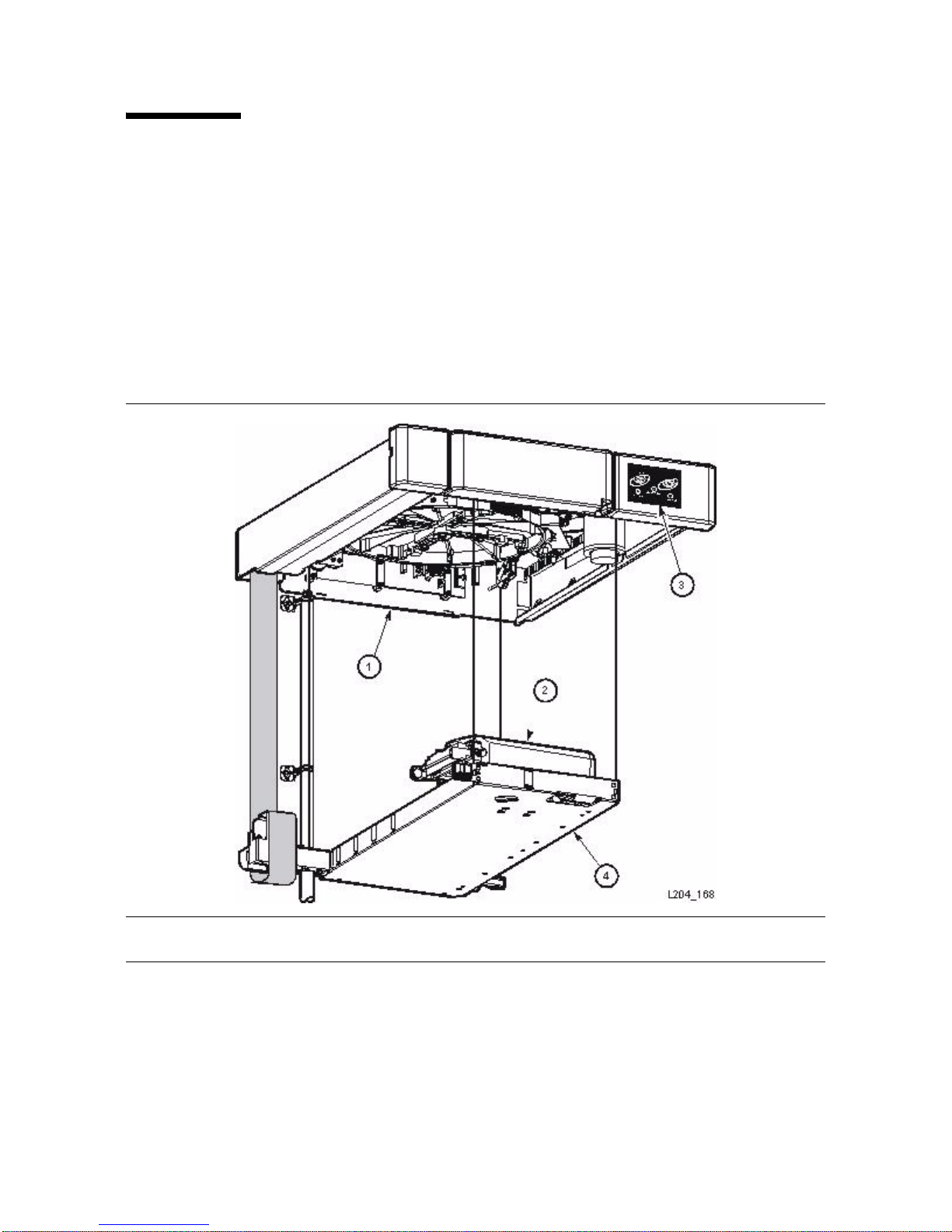
The SL500 library, shown in FIGURE 1-1 and FIGURE 1-2, is a self-contained, fully
automated, cartridge tape storage system that
483 mm (19 in.) rack or cabinet. The base module is also available as a desktop version.
FIGURE 1-1 Front View of Library Components
is scalable and mounts into a standard
1. Base module 5. Library door lock
2. Expansion module 6. Base unit cartridge access port (CAP)
3. Library door 7. Keypad
4. Expansion module cartridge access port 8. Robotics unit (with removable facade)
2 SL500: Systems Assurance Guide • October 2010 Revision MD • MT9212

FIGURE 1-2 Rear View of Library Components
Library Overview
1. Base module 7. RLC controller card
2. Drive expansion module 8. MPU2 (Fibre Channel) or MPW/RLW (SCSI)
3. Cartridge expansion module 9. Library main power switch
4. Redundant power supply 10.Library fans
5. Standard power supply 11.Tape drive 1 in base unit
6. Power supply cord receptacle 12.Tape drive 1 in expansion module
MT9212 • Revision MD Chapter 1 Introduction 3
PUA (Dual Port Fibre Channel-check on availability)

Capacity on Demand
Capacity on Demand
The SL500 library includes the Capacity on Demand feature. Capacity on Demand
separates physical capacity from activated capacity, and allows you to pay only for the
capacity you need. Then as your needs grow, you can add modules and activate the
portion that you need. To expand capacity within a module, you need only purchase
and install an activation key file for the new capacity, and then reboot the library.
Note – Starting with SL500 firmware version 1300 and SLConsole version FRS_4.00,
storage capacity upgrades must be installed through the SL500 activation utility.
This feature controls cartridge storage cells only. All installed tape drives are available
by default. All cells in CAPs configured for enter and eject operations are available if
the module containing the CAP has any activated storage cells.
Capacity on Demand Features and Restrictions
Important features and restrictions of Capacity on Demand that will help your
customer to plan for and use the feature in your SL500 library are:
■ Only activated storage cells can be used for tape cartridge storage. Inactivated cells
cannot be used for cartridge storage, nor can they be accessed by any hosts.
■ The minimum capacity is 30 storage cells for LTO-only libraries, and 24 storage cells
for mixed-media libraries. This is identified as Limited Base hardware activation.
■ Customers can purchase additional capacity in the following increments:
■ FullBase – All storage cells in the Base Module.
■ FullCEM – All storage cells in a cartridge expansion module (CEM).
■ FullDEM – All storage cells in a drive expansion module (DEM).
■ ThirdDEM – One-third of the storage cells in a DEM. For two-thirds of a DEM,
you would install two ThirdDEM. For all of a DEM, you could install three
ThirdDEMs or one FullDEM.
■ After installing additional capacity, you must reboot the library. Once verified by the
library controller, the additional storage cells are available for use.
■ Storage capacity is incremental. Total capacity is equal to the sum of the capacities
specified in each activation key file installed on the library.
■ The order that capacity activation keys are installed is not significant (that is, it does
not need to match the order of the modules in the SL500 frame).
■ The SL500 does not support gaps in activated capacity; all storage cells must be
contiguous. This has the following effects on capacity planning:
■ You can begin adding capacity to a module only if the module directly above it is
at full capacity.
■ Deleting a Capacity key for a module in the middle of a library causes the
modules below it to be unavailable. Any partitioning definitions affect will need
to be re-done to account for the deleted slots.
Note – CEMs must be at the bottom of any SL500 configuration.
4 SL500: Systems Assurance Guide • October 2010 Revision MD • MT9212

Hardware Activation Keys
Hardware Activation Keys
The Hardware Activation utility allows the customer (or a service representative) to
install optional features on the library. This utility begins with SL500 firmware version
1300 and Library Console version FRS_4.00.
Directions for customers to install the hardware activation keys are supplied in the
SL500 User’s Guide, part number 96116.
For SL500 hardware upgrade issues, customers should contact Technical Support and
create a service request.
For SILKS issues, the Storage TSC Tape Support Team (Backline/Tier 3) should e-mail
the SILKS_Help_Team@sun.com.
For SILKS IT application issues, users should create a Service Desk ticket:
Report a Problem > Software Applications > SILKS INFRA
■ AMER: http://servicedesk.central
■ APAC: http://servicedesk.singapore
■ EMEA: http://servicedesk.uk
Two examples of major hardware activations include:
■ Partitioning and
■ Capacity on Demand
Activation Key File
A activation key file is delivered to the customer in an e-mail correspondence. Once
received, the customer (or service representative) can perform this task.
The activation key file is installed through a session in the Library Console.
The key file is a digitally signed image (.img) file containing one or more activation
keys for the features customers have purchased. In order to ensure that features are
installed on the correct library, the activation key file includes the serial number of the
target library and can only be installed on that library.
Each key file is assigned a unique sequence number. The sequence number ensures that
only one instance of an activation key file can be installed on a library at a time.
SL500 hardware activation key files are cumulative. When you install a new key file,
the included features are added to the features already installed on the library. These
key files do not expire.
MT9212 • Revision MD Chapter 1 Introduction 5

Library with LTO-only Cartridge Slots
Library with LTO-only Cartridge Slots
Caution – Firmware problems: You can not mix LTO and mixed-media arrays and
magazines within the same library. If you add expansion modules, the new modules
must have the same type arrays as the existing modules.
The base module can be installed in a rack or placed on a desk, table, or similar sturdy
surface. X-option number XSL500-DESKTP-KTZ contains covers, hardware, and other
items to convert the base module into a desk-top version.
For each library:
■ The base module contains the robotics unit and the base unit:
■ The robotics unit has the robotic components and the keypad
■ The base unit has up to 50 cartridge slots (see note), one or two tape drives, and a
5-slot cartridge access port (CAP).
Note – If the reserved slots are configured as storage slots, the numbering starts there.
The CAP slots also can be configured as storage slots.
■ Drive expansion modules and cartridge expansion modules can be added to a
standard rack to accommodate various slot and tape drive configurations. Yo u m us t
have a FullBase capacity base unit, either from the initial order or with the upgrade
conversion bill, before you can order an expansion module.
■ See Chapter 5, “Ordering” for part numbers.
LTO-only Slot Physical Configurations
Note – Your software might conflict with the following information. Refer to your
software publication for unique information.
The following figures and tables show cartridge slot and tape drive locations.
■ FIGURE 1-3 shows a library with only a base module.
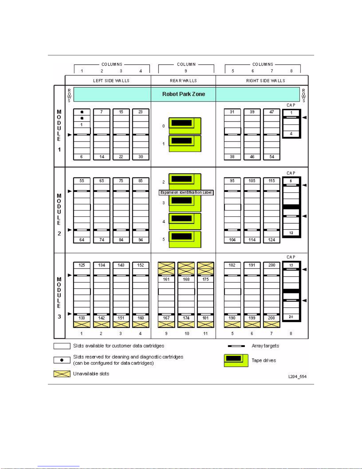
■ FIGURE 1-4 shows a library with a base module that has nine reserved slots, one drive
expansion module, and one cartridge expansion module.
■ FIGURE 1-5 shows a library with a base module that has two reserved slots, one drive
expansion module, and one cartridge expansion module. The storage slot numbering
begins with the first slot after the reserved slots in column 1. The figure shows two
reserved slots, but there could be more. If the reserved slots are configured as
storage slots, the top slot (row 1) would be 1.
■ FIGURE 1-6 shows the slot capacity of a cartridge expansion module according to
which type of module is installed above and below it.
Four integers are used to represent the cartridge and tape drive slots, as viewed from the
front of the library.
6 SL500: Systems Assurance Guide • October 2010 Revision MD • MT9212

LTO-only Slot Physical Configurations
The numbering scheme uses the library, module, row and column scheme.
1. Library number (always 0)
2. Library module number 1 (top of rac
3. Row number 1 through 9 (base module) or 1 through 12 (expansion module)
4. Column number 1 through 9 for base module and drive expansion module, 1
thr
ough 11 for cartridge expansion module
FIGURE 1-3 Base Module, LTO-only Library Slots
k) through 5 (bottom of rack)
MT9212 • Revision MD Chapter 1 Introduction 7

LTO-only Slot Physical Configurations
FIGURE 1-4 Firmware, LTO-only Library Slot Mapping
8 SL500: Systems Assurance Guide • October 2010 Revision MD • MT9212

FIGURE 1-5 SCSI Element Numbering Mapping—LTO-only Library
LTO-only Slot Physical Configurations
MT9212 • Revision MD Chapter 1 Introduction 9

LTO-only Slot Physical Configurations
FIGURE 1-6 LTO-only Library Slots for Back Wall of Cartridge Expansion Module
10 SL500: Systems Assurance Guide • October 2010 Revision MD • MT9212

LTO-only Slot Physical Configurations
LTO-only Capacity Calculations
TABLE 1-1 and TAB LE 1-2 on page 11 relate to LTO-only libraries. The table assumes that,
when DEMs and CEMs are installed in the same
CEMs, as preferred.
Important:
Do not install an EZ DEM below an original CEM. T
Adding LTO slot capacity is covered in Chapter 5, “Ordering”.
TABLE 1-1 LTO-only Capacity Rules
Description Physical Capacity ...with Value
Base Module only (shipped standard) 30 LimitedBase
as last module 50 FullBase
with any module below 66 FullBase
Adding a DEM as
with any module below 84 ThirdDEM (in increments of 28, 28, 28)
Adding a CEM
Module
with any module below 114 FullCEM
CEM after CEM 11 0 FullCEM
with any module below 120 FullCEM
the last module 77 ThirdDEM (in increments of 26, 26, 25)
after a DEM or Base
104 FullCEM
library, the DEMs are above all of the
his is not physically allowed.
TABLE 1-2 LTO-only Capacity Example
Additional
w
Module Capacity Value Installed
ence
Sequ
Number
Ra
Capacity
Available
Additional
Sl
ots*
Library
tal
To
Count
Base Module
Shipped standard LimitedBase 30 30
Full capacity
FullBase 100 +20 50
Drive Expansion Module 16 +16 66
1/3 DEM
(increments of 26, 26, 25)
1/3 DEM
(increments of 26, 26, 25)
1/3 DEM
(increments of 28, 28, 28)
101 77 +26 92
102 +26 118
103 +25 143
Cartridge Expansion Module 7 +7 150
FullCEM 104 104 114 254
MT9212 • Revision MD Chapter 1 Introduction 11

Mixed Media Slot Physical Configurations
Mixed Media Slot Physical Configurations
The following figures illustrate the physical configurations for mixed media libraries.
FIGURE 1-7 Base Module, Mixed-Media Library Slots
12 SL500: Systems Assurance Guide • October 2010 Revision MD • MT9212

FIGURE 1-8 Firmware, Mixed-Media Library Slot Mapping
Mixed Media Slot Physical Configurations
MT9212 • Revision MD Chapter 1 Introduction 13
Mixed Media Slot Physical Configurations
FIGURE 1-9 SCSI Mixed-Media Library Element Numbering Mapping
14 SL500: Systems Assurance Guide • October 2010 Revision MD • MT9212

Mixed Media Slot Physical Configurations
FIGURE 1-10 Mixed-Media Library Slots for Back Wall of Cartridge Expansion Module
MT9212 • Revision MD Chapter 1 Introduction 15

Mixed Media Capacities
Mixed Media Capacities
All capacity counts assume zero reserved slots and all CAPs are configured as I/O
slots. The restricted slot count reduces the available slot capacity one-for-one.
Configuring any CAP slots as storage slots within a module increases the available slots for
1/3 calculations. CAP slots outside any inactivated module—regardless if configured as I/O
or storage—are not available for use.
Caution – Firmware problems: You can not mix LTO and mixed-media arrays and
magazines within the same library. If you add expansion modules, the new modules
must have the same type arrays as the existing modules.
The robotics unit must be PN 314558705 or higher to read SDLT cartridge labels.
Mixed Media Library Capacity Rules
TABLE 1-3 and TABLE 1-4 on page 17 relate to mixed media libraries. The table assumes
that, when DEMs and CEMs are installed in the same
the CEMs, as preferred.
library, the DEMs are above all of
Important:
Do not install an EZ DEM below an original CEM. T
Adding mixed media slot capa
TABLE 1-3 Mixed Media Library Capacity Rules
Description Physical Capacity ...with Value
Base Module only (shipped standard) 24 LimitedBase
as the last module 42 FullBase
with any module below 56 FullBase
Adding a DEM as
with any module below 70 ThirdDEM (in increments of 24, 23, 23)
Adding a CEM
with any module below 94 FullCEM
CEM after CEM 90 FullCEM
with any module below 100 FullCEM
the last module 63 ThirdDEM (in increments of 21, 21, 21)
after a DEM or Base Module 84 FullCEM
city is covered in Chapter 5, “Ordering”.
his is not physically allowed.
16 SL500: Systems Assurance Guide • October 2010 Revision MD • MT9212

Mixed Media Capacities
TABLE 1-4 Mixed Media Library Capacity Example
Additional
w
Ra
Module Value
Sequence
mber
Nu
Capacity
Available
Additional
Slots*
Library
T
otal Count
Base Module Shipped standard 24 24 24
FullBase 100 +18 42
Drive Expansion Module (none) 14 +14 56
1st one under a base
module
ThirdDEM
(increments of 21, 21, 21)
ThirdDEM
(increments of 21, 21, 21)
ThirdDEM
(increments of 21, 21, 21)
101 63
+21 77
102 +21 98
103 +21 119
Drive Expansion Module (none) 7 +7 126
2nd one under another
module
ThirdDEM
(increments of 21, 21, 21)
ThirdDEM
(increments of 21, 21, 21)
ThirdDEM
(increments of 21, 21, 21)
104 63
+21 147
105 +21 168
106 70 189
Drive Expansion Module (none) 7 +7 196
3rd one under another
module
ThirdDEM
(increments of 21, 21, 21)
ThirdDEM
(increments of 21, 21, 21)
ThirdDEM
(increments of 21, 21, 21)
107
63 +21 217
108 +21 238
109 +21 259
Cartridge Expansion Module
(none) 7 +7 +7 256
FullCEM 110 84 +84 350
MT9212 • Revision MD Chapter 1 Introduction 17

Host Notification for Capacity Changes
Host Notification for Capacity Changes
When storage capacity is changed, the library controller notifies all affected hosts
according to their interface requirements. SCSI hosts are notified by a “Mode
Parameters Changed” unit attention. The host must re-audit the library to discover the
configuration changes. Customers must consult the appropriate tape management
software documentation for detailed procedures and commands.
Partitioning Feature—Overview
The SL500 library can now be partitioned into various sections. Briefly stated, this
means that instead of one library (with all its cartridge slots, tape drives and CAPs)
being a single entity, the library and these components can now be divided into
multiple sections (up to eight). Each partition can be accessed by one host or multiple
hosts.
If your customer orders the partitioning feature, the service representative must enable
the feature and work with the systems administrators who will be involved with
assigning the partitions.
Partitioning is an option. Activation is required to enable the feature. See “Hardware
Activation Keys” on page 5 and “Partitioning” on page 73.
Clear communication and cooperation among system programmers, network
administrators and service representatives are essential. Be sure to share this
information with all those involved in the partitioning effort and, if need be,
correspond with other members of the service community when assistance is required.
Note – It is best that all questions are answered before attempting to partition a library.
Partitioning—General
Partitioning has terms associated with it that you and your customer must understand
to effectively use the feature. In certain cases, these terms redefine some concepts that
are familiar with users of the traditional, non-partitioned library configuration.
A “partition” is defined as the process of dividing portions of a library into discrete
sections. The partitioning feature offers great flexibility for users. A partition can be as
small as a single storage slot, a single CAP slot, or one tape drive if desired. A library
can also contain multiple partitions. Customers could also set up a single and/or
multiple partitions that are accessible by single or multiple hosts.
The key to understanding partitioning is knowing what partitions exist, their
boundaries, and who has access to the specific partitions that are configured.
18 SL500: Systems Assurance Guide • October 2010 Revision MD • MT9212

Partitioning Feature—Overview
Setting up a partition requires some important considerations:
■ If one partition designates several tape drives solely to its partition, no other
partitions can use these tape drives.
■ Partition users must also anticipate how much storage area is needed for their
resident tape volumes and the amount of free slots required.
■ CAP assignments are also critical. CAP slots can be specifically assigned to certain
partitions or left open for common use. This will be discussed in detail later.
Storage slots and drives that are not assigned a partition within a partitioned library
cannot be accessed. A customer could leave an area of slots unassigned, for example, in
preparation for a planned future partition.
The SCSI element numbering within partitioned libraries is continuous for each
partition, even if slot locations for each partition are non-contiguous. Using
FIGURE 1-11
as an example, if one partition owns the base and cartridge expansion modules, SCSI
element numbering begins at the first available slot in the base module and continues
through the cartridge expansion module slots. For the partition owning the driving
expansion module, the first slot in that module will begin the element numbering for
that partition and continue throughout the module.
MT9212 • Revision MD Chapter 1 Introduction 19

Partitioning Feature—Overview
FIGURE 1-11 Partitioning a Library
20 SL500: Systems Assurance Guide • October 2010 Revision MD • MT9212

Partitioning Feature—Overview
Partitioning—Access Control
Host definitions are assigned to specific partitions. Customers can assign multiple host
definitions to a single partition. However, they cannot assign the same host definitions
to multiple partitions. For example, Partition 1 could be set up for hosts 2, 3, and 4;
Partition 2 could have hosts 1 and 5 for host definitions. They could not, however,
assign host 1 or 5 to both Partitions 1 and 2.
The host definition consists of:
■ Host ID (WWN)
■ Port number
■ Logical unit number (LUN)
Partitioning—Location Numbering
Location numbering is composed of four digits: Library number, Module number, Row
number, and Column number.
In a non-partitioned library configuration, the location number for the library always
begins with the number “0.” For partitioned libraries, however, the library number will
change to the partition number.
If Partition 1 was composed of the entire base module, locating a cartridge in module
1, row 8, column 1 in the base module would translate into the following: 1, 1, 8, 1.
If Partition 2 was composed of the entire drive expansion module, row 10, column 1
would translate into 2, 2, 10, 1.
Partitioning—CAP Behavior
Whereas cartridge slots and drives can be partitioned, CAPs (or CAP slots) can be
configured for:
■ Assignment to a specific partition only (split assigned CAP)
■ Common use for those partitions that do not specifically assign slots (common CAP)
■ A combination of specific slots and common slots (mixed CAP)
Customers could conceivably partition two slots in an 8-slot CAP to a single partition
and the remaining slots to a second partition, for example.
For partitioned libraries, these three configuration options for CAP assignments are
explained below.
Split Assigned CAPs
As cartridge slots and tape drives can be partitioned, CAPs or CAP slots can be
assigned to the sole use of a partition. When specific CAP slots are assigned to a specific
partition, the split assigned CAP option is enabled
Careful planning in regard to anticipated CAP usage is required when using this
option. Only those CAP slots designated as split assigned can be used by the partition
assigning them.
MT9212 • Revision MD Chapter 1 Introduction 21

Partitioning Feature—Overview
Split Assigned CAPs—Example
The library (see FIGURE 1-1 on page 2) is composed of a base, drive and cartridge
expansion modules. All cartridge slots, drives and CAP slots in the base module
comprise Partition 1. All cartridge slots, drives and CAP slots in the drive expansion
and cartridge expansion modules are assigned to Partition 2. Each partition has access
to only the components configured for it.
If Partition 1 requests a CAP import operation, the procedure is:
■ The operator selects Partition 1’s CAP through either the local operator panel or
SLConsole.
■ The CAP button on the base module is pressed.
■ The top CAP door is opened. All remaining CAP doors remain closed.
■ The operator completes the operation.
If Partition 2 requests a CAP import operation, the procedure is:
■ The operator selects Partition 2’s CAP through either the local operator panel or
SLConsole.
■ The CAP button on the base module is pressed.
■ The top CAP door remains closed. All remaining CAP doors open.
■ The operator completes the operation.
Multiple split CAP assignments are available within a library. This is in contrast to
common assigned CAPs (see below).
Note – As the default behavior, if no partition has selected a CAP through the operator
panel or Library Console, the library will behave as if all split configured CAPs have
been assigned to the CAP button. When the button is pressed, all CAP doors that are
designated as split assigned will open to expose all split configured CAP slots,
provided that no common configured CAP slot containing a cartridge is exposed.
Common (Unassigned) CAPs
The common (or unassigned) CAP configuration is present when there are no specified
CAP slots designated (split assigned) to a partition or partitions. Strictly speaking, one
does not “configure” or “assign” a CAP as common—any CAP slots that are not split
assigned are available for mutual use among the remaining, unassigned partitions.
Keep in mind that common CAPs are a single unit, shared among those partitions that
have no split assigned CAPs.
Common (Unassigned) CAPs—Example
Referring to FIGURE 1-11 on page 20, Partition 1 is set up to contain all cartridge slots and
drives in the base module for a single host. The remaining cartridge slots and drives are
a second partition used only by a second host. However, no CAP slots are explicitly
assigned for a partition—both partitions can use all CAP slots.
An example of an import operation sequence for a common CAP would be:
■ The operator selects the CAP through either the local operator panel or SLConsole.
■ An operator presses the CAP button.
22 SL500: Systems Assurance Guide • October 2010 Revision MD • MT9212

Partitioning Feature—Overview
■ All CAP doors open.
■ A cartridge is placed in any CAP slot.
■ The CAP door is closed.
■ The cartridge is placed into a slot within the requesting host’s partition.
In a second instance, assume that Partition 2 requests a CAP export operation of a
cartridge. Since it is a common CAP, the operation would be:
■ The operator selects the CAP through either the local operator panel or SLConsole.
■ The VOLSER of the cartridge to be exported is entered.
■ The cartridge is placed in any CAP slot.
■ All CAP doors open.
■ The operator completes the operation.
For common CAPs, slots may be used by all partitions who do not specifically assign
them. However, only one partition can select a CAP for operation at one time. The
operation must be completed before the CAP is released to someone else through either
the operator panel or SLConsole.
Mixed CAPs
A mixed CAP option is present when both split CAP and common CAP configurations
are present within a library.
Mixed CAPs—Example
Referring again to FIGURE 1-1 on page 2, Partition 1 contains only the cartridge in module
1, column 5, row 1, and drive number 1 and the single CAP slot 1 in the base module.
The remaining storage slots and drives are divided among partitions 2, 3, and 4. The
remaining CAP slots are left unassigned. These unassigned CAP slots are usable by
partitions 2, 3, and 4, but CAP slot 1 in the base module can only be used by Partition 1.
If Partition 1 requests a CAP export operation, the procedure is:
■ The operator selects its CAP through either the local operator panel or SLConsole.
■ The VOLSER of the cartridge to be exported is entered.
■ The cartridge is placed into the top CAP slot of module 1’s CAP.
■ The top CAP door is opened. All remaining CAP doors remain closed.
■ The operator completes the operation.
If Partitions 2 through 4 request an export operation, the procedure is:
■ The operator selects a CAP through either the local operator panel or SLConsole. For
this example, assume that Partition 2 has selected the top CAP for placement of the
cartridge.
■ The VOLSER of the cartridge to be exported is entered.
■ The cartridge is placed into any module 1 CAP slot except the top one.
■ All CAP doors open.
■ The operator closes all CAP doors.
Within mixed assigned CAP environments:
■ For common CAPs, one or more partitions can share those CAP slots not designated
as split assigned.
MT9212 • Revision MD Chapter 1 Introduction 23

Power System
■ For split assigned CAPs, several configurations are possible. For example, the 4-slot
CAP in a base module could be split assigned to Partition 1; the top four slots in the
drive expansion module’s CAP could be split assigned to Partition 2; the bottom four
slots in the drive expansion module’s CAP could be split assigned to Partition 3, and
so forth. To fulfill the mixed definition, however, there must also be common CAP
slots available.
The CAP Button—Its Function in Partitioned Libraries
A significant difference between a non-partitioned library’s CAPs and those of a
partitioned library must be noted. For a non-partitioned library, pressing the CAP
button opens all CAPs that are configured as CAPs. In a partitioned library, each partition
must first have its CAP selected, using the operator panel or Library Console. This will dedicate
the CAP button to the use of those partitions that selected a CAP or CAPs for operation. After
selection, pressing the CAP button will open only the CAP doors assigned to that
partition.
If not selected by any partition, pressing the CAP button will open only those CAP slots
that are split assigned (see the note
An important thing to remember is that if multiple partitions are assigned to the same
CAP slots (that is, common slots)—and that CAP is selected for use by one
partition—the CAP import/export operation must be completed and the new partition
assignment made, before another member of that partition can gain access for CAP
operations.
on page 22).
Power System
The SL500 library comes with two power options: standard and redundant.
■ The standard option has one 110–240 VAC, single phase, 50–60 Hz power supply that
provides DC power to the library.
■ The redundant option provides an additional power supply as an optional feature. To
provide redundancy, each supply should be plugged into a separate branch circuit.
If something within the power supply or power source fails, the second supply
provides power to the entire library until the failed power supply can be replaced or
the power source is re-established.
See TA BL E 1-7, TA BL E 1-8, and TABLE 1-9 for the power specifications.
24 SL500: Systems Assurance Guide • October 2010 Revision MD • MT9212
Robotics Unit
The robotics unit (FIGURE 1-12) moves cartridges among the storage cells, tape drives,
and cartridge access ports (CAPs) and is included with the base module. The three
main components of t
■ Z drive assembly—Uses a pulley system to vertically move the X table up and down
■ X table assembly—Moves the hand horizontally across the library
■ Hand assembly—Contains the wrist motor, gripper assembly, and bar-code scanner:
■ The wrist motor rotates the hand left and right.
■ The gripper assembly has fingers that grasp the sides of the cartridge.
■ The bar-code scanner targets and reads the volume serial numbers
FIGURE 1-12 Robotics Unit
Robotics Unit
he robotic unit are the:
1. Z drive assembly 3. Keypad (included because of its location)
2. Hand assembly 4. X table assembly
MT9212 • Revision MD Chapter 1 Introduction 25

Electronics
Electronics
The electronics for the library consists of two types of cards:
■ RLC (control) card—Contains the processor and controls the various functions of the
library, such as the robotics, sensors, vision system, and the CAP. The RLC card also
stores the library configuration and volume serial numbers of the cartridge tapes and
their locations.
■ Interface card — Provides the type of interface attachment to the library:
■ MPW/RLW card for a SCSI LVD interface
■ MPU2 card for a Fibre Channel interface
(PUA Dual Port Fibre Channel; check on availability)
FIGURE 1-13 RLC Card Connectors
1. Private Ethernet port is for future use.
2. Not used
3. Public Ethernet port is for remote service access, SLConsole, and SNMP.
4. Fault LED indicates that the control card has detected an error.
5. Reserved for future use.
6. Not used
7. CLI port is an RJ-45 serial port for service representatives.
8. Active LED indicates the library controller is active.
26 SL500: Systems Assurance Guide • October 2010 Revision MD • MT9212

FIGURE 1-14 Keypad
Operator Panels
Operator Panels
There are three ways an operator can use to access the library:
■ Keypad (standard)
■ Remote operator panel using the Library Console (standard)
■ Local operator panel, touch screen (optional feature)
Keypad
FIGURE 1-14 shows the keypad, which has two buttons and five LEDs.
■ The two buttons:
■ Door: calls the robot to move to the parked zone
■ CAP: opens the cartridge access port
■ The five LEDs indicate library activity, service and fault status, CAP and front door
status
1. Open Door button 5. Service Required indicator
2. Open Door indicator 6. Library Active indicator
3. Open CAP button 7. Service Robot indicator
4. Open CAP indicator
MT9212 • Revision MD Chapter 1 Introduction 27

Cartridge Access Port
Library Console
The SL500 uses the StorageTek Library Console (SLConsole), a Java1 application that
provides a graphical user interface (GUI) for the library.
This application is accessed from a remote PC (standard feature) that uses a TCP/IP
connection to the library.
The SLConsole can be used to help diagnose problems with the library and its attached
devices (tape drives, CAPs, and robot). It allows you to:
■ Monitor device activity
■ Load firmware
■ Print reports
Local Operator Panel
The local operator panel is an optional feature that can be used to:
■ View library component details (status, properties, and statistics)
■ Locate a cartridge
■ Move a cartridge
■ Empty the hand
■ Clean a tape drive
Cartridge Access Port
The cartridge access ports (CAPs) are located to the right of the front door of the library.
The base module has one standard CAP:
■ The library with LTO-only arrays has one 5-slot CAP.
■ The library with mixed-media arrays has one 4-slot CAP.
Each expansion module has a CAP consisting of two magazines:
■ The library with LTO-only arrays has two 5-slot magazines.
■ The library with mixed-media arrays has two 4-slot magazines.
1. Java is a general purpose programming language with a nu mbe r of fea tur es t hat mak e th e
language well suited for use on the internet and with Web browsers.
28 SL500: Systems Assurance Guide • October 2010 Revision MD • MT9212

Library Interfaces
The SL500 library uses the following interface connections:
■ Ethernet
■ SCSI LVD
■ Fibre Channel
FIGURE 1-15 Library Interfaces
Library Interfaces
1. Ethernet connection 2. SCSI LVD card (MPW/RLW) 3. Fibre Channel card (MPU2/PUA)
Ethernet
The SL500 uses standard TCP/IP over Ethernet for the Library Console and Simple
Network Management Protocol connections.
Note – A private network connection to an Ethernet hub or switch is recommended for
maximum throughput and minimum contention.
MT9212 • Revision MD Chapter 1 Introduction 29

Library Interfaces
Simple Network Management Protocol
Simple network management protocol (SNMP) is an application-layer protocol that
performs network management operations over an Ethernet connection.
SNMP allows systems administrators to query the library for configuration, operation,
and statistical information plus SNMP allows the library to alert systems administrators
of potential problems.
Systems administrators and network managers can use SNMP to monitor and receive
status from the library, such as:
■ Operational state of the library (firmware, serial number, online/offline)
■ Library elements (columns, panels, slots, CAPs)
■ Number of storage slots, media types, and tape drives
The SL500 library supports SNMPv3 and Management Information Base (MIB) II or
higher.
MIB is a viewable document that contains descriptions about the characteristics for a
managed device. These characteristics are the functional elements for that device which
can be monitored using SNMP software.
For SNMP information, refer to the SL500 Simple Network Management Protocol Guide,
part 316946601.
30 SL500: Systems Assurance Guide • October 2010 Revision MD • MT9212

Library Interfaces
SCSI LVD
The small computer system interface (SCSI) is an ANSI standard, intelligent peripheral
interface that has been in existence since the late 1970’s.
The low voltage differential (
this interface and provides a low noise, low power, low amplitude signal. This lower
signal allows for faster switching and higher data transmission speeds. However, this
lower signal also reduces the length of cable allowed for an LVD bus. An LVD bus can
be up to 12 m (40 ft) long and can support up to 16 devices.
The SL500 library implements the SCSI-3 standard that uses a 16-bit bus, and supports
data ra
Ultra SCSI (Ultra160). L.
FIGURE 1-16 SCSI LVD Example
tes of up to 80 MB/s. SCSI 3 is also know as Ultra3 SCSI, Fast SCSI (Fast-80), or
LVD) implementation is the most recent development of
MT9212 • Revision MD Chapter 1 Introduction 31

Library Interfaces
Fibre Channel
The SL500 Fibre Channel physical interface provides a native connection scheme that
supports open system environments. Topologies include:
■ Switched Fabric
Note: Th
A switched fabric provides dynamic inter
simultaneous Fibre Channel connections for the network. If the library is connected
to a Fibre Channel switch or fabric-capable host, the library configures itself as a
switched fabric topology and can support up to 16 million ports logged into the
fabric.
■ Arbitrated Loop
Note: While
new or future implementations.
Arbitrated loops provide multiple connections for devices that share a single loop
and allow only point-toarbitrated loop can connect up to 126 ports.
FIGURE 1-17 Fibre Channel Example
is topology is recommended for the library.
connections between nodes and multiple,
the library supports the arbitrated loop topology, switched fabric is preferred for
point connections between an initiator and target. An
32 SL500: Systems Assurance Guide • October 2010 Revision MD • MT9212

Library Management Software
Library Management Software
Library management software components control the library and manage the library
database. They also retain volume location and attribute information, plus they perform
activities such as mounts and dismounts, enters and ejects.
There are several software components depending on the platform, connection type,
and operating system.
Note – The same library management software the customer currently has and is
familiar with today can be upgraded to support the SL500 library.
Automated Cartridge System Library Software
Automated Cartridge System Library Software (ACSLS) is an open systems software
package that manages library contents and controls library hardware to mount and
dismount cartridges on tape drives. This application provides library management
services such as cartridge tracking, pooling, reports, and library control.
Note: ACSLS 7.1.x or higher is required.
MT9212 • Revision MD Chapter 1 Introduction 33

Library Management Software
FIGURE 1-18 ACSLS Example
Independent Hardware and Software Vendors
For the most current list of independent hardware and software vendors:
1. Go to http://extranet.stortek.com/inte
2. In the Disk and Library window, select S
3. Click the Get Summary button.
4. Review the Summary Report or click on the Detailed Report button for more
in
formation.
34 SL500: Systems Assurance Guide • October 2010 Revision MD • MT9212
rop/interop?cmd=short_matrix
TK:SL500 and any other filters.

Tape Drives and Cartridges
Tape Drives and Cartridges
See Appendix A or the tape drive publications for information about the tape drives.
Safety Features
The SL500 library has a combination of safety features throughout the library, which
include:
■ Key to open and lock front door
■ Robotics retracted and in a parked position
■ Protective modules for the logic cards
■ Cooling fans to prevent an overheating condition
Front Door and Robotics
The robot is retracted into the park zone in the robotics unit when the front door is
open. Plus, you must use a key to open the front door.
To open the front door:
1. Press the Door Open button on the keypad.
■ The software allows the current job to complete.
■ The software parks the robot by retracting it into the robotics unit.
2. When the Door Open indicator light turns on, use the key to open the door.
The front door must be opened with a key to make sure that the data is secure. If the
door is not fully closed, a sensor relays the condition to the software for security and
safety reasons.
Power is removed from the robot to prevent someone’s hand from being injured.
Cards and Power Supply
The RLC card, interface card, and the power supply are housed inside protective
modules to prevent you from coming into contact with hazardous voltages and
sensitive electronics.
Cooling Fans
The library has two cooling fans that provide cooling for the library electronics.
The tape drives and power supplies have their own fans.
MT9212 • Revision MD Chapter 1 Introduction 35

Specifications
Specifications
The following tables list the specifications for the rack, library and tape drives. See
FIGURE 4-1 on page 63 and FIGURE 4-2 on page 64 for library and rack dimensions.
Note – In the following table, HP is a registered trademark of Hewlett-Packard
Company. IBM is a registered trademark of International Business Machines. SDLT is a
trademark of Quantum Corporation.
TABLE 1-5 Library Component Weights
Component Weight
Base module with 1 power supply, 2 tape drives, and robotics unit 44.5 kg (98.0 lb)
Drive expansion module (DEM) with 1 power supply and 4 tape drives 41.3 kg (91.0 lb)
Cartridge expansion module (CEM) 20.1 kg (44.2 lb)
Robotics unit 10.1 kg (22.2 lb)
Power supply 2.3 kg (5.1 lb)
HP® LTO Ultrium tape drive and tray assy 3.6 kg (7.9 lb)
IBM® LTO Ultrium tape drive and tray assy 4.5 kg (9.9 lb)
SDLT™ LVD tape drive and tray assy 4.2 kg (9.3 lb)
SDLT FC tape drive and tray assy 4.1 kg (9.0 lb)
DLT-S4 tape drive and tray assembly 3.92 kg (8.65 lb)
Tape drive tray assy without tape drive 1.5 kg (3.4 lb)
LTO Ultrium cartridge 221 g (7.8 oz)
TABLE 1-6 Environmental Specifications
Item
Te mp er at ur e
Humidity 20 to 80% 10 to 95% 10 to 95%
Wet bulb (maximum, noncondens
Altitude -76 to 3,048 m (-250 to 10,000 ft)
ing)
Measurements
Operating Storage Transporting
10 to 40ºC
(50 to 104ºF)
+29.2ºC
(+84.5ºF)
10 to 40ºC
(50 to 104ºF)
+35ºC
(+95ºF)
-40 to +60ºC
(-40 to +140ºF)
+35ºC
(+95ºF)
36 SL500: Systems Assurance Guide • October 2010 Revision MD • MT9212

TABLE 1-7 Library Power without Tap e Driv e s
Item Specification
Input voltage 100–240 VAC, single phase
Frequency 50/60 Hz
Maximum library power consumption 1.4 A @ 120 V or 0.8 A
@ 240 V
Maximum heat output 614 Btu/hr
Voltage-amperes 180 VA
TABLE 1-8 Library Power with Tw o LTO Tap e Dri v e s
Item Specification
Input power 219 Watts
Input voltage-amperes 226 voltage-amperes
Input current (100 VAC) 2.3 amperes
Input current (120 VAC) 1.9 amperes
Input current (240 VAC) 0.9 amperes
Btu/hour 748 Btu/hr
Specifications
TABLE 1-9 Library Power with Four LTO Tape Drives
Item Specification
Input power 288 Watts
Input voltage-amperes 297 voltage-amperes
Input current (100 VAC) 3.0 amperes
Input current (120 VAC) 2.5 amperes
Input current (240 VAC) 1.2 amperes
Btu/hour 983 Btu/hr
MT9212 • Revision MD Chapter 1 Introduction 37

Warranties
Warranties
The initial warranty period for the SL500 is:
■ 5-by-9 next business day service level
■ Monday through Friday 8:00 a.m. to 5:00 p.m. Mountain time
■ 12 months from installation
Regulatory Agencies
The following regulatory agencies have tested and certified the SL500 library.
■ Certified by Underwriters Laboratories Inc. (UL) to Standard for Information
Technology Equipment -- Safety -- Part 1: General Requirements
■ UL 60950-1 First Edition
■ CAN/CSA-C22.2 No. 60950-1-03 First Edition
■ EN 60950-1 (IEC 60950-1:2001, modified)
■ CB Scheme in compliance to international Certified Body Scheme requirements with
all national deviations
EN60950-1:2001 Statement
The following statement pertains to products that require a ground connection at the
wall outlet.
Norway:
Apparatet må tilkoples jordet stikkontakt
Finland:
Laite on liitettävä suojamaadoituskoske
Sweden:
Apparaten skall anslutas till jordat uttag
Denmark:
For tilslutning af de øvrige ledere, se m
ttimilla varustettuun pistorasiaan
edfølgende installationsvejledning.
38 SL500: Systems Assurance Guide • October 2010 Revision MD • MT9212

Regulatory Agencies
Electromagnetic
Configuration used for verification and compliance in an SL500 Modular Library with a
TCP/IP connection and 2 to 18 tape drives:
■ Federal Communications Commission (FCC) in compliance to the requirements of
FCC 47, Part15, Subpart B and Unintentional Radiators Class A
■ Voluntary Control Council for Interference (VCCI) (Japan) in compliance to VCCI
Class A (Cispr22)
■ Australia/New Zealand (C-Tick Mark) in compliance to requirements of the
Australia/New Zealand EMC Framework AS/NZS 3548: 1995 Class A
■ European Community (CE Mark) in compliance to the requirements of
Electromagnetic Compatibility Directive 89/336 (including all amendments).
■ Canadian Emissions (ICES) in compliance to the requirements of Canada's
Interference Causing Equipment Standard ICES-003 Class A.
■ Taiwan (BSMI) in compliance to the requirements of Canada's Interference Causing
Equipment Standard ICES-003 Class A.
■ Korea in compliance to the requirements of Korean EMC Law.
Fiber-optic
Each fiber-optic interface in this equipment contains a laser transceiver that is a Class 1
Laser Product.
Each laser transceiver has an output of less than 70 µW.
These Class 1 Laser Products comply with EN60825-1:1994+A1+A2 and with sections 21
R 1040.10 and 1040.11 of the Food and Drug Administration (FDA) regulations.
CF
Warning – Possible Physical Injury. Use of controls or adjustment or
performance of procedures other than those specified herein might result in
hazardous radiation exposure.
Fiber-optic Laser Product Label
In accordance with safety regulations, a label on each StorageTek Fibre Channel
product identifies the laser class of the product and the place and date of the
manufacturer. The label appears on top of a Fibre Channel tape drive and near the Fibre
Channel connectors on a Fibre Channel tape library.
A copy of the label is shown here: The following laser safety and
classification translations are for
users in Finland and Sweden:
CLASS 1 LASER PRODUCT
LASER KLASSE 1
APPAREIL A LASER DE CLASSE 1
COMPLIES WITH 21 CFR 1040.10 AND 1040.11
CLASS 1 LASER
LUOKAN 1 LASERLAITE
KLASSE 1 LASER APPARAT
MT9212 • Revision MD Chapter 1 Introduction 39

Regulatory Agencies
40 SL500: Systems Assurance Guide • October 2010 Revision MD • MT9212

CHAPTER
2
System Assurance
The system assurance process is the exchange of information among team members to
make sure that no aspects of the sale, order, installation and implementation for the
SL500 Library are overlooked. This process promotes an error-free installation and
contributes to the overall customer satisfaction.
The system assurance team members make sure that all aspects of the process are
pl
anned carefully and performed efficiently.
This process begins when the customer accepts the
sales proposal. At this time, a
StorageTek representative schedules one or more system assurance planning meetings.
System Assurance Planning Meetings
The purpose of the system assurance planning meetings are to:
■ Introduce the customer to the StorageTek SL500 Library
■ Explain the system assurance process and establish the team
■ Identify and define the customer requirements
■ Identify the configurations
■ Complete the order
■ Prepare for the installation and implementation
TABLE 2-1 System Assurance Task Checklist
Task Completed?
Introduce the team to the customer. Yes ❑ No ❑
Complete the Team Member Contact sheets in this chapter. Yes ❑ No ❑
Review and complete Ch
Review and complete Ch
Complete the ordering pages in Chapt
Determine the installati
apter 3, “Site Survey” (also in the site kit TM0001) Ye s ❑ No ❑
apter 4, “Site Preparation” (also in the site kit TM0001) Ye s ❑ No ❑
er 5, “Ordering” Yes ❑ No ❑
on schedule: Yes ❑ No ❑
MT9212 • Revision MD 41

Customer Team Member Contact Sheet
Customer Team Member Contact Sheet
Complete the following with information about the customer team members:
Name:
Title:
Telep h o n e Numb e r :
FAX N umber:
Cell Phone / Pager:
E-mail Address:
Name:
Title:
Telep h o n e Numb e r :
FAX N umber:
Cell Phone / Pager:
E-mail Address:
Name:
Title:
Telep h o n e Numb e r :
FAX N umber:
Cell Phone / Pager:
E-mail Address:
Name:
Title:
Telep h o n e Numb e r :
FAX N umber:
Cell Phone / Pager:
E-mail Address:
42 SL500: Systems Assurance Guide • October 2010 Revision MD • MT9212

StorageTek Team Member Contact Sheet
Complete the following with information about the StorageTek team members:
Name:
Title:
Telep h o n e Numb e r :
FAX N umber:
Cell Phone / Pager:
E-mail Address:
Name:
Title:
Telep h o n e Numb e r :
FAX N umber:
Cell Phone / Pager:
E-mail Address:
StorageTek Team Member Contact Sheet
Name:
Title:
Telep h o n e Numb e r :
FAX N umber:
Cell Phone / Pager:
E-mail Address:
Name:
Title:
Telep h o n e Numb e r :
FAX N umber:
Cell Phone / Pager:
E-mail Address:
MT9212 • Revision MD Chapter 2 System Assurance 43

StorageTek Team Member Contact Sheet
44 SL500: Systems Assurance Guide • October 2010 Revision MD • MT9212

CHAPTER
3
Site Survey
This chapter provides space where you can record the different platforms, applications,
and hardware configurations your customer currently has.
The type of information you need to gather includes:
■ “System Configuration” on page 46
■ “Applications” on page 48
■ “Databases” on page 50
■ “Hardware Configurations” on page 51
■ “Library” on page 51
■ “Tape Drives” on page 52
■ “Cartridge Tapes” on page 53
■ “Network” on page 54
■ “Cables and Connectors” on page 56
MT9212 • Revision MD 45

System Configuration
System Configuration
Use these two pages to record information about the customer’s operating systems and
configurations.
TABLE 3-1 Questions About the Customer’s Operating Systems
Question Answer
1. How many and what types of operating systems or
platforms does the customer have?
Open-Systems:
■ Windows: 2000, NT
Make and model:
Quantity:
■ UNIX: Solaris, AIX, HP-UX
Make and model:
Quantity:
■ Linux
Make and model:
Quantity:
Main-Frame:
■ MVS
Make and model:
Quantity:
■ VM
Make and model:
Quantity:
Other (Specify):
■ Make and model:
Quantity:
2. Are there plans for:
■ New purchases?
■ Future upgrades?
■ If so, what?
3. How many systems/servers are used as:
■ Backup servers?
■ File servers?
■ Print servers?
■ Exchange servers?
46 SL500: Systems Assurance Guide • October 2010 Revision MD • MT9212

System Configuration
TABLE 3-2 Current System Configuration
System ___________________ Processor _ ______________ Processor _______________
Vendor make and model
Operating system type
Version number and patch level
Number of channels
IP address
HBA vendor and model
HBA firmware versions
Switch make and model
Switch and port numbers
System ___________________ Processor _ ______________ Processor _______________
Vendor make and model
Operating system
Version number and patch level
Number of channels
IP address
HBA vendor and model
HBA firmware versions
Switch make and model
Switch and port numbers
System ___________________ Processor _ ______________ Processor _______________
Vendor make and model
Operating system
Version number and patch level
Number of channels
IP address
HBA vendor and model
HBA firmware versions
Switch make and model
Switch and port numbers
MT9212 • Revision MD Chapter 3 Site Survey 47

Applications
Applications
Use these two pages to record information about the customer’s applications.
TABLE 3-3 Questions About the Customer’s Applications
Question Answer
1. How are backups performed, manually or automatically?
2. How many servers or systems perform backups?
3. On what days are backups performed?
4. What types of backups are performed and when?
■ Full
■ Incremental
■ Differential
5. How many hours are available for:
■ Full backups
■ Daily Backups
6. How much data is backed up:
■ Per day
■ Per week
■ Per month
7. What percentage of data changes daily?
8. Are backup windows being met?
9. How long does it actually take?
10.How long should a backup take?
11.Is a different backup schedule needed?
12.How long does the customer kee
backed up data?
13.How many copies are made, including the original?
14.How many copies are archived?
15.How often are restores necessary?
16.Why are restores necessary?
17.What are the restore requirements?
18.What are the restore objectives?
p the different levels of
48 SL500: Systems Assurance Guide • October 2010 Revision MD • MT9212

TABLE 3-4 Current Backup and Archive Software
Selection Type of Backup and Archive Software Version
❑ Veritas NetBackup
❑ IBM Tivoli Storage Manager (TSM)
❑ Legato NetWorker
❑ CA Brightstor
❑ HP Omniback
❑ Commvault Galaxy
❑ E-Mail Archive
❑ ASM NT
❑ ASM UNIX
❑ Other (Specify)
❑ Other (Specify)
Applications
TABLE 3-5 Current Network Management Software
Selection Type of Management Software Version
❑ Ver i ta s
❑ IBM Tivoli NetView
❑ HP OpenView
❑ HP SUNNet
❑ Horizon Library Monitor
❑ RMS/GSM
❑ Other (Specify)
❑ Other (Specify)
TABLE 3-6 Current Library Attachment Software
Selection Type of Attachment Software Version
❑ ACSLS
❑ ACSLS HA
❑ Direct SCSI
❑ Fibre Channel
❑ Other (Specify)
MT9212 • Revision MD Chapter 3 Site Survey 49

Databases
Databases
Use this page to record information about the customer’s databases.
TABLE 3-7 Questions About the Customer’s Database
Question Answer
1. How much primary storage exists?
Total capacity.
2. What type and size of disk
have?
Make:
Model:
Capacity:
Quantity:
Make:
Model:
Capacity:
Quantity:
3. What is the RAID configuration?
4. What type of failover product and version is the
cus
tomer using?
5. Does all primary storage require backup?
If not, how much does?
6. Are additional storage devices needed?
7. What database management system does the customer
have?
8. What types of databases need backups?
9. What is the size of the smallest database?
10.What is the size of the largest database?
11.How often does the customer back up each database?
12.What type of data is the customer backing up?
13.How valuable is the data in each database?
14.Do the different databases have different backup
equirements?
r
15.How is the customer cur
databases (tape backup, mirroring, snapshot)?
16.If mirroring, how many mirrors?
17.Is mirroring installed because failover is required?
drives does the customer
rently protecting the
50 SL500: Systems Assurance Guide • October 2010 Revision MD • MT9212

Hardware Configurations
Use the remainder of this chapter to record any existing hardware.
■ Does the customer have any existing libraries? ❑ Ye s ❑ No
■ Does the customer have any existing tape drives? ❑ Ye s ❑ No
■ Does the customer have any existing media for reuse? ❑ Ye s ❑ No
■ Does the customer have an existing storage area network? ❑ Yes ❑ No
■ Are migration services required? ❑ Yes ❑ No
Library
■ Will this library be replacing existing libraries? ❑ Yes ❑ No
■ Will this library be replacing existing StorageTek libraries? ❑ Ye s ❑o No
■ If so, what are the module numbers? _______________
TABLE 3-8 Existing Libraries
Hardware Configurations
Libraries Description Quantity
Manufacturer
Make and model
Cartridge capacity
Manufacturer
Make and model
Cartridge capacity
Manufacturer
Make and model
Cartridge capacity
MT9212 • Revision MD Chapter 3 Site Survey 51

Hardware Configurations
Tape Drives
The SL500 supports LTO, SDLT, and DLT-S4 tape drives as described in Appendix A.
If the customer has other types of tape drives,
■ Does the customer have existing StorageTek tape drives? ❑ Ye s ❑ No
■ Does the customer need more tape drives? ❑ Yes ❑ No
■ What types of drives are needed? ___________________
TABLE 3-9 Existing Tape Drive Types
Tape Drive Type Yes No Vendor
3480 or 3490-type devices (18/36 track) ❑ ❑
DLT 7000 or 8000 ❑ ❑
StorageTek T9840 or T9940 ❑ ❑
StorageTek T10000 ❑ ❑
SDLT 320 or 600 ❑ ❑
DLT-S4 ❑ ❑
LTO Generation 1, 2, 3, 4, or 5 ❑ ❑
media migration services are required.
TABLE 3-10 New Tape Drives
Tape D riv es Description Quantity
Manufacturer
Make and model
Comments:
Manufacturer
Make and model
Comments:
Manufacturer
Make and model
Comments:
Manufacturer
Make and model
Comments:
Does the customer need to migrate from on
Does the customer need help relocating cartridge
e tape drive technology to another? ❑ Yes ❑ No
tapes, tape drives, and racks? ❑ Yes ❑ No
See “Data Center Services” on page 58 for more information.
52 SL500: Systems Assurance Guide • October 2010 Revision MD • MT9212

Hardware Configurations
Cartridge Tapes
■ Approximately, how many cartridge tapes does the customer have? _____
■ Does the customer need more tapes? ❑ Yes ❑ No
■ Data cartridges? ❑ Yes ❑ No
■ Cleaning cartridges? ❑ Yes ❑ No
■ Are all cartridge tapes labeled with “approved” labels? ❑ Ye s ❑ No
TABLE 3-11 Existing Cartridge Tapes
Cartridge Tapes Descripti o n Quantity
Data cartridge type
Manufacturer
Data cartridge type
Manufacturer
Data cartridge type
Manufacturer
Data cartridge type
Comments:
Cleaning cartridge type
Manufacturer
Cleaning cartridge type
Manufacturer
Cleaning cartridge type
Manufacturer
Cleaning cartridge type
Comments:
Does the customer need to migrate
old data or technology to LTO? ❑ Yes ❑ No
Does the customer need help relocating c
See “Data Center Services” on page 58 for more information.
artridge tapes to the new library? ❑ Ye s ❑ No
MT9212 • Revision MD Chapter 3 Site Survey 53

Hardware Configurations
Network
■ Does the customer have an existing storage area network? ❑ Yes ❑ No
■ Are additional network devices required? ❑ Yes ❑ No
■ What are they? ____________________
■ Does the customer use zones in the network? ❑ Yes ❑ No
■ Are there frequent reconfigurations of the network? ❑ Yes ❑ No
■ Are there multiple floors involved with this network? ❑ Yes ❑ No
■ Are there inter-connections of hubs and switches? ❑ Yes ❑ No
■ Are there remote connections to hubs and switches? ❑ Yes ❑ No
■ Is this a campus network? ❑ Ye s ❑ No
■ Are trunk cables used? ❑ Yes ❑ No
■ Are patch panels used? ❑ Ye s ❑ No
TABLE 3-12 Fibre Channel Switches
Information Switch 1 Switch 2 Switch 3
Manufacturer
Make and model
Software version
Speed
Number of ports
Port types
GBIC module types
Number of open ports
IP addresses
IP addresses
TABLE 3-13 Ethernet Hubs and Switches
Information Hub/Switch 1 Hub/Switch 2 Hub/Switch 3
Manufacturer
Make and model
Number of ports
Software version
Speed
Duplex
Number of open ports
IP addresses
IP addresses
54 SL500: Systems Assurance Guide • October 2010 Revision MD • MT9212

Hardware Configurations
TABLE 3-14 Fibre Channel Switch Connections
FC Switch Information Switch 1 Switch 2 Switch 3
Ve nd o r
Model number
Port 0 connection and status
Port 1 connection and status
Port 2 connection and status
Port 3 connection and status
Port 4 connection and status
Port 5 connection and status
Port 6 connection and status
Port 7 connection and status
Port 8 connection and status
Port 9 connection and status
Port 10 connection and status
Port 11 connection and status
Port 12 connection and status
Port 13 connection and status
Port 14 connection and status
Port 15 connection and status
Port 16 connection and status
Port 17 connection and status
Port 18 connection and status
Port 19 connection and status
Port 20 connection and status
Port 21 connection and status
Port 22 connection and status
Port 23 connection and status
Port 24 connection and status
Port 25 connection and status
Port 26 connection and status
Port 27 connection and status
Port 28 connection and status
Port 29 connection and status
Port 30 connection and status
Port 31 connection and status
MT9212 • Revision MD Chapter 3 Site Survey 55

Hardware Configurations
Cables and Connectors
Note – Plan for 1 to 2 m (3 to 7 ft) of slack cable for limited movement and routing.
TABLE 3-15 Cables and Connectors
Type Connector Length Quantity
Fibre Channel
9 micron fiber-optic LC-to-LC
LC-to-SC
Other (specify)
50 micron fiber-optic LC-to-LC
LC-to-SC
LC-to-ST
Other (specify)
Fibre Channel copper DB-9
HSSDC
Ethernet (CAT5E) RS-232
Other (specify)
SCSI (l
ist the connector, length, and quantity)
Note – The SL500 library and tape drives use only SCSI LVD high density connectors
and Fibre Channel LC connectors. If the customer uses other types of cables and
connectors, a new cable plan should be created.
FIGURE 3-1 shows several types of connectors for identification purposes only.
56 SL500: Systems Assurance Guide • October 2010 Revision MD • MT9212

FIGURE 3-1 Connector Types - Identification Chart
Hardware Configurations
MT9212 • Revision MD Chapter 3 Site Survey 57

Data Center Services
Data Center Services
Whether your customers needs a new data center, a relocation, or an audit, Data Center
Services (DCS) has the resources to analyze, plan and manage a project of any size.
In the information-gathering phase, DCS:
■ Gathers information about your customer's environment and requirements from
audits, network maps, equipment inventories, and staff interviews.
■ Determines the scope of work and resources required.
■ Validates the requirements and formally state their findings in reports, executive
summaries, and project plans.
■ Manages the project through completion once the scope, methods, and deliverables
are agreed upon.
Data Center Services are available for customers, for both short- and long-term projects.
Offerings:
■ Hardware relocation and asset swaps
■ Asset management.
Identify assets of a data center and place them into a controllable state
■ Custom cabling, connectivity, conveyance, and design
Provide cabling infrastructure to optimize performance, maintenance, and migration
to emerging technologies.
■ Media services.
Relocate tapes and racks, and/or convert one form of media to another.
■ Infrastructure services.
Design, remodel and optimize existing facilities.
■ Data center project management.
For more information, contact your local Professional Services and Data Center Services
representative.
58 SL500: Systems Assurance Guide • October 2010 Revision MD • MT9212

CHAPTER
4
Site Preparation
This chapter contains a site planning checklist to help prepare for an SL500 Library
installation.
Site Planning Checklist
Make sure that the entire route of your staging will accommodate the width of the
pallets, and, if applicable, the overall height of the rack and pallet jack.
TABLE 4-1 Site Planning Checklist
Question Completed Comments:
Delivery and Handling Factors
Does the customer have a delivery dock?
If no, where will the equipment be delivered?
If a delivery dock is available, what are the hours of
operation?
Are there street or alley limitations that may hinder
delivery?
Will people be available to handle the delivery of
the library?
Will equipment be available to handle the library
(forklifts and/or pallet jacks)?
Are the ramp angles less than 10 degrees? Yes ❑ No ❑
Is the dock close to the computer room where the
library will be installed?
Is an elevator available to move the library to the
appropriate floor?
Is there a staging area where the library can be
placed with access to the installation site?
Yes ❑ No ❑
_____________
Yes ❑ No ❑
Yes ❑ No ❑
Yes ❑ No ❑
Yes ❑ No ❑
Yes ❑ No ❑
Yes ❑ No ❑
MT9212 • Revision MD 59

Site Planning Checklist
TABLE 4-1 Site Planning Checklist (Continued)
Question Completed Comments:
Physical Placement Factors
Does the site have raised flooring? Ye s ❑ No ❑
Has the floor been laser-leveled or within 1 to 2
Yes ❑ No ❑
degrees level?
If a rack was ordered, are there door height
limitations to be aware of?
If a customer’s rack is being used, is its depth more
than 80 cm (31.5 in.) but less than 94 cm (37 in.)?
Can the customer’s floor support the weight of the
Yes ❑ No ❑ The rack on a pallet with a pallet jack is
210 cm (6.9 ft) high.
Yes ❑ No ❑ Contact Technical Support for optional
rear extensions, kit number 419930101.
Yes ❑ No ❑
library?
Does the customer have floor tile cutouts available
for AC power, interface cables, and vented floor
tiles for cooling?
Does the intended site have enough room to install
Yes ❑ No ❑ Cutouts are placed at the rear of the
library/rack. Vented tiles should be
placed in front of the library.
Yes ❑ No ❑ Front and rear access: 61 cm (2 ft)
and service the equipment?
Are there plans for expansion?
Yes ❑ No ❑
If so, when?
Does the customer want to expand the:
■ Cartridge capacity?
■ Drive capacity?
Environmental Factors
Does the site meet the environmental requirements:
■ Temperature?
■ Humidity?
■ Cooling?
■ Heat generated by the library?
Does the site contain features and materials that
guard against electrostatic discharge (ESD)?
Are there special requirements to dispose of or
recycle the packing material, pallets, and
cardboard?
Is space available for spare parts and
documentation?
Power Factors
Does the intended site meet the power
requirements for of the equipment?
Does the site have multiple, separate circuits for
power redundancy?
Does the customer plan to use multiple branch
circuits for redundancy?
Will new electrical wiring be needed?
If new electrical wiring is necessary, will it require
an inspection or an approval to satisfy local codes?
Date: ______
Yes ❑ No ❑
Yes ❑ No ❑
Yes ❑ No ❑ Temperature: 10º–40ºC (50º–104ºF)
Humidity: 20–80%, non-condensing
Yes ❑ No ❑
Yes ❑ No ❑
Yes ❑ No ❑
Yes ❑ No ❑ 100–240 VAC, single phase, 50–60 Hz
Yes ❑ No ❑
Yes ❑ No ❑
Yes ❑ No ❑
Yes ❑ No ❑
60 SL500: Systems Assurance Guide • October 2010 Revision MD • MT9212
Site Planning Checklist
TABLE 4-1 Site Planning Checklist (Continued)
Question Completed Comments:
Connectivity Factors
Note: Cabling is very important to establish a reliable network for the library and tape drives.
Have you completed a cable plan? Yes ❑ No ❑
Have you determined the type and number of
cables required?
■ Ethernet: host connections
■ Fibre Channel: data path and host
■ SCSI LVD: data path and host
Is the customer prepared to supply Ethernet cables
Yes ❑ No ❑
Yes ❑ No ❑
Yes ❑ No ❑
Yes ❑ No ❑
Yes ❑ No ❑
Each tape drive needs an interface
connection (data path).
Quantity: ________
Quantity: ________
Quantity: ________
for the network?
Can the customer provide the required number of
Yes ❑ No ❑
static IP addresses?
Will interface cables be run from outside the
computer room?
Will the customer allow StorageTek to use remote
Yes ❑ No ❑ Cables that run outside a raised floor
computer room require a flammability
rating of CL2 or CL2P.
Yes ❑ No ❑
support?
Ta p e D r i ves
Does the customer have the correct type and
Yes ❑ No ❑
number of tape drives?
Are additional tape drives required?
How many?
Media Factors
Does the customer have the correct type and
Yes ❑ No ❑
___________
Yes ❑ No ❑
number of cartridge tapes?
■ Are additional cartridges required?
■ Are cleaning cartridges required?
■ Are labels required?
Human Factors
Yes ❑ No ❑
Yes ❑ No ❑
Yes ❑ No ❑
Where will the remote operator panel be located? Ye s ❑ No ❑
Does the customer need additional CAP
Yes ❑ No ❑
magazines?
Any Comments and/or other Concerns:
See Appendix A, “Tape Drives and
Cartridges” for information about the
tape drives.
MT9212 • Revision MD Chapter 4 Site Preparation 61

Preparing for the Installation
Preparing for the Installation
Site preparation is important to make sure that no aspects of the installation and
implementation are overlooked and to promote an error-free installation.
Considerations that you and the customer must make before the equipment arrives are
outlined in the following sections.
Personnel
To install an SL500 library, you need at least two qualified installers to lift some of the
components from the boxes and to lift the base unit into the rack. A lifting tool is
available for the original-design modules to hold the base unit in the rack so that one
person can install the front and back screws.
Installation tips are supplied in the Installatio
n Manual.
Tools
TABLE 4-2 lists the tools used to install the library, both standard tools found in most tool
kits and special tools, with part numbers and quantity.
TABLE 4-2 Installation Tools
Tool Pa rt Nu mb er Quantity
Standard Service Tool Bag
Tools include:
■ T10, T15, T20, and T25 Torx bits and driver,
■ Standard screwdrivers
■ Phillips screwdrivers
■ 1/8 Allen wrench
Additional equipment
■ Step stool
■ Gloves
■ Flashlight
24100250 1
Field Service Grounding Kit (ESD Kit) 4711 1
Optional SL500 install tool kit
(temporarily installed in rack to s
62 SL500: Systems Assurance Guide • October 2010 Revision MD • MT9212
314829201 A/R
upport original design base unit)

Physical Planning
The following figures show the dimensions for the SL500 library.
FIGURE 4-1 Library and Rack Dimensions (Sheet 1 of 2)
Physical Planning
1. 48.3 cm (19.0 in.) width of front of base module with flange
2. 35.6 cm (14.0 in.) height of base module
3. 35.6 cm (14.0 in.) height of expansion module
4. 46.5 cm (18.3 in.) distance between rack holes
5. Original design modules (shown in figure): 60.9 cm (24.0 in.) to 86.4 cm (34.0 in.), optimally 74 cm (29 in.) front to
rear rack mounting distance.
EZ install modules: 5
Note: Extensions (optional accessory kit part 419930101) are available for rack depths up to 94 cm (37.0 in.).
6. 44.5 cm (17.5 in.) width of back of base module
MT9212 • Revision MD Chapter 4 Site Preparation 63
5.9 cm (22.0 in.) to 78.7 cm (31.0 in.), optimally 66 cm (26 in.) front to rear rack mounting.
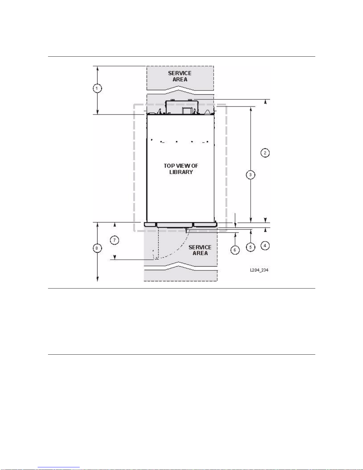
Physical Planning
FIGURE 4-2 Library and Rack Dimensions (Sheet 2 of 2)
1. 60.9 cm (2 ft) minimum service clearance behind the library or rack
2. 81.0 cm (31.9 in.) depth of base module from f
3. 76.2 cm
4. 3.8 cm (1.5 in.) depth of front door, required clearance
5. 5.3 cm (2.1 in.) depth of front
6. 5.9 cm (2.3 in.) key depth
7. 24.1 cm (9.5 in.) front door op
8. 60.9 cm (2 ft) minimum front service clearance
(30.0 in.)depth of original design base module
71.4 cm
(28.1 in.) depth of EZ install base module
64 SL500: Systems Assurance Guide • October 2010 Revision MD • MT9212
ront mounting plane to back of tape drives
door and unique latch hardware
ening clearance

EZ Install Modules
EZ Install Modules
The EZ install modules are easier to install into a rack because the arrays, doors, and
front panels are already installed on the modules. The service representative installs
rails and brackets into the rack and slides in the modules, then attaches them to the
rack.
Caution – Compatibility issues: You can add the EZ install modules into a rack that has
the original design modules, but you cannot add the original design modules into a rack
with all EZ install modules. See the following rules.
Customers who purchased the original design version of the library and who want to
add modules can either:
■ Order original design expansion modules
■ Order EZ install modules
■ Once an EZ install module has been installed, only EZ install modules can be
installed below that module. See the following examples:
■ Base Module (original) DEM (original) DEM (EZ) CEM (original) No
■ Base Module (original) DEM (original) DEM (EZ) CEM (EZ) Ye s
Customers who purchased the EZ install version of the library and who want to add
modules must order only EZ install modules.
As with the original designed modules, the EZ modules are not customer-installable.
AC Power Planning
Keep in mind the following power considerations:
■ Plan the location for a second set of power wiring even if the customer is not
purchasing the redundant power supply.
■ Make sure that each power source is on a separate branch circuit.
■ If the rack has a power distribution unit (PDU), plug each power cable from the
power supply receptacle to the PDU, and then plug the PDU cable to the wall
receptacle.
■ If the rack does not have a PDU, plug each power cable from the power supply
receptacle to the wall receptacle.
MT9212 • Revision MD Chapter 4 Site Preparation 65

Rack Planning
Rack Planning
The SL500 library is a rack-mountable library that requires a standard 483-mm (19-in.)
rack or cabinet for installation.
Most racks contain units of measure which are called RU’s (rack units). Each RU is
equal to 44.5 mm (1.75 in.) and appear as a 3-hole pattern on the frame of the rack. For
i
nstance, some racks have numbers, notches, or markings to show where the top of the
RU begins (see
FIGURE 4-3 Rack Frames and Rack Unit Measuring Identification
FIGURE 4-3 for an example).
1. Where the RU starts 2. The 3-hole RU pattern
The installation manual provides detailed instructions about where to install rack
hardware and the adjustable brackets.
Remote Support
Service Representatives are available to assist you and the customer with hardware and
software problem resolution. During the initial order and installation planning, make
sure that you inform the customer about local and remote support.
Does the customer want remote support? Ye s
❑ No ❑
66 SL500: Systems Assurance Guide • October 2010 Revision MD • MT9212

CHAPTER
5
Ordering
This chapter describes the components and the ordering part numbers for the
Modular Library System.
SL500
■ Some numbers are for ordering the initial library.
■ X-options (upgrades) are kits of material and instructions that allow you to add a
feature or an upgrade to the library after the base module has been installed.
To add a module, the module above must have full capacity. For example:
■ To add a drive expansion or cartridge expansion module below a base module, the
base module must have 50 (LTO-only) or 42 (multi-media) available cartridge slots.
■ Slots must be contiguous. Slots within a lower module will not be recognized unless
the upper module is fully activated.
MT9212 • Revision MD 67

Hardware Activation Files
Hardware Activation Files
Activation files are required to enable certain features purchased for the SL500.
Any parts that contain the phrase “MUST REQUEST HARDWARE ACTIVATION FILE”
in the description require an activation file to be loaded to the SL500 library.
Activation Files for New Libraries
To ensure proper hardware activation file creation and delivery:
1. Only place ONE library on any sales order or quote:
2. Include E-mail Addresses:
The reason for this requirement is that we have to create the hardware activation
files specific to each library. If two libraries are on the same order, we do not know
which features should be applied to which library.
In the footnotes section of your Webdesk quotes you need to place all the e-mail
address (limit of up to three addresses) where you would like the hardware
activation file sent.
a. Proceed each e-mail address with: “HARDWARE ACTIVATION FILE”
The hardware activation file is customer-installable.
Upgrades to Existing Libraries
To ensure proper hardware activation file creation and delivery:
1. Only place ONE library's upgrade on any sales order / quote:
The reason for this requirement is that we have to create the hardware activation
files specific to each library. If two libraries are on the same order, we do not know
which features should be applied to which library.
2. Include E-mail Addresses:
In the footnotes section of your Webdesk quotes you need to place all the e-mail
address (limit of three addresses) where you would like the hardware activation file
sent.
a. Proceed each e-mail address with: “HARDWARE ACTIVATION FILE”
The hardware activation file is customer-installable
3. Include Library Serial Number:
The library serial number must be included in the footnotes area of the Webdesk
quote along with the e-mail addresses.
68 SL500: Systems Assurance Guide • October 2010 Revision MD • MT9212

Library with Base Module—LTO Only
Library with Base Module—LTO Only
The following table lists the part numbers for the library with a base module and LTO
tape drives and arrays only.
You must request an Activation File, RoHS-5, for all products.
TABLE 5-1 Base Module—LTO-only
Description Par t N um be r
SCSI Interface
SL500 base module, 30 slots, SCSI interface SL500-30-SCSI-Z-N ❑
SL500 bundle, base module, 30 slots, SCSI, two HP LTO4 SCSI drives SL500-30L4HPSC-Z ❑
SL500 bundle, base module, 30 slots, SCSI, two IBM LTO4 4Gb SCSI drive SL500-30L4IBSCZ-N ❑
Fibre Channel (FC) Interface
SL500 base module, 30 slots, Fibre Channel (FC) interface SL500-30-FC-Z-N ❑
SL500 bundle, base module, 30 slots, FC, two HP LTO3 4Gb FC drives SL500-2L34-30FC-Z ❑
SL500 bundle base module with 30 slots, FC, two HP LTO4 4Gb FC drives SL500-30L4HP4GFZ-N ❑
SL500 bundle base module with 30 slo
SL500 bundle base module, 30 slots, FC,
ts, FC, two HP LTO4 4Gb FC drives SL500-30L4HPSC-Z-N ❑
two IBM LTO4 4Gb FC drives SL500-30L4IB4GFZ-N ❑
MT9212 • Revision MD Chapter 5 Ordering 69

Upgrade (X-options)—All Libraries
Upgrade (X-options)—All Libraries
The table below lists the upgrade or X-options available.
Note: Y
TABLE 5-2 Library and Module Upgrades (X-options)—All Libraries
Short Description Long Description X-option Number
SL500 30-50 slots
SL500 DEM w/ 1/3 slots LTO-on ly: DEM w
SL500 1/3 DEM slots
SL500 LTO CEM
Mixed Media 24-42 slots
Mixed Media DEM 1/3 Mixed Media: DEM
Mixed Media DEM
Additional 1/3 slots
Mixed Media CEM Mixed Media: cartridge expansion module
SL500 Partitioning
SL500 Partitioning
for Legato
ou must request an Activation File, RoHS-5, for all products.
LTO -onl y: t
active slots (the CAP is not counted in slot
capacity and is an additional 5 slots).
activated
LTO -onl y: upgrade for access to second 1/3
and/or third 1/3 DEM slots
LTO -onl y: cartridge expansion module
(these modules do not contain drive bays).
Mixed Media: takes base module from 24 to
42 active slots (the CAP is not counted in
slot capacity and is an additional 4 slots).
access
Mixed Media: DEM upgrade for access to
second 1/3 and/or third 1/3 DEM slots
(these modules do not contain drive bays).
Physical partitioning feature, up to 8
partitions allowed.
Maintains the Legato boundary after
installing any ne
akes base module from 30 to 50
ith first 1/3 slots
1.
1.
with first 1/3 slots
2.
w library hardware.
XSL500KBASE30-50-N ❑
XSL500K-DEM-W1/3-N ❑
X-SL500K1/3SLOTUP-N
XSL500K-LCARTEX-N ❑
XSL500K-MM-24-42-N ❑
XSL500K-MM-DREXP-N ❑
XSL500K-MM-1/3DEM-N ❑
2.
XSL500K-MM-CEM-Z-N ❑
X-SL500K-PARTNG-N ❑
XSL500K-LEG-PARTG-N ❑
❑
Notes:
1. Up to three 1/3 files can be ordered. If this is the
the third adds 25 slots. If there is a module below, increments are 28, 28, and 28.
2. Up to three 1/3 files can be ordered. If this is the last module, slot
file. If there is a module below, increments are 24, 23, 23.
70 SL500: Systems Assurance Guide • October 2010 Revision MD • MT9212
last module, the first two 1/3 files add 26 slots each and
counts increment by 21 for each 1/3

Power Cord Numbers and Receptacles
Power Cord Numbers and Receptacles
■ The following tables list power cord part numbers by country.
■ All cords are 3 m (9.81 ft). The receptacle type is listed also.
■ Refer to the vendor catalog for the part number.
If your country is not listed below, use the
TABLE 5-3 Country-specific Power Cords
cord that you used on past products.
Input Voltage Country Par t Nu mb er Receptacle Type
100 to 127 VAC U.S./Canada PWRCORD10187019-Z 5-15R ❑
Japan PWRCORD10083243-Z JIS C8303 ❑
200 to 240 VAC Australia PWRCORD10083244-Z AS 3112 ❑
Denmark PWRCORD10083248-Z DEMKO107/ 10-1973 ❑
Europe PWRCORD10187018-Z Schuko ❑
Europe
(Conti
nental)3
PWRCORD10187022-Z IEC309 ❑
Italy PWRCORD10083245-Z CEI 23-16/V11 ❑
Korea PWRCORD10083657-Z KSC 8305 ❑
South Africa PWRCORD10083636-Z BS546 ❑
Switzerland PWRCORD10083246-Z CEE 7 ❑
United Kingdom PWRCORD10083247-Z BS 1363 ❑
U.S./Canada PWRCORD10187020-Z 6-15R ❑
Notes:
1. All power cords are approximately 3 m (10 ft).
2. Cabinets come equipped with two domestic or internationa
correct number of power cables that run between each module’s power supply and the PDU). For example, if your
U.S./Canada library contains a Base Module and one Drive Expansion Module, order two cables
(PWRCORD10187055-Z); if this is a duplicate power configuration, you must order four cables.
3. This is a harmonic no plug cord for Belgium, Denmark,
Switzerland.
l power cords for the PDUs. However, you must order the
Finland, France, Germany, Holland, Norway, Sweden, and
TABLE 5-4 Non-country-specific Power Cords
Input Voltage Description Par t Nu mb er
100 to 127 VAC SJT IEC320 14AWG, 3 m, receptacle 5-15 PWRCORD10187061-Z ❑
250 VAC
SJT 16 AWG L6-15P, C13, 2.5 m,
receptacle L6-15P
18, 3, SVT, 1mm, M/SH FRT
250 VAC
3, F, IEC320 harmonized
100 to 240 VAC International power cord pigtail PWRCORD10083735-Z ❑
Note: This cord has a plug on one end that attaches to the library and bare wires on the other. Buy the correct end to
match your normal wall outlet and attach it to the cord.
MT9212 • Revision MD Chapter 5 Ordering 71
see Note
PWRCORD10187024-Z ❑
PWRCORD10187055-Z
(for SL-RACK-42-Z rack)
PWRCORD10187047-Z ❑
❑

Redundant Power Supply
Redundant Power Supply
The following table lists the part number to order a redundant power supply for the
base module or drive expansion module.
If something within the AC power source or sup
ply fails, the second power supply
provides power to the robotics and library electronics until the problem can be fixed.
For redundancy, this power supply should be connected to a separate branch circuit.
Make sure that you also order additional power cables, connected between the
redundant supplies and the PDU.
TABLE 5-5 Redundant Power Supply
Description X-option
Redundant power supply XSL500-RED-PWR-Z-N ❑
Note: This X-option orders one redundant power supply. If, for example, you have a base module and one
DEM, you would order one X-option for each module to supply full redundancy for both modules.
Rack
You can order a rack from StorageTek or from another vendor. The following table lists
the part numbers and feature codes.
TABLE 5-6 Rack Cabinet Assembly
Description Par t Nu mb er
42 RU, 19-inch rack cabinet assembly (Mo
1000-38 rack with power distribution unit
Filler panel kit (12 RU), optional but recommended X6826A ❑
Domestic power cord kit, 4 pack, order quantity 1 X6828A ❑
Second power strip upgrade X-option XSL-RACK-2STRIP-Z ❑
Notes
1. PDU specifications for both racks: T
current meter, mounted at left rear of enclosure (viewed from the rear).
2. This rack offers added strength for installation of auxiliary
and auxiliary equipment can be shipped installed within this cabinet.
del SL-RACK-42-Z)
See Notes 1 and 2
wo 240 VAC PDUs, 20 A, IEC C13 receptacles, IEC C20 input with
See Note 1
equipment (disks, servers). The SL500 library
CBNT42U ❑
SRK-XRS038A-IP ❑
For cabinets or racks with a depth beyond 80.0 cm (31.5 in.) but not exceeding
94 cm (37 in.), rear support extensions for EZ Install modules are available. For ea
module, you must contact Technical Support and order an
419930101, which contains
■ 4 screws, part 10207301
■ Right extension, part 4198851xx
■ Left extension, part 4198853xx
72 SL500: Systems Assurance Guide • October 2010 Revision MD • MT9212
the following:
optional accessory kit part
ch

Partitioning
The partitioning option for the SL500 library is listed below in TABLE 5-7.
Partitioning
When ordered, customers will receive an e-mail
be referred to the SL500 User’s Guide for installation procedures.
TABLE 5-7 Partitioning Ordering
Description X-option
SL500 Partitioning X-SL500K-PARTNG-N ❑
SL500 Partitioning for Legato X-SL500K-LEG-PARTG ❑
receipt of the feature they ordered and
Library Interface Changes
The following table lists the part numbers to change the library interface.
TABLE 5-8 Library Interface Changes, SCSI and Fibre Channel
Description X-option
SCSI library interface to a Fibre Channel interface XSL500-SCSI-FC-Z-N ❑
Fibre Channel interface to a SCSI interface XSL500-FC-SCSI-Z-N ❑
Local Operator Panel
An optional local touch screen operator panel can be mounted on the front of the library.
This is a panel-mounted personal computer with a flat screen display and touchable
interface—no mouse or keyboard is needed. The panel can be installed on the door,
either in the bottom section of the base module or the middle section of the top
expansion module.
The following table lists the part number to
TABLE 5-9 Local Operator Panel
Description X-option
Local operator panel XSL500-TSOP-Z-N ❑
MT9212 • Revision MD Chapter 5 Ordering 73
order the local operator panel.

Magazines
Magazines
The following table lists the part numbers for the cartridge access port (CAP)
magazines.
TABLE 5-10 Cartridge Access Port Magazines
Description X-option
Five-slot magazine for a CAP in an LTO-only library XSL500-LTO-MAG5-N ❑
Four-slot magazine for a CAP in a mixed-media library XSL500-MM-MAG4-Z-N ❑
Rack Mount to Desktop Base Module
The following table lists the part number to change a rack mounted base module into a
desktop version.
TABLE 5-11 Rack Mount to Desktop Base Module Conversion
Description X-option
Converts a rackmount base module into a desktop version XSL500-DESKTP-KTZ ❑
74 SL500: Systems Assurance Guide • October 2010 Revision MD • MT9212

Ethernet Cables
The library uses Ethernet cables for TCP/IP connections.
Ethernet Cables
The following table lists the cables
TABLE 5-12 Ethernet Cables
Description Par t Nu mb er
Cable assembly, CAT5E, 127 cm (50
Cable assembly, CAT5E, 2.4 m (8 ft),
Cable assembly, CAT5E, 10.5 m (35
in.) 24 AWG, shielded CABLE10187035-Z ❑
24 AWG, shielded CABLE10187033-Z ❑
ft), 24 AWG, shielded CABLE10187034-Z ❑
available.
Interface Cables
The following sections provide information about the different interface cables
available. When you order cables, keep this in mind:
■ Riser cables can be used in computer rooms. Riser cable materials are not classified
according to flammability or toxic gas emissions.
■ Plenum cables are designed for installation in air ducts and manufactured to meet
UL standards for flammability to produce little smoke.
Fiber-optic Cables
The figure below shows the classification for the technology options of a fiber-optic
cable, which include speed, rated distance, mode, and type of transmitter.
MT9212 • Revision MD Chapter 5 Ordering 75

Interface Cables
Two Gigabit Fiber-Optic Cables
Two gigabit (50-micron) fiber-optic cables are orange with LC connectors. LC
connectors (
devices such as LTO tape drives. Both the library and tape d
connectors. Do not use 62.5 micron cables.
FIGURE 5-1 LC Duplex Connector
The following table lists the part numbers for the two gigabit fibre-optic cables.
TABLE 5-13 Two Gigabit Fiber-Optic Cables
FIGURE 5-1) are the industry standard for all two gigabit Fibre Channel
rive interfaces use LC
Description Par t Nu mb er
LC to LC, 50/125 Micron
10 m (32.8 ft) Duplex, Riser CABLE10800310-Z ❑
50 m (164 ft) Duplex, Riser CABLE10800311-Z ❑
100 m (328 ft) Duplex, Riser CABLE10800312-Z ❑
10 m (32.8 ft) Duplex, Plenum CABLE10800313-Z ❑
50 m (164 ft) Duplex, Plenum CABLE10800314-Z ❑
100 m (328 ft) Duplex, Plenum CABLE10800315-Z ❑
LC to SC, 50/125 Micron
10 m (32.8 ft) Duplex, Riser CABLE10800317-Z ❑
50 m (164 ft) Duplex, Riser CABLE10800318-Z ❑
100 m (328 ft) Duplex, Riser CABLE10800319-Z ❑
10 m (32.8 ft) Duplex, Plenum CABLE10800320-Z ❑
50 m (164 ft) Duplex, Plenum CABLE10800321-Z ❑
100 m (328 ft) Duplex, Plenum CABLE10800322-Z ❑
LC to ST, 50/125 Micron
10 m (32.8 ft) Duplex, Riser CABLE10800247-Z ❑
50 m (164 ft) Duplex, Rise CABLE10800248-Z ❑
10 m (32.8 ft) Duplex, Plenum CABLE10800323-Z ❑
50 m (164 ft) Duplex, Plenum CABLE10800250-Z ❑
Adapter Kit, LC to SC Cabling CABLE315447901-Z ❑
76 SL500: Systems Assurance Guide • October 2010 Revision MD • MT9212

Interface Cables
SCSI Cables
You may choose to separate the control path and the data paths when planning for a
SCSI installation.
■ The control path transfers commands for library robotic operations.
■ The data path transfers data to and from the tape drives.
At least one initiator (a server) and one tar
get (a tape drive) must be on a bus.
Depending on the type of SCSI implementation, you may have up to 16 devices
connected to the same SCSI bus.
Important:
For the best performance, do no
t connect more than two tape drives on a single SCSI
bus (called daisy-chaining).
The following table lists the part numbers for the SCSI universal interface cables.
TABLE 5-14 SCSI Universal Interface Cables
Description Pa rt Nu mbe r
SCSI, 68MD-68MD, 300 mm (11.8 in.) CABLE10187004-Z ❑
SCSI, 68MD-68MD, 500 mm (19.7 in.) CABLE10187005-Z ❑
SCSI, 68MD-68MD, 1 m (3.3 ft) CABLE10187006-Z ❑
SCSI, 68MD-68MD, 3 m (9.8 ft) CABLE10187008-Z ❑
SCSI, 68MD-68MD, 5 m (16.4 ft) CABLE10187009-Z ❑
SCSI, 68MD-68MD, 10 m (32.8 ft) CABLE10187010-Z ❑
SCSI, 68MD-68HD, 3 m (9.8 ft) CABLE10187011-Z ❑
SCSI, 68MD-68VHD, 5 m (16.4 ft) CABLE10187012-Z ❑
SCSI, 68MD-68VHD, 10 m (32.8 ft) CABLE10187013-Z ❑
LVD daisy-chain cable 300 mm (11.8 in.) CABLE10083685-Z ❑
SCSI Terminators
The following table lists the part numbers for the SCSI terminators.
TABLE 5-15 SCSI Terminators
Description Par t N umb er
Pass-thru terminator for RLW/MPW card CABLE10148029-Z ❑
Standard LVD/SE terminator f
MT9212 • Revision MD Chapter 5 Ordering 77
or SCSI tape drive CABLE10148031-Z ❑

Cartridges and Labels
Cartridges and Labels
Contact your authorized selling agent for approved labeled cartridges.
See “Ordering Cartridges” on page 88 for additional information.
Note –
Your robotics unit must be part number 314558705 or higher to read SDLT labels.
You must select the volume serial number (VOLSER) range and other label options
when ordering cartridges. If you choose to order additional labels, order them from any
standard media vendor.
Labels used in StorageTek libraries can be made by any vendor that produces a label
that meets the Label Specification. Some vendors (not all inclusive) are:
■ EDP/Colorflex http://www.colorflex.com
■ NetC http://www.netcllc.com
■ WrightLine/American Eagle Systems http://www.americaneaglesys.com
■ Dataware http://www.datawarelabels.com
These Web sites contain links to third party sites. These links are provided as a
convenience to you. StorageTek is not responsible for the content of these linked Web
sites and does not make any representations regarding the content or accuracy of any
content on such Web sites.
For technical questions, contact the Sales Support Team.
78 SL500: Systems Assurance Guide • October 2010 Revision MD • MT9212

Tape Drives
Tape Drives
The following tables list the part numbers for the LTO, SDLT and DLT-S4 tape drives.
The X-option tables list the numbers that allow you to do the following:
■ Take a tape drive from a non-SL500 library and place it on the included SL500 tray.
■ Convert a bundled LTO2 tape drive to an LTO3 tape drive.
See Appendix A for more information about the specif
ic tape drives, especially tape
drive and cartridge readability issues.
TABLE 5-16 LTO2 Tape Drive Part Numbers
Hewlett-Packard (HP) Tape Drive Description Par t N um be r
HP LTO2 FC, 200 Gbyte capacity
HP LTO2 SCSI, 200 Gbyte capacity
International Business Machines (IBM) Tape Drive Description Par t N um b er
IBM LTO2 FC, 200 Gbyte capacity
IBM LTO2 FC AS400, 200 Gbyte capacity, 30 Mbyte/sec transfer rate LTO2-IBFCAS4-SL5Z ❑
IBM LTO2 SCSI, 200 Gbyte capacity
Note: O
TABLE 5-17 LTO3 Tape Drive Part Numbers
Hewlett-Packard Tape Drive Description Part Nu mbe r
HP LTO3 FC, 400 Gbyte capacity
HP LTO3 FC 4 Gbyte, 400 Gbyte capa
HP LTO3 SCSI, 400 Gbyte capacity
International Business Machines (IBM) Tape Drive Description Pa rt Nu mbe r
rder the cables separately for these tape drives.
, 30 Mbyte/sec transfer rate LTO2-HPFC-SL500Z ❑
, 30 Mbyte/sec transfer rate LTO2-HPSC-SL500Z ❑
, 30 Mbyte/sec transfer rate LTO2-IBFC-SL500Z ❑
, 30 Mbyte/sec transfer rate LTO2-IBSC-SL500Z ❑
, 80 Mbyte/sec transfer rate LTO3-HP2FC-SL500Z ❑
city, 80 Mbyte/sec transfer rate LTO3-HP4FC-SL500Z ❑
, 80 Mbyte/sec transfer rate LTO3-HPSC-SL500Z ❑
IBM LTO3 FC 4 Gbyte, 400 Gbyte capa
IBM LTO3 SCSI, 400 Gbyte capacity
Note: O
MT9212 • Revision MD Chapter 5 Ordering 79
rder the cables separately for these tape drives.
city, 80 Mbyte/sec transfer rate LTO3-IB4FC-SL500Z ❑
, 80 Mbyte/sec transfer rate LTO3-IBSC-SL500Z ❑

Tape Drives
TABLE 5-18 LTO4 Tape Drive Part Numbers
Hewlett-Packard Tape Drive Description Part Number
HP LTO4 FC, 800 Gbyte capacity
, 80 Mbyte/sec transfer rate LTO4-HPSC-SL500Z ❑
HP LTO4 FC 4 Gbyte, 800 Gbyte capacity, 120 Mbyte/sec transfer rate LTO4-HP4FC-SL500Z ❑
IBM LTO4 FC 4 Gbyte, 800 Gbyte capa
IBM LTO4 SCSI, 800 Gbyte capacity
Note: O
rder the cables separately for these tape drives.
city, 120 Mbyte/sec transfer rate LTO4-IB4FC-SL500Z ❑
, 80 Mbyte/sec transfer rate LTO4-IBSC-SL500Z ❑
SL500 library and LTO5 bundles.
TABLE 5-19 LTO5 Tape Drive Bundled Part Numbers
LTO5 Tape Drive Description Part Number
HP LTO5 Fibre Channel (FC) interface SL500K-30L5HPFC-Z ❑
IBM LTO5 Fibre Channel (FC) interface SL500K-30L5IBFC-Z ❑
HP LTO5 Serial Attached SCSI (SAS) interface SL500K-30L5HPSAS-Z ❑
IBM LTO5 Serial Attached SCSI (SAS) interface SL500K-30L5IBSAS-Z ❑
Notes: Or
der cables separately for these tape drives. Check on the availability for LTO5 drives and media.
TABLE 5-20 LTO Tape Drive X-options (converting drives from another library)
Hewett-Packard Tape Drive Description X-option
HP LTO2 FC L180/700 drive/tray to SL500 XLTO2-HPFC-SL5-CKZ ❑
HP LTO3 FC L180/700 drive/tray to SL500 XLTO3-HPFC-SL5-CKZ ❑
HP LTO2 SCSI L20/40/80/180/700 drive/tray to SL500 XLTO2-HPSC-SL5-CKZ ❑
HP LTO3 SCSI L20/40/80/180/700 drive/tray to SL500 XLTO3-HPSC-SL5-CKZ ❑
Changes a bundled HP LTO2 FC drive to
Converts bundled HP LTO2 SCSI drive to
Adds second data port to HP LTO2
an LTO3 drive in the base module XSL500-L2-L3-FC-Z ❑
an LTO3 drive in the base module XSL500-L2-L3-SC-Z ❑
or LTO3 FC drive tray assembly XL2-3HF-SL5-DPCKZ ❑
IBM Tape Drive Description X-option
IBM LTO2 FC L180/700 drive/tray to SL500 XLTO2-IBFC-SL5-CKZ ❑
IBM LTO2 SCSI L20/40/80/180/700 drive/tray to SL500 XLTO2-IBSC-SL5-CKZ ❑
IBM LTO3 FC L180/700 drive/tray to SL500 XLTO3-IBFC-SL5-CKZ ❑
IBM LTO3 SCSI L20/40/80/180/700 drive/tray to SL500 XLTO3-IBSC-SL5-CKZ ❑
80 SL500: Systems Assurance Guide • October 2010 Revision MD • MT9212

Note – Robotics unit must be part number 314558705 or higher to read SDLT/DLT-S4
cartridge labels.
TABLE 5-21 SDLT/DLT-S4 Tape Dr i v e P a r t Numbers
SDLT 320 Tape Drive Description Par t Nu mb er
Tape Drives
SDLT 320 LVD SCSI, 160 Gbyte capacity
, 16 Mbyte/sec transfer rate SD320-SC-SL500-Z ❑
SDLT 600 Tape Drive Description Par t Nu mb er
SDLT 600 FC, 300 Gbyte native capacity
SDLT 600 LVD SCSI, 300 Gbyte native capacity
, 36 Mbyte/sec transfer rate SD600-FC-SL500-Z ❑
, 36 Mbyte/sec transfer rate SD600-SC-SL500-Z ❑
DLT-S4 Tape Drive Description Par t Nu mb er
DLT-S4, FC, 800 Gbyte native capacity
DLT-S4, L
Note: O
TABLE 5-22 SDLT Tape Drive X-options
VD SCSI, 800 Gbyte native capacity, 60 Mbyte/sec transfer rate DLTS4-SC-SL500-Z ❑
rder the cables separately for these tape drives.
, 4 Gbyte/sec transfer rate DLTS4-FC4G-SL500-Z ❑
SDLT 320 Tape Drive Description X-options
SDLT 320 SCSI L20/40/80/ drive/tray assembly to SL500 XS32-SC-LXX-S5-CKZ ❑
SDLT 320 SCSI 180/700 drive/tray to SL500 XS3-SC-LXXX-S5-CKZ ❑
SDLT 600 Tape Drive Description X-options
SDLT 600 FC L180/700 drive/tray to SL500 XS6-FC-LXXX-S5-CKZ ❑
SDLT 600 SCSI L20/40/80 drive/tray to SL500 XS6-SC-LXX-S5-CKZ ❑
SDLT 600 SCSI L180/700 drive/tray to SL500 XS6-SC-LXXX-S5-CKZ ❑
Note: Order the cables separately for these tape drives.
MT9212 • Revision MD Chapter 5 Ordering 81

Tape Drives
82 SL500: Systems Assurance Guide • October 2010 Revision MD • MT9212

APPENDIX
A
Tape Drives and Cartridges
This appendix provides information about the tape drives and the media used in the
SL500 Modular Library. Refer to the vendor publications and Web sites for specific
information not covered in this publication.
The library can have from 1 to 18 tape drives. The library supports:
■ Linear Tape-Open (LTO) Ultrium tape drives:
■ Hewlett-Packard LTO Generation 2, 3, 4, and 5
■ IBM LTO Generation 2, 3, 4, and 5
■ Quantum Super Digital Linear Tape (SDLT) tape drives:
■ SDLT 320
■ SDLT 600
■ DLT-S4
The interfaces supported for these tape drives include:
■ Small computer system interface (SCSI) low voltage differential (LVD)
■ Fibre Channel (FC) interface
LTO Tape Drives and Cartridges
This section discusses media compatibility and cartridge labels. For best results, match
the cartridge type with the drive type.
TABLE A-1 lists the compatibility levels among the various LTO tape drives and
cartridges.
Note – Although the SL500 library does not support LTO generation 1 tape drives, the
row is listed for you to consider if you need to migrate your data from older types of
cartridges to newer ones.
MT9212 • Revision MD 83

LTO Tape Drives and Cartridges
TABLE A-1 LTO Compatibility
LTO5 LTO4 LTO3 LTO2
Cartridge Format
Write Read Write Read Write Read Write Read
Data
1500 GB WORM
1500 GB Std Ye s
LTO 5
800 GB WORM
800 GB Std Yes Yes Yes
LTO 4
400 GB WORM
400 GB Std No Yes Ye s Ye s Ye s Ye s No No
200 GB STD
100 GB Std
eaning
Cl
LTO 3
LTO 2 No No No Ye s Ye s Ye s Ye s Ye s
LTO 1 No No No No No Ye s Yes Yes
Yes
Yes No No No No No No
Yes No No No No No No
Yes Yes Yes
Yes No No No No
Yes No No No No
No Ye s Ye s Yes Yes Ye s No No
Universal n/a Yes Yes Yes Yes
Legacy n/a No No Ye s Ye s
1) An Ultrium drive can read data from a cartridge in its own generation and two prior generations.
2) An Ultrium drive can wr
ite data to a cartridge in its own generation and one prior generation in the prior
generation format.
For example:
■ An LTO5 drive will read and write data on an LTO4 cartridge and only read data on an LTO3 drive.
■ An LTO4 drive will read and write data on anLTO3 cartridge and only read data on an LTO2 drive.
Notes – Cartridge Labels
■ LTO cartridge labels have six or eight characters.
■ The last two characters are the media ID—L1, L2, L3, L4, or L5.
■ Write Once Read Many (WORM) cartridges use a different media ID—LT, LU, or LV
■ Cleaning (CLN) or Diagnostic (DG) are the first characters on these label
■ Unlabeled cartridges are not supported.
TABLE A-2 LTO Media Capacities
Media ID Type Capacity
L1 Generation 1 Type A 100 GB
L2 Generation 2 Type A 200GB
L3 Generation 3 Type A 400 GB
L4 Generation 4 Type A 800 GB
L5 Generation 5 Type A 1500 GB
LT Generation 3 WORM 400 GB
LU Generation 4 WORM 800 GB
LV Generation 5 WORM 1500 GB
84 SL500: Systems Assurance Guide • October 2010 Revision MD • MT9212

FIGURE A-1 LTO Cartridge Labels
LTO Tape Drives and Cartridges
MT9212 • Revision MD Appendix A Tape Drives and Cartridges 85

SDLT/DLT-S4 Tape Drives and Cartridges
SDLT/DLT-S4 Tape Drives and Cartridges
Your robotics unit must be part number 314558705 or higher to read SDLT cartridge
labels.
This section discusses media compatibility and cartridge labels.
■ Use Super DLTtape 1 cartridges in SDLT 320 tape drives
■ Use Super DLTtape 2 cartridges in SDLT 600 tape drives
■ Use DLTtape S4 cartridges in DLT-S4 drives (library firmware version 1126 or later
For best results:
required)
The following table lists the compatibility issues among the various SDLT/DLT-S4
ridges and tape drives. Consider the information if you need to migrate your data
cart
from older types of cartridges to newer ones.
TABLE A-3 SDLT/DLT-S4 Media/Tape Drive Compatibility
Media SDLT 320 Drive SDLT 600 Drive DLT-S4 Drive
SDLT 1 media Read and write Read only Read only
SDLT 2 media No action Read and write Read only
DLTIV media Read only No action No action
DLTtape S4 media No action No action Read and write
SDLT600 tape drives with firmware major revision number 30 or greater and DLT-S4 tape
drives can accept cartridges with the WORM feature. The WORM (write once read many
times) feature prevents the user from altering or erasing information from the tape. For
more information, go to the Quantum Web site and do a search on DLTICE
TM
.
Note – The WORM feature can only be used with a cartridge that is unformatted
native, blank native, or native with one filemark and an EOD.
SDLT/DLT-S4 cartridge labels have six or seven characters. The last character is the
media ID (S or 2). CLN or DG are the first characters on the cleaning or diagnostic label.
TABLE A-4 SDLT/DLT-S4 Cartridge Codes
Label Type of Cartridge
S SDLT 220/320 data cartridge
2 SDLT 600 data cartridges
4 DLT-S4 data cartridges
CLN + S SDLT / D LT-S4 c l e a ning cartr i d g e .
DG + S SDLT Diagnostic cartridge
DG + 4 DLT-S4 Diagnostic cartridge
Note: Apply a DG label to a blank data cartridge
to be used for library diagnostic tests
86 SL500: Systems Assurance Guide • October 2010 Revision MD • MT9212
 Loading...