


StorageTek SL3000
Modular Library System
Systems Assurance Guide
Part Number: 316194102
May 2010
Revision: B
Submit comments about this document by clicking the Feedback [+] link at: http://docs.sun.com

StorageTek SL3000 Modular Library System: Systems Assurance Guide
316194102 Revision: B
Copyright © 2008, 2010, Oracle and/or its affiliates. All rights reserved.
This software and related documentation are provided under a license agreement containing restrictions on use and disclosure
and are protected by intellectual property laws. Except as expressly permitted in your license agreement or allowed by law, you
may not use, copy, reproduce, translate, broadcast, modify, license, transmit, distribute, exhibit, perform, publish, or display any
part, in any form, or by any means. Reverse engineering, disassembly, or decompilation of this software, unless required by law
for interoperability, is prohibited.
The information contained herein is subject to change without notice and is not warranted to be error-free. If you find any errors,
please report them to us in writing.
If this is software or related software documentation that is delivered to the U.S. Government or anyone licensing it on behalf of
the U.S. Government, the following notice is applicable:
U.S. GOVERNMENT RIGHTS Programs, software, databases, and related documentation and technical data delivered to U.S.
Government customers are “commercial computer software” or “commercial technical data” pursuant to the applicable Federal
Acquisition Regulation and agency-specific supplemental regulations. As such, the use, duplication, disclosure, modification,
and adaptation shall be subject to the restrictions and license terms set forth in the applicable Government contract, and, to the
extent applicable by the terms of the Government contract, the additional rights set forth in FAR 52.227-19, Commercial Computer
Software License (December 2007). Oracle USA, Inc., 500 Oracle Parkway, Redwood City, CA 94065.
This software or hardware is developed for general use in a variety of information management applications. It is not developed
or intended for use in any inherently dangerous applications, including applications which may create a risk of personal injury. If
you use this software or hardware in dangerous applications, then you shall be responsible to take all appropriate fail-safe,
backup, redundancy, and other measures to ensure the safe use. Oracle Corporation and its affiliates disclaim any liability for any
damages caused by use of this software or hardware in dangerous applications.
Oracle is a registered trademark of Oracle Corporation and/or its affiliates. Oracle and Java are registered trademarks of Oracle
and/or its affiliates. Other names may be trademarks of their respective owners.
AMD, Opteron, the AMD logo, and the AMD Opteron logo are trademarks or registered trademarks of Advanced Micro Devices.
Intel and Intel Xeon are trademarks or registered trademarks of Intel Corporation. All SPARC trademarks are used under license
and are trademarks or registered trademarks of SPARC International, Inc. UNIX is a registered trademark licensed through
X/Open Company, Ltd.
This software or hardware and documentation may provide access to or information on content, products, and services from third
parties. Oracle Corporation and its affiliates are not responsible for and expressly disclaim all warranties of any kind with respect
to third-party content, products, and services. Oracle Corporation and its affiliates will not be responsible for any loss, costs, or
da mag es i ncu rre d du e to you r ac ces s to or u se of third-party content, products, or services.
Summary of Changes
EC Number Date Revision Description
EC000348 April 2008 A Initial release.
EC000628 July 2008 AB Refer to this version for a list of updates.
EC001137 April 2009 AC Refer to this version for a list of updates.
May 2010 B Updates to this revision include:
■ Oracle branding.
■ LTO5 support.
■ PUA Fibre Channel card.
■ Engineering updates
Note – Change bars ar
e included in this revision.
316194102 • Revision: B iii

iv SL3000: Systems Assurance Guide • May 2010 Revision: B • 316194102

Contents
Preface xix
1. Introduction 1
Modular Design 2
Base Module 3
Drive Expansion Module 5
Cartridge Expansion Module 7
Parking Expansion Module 8
Access Expansion Module 9
Addressing 10
Physical Capacities 11
Power Options 13
AC Power Configurations 13
Power Redundancy 13
N+1 Power Configuration—Standard 13
2N Power Configuration—Optional 13
AC Power Cables 14
Robotic DC Power Configurations 14
Electronic Control Module DC Power Configurations 14
Single Drive Type DC Power Configurations 15
Mixed Drive Type DC Power Configurations 16
Electronics Control Module 18
Robotic Units 19
Cartridge Access Ports 20
Bulk Load Cartridge Access Ports 21
CAP Labels 22
316194102 • Revision: B v

Cooling 23
Library Electronics Control Module 23
Tape Driv es 23
DC Power Supplies 23
Tape Drives 24
Drive Tray 25
Interfaces 26
Host Connectivity 26
SCSI 26
TCP/IP 27
Connections 27
Network 28
Service 28
Monitoring 28
StorageTek Library Console 29
Web-launched Library Console 30
Security Considerations 30
Client Requirements 30
Web-launched SLConsole Updates 30
Simple Network Management Protocol 31
Library Management Software 32
Nearline Control Solution 33
Storage Management Component 33
Host Software Component 33
Virtual Storage Manager 34
LibraryStation 34
Extended High Performance Data Mover 34
Expert Library Manager 35
Expert Performance Reporter 35
Enterprise Library Software 35
Automated Cartridge System Library Software 36
Independent Software Vendors 37
Standards of Conformance 38
vi SL3000: Systems Assurance Guide • May 2010 Revision: B • 316194102

2. Systems Assurance 39
System Assurance Planning Meetings 39
Customer Contact Sheet 41
StorageTek Member Contact Sheet 42
3. Site Planning 43
Specifications 44
Base Module 46
Drive Expansion Module 46
Cartridge and Parking Expansion Modules 47
Access Expansion Module 47
Covers, Doors, and Service Clearances 47
Service Clearances 48
Side Clearance During Installation 49
Floor Loading 50
Fire Suppression Planning 51
Environmental Requirements 52
Airborne Contaminants 53
Power Consumption 54
Calculating Power Consumption 55
Installation Considerations 56
Available Space 56
Installation Time and Personnel 56
Pallets 57
Pallet Double Stacking 58
Customer’s Floor 59
Cable Routing 60
Seismic or Earthquake Ratings 61
Installation Tools—Required 64
Drive Tray Power-on Tool 65
Optional Power Drill 65
Array Extraction Tool 65
Installation Kits 65
AC Power Configurations and Cables 66
316194102 • Revision: B Contents vii

Obtaining a Password 67
Installing the Library Console Software 68
Hardware Activation Keys 68
Hardware Activation Key Files 68
SL3000 Configuration Work Sheet 69
4. Customer Site Survey 73
Interoperability 73
Site Preparation Checklist 74
System Configuration 79
Applications 81
SCSI Media Changer Applications 83
Databases 84
Hardware Configurations 85
Library 85
Tape Driv es 86
Data Cartridges 87
Network and Components 88
ESCON Directors 90
FICON Directors 91
Cables 92
Library Network Cables 92
Tape Drive Cables 92
Using World Wide Names 93
Tape Drive Dynamic World Wide Name 93
Using Persistent Binding 94
Using Zoning to Isolate Devices and Enhance Security 94
5. Ordering 95
Ordering Flowchart—Just the Facts 95
Hardware Activation Key Files 105
Activation Files for New Libraries 105
Upgrades to Existing Libraries 105
Library Part Number Details 106
viii SL3000: Systems Assurance Guide • May 2010 Revision: B • 316194102

X-Option Details 107
Modules 107
Power 107
Partitioning 108
Additional Capacity 108
Ethernet Switch/Harnesses 108
Library X-options and Conversion Bills 110
Log SnapShot Feature 111
Tape Drive Selection 112
T9840 Tape Drive Marketing Numbers 113
T10000 Tape Drive Marketing Numbers 114
LTO Tape Drive Marketing Numbers 115
Tape Drive X-options and Conversion Bills 116
Cables 118
Fibre Channel, ESCON, and Ethernet Cables 118
Fibre Channel Cables 118
Plenum-rated Cables 118
ESCON Cables 120
Ethernet Cables 120
A. Addressing 121
CenterLine Technology 121
Addressing 123
Columns 124
Wal ls 125
Module Identification Block 125
HLI–PRC Addressing 127
Drive Numbering 130
Out-of-the Box Slot Numbering 131
Default SCSI Element Ordering 133
Slot Maps Illustrated 135
Reserved and System Slots 153
B. Optimization 155
316194102 • Revision: B Contents ix

Planning for Content 155
Robotic Rails and TallBots 156
Cartridge Access Ports 156
Managing Cartridges 157
Planning for Tape Drives 157
Library Addressing 158
Numbering Diagram Example 158
Partitioning 159
Capacity on Demand 160
Rectangular Boundaries 161
Guidelines 163
Planning the Data Path 164
Host Software Precautions 164
Performance Zone 165
Planning the Partitions 166
C. Tape Drives and Media 169
Environmental - Tape Drive 170
Tape Driv es 171
Tape Drive Comparisons 172
Encryption Capable Tape Drives 173
Tape Drive and Media Comparisons 173
T-Series Tape Drives 173
LTO Tap e D ri v e s 174
Encryption Capable Drive Trays 175
Media 176
Vol um e I D L ab el 177
Cleaning and Diagnostic Labels 178
Media Comparisons 179
Ordering Cartridges and Labels 180
Tape Media Policies 181
Environmental - Media 181
Tape Media W5C Help Sheet 182
x SL3000: Systems Assurance Guide • May 2010 Revision: B • 316194102

Figures
FIGURE 1-1 SL3000 Modular Library System—Configuration Example 1
FIGURE 1-2 Base Module—Front View 3
FIGURE 1-3 Base Module—Rear View Drawing 4
FIGURE 1-4 Drive Expansion Module with a Base Module 5
FIGURE 1-5 Rear View of the Drive Expansion Module 6
FIGURE 1-6 Cartridge Expansion Module with Base Module 7
FIGURE 1-7 Parking Expansion Module with Base Module 8
FIGURE 1-8 Access Expansion Module—Front View 9
FIGURE 1-9 Electronics Control Module 18
FIGURE 1-10 TallBot 19
FIGURE 1-11 Cartridge Access Port and Key Pad 20
FIGURE 1-12 Bulk Load CAPs—Access Expansion Modules 21
FIGURE 1-13 Cartridge Access Port Labels 22
FIGURE 1-14 SL3000 Tape Drive Trays 25
FIGURE 1-15 Library Console—Example Screen 29
FIGURE 1-16 SNMP Example 31
FIGURE 1-17 ACSLS Example 36
FIGURE 3-1 SL3000 Library—Front Door Open 43
FIGURE 3-2 Metric Dimensions (frame measurements) 44
FIGURE 3-3 Standard Dimensions (frame measurements) 45
FIGURE 3-4 Service Clearances—Minimum and Recommended 48
FIGURE 3-5 End Cover Clearance 49
FIGURE 3-6 Floor Loading—Load Pads 50
FIGURE 3-7 Fire Suppression Ceiling Access (Viewed from the top of the library) 51
316194102 • Revision: B xi

FIGURE 3-8 Pallet and Module Shipping Information 57
FIGURE 3-9 Do Not Stack on Second Pallet 58
FIGURE 3-10 Floor Slope 59
FIGURE 3-11 Cable Routing 60
FIGURE 3-12 Seismic Mounting Locations 61
FIGURE 5-1 Ordering Flowchart 96
FIGURE 5-2 SL3000 Controller Cards and Log SnapShot Feature 111
FIGURE A-1 CenterLine Technology 122
FIGURE A-2 Centerline and Column Addressing 124
FIGURE A-3 Module Identification Block 125
FIGURE A-4 Panel Numbering for HLI-PRC Addressing 128
FIGURE A-5 Panel Numbering for HLI–PRC Addressing—Example 1 128
FIGURE A-6 Panel Numbering for HLI–PRC Addressing—Example 2 128
FIGURE A-7 Panel Numbering for HLI–PRC Addressing—Example 3, With two PEMs 129
FIGURE A-8 Panel Numbering for HLI–PRC Addressing—Example 4, With two AEMs 129
FIGURE A-9 Slot Numbering—Out-of-the-Box 131
FIGURE A-10 Out-of-the-Box Numbering 132
FIGURE A-11 SCSI Element Numbering 134
FIGURE A-12 SL3000 Slot Map—Base Module (1 of 3) 136
FIGURE A-13 SL3000 Slot Map—Base Module (2 of 3) 137
FIGURE A-14 SL3000 Slot Map—Base Module (3 of 3) 138
FIGURE A-15 SL3000 Slot Map—Drive Expansion Module (1 of 5) 139
FIGURE A-16 SL3000 Slot Map—Drive Expansion Module (2 of 5) 140
FIGURE A-17 SL3000 Slot Map—Drive Expansion Module (3 of 5) 141
FIGURE A-18 SL3000 Slot Map—Drive Expansion Module (4 of 5) 142
FIGURE A-19 SL3000 Slot Map—Drive Expansion Module (5 of 5) 143
FIGURE A-20 SL3000 Slot Map—Cartridge Expansion Module, Back Wall 144
FIGURE A-21 SL3000 Slot Map—Cartridge Expansion Module, Front Wall, Installed on the
Right 145
FIGURE A-22 SL3000 Slot Map—Cartridge Expansion Module, Installed on the Left 146
FIGURE A-23 SL3000 Slot Map—Parking Expansion Module, Installed on the Right 147
FIGURE A-24 SL3000 Slot Map—Parking Expansion Module, Installed on the Left 148
FIGURE A-25 SL3000 Slot Map—Access Expansion Module, Installed on the Left (Rear Wall) 149
FIGURE A-26 SL3000 Slot Map—Access Expansion Module, Installed on the Left (Front Wall) 150
xii SL3000: Systems Assurance Guide • May 2010 Revision: B • 316194102

FIGURE A-27 SL3000 Slot Map—Access Expansion Module, Installed on the Right (Rear Wall) 151
FIGURE A-28 SL3000 Slot Map—Access Expansion Module, Installed on the Right (Front Wall) 152
FIGURE A-29 Reserved/System Slot Locations—Base Module Only 154
FIGURE B-1 Out-of-the-Box Numbering 158
FIGURE B-2 Adding Capacity to Partitions 162
FIGURE B-3 Performance Zone 165
FIGURE B-4 Planning for Partitions 167
FIGURE C-1 Encryption-capable Drive LEDs 175
FIGURE C-2 Encryption Capable Tape Drive and Library Configuration 175
FIGURE C-3 Tape Cartridge Elements 176
FIGURE C-4 Data Cartridge Label Examples 177
FIGURE C-5 Cleaning and Diagnostic Cartridge Labels 178
316194102 • Revision: B Figures xiii

xiv SL3000: Systems Assurance Guide • May 2010 Revision: B • 316194102

Tables
TABLE 1-1 Accessible Physical Slot Count Per Module 12
TABLE 1-2 Power Cable Part Numbers and Descriptions 14
TABLE 1-3 Tape Drive DC Power Supply Requirements 15
TABLE 1-4 Watts Per Drive 16
TABLE 1-5 Available Watts Per Module 16
TABLE 1-6 DC Power Supplies Per Module 16
TABLE 1-7 Mixed Drive Type Power Configuration—Calculation Example 17
TABLE 1-8 Supported Tape Drives 24
TABLE 1-9 Library Software Compatibility Matrix 32
TABLE 1-10 ACSLS 7.3 Qualification Summary 37
TABLE 1-11 Standard of Compliance 38
TABLE 2-1 System Assurance Checklist 40
TABLE 3-1 Base Module Specifications 46
TABLE 3-2 Drive Expansion Module Specifications 46
TABLE 3-3 Cartridge and Parking Expansion Module Specifications 47
TABLE 3-4 Access Expansion Module Specifications 47
TABLE 3-5 Covers, Doors, and Service Clearance Specifications 47
TABLE 3-6 Environmental Specifications 52
TABLE 3-7 Environmental Definitions 52
TABLE 3-8 Gas Limit Recommendations 53
TABLE 3-9 Power Consumption Quick Reference 54
TABLE 3-10 Installation Time Estimates 56
TABLE 3-11 Installation Tools 64
TABLE 3-12 Power Cable Part Numbers and Descriptions 66
TABLE 3-13 SL3000 Library Configuration 69
TABLE 4-1 Site Preparation Checklist 74
316194102 • Revision: B xv

TABLE 4-2 Operating System Survey 79
TABLE 4-3 System Configuration 80
TABLE 4-4 Customer Applications 81
TABLE 4-5 Backup and Archive Software 82
TABLE 4-6 SCSI Media Changer (SMC) Qualification Summary 83
TABLE 4-7 Customer Databases 84
TABLE 4-8 Existing Libraries 85
TABLE 4-9 Tape Drive Types 86
TABLE 4-10 Existing Tape Drives 86
TABLE 4-11 Existing Tape Cartridges 87
TABLE 4-12 Fibre Channel Switches 88
TABLE 4-13 Ethernet Hubs and Switches 88
TABLE 4-14 Fibre Channel Switch Connections 89
TABLE 4-15 ESCON Directors 90
TABLE 4-16 FICON Director Worksheet 91
TABLE 5-1 Ordering Flowchart 97
TABLE 5-2 Library X-Options 110
TABLE 5-3 Tape Drive Selection 112
TABLE 5-4 T9840 Marketing Numbers and Descriptions 113
TABLE 5-5 T10000 Models A and B Marketing Part Numbers and Descriptions 114
TABLE 5-6 LTO3 and LTO4 Marketing Part Numbers and Descriptions 115
TABLE 5-7 Drive Tray Conversion Kits 116
TABLE 5-8 T-Series Port Conversion Marketing Part Numbers and Descriptions 116
TABLE 5-9 LTO Dual Port Conversion Marketing Part Numbers and Descriptions 117
TABLE 5-10 LC-to-SC Adapter Kit 118
TABLE 5-11 Fiber Optic Cables: LC-to-LC, 50/125 Micron, Multimode Cables 118
TABLE 5-12 Fiber Optic Cables: LC-to-SC, 50/125 Micron, Single Mode Cables 119
TABLE 5-13 Fiber Optic Cables: LC-to-LC, 9/125 Micron, Single Mode Cables 119
TABLE 5-14 LC-to-SC, 9/125 Micron Cables 119
TABLE 5-15 ESCON Cables 120
TABLE 5-16 Ethernet Cables 120
TABLE A-1 Addressing Scheme 123
TABLE A-2 Special Labels 126
TABLE A-3 Module Identification Block Examples 126
xvi SL3000: Systems Assurance Guide • May 2010 Revision: B • 316194102

TABLE A-4 Base and Drive Module Tape Drive Numbering Scheme—Software and Hardware 130
TABLE A-5 Reserved/System Slots 153
TABLE B-1 Partition Planning 166
TABLE C-1 Supported Tape Drives 169
TABLE C-2 Environmental Specifications for Tape Drives 170
TABLE C-3 Tape Drive Comparison 172
TABLE C-4 T-Series Tape Drive Media Compatibilities 173
TABLE C-5 Tape Drive and Media Support 173
TABLE C-6 LTO5 Media Compatibility 174
TABLE C-7 Environmental Specifications for Media 181
316194102 • Revision: B Tables xvii

xviii SL3000: Systems Assurance Guide • May 2010 Revision: B • 316194102
Preface
This guide is intended for StorageTek representatives, partners, customers, and anyone
responsible for planning the installation of Oracle’s StorageTek SL3000 Modular
Library System.
Related Information
These publications contain additional information:
Publication Description Part Number
Principles of Operation 31619400x
Installation Manual 31619420x
Service Manual 31619430x
Troubleshooting Guide 41860910x
User’s Guide 31619440x
SNMP Guide for SL3000 Libraries 31619450x
Interface Reference Manual (SCSI Specification) 31619520x
Regulatory and Safety Compliance Manual 820-5506-xx
T9x40 Tape Drive Systems Assurance Guide MT5003
T10000 Tape Drive Systems Assurance Guide TM0002
316194102 • Revision: B Preface xix

Documentation, Support, and Training
Function URL Description
Web S i te http://www.oracle.com/index.html General information and links.
Documentation
■ Customer:
■ Employee:
■ Partner:
http://docs.sun.com/
http://docs.sfbay.sun.com/
https://spe.sun.com/spx/control/Login
Search for technical documentation.
Download PDF/HTML documents.
Order printed documents.
Downloads
■ Customer:
■ Employee:
Support http://www.oracle.com/us/support/index.htm Obtain and escalate support.
Tr ai ni ng http://www.oracle.com/education/training_
Online Account https://reg.sun.com/register Register for an Online Account.
http://www.sun.com/download/index.jsp
http://dlrequest.sfbay.sun.com:88/usr/login
formats.html
This table is in transition and subject to change to links within Oracle.
Download firmware and graphical
user interfaces, patches, and features.
Access training resources.
Learn about Oracle courses.
Oracle Welcomes Your Comments
Oracle is interested in improving its documentation and welcomes your comments and
suggestions. Submit your comments by clicking the Feedback [+] link at:
http://docs.sun.com
Please include the title and part number o
SL3000 Modular Library System: Systems Assurance
f your document with your feedback:
Guide PN: 31619410x, Revision B
xx SL3000: Systems Assurance Guide • May 2010 Revision: B • 316194102
CHAPTER
123 34 43
1
Introduction
The SL3000 is the latest addition to Oracle’s StorageTek modular library family, which
includes the SL500 and SL8500 modular library systems.
This chapter introduces you to the SL3000 library
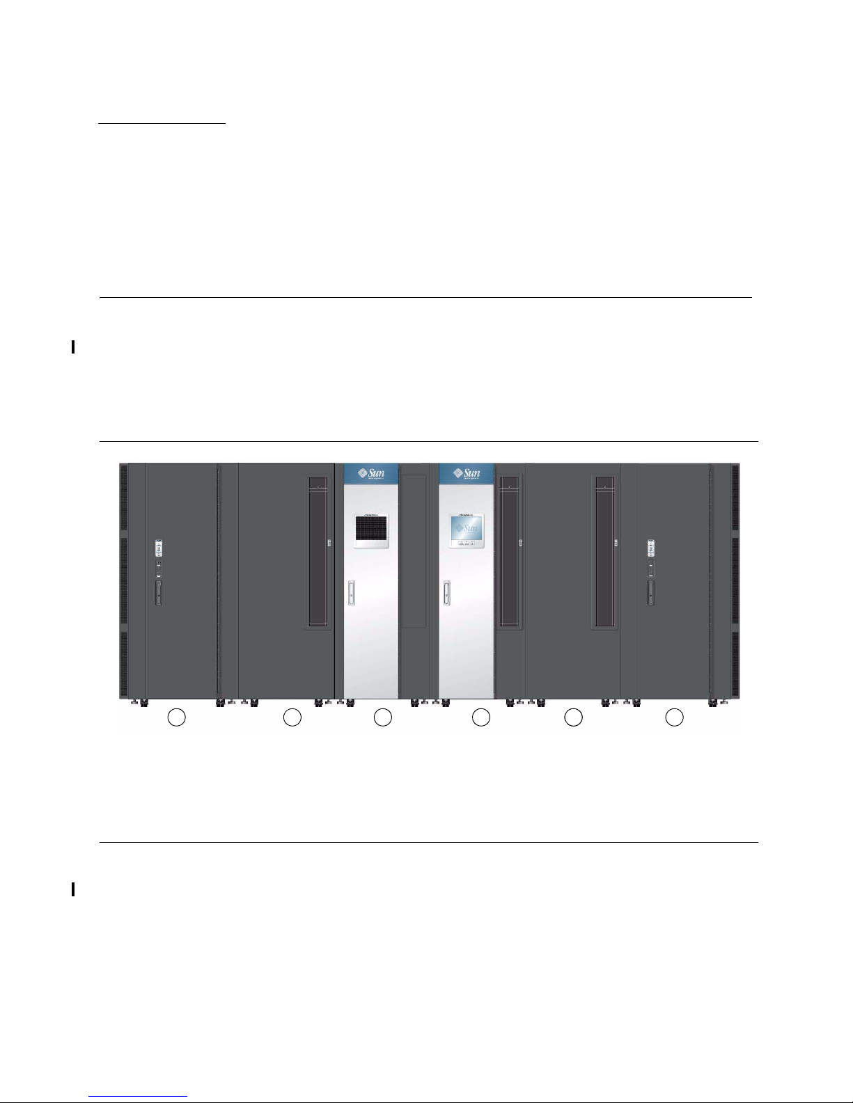
FIGURE 1-1 SL3000 Modular Library System—Configu
1. Base Module—Base
3. Cartr
(required—one per library)
2. Drive Expansion Module—DEM
ptional, must be installed to the left of the
(o
4. Access Exp
base module—one per library)
, components, and configurations.
ration Example
idge Expansion Module—CEM
(maximum of eight per library)
ansion Module—AEM
(maximum of two per library—required for the
Dual T
allBot feature)
This library offers customers the benefits of:
■ Storage capacity from 200 to 5,925 slots
■ Performance from 1 to 56 tape drives
■ Bulk cartridge loading capabilities from 234 to 468 cartridges (one or two AEMs)
■ Heterogeneous attachments using standard interfaces
■ Multiple library management software options and programs
316194102 • Revision: B 1
Modular Design
Modular Design
The SL3000 library maintains the fundamentals of a modular design that allows
customers the ability to meet the demands of rapidly growing and constantly
changing environments.
The SL3000 library was designed to:
■ Address medium to large open systems and entry-level mainframe markets.
■ Occupy a standard data center footprint with measurements of approximately:
Height
Depth
Length
198 cm (78 in.)
124 cm (49 in.)
From: 91.5 cm (36 in.) a single Bas
To: 782.4 cm (308 in.) Base, DEM, 8 CEMs, and covers; [7.8 m
e module; [0.9 m (3 ft)]
(25.7 ft)]
To: 965.2 cm (380 in.) Base, DEM, 8 CEMs, 2 AEMs, covers; [9.65
m (31.7 ft)]
A maximum configuration consists of 12 modules.
■ 1 Base module
■ 1 Drive expansion module
■ 8 Cartridge expansion modules
■ 2 Access expansion modules
See Chapter 3, “Site Planning” for specific details.
Modules
There are currently five types of modules in an SL3000 library:
■ Base module (Base) one, required
■ Drive expansion module (DEM)—maximum of one—on the left side of a base
module only
■ Cartridge expansion module (CEM)—maximum of eight (without conversion to
parking expansion modules)—
■ Parking expansion module (PEM)
robotics feature—
■ Access expansion module (AEM)
■ Single AEM provides bulk loading capabilities only.
■ Two AEMs provide bulk loading and a parking zone for the dual robotics feature.
■ Two AEMs are required for the dual robotics feature.
left and right ends of the library
left or right side
1
—must order two, one on each end for the dual
1
—one or two, on the ends of the library
1. You need either two parking expansion or two access expansion modules to support the
dual robotics feature. You can not mix and match PEMs with AEMs.
2 SL3000: Systems Assurance Guide • May 2010 Revision: B • 316194102

FIGURE 1-2 Bas
Modular Design
Base Module
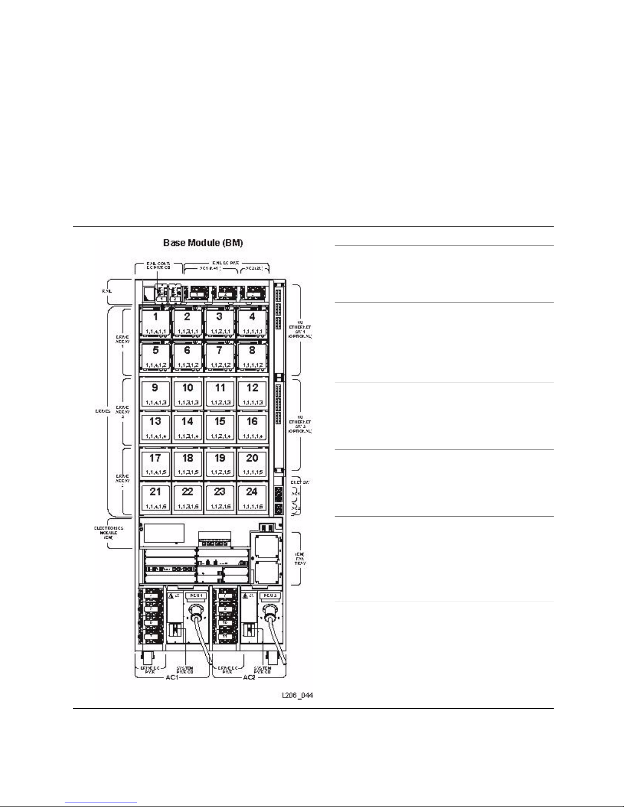
FIGURE 1-2 shows an example of the Base Module. This module provides the entry
level offering, which consists of a single frame and
other modules in the library. This module includes the power supplies, robotic units,
electronics control module, cartridge access port, storage slots, tape drives, and
operator controls.
One base module—
and only one—is required for every library installation.
On the front of this module is:
■ A single, 26 cartridge–dual magazine–cartridge access port (CAP).
■ A service door for library access.
■ A front panel with three LEDs: Library Active, Service Required, and Wait.
■ Plus an optional feature for a touch screen operator panel or perforated window.
e Module—Front View
Configurations
8 drive slots, CAP, perforated window (standard configuration)
Optional Configurations
16 drive slots, CAP, perforated window
24 drive slots, CAP, perforated window
8 drive slots, CAP, and Op
16 drive slots, CAP, and Operator panel or window
24 drive slots, CAP, and Operator panel or window
centralizes the infrastructure for all
erator panel or window
1.
Dimensions Measurement
Height 197 cm (77.625 in.) to
200 cm (78.63 in.) fully adjusted
Width 76.78 cm (30.23 in.) without covers
91.5 cm (36 in.) with cover
s
Depth 124 cm (49 in.)
Wei gh t Frame only: 361 kg (790 lb)
Service clearance
Front: 46 cm (18 in.) [allow 56 cm (22 in.)]
Rear: 81 cm (32 in.)
Both doors open
Side covers Width: 7.4 cm (2.9 in
Total: 262 cm (103 inches)
.) per side cover
Cooling clearance: 5 cm (2 in.)
Install: 91 cm (36 in.)
1.
Perforated windows are the standard offering. Arrays may displace an operator panel or window.
2.
Recommended cooling clearance.
3.
Required to install or remove the sides covers; they swing out and lift off of brackets.
3.
The Base module can contain up to 24 tape drives in any combination that the library
supports—see “Tape Drives” on page 24 for a list and description of these drives.
Physical capacity varies depend
ing on the configuration—see TABLE 1-1 on page 12.
2.
316194102 • Revision: B Chapter 1 Introduction 3
Modular Design
FIGURE 1-3 Bas
The minimum configuration includes one drive bay that can contain from 1 to 8 tape
drives. Two additional drive bays can be added to accommodate either 8 or 16 more
drives for a total of 24 drives.
Note – A
dding a second drive bay will displace from 55 to 66 cartridge slots; adding
a third drive bay will displace from 60 to 72 slots.
The rear door of the Base module allows access to the:
■ Electronics control module (ECM)
■ Power distribution units (PDUs) and DC power supplies (DCPS)
■ Tape d riv e s
■ Two 1-unit rack spaces (1 unit = 44.5 mm [1.75 in.]) not for customer use
e Module—Rear View Drawing
Description
Robotic rail power and HBS cards
■ DCPS 1 and 2 or 3
First drive array (top)
The first drive bay is standard.
Note:
Drive arrays are adde
d from the top ➪
down.
Second drive array (center)
Adding a second drive array displaces
55/66 data cartridge slots
Third drive array (bottom)
Adding a third drive array displaces
60/72 data cartridge slots
Electronics control module:
■ HBCR and HBT cards
■ MPU2 Fibre Channel card (not shown)
■ Two cPCI power supplies
■ Two cooling fans
■ Two p o wer s w itch e s (N+ 1 and 2 N )
Power distribution units (up to 2)
■ PDU 1 and PDU 2
4 SL3000: Systems Assurance Guide • May 2010 Revision: B • 316194102
Drive DC power supplies (up to 8)
■ DCPS 4 through 11
Drive Expansion Module
FIGURE 1-4 shows an example of the Drive Expansion Module (DEM). This module is
attached adjacent to the Base module on the left sid
expansion of tape drives and provides additional data cartridge capacity.
One drive expansion module—an
Its position is immediately to the left of the
On the front of this module is space for:
■ A service door for library access (standard)
■ A front panel with three LEDs: Library Active, Service Required, and Wait
■ A single, 26 cartridge-dual magazine, cartridge access port optional feature
■ Touch screen operator panel optional feature if not in the base (or window)
FIGURE 1-4 Drive E
Modular Design
e only. The DEM allows further
d only one—can be included in an installation.
centerline (left edge of the base module).
xpansion Module with a Base Module
Configurations
8 drive slots, perforated window
16 drive slots, perforated window
24 drive slots, perforated window
32 drive slots, perforated window
8 drive slots, CAP, perforated window
16 drive slots, CAP, perforated window
24 drive slots, CAP, perforated window
32 drive slots, CAP, perforated window
8 drive slots, CAP, and Ope
rator panel/Window/Arrays
1.
16 drive slots, CAP, and Operator panel/Window/Arrays
24 drive slots, CAP, and Oper
32 drive slots, CAP, and Oper
Dimensions
2
Measurement
ator panel/Window/Arrays
ator panel/Window/Arrays
Height 197 cm (77.625 in.) to
200 cm (78.63 in.)
Width
Module-only:
Base and DEM:
76.78 cm (30.23 in.)
168.3 cm (66.26 in.) with covers
Depth 124 cm (49 in.)
Wei gh t Frame only: 265 kg (584 lb)
Service clearance
Front: 46 cm (18 in.)
Rear: 81 cm (32 in.)
Both doors open
Side covers
3, 4, 5
262 cm (103 inches)
Cooling clearance: 5 cm (2 in.)
Install: 91 cm (36 in.)
1. Perforated windows are the standard offering. Arrays may displace an operator panel or window.
2. The dimensions of the DEM are the same as the Base module.
3. When installing additional modules, the covers are removed from the Base and replaced on the ends of
the last module in the string.
4. Required to install or remove the sides covers; they swing out and lift off of brackets.
5. This is the r
316194102 • Revision: B Chapter 1 Introduction 5
ecommended cooling clearance.

Modular Design
The DEM comes with slots to support up to 8 tape drives (standard).
Optional features allow the DEM to increase drive capacity from 16, to 24, and 32
additional tape drive slots. These features allow expansion up to a total of 56 tape
drives per library.
There is an additional power system integral to the DEM to support the additional tape
drives and two 1-unit rack spaces for vertically mounting auxiliary equipment, such as
Ethernet switches (not for customer use).
FIGURE 1-5 Rear View of the Drive Expansion Module
Description
First drive array (top)
The first drive bay is standard.
Note: Drive arrays are added from
the top ➪ down.
Second drive array
Adding a second drive array
displaces 55/66 slots
Third drive array
Adding a third drive array
displaces 60/72 slots
Fourth drive array
Adding a fourth drive array displaces
65/78 slots or all the slots on the rear wall
Power distribution units (up to 2)
■ PDU 3 and PDU 4
Drive DC power supplies (up to 8)
■ DCPS 15 through 22
Note: Physical capacity varies depending on the configuration—see TABLE 1-1 on page 12.
6 SL3000: Systems Assurance Guide • May 2010 Revision: B • 316194102

Modular Design
Cartridge Expansion Module
FIGURE 1-6 is the Cartridge Expansion Module (CEM) and provides additional
cartridge slot capacity and growth—no tape d
rives are present within this module.
A maximum of eight (8) CEMs are supported on a single library
module (required) and optional drive expansion module if installed.
Important:
■ As a best practice, the initial CEM should be installed to the right of a base module,
■ A balance of CEMs—to the left and to the right—provides for the most efficient
■ When using redundant robotic units, the addition of parking expansion modules in
Each CEM adds approximately 438 to 620 data cartridge slots to the library depending
on
FIGURE 1-6 Cartr
in addition to the base
then a second to the left of the drive expansion module. Then again to the right, and
the last one to the left. This method provides the best usage of the cartridge slots.
The exception is if an extra CAP is installed and physical capacity i
s less important
than having redundant CAPs. If redundant CAPs are required, install the CEM with
a CAP on the left. This assumes no DEM is installed. If one is installed, then place
the CEM on the right and install a CAP on the DEM.
operation. Cartridge expansion modules can be installed with up to 4 to the right
and up to 4 to the left. However, this increase in the amount of robotic travel results
in a decrease of overall library performance.
place of the CEMs or the use of access expansion modules is required at both ends of
the library.
the direction of growth (left or right) and options (CAP or no CAP).
idge Expansion Module with Base Module
Configuration (next to Base with 24 drive slots)
CEM (expanded left)
CEM with optional CAP (left)
CEM (expanded right)
CEM with optional CAP (right)
Dimensions Measurement
Height 197 cm (77.625 in.) to
200 cm (78.63 in.) fully adjusted
Width 76.76 cm (30.22 in.)
84.12 cm (33.12 in.) with cover
Depth 77.47 cm (30.5 in.)
Weight Frame only: 175 kg (385 lb)
Side covers
Side clearance
Service clearance
1
Cooling clearance: 5 cm (2 in.)
2
Install: 91 cm (36 in.)
None required
(Front and Rear)
Base Module | CEM
1. When installing additional modules, the covers are removed from existing modules and replaced on the ends
of the last module in the string.
2. Required to install or remove the sides covers; they swing out and lift off of brackets.
316194102 • Revision: B Chapter 1 Introduction 7

Modular Design
Parking Expansion Module
FIGURE 1-7 is the Parking Expansion Module (PEM). This module is the same as a
cartridge expansion module except with 6 columns of arrays (3 on the front wall and
3
on the rear wall) that are inaccessible. This allows the library to park a defective
robot without blocking access to cartridges for the other operational robot.
Notes:
1. Parking expansion modules must be installed as the last module in the string; on
both right- and left-sides. This allows a defective robot to be parked out of the way
of the operational robot, allowing operations to continue.
2. A PEM is a converted CEM. Conversion is done by changing an internal module ID
label that is shipped with the redundant TallBot feature.
3. The arrays do not need to be removed; this allows the customer to restore this
module to a CEM; however, any data cartridges in those arrays will be
4. Customers can order an optional CAP with a left expansion module; however, a
CAP on the right PEM is inaccessible.
FIGURE 1-7 Parking Expansion Module with Base Module
inaccessible.
PEM Next module (CEM/DEM/Base)
Parking Cartridge
Area Slots
Configuration
PEM (expanded left) 308 slots
PEM (expanded right) 312 slots
620 slots total
Always installed in pairs for redundant robotics.
Dimensions
1
Measurement
Height: 197 cm (77.625 in.) to
200 cm (78.63 in.) fully adjusted
Width: 76.76 cm (30.22 in.)
84.12 cm (33.12 in.) with cover
Depth: 77.47 cm (30.5 in.)
Weight: Frame only: 103.4 kg (277 lb)
Side covers:
Side clearance:
2
Cooling clearance: 5 cm (2 in.)
3
Install: 91 cm (36 in.)
Service clearance: None
Notes:
1. The dimensions of the PEM are the same as the cartridge expansion module.
2. When installing additional modules, the covers are removed from existing modules and replaced on the ends of
the last module in the string. PEMs must be the last modules in the string.
3. Required to install or remove the sides covers; they swing out and lift off of brackets.
8 SL3000: Systems Assurance Guide • May 2010 Revision: B • 316194102

Access Expansion Module
FIGURE 1-8 shows the optional Access Expansion Module (AEM), which provides:
■ Bulk loading and unloading of up to 234 cartridges at a time per module.
■ Non-disruptive robot maintenance through the use of a safety door (or “garage”
door), which sections off a defective robot from the other library modules.
A service representative can safely access the disabled robot through the AEM access
door while the library remains online. If redundant robots are installed, the library
can continue normal operations through the remaining functional robot.
The library can have either one or two AEMs.
1. With one AEM, installed on either end of the string (recommend the left side*), the
library supports bulk load and unload features only.
* Note: Installing the AEM on the left side gains an additional 104 cartridge slots
from the previous module.
2. With two AEMs, one installed on each end of the library string, the library supports
both bulk load/unload, and the non-disruptive, redundant, robotic features.
Note – AEMs and PEMs cannot be installed in the same library.
FIGURE 1-8 Access Expansion Module—Front View
Modular Design
Configurations
Expanded left 234 slots
Plus 104 slots from the
previous module
Expanded right 234 slots
Single AEM = Bulk load capabilities only
Dual AEMs = Bulk load and redundant robotics feature.
Dimensions Measurement
Height: 197 cm (77.625 in.) to
200 cm (78.63 in.) fully adjusted
Width: 91.5 cm (36.0 in.) without covers
99 cm (39 in.) with covers
Depth: 77.47 cm (30.5 in.)
Weight: Frame only: 204.2 kg (450 lb)
Side covers
Side clearance
Notes:
1. When installing additional modules, the covers are removed from
existing modules and replaced on the ends of the last module in
the string.
2. Required to install or remove the sides covers; they swing out and
lift off of brackets.
1
Cooling clearance: 5 cm (2 in.)
2
Install: 91 cm (36 in.)
316194102 • Revision: B Chapter 1 Introduction 9

Addressing
Addressing
The modules of the library consist of walls, columns, and rows that house cartridges,
tape drives, cartridge access ports, and robotic units.
The SL3000 uses five parameters separated by comma's to indicate locations or
esses in the library. These parameters are < L, R, C, S, W >, which is:
addr
■ Library (L) = Library number
■ Rail (R) = Rail
■ Column (C) = Horizontal location in the library
■ Side (S) = Walls
■ Row (W) = Vertical location in the library
Library and Rail
The library and rail parameters do not apply to this library and are constants.
These parameters will always be 1 (one).
Columns
There are two types of columns that provide the
horizontal locations for components;
such as data cartridges, tape drives, and cartridge access ports:
■ Positive numbered are to the right of the centerline*
■ Negative numbered are to the left of the centerline*
Note – Ce
nterline* is the left-edge of the Base module.
Columns are numbered from left to right; tape drive arrays have 4 columns per
dule; media or data cartridge arrays have 6 columns per module.
mo
Side
There are two types of walls in the SL3000 library:
■ Front wall parameter is 1
■ Rear wall parameter is 2
Rows
Rows provide the
down from 1 (top) to 52 (bottom).
See Appendix A, “Addressing” for specifics about the various addressing schemes
used with the SL3000 Library.
vertical locations for components and are numbered from the top
10 SL3000: Systems Assurance Guide • May 2010 Revision: B • 316194102

Physical Capacities
Physical Capacities
The SL3000 is scalable, with physical storage capacities from 200 to 5,925 storage slots.
TABLE 1-1 on page 12 provides detailed physical capacities for each module type.
To calculate the total accessible physical storage slots for a configuration, start with the
standard configuration slot count, outlined with a heavy border, and then make the
appropriate adjustments for options and positioning.
Following are some examples:
■ Base Module with operator’s panel, a module installed on the right, and three total
drive arrays:
320 + 0 + 13 – 55 – 60 = 218
■ DEM, a module installed on the left, window arrays, a CAP, and four drive arrays:
410 + 88 + 23 – 77 – 66 – 72 – 78 = 228
■ CEM installed to the left of CenterLine, a module installed on the left, and a CAP:
516 + 104 – 78 = 542
■ PEMs (always installed in pairs), one with a CAP, one without:
308 + 312 – 78 = 542
■ AEMs are considered CAPs and do not include any capacity for the library.
To calculate the final accessible storage capacity, select the slot counts for each module,
then add them together to reach the total slot count for the library with the
configuration selected.
In addition, the SL3000 features Capacity on Demand. This feature allows you to:
■ Pay for only the capacity you actually use, then
■ Expand capacity—with minimal disruption—when you need it.
See “Capacity on Demand” on page 160 for details about installing and managing
library storage capacity.
316194102 • Revision: B Chapter 1 Introduction 11
Physical Capacities
TABLE 1-1 Accessible Physical Slot Count Per Module
Standalone
or
Adjacent Module
Installed on the:
Position-
Module Options Right Left Total Count
Independent
Base Module
Standard (with viewing window),
standal
one
320
+13 +88
With operator’s panel +0
With window storage arrays +23
With second drive array -55 -66
With third drive array -60 -72
Drive Expansion Module (DEM)
Standard (with viewing window
— 410 +88
and no CAP)
With window storage arrays — +23
With CAP — -77
With second drive array — -55 -66
With third drive array — -60 -72
With fourth drive array — -65 -78
Cartridge Expansion Module (CEM)
Standard (no CAP), to the left of
C
enterLine
Standard (no CAP), to the right of
C
enterLine
516 +0 +104
620 +0 +0
With CAP -78
Parking Expansion Module (PEM)
Standard (no CAP), to the left of
C
enterLine
Standard (no CAP), to the right of
enterLine
C
— 308
— 312
With CAP — -78
Access Expansion Modu
le (AEM)
Standard to the left of CenterLine — 0 +104
Standard to the right of CenterLine — 0
Total accessible storage slot count
12 SL3000: Systems Assurance Guide • May 2010 Revision: B • 316194102

Power Options
Power Options
SL3000 libraries require that the customer select one of the following, single phase,
AC
power options for the Base and Drive Expansion modules, these are:
■ 120 VAC, 50/60 Hz, at 20 Amps
(range: 100–127 VAC, 47–63 Hz, 16 Amps)
limited support for T9840 and T10000 drives; no redundant TallBot support
■ 240 VAC, 50/60 Hz, at 30 Amps
(range: 200–240 VAC, 47–63 Hz, 24 Amps)—full featured
AC Power Configurations
SL3000 libraries have two power configurations:
■ N+1, offering DC power redundancy only.
■ 2N, offering both AC and DC power redundancy.
Power Redundancy
The SL3000 provides full redundancy for tape drives, robotics units, and electronics.
The following redundancy options are available:
■ N+1—One AC PDU, with one extra DC power supply for DC power redundancy.
This is the standard power configuration for the SL3000. This configuration requires
at least a 20
■ 2N—Two PDUs for AC redundancy; each PDU has a set of DC power supplies
(N
DC power supplies). This configuration requires a second, separate customer
Amp circuit breaker at the customer’s branch service panel.
power source.
■ 2N+1—Two PDUs for AC redundancy; each PDU has extra DC power supplies for
N+1 redundancy for each PDU. The second PDU does not have N+1 for the TallBot.
N+1 Power Configuration—Standard
N+1 is the standard power configuration for the libraries and contains one system
power distribution unit (PDU).
Note – The N+1 power configuration offers DC power redundancy only.
The N+1 system PDU connects to the customer’s branch circuit and requires at least a
20 Amp circuit breaker at the customer’s branch service panel.
2N Power Configuration—Optional
The optional 2N power configuration contains two system power distribution units
(PDU_1 and PDU_2) and requires a second—separate—customer power source.
Note – The 2N power configuration offers both AC and DC power redundancy.
316194102 • Revision: B Chapter 1 Introduction 13
Power Options
AC Power Cables
TABLE 1-2 lists the cables available from StorageTek or qualified electricians, which
must be or
Keep in mind that you must order:
■ N+1: One power cord for each, the Base module and DEM if installed.
■ 2N: Two power cords for each, the Base module and DEM if installed.
dered for the appropriate power configuration.
TABLE 1-2 P
Power Source Description
120 VAC/ 20A US / Japan 20 A L5-20P L5-20R
240 VAC / 30A US 30 A L6-30P L6-30R
240 VAC / 30A International 30 A 330P6W L6-30R
ower Cable Part Numbers and Descriptions
Circuit
Breaker
Connector Type
Wall Library Item X-Option
Robotic DC Power Configurations
Each Base module ships with two 1200 Watt—load sharing—DC power supplies for the
robotic units; the location of these supplies determines if it is an N+1 or 2N
configuration.
See FIGURE 1-3 on page 4 for the location of these power supp
Base Module).
Electronic Control Module DC Power Configurations
Power Cord
Length/Type
3.7 m (12 ft)
12 AWG
3.7 m (12 ft)
12
AWG
4 m (13 ft)
HAR
Part Numbers
419813801
419813701
419813601
XSL3000-
PC20110-Z
XSL3000-
PC30220-Z
XSL3000-
0220Z
IPC3
lies (on the top of the
Dual 200 Watt cPCI power supplies distribute power to the electronics control module,
which are located below the HBT card, supporting either an N+1 or 2N configuration.
■ For an N+1 configuration, two cPCI power supplies are installed on the left.
■ For a 2N configuration, one cPCI power supply is installed on each side.
■ For a 2N+1 configuration, two cPCI power supplies are installed on each side.
14 SL3000: Systems Assurance Guide • May 2010 Revision: B • 316194102
Power Options
Single Drive Type DC Power Configurations
This library uses 1200 Watt—load sharing—DC power supplies (DCPS) for distribution
of +48 VDC power for the tape drives acr
oss a power grid.
Each Base module and DEM ship with two (2
number of tape drives ordered, additional power supplies may be required.
To determine the number of supplies required, you must determine:
■ Power configuration (120 VAC or 240 VAC)
■ Tape drive type (T10000, T9840, or LTO)
■ Number of drives
See TA BLE 1-3 on page 15 to help determine the number of supplies
■ This table shows only the installation of a single drive type.
■ See Mixed Drive Types on page 16 when mixing tape drives in the same module.
TABLE 1-3 T
Module
Ty
pe
ape Drive DC Power Supply Requirements
PDU
Typ e
Base 120 VAC
DEM 120 VAC
) DC power supplies. Depending on the
required.
Maximum Number of Drive Types Power Configuration
N+1 & 2N
T10000 T9840 LTO N+1 2N
Total
1 – 8 1 – 7 1 – 16 1 + 1 = 2 1 + 1 = 2 2 + 2 = 4
9 – 13 8 – 12 17 – 24 2 + 1 = 3 2 + 2 = 4
3 + 3 = 6
1 – 8 1 – 7 1 – 16 1 + 1 = 2 1 + 1 = 2 2 + 2 = 4
9 – 16 8 – 14 17 – 32 2 + 1 = 3 2 + 2 = 4 3 + 3 = 6
Base 240 VAC
DEM 240 VAC
Note: The bas
e and drive expansion modules each come with 2 DC power supplies as standard.
1 – 12 1 – 1 1 – 24 1 + 1 = 2 1 + 1 = 2 2 + 2 = 4
13 – 24
12 – 22 N/A 2 + 1 = 3 2 + 2 = 4 3 + 3 = 6
N/A 23 – 24 N/A 3 + 1 = 4 3 + 3 = 6 4 + 4 = 8
1 – 12 1 – 11 1 – 25 1 + 1 = 2 1 + 1 = 2 2 + 2 = 4
13 – 24 12 – 22 26 – 32 2 + 1 = 3 2 + 2 = 4 3 + 3 = 6
25 – 32 23 – 32 N/A 3 + 1 = 4 3 + 3 = 6 4 + 4 = 8
316194102 • Revision: B Chapter 1 Introduction 15

Power Options
Mixed Drive Type DC Power Configurations
When mixing tape drive types in a library, you need to calculate the total
Wat t consumption for the selected
1. Determine the number of tape drives for each drive type.
drives. To do this:
2. Multiply that by the Watts per
drive for each drive type TABLE 1-4.
3. Add the total Watts for all drive types.
4. Use TA BLE 1-5 to compare Watts to PDU type.
5. Use TA BLE 1-6 to determine the number of DC power supplies needed.
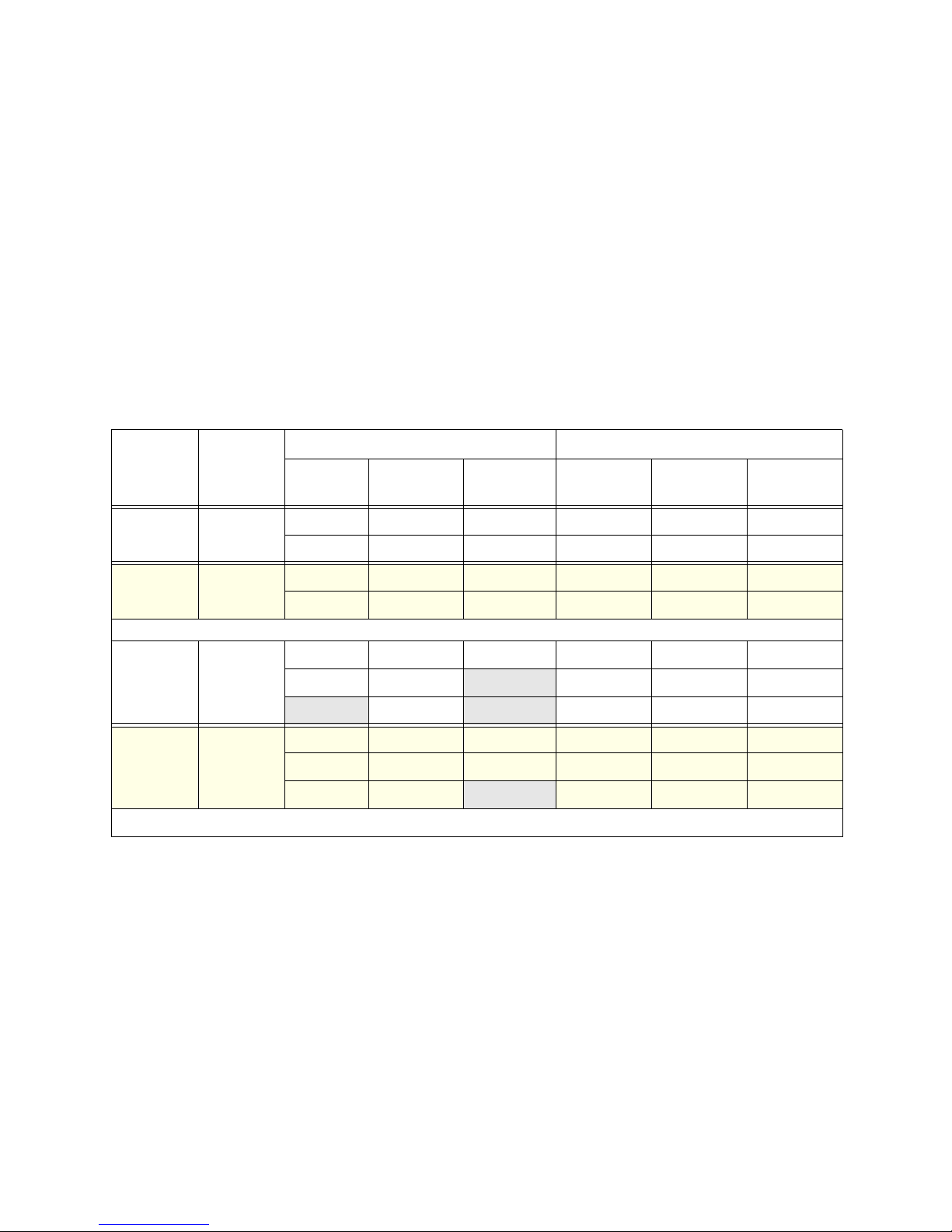
TABLE 1-4 Wa tts P er Dr i ve
Watts Used by
Drive Type
Each Drive
T9840 123.9 7 11
T10000 115.2 8 12
LTO 56.9 16 25
Drives supported by a Power Supply
120 VAC 240 VAC
TABLE 1-5 Available Watts Per Module
Watt Limitation per Supply
120 VAC 240 VAC
Module Type PDU Type
120 VAC 1553 951 W 1426 W
Base
240 VAC 3234
120 VAC 1868
DEM
240 VAC 4313
Watts Available for
Tape Drives
TABLE 1-6 DC Power Supplies Per Module
Power Configuration
PDU Type Total Watts
1 - 951 1 + 1 = 2 1 + 1 = 2 2 + 2 = 4
120 VAC
952 - 1,868 2 + 1 = 3 2 + 2 = 4 3 + 3 = 6
1 - 1,426 1 + 1 = 2 1 + 1 = 2 2 + 2 = 4
240 VAC
1,427 - 2,852 2 + 1 = 3 2 + 2 = 4 3 + 3 = 6
2,853 - 4,278 3 + 1 = 4 3 + 3 = 6 4 + 4 = 8
Add for
T
otal Watts
Per Type
Drive
Typ e
# of
Drives
Multiplied By
Watts
TABLE 1-4)
(
16 SL3000: Systems Assurance Guide • May 2010 Revision: B • 316194102
N+1 2N N+1 & 2N Total
Power Configuration
Total Wa t t s
TABLE 1-6)
(
Option
(N
+1 or 2N)
PDU Type
TABLE 1-5)
(
DCPS
(TABLE 1-6)

TABLE 1-7 provides an example about how to calculate mixed drive types in both the
Base module and drive e
TABLE 1-7 Mixed
Power Options
xpansion module:
Drive Type Power Configuration—Calculation Example
Add for
# of
Drive Type
T10000 6 115.2 691.2 N+1 120 VAC not
T9840 6 123.9 743.4
Base
LTO 8 56.9 455.2 1889.8 N+1 240 VAC 2 + 1 = 3
T10000 4 115.2 460.8 N+1 120 VAC 2 + 1 = 3
T9840 4 123.9 495.6 1184 2N 120 VAC 2 + 2 = 4
DEM
LTO 4 56.9 227.6 N+1 240 VAC 2 + 1 = 3
Driv
Multiplied By
TABLE 1-4)
es
(
To
tal Watts
Per Type
Tot a l W a t t s
TABLE 1-6)
(
Option
Power Configuration
PDU Type
(TABLE 1-5)
2N 120 VAC supported
2N 240 VAC 2 + 2 = 4
2N 240 VAC 2 + 2 = 4
(TABLE 1-6)
Notice in the above example, the:
■ Base module requires a 240 VAC PDU with either an N+1 or 2N power option.
■ DEM requires either a 120 VAC or 240 VAC PDU with either an N+1 or 2N option.
■ Remember, you cannot mix 120 VAC with 240 VAC PDUs within the library.
What you need to order:
Minus 2 (-2)Additional
Module PDU Type Option DC Redundancy
DCPS
DC
PS
120 VAC
Base
240 VAC
120 VAC
DEM
240 VAC
N+1
2N
N+1 2 + 1 = 3 1 1
2N 2 + 2 = 4 2 2
N+1 2 + 1 = 3 1 1
2N 2 + 2 = 4 2 2
N+1 2 + 1 = 3 1 1
2N 2 + 2 = 4 2 2
Remember, two DC power supplies are shipped standard for the tape drives, robotics,
and electronics control module in the Base module.
Two DC power supplies are shipped standar
d for the tape drives in the drive
expansion module.
You only need to order additio
nal DC power supplies to support the type and number
of tape drives for the selected configuration.
316194102 • Revision: B Chapter 1 Introduction 17

Electronics Control Module
Electronics Control Module
All of the electronics, control, and host connectivity is located in the electronics control
module (ECM). The ECM is located in the rear of the Base module.
FIGURE 1-9 Electr
onics Control Module
HBCR Card
1. RS-232 serial port (reserved)
2. RS-232 serial port, CSE connection
(Command Line Interface—not customer accessible)
3. Port 2B—Primary Port—Ethernet 10/100 Base-T
HBT Card
7. RS-232 serial port (reserved)
8. RS-232 serial port, CSE connection
(Command Line Interface—not customer accessible)
9. RSVD port—Ethernet 10/100 Base-T (reserved)
4. Port 2A—Dual TCP/IP—Ethernet 10/100 Base-T
5. Port 1B—Ethernet 10/100 Base-T (reserved)
6. Port 1A—Ethernet 10/100 Base-T (reserved)
HBCR LEDs HBT LEDs
■ Active = Always lit during operation
■ Standby = Inactive
■ Fault = Indicates the controller detected a fault
■ Eject OK = Inactive
Notes:
■ The ECM also ships with an optional MPU2 or PUA card for Fibre Channel interface connections.
■ This card is not shown, but is installed below the HBCR card.
■ An HBCR library controller is included with the SL3000.
■ Active = Always lit during operation
■ Standby = Inactive
■ Fault = Indicates the controller detected a fault
■ Eject OK = Inactive
18 SL3000: Systems Assurance Guide • May 2010 Revision: B • 316194102
Robotic Units
Robotic Units
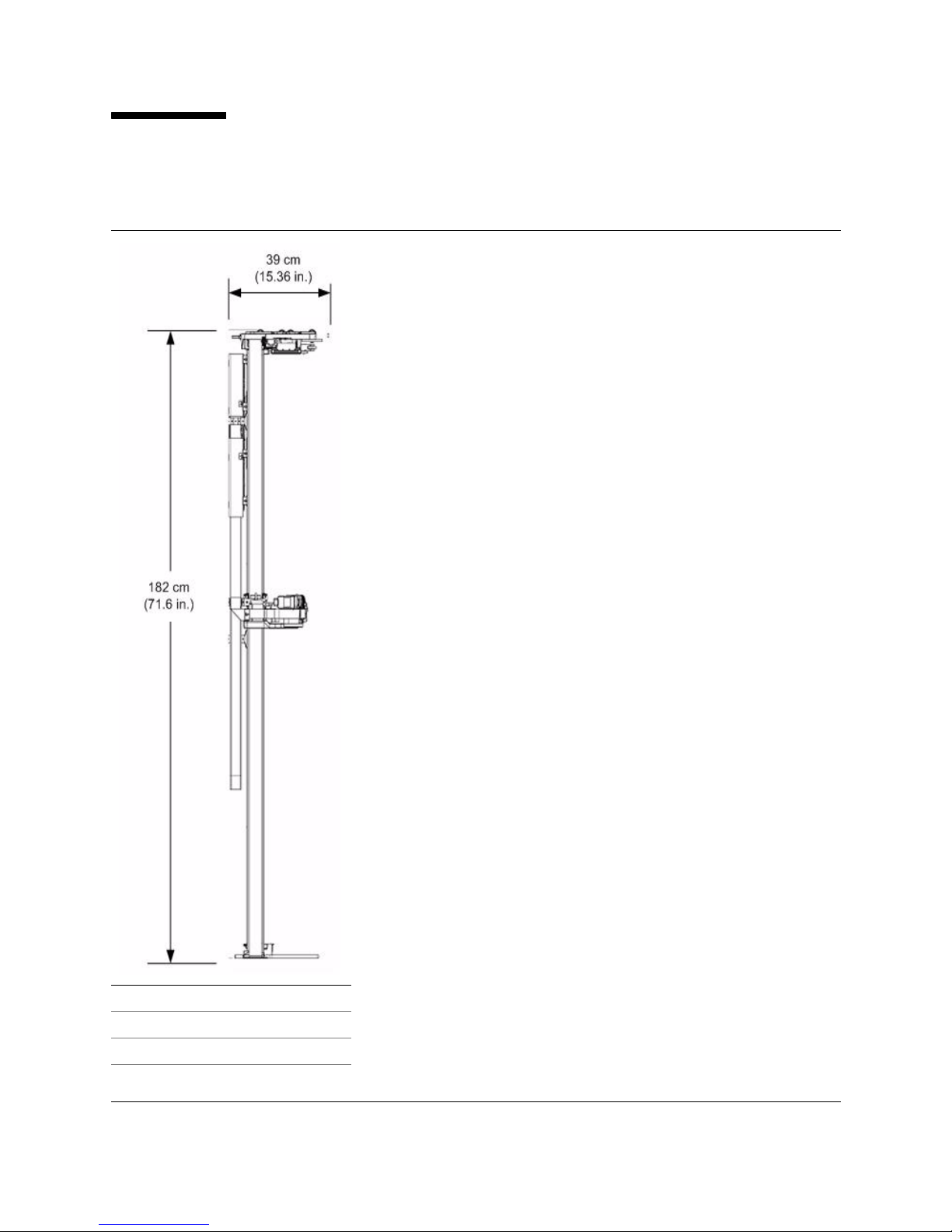
FIGURE 1-10 TallBot
Height 182 cm (71.6 in.)
Width 30 cm (11.84 in.)
Depth 39 cm (15.36 in.)
Wei gh t 8.6 kg (19 lb)
The robotic unit in an SL3000 library is called a TallBot. Each
library can have either one (standard) or two (redundant)
TallBots called “Dual Bots” or Dual Robotics.”
TallBots are responsible for the movement and cataloging—or
auditing—of cartridges throughout the library.
TallBots are driven along two extrusions
rear wall of the library; one rail at the top and one rail attached
to the floor. Each module contains pre-installed, segmented
extrusions.
Two copper strips are inserted into the top extr
provide both a power and a signal path for TallBot operation.
■ Power comes from +48 VDC, 1200 Watt, load sharing supplies.
■ Signals are received and transmitted between the TallBots and the
library controller (HBCR card).
■ A Rail Power Enable module is installed as a safety circuit for rail
power.
Gears on the TallBot motors mesh with molded plastic tracks
that are installed within the extrusions.
Handling of the cartridges by the TallBots include:
■ Retrieving cartridges—GET operation—from the CAP or slot
■ Inserting cartridge—PUT operation—into a CAP or slot
■ GETs and PUTs of cartridges to and from wall slots
■ Mounts and dismounts of cartridges to and from tape drives
TallBots contain a bar-code scanner that:
■ Reads the configuration blocks in each module during library
initialization
■ Targets on cartridge storage/CAP slots and tape drives
Targets are shaped |\| similar to an “N”.
■ Identifies volume serial numbers (VOLSERs) of cartridges
during CAP entries and Audits.
VOLSERs are read during audits and CAP entries only. After
that, cartridges are assigned locations within the library—slots.
During GET operations, the library uses the slot locations of the
rtridges to complete the required task.
ca
Redundant TallBot—Dual Bot operation of
■ Increases the speed for robotic operations
■ Backs up robotic operation in case one should fail
This option requires 200—240 V
AC, 2N power and parking
expansion modules or the access expansion modules at each end
of the library. A defective TallBot will take itself offline and
moves or is pushed into one of these modules, allowing the
library to continue operations with one TallBot until time can be
scheduled to replace the defective TallBot.
—called rails—on the
usion that
fers an option that:
316194102 • Revision: B Chapter 1 Introduction 19
Cartridge Access Ports
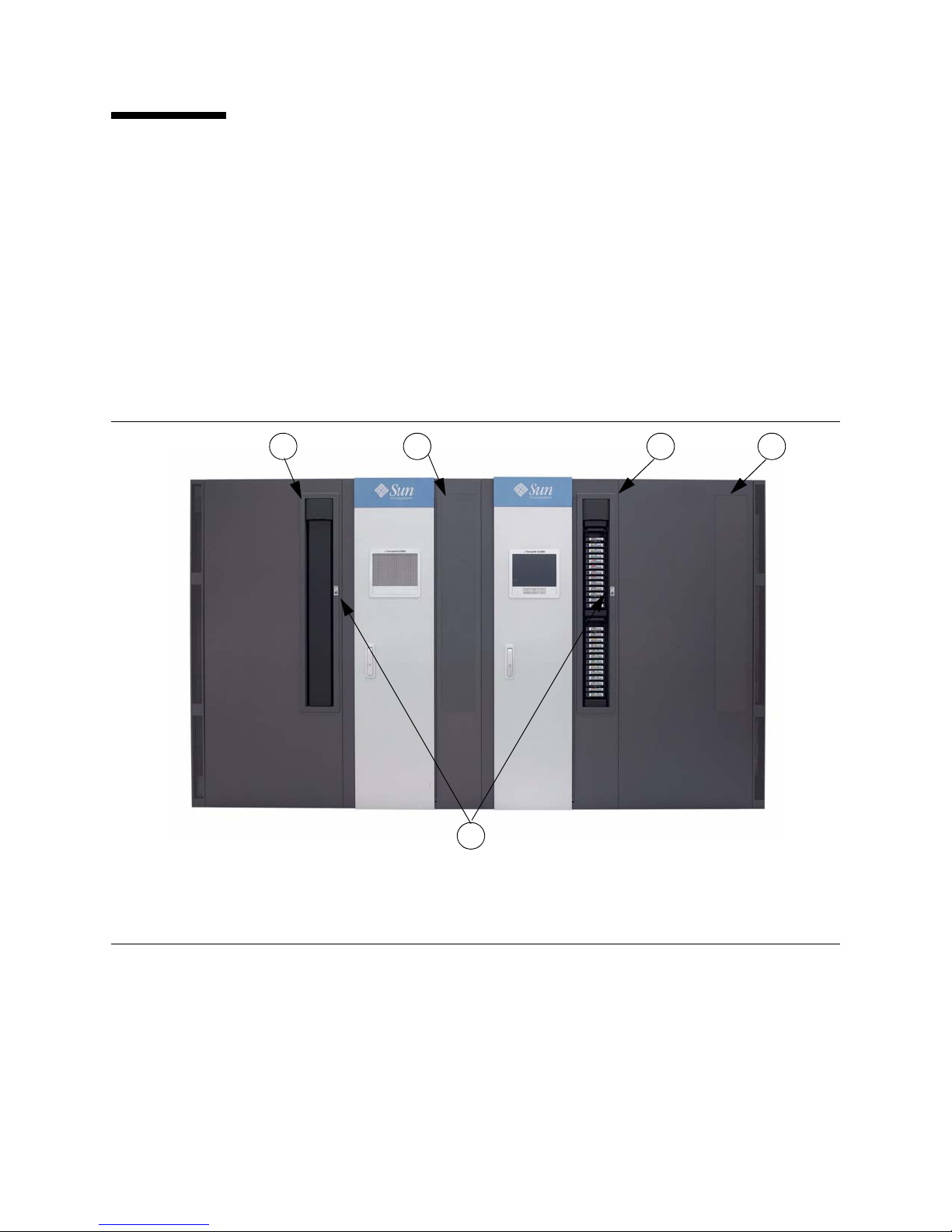
1 2 1 2
3
Cartridge Access Ports
The cartridge access port—CAP—is a vertically-mounted, rotating cylinder with two
removable 13-slot magazines (26 slots total).
■ The Base module comes with a CAP as a standard feature.
■ Drive and Cartridge expansion modules have an optional feature to contain a CAP
for a maximum of up to 10 standard (rotational) CAPs per SL3000 library.
Note – A
CAP in the right-side Parking Expansion Module is not accessible and
should be unplugged.
Each CAP comes with a small keypad including indicators and a us
operate that specific CAP.
FIGURE 1-11 Car
er interface to
tridge Access Port and Key Pad
1. Cartridge access ports (rotational CAPs)
2. Blank covers. When a CAP is not ins
This can always be upgraded in the future to include a CAP.
3. Keypad and indicator us
er interface.
Best Practices:
■ If partitioning, the recommendation is to install enough CAPs to provide at least one
CAP for each partition. This allows each partition to contain its own, dedicated CAP.
■ CAP control is split down the centerline. Make sure there is a left- and right-side
CAP to support the library. If a CAP encounters a failure, all CAPs following that
one will be unusable until the defective CAP is serviced. For this reason, the
recommendation is to install CAPs in a balanced fashion around the centerline.
20 SL3000: Systems Assurance Guide • May 2010 Revision: B • 316194102
talled, a blank cover is installed.
Cartridge Access Ports
Bulk Load CAPs
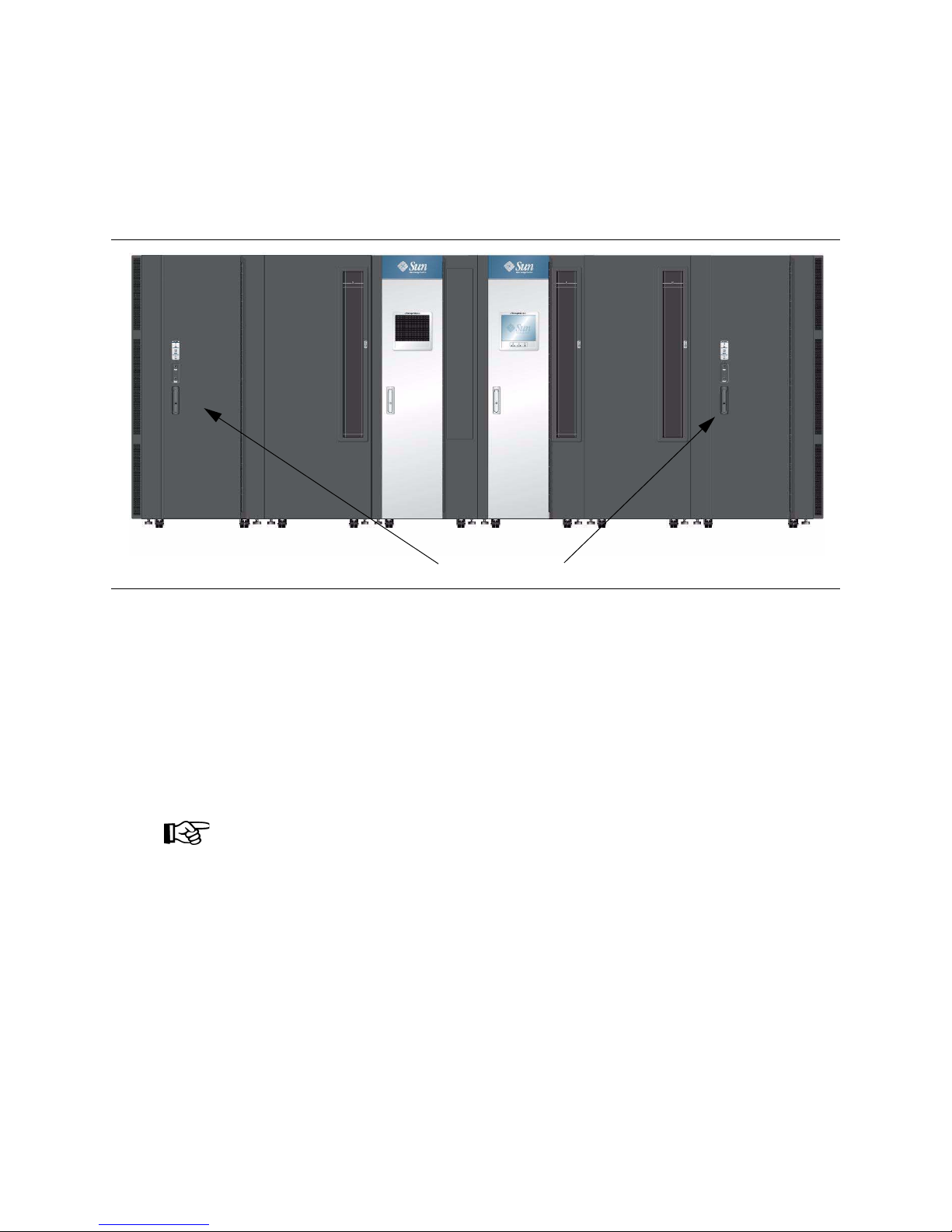
Bulk Load Cartridge Access Ports
The Access Expansion Modules have the ability for the customer to add cartridges in
bulk, up to 234 cartridges on each side,
without disrupting library operations.
FIGURE 1-12 Bul
Best Practices:
When entering and ejecting cartridges in smaller quantities, use the smaller rotational
CAPs to complete the job. These CAPs are easier to use and take less time to audit than
the larger AEM bulk load CAPs.
k Load CAPs—Access Expansion Modules
Although, operation of the cartridge acces
s port does not directly affect the
performance of the library, here are some guidelines that can help with the operation:
■ Whenever possible, enter cartridges through the cartridge access ports.
■ When planning the workloads, place applications that require significant enters and
ejects adjacent to the CAP magazines.
Tip:
Place labels outside on the library wall indicating
which CAP and which magazine gets
what type of cartridge. See “CAP Labels” on page 22.
■ Insert cartridges with the correct orientation:
■ Fully seated and laying flat within the slots
■ Parallel to the floor
■ Hub-side down
■ Barcode label pointing out and below the readable characters.
316194102 • Revision: B Chapter 1 Introduction 21

Cartridge Access Ports
CAP Labels
FIGURE 1-13 Cartridge Access Port Labels
Labels are provided for the customer to identify the
cartridge access ports. These labels include:
■ Left (L) and Right (R) SCSI labels
■ Sequential numbered labels for HLI
■ Create your own labels, which allows the customer to
write on the label to identify the CAPs as they want
22 SL3000: Systems Assurance Guide • May 2010 Revision: B • 316194102

Cooling
Cooling
Cooling within the SL3000 is divided into three areas:
■ Library (Electronics control module)
■ Tape d riv e s
■ DC power supplies
Library Electronics Control Module
There are two (2) fans located to the right of the electronics control module that
provide cooling for the electronics in the library. Air is drawn from the sides of the
library and flows through the fans to the rear of the library.
■ These fans are monitored by the HBCR card for proper operation.
■ An amber Fault indicator is on the fan assembly to indicate a failure.
While there are two (2) dedicated fans, one (1) fan is sufficient to provide adequate
cooling for the library and the electronics. Nevertheless, since the fans can be replaced
without interfering with library operations, it is best to replace a defective fan when it
is detected.
Tape D rives
Each tape drive tray contains a fan for drive cooling. Power for the fans is supplied
through the tape drive’s power converter card. Air is drawn from the front of the drive
and flows through the fan to the rear of the drive/library.
DC Power Supplies
Each 1200 Watt DC power supply contains a fan that pulls air from the library, through
the rear of the supply, and out the rear of the library.
316194102 • Revision: B Chapter 1 Introduction 23

Tape Drives
Tape Drives
TABLE 1-8 lists the supported tape drives, interfaces, and media types for the
SL3000 library.
TABLE 1-8 Suppo
Vendor Drive Type
StorageTek T9840C
HP
rted Tape Drives
T9840D*
*Encryption feature
T10000A*
T10000B*
*Encryption feature
LTO 3
LTO 4*
LTO 5*
2
Interface Type3 Media
Fibre Channel
FICON
9840
Vol Sa fe ca pa bl e
ESCON
2 Gb/4 Gb
Fibre Channel
T10000 Standard,
Sport, and VolSafe
FICON
LTO 3 , LTO4, an d LTO 5
Fibre Channel
WORM (L
LTO 2 ( read-on l y )
T)
*Encryption feature
IBM
LTO 3
LTO 4*
LTO 5*
Fibre Channel
LTO 3 , LTO4, an d LTO 5
WORM (LT)
LTO 2 ( read-on l y )
*Encryption feature
Notes:
1. StorageTek T9940 tape drives are not suppor
ted.
2. The Quantum SDLT 600 and DLT-S4 tape drives are not supported.
3. The parallel version of the small computer system i
nterface (SCSI) is not a supported connection.
4. LTO 2 media is supported for backward compatibility of LTO products (data migration).
4
4
Plus future releases of the above tape dri
See Appendix C, “Tape Drives and Media” for more information.
24 SL3000: Systems Assurance Guide • May 2010 Revision: B • 316194102
ve technologies, media, and interfaces

Tape Drives
Drive Tray
A single universal drive tray accommodates the different tape drives and interfaces.
The targeting system is the same as the other StorageTek SL-series libraries
(SL500 and SL8500); therefore, the tape drive automation bezels ar
e identical.
The drive trays, however
Instead of a single layer tray, the S
■ Power supply and connections are on the top, and the
■ Tape drive is under the power supply.
FIGURE 1-14 SL3000
Tape Drive Trays
Measurements:
■ Height: 16.5 cm (6.5 in.)
■ Width: 16.5 cm (6.5 in.)
■ Depth: 49.5 cm (19.5 in.)
, are different.
L3000 drive trays have two layers:
Each tray slides into a drive bay located w
A drive array can be removed to expand the cartridge capacity, or installed to increase
drive capacity.
tape
Internal power supply cards and cabling are unique depending on the drive-type and
interface within the
Cabling to the drive itself is at the rear of th
through the strain relief system. Cabling access is allowed for both under-floor and
ceiling routed cables.
316194102 • Revision: B Chapter 1 Introduction 25
ithin an 8-drive array.
drive tray.
e drive tray and library, then routed

Interfaces
Interfaces
SL3000 libraries support several types of interfaces for a variety of uses and platforms:
■ Host connectivity and library management
■ Service
■ Monitoring
Host Connectivity
There are two types of host connections to the library:
■ Small computer system interface (SCSI)
■ Ethernet (TCP/IP) using 10/100 Base-T and CAT-5 cables.
Important:
When implementing a new library into a network
customer, system and network administrators, and StorageTek representatives work
closely together to define the configuration and connection.
2
over a physical Fibre Channel interface, or
, it is strongly recommended that the
The design of the SL3000 library allows connection to either
Fibre Channel or Ethernet
environments. This design allows for several combinations of a host interface in both
partitioned and non-partitioned configurations.
■ In a non-partitioned configuration, the library can use only one (1) interface
type—either Fibre Channel or Ethernet (a second Ethernet connection can be used to
access StorageTek Library Console)
■ In a partitioned configuration, the library can use both interface types.
The library may have only SCSI partitions, only Ethernet partitions, or a
combination of both—u
Addressing between these two h
■ Ethernet hosts use a host library interface -panel, row, column (HLI-PRC)
p to a total of
ost connections varies:
eight (8) partitions.
numbering scheme.
■ SCSI hosts expect a sequential element numbering scheme with each element type
(slots, tape drives, and CAPs) given its own sequential range.
SCSI Media Changer-3 (SMC-3) is su
pported.
SCSI
The SL3000 library uses the small computer system interface (SCSI) protocol and
command set over a physical Fibre Channel (FC-SCSI) connection.
There are two optional Fibre Channel cards that provide connection to the library:
■ MPU2 = Single port connection (older availability)
■ PUA = Dual port connection (newer model containing two ports)
2. SCSI protocol and command set over a physical Fibre Channel interface.
26 SL3000: Systems Assurance Guide • May 2010 Revision: B • 316194102

Interfaces
Note – The StorageTek implementation of Fibre Channel conforms to:
■ American National Standards Institute (ANSI), and
■ National Committee for Information Technology Standards (NCITS)
Supported topologies include:
Switched Fabric: This topology is recommended for the library.
A switched fabric provides dynamic inter-connections between nodes and multiple,
simultaneous Fibre Channel connections for the network. If the library is connected
to a Fibre Channel switch or fabric-capable host, it configures itself as a switched
topology and can support up to 16 million ports logged into the fabric.
Arbitrated Loop: While the library supports the arbitrated loop topology, this connection
scheme is not recommended for new or future implementations. StorageTek does not
recommend the arbitrated loop connection by setting Hard ALPAs (Arbitrated Loop Physical
Addresses).
Arbitrated Loops provide multiple connections for devices that share a single loop
and allows only point-to-point connections between an initiator and target during
communications. An arbitrated loop can connect only up to 126 ports.
Refer to the SL3000 Interface Reference Manual PN 31619520x for more information. This
manual contains information about the small computer system interface command set
plus information about Fibre Channel operations, command implementations,
topologies, cables, and connectors.
TCP/IP
The library can also use TCP/IP protocol over an Ethernet physical interface,
(CAT-5, Ethernet, 10/100 BaseT cable) to manage and communicate with the host and
library management applications. To connect to and communicate with the library, this
interface enables both:
■ Open system platforms with ACSLS
■ Enterprise-level mainframes with HSC /VSM
The library controller (HBCR card) is responsible for coordinating all component
operations within the library and providing the interface connection with the host.
Connections
There are two separate Ethernet connections on the HBCR card for host to library
communications—Ports 2A and 2B.
■ Port 2A provides the Dual TCP/IP connection—this is an optional feature for SL3000
libraries. If not used for Dual TCP/IP, it can be used for connection to StorageTek
Library Console.
■ Port 2B provides the primary host connection—this is the standard connection for
SL3000 libraries.
316194102 • Revision: B Chapter 1 Introduction 27

Interfaces
Both ports comply with the Institute of Electrical and Electronics Engineers standard–
IEEE 802.3–for Ethernet networks. Both ports are capable of auto-negotiating the:
■ Method of transmission
■ Half-duplex: Transmits data in just one direction at a time
■ Full-duplex: Transmits data in two directions simultaneously
■ Speed of the transmission
■ 10Base-T: 10 megabits per second (Mbps)
■ 100Base-T: 100 megabits per second (Mbps)
Network
■ Whenever possible, use a dedicated, private network for communication between
the library and host management software.
A private network connection using an Ethernet hub or switch is recommended for
m
aximum throughput and minimum resource contention.
■ If a shared network is required, these actions can help with the communication
between the host and the library:
■ Directly connect the library to a switch.
■ Place the library on its own subnet.
■ Use a managed switch that can:
– Set priorities on ports to give the host and library higher priori
– Provide dedicated bandwidth between the host and the library.
– Create a VLAN between the host and the library.
■ Use a virtual private network (VPN) to insulate host to library traffic.
ty.
Service
The command line interface (CLI) is a library interface for service representatives only.
This interface allows these representatives to configure and diagnose the library.
Note – Customers are not allowed to access the CLI interface. Only trained and
qualified representatives or partne
rs can access the CLI.
There are two ways to access and use the CLI:
■ Serial Port Connection on the HBCR card (RS-232) and a HyperTerminal connection
to enter the commands.
■ Ethernet Port Connection (ports 1A, 2A, or 2B) on the HBCR card and use a secure
shell (PuTTY) to enter the commands.
Monitoring
There are several ways to monitor this library, using:
■ StorageTek Library Console (local and remote)
■ Web-launched Library Console
■ Simple Network Management Protocol (SNMP)
28 SL3000: Systems Assurance Guide • May 2010 Revision: B • 316194102

StorageTek Library Console
1
2
3 4 5
7
89
10
6
The StorageTek Library Console (SLConsole or Library Console) is a graphical user
interface that allows management of the library either locally from an operator panel
attached to the library or remotely running on a computer (PC) or Solaris workstation.
FIGURE 1-15 Library Console—Example Screen
Interfaces
1. Tools Menu
2. Help Menu
3. Title Bar
4. Function Tabs
5. Options Bar
6. Display Area
7. Library Health Indicator
8. UserID
9. Communications Health Indicator
10.Device Tree
316194102 • Revision: B Chapter 1 Introduction 29

Interfaces
Web-launched Library Console
The Web-launched library console—also called the SLConsole—is a standard feature of
the SL3000 library and is included on a CD shipped with each library. Installing the
software on this CD enables the SLConsole to be installed on a centralized Web server.
Individual clients can then use a supported Web browser to download the console.
Using the SLConsole allows customers to connect to any SL3000 library for which they
have a valid user ID.
The Web-launched SLConsole is delivered to clie
nts as a Java Web Start process, which
executes outside the browser.
Security Considerations
The Web-launched SLConsole software is digitally signed, which guarantees that it has
been issued by Sun Microsystem, Inc. and has not been altered or corrupted since it
was created. As a Java Web Start process, the SLConsole includes the security features
provided by the Java 2 platform.
The customer is responsible for implementing all appropriate additional security
ms, including firewalls and user access.
syste
Client Requirements
Customers can download the SLConsole to clients meeting the following requirements:
Platform
■ Solaris 9—SPARC
■ Solaris 10—SPARC
■ Windows 2003 Server—32-bit
■ Windows XP Client—32-bit
■ Windows Vista—32-bit
Browser
■ Mozilla Firefox, version 1.5 or higher
■ Microsoft Internet Explorer, version 5.5 or higher
■ Java 1.5 Plug-in (the browser will install this automatically if it is
not present already)
Other
■ Ethernet connection to the SL3000 library
■ Ethernet connection to the SLConsole server
Web-launched SLConsole Updates
Updates to the SLConsole only need to be installed on the centralized Web server.
Once the updates are installed on the server,
clients whenever the application is started on the client.
30 SL3000: Systems Assurance Guide • May 2010 Revision: B • 316194102
they are downloaded automatically to all
Simple Network Management Protocol
Simple Network Management Protocol
Simple Network Management Protocol (SNMP) is an application layer protocol that
performs network management operations over an Ethernet connection using a User
Datagram Protocol (UDP/IP).
Occasionally, the library may encounter a condition that an administrator or operator
would want to know about, such as an open door that causes the library to stop. These
conditions—or alerts—are called SNMP traps.
The Simple Network Management Protocol allows:
■ Libraries to inform the systems administrator of potential problems.
■ Systems administrators to query the library for configuration, operation, and
statistical information.
The SL3000 library supports:
■ SNMPv2c of the simple network management protocol for machine status queries.
Note: with this version, any information transmitted is not secure.
■ SNMPv3 of the simple network management protocol is reserved for proprietary
information. Because this version supports encryption and stronger user
identification it is the preferred protocol for proprietary data.
This functionality requires the use of a Management Information Base (MIB) on the
controller card. The MIB contains information that specifically describe the library,
components, and configuration.
SNMP in a library setting.
FIGURE 1-16 SNMP Example
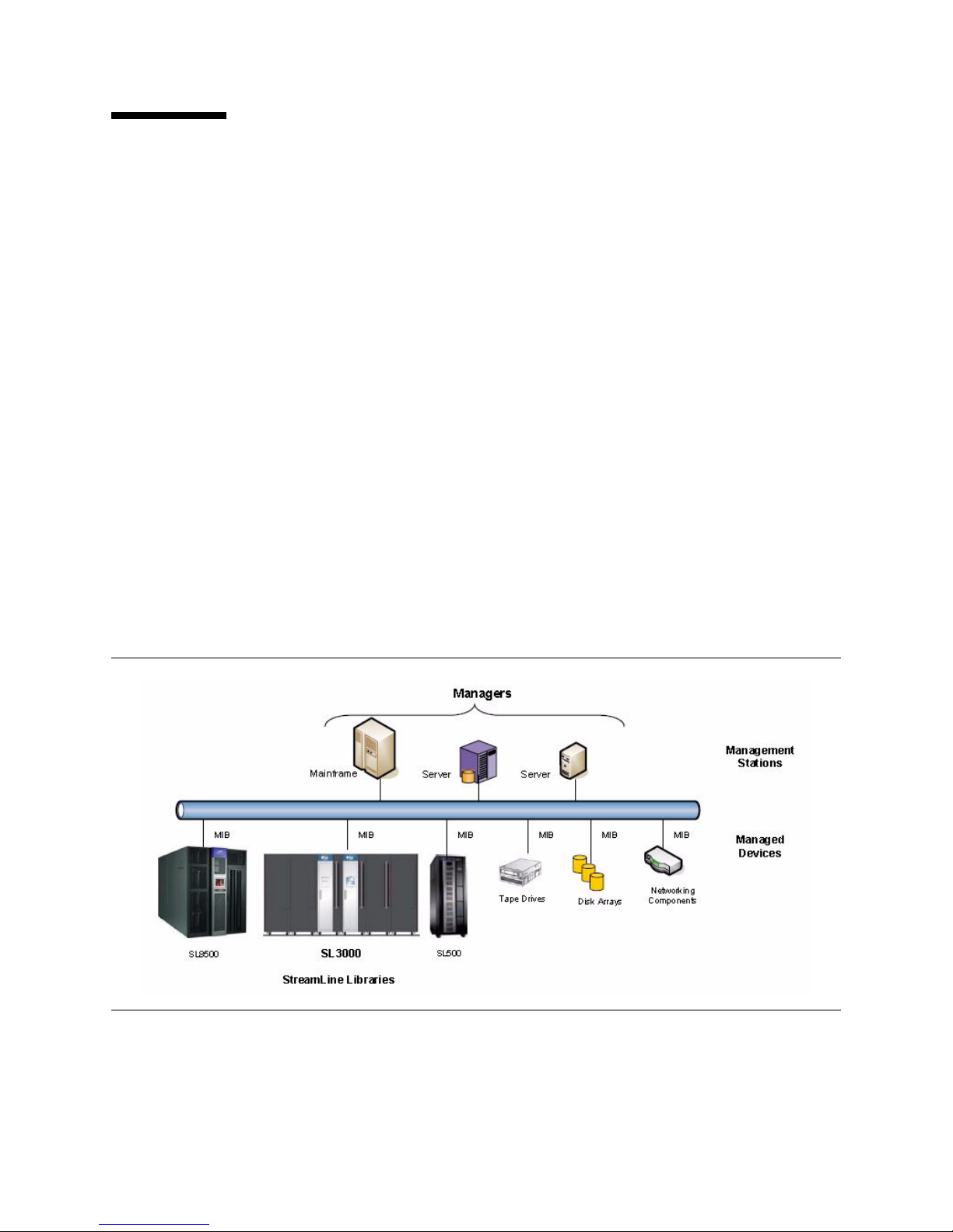
FIGURE 1-16 on page 31 illustrates one example of
Refer to the SL3000 SNMP Reference Guide PN 31619450x for more information.
This reference guide provides information about SNMP and the implementation on
StorageTek SL3000 modular libraries.
316194102 • Revision: B Chapter 1 Introduction 31
Library Management Software
Library Management Software
Library management software applications control the library, manage the volume
database—location and attribute information—plus command activities such as
mounts, dismounts, enters, and ejects.
There are several software components depending on the platform, connection type,
and operating system that support the S
platforms.
L3000 for both mainframe and open system
Note – Th
e same library management software the customer currently has and is
familiar with can probably be upgraded to support the SL3000 library.
TABLE 1-9 lists the compatibility matrix for library management software.
TABLE
1-9 Library Software Compatibility Matrix
Product Required Version1 (or higher)
ACSLS
7.3 (Put0801 for AEM Support)
8.0 (supports ejects of less than 4
2 cartridges at one time)
ExHPDM 6.1 or 6.2
ExLM 6.0 or 6.2
ExPR 6.1 or 6.2
NCS
■ SMC
■ HSC (MVS and VM)
■ Lib Station
■ VTCS
VSM
■ VSM4e
■ VSM4
■ VSM5
6.1 or 6.2
Check for the latest PTF availability
6.1 or 6.2 (includes VTCS and VTSS)
and compatibility.
VTL
■ VTL Plus
■ VTL-V
■ VTL-E
ELS* 7.0
* ELS = Enterprise Library Software—replacement for the NearLine Control Solution (NCS)
1
Make sure the latest PTFs and PUTs are installed.
32 SL3000: Systems Assurance Guide • May 2010 Revision: B • 316194102
1.0 or 2.0

Library Management Software
Nearline Control Solution
StorageTek Nearline Control Solution (NCS) software provides library management
and connectivity with mainframe products such as MVS and VM.
This includes the following software applications (and mor
■ Storage Management Component (SMC)
■ Host Software Component (HSC)
■ Virtual Storage Manager (VSM)
Storage Management Component
Storage Management Component (SMC) is the interface between mainframe operating
systems and the StorageTek automated library control systems, such as HSC and
MVS/CSC. SMC’s primary functions are:
■ Influencing tape allocation according to hardware requirements and customer
policies to ensure that appropriate tape drives are selected.
■ Intercepting tape management, and operating system mount, dismount, and swap
messages and translating them in order to request the required tape hardware
functions from the appropriate NCS automated library control system.
■ Coordinating requests among multiple StorageTek automated libraries.
e not listed):
Note – SMC must r
eside on every MVS host that accesses the SL3000 library plus real
and virtual tape hardware. SMC may communicate with multiple automated libraries,
using cross address space facilities to communicate with applications running on the
same host, and TCP/IP to communicate with HSC systems executing on other hosts.
Host Software Component
The library incorporates the Host Software Component (HSC) to accomplish
automated mounting and dismounting of cartridges for library-attached tape drives.
HSC may be started on several partitions on the same or different mainframes where
all copies work together to fulfill the library control requirements of partitions with
connected instances of SMC.
When an SL3000 library is in a configuration with
version of the StorageTek Host Software Component (HSC) along with the Storage
Management Component to:
■ Influence allocations
■ Intercept mount and dismount messages
■ Receive requests from the interface and translates them into commands
HSC, SL3000 AEM CAP LINKLIBs are:
LINKLIB Updates
SOS610.SPRG1.EVT.I6673474.DR022709.LINKLIB
an MVS host, the host must run a
SOS620.SPRG1.EVT.I6673474.DR022709.LINKLIB
SES700.SPRG1.EVT.I6673474.DR022709.LINKLIB
Note – These LINKLIBs are not replacements for any current LINKLIBs. They need to
be added to the top of the STEPLIB chain in the HSC PROCs.
316194102 • Revision: B Chapter 1 Introduction 33

Library Management Software
Virtual Storage Manager
VSM is a virtual tape system that optimizes the tape storage systems for mainframe
platforms.
VSM-type solutions consist of a server, disk storage, and front-end software, that
complement the physical tape and library products.
The server, disk, and software provide a buffer or cache between the operating systems
and the tape drives for storage in a library.
Hardware for a VSM solution consists of: Software for a VSM solution consists of:
Fault tolerant RAID 6+ disk array
Library and/or library storage modules (LSMs)
Real (physical) tape drives (RTDs) in a library
Virtual tape control system (VTCS) software
resides on the host operating system in the
same address space as HSC.
Multi-volume cartridges (MVCs)—physical cartridges HSC 6.1+ minimum
LibraryStation
LibraryStation provides a communications interface between HSC and one or more
open systems clients running on different hosts.
LibraryStation provides an operator command set that allows you to control operation
through the HSC operator console.
Extended High Performance Data Mover
Extended High Performance Data Mover (ExHPDM) is utility software that performs
high-speed backup and restore of data sets by interleaving very large block sizes on
high-speed, high-capacity tape devices.
ExHPDM achieves its speed by treating all data equally regardless of the type. Its only
function is to move data from disk to very fast tape and back again.
ExHPDM’s version of the best method to move data is to enable tape devices to move
data at their maximum available speed by:
■ Using 256 Kilobyte (KB) blocks or chunks of data
■ Interleaving the 256 KB blocks onto single or multiple tape volumes.
The ExHPDM software moves blocks of data in parallel from several concurrently
executing MVS application programs. The data from the application programs is
buffered into 256 KB tape block sizes in the application program’s address space and
the 256 KB blocks are interleaved onto single or multiple tape volumes.
34 SL3000: Systems Assurance Guide • May 2010 Revision: B • 316194102

Library Management Software
Expert Library Manager
Expert Library Manager (ExLM) software manages the contents of library storage
modules (LSMs) and provides virtual tape management functions.
ExLM includes ExLM Explorer, a graphical user interface that you can use to configure
ExLM by creating configuration files instead of parameter files.
ExLM provides the following management services:
■ Maintain sufficient levels of scratch volumes by:
■ Distributing scratch volumes
■ Synchronizing the scratch status with the tape management system (TMS)
■ Ejecting scratch volumes that have been marked defective by the TMS.
■ Requesting additional scratch volumes on the Enter Report.
■ Maintain sufficient levels of free cells by:
■ Ejecting excess scratch volumes and less active data volumes.
■ Distributing free cells across LSMs within an ACS.
■ Maintain sufficient levels of cleaning cartridges.
ExLM runs as a batch job. You specify the job processing options by creating parameter
files with a text editor or by creating configuration files with the ExLM Explorer GUI.
Expert Performance Reporter
Expert Performance Reporter (ExPR) software collects performance data and generates
reports about status and performance. ExPR has both an MVS component and a PC
component.
■ ExPR MVS, which resides on an MVS host system, builds and maintains a database
of historical performance data that it collects from the library, from the MVS
operating system, and optionally from the site’s tape management system.
Tabular performance and exception reports are generated directly from this database
for display in the MVS environment. For ExPR MVS, all processes are controlled by
a batch task interface.
■ ExPR PC, which resides on one or more PCs, is a Windows application that manages
user-customized subsets of the mainframe database on the PC. Data that is
transferred from the mainframe database can be queried and displayed in graphical
or tabular performance, exception, and quick summary reports.
Data can also be ported to a Microsoft Excel-compatible spreadsheet and other
external applications for further processing.
Enterprise Library Software
Enterprise Library Software (ELS) incorporates NCS products, VTCS products, and
provides customers with a single, integrated software suite. This suite is designed to:
■ Provide the ability to enable tape libraries and virtual solutions, as well as
■ Pro-actively monitor and manage this environment on a continuous basis.
ELS 7.0 is the successor to NCS 6.2 and VTCS 6.2 and consolidates HSC, VTCS, ExPR,
ExLM, and ExHPDM. New functions include capacity planning and a management
reporting GUI.
316194102 • Revision: B Chapter 1 Introduction 35
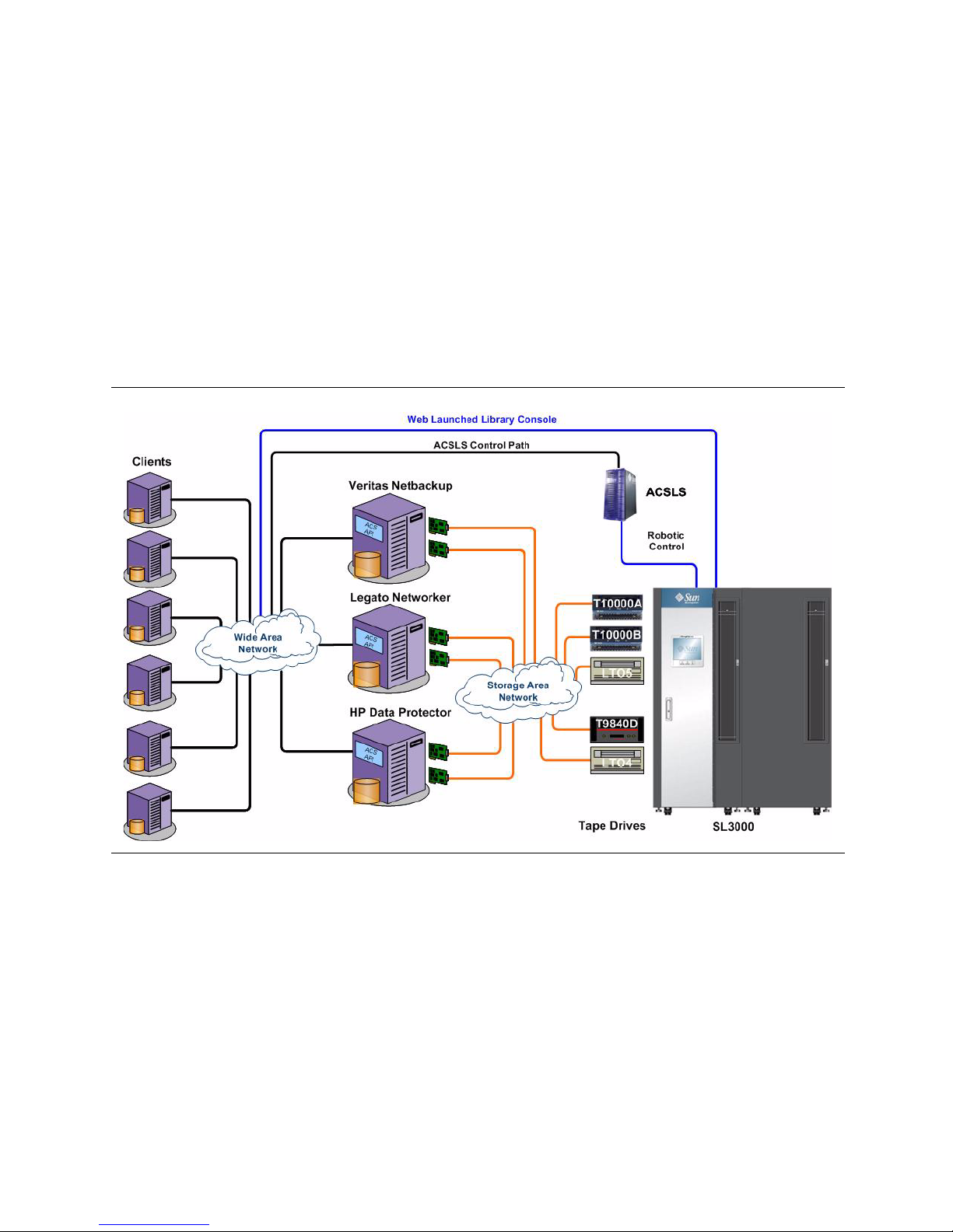
Library Management Software
Automated Cartridge System Library Software
FIGURE 1-17 on page 36 shows an example of an Automated Cartridge System Library
Software (ACSLS) configuration.
ACSLS is an open systems software package that manages library contents and
ontrols library hardware to mount and dismount cartridges on tape drives.
c
This application also provides library manageme
pooling, reports, and library control.
ACSLS Version 7.3 or greater is required for interfacing w
Note – A
FIGURE 1-17 ACSLS Exampl
nt services such as cartridge tracking,
ith the SL3000 library.
CSLS 7.3 requires PUT 0801 for AEM Support.
e
In this example, ACSLS is providing the Library Management Software.
When using ACSLS, this application is sold
36 SL3000: Systems Assurance Guide • May 2010 Revision: B • 316194102
to support a certain number of slots.

Library Management Software
Independent Software Vendors
There are a variety of Independent Software Vendors (ISVs) that have tested their
applications and support connection to the SL3000; for example, some applications
include:
■ BakBone NetVault 7.4+
■ CA ArcServe 11.5+
■ HP Data Protector 5.5/6.0
■ Legato NetWorker 7.3/7.4
■ SAM FS 4.6
■ Tivoli Storage Manager 5.5.1
■ Ve ri ta s Ba ck u pE xe c 11 .0
■ Veritas Netbackup 6.0/6.5
Note – Not every application is l
On different platforms, such as:
■ HP, HP-UX
■ IBM AIX
■ Linux, both Red Hat and Suse
■ Microsoft Windows
■ Solaris
Note – Not every application is tested on eve
isted.
ry platform or platform version.
Check with a Marketing or Sales Representative, Application Vendor, and the
operability Tool at: https://extranet.stortek.com/interop/interop to make sure the
Inter
selected solution (platform, application, tape drives, network, etc.) is supported.
TABLE 1-10 A
Backup Application Solaris IBM AIX HP-UX
CSLS 7.3 Qualification Summary
Microsoft
Windo
ws
Linux
Red Hat SUSE
Legato NetWorker 7.3/7.4 Ye s Yes Ye s Ye s Ye s Yes
Tivoli Storage Manager 5.5.1 Yes Yes Ye s Ye s Ye s Ye s
Symantec Netbackup 6.0/6.5 Ye s Yes Ye s Ye s Ye s TBD
CA ArcServe 11.5+ Yes Yes Ye s Ye s N/A N/A
HP Data Protector 5.5/6.0 Ye s N/A Yes Yes N/A N/A
BakBone NetVault 8.2+ Yes Yes Ye s Ye s Ye s Ye s
SAM-FS 4.6 Ye s N/A N/A N/A N/A N/A
316194102 • Revision: B Chapter 1 Introduction 37

Standards of Conformance
Standards of Conformance
TABLE 1-11 lists the standards to which the SL3000 complies.
TABLE 1-11 Standar
Country Standard
U.S.A. Federal Communications Com
Japan Voluntary Control Council for Inter
European Union
(CE mark)
Australia /
New Zealand
Tai wa n Bureau of Standards, Metrology and Inspection (BSMI) Law,
Canada Canadian EMC Law ICES-003
Korea Korean EMC Law
Emissions European Union Test Requirements
HF Radiated EN55022 Class A
HF Conducted EN55022 Class A
Harmonic Current EN61000-3-2
Voltage Fluctuations
Flicker
and
d of Compliance
mission (FCC). Title 47, Part 15, Subpart B,
and as an Unintentional Radiators Class A
ference (VCCI), Class A (CISPR22)
Electromagnetic Compatibil
(including EN55022, EN55024, EN61000-3-2, EN61000-3-3 and amendments)
EMC Framework AS/NZS 3548
Taiwan CNS13438
EN61000-3-3
ity Directive 89/336/EEC and 2004/108/EC
Directive Description
RoHS Reduction of Hazardous Substances
WEEE Waste Electrical and Electronic Equipment (e-waste)
Standard Description
EDS 3-3 AC Powerline
EDS 5-6 Product Safety Requirements
EDS 6-3 Electrostatic Discharge (ESD) Immunity
CP-7-1-2 Product Safety
38 SL3000: Systems Assurance Guide • May 2010 Revision: B • 316194102

CHAPTER
2
Systems Assurance
This chapter contains information about the systems assurance process.
The system assurance process is the exchange of information among team members to
ensure that no aspects of the sale, order, installation, and implementation are
overlooked. This process promotes an error-free installation and contributes to the
overall customer satisfaction.
Systems assurance team members—the customer and StorageTek—ensure that all
aspects of the process are planned carefully and performed efficiently.
System Assurance Planning Meetings
The purpose of the system assurance planning meetings are to:
■ Introduce the customer to the SL3000 modular library
■ Explain the system assurance process and establish the team
■ Prepare for the installation and implementation
■ Schedule and track the entire process
TABLE 2-1 on page 40 provides a list of tasks to start with.
Make any adjustments or add more tasks as the team needs to ensure a quality process.
316194102 • Revision: B 39

System Assurance Planning Meetings
TABLE 2-1 System Assurance Checklist
Task Completed?
Introduce the team members to the customer.
Complete the Team Member Contact sheets.
Make additional copies as necessary.
Describe the SL3000 modular library, options, and features for the customer.
See Chapter 1, “Introduction” for information and topics.
Identify and define the customer’s requirements.
Comments:
Understand the customer’s expectations.
Comments:
Review the information in Chapter 3, “Site Planning”
Comments:
Yes ❏ No ❏
Yes ❏ No ❏
Yes ❏ No ❏
Yes ❏ No ❏
Yes ❏ No ❏
Review and complete the surveys in Chapter 4, “Customer Site Survey”
Comments:
Identify any additional items the customer might need.
■ Library management software and additional hardware activation keys
■ Media—data and cleaning cartridges, labels, media services
■ Tape drives, drive tray conversions, encryption
■ Cables and network components
■ Service delivery platform (SDP)
Review the Order Work Sheets in Chapter 5, “Ordering”.
Comments:
Determine the installation schedule:
Equipment arrival date:
Installation date:
Yes ❏ No ❏
Yes ❏ No ❏
Yes ❏ No ❏
Yes ❏ No ❏
40 SL3000: Systems Assurance Guide • May 2010 Revision: B • 316194102

Customer Contact Sheet
Name:
Title:
Telephone Number:
FAX Number:
Cell Phone / Pager:
E-mail Address:
Name:
Title:
Telephone Number:
FAX Number:
Customer Contact Sheet
Cell Phone / Pager:
E-mail Address:
Name:
Title:
Telephone Number:
FAX Number:
Cell Phone / Pager:
E-mail Address:
Name:
Title:
Telephone Number:
FAX Number:
Cell Phone / Pager:
E-mail Address:
Note – Customer team members may include: IT professionals, systems and network
administrators, finance, security, and facility planners.
316194102 • Revision: B Chapter 2 Systems Assurance 41

StorageTek Member Contact Sheet
StorageTek Member Contact Sheet
Name:
Title:
Telephone Number:
FAX Number:
Cell Phone / Pager:
E-mail Address:
Name:
Title:
Telephone Number:
FAX Number:
Cell Phone / Pager:
E-mail Address:
Name:
Title:
Telephone Number:
FAX Number:
Cell Phone / Pager:
E-mail Address:
Name:
Title:
Telephone Number:
FAX Number:
Cell Phone / Pager:
E-mail Address:
Note – StorageTek Representatives may include: marketing, sales, and account
representatives, systems engineers (SEs), Professional Services (PS), installation
coordinators, and trained services personnel.
42 SL3000: Systems Assurance Guide • May 2010 Revision: B • 316194102

CHAPTER
3
Site Planning
FIGURE 3-1 SL3000 Library—Front Door Open
This chapter consists of the following topics to assist in planning an installation.
■ Specifications:
■ “Metric Dimensions (frame measurements)” on page 44
■ “Standard Dimensions (frame measurements)” on page 45
■ “Service Clearances” on page 48
■ “Floor Loading” on page 50
■ “Fire Suppression Planning” on page 51
■ “Environmental Requirements” on page 52
■ “Power Consumption” on page 54
■ “Installation Considerations” on page 56
■ “Installation Time and Personnel” on page 56
■ “Customer ’s Floor” on page 59
■ “Cable Routing” on page 60
■ “Seismic or Earthquake Ratings” on page 61
■ “Obtaining a Password” on page 67
■ “Installing the Library Console Software” on page 68
■ “SL3000 Configuration Work Sheet” on page 69
316194102 • Revision: B 43

Specifications
Specifications
FIGURE 3-2 Metric Dimensions (frame measurements)
44 SL3000: Systems Assurance Guide • May 2010 Revision: B • 316194102

FIGURE 3-3 Standard Dimensions (frame measurements)
Specifications
For individual specifications see:
■ “Base Module” on page 46 ■ “Service Clearances” on page 48
■ “Drive Expansion Module” on page 46 ■ “Floor Loading” on page 50
■ “Cartridge and Parking Expansion Modules” on page 47 ■ “Fire Suppression Planning” on page 51
■ “Access Expansion Module” on page 47 ■ “Pallets” on page 57
■ “Covers, Doors, and Service Clearances” on page 47 ■ “Customer’s Floor” on page 59
316194102 • Revision: B Chapter 3 Site Planning 45
Specifications
Base Module
TABLE 3-1 Base Module Specifications
Dimension Measurement
Height 196.7 cm (77.45 in.) on casters, to
200.15 cm (78.8 in.), fully adjusted [adjustment = 3.43 cm (1.35 in.)]
Width 76.8 cm (30.23 in.) without covers*
81.3 cm (32 in.) without side covers
91.6 cm (36.03 in.) with end covers*
Depth (doors closed)
Depth (with service access)
Wei gh t
121.8 cm (47.95 in.)
248.8 cm (97.95 in.)
■ Frame only = 361 kg (796 lb)
■ Shipping weight = 411 kg (905 lb)
■ Installed, with:
■ 8 drives and media = 623 kg (1372 lb)
■ 16 drives and media = 661 kg (1457 lb)
■ 24 drives and media = 687 kg (1514 lb)
Side cover (end cap) 7.4 cm (2.9 in.) width and 18.5 kg (41 lb) per side
*Side Covers: Are shipped with the base module. As you add more modules, the side covers are removed from
this module and installed on the new module (either left, right, or both).
Drive Expansion Module
TABLE 3-2 Drive Expansion Module Specifications
Dimension Measurement
Height Same as base module
Width (module only) 76.8 cm (30.23 in.) without covers
158.1 cm (62.26 in.) without covers
168.3 cm (66.26 in.) with Base Module and end covers
Depth (doors closed)
Depth (with service access)
Wei gh t
46 SL3000: Systems Assurance Guide • May 2010 Revision: B • 316194102
121.8 cm (47.95 in.)
248.8 cm (97.95 in.)
■ Frame only, no CAP = 265 kg (584 lb)
■ Shipping (frame only, no CAP) 314 kg (693 lb)
■ Shipping (frame plus CAP) = 321 kg (708 lb)
■ Installed with:
■ 8 drives and media, no CAP = 540 kg (1190 lb)
■ 16 drives and media, no CAP = 596 kg (1314 lb)
■ 24 drives and media, no CAP = 647 kg (1426 lb)
■ 32 drives and media, no CAP = 709 kg (1564 lb)
■ 8 drives and media, with CAP = 582 kg (1284 lb)
■ 16 drives and media, with CAP = 621 kg (1369 lb)
■ 24 drives and media, with CAP = 660 kg (1456 lb)
■ 32 drives and media, with CAP = 723 kg (1594 lb)
Cartridge and Parking Expansion Modules
TABLE 3-3 Cartridge and Parking Expansion Module Specifications
Measurements
Specifications
Dimension
CEM PEM
Height Same as base module
Width 76.8 cm (30.22 in.) module only
168.28 cm (66.25 in.) with Base Module and side covers
Depth 77.5 cm (30.5 in.) frame only
Wei gh t
■ Frame only 175 kg (385 lb)
■ Shipping = 213 kg (469 lb)
■ Installed, with media = 340 kg (749 lb)
Access Expansion Module
TABLE 3-4 Access Expansion Module Specifications
Dimension Measurement
Height Same as base module
Width 91.5 cm (36.0 in.) without covers
98.8 cm (38.9 in.) with one side cover
Depth 77.5 cm (30.5 in.)
Weight 204.2 kg (450 lb)
■ Frame only = 122.5 kg (270 lb)
■ Shipping = 213 kg (469 lb)
Covers, Doors, and Service Clearances
TABLE 3-5 Covers, Doors, and Service Clearance Specifications
Dimension Measurement
Height 190 cm (77.45 in.) frame on casters Adjustable by 3.5 cm (1.35 in.)
Door thickness Front: 1.9 cm (0.75 in.)
Rear: 4.5 cm (1.75 in.)
Door latches 2.53 cm (0.9 in.)
Important: The latch adds another 2.5 cm (1 in.) depending on the
module location and measurement use.
Service clearance
Front without AEM:
Front with AEM:
Rear:
Both doors open
Tot al :
Side cover (end cap) 7.4 cm (2.9 in.) width and 18.5 kg (41 lb) per side
*Side Covers: Are shipped with the Base Module. As you add more modules, the side covers are removed from
the Base Module and installed on the new module (either left, right, or both).
316194102 • Revision: B Chapter 3 Site Planning 47
46 cm (18 in.)
61 cm (24 in.)
81 cm (32 in.)
264 cm (104 in.)
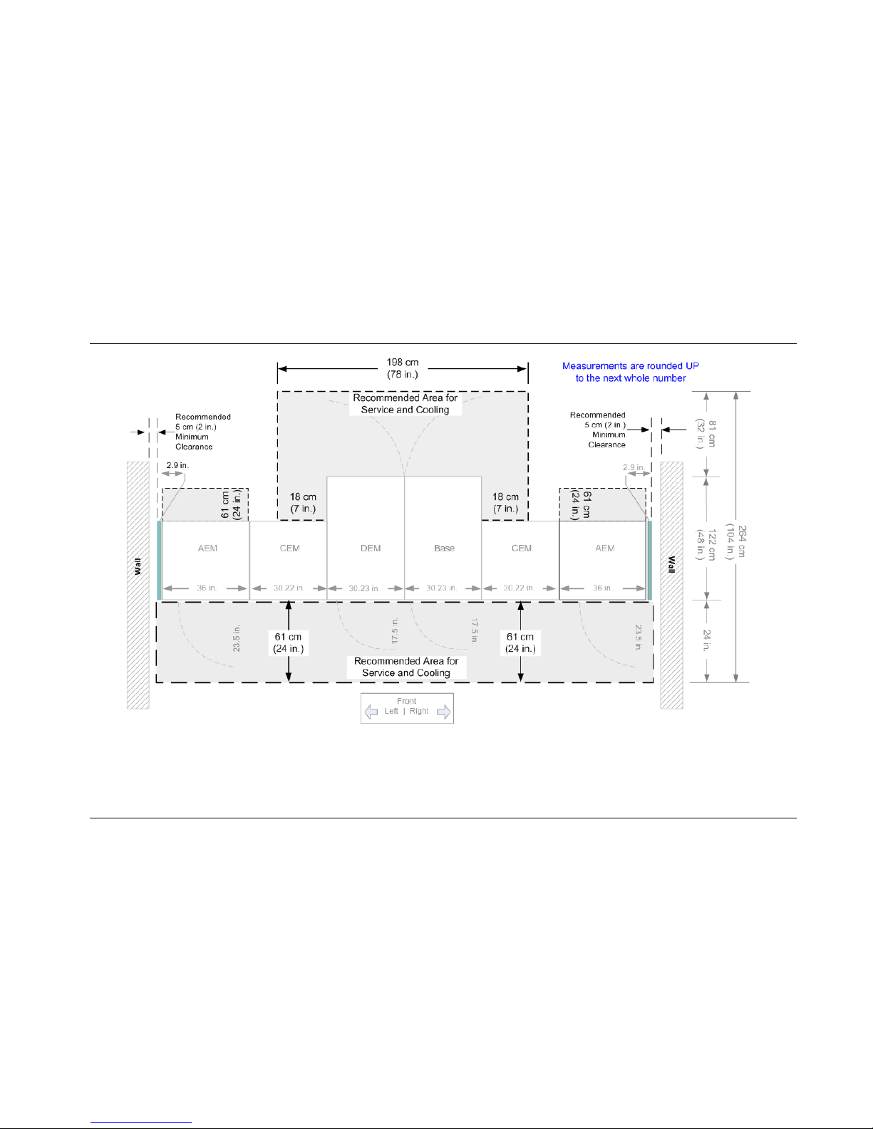
Specifications
48 SL3000: Systems Assurance Guide • May 2010 Revision: B • 316194102
Service Clearances
FIGURE 3-4 Service Clearances—Minimum and Recommended
Clearance:
Front—Use, Front door opening, CAP processing
Rear—Service, tape
drives, cabling
Sides—Cooling
Overall width
Overall length—(
Variable)
Minimum Measurements:
44.5 cm (17.51 in.), AEM 60 cm (23.5 in.)
80.3 cm (31.62 in.)
5 cm (2 in.)
122 cm (48 in.)
Variable by number of modules
From: 91.5 cm (36 in.) To: 965.2 cm (380 in.)
Recommended Clearances:
Front: 61
cm (24 in.)
Rear: 81
cm (32 in.)
Side: 5 cm (2 in.) min
imum
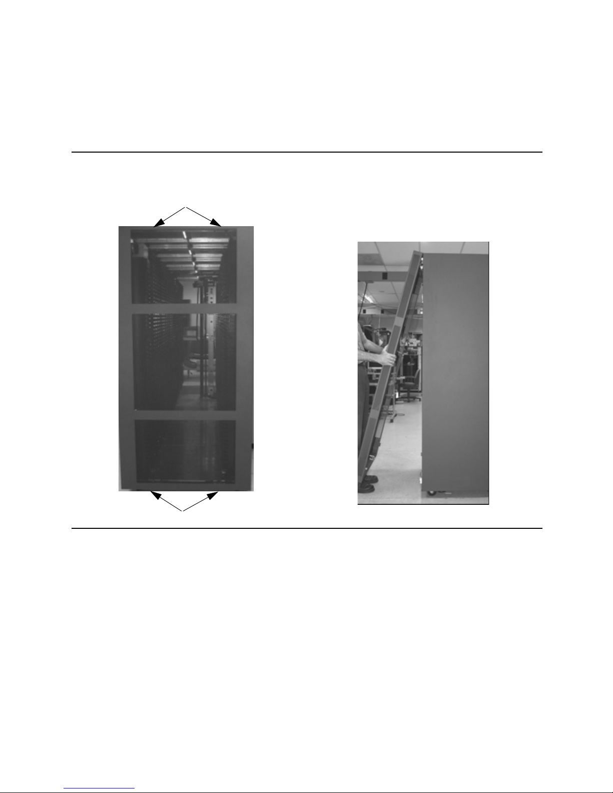
Specifications
Clamps
Clamps
Side Clearance During Installation
The SL3000 requires only a 5 cm (2 in.) clearance on the sides of the library; however,
during the initial installation, 46 cm (18 in.) is required to install the end (side) covers.
FIGURE 3-5 End Cove
r Clearance
To tighten or loosen the end covers requires a
5/16-inch hex key wr
ench.
■ To remove the end covers:
Swing the bottom of the end cover away
the library approximately 46 cm (18 in.).
■ To install:
Place the cover on the brackets and swing it
into place.
from
316194102 • Revision: B Chapter 3 Site Planning 49

Specifications
50 SL3000: Systems Assurance Guide • May 2010 Revision: B • 316194102
Floor Loading
FIGURE 3-6 Floor Loading—Load Pads
The customer’s floor must be capable of supporting 454 kg (1000 lb) per weight distribution pad.
This weight represents the modules, with components,
and cartridges.
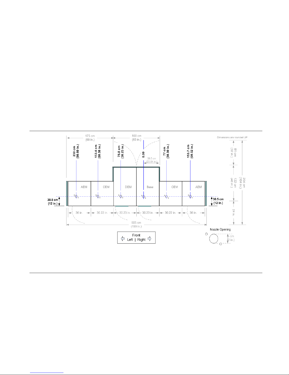
316194102 • Revision: B Chapter 3 Site Planning 51
Specifications
Fire Suppression Planning
FIGURE 3-7 shows the accesses for fire suppression planning. The library does not ship with a fire suppression system,
although features have been incorporated into the library to allow for one. Professional Services offers systems which can be
installed on site.
FIGURE 3-7 Fire Suppression Ceiling Access (Viewed from the top of the library)
Details:
■ Openings = One per module that measure 5 cm (2 in.) diameter Note: Do not cut/alter the provided opening without contacting Professional Services.
■ Plates = Cover the openings and measure 7 cm (2.75 in.) square and 1 cm (0.48 in.) thick.
■ These plates are what contractors can use to drill in to for a custom fit of the nozzles.
■ Screws = Two T25 Torx screws
■ Nozzle protrusion into the library to clear robotic operation = 1 cm (0.4 in.) from the top of the library
Environmental Requirements
Environmental Requirements
Although the SL3000 library will function over a full list of environmental ranges as
specified below, optimal reliability is achieved if the environment is maintained between
the recommended ranges.
TABLE 3-6 Envir
Description Optimum Recommended Range Full Operating Range
Temperature
onmental Specifications
Operating
Non-operating
Relative Humidity
Operating
Non-operating
Wet bulb (operating) 25.6°C (78°F) maximum, non-condensing
Heat Output See “Power Consumption” on page 54 and
Power Consumption
**Maximum loading includes 56 tape drives, 2 TallBots, and up to 10 CAPs.
Important:
Although this equipment is de
20% to 80% humidity, industry best practices recommends computer rooms maintain
a relative humidity of 40% to 50% for best performance.
TABLE 3-7 Environmental Definitions
British thermal units (Btu) A measure of the amount of heat required to raise the temperature of
22°C (72°F) 20° – 25°C (68° – 77°F) +16° to 32°C (60° to +90°F)
+4° to +32°C (+40° to +90°F)
45% 40% – 50% 20% to 80% (non-condensing)
20% to 80% (non-condensing)
“Calculating Power Consumption” on page 55 for details
signed to operate in environmental conditions of
one pound of water one degree Fahrenheit.
British thermal units are most commonly associated with power over a
unit of time—Btu per hour (Btu/hr).
Relative Humidity A measure of water vapor in the air.
Temperature The measurement of hot and cold to specific scales, such as Celsius
Watt A watt is a unit of power or the amount of energy per unit of time.
Wet bulb The difference in temperature between wet bulb (humidity) and dry
52 SL3000: Systems Assurance Guide • May 2010 Revision: B • 316194102
(also called centigrade) and Fahrenheit.
The Celsius temperature scale uses 0° for the freezing point of water and
100° for the boiling point of water. The Fahrenheit temperature scale
uses 32° for the freezing point and 212° for the boiling point.
Often the term watt is used for expressing energy consumption as
kW (kilo-Watts).
bulb (temperature) provides a measure of atmospheric humidity.

Environmental Requirements
Airborne Contaminants
Control over contaminant levels in a computer room is an extremely important
consideration when evaluating an environment. The impact of contamination on
sensitive electronic hardware is well recognized, but the most harmful contaminants
are often overlooked because they are so small.
Library rail components, tape drives, and media are subject to damage from airborne
particulates (0.3 micr
adhere to the requirements of:
■ A Class 100,000 Clean Room
■ ISO 14644-1 Class 8 or 9 environment
ons and smaller). The operating environment should strive to
For more information refer to the Data Center Site Plannin
g Guide at:
http://dlc.sun.com/pdf/805-5863-13/805-5863-13.pdf
For example:
Excessive concentrations of certain gasses can accelerate co
electronic components. Gaseous contaminants are a particular concern in a computer
room because of the sensitivity of the hardware.
TABLE 3-8 lists some recommendations
TABLE 3-8 Gas L
Chemical Name Formula ASHRAE OSHA (PEL) ACGIH NIOSH
Acetic Acid CH3COOH Not defined 10 ppm Not defined Not defined
Ammonia NH 3500 µg/m3 350 ppm 25 ppm Not defined
Chlorine Cl 2100 µg/m
Hydrogen Chloride HCl Not defined 5 ppm (c) Not defined Not defined
Hydrogen Sulfide H2S 50 µg/m3 320 ppm (c) 10 ppm 10 ppm
Ozone O3 235 µg/m3 30.1 ppm Not defined Not defined
Petrol-hydrocarbons C
Sulfur Dioxide SO
Sulfuric Acid H2SO4 Not defined 1 ppm Not defined 1 ppm (c)
imit Recommendations
Not defined 500 ppm 75 ppm 300 ppm
n Hn
80 µg/m3 35 ppm 2 ppm 0.5 ppm (c)
2
for gaseous limits.
3
31 ppm (c) Not defined 0.5 ppm (c)
rrosion and cause failure in
PEL: Permissible Exposure Limit
ppm: Parts Per Million
3
: Micrograms Per Cubic Meter
µg/m
(c): ceiling
316194102 • Revision: B Chapter 3 Site Planning 53

Power Consumption
54 SL3000: Systems Assurance Guide • May 2010 Revision: B • 316194102
Power Consumption
TAB LE 3-9 provides the power consumption (Watts), CO2 emission values, and Btu/hr for the SL3000 library.
TABLE 3-9 Power Consumption Quick Reference
Component
Qty
Idle Maximum Continuous
Watts
C02
Emissions
1
Btu/hr Watts
C02
Emissions
1
Btu/hr
Base Library
2
(required)
Includes one ECM
3
, one robot4, and one CAP
1 179 3.668963 611.106 239 4.9 816
Internal Ethernet Switch (required) each 40 0.82 136.56 40 0.82 136.56
Additional robot (optional)
4
1 28 0.573916 95.592 55 1.1 188
Operator Panel (optional)
5
1 29 0.594413 99.006 37 0.8 126
Additional CAP (optional)
6
each 10 0.20497 34.14 14 0.3 47.8
Tape Drive and Tray Assembly
7
T9840C each 91.6 1.8775252 312.7224 122.6 2.5 419
T10000 each 73 1.496281 249.222 115.2 2.4 393
LTO each 37 0.758389 126.318 56.9 1.2 194
Access Expansion Module (optional, 1 or 2) each 8 0.163976 27.312 30 0.6 102
Notes:
1. CO2 Emissions is kg of C02 per day, which is equal to 0.020497 Watts.
2. Drive Expansion Module; use the individual components (CAPs, Ethernet switches, and tape drives). Cartridge Expansion Module; none required.
3. Electronic Control Module includes one HBCR and one HBT cards, two cooling fans. [Watts = 141 (idle) 170 (max.); CO2 = 2.89 (idle) 3.48 (max)]
4. One SL3000 can support up to two robots
5. One SL3000 can support one Operator Panel
6. One SL3000 can support up to ten CAPs
7. Drive Tray includes HBD card, drive DC to DC power supply, fans-if applicable, and the drive itself. The SL3000 supports up to 56 drives total.
Calculating Power Consumption
To calculate Power and CO2 emissions:
■ Use [kg of C02 per day] equals *.020497 [watts].
■ Use the constant that is applicable for your country.
Power Consumption
To convert electrical values to British Thermal Units (Btu
/hr), multiply the number of
Watts by 3.412 or 1 kW = 3.412 Btus.
3.41214 x Watts = Btu/hr
Many manufacturers publish kW, kVA, and Btus for their equipment. Often, dividing
the Btu value by 3412 does not always equal the published kW value.
■ Where the information is provided by the manufacturer, use it.
■ Where it is not, use the formula.
To calculate Btus:
■ Add up all the applicable Wattage values for the configuration.
■ Multiply the total Watts sum by 3.412.
■ This equals the number of Btu/hr.
For example:
Using the maximum continuous values for the following components
Qty Component Watts
1 SL3000 Base module (including one ECM, one Robot, one CAP) 239
1 Internal Ethernet switch 40
16 LTO driv e s 910.4
Tot al : 1189.4
Multiply that by 3.412, which equals 4058.2 Btu/hr maximum
continuous operation.
Another example:
Qty Component Watts
1 SL3000 Base module (including one ECM, one Robot, one CAP) 239
1 Internal Ethernet switches 40
8 T9840 drives 732.8
1 Drive Expansion Module —
1 Internal Ethernet switch 40
8 T10000 drives 584
4 Cartridge Expansion Modules —
3 Optional CAPs (3 x 10 Watts) 30
Tot al : 1665.8
Multiply that by 3.412, which equals 5683.7 Btu/hr maximum
316194102 • Revision: B Chapter 3 Site Planning 55
continuous operation.

Installation Considerations
Installation Considerations
The SL3000 library has several installation requirements that must be considered. The
following sections outline some basic considerations that must be made when planning
for an installation.
Available Space
You and your customer must determine:
■ The number and types of modules to be installed.
■ Are there additional modules in the future? If so, allow space for this growth.
■ The amount of space required to install the equipment.
A suggested working area (not including the space required for the pallets) is
approxima
Installation Time and Personnel
tely 19 m
2
(200 ft2).
TABLE 3-10 shows the estimated times for the installation of modules and components.
At least two qualified service representatives should install the library.
These times do
TABLE 3-10 Installation T
Module/Component
Base Module with 8 drives (standard) 3 hours 2 6 hours
Base Module and Drive E
Base Module and Cartridge Expansion Module 4 hours 2 8 hours
Each additional Cartridge Expansion Module 2 hours 2 4 hours
Two Parking Expansion Modules 2 hours 2 4 hours
Access Expansion Modules (each) 2 hours 2 4 hours
CAPs 1 hour 2 2 hours
Tape Drive (each drive) 0.5 hours 1 0.5 hours
Operator Panel or Window 0.75 hours 1 0.75 hours
Firmware 0.2 hours 1 0.2 hours
Integration (cables, hubs, s
not include library initialization, testing, audits, and feature upgrades.
ime Estimates
Time
Estimate
xpansion Module 5 hours 2 10 hours
witches, connections) 8 hours 1 8 hours
Personnel
Required
Total Perso n
s
Hour
Media install (each) 0.02 hours 1 variable
To achieve the estimated installation time a
tasks can be performed simultaneously. For example, while one person is installing a
CAP, the other person could be installing tape drives.
56 SL3000: Systems Assurance Guide • May 2010 Revision: B • 316194102
nd make the best use of personnel, some

Installation Considerations
Pallets
The SL3000 library modules and other components are shipped on pallets.
Note – I
capable of safely handling the weight.
FIGURE 3-8 lists each module and its shipping specifications.
FIGURE 3-8 Pallet and
f palletized equipment must be transported on elevators, the cars must be
Module Shipping Information
Module Height Width Depth Weight
Base Drive 216 cm (85 in.) 97 cm (38.3 in.) 134 cm (53 in.) 410 kg (905 lb)
Drive Expansion 216 cm (85 in.) 97 cm (38.3 in.) 134 cm (53 in.) 321 kg (708 lb)
Cartridge Expansion 216 cm (85 in.) 97 cm (38.3 in.) 96 cm (38 in.) 213 kg (469 lb)
Parking Expansion 216 cm (85 in.) 97 cm (38.3 in.) 96 cm (38 in.) 213 kg (469 lb)
Access Expansion 216 cm (85 in.) 97 cm (38.3 in.) 148 cm (58 in.) 260 kg (570 lb)
Important: Possible Physical Injury.
Either a split-pallet or pallet-ramp d
the module at the customer site. SL3000 library modules are shipped with wheels
(casters) already attached to allow for easy positioning within the data center. Once
positioned, the modules must be raised from their wheel-base to rest upon load plates
for stability and/or leveling purposes.
The suggested library adjustment height is 200 cm (77.6 in.). Therefore, make sure that
the top of the library does not interfere with cei
316194102 • Revision: B Chapter 3 Site Planning 57
esign is used to ship and provide safe removal of
ling fixtures in the data center.

Installation Considerations
Pallet Double Stacking
Important: Possible Physical Injury.
Many SL3000 modules are being deliver
the shipping companies due to the narrow pallet design.
ed stacked, unsecured, on a second pallet by
Field personnel are trying to remove the modules by tilting and s
liding the palleted
module off the second pallet underneath.
Do not attempt to remove an SL3000 module fr
om a second pallet without the proper
equipment. The safe removal of a library module from the second pallet requires a
forklift operated by a qualified operator. Under no circumstances are StorageTek
employees to attempt removal of the stacked module from the second pallet.
In the event that a safe method of removal cannot be accomplis
hed after delivery at the
customer site, please notify your install coordinator. Inform them that the library may
need to be picked up from the site by the delivery company, taken off the second
pallet, and re-delivered.
Delivery personnel are not authorized to remo
ve the modules from the second pallet
without the proper equipment.
FIGURE 3-9 Do Not Stack
on Second Pallet
58 SL3000: Systems Assurance Guide • May 2010 Revision: B • 316194102

Installation Considerations
Customer’s Floor
The library can be installed on a raised, solid, or carpeted floor and have a smooth
surface.
■ If raised, there should not be ventilation panels directly below the library.
■ If solid, to avoid tripping, route cables from the ceiling.
■ If carpeted, make sure the carpet is approved for computer-room equipment and
provides protection from electrostatic discharge (ESD).
The load-bearing capacity of the customer ’s floor is another consideration.
■ A single Base module, when fully populated, weighs:
■ From 623 kg (1372 lb) with 8 drives and media
■ To 687 kg (1514 lb) with 24 drives and media
■ An additional drive expansion module, when fully populated, weighs:
■ From 482 kg (1290 lb) with 8 tape drives
■ To 723 kg (1594 lb) with 32 tape drives
FIGURE 3-10 Fl
Additionally, since modules are joined together and
the TallBots travel along a rail, each
module must be adjusted so that TallBots travel along a level plane.
Some customer floors may contain
slight slopes in them, so these variations must be
taken into account. Any excessive out-of-plane conditions could cause binding,
premature wear, and damage to the TallBots.
FIGURE 3-10 shows an example of this; a
llowing for a slope of 3.4 cm (1.35 in.).
oor Slope
Height adjustment 197 cm (77.45 in.) on casters, to
200 cm (78.95 in.), fully adjusted
Caster height:
Adjustment range:
316194102 • Revision: B Chapter 3 Site Planning 59
6.6 cm (2.59 in.) minimum adjustment
0 – 3.5 cm (0 – 1.35 in.)
To:
10 cm (3.94 in.) maximum adjustment

Installation Considerations
Cable Routing
The SL3000 library has rear door cut-outs on both the top and bottom of the door to
allow for cable routing. This is a 5 cm (2 in.) opening the runs 73 cm (29 in.) along the
length of the door with cable routing hardware and reliefs available.
FIGURE 3-11 shows a Base Module rear door with standard 61 cm (24 in.) square floor
tiles visible through the door perforations as a comparison. Because of the openings in
the rear door, several different floor (or ceiling) cut-outs will work to route cables.
When planning to route cables, make sure to include locations for power, drive
interface, library control, and Ethernet cables. As a best practices, when possible, route
power cables through one cut-out and signal cables through another cut-out.
FIGURE 3-11 Cable Routing
60 SL3000: Systems Assurance Guide • May 2010 Revision: B • 316194102

Installation Considerations
Seismic Mounting
Casters
Leveling Pads
Seismic or Earthquake Ratings
The requirements for seismic compatibility vary dramatically throughout the world.
As such, StorageTek does not offer a standar
■ It is recommended that any customer who has seismic concerns work with local
experts who are familiar with the local code and requirements.
■ Professional Services can also be engaged to help coordinate this activity.
Caution – Bodily injury and equipment damage: A qualified seismic engineer must be
consulted to verify seismic zone exposures and adequate site preparation.
For sites in areas of seismic activity, the customer may wish to permanently fix the
library position for added stability. The SL3000 library provides mounting holes in the
floor of each module where half-inch carriage bolts (mounting studs) can be used to
permanently fix the library’s position.
d “seismic” feature for the SL3000.
FIGURE 3-12 shows the locations of the casters, leveling pad
FIGURE 3-12 Seismic Mo
Base and DEM Details
s, and the mounting holes.
unting Locations
316194102 • Revision: B Chapter 3 Site Planning 61

Installation Considerations
Seismic Mounting
Casters
Leveling Pads
FIGURE 3-12 Seismic Mounting Locations (Continued)
CEM Details
62 SL3000: Systems Assurance Guide • May 2010 Revision: B • 316194102
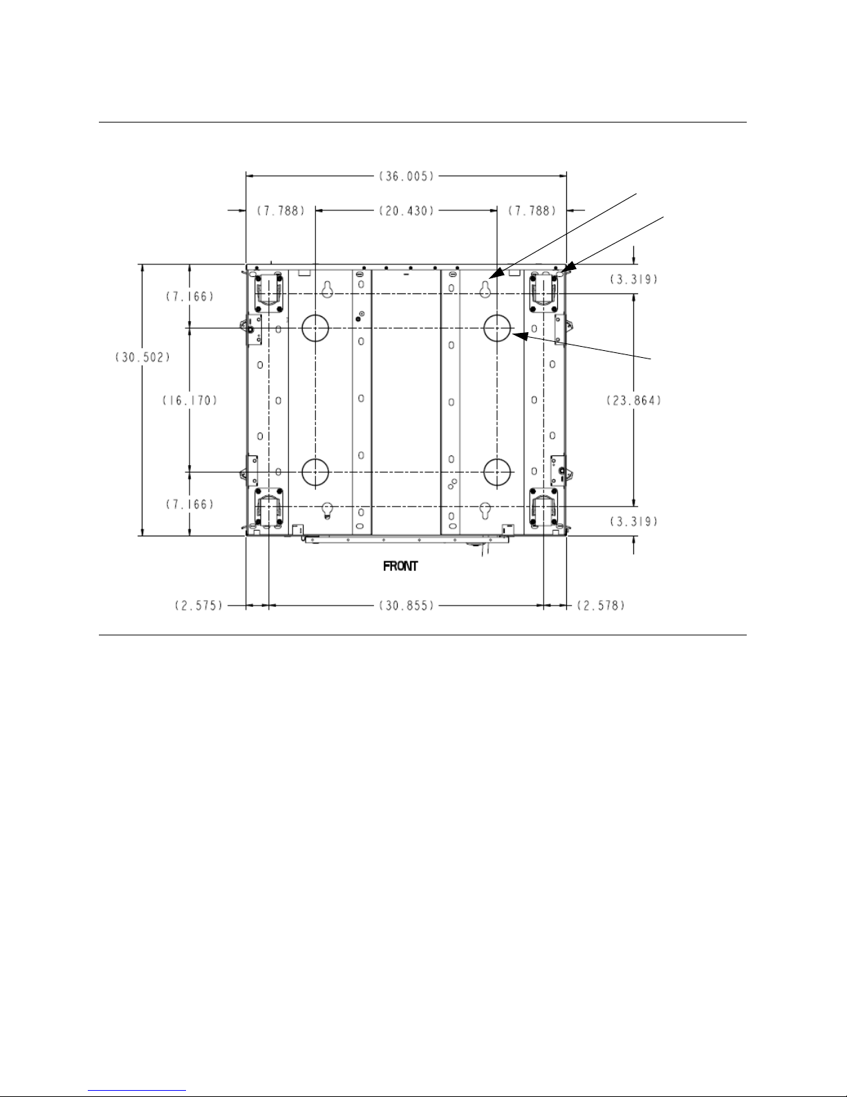
FIGURE 3-12 Seismic Mounting Locations (Continued)
Seismic Mounting
Casters
Leveling Pads
AEM Details
Installation Considerations
316194102 • Revision: B Chapter 3 Site Planning 63

Installation Considerations
Installation Tools—Required
TABLE 3-11 lists the installation tools required for the SL3000. There is no special
district installation toolkit required.
Note – If you alr
eady have SL8500 libraries in your area, the extractor, hex wrench and
rack alignment tool can also be used for the SL3000; if these few special tools are not
available, you must order them separately.
A Web site that lists all tools available is located at the following URL:
http://sunsolve.central.sun.com/handbook_internal/FieldTools/
TABLE 3-11 Installation T
Standard Tools Part Number Use
Tool b ag 24100254
Torx screwdriver and
T8, T10, T15, T25 bits
3/8-in. drive ratchet wrench 3010420130 See 5/16-in. attachment
Wire side cutters 24100041 Cutting shipping straps
Adjustable wrench
(must be adjustable to accept
-in. nut)
7/8
Phillips screwdriver
ools
4850
■ T8: Removal and replacement of the PUK card.
■ T10: PUO, PUW, PUN, PUF, PUZ cards.
■ T15: Operator panel, window, blank plate, arrays
■ T25: Removal/replacement of shipping brace, track
adjustment, CAP screws, Ethernet switch
Locking the weight distribution pad’s nut with the height
adj
ustment bolt.
Flat blade screwdriver
Special Tools
5/16-in. hex Allen on
3/8-in. drive
9/16-in. socket on
3010420646 Module height adjustment,
joining modules
Module removal from pallet
3/8-in.-drive
Copper rail connector
extractio
n tool
313921001 Track terminator removal
(supplied with base module installation kit)
Rail separator/joiner 4199410xx Supplied with base module installation kit.
Used for releasing/joining extrusions
Pallet jack Obtain locally Movement of pallets
Serial cable for laptop 24100134 CLI access to library
Crossover cable for laptop 24100163 CLI access to library
Drive tray power-on tool 314831204 See description below.
In addition to these tools, the following items are required:
■ Flashlight
■ Step stool
■ Vo lt / O hm me t er
64 SL3000: Systems Assurance Guide • May 2010 Revision: B • 316194102

Installation Considerations
Dr ive Tray Power-o n Too l
A tool is available to assist you in removing a stuck tape within a library tape drive.
This tool allows you to power-on a drive
outside the library for the primary function of
removing a cartridge stuck within a library drive.
The kit part number is 314831204; which contains the instructions for its use
(document 102084) and a drive power cable (part 419632401).
An AC power cord is required to use this tool. You must order this separately:
■ Part number 10187018 (Europe)
■ Part number 10187019 (North America)
Optional Power Drill
While the amount of fastening hardware is minimal, you may also use a power drill to
speed up the process of tightening nuts and screws. If a power drill is used, you must
adjust the torque setting to:
■ 2.8 Nm (25 in.-lb) for T-25 screws
■ 0.6 Nm (5 in.-lb) for T-10 screws
Array Extraction Tool
To facilitate removal of cartridge arrays, an optional array extraction tool can be
ordered: part 24100275.
Installation Kits
Installation kits are supplied with each module. These contain the hardware required
to install each module. Kit part numbers are:
■ 419838301—Base module
■ 419844301—Drive expansion and cartridge expansion modules
316194102 • Revision: B Chapter 3 Site Planning 65
Installation Considerations
AC Power Configurations and Cables
SL3000 libraries require that the customer select one of the following, single phase, AC
power options for the base and drive expansion modules, these are:
■ 110 VAC, 50/60 Hz, at 20 Amps (range: 100–127 VAC, 50–60 Hz, 16 Amps)
■ 240 VAC, 50/60 Hz, at 30 Amps (range: 200–240 VAC, 50–60 Hz, 24 Amps)
AC power configurations are either N+1 (standard) or 2N (redundant feature).
Make sure to plan for the locations of power cables and list the l
associated circuit breakers.
Cables
must be ordered for the appropriate power configuration.
TABLE 3-12 lists the cables available from Storag
Keep in mind that you need to order:
■ N+1: One power cord for the Base module and one power cord for the drive
expansion module if installed.
■ 2N: Two power cords for the Base module and two power cords for the drive
expansion module if installed.
TABLE 3-12 Power Cable Part Numbers and Descriptions
Connector Type
Wall Library Item X-Option
L5-20P L5-20R
L6-30P L6-30R
330
P6W
L6-30
Power Source Description
120 VAC/ 20A US/Japan
240 VAC / 30A US
240 VAC / 30A International
Circuit
Breaker
20 A
30 A
30 A
ocations for their
eTek or qualified electricians.
Power Cord
Length/Type
3.7 m (12 ft)
12
AWG
3.7 m (12 ft)
AWG
12
4 m (13 ft)
12 AWG
Part Numbers
419813801
419813701
419813601
XSL3000-
PC20110-Z
XSL3000-
220-Z
PC30
XSL3000-
IPC30220Z
Important:
Best practices call for:
■ N+1: Two separate power sources for a Base with a DEM installed.
■ 2N: Four separate power sources would be prudent for this same configuration.
The cables listed in TABLE 3-12 are available from StorageTek or qualified electricians.
Keep in mind that you will need:
■ One power cable each for the Base module and the drive expansion module in an
N+1 power configuration, and
■ Two c a ble s eac h fo r a 2N power configuration
66 SL3000: Systems Assurance Guide • May 2010 Revision: B • 316194102

Obtaining a Password
Obtaining a Password
StorageTek representatives, partners, and the customer must obtain a password before
any configuration of the library is possible. To save time, obtain this password
beginning the installation.
The StorageTek Library Console (SLC) security system (the primary interface to the
library) requires activation of the site user accounts with an activation password.
This activation password is only valid the first time logging-in.
Two activation passwords are needed:
■ Service representative or partner
■ Customer
After initially logging into the Command Line Interface (CLI) with the “service” user
ID and service activation password, a prompt is displayed to set a new password.
You can then share this new password with other users requiring access to the library.
For the customer, log into the CLI with the “admin” user ID and admin activation
password. Customers can then set their new password for the StorageTek Library
Console, using the same user account (such as Customer Administrator).
before
Before you request an Activation Password:
■ The person requesting the passwords must have a valid User ID and password to
access the software keys in the Support Web site:
http://crcapplications/keyswebapp/
■ The person accessing the CRC with the User ID must be authorized to use the
Activation Password application.
Contact Global Services if you are not able to access the Activation Password
application.
Notes:
■ The system validates the above information and retrieves an activation password for
the library.
■ The activation password is case sensitive. You must type this password exactly as it
was issued to you by the Activation Password application.
316194102 • Revision: B Chapter 3 Site Planning 67

Installing the Library Console Software
Installing the Library Console Software
A service representative must load and activate the Library Console software to
configure the library and before customer use. Software for the StorageTek Library
Console (also called SLC, SLConsole, or Library Console) is download from:
http://dlrequest.sfbay.sun.com:88/usr/login
Enter “SLConsole” into the Sear
ch block. Service representatives load this software
onto a personal computer.
Customers must also load this software to a r
emote, customer supplied, personal
computer, workstation, and optional touch screen operator panel if present.
Hardware Activation Keys
Using hardware activation keys allows customers to install selected optional features
on the SL3000 library. The following features are controlled by an Activation utility:
■ Service (including Log Snapshot)
■ Capacity on Demand
■ Partitioning
■ Dual Robot
■ Dual TCP/IP Port
■ Log Snapshot
Hardware Activation Key Files
A hardware activation key file is typically delivered to the customer using an e-mail.
This key file is a digitally signed Java Archive (.jar) file that contains one or more
activation keys for features purchased. In order to ensure that features are installed on
the correct library, the key file includes the serial number of the target library and can
only be installed for that library.
All SL3000 features purchased for a library ar
When the customer orders and installs a new key file, it overlays any previously
installed key files on the library.
Therefore, it is
installing it. This verification is necessary in order to ensure that the file contains all
the features purchased for that library.
If it does not contain all the features purc
could potentially remove features that have previously been installed on the library.
68 SL3000: Systems Assurance Guide • May 2010 Revision: B • 316194102
e included in a single key file.
essential that the contents of a new key file are verified before
hased, when you install the new file you
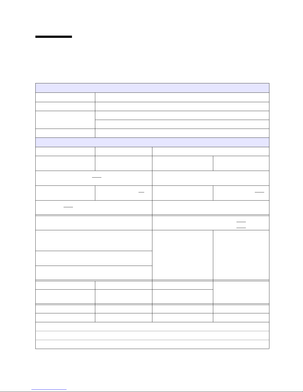
SL3000 Configuration Work Sheet
SL3000 Configuration Work Sheet
Enter the library and drive configurations in the table below.
TABLE 3-13 SL3000 Library Configuration
Account Information
Site Location Number: Account Name:
Address:
Contact phone numbers:
Library Information
Library S/N Library name Library IP addresses
. . .
Number of modules (Total): Total Number of Slots:
Activated Slots:
❏ DEM ❏ CEMs (How many? ) ❏ PEMs ❏ AEMs How many?
CAPs (Total): TallBots: ❏ 1 ❏ 2 (2 TallBots require 2 PEMs or AEMs)
Partitioned? ❏ Yes
❏ No
Host Interface ❏ Ethernet Host software Version:
❏ Fibre Channel ❏ ACSLS
Touch Screen
Operator Panel?
Web-launch SLC Server ❏ Other:
Power Configuration ❏ N+1 ❏ 2N DC Power Supplies
Circuit Breaker Locations:
❏ Yes
❏ No
❏ TCP/IP
❏ Fibre Channel
❏ HSC
. . .
How many?
How many?
Number of Tape Drives: T10000: A* ❏ B* ❏ T9840: C ❏ D* ❏ LTO: 3 ❏ 4* ❏
Encryption-capable*: ❏ Yes ❏ No ❏ Yes ❏ No ❏ Yes ❏ No
Comments:
316194102 • Revision: B Chapter 3 Site Planning 69

SL3000 Configuration Work Sheet
TABLE 3-13 SL3000 Library Configuration (Continued)
Base Module — Tape Drive Information
Drive Type (model) Drive Address Inte rface Type
(FC, FICON, ESCON)
1.
2.
3.
4.
5.
6.
7.
8.
9.
10.
11.
12.
13.
14.
15.
IP Address
. . .
. . .
. . .
. . .
. . .
. . .
. . .
. . .
. . .
. . .
. . .
. . .
. . .
. . .
. . .
16.
17.
18.
19.
20.
21.
22.
23.
24.
. . .
. . .
. . .
. . .
. . .
. . .
. . .
. . .
. . .
70 SL3000: Systems Assurance Guide • May 2010 Revision: B • 316194102

TABLE 3-13 SL3000 Library Configuration (Continued)
Drive Expansion Module — Tape Drive Information
SL3000 Configuration Work Sheet
Drive Type (model) Drive Address Inte rface Type
(FC, FICON, ESCON)
25.
26.
27.
28.
29.
30.
31.
32.
33.
34.
35.
36.
37.
38.
39.
IP Address
. . .
. . .
. . .
. . .
. . .
. . .
. . .
. . .
. . .
. . .
. . .
. . .
. . .
. . .
. . .
40.
41.
42.
43.
44.
45.
46.
47.
48.
49.
50.
51.
52.
53.
54.
55.
56.
. . .
. . .
. . .
. . .
. . .
. . .
. . .
. . .
. . .
. . .
. . .
. . .
. . .
. . .
. . .
. . .
. . .
316194102 • Revision: B Chapter 3 Site Planning 71

SL3000 Configuration Work Sheet
72 SL3000: Systems Assurance Guide • May 2010 Revision: B • 316194102

CHAPTER
4
Customer Site Survey
Use this chapter to prepare for the installation by reviewing the information and
completing the “Site Preparation Checklist” on page 74
Other information—surveys—in this chapter includes:
■ “System Configuration” on page 79
■ “Applications” on page 81
■ “Databases” on page 84
Existing
■ “Hardware Configurations” on page 85
■ “Library” on page 85
■ “Tape Drives” on page 86
■ “Data Cartridges” on page 87
■ “Network and Components” on page 88
■ “ESCON Directors” on page 90
■ “FICON Directors” on page 91
■ “Cables” on page 92
Interoperability
Important:
Not sure if your customer's software of choice supports StorageTek hardware?
Do the different network components support each other?
Check out the Interoperability Tool at: https://extranet.stortek.com/interop/interop
This tool is designed for connectivity information on al
regardless of the brand. It can assist in completing a product qualification form.
The configurations listed are reflective of th
from various sources, including testing labs and our technology partners.
The Interop Tool only lists configurations w
316194102 • Revision: B 73
l supported products sold
e most up-to-date information reported
ith valid connectivity, it does not validate.

Site Preparation Checklist
Site Preparation Checklist
Use the following checklist to ensure that the customer is ready to receive the library
and to ensure that you are ready to start the installation.
See Chapter 3, “Site Planning” for supporting information such as measurements,
weights, and service clearances.
TABLE 4-1 Site Preparation Checklist
Question Answer
Delivery and Handling
Does the customer have a delivery dock?
Yes ❏ No ❏
If not, where will the equipment be
delivered?
If a delivery dock is available,
what are the hours of operation?
Are there street or alley limitations that
Yes ❏ No ❏
may hinder the delivery?
For example: limited access, one-way
traffic, truck size?
Is the dock close to the computer room
Yes ❏ No ❏
where the equipment will be installed?
If no, how far does the equipment need to
be moved?
Is an elevator required to move the
Distance:
Yes ❏ No ❏
equipment to the appropriate floor?
What type of elevator is being used?
Description:
Such as: Class A or C, freight, low-rise,
passenger, service, hydraulic, pneumatic.
Comments
Important:
Check the delivery route that the library
must travel from the loading dock to the
installation location.
Make sure there are no obstructions and
that the library will fit through doors,
hallways, and into elevators.
What is the capacity of the elevator?
What are the dimensions of the elevator?
Are there any ramps or slopes that you
need to move equipment over to get to the
installation site?
What is the angle?
Will there be people available to handle the
number of, size of, and weight of the
shipping pallets?
Will there be equipment available to handle
the pallets (forklifts or pallet jacks)?
74 SL3000: Systems Assurance Guide • May 2010 Revision: B • 316194102
Yes ❏ No ❏
Degrees:
Yes ❏ No ❏
Yes ❏ No ❏

TABLE 4-1 Site Preparation Checklist (Continued)
Site Preparation Checklist
Question Answer
Is there a staging area where the pallets can
Yes ❏ No ❏
Comments
be placed with access to the installation
site?
Are there doorway or hallway height and
width limitations that may prevent moving
Yes ❏ No ❏
Note: The SL3000 is delivered with
casters and can roll into position.
the equipment on the shipping pallets?
Will you need to unpack the equipment to
move it to the installation site?
Yes ❏ No ❏
Physical Placement
The library does not require raised
flooring, but it is highly recommended.
Does the site have raised flooring?
Has the floor been laser-leveled?
Does the customer have floor tile cut-outs
Yes ❏ No ❏
Yes ❏ No ❏
Yes ❏ No ❏
available for AC power, interface cables,
and vented floor tiles?
Does the intended site have enough room
Yes ❏ No ❏
to install and service the equipment?
Can the customer’s floor support the
Yes ❏ No ❏
weight of the library configuration?
Are there plans for expansion?
If so, when?
What type of expansion?
How many slots does the customer
currently have?
How many expansion modules does the
customer currently have?
Can the customer’s floor support the
weight of future expansions?
Is the ceiling above the library clear of
obstructions such as smoke detectors,
sprinklers, and vents.
Does the equipment need to move over
carpet?
If so, is there protection from electrostatic
discharge (ESD)?
Yes ❏ No ❏
Date:
❏ Drives
❏ Cartridges
❏ Activation keys
Slots:
CEMs:
Yes ❏ No ❏
Yes ❏ No ❏
Yes ❏ No ❏
316194102 • Revision: B Chapter 4 Customer Site Survey 75

Site Preparation Checklist
TABLE 4-1 Site Preparation Checklist (Continued)
Question Answer
Comments
Environmental
Does the site meet the environmental
requirements for:
■ Tem pe rat ur e?
■ Relative Humidity?
■ Air flow (front, back, sides)?
■ Cooling requirements?
Does the site contain features and materials
Yes ❏ No ❏
Yes ❏ No ❏
Temperature: 16°–32°C (60°–90°F)
Humidity: 20–80%, non-condensing
Current measurements:
■ Temperature
■ Relative Humidity
that guard against electrostatic discharge?
Does the customer have a large dumpster
and means to dispose of the packing
Yes ❏ No ❏
material?
Are there special requirements to dispose
Yes ❏ No ❏
of or recycle the packing material, pallets,
and cardboard?
Is there concern about Seismic or
Yes ❏ No ❏
Earthquake ratings for the SL3000?
Power
Does the intended site meet the power
Yes ❏ No ❏
requirements of the equipment?
Have arrangements been made for a
qualified electrician to connect power?
Does the site have multiple, separate
circuits for power redundancy?
Does the customer plan to use multiple
branch circuits for redundancy?
Building Codes
Do local, city, state, or federal codes need
to be checked and approved for:
■ Wiring configurations?
■ Fire suppression requirements?
■ Clearances?
■ Safety?
Does the customer require a fire
suppression system?
Yes ❏ No ❏
Yes ❏ No ❏
Yes ❏ No ❏
Yes ❏ No ❏
Yes ❏ No ❏
Yes ❏ No ❏
Yes ❏ No ❏
Yes ❏ No ❏
For 2N power configurations only
The SL3000 supports a fire suppression
system; however, this is the
responsibility of the customer, their
insurance company, local fire
department, and building codes.
76 SL3000: Systems Assurance Guide • May 2010 Revision: B • 316194102
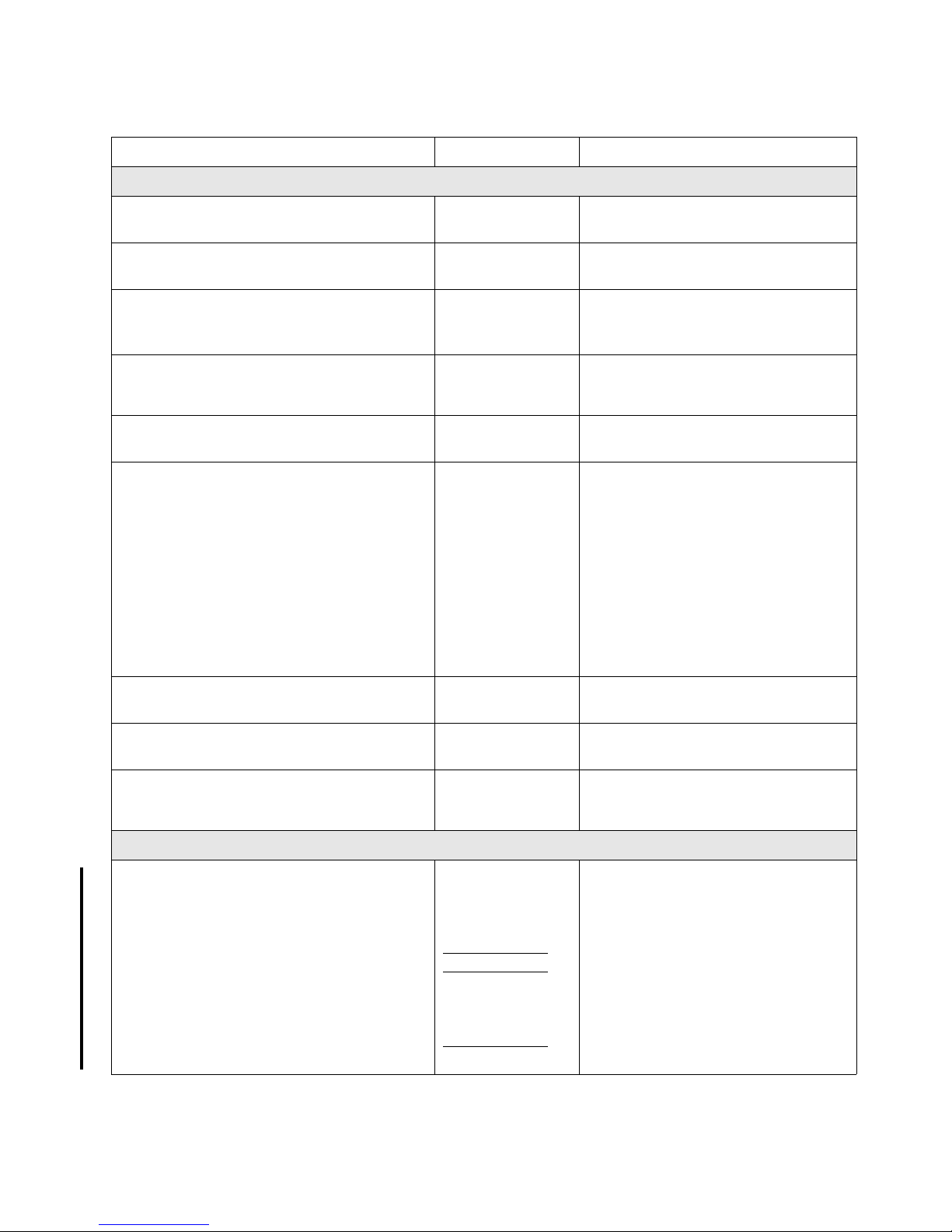
TABLE 4-1 Site Preparation Checklist (Continued)
Site Preparation Checklist
Question Answer
Comments
Connectivity
Is the customer using an Open Systems or
an Enterprise platform?
Have you completed the Site Survey
Open ❏
Enterprise ❏
Yes ❏ No ❏
forms?
Have you referred to the Interop Tool at
Yes ❏ No ❏
https://extranet.stortek.com/interop
/interop?
Does the customer want to install
equipment in the library rack space?
Have you completed a cable plan
Yes ❏ No ❏
Yes ❏ No ❏
Note: The SL3000 has limited rack space
and is for use with drive connectivity:
encryption and SDP.
(configuration drawing)?
Have you determined the type of and
Yes ❏ No ❏
number of cables required?
Library:
■ Ethernet: Host connections
■ Fibre Channel: Host connections
Tape dri v es:
■ Fibre Channel: Data path
■ FICON or ESCON: Data path
■ Ethernet: SDP or encryption
Is the customer prepared to supply
Yes ❏ No ❏
Ethernet cables for the network?
Can the customer provide the required
Yes ❏ No ❏
number of “static” IP addresses?
Will interface cables be run from outside
the computer room?
Yes ❏ No ❏
Cables that run outside a computer room
require flammability ratings of
CL2/CL2P.
Tape Dr i v es (See Appendix C, “Tape Drives and Media” on page 169)
Does the customer have the correct type
and number of tape drives?
Are new or additional drives required?
How many?
What types?
Are conversions required, such as drive
trays, or interface ports (SFPs)?
How many?
Yes ❏ No ❏
Yes ❏ No ❏
Yes ❏ No ❏
Supported Drives:
■ T10000A* and B*
■ T9840C and D*
■ LTO3, 4*, and 5*
* Encryption-capable
316194102 • Revision: B Chapter 4 Customer Site Survey 77
Site Preparation Checklist
TABLE 4-1 Site Preparation Checklist (Continued)
Question Answer
Comments
Media Factors (See Appendix C, “Tape Drives and Media” on page 169)
Does the customer have the correct type
Yes ❏ No ❏
and number of data cartridges?
Are additional cartridges required?
Are cleaning cartridges required?
Are labels required?
How many?
What types?
Does the customer need additional CAP
Yes ❏ No ❏
Yes ❏ No ❏
Yes ❏ No ❏
Yes ❏ No ❏
magazines, cartridge racks or furniture?
Human Interface
Are there any issues that may prevent
operators from entering the library?
Such as handicapped (wheel-chair),
too short to reach drives in the upper bays,
Yes ❏ No ❏
The width between the front and rear
walls is 45 cm (18 in.), which may be
difficult for some to move freely inside
the library.
too tall to easily enter the library.
Where will the remote operator panels
Yes ❏ No ❏
be located?
Remote Support
Will the customer allow StorageTek to use
Yes ❏ No ❏
remote support?
Has the SDP Systems Assurance Guide
Yes ❏ No ❏
been completed?
Has the SDP appliance and mounting
Yes ❏ No ❏
hardware been ordered?
Professional Services, Data Center Services, and Data Migration Services
Are Professional Services required for:
■ Assessments and Migration
■ Fire suppression systems
■ Media conversion services
■ Drive and media relocations
■ Network upgrades
■ Training
Is the customer moving existing products
Yes ❏ No ❏
Yes ❏ No ❏
Yes ❏ No ❏
Yes ❏ No ❏
Yes ❏ No ❏
Yes ❏ No ❏
Yes ❏ No ❏
and services to an SL3000 library?
78 SL3000: Systems Assurance Guide • May 2010 Revision: B • 316194102

System Configuration
The following two pages provide space where you can record information about the
customers’ operating systems and configurations.
TABLE 4-2 Operating System Survey
Question Answer
1. How many and what types of operating systems
or platforms does the customer have?
Open-Systems:
• Windows: 2000, NT...
Make & Model:
Quantity:
• UNIX: Solaris, AIX, HP-UX...
Make & Model:
Quantity:
System Configuration
• Linux...
Make & Model:
Quantity:
Mainframe:
•MVS
Make & Model:
Quantity:
•VM
Make & Model:
Quantity:
Other (Specify):
Make & Model:
Quantity:
2. Are there plans for:
•New purchases?
• Future upgrades?
•If so, what?
3. How many systems/servers are used as:
• Backup servers?
• File servers?
• Print servers?
• Exchange servers?
316194102 • Revision: B Chapter 4 Customer Site Survey 79

System Configuration
TABLE 4-3 System Configuration
System Processor Processor
Vendor Make & Model
Operating System Type
Version Number & Patch Level
Number of Channels
IP Address
HBA Vendor & Model
HBA Firmware Versions
Switch & Port Numbers
Switch Make & Model
ESCD and HCD support
ESCON Director Make & Model
ESCON Manager
FICON support
EREP
Ports
System Processor Processor
Vendor Make & Model
Operating System
Version Number & Patch Level
Number of Channels
IP Address
HBA Vendor & Model
HBA Firmware Versions
Switch & Port Numbers
Switch Make & Model
ESCD and HCD support
ESCON Director Make & Model
ESCON Manager
FICON support
EREP
Ports
80 SL3000: Systems Assurance Guide • May 2010 Revision: B • 316194102
 Loading...