

Page 1

SPARC T4-4 Server
Installation Guide
Part No.: E23414-06
May 2014
Page 2

Copyright ©2011, 2014 , Oracle and/or its affiliates.All rightsreserved.
FUJITSU LIMITEDprovided technicalinput andreview on portions of this material.
This softwareand related documentation are provided undera license agreement containing restrictions on use and disclosureand are protected by
intellectual propertylaws. Exceptas expressly permitted inyour licenseagreement or allowed by law, you may not use, copy, reproduce, translate,
broadcast, modify, license, transmit, distribute, exhibit, perform, publish, or display any part, in any form, or by any means. Reverse engineering,
disassembly, or decompilation of this software, unless requiredby lawfor interoperability, is prohibited.
The informationcontained hereinis subjectto changewithout noticeand isnot warrantedto beerror-free.If youfind anyerrors, please report them to us
in writing.
If thisis softwareor related software documentation that is delivered to the U.S. Government or anyone licensing it on behalf of the U.S. Government, the
following noticeis applicable:
U.S. GOVERNMENTEND USERS.Oracle programs,including anyoperating system,integrated software, any programs installed onthe hardware,
and/or documentation,delivered toU.S. Governmentend usersare "commercial computer software" pursuantto theapplicable FederalAcquisition
Regulation andagency-specific supplementalregulations. Assuch, use,duplication, disclosure, modification, andadaptation ofthe programs, including
any operatingsystem, integratedsoftware, anyprograms installed on the hardware,and/or documentation,shall besubject tolicense termsand license
restrictions applicableto theprograms. No other rights are granted to the U.S. Government.
This software or hardware is developed for general use in a variety ofinformation managementapplications. It is not developed or intended for usein any
inherently dangerous applications, includingapplications whichmay create a riskof personalinjury. If you use this software or hardwarein dangerous
applications, thenyou shallbe responsibleto takeall appropriate fail-safe, backup,redundancy, and other measuresto ensure its safeuse. Oracle
Corporation andits affiliatesdisclaim anyliability forany damagescaused byuse ofthis software or hardware in dangerous applications.
Oracle andJava areregistered trademarks of Oracle and/or its affiliates.Other namesmay betrademarks oftheir respective owners.
AMD, Opteron,the AMDlogo, andthe AMDOpteron logo are trademarks or registered trademarks of Advanced Micro Devices. Intel and Intel Xeon are
trademarks orregistered trademarks of Intel Corporation. All SPARC trademarks are used under license and aretrademarks orregistered trademarks of
SPARC International, Inc.UNIX isa registered trademark licensedthrough X/Open Company, Ltd.
This softwareor hardware and documentation may provide access to or information on content, products,and servicesfrom third parties. Oracle
Corporation andits affiliatesare not responsible for and expressly disclaimall warrantiesof anykind withrespect to third-party content, products,and
services. OracleCorporation andits affiliateswill notbe responsible for anyloss, costs,or damagesincurred due to your access to or use of third-party
content, products,or services.
Copyright ©2011, 2014, Oracle et/ou ses affiliés. Tous droits réservés.
Entrée etrevue tecnicalfournies parFUJITSU LIMITEDsur desparties dece matériel.
Ce logicielet ladocumentation quil’accompagne sontprotégés parles loissur lapropriété intellectuelle. Ils sont concédés sous licence et soumis à des
restrictions d’utilisationet dedivulgation. Saufdisposition devotre contrat de licence ou de la loi, vous ne pouvez pas copier, reproduire,traduire,
diffuser, modifier,breveter, transmettre, distribuer, exposer,exécuter,publier ouafficher le logiciel, même partiellement, sous quelque forme et par
quelque procédéque cesoit. Parailleurs, ilest interdit de procéder à touteingénierie inversedu logiciel,de ledésassembler oude ledécompiler,excepté à
des finsd’interopérabilité avecdes logicielstiers outel queprescrit par la loi.
Les informationsfournies dansce documentsont susceptiblesde modificationsans préavis.Par ailleurs,Oracle Corporationet FUJITSULIMITED ne
garantit pasqu’elles soientexemptes d’erreurset vousinvite, lecas échéant,à luien faire part parécrit.
Si celogiciel, oula documentationqui l’accompagne,est concédésous licenceau Gouvernementdes Etats-Unis,ou àtoute entitéqui délivrela licencede
ce logicielou l’utilisepour lecompte duGouvernement desEtats-Unis, lanotice suivantes’applique :
U.S. GOVERNMENTEND USERS.Oracle programs,including anyoperating system,integrated software, any programs installed onthe hardware,
and/or documentation,delivered toU.S. Governmentend usersare "commercial computer software" pursuantto theapplicable FederalAcquisition
Regulation andagency-specific supplementalregulations. Assuch, use,duplication, disclosure, modification, andadaptation ofthe programs, including
any operatingsystem, integratedsoftware, anyprograms installed on the hardware,and/or documentation,shall besubject tolicense termsand license
restrictions applicableto theprograms. No other rights are granted to the U.S. Government.
Ce logicielou matériela étédéveloppé pourun usagegénéral dansle cadred’applications degestion desinformations. Celogiciel oumatériel n’estpas
conçu nin’est destinéà êtreutilisé dansdes applicationsà risque,notamment dansdes applicationspouvant causerdes dommagescorporels. Si vous
utilisez celogiciel oumatériel dansle cadred’applications dangereuses, il estde votre responsabilité de prendre toutes les mesures desecours, de
sauvegarde, deredondance et autres mesures nécessaires à sonutilisation dansdes conditionsoptimales desécurité. OracleCorporation etses affiliés
déclinent touteresponsabilité quantaux dommagescausés parl’utilisation dece logicielou matérielpour cetype d’applications.
Oracle etJava sontdes marquesdéposées d’OracleCorporation et/oude sesaffiliés.Tout autre nom mentionné peut correspondre à desmarques
appartenant àd’autres propriétaires qu’Oracle.
Fujitsu etle logoFujitsu sontdes marquesdéposées deFujitsu Limited.
AMD, Opteron,le logoAMD etle logoAMD Opteron sont desmarques ou des marques déposées d’Advanced MicroDevices. Intelet IntelXeon sontdes
marques oudes marques déposées d’IntelCorporation. Toutes lesmarques SPARCsont utiliséessous licenceet sontdes marquesou desmarques
déposées deSPARC International, Inc.UNIX estune marque déposée concédée sous licence par X/Open Company, Ltd.
Ce logicielou matérielet ladocumentation quil’accompagne peuventfournir desinformations oudes liensdonnant accèsà descontenus, desproduits et
des servicesémanant detiers. OracleCorporation etses affiliéset FUJITSULIMITED déclinenttoute responsabilité ou garantieexpresse quant aux
contenus, produitsou servicesémanant detiers. Enaucun cas,Oracle Corporationet sesaffiliés et FUJITSU LIMITED ne sauraient être tenus pour
responsables despertes subies,des coûtsoccasionnés oudes dommagescausés parl’accès àdes contenus,produits ou services tiers, ou à leur utilisation.
Please
Recycle
Page 3

Contents
Using This Documentation vii
Confirming Server and Site Specifications 1
Server Overview 1
Front Panel Components 3
Rear Panel Components 4
Confirming Specifications 5
Physical Specifications 5
Minimum Clearance for Service Access 6
Electrical Specifications 6
Input Power Information 7
Environmental Requirements 8
Acoustic Noise Emissions 9
Preparing for Installation 11
Shipping Kit 11
Handling Precautions 13
ESD Precautions 13
Tools Needed for Installation 14
Installing the Server 15
Install Optional Components 16
Rack Compatibility 16
iii
Page 4

Rackmount Kit 17
▼ Determine Correct Rackmount Hardware 19
▼ Mark the Rackmounting Location 19
▼ Install the Rackmount Hardware 20
▼ Install the Server 24
Installing the Shipping Bracket Assembly (Optional) 26
Shipping Bracket Kit 26
▼ Determine Correct Shipping Bracket Fasteners 27
▼ Install the Front Shipping Bracket 28
▼ Install the Rear Shipping Bracket 29
▼ Remove the Front Shipping Bracket 30
Installing the CMA (Optional) 30
CMA Kit 31
▼ Determine Correct CMA Hardware 31
▼ Install the CMA 32
Connecting the Server Cables 35
Cabling Requirements 35
Identifying Ports 37
USB Ports 37
SER MGT Ports 38
NET MGT Port 38
Gigabit-Ethernet Ports 39
QSFP Port 39
VGA Port 40
Connecting Data and Management Cables 40
▼ Connect the SER MGT Cable 41
▼ Connect the NET MGT Cable 41
▼ Connect the Ethernet Network Cables 42
iv SPARC T4-4 Server Installation Guide • May 2014
Page 5

▼ Connect Other Data Cables 42
▼ Secure Cables Using the CMA 42
Powering On the Server for the First Time 45
▼ Connect a Terminal or Emulator to the SER MGT Port 46
▼ Prepare Power Cords 46
▼ Power On the System for the First Time 47
Oracle Solaris OS Configuration Parameters 49
Assigning a Static IP Address to the SP 50
Oracle ILOM System Console Overview 51
▼ Log In to the SP (SER MGT Port) 51
▼ Assign a Static IP Address to the NET MGT Port 52
Booting the Oracle Solaris Operating System 55
▼ Boot the Oracle Solaris Operating System 56
▼ Avoid Booting the Oracle Solaris Operating System at Start Up 57
▼ Reset the Server 57
▼ Power Cycle the Server 57
Index 59
Contents v
Page 6

vi SPARC T4-4 Server Installation Guide • May 2014
Page 7

Using This Documentation
This document provides specifications, and describes how to install and configure
Oracle’s SPARC T4-4 server.
Note – All internal components except hard drives must be installed by qualified
service technicians only.
■ “Related Documentation” on page vii
■ “Feedback” on page viii
■ “Support and Accessibility” on page viii
Related Documentation
Documentation Links
All Oracle products http://www.oracle.com/documentation
SPARC T4-4 server http://www.oracle.com/pls/topic/lookup?ctx=
Oracle Integrated
Lights Out Manager (ILOM)
Oracle Solaris 11 OS http://www.oracle.com/goto/Solaris11/docs
Oracle Solaris 10 OS http://www.oracle.com/goto/Solaris10/docs
SPARCT4-4
http://www.oracle.com/goto/ILOM/docs
vii
Page 8

Documentation Links
Oracle VM Server for SPARC http://www.oracle.com/goto/VM-SPARC/docs
Oracle VTS http://www.oracle.com/goto/VTS/docs
Oracle Enterprise Manager
Ops Center
Feedback
Provide feedback on this documentation at:
http://www.oracle.com/goto/docfeedback
Support and Accessibility
Description Links
Access electronic support
through My Oracle Support
http://support.oracle.com
For hearing impaired:
http://www.oracle.com/accessibility/support.html
http://www.oracle.com/pls/topic/lookup?ctx=
oc122
Learn about Oracle’s
commitment to accessibility
viii SPARC T4-4 Server Installation Guide • May 2014
http://www.oracle.com/us/corporate/accessibility/index.html
Page 9

Confirming Server and Site
Specifications
These topics provide background information needed to install the SPARC T4-4
server.
Step Description Links
1 Review the SPARC T4-4 Server Product Notes for
any late-breaking news.
Review the server features, components, LEDs
and ports.
Review server specifications and site
requirements.
Related Information
■ “Installing the Server” on page 15
Server Overview
The SPARC T4-4 is a 5-rack unit (5U) server.
SPARC T4-4 Server Product Notes
“Front Panel Components” on page 3
“Rear Panel Components” on page 4
“Server Overview” on page 1
“Confirming Specifications” on page 5
1
Page 10
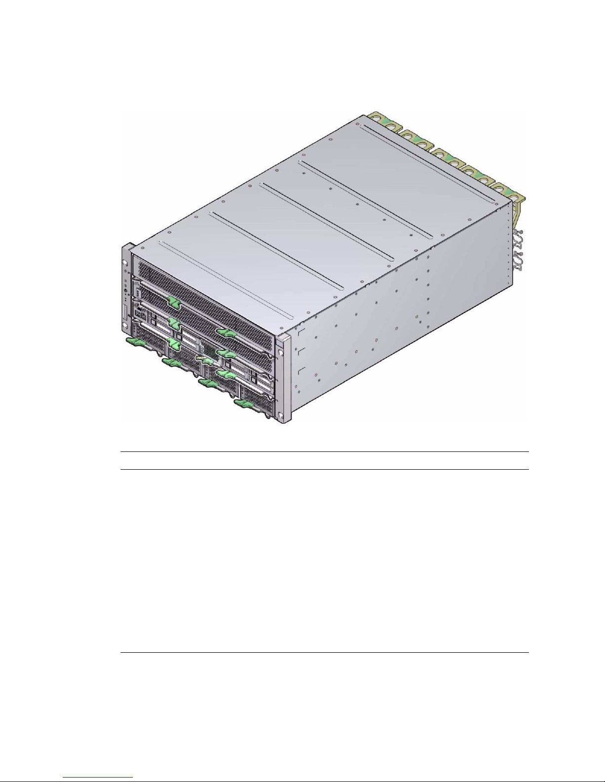
FIGURE: SPARC T4-4 Server
Component/Function New Characteristics
Processor Up to 4x SPARC T4, 16-core chip multiprocessor (CMP) with 8
threads per core.
2x multiprocessor configuration also available.
Memory 16x DDR3 DIMM slots; 4 Gbyte, 8 Gbyte, and 16 GByte capacity
modules.
I/O - Expansion 16x PCIe Gen2 card slots.
4x Gigabit Ethernet ports.
4x external USB ports.
Optional 8x 10-Gigabit Ethernet ports.
Hard drive storage 8-disk capable backplane. Any mix of hard drives and solid state
drives supported
Service processor Modular, pluggable on the motherboard.
2 SPARC T4-4 Server Installation Guide • May 2014
Page 11
Related Information
■ “Confirming Specifications” on page 5
■ “Shipping Kit” on page 11
■ “Handling Precautions” on page 13
■ “Tools Needed for Installation” on page 14
Front Panel Components
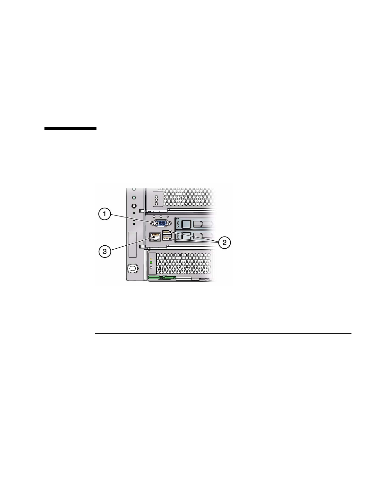
FIGURE: Front Panel connectors
Figure Legend
1 VGA port
2 USB ports
3 SER MGT port
Related Information
■ “Cabling Requirements” on page 35
■ “Server Overview” on page 1
■ “Rear Panel Components” on page 4
Confirming Server and Site Specifications 3
Page 12
Rear Panel Components
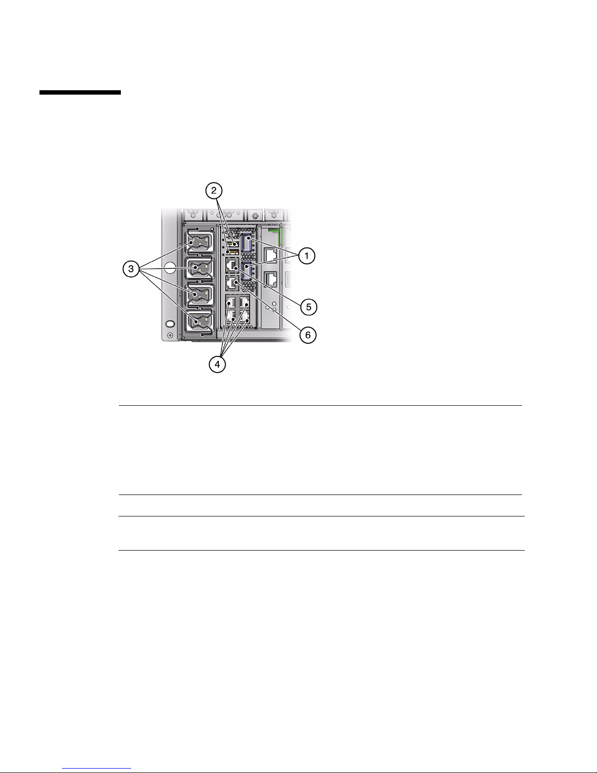
FIGURE: Rear Panel Connectors
Figure Legend
1 QCFP ports
2 USB ports
3 AC power ports
4 10-Gigabit Ethernet ports
5 SER MGT port
6 NET MGT Port
Note – You must follow the proper sequence when connecting cables to the server.
Do not connect the power cords until all data cables have been connected.
Related Information
■ “Front Panel Components” on page 3
■ “Cabling Requirements” on page 35
■ “Install the CMA” on page 32
■ “Secure Cables Using the CMA” on page 42
4 SPARC T4-4 Server Installation Guide • May 2014
Page 13

Confirming Specifications
These topics include server physical, environmental, and electrical specifications.
■ “Physical Specifications” on page 5
■ “Minimum Clearance for Service Access” on page 6
■ “Electrical Specifications” on page 6
■ “Input Power Information” on page 7
■ “Environmental Requirements” on page 8
■ “Acoustic Noise Emissions” on page 9
Related Information
■ “Server Overview” on page 1
■ “Handling Precautions” on page 13
■ “ESD Precautions” on page 13
■ “Install Optional Components” on page 16
■ “Identifying the Server Ports” on page 59
Physical Specifications
Description U.S. Metric
Width 17.5 in. 445 mm
Depth 27.6 in. 700 mm
Height 8.62 in. (5U) 219 mm
Weight, approximate
(without rackmount kit)
Related Information
■ “Electrical Specifications” on page 6
■ “Minimum Clearance for Service Access” on page 6
■ “Input Power Information” on page 7
■ “Environmental Requirements” on page 8
175 lb (max.) 79 kg (max.)
Confirming Server and Site Specifications 5
Page 14

Minimum Clearance for Service Access
Description US Metric
Minimum service access clearance (front) 36 in. 91 cm
Minimum service access clearance (rear) 36 in. 91 cm
Related Information
■ “Physical Specifications” on page 5
Electrical Specifications
The SPARC T4-4 server has four autoranging power supplies. To ensure redundant
operation of the power supplies, connect the power cords to at least two separate AC
circuits.
Use these specifications only as a general planning guide. To determine power values
based on expected workloads, use the SPARC T4-4 power calculator located at this
online site:
http://www.oracle.com/goto/powercalculators/
Description Specification
General Specifications
Operating input voltage range 200 to 240 VAC, 50 to 60 Hz (VAC tolerance +/- 10%)
Maximum operating input current
at 200 VAC
Maximum operating input power at
200 VAC
Maximum heat dissipation 9362 BTU/hour
Maximum standby power 42 W
Maximum Server Configuration Specifications
Under Nominal Temperature and Voltage Conditions
4 CMP, 1.65 GHz, 64 cores, 64 x 16-GByte DDR3 DIMMs, 8 HDDs, 16 I/O cards
Idle AC input power 1782 W
14.1 A
2770 W
9878 KJ/hour
6 SPARC T4-4 Server Installation Guide • May 2014
Page 15

Description Specification
Peak AC input power running
SpecJBB
Minimum Server Configuration Specifications
Under Nominal Temperature and Voltage Conditions
2 CMP, 1.65 GHz, 32 cores, 16 x 4-GByte DDR3 DIMMs, no HDDs, no I/O cards
Idle AC input power 950.0 W
Peak AC input power running
SpecJBB
2744 W
1287 W
Related Information
■ “Input Power Information” on page 7
■ “Environmental Requirements” on page 8
■ SPARC T4-4 Server Service Manual
Input Power Information
The maximum operating input current values are based on the formula
P / (V *0.90), where P = maximum operating input power and V=input voltage. For
example: 620W / (100V * 0.90) = 6.89A. You can use this formula to calculate the
maximum operating current at your input voltage.
Related Information
■ “Electrical Specifications” on page 6‘
Confirming Server and Site Specifications 7
Page 16

Environmental Requirements
Specification Operating Nonoperating
Temperature • Sea level to 2953 ft. (900m):
41°Fto95°F(5°Cto35°C)
• Above 2953 ft. (900m):
Decrease the maximum allowable
temperature by 1.6°F/1000 ft
(1°C/300m)
IEC 60068-2-1 Test Ad, and
60068-2-2 Test Bd
-40°F to 149°F (-40°Cto65°C)
IEC 60068-2-1 Test Ab and 60068-2-2
Test Bb
Relative
Humidity
10 to 90% RH, 27°C maximum wet
bulb (noncondensing)
IEC 60068-2-56 Test Cb
Altitude 10,000 ft. (3,000m)
*
IEC 60068-2-13 Test M, and
60068-2-41 Test Z/BM
Vibration 0.15 G (z-axis),
0.10 G (x-, y-axes), 5-500Hz swept
sine
IEC 60068-2-6 Test Fc
Shock 3 Gs, 11 ms half-sine
IEC 60068-2-27 Test Ea
93% RH, 35°C maximum wet bulb
(noncondensing)
IEC 60068-2-56 Test Cb
40,000 ft. (12,000m)
IEC 60068-2-13 Test M
0.5 G (z-axis),
0.25 G (x-, y-axes), 5-500Hz swept
sine
IEC 60068-2-6 Test Fc
• Roll-off:
1-inch roll-off free fall, front to back
rolling directions
• Threshold:
25 mm threshold height at 0.75 m/s
impact velocity
ETE-1010-02 Rev A
* Except in China markets where regulations may limit installations to a maximum altitude of 2000 m.
Related Information
■ “Physical Specifications” on page 5
■ “Input Power Information” on page 7
8 SPARC T4-4 Server Installation Guide • May 2014
Page 17

Acoustic Noise Emissions
Declared noise emissions for the SPARC T4-4 server is in accordance with ISO 9296
standards.
Operating at
Description
Operating at
Idle
Maximum
Power
Sound power level,
LwAd (1 B = 10 dB)
Sound Pressure Level,
LpAm (bystander positions)
Related Information
■ “Input Power Information” on page 7
■ “Environmental Requirements” on page 8
7.4 B 8.2 B
63 dBA 68.2 dBA
Confirming Server and Site Specifications 9
Page 18

10 SPARC T4-4 Server Installation Guide • May 2014
Page 19

Preparing for Installation
These topics provide background information needed to install the SPARC T4-4
server.
Step Description Links
3 Confirm that you have received all the items
you ordered.
Familiarize yourself with ESD and safety
precautions.
Make sure you have the correct tools for
installation.
4 When ready, begin server installation.. “Installing the Server” on page 15
“Shipping Kit” on page 11
“Handling Precautions” on page 13
“ESD Precautions” on page 13
“Tools Needed for Installation” on page 14
Related Information
■ “Installing the Server” on page 15
Shipping Kit
FIGURE: Shipping Kit on page 12 illustrates the components that are shipped with
the server.
11
Page 20
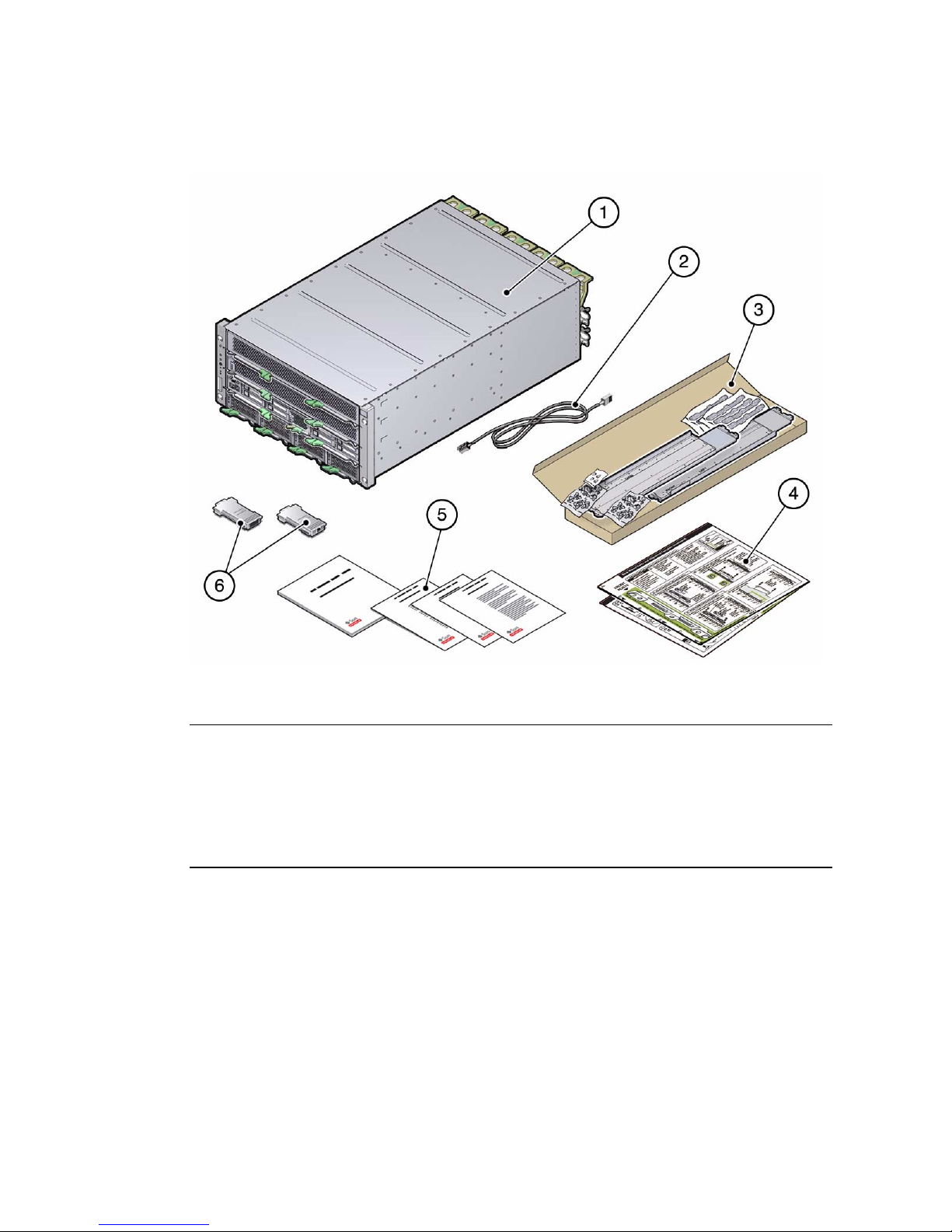
FIGURE: Shipping Kit
Figure Legend
1 SPARC T4-4 Server
2 Ethernet cable
3 Rackmount kit
4 Rackmount template
5 Print document kit
6 Cable adaptors
Related Information
■ “Server Overview” on page 1
■ “Rackmount Kit” on page 17
12 SPARC T4-4 Server Installation Guide • May 2014
Page 21

Handling Precautions
Caution – Deploy the anti-tilt bar on the equipment rack before beginning an
installation.
Caution – Always load equipment into a rack from the bottom up so that it will not
become top-heavy and tip over.
Caution – A fully configured SPARC T4-4 server weighs approximately 175 lb.
(79 kg). An equipment lift is required to lift and mount this server into a rack
enclosure when using the procedures in this document.
Caution – Always communicate your intentions clearly before, during, and after
each step of the rackmounting procedure to minimize confusion.
Related Information
■ “ESD Precautions” on page 13
ESD Precautions
Electronic equipment is susceptible to damage by static electricity. Use a grounded
antistatic wriststrap, footstrap, or equivalent safety equipment to prevent
electrostatic damage when you install or service the server.
Caution – To protect electronic components from electrostatic damage, which can
permanently disable the server or require repair by service technicians, place
components on an antistatic surface, such as an antistatic discharge mat, an antistatic
bag, or a disposable antistatic mat. Wear an antistatic grounding strap connected to a
metal surface on the chassis when you work on server components.
Preparing for Installation 13
Page 22

Related Information
■ “Handling Precautions” on page 13
Tools Needed for Installation
To install the server, you must have the following tools:
■ Long No. 2 Phillips screwdriver
■ Cutters or heavy-duty scissors
■ Marking pen or tape
■ ESD mat and grounding strap
■ Hydraulic or mechanical lift
In addition, you must provide a system console device, such as one of the following:
■ ASCII terminal
■ Workstation
■ Terminal server
■ Patch panel connected to a terminal server
Related Information
■ “Handling Precautions” on page 13
■ “ESD Precautions” on page 13
14 SPARC T4-4 Server Installation Guide • May 2014
Page 23

Installing the Server
These topics describe how to install the server into an equipment cabinet equipped
with square mounting holes. If you are installing the server into a cabinet equipped
with round mounting holes, see “Determine Correct Rackmount Hardware” on
page 19.
Note – If your rackmount kit came with its own instructions, use the instructions in
your rackmount kit instead of the instructions in this chapter. After performing the
server installation, proceed to “Powering On the Server for the First Time” on
page 45 for first-time power on.
If you are shipping the equipment rack to another location for final installation, or
installing the server into a vehicle, install the shipping bracket assembly. See
“Installing the Shipping Bracket Assembly (Optional)” on page 26.
Step Description Links
1 Install optional components. “Install Optional Components” on page 16
2 Ensure that your rack is compatible
with the server requirements.
3 Determine the correct rackmounting
hardware and install the hardware.
4 Install the server in the rack. “Install the Server” on page 24
5 If you are installing the server into a
vehicle or into a rack that will be
shipped to another location, install
the Shipping Bracket Assembly.
6 (Optional) Install the CMA. “Installing the CMA (Optional)” on
“Rack Compatibility” on page 16
“Determine Correct Rackmount
Hardware” on page 19
“Mark the Rackmounting Location” on
page 19
“Install the Rackmount Hardware” on
page 20
“Installing the Shipping Bracket Assembly
(Optional)” on page 26
page 30
15
Page 24

Step Description Links
7 Review cabling requirements and
port information. Attach data and
management cables to the server.
8 Configure the Oracle ILOM SP and
power on the server for the first time.
“Connecting the Server Cables” on page 35
“Powering On the Server for the First
Time” on page 45
Related Information
■ “Confirming Server and Site Specifications” on page 1
■ “Installing the Server” on page 15
Install Optional Components
The standard components of the server are installed at the factory. However, if you
ordered options such as additional memory or PCI cards, these will be shipped
separately. If possible, install these components prior to installing the server in a
rack. See the SPARC T4-4 Server Service Manual for specific installation instructions.
Note – The list of optional components can be updated without notice. See the
product web pages for the most current list of components supported in the server.
Rack Compatibility
The rackmount kit is compatible with equipment racks that meet the following
standards:
■ Four-post structure (mounting at both front and rear).
Note – Two-post racks are not compatible.
■ Rack horizontal opening and unit vertical pitch conforming to ANSI/EIA
310-D-1992 or IEC 60927 standards.
■ Distance between front and rear mounting planes between 24 to 36 inches
(65 cm and 91.5 cm).
16 SPARC T4-4 Server Installation Guide • May 2014
Page 25

■ Minimum clearance depth (to front cabinet door) in front of front rackmount
plane: 1 inch (25.4 mm).
■ Minimum clearance depth (to rear cabinet door) behind front rackmount plane:
34.6 inches (88 cm) with cable management assembly (recommended) or 31.5 inches
(80 cm) without the cable management assembly.
■ Minimum clearance width (between structural supports and cable troughs)
between front and rear mounting planes: 18.9 inches (48 cm).
Related Information
■ “Tools Needed for Installation” on page 14
■ “Rackmount Kit” on page 17
■ “Determine Correct Rackmount Hardware” on page 19
Rackmount Kit
The rackmount kit has two shelf rails, one for each side of the rack. Each shelf rail is
marked LEFT or RIGHT.(FIGURE: Rackmount Kit on page 18).
The shelf rails are mounted to the rack or cabinet with four adaptor brackets. The shelf
rails adjust to fit rack depths from 25 to 34.25 in. (63.5 to 87 cm).
Installing the Server 17
Page 26
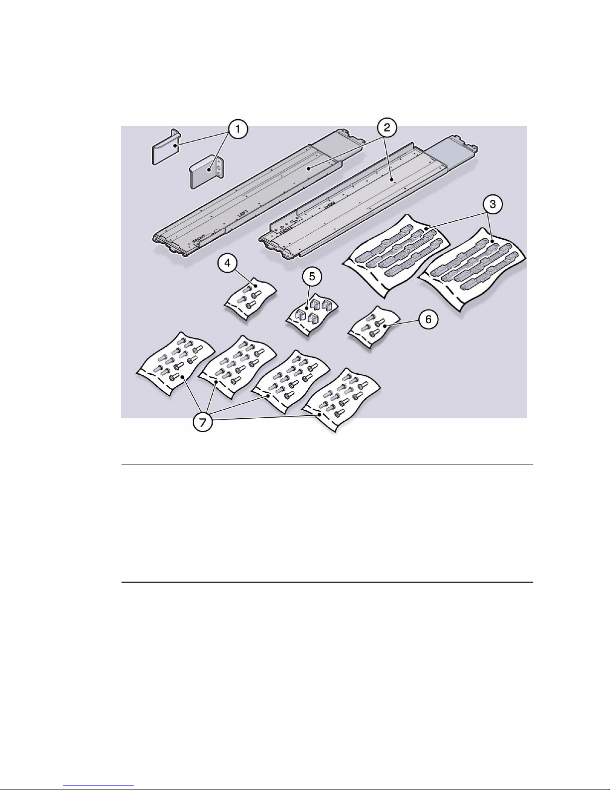
FIGURE: Rackmount Kit
Figure Legend
1 Upper rear brackets
2 Shelf rails
3 Adaptor brackets (two types provided, for cabinets with either square mounting holes or round
mounting holes)
4 Flathead screws
5 Threaded inserts
6 M6 screws
7 Rackmount screws
Related Information
■ “Tools Needed for Installation” on page 14
■ “Installing the Rackmount Kit” on page 13
■ “Rack Compatibility” on page 16
■ “Determine Correct Rackmount Hardware” on page 19
18 SPARC T4-4 Server Installation Guide • May 2014
Page 27

■ “Installing the Shipping Bracket Assembly (Optional)” on page 26
▼ Determine Correct Rackmount
Hardware
● Use the following table to determine the hardware needed for your rack
installation.
Cabinet Type Fastener Bags Required
Square hole SCREW, SEMS, M6 X 16
CAGENUTS, M6
SCREW, FLAT HEAD, M4 X 10
Round hole (10-32) with corner bezel SCREW, SEMS, 10-32 X 10
SCREW, FLAT HEAD, M4 X 10
Round hole (M6) with corner bezel SCREW, SEMS, M6 X 12
SCREW, FLAT HEAD, M4 X 10
Round hole (10-32) inside installation SCREW, SHOULDER, 10-32
SCREW, FLAT HEAD, M4 X 10
Round hole (M6) inside installation SCREW, SEMS, M6 X 12
SCREW, FLAT HEAD, M4 X 10
Note – Some of the fastener bags that are included in the kit are not required to
install this server.
▼ Mark the Rackmounting Location
Use the rackmounting template to identify the correct mounting holes for the shelf
rails.
Note – Load the rack from bottom to top.
Installing the Server 19
Page 28
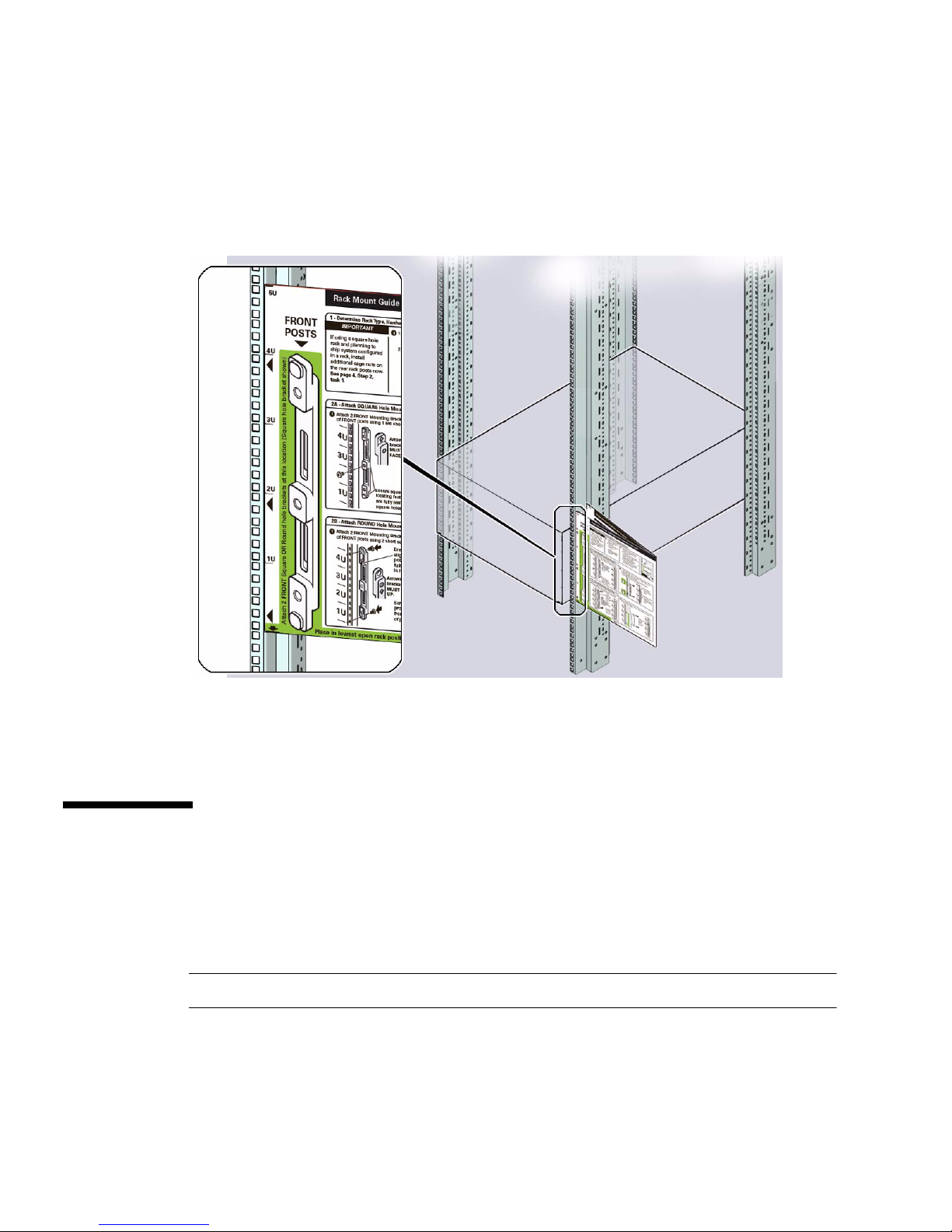
1. Ensure that there is enough vertical space in the cabinet to install the server.
2. Place the rackmounting template against the front rails.
The bottom edge of the template corresponds to the bottom edge of the server.
Measure up from the bottom of the template.
3. Mark the mounting holes for the front shelf rails.
4. Mark the mounting holes for the rear shelf rails.
▼ Install the Rackmount Hardware
1. Repeat the following steps for both the left and right front mounting points:
a. Place the adaptor bracket in the marked location.
Note – An “up” arrow indicates proper orientation.
b. Secure the adaptor bracket, with one No. 2 Phillips screw in the center hole.
c. Insert a mounting clip in the hole just above the top of the rack rail bracket.
20 SPARC T4-4 Server Installation Guide • May 2014
Page 29
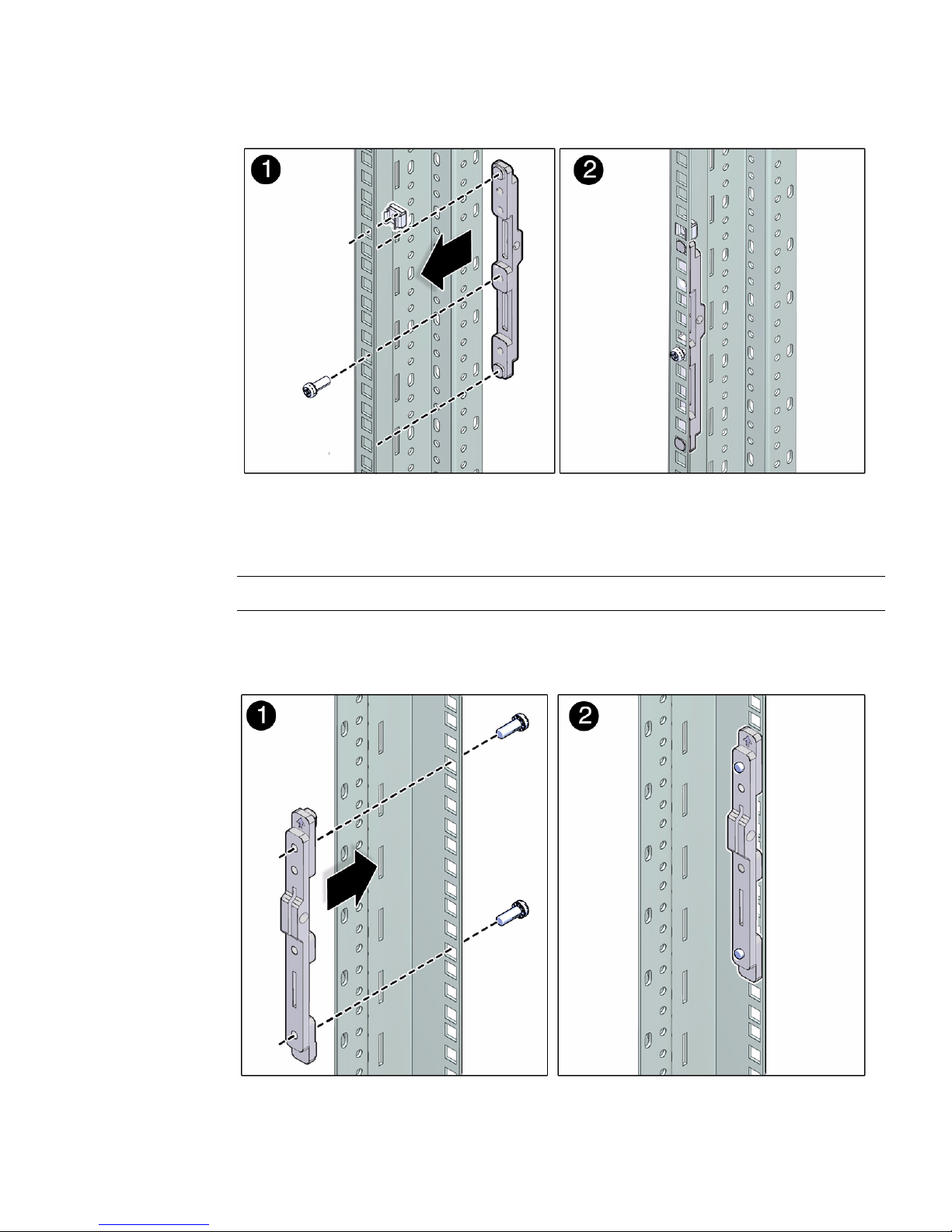
2. Repeat the following steps for both the left and right rear mounting points:
a. Place the adaptor bracket in the marked location.
Note – An “up” arrow indicates proper orientation.
b. Secure the adaptor bracket top and bottom holes, with two No. 2 Phillips
screws.
Installing the Server 21
Page 30
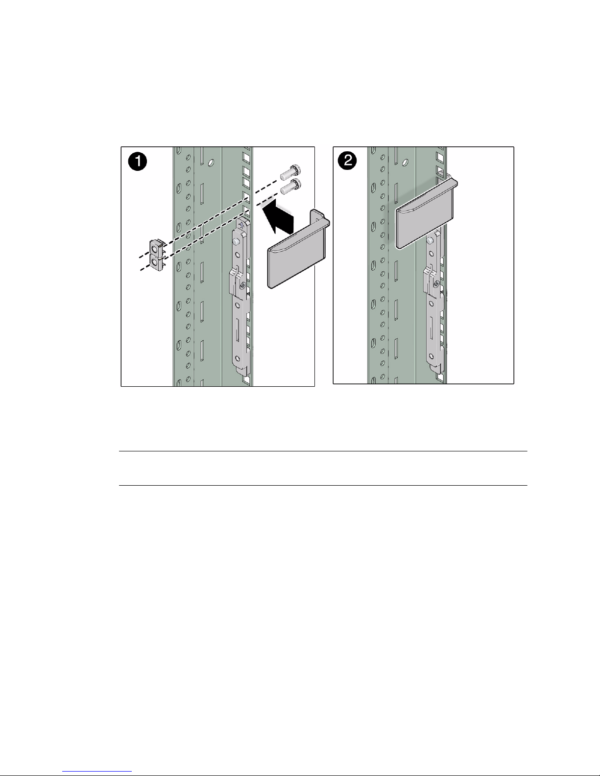
3. Install the left and right upper corner brackets.
a. Install two cage nuts into the cabinet in the two holes above the tops of the
adaptor brackets.
b. Secure each upper curner bracket with two No. 2 Phillips screws.
4. Install the shelf rails.
Note – The shelf rails are marked “Left” and “Right” (as viewed from the front of
the server) and “Front” and “Rear.”
Repeat for left and right shelf rails:
a. Insert the front of the shelf rail into the front adaptor bracket.
b. Insert the rear of the shelf rail into the rear adaptor bracket.
The shelf rail slides in and out to fit cabinets of different depths.
22 SPARC T4-4 Server Installation Guide • May 2014
Page 31
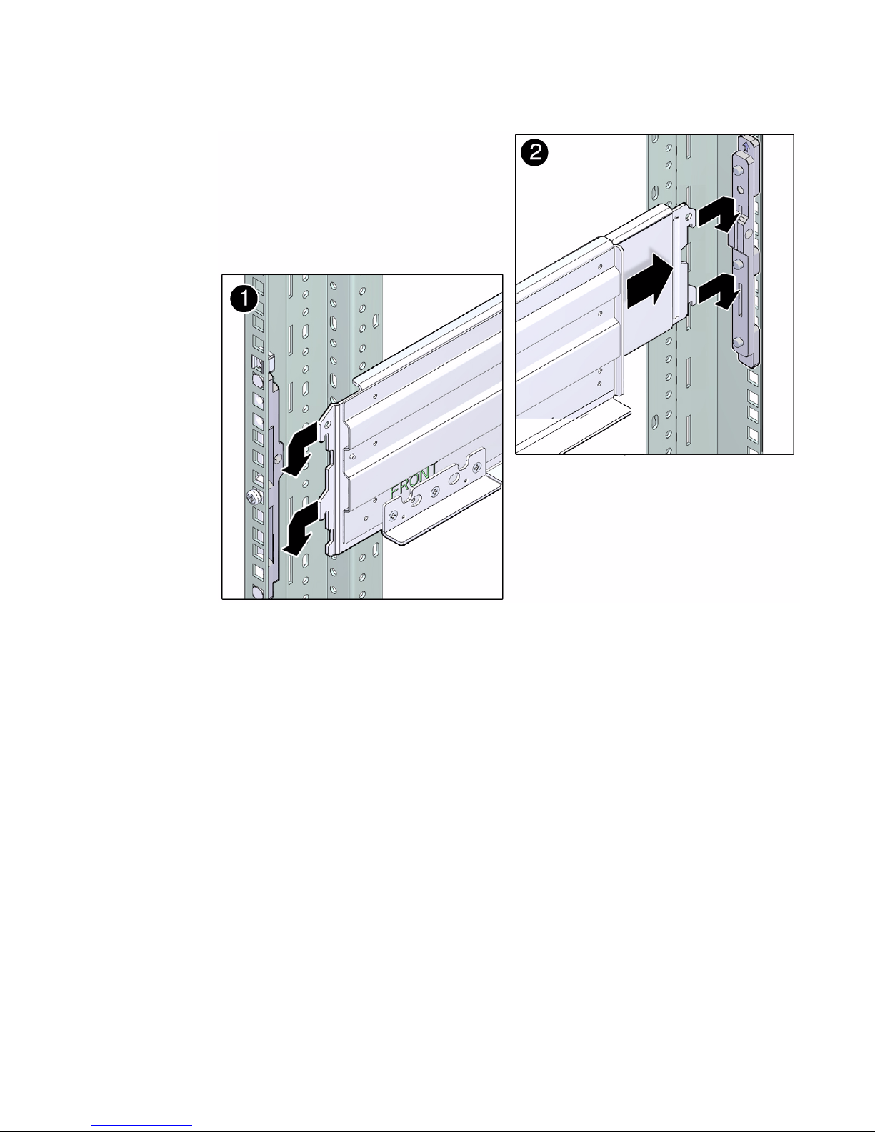
c. Secure each shelf rail with two flat-head No. 2 Phillips screws.
Installing the Server 23
Page 32

▼ Install the Server
Caution – A fully configured server weighs 175 lbs (80 kg). Use a mechanical lift to
install the server into the rack.
1. Ensure the mechanical lift is level and stable.
2. Lift the server up to the correct height.
3. Slide the server into the rack.
Ensure that the bottom edge of the server has cleared the bottom of the rack rails.
24 SPARC T4-4 Server Installation Guide • May 2014
Page 33
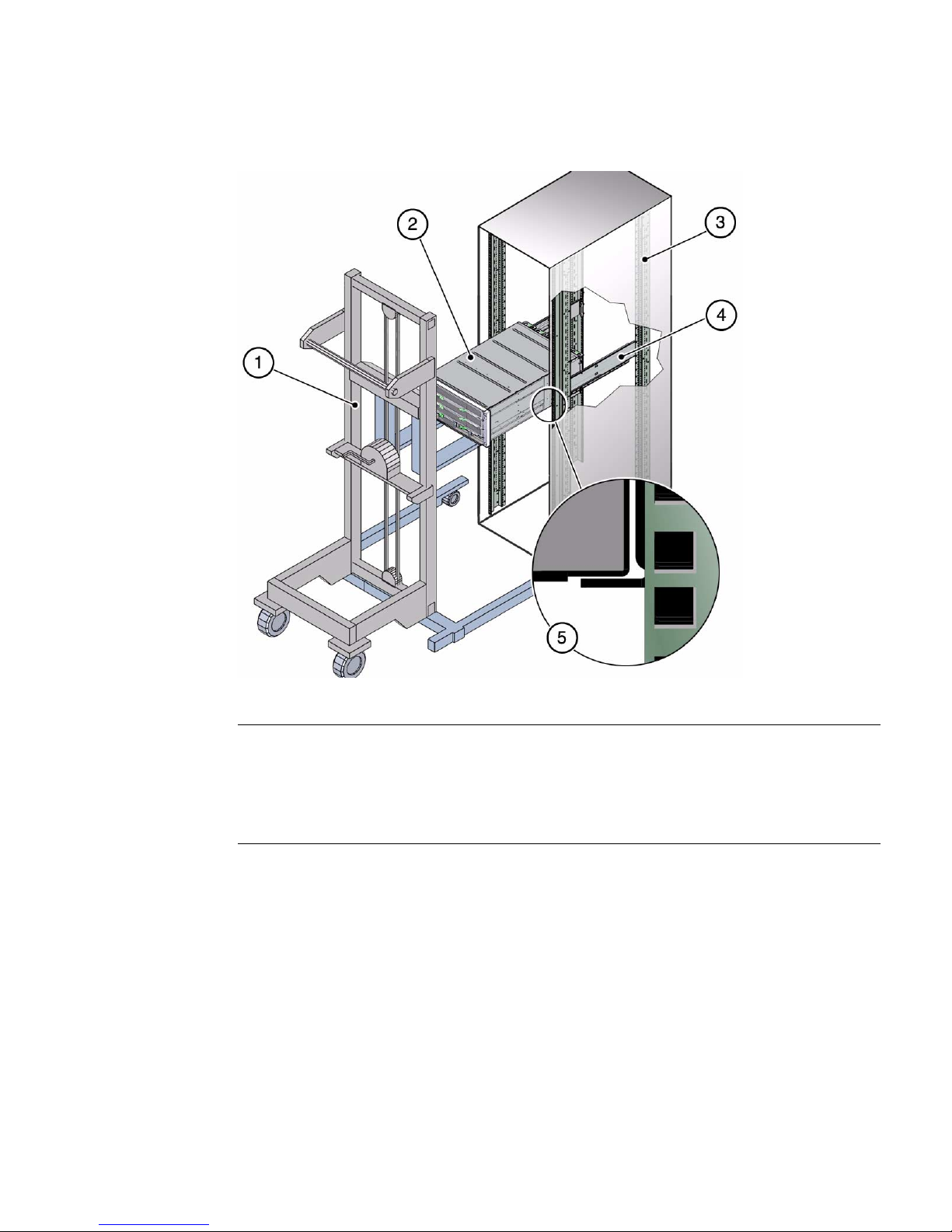
FIGURE: Installing the Server
Figure Legend
1 Mechanical lift
2 SPARC T4-4 server
3 Cabinet
4 Shelf rail
5 Ensure server mounted above shelf rail
4. Secure the server to the front panel using four No. 2 Phillips screws.
Installing the Server 25
Page 34

Installing the Shipping Bracket
Assembly (Optional)
Use this set of procedures if you are installing the server into an equipment rack that
will be shipped to another location, or if you are installing the server into a vehicle.
Note – This procedure describes how to install the server into a cabinet with square
mounting holes. If you are installing the server into a cabinet with round mounting
holes, see “Determine Correct Rackmount Hardware” on page 19.
This topic includes the following sections:
■ “Shipping Bracket Kit” on page 26
■ “Determine Correct Shipping Bracket Fasteners” on page 27
■ “Install the Front Shipping Bracket” on page 28
■ “Install the Rear Shipping Bracket” on page 29
Related Information
■ “Rack Compatibility” on page 16
■ “Rackmount Kit” on page 17
■ “Determine Correct Rackmount Hardware” on page 19
■ “Mark the Rackmounting Location” on page 19
■ “Install the Server” on page 24
Shipping Bracket Kit
The shipping bracket kit provides extra shock and vibration protection. Use this kit
when installing the server into a vehicle, or when you are installing the server into an
equipment cabinet that will be shipped to another location for final installation.
26 SPARC T4-4 Server Installation Guide • May 2014
Page 35
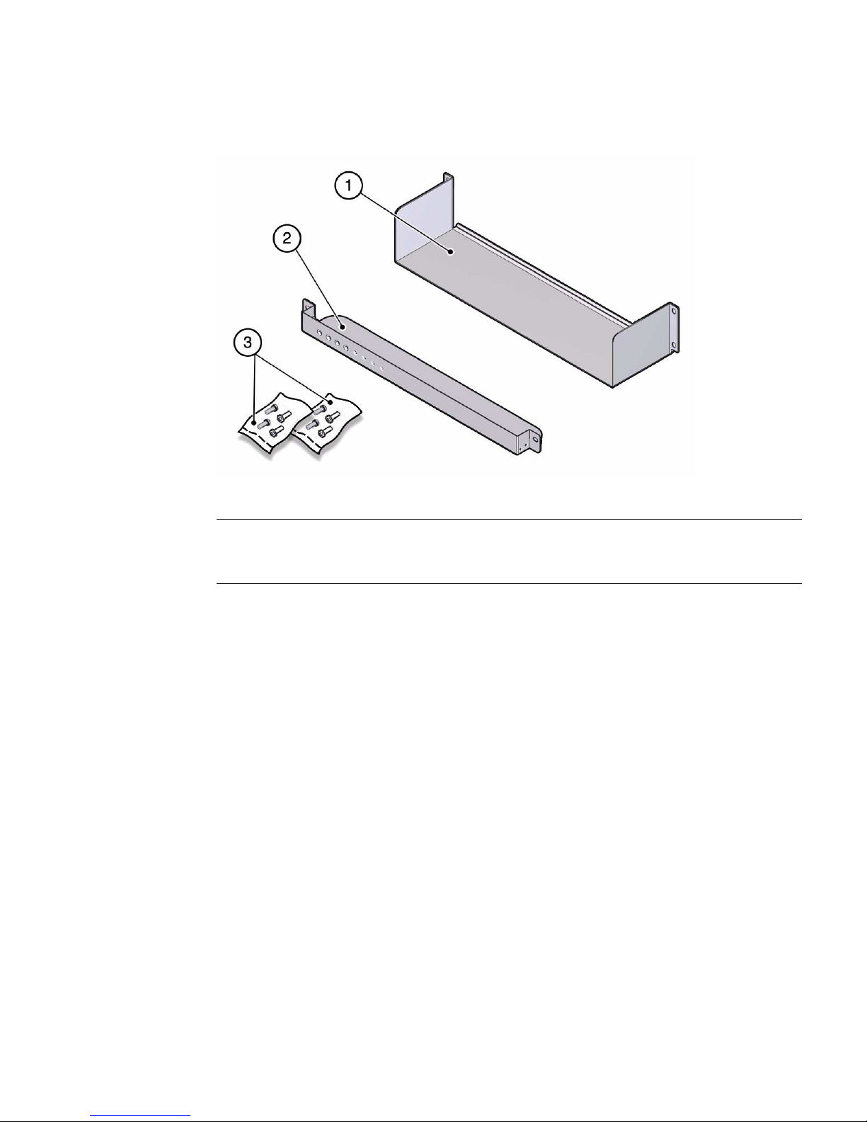
FIGURE: Shipping Bracket Kit
Figure Legend
1 Rear shipping bracket
2 Front shipping bracket
3 Fasteners
Related Information
■ “Tools Needed for Installation” on page 14
■ “Rack Compatibility” on page 16
■ “Determine Correct Rackmount Hardware” on page 19
■ “Mark the Rackmounting Location” on page 19
■ “Determine Correct Shipping Bracket Fasteners” on page 27
▼ Determine Correct Shipping Bracket Fasteners
● Use the following table to determine the correct fasteners for your shipping
bracket installation.
Installing the Server 27
Page 36

Cabinet Type Fastener Bags Required
Square hole with corner bezel SCREW, SEMS, M6 X 16MM
SCREW, SEMS, M6 X 30MM
Tapped hole (10-32) SCREW, SEMS, 10-32 X 1-1/4”
SCREW, SEMS, 10-32 X 10MM
Tapped hole (M6) SCREW, SEMS, M6 X 16MM
SCREW, SEMS, M6 X 30MM
Note – Some fastener bags are not required to install this server.
▼ Install the Front Shipping Bracket
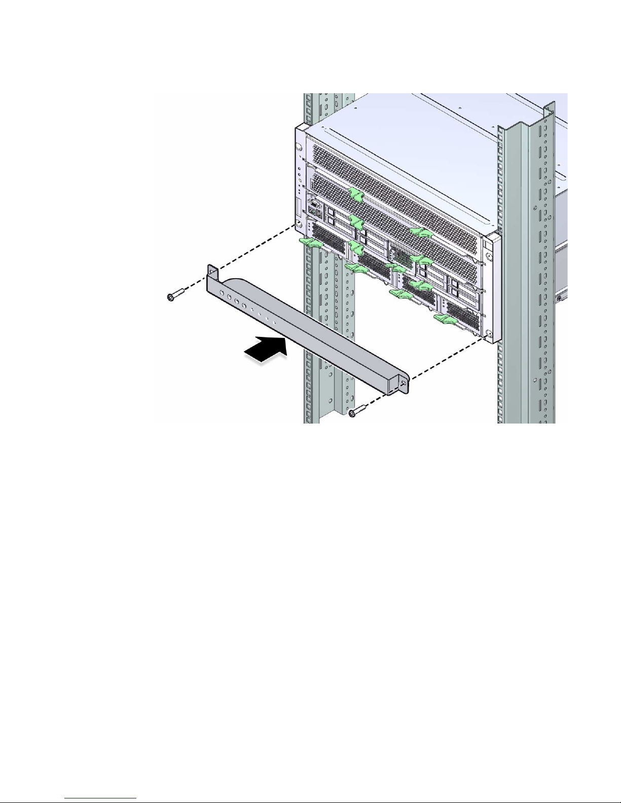
1. Remove the bottom two front panel mounting screws.
Note – Use the tapped holes in the front shipping bracket to secure these screws for
later use.
2. Hold the front shipping bracket in place.
3. Secure the front shipping bracket with two long screws.
28 SPARC T4-4 Server Installation Guide • May 2014
Page 37
▼ Install the Rear Shipping Bracket
1. Remove the bottom two rear rackmount screws on each side (four total).
The server is held in place by the four top screws (two on each side).
2. Hold the lower shipping bracket in place
3. Install two No. 2 Phillips screws in the bottom holes of the lower shipping
bracket.
Installing the Server 29
Page 38
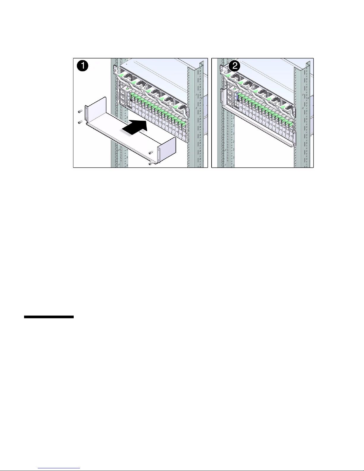
▼ Remove the Front Shipping Bracket
Remove the front shipping bracket after the server cabinet reaches its final
destination.
1. Remove the two short No. 2 Phillips screws that are stored with the shipping
bracket.
2. Remove the two screws that secure the front shipping bracket to the cabinet.
3. Slide the front shipping bracket out from the front of the cabinet.
4. Install the two short No. 2 Phillips screws into the lower two front panel screws.
Use the screws that were stored in the front shipping bracket during transit.
Installing the CMA (Optional)
The cable management assembly (CMA) is an optional kit for managing and routing
power and data cables attached to the back of the server.
This topic includes the following:
■ “CMA Kit” on page 31
■ “Determine Correct CMA Hardware” on page 31
■ “Install the CMA” on page 32
30 SPARC T4-4 Server Installation Guide • May 2014
Page 39
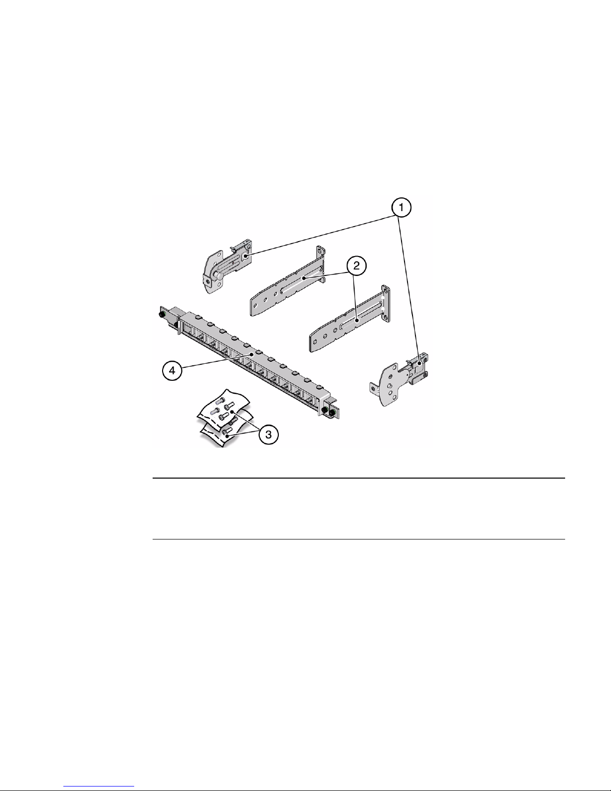
■ “Secure Cables Using the CMA” on page 42
CMA Kit
FIGURE: Cable Management Assembly (CMA)
Figure Legend
1 Swivel mounts
2 “L” brackets
3 Fastners
4 CMA
▼ Determine Correct CMA Hardware
● Use the following table to determine the hardware needed for your CMA
installation.
Installing the Server 31
Page 40

Cabinet Type Fastener Bags Required
Square hole
Round Hole (M6) (all types)
Round hole (10-32) (all types) SCREW, SEMS, 10-32 X 5/8”
SCREW, SEMS, M6 X 16MM
Note – Some of the fastener bags that are included in the kit are not required to
install this server.
▼ Install the CMA
The CMA is attached to the center rear of the server.
Note – The CMA installation might block some of the power outlets in the cabinet,
making them unavailable.
1. Install the L brackets at the rear . The brackets are marked “Left” and “Right” as
viewed from the back of the server.
Repeat for left and right sides:
a. Identify the “left” and “right” side brackets.
b. Remove the two middle screws from the rackmount adaptor.
c. Place the bracket over the center two mounting holes.
d. Secure each mounting bracket with two No. 2 Phillips screws.
32 SPARC T4-4 Server Installation Guide • May 2014
Page 41
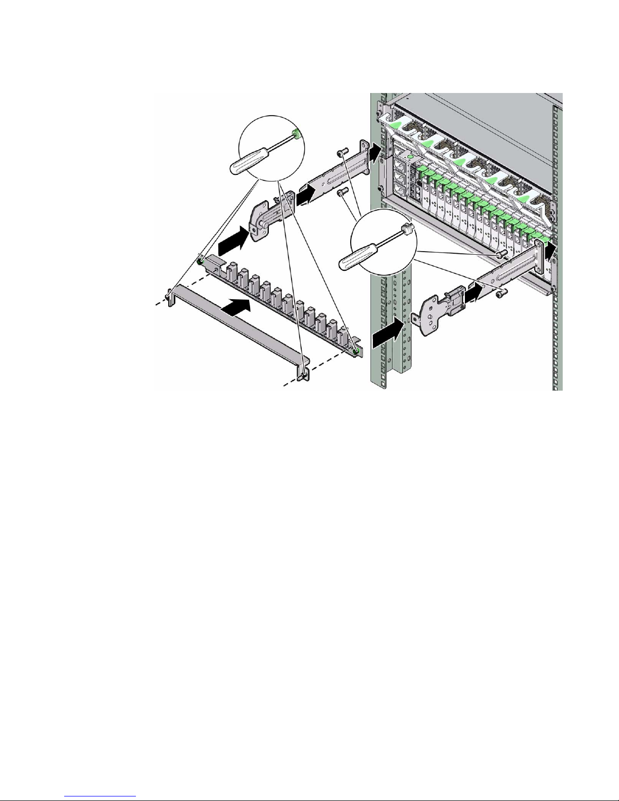
2. Slide the left and right swivel clips into the left and right L brackets.
3. Secure the CMA with the two captive screws.
Installing the Server 33
Page 42

34 SPARC T4-4 Server Installation Guide • May 2014
Page 43

Connecting the Server Cables
This topic describes how to connect cables to the server.
Step Description Links
1 Review the cabling requirements. “Cabling Requirements” on page 35
2 Review the front and rear panel connectors
and ports.
“Front Panel Components” on page 3
“Rear Panel Components” on page 4
“Identifying Ports” on page 37
3 Connect management and data cables. “Connecting Data and Management Cables”
on page 40
4 Secure cables with the CMA. “Secure Cables Using the CMA” on page 42
Related Information
■ “Confirming Server and Site Specifications” on page 1
■ “Installing the Server” on page 15
■ “Powering On the Server for the First Time” on page 45
Cabling Requirements
■ Minimum cable connections for the server:
■ At least one server on-board Ethernet network connection (NET port)
■ The service processor serial management port (SER MGT port)
■ The service processor network management port (NET MGT port)
■ Power cables for the server power supplies
■ Service processor management ports: There are two service processor
management ports for use with the ILOM service processor.
35
Page 44

■ The service processor serial management port (labeled SER MGT) uses an RJ-45
cable and is always available. This port is the default connection to the ILOM
service processor.
■ The service processor network management port (labeled NET MGT) is the
optional connection to the ILOM service processor. The NET MGT port is
configured to use DHCP by default. To set a static IP address, see “Assigning a
Static IP Address to the SP” on page 50. The service processor network
management port uses an RJ-45 cable for a 10/100 BASE-T connection. This
port does not support connections to Gigabit networks.
■ Ethernet ports are labeled NET0, NET1, NET2, and NET3. The Ethernet interfaces
operate at 10 Mbps, 100 Mbps, and 1000 Mbps.
Connection Type IEEE Terminology Transfer Rate
Ethernet 10BASE-T 10 Mbit/sec
Fast Ethernet 100BASE-TX 100 Mbits/sec
Gigabit Ethernet 1000BASE-T 1000 Mbit/sec
■ USB Ports: USB ports support hot-plugging. You can connect and disconnect USB
cables and peripheral devices while the server is running, without affecting server
operations.
■ You can only perform USB hot-plug operations while the OS is running. USB
hot-plug operations are not supported when the server ok prompt is displayed
or before the server has completed booting.
■ You can connect up to 126 devices to each of the four USB controllers, for a total
of 504 USB devices per server.
■ AC power cables: Do not attach power cables to the power supplies until you have
finished connecting the data cables, and have connected the server to a serial
terminal or a terminal emulator (PC or workstation). The server goes into Standby
mode and the ILOM service processor initializes as soon as the AC power cables
are connected to the power source. System messages might be lost after 60 seconds
if the server is not connected to a terminal, PC, or workstation.
Related Information
■ “Confirming Specifications” on page 5
■ “Handling Precautions” on page 13
■ “Rear Panel Cable Connections Reference” on page 24
36 SPARC T4-4 Server Installation Guide • May 2014
Page 45

Identifying Ports
■ “USB Ports” on page 37
■ “SER MGT Ports” on page 38
■ “NET MGT Port” on page 38
■ “Gigabit-Ethernet Ports” on page 39
■ “QSFP Port” on page 39
■ “VGA Port” on page 40
USB Ports
Two Universal Serial Bus (USB) ports are located the back panel.
Two additional USB ports are located on the main module, and are accessible from
the front panel.
Each USB port supplies 5V output at 500 mA.
2
1
4
3
B
2
1
4
3
A
Pin Signal Description Pin Signal Description
A1 +5 V (fused) B1 +5 V (fused)
A2 USB0/1- B2 USB2/3-
A3 USB0/1+ B3 USB2/3+
A4 Ground B4 Ground
Connecting the Server Cables 37
Page 46
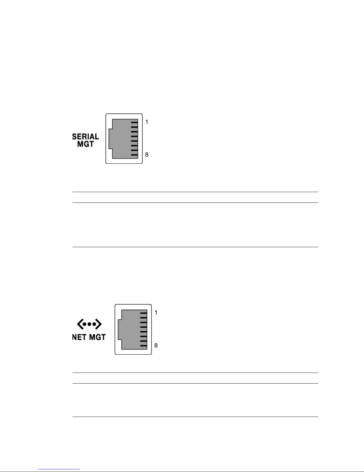
SER MGT Ports
The SER MGT port is an RJ-45 connector. There is one SER MGT port on the the back
panel. This port is the default connection to the system console.
An additional SER MGT port is located on the main module, and is accessible from
the front panel.
TABLE: Serial Management Connector Signals
Pin Signal Description Pin Signal Description
1 Request to Send 5 Ground
2 Data Terminal Ready 6 Receive Data
3 Transmit Data 7 Data Set Ready
4 Ground 8 Clear to Send
NET MGT Port
The NET MGT port is an RJ-45 connector located on the system back panel. This port
must be configured prior to use.
Pin Signal Description Pin Signal Description
1 Transmit Data + 5 Common Mode Termination
2 Transmit Data – 6 Receive Data –
3 Receive Data + 7 Common Mode Termination
38 SPARC T4-4 Server Installation Guide • May 2014
Page 47
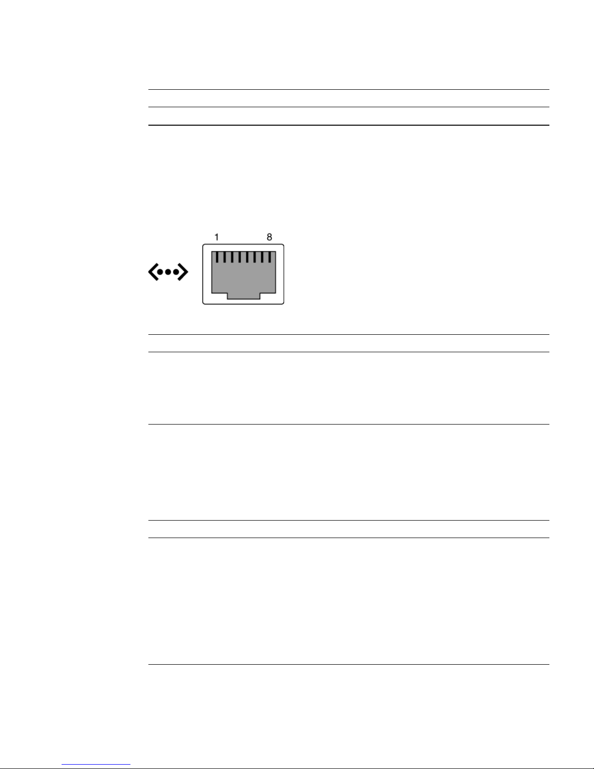
Pin Signal Description Pin Signal Description
4 Common Mode Termination 8 Common Mode Termination
Gigabit-Ethernet Ports
Four RJ-45 Gigabit Ethernet connectors (NET0, NET1, NET2, NET3) are located on
the system back panel. The Ethernet interfaces operate at 10 Mbit/sec, 100 Mbit/sec,
and 1000 Mbit/sec.
Pin Signal Description Pin Signal Description
1 Transmit/Receive Data 0 + 5 Transmit/Receive Data 2 –
2 Transmit/Receive Data 0 – 6 Transmit/Receive Data 1 –
3 Transmit/Receive Data 1 + 7 Transmit/Receive Data 3 +
4 Transmit/Receive Data 2 + 8 Transmit/Receive Data 3 –
QSFP Port
The QSFP connector is a 10-Gigabit XUAI port connection.
Pin Signal Pin Signal Pin Signal Pin Signal
1 GND 11 SCL 21 RX2n 31 Reserved
2 TX2n 12 SDA 22 RX2p 32 GND
3 TX2p 13 GND 23 GND 33 TX3p
4 GND 14 RX3p 24 RX4n 34 TX3n
5 TX4n 15 RX3n 25 RX4p 35 GND
6 TX4p 16 GND 26 GND 36 TX1p
7 GND 17 RX1p 27 ModPrsL 37 TX1n
Connecting the Server Cables 39
Page 48

Pin Signal Pin Signal Pin Signal Pin Signal
8 ModSeIL 18 RX1n 28 IntL 38 GND
9 LPMode_Reset 19 GND 29 VccTx
10 VccRx 20 GND 30 Vcc1
VGA Port
One VGA port is located on the front panel.
Pin Signal Description Pin Signal Description
1 Red Video 9 [KEY]
2 Green Video 10 Sync Ground
3 Blue Video 11 Monitor ID - Bit 1
4 Monitor ID - Bit 2 12 Monitor ID - Bit 0
5 Ground 13 Horizontal Sync
6 Red Ground 14 Vertical Sync
7 Green Ground 15 N/C (Reserved)
8 Blue Ground
Connecting Data and Management
Cables
Caution – Finish the hardware procedures in this chapter, but do not attach the AC
power cables to a power source yet.
■ “Connect the SER MGT Cable” on page 41
■ “Connect the NET MGT Cable” on page 41
■ “Connect the Ethernet Network Cables” on page 42
■ “Connect Other Data Cables” on page 42
40 SPARC T4-4 Server Installation Guide • May 2014
Page 49

▼ Connect the SER MGT Cable
The service processor serial management port is marked SER MGT. See “Front Panel
Components” on page 3 and “Rear Panel Components” on page 4 for connector
locations.
● Connect a Category 5 cable from the service processor SER MGT port to the
terminal device.
Use this port for initial server management. This port is needed to activate the
NET MGT port, as detailed in “Powering On the Server for the First Time” on
page 45.
When connecting either a DB-9 or a DB-25 cable, use an adapter to perform the
crossovers given for each connector.
Note – Use the service processor serial management port only for server
management. It is the default connection between the service processor and a
terminal or a computer.
Caution – Do not attach a modem to the service processor serial management port.
▼ Connect the NET MGT Cable
● Connect a Category 5 cable from the service processor network management
port to your network switch or hub. See “Rear Panel Components” on page 4 for
connector locations.
The service processor network management port is labeled NET MGT. This port is
not operational until you configure the network settings (through the serial
management port), as detailed in “Log In to the SP (SER MGT Port)” on page 51.
If you have access to a DHCP server on the network, you can see the service
processor get an IP address because the DHCP client is enabled by default.
Note – The NET MGT port is configured by default to retrieve network settings with
DHCP and allow connections using SSH. You might need to modify these settings for
your network. Instructions are given in “Powering On the Server for the First Time”
on page 45.
Connecting the Server Cables 41
Page 50

▼ Connect the Ethernet Network Cables
The server has four network connectors, marked NET0, NET1, NET2, and NET3.
These connectors are RJ-45 Gigabit Ethernet. See “Rear Panel Components” on page 4
for connector locations.
Note – The ILOM sideband management feature enables you to access the SP using
one of these Ethernet ports. Refer to the SPARC T3 Series Servers Administration Guide
for instructions.
1. Connect a Category 5 (or better) cable from your network switch or hub to
Ethernet Port 0 (NET0) on the rear of the chassis.
2. Connect Category 5 (or better) cables from your network switch or hub to the
remaining Ethernet ports (NET1, NET2, NET3), as needed.
▼ Connect Other Data Cables
● If the server is configured with additional I/O components, connect the external
cables to the server.
See peripheral documentation for specific instructions.
▼ Secure Cables Using the CMA
Use the CMA to secure cables and ensure proper cable routing.
1. Remove the CMA cover.
The CMA cover is secured with two No. 2 Phillips screws.
42 SPARC T4-4 Server Installation Guide • May 2014
Page 51
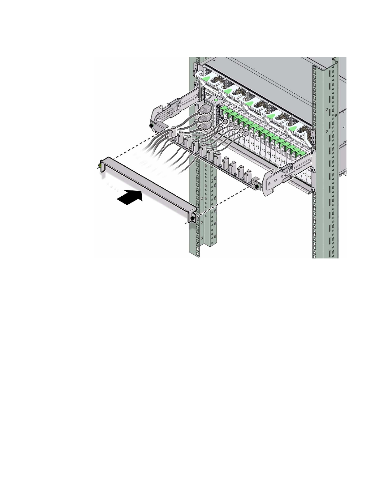
2. Place system cables into appropriate slots in the CMA.
See “Connecting the Server Cables” on page 35.
3. Install the CMA cover.
The cover is secured with two No. 2 Phillips screws.
Connecting the Server Cables 43
Page 52

44 SPARC T4-4 Server Installation Guide • May 2014
Page 53

Powering On the Server for the First
Time
These topics include instructions for booting the server and for enabling the service
processor network management port.
Step Description Links
1 Connect a serial terminal device or
terminal server to the SER MGT port.
2 Prepare the power cords. “Prepare Power Cords” on page 46
3 Power on the server for the first time. “Power On the System for the First Time” on
4 Set Oracle Solaris OS configuration
parameters.
5 (Optional) Configure the NET MGT port to use a
static IP address.
6 Boot the Oracle Solaris OS. “Booting the Oracle Solaris Operating System”
“Connect a Terminal or Emulator to the SER
MGT Port” on page 46
page 47
“Oracle Solaris OS Configuration Parameters”
on page 49
“Assigning a Static IP Address to the SP” on
page 50
on page 55
Related Information
■ “Confirming Server and Site Specifications” on page 1
■ “Installing the SPARC T3-4 Server” on page 13
■ “Connecting the Server Cables” on page 35
45
Page 54

▼ Connect a Terminal or Emulator to the
SER MGT Port
● Connect a terminal or a terminal emulator (PC or workstation) to the service
processor serial management port.
Configure the terminal or terminal emulator with these settings:
■ 9600 baud
■ 8 bits
■ No parity
■ 1 Stop bit
■ No handshake
A null modem configuration is needed, meaning the transmit and receive signals
are reversed (crossed over) for DTE to DTE communications. You can use the
supplied RJ-45 crossover adapters with a standard RJ-45 cable to achieve the null
modem configuration.
Note – When you power on the server for the first time and you do not have a
terminal or terminal emulator (PC or workstation) connected to the service processor
serial management port, you will not see system messages.
▼ Prepare Power Cords
Powering on the server for the first time requires special preparation and
procedures. For example, if you have not prepared a display before connecting the
AC power cable, initial system messages could be lost.
Caution – The server goes into Standby mode and the service processor initializes
as soon as the AC power cable is connected to the power source.
● Go to “Power On the System for the First Time” on page 47 for instructions on
connecting the server to AC power.
46 SPARC T4-4 Server Installation Guide • May 2014
Page 55

▼ Power On the System for the First
Time
Complete the following tasks:
■ Confirm that you have completed the installation of the server in its rack. See
“Installing the Server” on page 15.
■ Attach the cable management assembly. See “Install the CMA” on page 32.
■ Connect a terminal or terminal emulator to the SER MGT port. See “Connect a
Terminal or Emulator to the SER MGT Port” on page 46.
1. (Optional) Connect an Ethernet cable between the server’s NET MGT port and
the network to which future connections to the SP and host will be made. See
“Connect the NET MGT Cable” on page 41.
After the initial configuration of the server using the SER MGT port,
communication with the SP and host is usually performed through this Ethernet
interface.
2. Connect an Ethernet cable between one of the server’s NET ports (“Rear Panel
Components” on page 4) and the network to which the server will communicate.
3. Plug the power cords into the power supplies and into a power source.
Note – Only two power connections are required for operation. Use four power
connections and two separate circuits for redundancy.
The service processor runs on the 3.3V standby voltage. As soon as AC power is
connected to the server, the service processor powers on, runs diagnostics, and
initializes the ILOM firmware.
After a few minutes, the SP login prompt appears on the terminal device. The host
is not initialized or powered on yet.
4. At the terminal device, log in to the SP as root with a password of changeme.
XXXXXXXXXXXXXXXX login: root
Password: changeme
. . .
->
After a brief delay, the Oracle ILOM prompt is displayed (->).
Powering On the Server for the First Time 47
Page 56

Note – To enable first-time login and access to Oracle ILOM, a default Administrator
account and its password are provided with the system. To build a secure
environment, you must change the default password (changeme) for the default
Administrator account (root) after your initial login to Oracle ILOM. If this default
Administrator account has been changed, contact your system administrator for an
Oracle ILOM user account with Administrator privileges.
For more information about the administration tasks such as changing passwords,
adding accounts, and setting account privileges, refer to the Oracle ILOM
documentation.
Note – By default, the SP is configured to use DHCP to obtain an IP address. If you
plan to assign a static IP address to the SP, see“Assign a Static IP Address to the NET
MGT Port” on page 52 for more instructions.
5. Open a second terminal device and log in to the SP as root.
After a brief delay, the SP prompt is displayed (->). At this point, there are many
commands you can perform using the ILOM interface.
6. In the first terminal device, redirect the host output to display on the serial
terminal device:
-> start /SP/console
Are you sure you want to start /SP/console (y/n)? y
Serial console started. To stop, type #.
. . .
After you start the SP console, the server initialization takes approximately 20
minutes to complete. This terminal device displays all SP console messages during
intial boot.
7. In the second terminal device, power on the server:
-> start /SYS
Are you sure you want to start /SYS (y/n)? y
This terminal device displays all system console messages during initial boot.
8. When prompted, follow the onscreen instructions for configuring the Oracle
Solaris Operating System on your host and enter the following configuration
information.
You will be prompted to confirm the configuration several times, enabling
confirmation and changes. If you are not sure how to respond to a particular
value, you can accept the default, and make future changes when the Oracle
48 SPARC T4-4 Server Installation Guide • May 2014
Page 57

Solaris OS is running. See “Oracle Solaris OS Configuration Parameters” on
page 49 for a description of the Oracle Solaris OS parameters you must provide
during initial configuration.
9. Log in to the server and explore its capabilities.
There are many commands you can use to verify the functionality of the server.
The following list describes a few of them:
■ showrev – Displays the host name and server architecture information. Use the
-a option with this command to see the patches that are installed.
■ psrinfo – Displays information about the number and status of the processors
and cores in the host.
■ prtdiag – Displays server configuration and diagnostic information.
Review the Oracle Solaris OS man pages and documentation for more details.
Oracle Solaris OS Configuration
Parameters
This topic describes configuration parameters you must provide during initial Oracle
Solaris OS configuration.
Parameter Description
Language Select a number from the displayed language list.
Locale Select a number from the displayed locale list.
Terminal Type Select a terminal type that corresponds with your terminal device.
Network? Select Yes.
Multiple Network
Interfaces
DHCP? Select Yes or No according to your network environment.
Host Name Type the host name for the server.
IP Address Type the IP address for this Ethernet interface.
Subnet? Select Yes or No according to your network environment.
Subnet Netmask (If subnet was Yes) Type the netmask for the subnet for your network environment.
Select the network interfaces that you plan to configure. If you are not sure, select
the first one in the list.
Powering On the Server for the First Time 49
Page 58

IPv6? Specify whether or not to use IPv6. If you are not sure, select No to configure the
Ethernet interface for IPv4.
Security Policy Select either standard UNIX security (No) or Kerberos Security (Yes). If you are not
sure, select No.
Confirm Review the onscreen information and change it if needed. Otherwise, continue.
Name Service Select the name service according to your network environment.
Note–If you select a name service other than None, you will be prompted for
additional name service configuration information.
NFSv4 Domain Name Select the type of domain name configuration according to your environment. If
you are not sure, select Use the NFSv4 domain derived by the server.
Time Zone (Continent) Select your continent.
Time Zone (Country or
Select your country or region.
Region)
Time Zone Select the time zone.
Date and Time Accept the default date and time or change the values.
root Password Type the root password twice. This password is for the superuser account for the
Oracle Solaris OS on this server. This password is not the SP password.
Related Information
■ “Rear Panel Cable Connections Reference” on page 24
■ “Assigning a Static IP Address to the SP” on page 50
■ “Boot the Oracle Solaris Operating System” on page 56
■ “Booting the Oracle Solaris Operating System” on page 55
Assigning a Static IP Address to the SP
If your network does not use DHCP, the network management port is not operational
until you configure network settings for the service processor.
This topic includes the following tasks:
■ “Oracle ILOM System Console Overview” on page 51
■ “Log In to the SP (SER MGT Port)” on page 51
■ “Assign a Static IP Address to the NET MGT Port” on page 52
50 SPARC T4-4 Server Installation Guide • May 2014
Page 59

Related Information
■ “Oracle ILOM System Console Overview” on page 51
■ “Oracle Solaris OS Configuration Parameters” on page 49
Oracle ILOM System Console Overview
When you power on the server, the boot process begins under the control of the
Oracle Integrated Lights Out Manager system console. The ILOM system console
displays status and error messages generated by firmware-based tests during server
startup.
By default, ILOM system console messages are directed to the NET MGT port. The
NET MGT port uses DHCP and allows connections using SSH.
Note – If you are unable to use DHCP on your network, you must connect to the
ILOM service processor using the serial management port to configure the network
management port for your network. See “Assign a Static IP Address to the NET MGT
Port” on page 52.
Related Information
■ “Assigning a Static IP Address to the SP” on page 50
▼ Log In to the SP (SER MGT Port)
After the service processor boots, access the ILOM CLI to configure and manage the
server. The ILOM CLI prompt (->) is displayed at the first time the service processor
is booted. The default configuration provides an ILOM CLI root user account. The
default root password is changeme. Change the password using the service processor
ILOM CLI password command.
1. If this is the first time the server has been powered on, use the password
command to change the root password.
...
Starting OpenBSD Secure Shell server: sshd.
Starting Servicetags listener: stlistener.
Starting FRU update program: frutool.
hostname login: root
Password: changeme
Powering On the Server for the First Time 51
Page 60

Copyright 2007 Sun Microsystems, Inc. All rights reserved.
Use is subject to license terms.
...
Federal Acquisitions: Commercial Software -- Government Users
Subject to Standard License Terms and Conditions.
...
Warning: password is set to factory default.
-> set /HOST/users/root password
Enter new password: ********
Enter new password again: ********
->
Note – After the root password has been set, on subsequent reboots, the ILOM CLI
login prompt is displayed.
2. Enter root for the login name followed by your password.
...
hostname login: root
Password: password (nothing displayed)
Waiting for daemons to initialize...
Daemons ready
Integrated Lights Out Manager
Version 2.0.0.0
Copyright 2007 Sun Microsystems, Inc. All rights reserved.
Use is subject to license terms.
->
▼ Assign a Static IP Address to the NET MGT Port
Use this procedure only when:
■ You are unable to use DHCP on your network.
■ You need to modify the NET MGT port settings.
52 SPARC T4-4 Server Installation Guide • May 2014
Page 61

In this procedure, you connect to the SER MGT port to manually reconfigure the NET
MGT port to use a static IP address.
Note – For more information on configuring ILOM, refer to the SPARC T4-4 Server
Installation Guide.
1. Set these network parameters according to the specific details of your network
configuration.
Parameter Description
/SP/network state Specifies whether or not the service processor
is on the network.
/SP/network pendingipaddress IP address of the service processor.
/SP/network pendingipgateway IP address of the gateway for the subnet.
/SP/network pendingipnetmask Netmask for the service processor subnet.
/SP/network pindingipdiscovery Specifies whether the service processor uses
DHCP or static IP address assignment.
/SP/network commitpending Commits the service processor to use the
pending settings
Configure these parameters using the set command. For example:
-> set /host/network pendingaddress=xxx.xxx.xxx.xxx
Set ‘pendingaddress’ to ‘xxx.xxx.xxx.xxx’
2. Configure the service processor using information from your network
administrator.
Parameter Description
dhcp Set up the network connection with a dynamically created IP
configuration.
static Set up the network connection with a static IP configuration.
a. If you choose to use a dynamically created IP address (use DHCP to retrieve
the network setting), set pendingipdiscovery to dhcp.
-> set /SP/network pendingipdiscovery=dhcp
Set 'pendingipdiscovery' to 'dhcp'
Powering On the Server for the First Time 53
Page 62

b. If you choose to configure a static IP configuration. set the parameters
pendingipdiscovery, pendingipaddress, pendingipgateway, and
pendingipnetmask as follows.
i. Set the service processor to accept a static IP address.
-> set /SP/network pendingipdiscovery=static
Set 'pendingipdiscovery' to 'static'
ii. Set the IP address for the service processor.
-> set /SP/network pendingipaddress=service-processor-IPaddr
Set 'pendingipaddress' to 'service-processor-IPaddr'
iii. Set the IP address for the service processor gateway.
-> set /SP/network pendingipgateway=gateway-IPaddr
Set 'pendingipgateway' to 'gateway-IPaddr'
iv. Set the netmask for the service processor.
-> set /SP/network pendingipnetmask=255.255.255.0
Set 'pendingipnetmask' to '255.255.255.0'
This example uses 255.255.255.0 to set the netmask. Your network
environment subnet might require a different netmask. Use a netmask
number most appropriate to your environment.
3. Use the show /SP/network command to verify that the parameters were set
correctly.
The following example shows parameters that have been set to convert a service
processor from a DHCP configuration to a static configuration.
-> show /SP/network
/SP/network
Targets:
Properties:
commitpending = (Cannot show property)
dhcp_server_ip = xxx.xxx.xxx.xxx
ipaddress = xxx.xxx.xxx.xxx
ipdiscovery = dhcp
ipgateway = xxx.xxx.xxx.xxx
ipnetmask = 255.255.252.0
macaddress = 00:14:4F:3F:8C:AF
pendingipaddress = xxx.xxx.xxx.xxx
54 SPARC T4-4 Server Installation Guide • May 2014
Page 63

pendingipdiscovery = static
pendingipgateway = xxx.xxx.xxx.xxx
pendingipnetmask = 255.255.255.0
state = enabled
Commands:
cd
set
show
->
Note – After setting the configuration parameters, you must enter the set
/SP/network commitpending=true command for the new values to take affect.
4. Commit the changes to the service processor network parameters.
-> set /SP/network commitpending=true
Set 'commitpending' to 'true'
Note – You can run the show /SP/network command again (after performing the
set /SP/network commitpending=true command) to verify that the
parameters have been updated.
Booting the Oracle Solaris Operating
System
The Oracle Solaris OS is preinstalled on the server on the disk in slot 0. The Oracle
Solaris OS is not configured (that is, the sys-unconfig command was run in the
factory). If you boot the server from this disk, you will be prompted to configure the
Oracle Solaris OS for your environment.
After powering on the server for the first time, you can use Oracle VTS software to
verify the functionality and performance of any installed components, as well as its
network connections. For more information, refer to the Oracle VTS documentation
at:
http://www.oracle.com/pls/topic/lookup?ctx=OracleVTS7.0
For more information about configuring the server and using the ILOM service
processor, refer to the SPARC T4-4 Server Installation Guide.
Powering On the Server for the First Time 55
Page 64

For more information about adding optional components, refer to the SPARC T4-4
Server Service Manual.
These topics describe the following tasks:
■ “Boot the Oracle Solaris Operating System” on page 56
■ “Avoid Booting the Oracle Solaris Operating System at Start Up” on page 57
■ “Reset the Server” on page 57
■ “Power Cycle the Server” on page 57
Related Information
■ “Oracle Solaris OS Configuration Parameters” on page 49
■ Oracle VTS documentation
▼ Boot the Oracle Solaris Operating System
1. At the ok prompt, boot from the disk that contains the Oracle Solaris OS.
■ If you know which disk to boot from, skip this step and perform Step 2.
■ If you need to determine which disk to boot from, type the show-disks
command at the ok prompt to see the path to the configured disks, similar to
the following:
ok show-disks
a) /pci@0/pci@0/pci@2/scsi@0/disk0
b) /pci@0/pci@0/pci@1/pci@0/pci@1/pci@0/usb@0,2/storage@2/disk
q) NO SELECTION Enter Selection, q to quit: q
ok
2. Type the boot command at the ok prompt.
Use the value from Step 1 to construct the boot command. You must append the
target to the disk path.
In the following example, the server is booted from disk 0 (zero).
ok boot disk0
Boot device: /pci@0/pci@0/pci@2/scsi@0/disk@0 File and args:
SunOS Release 5.10 Version Generic_127127-03 64-bit
Copyright 1983-2010 Oracle Corp. All rights reserved.
Use is subject to license terms.
Hostname: hostname
NIS domain name is x.x.x.x
56 SPARC T4-4 Server Installation Guide • May 2014
Page 65

hostname console login:
▼ Avoid Booting the Oracle Solaris Operating
System at Start Up
In hard drive HDD0, the Oracle Solaris OS is preinstalled.
● If you do not want to start the preinstalled OS, set the Open Boot PROM
parameter auto-boot? to false. For example:
-> set /HOST/bootmode script="setenv auto-boot? false"
▼ Reset the Server
● If it is necessary to reset the server, use the shutdown -g0 -i6 -y command.
# shutdown -g0 -i6 -y
It is not necessary to power the server off and on to simply reset the server.
▼ Power Cycle the Server
If a simple reset does not clear a system problem, you can power the server off and
on with this procedure.
1. Shut down the Oracle Solaris OS.
At the Oracle Solaris OS prompt, type the shutdown -g0 -i0 -y command.
Then type h when prompted to halt the Oracle Solaris OS and to return to the ok
prompt.
# shutdown -g0 -i0 -y
# svc.startd: The system is coming down. Please wait.
svc.startd: 91 system services are now being stopped.
Jun 12 19:46:57 wgs40-58 syslogd: going down on signal 15
svc.startd: The system is down.
syncing file systems... done
Program terminated
r)eboot, o)k prompt, h)alt?
Powering On the Server for the First Time 57
Page 66

2. Switch from the system console prompt to the service processor console prompt
by issuing the console escape sequence (by default, #.).
ok #.
->
3. Using the ILOM CLI, type the stop /SYS command to perform a graceful
shutdown of the server.
-> stop /SYS
Are you sure you want to stop /SYS (y/n)? y
Stopping /SYS
->
Note – To perform an immediate and ungraceful shutdown, use the stop -force
-script /SYS or stop -script /SYS commands. These commands stop
everything immediately. Ensure that all data is saved before entering these
commands.
4. Type the start /SYS command.
-> start /SYS
Are you sure you want to start /SYS (y/n)? y
Starting /SYS
->
Note – To force a power-on sequence, use the start -script /SYS command.
5. Reconnect to the system console with the start /HOST/console command.
-> start /HOST/console
Are you sure you want to start /HOST/console (y/n)? y
Serial console started. To stop, type #.
The system console displays various messages, followed by the ok prompt.
58 SPARC T4-4 Server Installation Guide • May 2014
Page 67

Index
Symbols
#. escape sequence for system console, 58
A
acoustic noise emissions, 9
adapters for serial cables, 41
admin login, setting password for, 51
B
baud rate for serial terminal, 46
bits setting for serial terminal, 46
boot
booting the system, 45
OpenBoot PROM boot command, 56
C
cables
adapters for serial data cables, 41
CMA fasteners, 31
command
set /SP/network,54
show /SP/network,54
show-disks,56
compatible racks, 16
connectors
front panel, 3
rear panel, 4
console command, 58
D
diagnostics, when run, 47
E
escape sequence #. for system console, 58
F
fasteners
CMA, 31
rackmount kit, 19
shipping bracket, 27
front panel connectors, 3
full disk path example, 56
G
Gigabit Ethernet port pinouts, 39
H
handshaking for serial terminal, no, 46
hot-plugging USB ports, 36
L
LEDs, ports, and slots illustrated, 4
locations of ports, slots, and LEDs (illustration), 4
logging into service processor
using serial management port, 51
M
messages retention, limits of, 36
minimum cable connections, 35
modem not for use with the SER MGT serial
management port, 41
N
NET MGT port pinouts, 38
O
Oracle Solaris OS
avoid booting into at startup, 57
booting into, 56
59
Page 68

P
parity for serial terminal, no, 46
password command, 51
pinouts
Gigabit Ethernet ports, 39
NET MGT port, 38
QSFP connector, 39
USB ports, 37
ports, slots, and LEDs illustrated, 4
power cycling the system, 57
poweroff command, 58
Q
QSFP connector pinouts, 39
R
rackmount fasteners, 19
rackmount kit contents, 17
rackmounting, 15
racks, compatible, 16
rear panel connectors, 4
reset
resetting the system with uadmin,57
RJ-45 cable, 36
Standby mode, 46
standby mode, when AC connected, 36
standby voltage, 3.3v, 47
stop bit, 46
system console escape sequence #.,58
system reset, 57
T
terms
slide rail assembly, 17
U
uadmin command, 57
USB port
output power, 37
USB port pinouts, 37
S
serial management port, 51
serial terminal
settings, 46
service processor
accessing with serial management port, 51
log in using serial management port, 51
powering on for the first time, 47
set command, 53
set command, 53
shipping bracket
front, installation, 28
front, removal at destination, 30
kit contents, 26
rear, installation, 29
shipping bracket fasteners, 27
shipping kit contents, 11
show /SP/network command, 54
show-disks command, 56
slots, ports, and LEDs illustrated, 4
60 SPARC T4-4 Server Installation Guide • May 2014
 Loading...