


SPARC T4-1 Server
Installation Guide
Part No.: E22988-09
August 2013

Copyright ©2011, 2013, Oracle and/or its affiliates. Allrights reserved.
This softwareand related documentation are provided undera license agreement containing restrictions on use and disclosureand are protected by
intellectual propertylaws. Exceptas expressly permitted inyour licenseagreement or allowed by law, you may not use, copy, reproduce, translate,
broadcast, modify, license, transmit, distribute, exhibit, perform, publish, or display any part, in any form, or by any means. Reverse engineering,
disassembly, or decompilation of this software, unless requiredby lawfor interoperability, is prohibited.
The informationcontained hereinis subjectto changewithout noticeand isnot warrantedto beerror-free.If youfind anyerrors, please report them to us
in writing.
If thisis softwareor related software documentation that is delivered to the U.S. Government or anyone licensing it on behalf of the U.S. Government, the
following noticeis applicable:
U.S. GOVERNMENTEND USERS.Oracle programs,including anyoperating system,integrated software, any programs installed onthe hardware,
and/or documentation,delivered toU.S. Governmentend usersare "commercial computer software" pursuantto theapplicable FederalAcquisition
Regulation andagency-specific supplementalregulations. Assuch, use,duplication, disclosure, modification, andadaptation ofthe programs, including
any operatingsystem, integratedsoftware, anyprograms installed on the hardware,and/or documentation,shall besubject tolicense termsand license
restrictions applicableto theprograms. No other rights are granted to the U.S. Government.
This software or hardware is developed for general use in a variety ofinformation managementapplications. It is not developed or intended for usein any
inherently dangerous applications, includingapplications thatmay create a riskof personalinjury. If you use this software or hardwarein dangerous
applications, thenyou shallbe responsibleto takeall appropriate fail-safe, backup,redundancy, and other measuresto ensure its safeuse. Oracle
Corporation andits affiliatesdisclaim anyliability forany damagescaused byuse ofthis software or hardware in dangerous applications.
Oracle andJava areregistered trademarks of Oracle and/or its affiliates.Other namesmay betrademarks oftheir respective owners.
Intel andIntel Xeonare trademarksor registered trademarks of Intel Corporation. All SPARC trademarks areused underlicense andare trademarks or
registered trademarks of SPARCInternational, Inc. AMD, Opteron, theAMD logo,and theAMD Opteron logo are trademarksor registered trademarksof
Advanced MicroDevices. UNIXis aregistered trademark of The Open Group.
This software or hardware and documentation may provide access to or information on content, products, and services from third parties. Oracle
Corporation and its affiliates are not responsible for and expressly disclaim all warranties of any kind with respect to third-party content, products, and
services. Oracle Corporation and its affiliates will not be responsible for any loss, costs, or damages incurred due to your access to or use of third-party
content, products, or services.
Copyright ©2011, 2013, Oracle et/ou ses affiliés. Tous droits réservés.
Ce logicielet ladocumentation quil’accompagne sontprotégés parles loissur lapropriété intellectuelle. Ils sont concédés sous licence et soumis à des
restrictions d’utilisationet dedivulgation. Saufdisposition devotre contrat de licence ou de la loi, vous ne pouvez pas copier, reproduire,traduire,
diffuser, modifier,breveter, transmettre, distribuer, exposer,exécuter,publier ouafficher le logiciel, même partiellement, sous quelque forme et par
quelque procédéque cesoit. Parailleurs, ilest interdit de procéder à touteingénierie inversedu logiciel,de ledésassembler oude ledécompiler,excepté à
des finsd’interopérabilité avecdes logicielstiers outel queprescrit par la loi.
Les informationsfournies dansce documentsont susceptiblesde modificationsans préavis.Par ailleurs,Oracle Corporationne garantitpas qu’elles
soient exemptesd’erreurs etvous invite,le caséchéant, àlui enfaire part par écrit.
Si celogiciel, oula documentationqui l’accompagne,est concédésous licenceau Gouvernementdes Etats-Unis,ou àtoute entitéqui délivrela licencede
ce logicielou l’utilisepour lecompte duGouvernement desEtats-Unis, lanotice suivantes’applique :
U.S. GOVERNMENTEND USERS.Oracle programs,including anyoperating system,integrated software, any programs installed onthe hardware,
and/or documentation,delivered toU.S. Governmentend usersare "commercial computer software" pursuantto theapplicable FederalAcquisition
Regulation andagency-specific supplementalregulations. Assuch, use,duplication, disclosure, modification, andadaptation ofthe programs, including
any operatingsystem, integratedsoftware, anyprograms installed on the hardware,and/or documentation,shall besubject tolicense termsand license
restrictions applicableto theprograms. No other rights are granted to the U.S. Government.
Ce logicielou matériela étédéveloppé pourun usagegénéral dansle cadred’applications degestion desinformations. Celogiciel oumatériel n’estpas
conçu nin’est destinéà êtreutilisé dansdes applicationsà risque,notamment dansdes applicationspouvant causerdes dommagescorporels. Si vous
utilisez celogiciel oumatériel dansle cadred’applications dangereuses, il estde votre responsabilité de prendre toutes les mesures desecours, de
sauvegarde, deredondance et autres mesures nécessaires à sonutilisation dansdes conditionsoptimales desécurité. OracleCorporation etses affiliés
déclinent touteresponsabilité quantaux dommagescausés parl’utilisation dece logicielou matérielpour cetype d’applications.
Oracle etJava sontdes marquesdéposées d’OracleCorporation et/oude sesaffiliés.Tout autre nom mentionné peut correspondre à desmarques
appartenant àd’autres propriétaires qu’Oracle.
Intel etIntel Xeonsont desmarques oudes marques déposées d’IntelCorporation. Toutes lesmarques SPARCsont utiliséessous licenceet sontdes
marques oudes marques déposées deSPARC International, Inc.AMD, Opteron, le logoAMD etle logoAMD Opteron sont desmarques oudes marques
déposées d’AdvancedMicro Devices.UNIX estune marque déposée d’TheOpen Group.
Ce logicielou matérielet ladocumentation quil’accompagne peuventfournir desinformations oudes liensdonnant accèsà descontenus, desproduits et
des servicesémanant detiers. OracleCorporation etses affiliésdéclinent touteresponsabilité ou garantie expresse quant aux contenus, produits ou
services émanantde tiers.En aucuncas, OracleCorporation etses affiliésne sauraientêtre tenus pour responsables des pertes subies, des coûts
occasionnés oudes dommagescausés parl’accès àdes contenus,produits ouservices tiers,ou àleur utilisation.
Please
Recycle

Contents
Using This Documentation vii
Confirming Server and Site Specifications 1
Server Overview 1
Front Panel Components 3
Front Panel System LEDs and Buttons 4
Rear Panel Components 6
Rear Panel System LED and Button 7
Confirming Specifications 8
Physical Specifications 9
Minimum Clearance for Service Access 9
Electrical and Power Specifications 9
Environmental Specifications 11
Acoustic Noise Emissions 12
Airflow Considerations 12
Preparing for Installation 15
Shipping Kit Inventory List 15
Handling Precautions 17
ESD Precautions 17
Tools Needed for Installation 18
Installing the Server 19
iii

Rack Compatibility 19
▼ Stabilize the Rack 21
Installing Slide Rails 22
Slide Rail Assemblies 22
▼ Install the Slide Rail Assemblies 25
▼ Install the Server 29
(Optional) Installing the CMA 31
▼ Install the CMA 31
▼ Verify Correct Operation of the Slide Rails and the CMA 36
Connecting Cables 39
Cabling Requirements 39
Identifying Ports 40
USB Ports 41
SER MGT Port 41
NET MGT Port 42
Gigabit Ethernet Ports 43
Video Port 43
Connecting Data and Management Ports 44
▼ Connect the SER MGT Port Cable 44
▼ Connect the NET MGT Port Cable 45
▼ Connect the Ethernet Network Cables 46
▼ Connect Other Data Cables 47
▼ Secure Cables in the CMA 48
Powering On the Server for the First Time 51
Oracle ILOM System Console 51
▼ Connect a Terminal or Emulator to the SER MGT Port 52
▼ Power On the Server for the First Time 53
iv SPARC T4-1 Server Installation Guide • August 2013

▼ Verify Functionality 55
Assigning a Static IP Address to the SP 55
▼ Assign a Static IP Address to the SP 55
Oracle Solaris OS Configuration Parameters 57
Glossary 59
Index 65
Contents v

vi SPARC T4-1 Server Installation Guide • August 2013

Using This Documentation
This installation guide provides instructions, background information, and reference
material to help you install Oracle’s SPARC T4-1 Server.
■ “Related Documentation” on page vii
■ “Feedback” on page vii
■ “Support and Accessibility” on page viii
Related Documentation
Documentation Links
All Oracle products http://www.oracle.com/documentation
SPARC T4-1 Server http://www.oracle.com/pls/topic/lookup?ctx=SPARCT4-1
Oracle ILOM 3.0 http://www.oracle.com/pls/topic/lookup?ctx=ilom30
Oracle Solaris OS and
other systems software
Oracle VTS 7.0 http://www.oracle.com/pls/topic/lookup?ctx=OracleVTS7.0
http://www.oracle.com/technetwork/indexes/documentation/index.ht
ml#sys_sw
Feedback
Provide feedback on this documentation at:
vii

http://www.oracle.com/goto/docfeedback
Support and Accessibility
Description Links
Access electronic support
through My Oracle Support
Learn about Oracle’s
commitment to accessibility
http://support.oracle.com
For hearing impaired:
http://www.oracle.com/accessibility/support.html
http://www.oracle.com/us/corporate/accessibility/index.html
viii SPARC T4-1 Server Installation Guide • August 2013

Confirming Server and Site
Specifications
This chapter explains how to verify that the server and the installation site are ready
for the installation to take place. It contains these topics:
Step Description Links
1. Review the product notes for any late-breaking
news.
2. Review the server features, components, LEDs, and
external I/O ports.
3. Review the server specifications and site
requirements.
4. Prepare the information and tools needed to install
the server.
Server Overview
This topic provides a high-level introduction to the main components and
capabilities of the server.
SPARC T4-1 Server Product Notes
“Server Overview” on page 1
“Front Panel Components” on page 3
“Front Panel System LEDs and Buttons” on page 4
“Rear Panel Components” on page 6
“Rear Panel System LED and Button” on page 7
“Confirming Specifications” on page 8
“Preparing for Installation” on page 15
1

FIGURE: Oracle’s SPARC T4-1 Server
Component Description
Chassis Rack-mountable server with a 2RU form-factor.
CPU One T4 2.85 GHz multicore processor.
Memory Sixteen DDR3 DIMM memory slots supporting 4, 8, or 16 GB modules.
Storage devices For internal storage, the server provides:
• Eight 2.5-inch drive bays, accessible through the front panel.
• A slot-loading DVD+/-RW drive on front panel.
USB ports Four external USB 2.0 ports (two each on the front and rear panels).
Video ports One high-density DB-15 video port (rear panel).
PCI Express 2.0 I/O slots Six standard half-length, low-profile PCIe 2.0 slots. Two of the six slots are capable
of accepting either a PCIe card or a XAUI card.
Ethernet ports Four 10/100/1000 Mbps, RJ-45-based, autonegotiating Ethernet ports (rear panel).
SP Oracle Integrated Lights Out Manager (ILOM) with RJ-45 serial and Ethernet
interfaces.
Power supplies Two hot-swappable power supplies
Cooling fans Six sets (N+1) of hot-swappable counter-rotating fan modules.
2 SPARC T4-1 Server Installation Guide • August 2013

Related Information
■ SPARC T4-1 Server Service Manual
■ Oracle ILOM documentation
■ “Front Panel Components” on page 3
■ “Front Panel System LEDs and Buttons” on page 4
■ “Rear Panel Components” on page 6
■ “Rear Panel System LED and Button” on page 7
Front Panel Components
The following figure shows the components that are accessible on the server front
panel.
FIGURE: Components on the Server Front Panel
Figure Legend
1 System controls and indicators 8 Hard drive HDD5
2 RFID tag 9 Hard drive HDD6
3 Hard drive HDD0 10 Hard drive HDD7
4 Hard drive HDD1 11 SATA DVD module
5 Hard drive HDD2 12 USB port 2
6 Hard drive HDD3 13 USB port 3
7 Hard drive HDD4
Confirming Server and Site Specifications 3

Related Information
■ “Server Overview” on page 1
■ “Front Panel System LEDs and Buttons” on page 4
■ “Rear Panel Components” on page 6
■ “Rear Panel System LED and Button” on page 7
Front Panel System LEDs and Buttons
The following figure shows the layout of the system LEDs and the power control
button on the front panel.
FIGURE: Front Panel System LEDs and Power Buttons
Figure Legend
1 Locator LED and button 5 Power Supply Service Required LED
2 Fault - Service Required LED 6 System Overtemperature Fault - Service
3 Power OK LED 7 Top Fan Fault - Service Required LED
4 Power ON/Standby button
4 SPARC T4-1 Server Installation Guide • August 2013
Required LED

TABLE: Front Panel System LED Descriptions
LED or Button Icon or Label Description
Locator LED
and button
(white)
The Locator LED can be turned on to identify a particular system. When on, it
blinks rabidly. There are two methods for turning a Locator LED on:
• Issuing the Oracle ILOM command set /SYS/LOCATE value=Fast_Blink
• Pressing the Locator button.
Service
Required LED
Steady on light indicates that a fault has been detected in the system and that
service is required.
(amber)
Power OK
LED
(green)
Indicates the following conditions:
• Off – System is not running in its normal state. System power might be off.
The SP might be running.
• Steady on – System is powered on and is running in its normal operating
state. No service actions are required.
• Blink – System is running in standby mode and can be quickly returned to full
operation.
• Slow blink – A transitional activity is taking place.
• Fast blink – SP is booting.
Power button The recessed Power button toggles the system on or off.
• Press and release to turn the system on.
• Press and release to shut the system down in a normal manner.
• Press and hold for more than 5 seconds to perform an emergency shutdown.
Power Supply
Fault LED
(amber)
Overtemp LED
(amber)
Fan Fault LED
(amber)
REAR
PS
Indicates that a power supply fault has been detected and that service is
required.
Indicates that an overtemperature condition within the chassis has been detected
and that service is required.
TOP
Indicates that a fan module fault has been detected and that service is required.
FAN
Related Information
■ “Front Panel Components” on page 3
■ “Rear Panel Components” on page 6
■ “Rear Panel System LED and Button” on page 7
Confirming Server and Site Specifications 5

Rear Panel Components
The following figure shows the components that are accessible on the server rear
panel.
FIGURE: Components on the Server Rear Panel
Figure Legend
1 Power supply 0 12 Access to physical presence button
2 Power supply 1 13 USB port 0
3 Locator LED button 14 USB port 1
4 Service Required LED 15 VGA video port
5 PowerOKLED 16 PCIe slot 3 or XAUI slot 1
6 SP SER MGT port 17 PCIe slot 0 or XAUI slot 0
7 SP NET MGT port 18 PCIe slot 4
8 Gbit Ethernet port NET0 19 PCIe slot 1
9 Gbit Ethernet port NET1 20 PCIe slot 5
10 Gbit Ethernet port NET2 21 PCIe slot 2
11 Gbit Ethernet port NET2
Related Information
■ “Front Panel Components” on page 3
■ “Front Panel System LEDs and Buttons” on page 4
■ “Rear Panel System LED and Button” on page 7
6 SPARC T4-1 Server Installation Guide • August 2013

Rear Panel System LED and Button
The following figure shows location of the system LEDs and the locator button on the
rear panel.
FIGURE: Rear Panel System LEDs
Figure Legend
1 Locator LED and button 3 PowerOKLED
2 Fault - Service Required LED
Confirming Server and Site Specifications 7

TABLE: Rear Panel System LED Descriptions
LED or Button Icon or Label Description
Locator LED
and button
(white)
Service
Required LED
(amber)
Power OK
LED
(green)
The Locator LED can be turned on to identify a particular system. When on, it
blinks rabidly. There are two methods for turning a Locator LED on:
• Issuing the Oracle ILOM command set /SYS/LOCATE value=Fast_Blink
• Pressing the Locator button.
Steady on light indicates that a fault has been detected in the system and that
service is required.
Indicates the following conditions:
• Off – System is not running in its normal state. System power might be off.
The SP might be running.
• Steady on – System is powered on and is running in its normal operating
state. No service actions are required.
• Blink – System is running in standby mode and can be quickly returned to full
operation.
• Slow blink – A transitional activity is taking place.
• Fast blink – SP is booting.
Related Information
■ “Front Panel Components” on page 3
■ “Front Panel System LEDs and Buttons” on page 4
■ “Rear Panel Components” on page 6
Confirming Specifications
This section contains physical and environmental specifications for the server.
■ “Physical Specifications” on page 9
■ “Minimum Clearance for Service Access” on page 9
■ “Electrical and Power Specifications” on page 9
■ “Environmental Specifications” on page 11
■ “Acoustic Noise Emissions” on page 12
8 SPARC T4-1 Server Installation Guide • August 2013

■ “Airflow Considerations” on page 12
Physical Specifications
TABLE: System Specifications
Measure U.S. Metric
Width 16.75 in. 425.5 mm
Depth 28.13 in. 714.5 mm
Height (2 rack units) 3.49 in. 88.6 mm
Weight, approximate (with 2 power supplies and 8 HDDs, but
without PCI cards and rackmount hardware)
60 lb 27.2 kg
Related Information
■ “Server Overview” on page 1
■ “Minimum Clearance for Service Access” on page 9
Minimum Clearance for Service Access
TABLE: Minimum Clearances Needed
Parameter Value
Clearance, front of server 36 in. (91 cm)
Clearance, rear of server 36 in. (91 cm)
Related Information
■ “Server Overview” on page 1
■ “Physical Specifications” on page 9
Electrical and Power Specifications
Use these specifications only as a general planning guide. To determine power values
based on expected workloads, use the SPARC T4-1 power calculator located at this
online site:
Confirming Server and Site Specifications 9

http://www.oracle.com/goto/powercalculators/
Parameter
Operating input voltage ranges
(input voltage tolerance +/- 10%)
Value
(at 200 VAC)
200 to 240 VAC,
50-60 Hz
Value
(at 100 VAC)
100 to 120 VAC,
50/60 Hz
Maximum operating input current (see note) 3.9 A 7.87 A
Maximum operating input power (see note) 762 W 771 W
Maximum heat dissipation 2330 BTU/hr
2459 KJ/hr
2239.7 BTU/hr
2556.8 KJ/hr
Maximum standby power 20 W 22 W
Maximum server configuration specification under
nominal temperature and voltage conditions:
One T4 processor, sixteen 32-GByte DDR3 DIMMs,
eight HDDs, and six I/O cards.
Idle AC input power 469 W 485 W
Peak AC input power (running SpecJBB) 762 W 713 W
Minimum server configuration specification under
nominal temperature and voltage conditions:
One T4 processor, four 4-GByte DDR3 DIMMs, no
HDDs, and no I/O cards.
Idle AC input power 276 W 280 W
Peak AC input power (running SpecJBB) 335 W 358 W
Note – The maximum operating input current values are based on the formula
P / (V *0.90), where P = maximum operating input power and V=input voltage. For
example: 620W / (100V * 0.90) = 6.89A. You can use this formula to calculate the
maximum operating current at your input voltage.
Related Information
■ “Airflow Considerations” on page 12
10 SPARC T4-1 Server Installation Guide • August 2013

Environmental Specifications
Install and operate the server in a site with an ambient temperature range of 21˚C
(69.8˚F) to 23˚C (73.4˚F), which is an optimal range for server reliability. At 22˚C
(71.6˚F) it is easy to maintain safe relative humidity levels. Operating in this
temperature range provides a buffer if the environmental support systems fail.
Operating the server in a site with ambient relative humidity levels between 45% and
50% prevents corrosion, provides an operating time buffer in the event of
environmental control system failure, and helps avoid failures caused by static
discharges that occur when relative humidity is too low.
Note – Electrostatic discharge is easily generated and less easily dissipated in areas
where the relative humidity is below 35%, and becomes critical when levels drop
below 30%.
The server has been tested to meet all functional requirements when operating in the
operating environmental limits listed in the table below (all values are for a single,
non-rackmounted server).
Parameter Value
Operating temperature 5°Cto35°C (41°Fto95°F)
°
Non-operating temperature -40
Operating humidity 10% to 90% relative humidity, 27
Non-operating humidity Up to 93% relative humidity, 38
Operating altitude Up to 3000 m (10,000 ft)
Non-operating altitude Up to 12,000 m (40,000 ft); IEC 60068-2-13 Test M
Operating vibration 0.15 G (vertical), 0.10 G (horizontal), 5 – 500 Hz,
Non-operating vibration 0.5 G (vertical), 0.25 G (horizontal), 5 – 500 Hz,
Operating shock 3.0 G, 11 ms, half-sine
Non-operating shock • Roll-off: 1-inch roll-off free fall, front to back rolling
Cto65°C (-40°F to 149°F)
°
C (80.6°F) maximum
web bulb, noncondensing
°
C (100.4°F) maximum
web bulb, noncondensing
*
, maximum ambient temperature
is derated by 2 degrees C for every 1 km (3.6 degree F
per 3,280 ft); IEC 60068-2-13 Test M, and 60068-2-41 Test
Z/BM
swept-sine
swept-sine
directions
• Threshold: 25 mm threshold height at 0.75 m/s impact
velocity
Confirming Server and Site Specifications 11

* Except in China markets where regulations may limit installations to a maximum altitude of 2000 m.
Related Information
■ “Acoustic Noise Emissions” on page 12
■ “Airflow Considerations” on page 12
Acoustic Noise Emissions
Declared noise emissions for the SPARC T4-1 server are in accordance with ISO 9296
standards.
TABLE:
Description Parameter Value
LwAd Operating acoustic noise (max.)
LwAm (bystander positions) Operating acoustic noise (max.)
* 1 B = 10 dB
Acoustic Noise Emissions for the SPARC T4-1 Server
Idling acoustic noise
Idling acoustic noise
*
8.5 B
7.1 B
70.1 dB
59.3 dB
Related Information
■ SPARC T4-1 Server Safety and Compliance Guide
■ “Environmental Specifications” on page 11
Airflow Considerations
The servers have been tested to meet all functional requirements when operating in
the operating environmental limits presented in “Environmental Specifications” on
page 11. In addition to having proper environmental conditions, keeping the server ’s
internal temperatures within a safe operating range depends on having sufficient
airflow into and out of the chassis.
■ Ensure unobstructed airflow through the chassis.
■ Ensure that inlet air enters at the front of the server and exits from the back.
Ensure that the inlet air is within.
12 SPARC T4-1 Server Installation Guide • August 2013

■ Ensure that the server ventilation openings used for intake and outflow of air
provide an open area that is at least 60% of the open area perforations across the
front and rear of the server. This 60% minimum open area equates to the following
measurements:
Metric Units US Units
2
224.4 cm
■ Allow a minimum of 5 mm (0.2 in) clearance from the ventilation opening at the
(425 mm x 88 mm) 34.8 in2(16.7 in x 3.5 in)
front of the server and 80 mm (3.1 in) at the rear of the server when mounted.
These clearance values are based on the preceding inlet and exhaust impedance
(available open area) and assume a uniform distribution of the open area across
the inlet and exhaust areas. Clearance values greater than these are recommended
for improved cooling performance.
Note – The combination of inlet and exhaust restrictions such as cabinet doors and
the spacing of the server from the doors can affect the cooling performance of the
server and should be evaluated by the user.
■ Take care to prevent recirculation of exhaust air within a rack or cabinet.
■ Manage cables to minimize interfering with the server exhaust vent.
Related Information
■ “Minimum Clearance for Service Access” on page 9
■ “Environmental Specifications” on page 11
■ “Acoustic Noise Emissions” on page 12
Confirming Server and Site Specifications 13

14 SPARC T4-1 Server Installation Guide • August 2013

Preparing for Installation
This chapter identifies steps you must take to prepare for the installation. It contains
these topics:
■ “Server Overview” on page 1
■ “Front Panel Components” on page 3
■ “Front Panel System LEDs and Buttons” on page 4
■ “Rear Panel Components” on page 6
■ “Rear Panel System LED and Button” on page 7
■ “Confirming Specifications” on page 8
■ “Handling Precautions” on page 17
■ “ESD Precautions” on page 17
■ “Tools Needed for Installation” on page 18
Shipping Kit Inventory List
Note – When you receive your server, place it in the environment where you will
install it. Leave it in its shipping crate at its final destination for 24 hours. This resting
period prevents thermal shock and condensation.
Verify that you have received all of the components that ship with your server.
15

■ SPARC T4-1 server
■ 2 AC power cords
■ RJ-45 to DB-9 crossover adapter for the SER MGT port
■ Antistatic wrist strap
■ Rackmount kit
■ Cable management arm (if ordered)
■ SPARC T4-1 Server Getting Started Guide with license and safety documents
■ Optional components (for example, PCIe cards) that are packaged separately from
the other items
Related Information
■ “Server Overview” on page 1
■ “Preparing for Installation” on page 15
16 SPARC T4-1 Server Installation Guide • August 2013

Handling Precautions
Caution – Deploy the antitilt bar on the equipment rack before beginning an
installation.
Caution – The server weighs approximately 60 lb (25. kg). Two people are required
to lift and mount the server into a rack.
Caution – When completing a two-person procedure, always communicate your
intentions clearly before, during, and after each step to minimize confusion.
Related Information
■ “ESD Precautions” on page 17
ESD Precautions
Electronic equipment is susceptible to damage by static electricity. Use a grounded
antistatic wrist strap, foot strap, or equivalent safety equipment to prevent
electrostatic damage (ESD) when you install or service the servers.
Preparing for Installation 17

Caution – To protect electronic components from electrostatic damage, which can
permanently disable the server or require repair by service technicians, place
components on an antistatic surface, such as an antistatic discharge mat, an antistatic
bag, or a disposable antistatic mat. Wear an antistatic grounding strap connected to a
metal surface on the chassis when you work on server components.
Related Information
■ “Handling Precautions” on page 17
Tools Needed for Installation
To install the server, you must have the following tools:
■ No. 2 Phillips screwdriver
■ ESD mat and grounding strap
You must also provide a system console device, such as one of the following:
■ ASCII terminal
■ Workstation
■ Terminal server
■ Patch panel connected to a terminal server
Related Information
■ “ESD Precautions” on page 17
■ “Handling Precautions” on page 17
18 SPARC T4-1 Server Installation Guide • August 2013

Installing the Server
These topics describe how to install the server into a rack using the rail assembly in
the rackmount kit. Perform these procedures if you purchased the rail assembly.
Note – In this guide, the term rack means either an open rack or a closed cabinet.
Step Description Links
1. Verify that the rack is compatible with the server ’s
installation requirements.
2. Take antitilt precautions to ensure the rack does not
tip forward when the server is installed.
3. Attach the slide rails. “Install the Slide Rail Assemblies” on page 25
4. Install the server in the rack. “Install the Server” on page 29
5. (Optional) Install the CMA. “Install the CMA” on page 31
6. Verify that the slide rails and CMA (if used) operate
correctly.
“Rack Compatibility” on page 19
“Stabilize the Rack” on page 21
“Verify Correct Operation of the Slide Rails and the
CMA” on page 36
Rack Compatibility
Verify that your rack is compatible with the slide rail and cable management arm
options. The slide rails are compatible with a wide range of equipment racks that
meet the following standards.
Item Requirement
Structure Four-post rack (mounting at both front and rear).
Two-post racks are not compatible.
19

Item Requirement
Rack horizontal opening and unit
vertical pitch
Rack rail mounting hole sizes Only 9.5 mm square hole and M6 round mounting
Distance between front and rear
mounting planes
Clearance depth in front of front
mounting plane
Clearance depth behind front
mounting plane
Clearance width between front and
rear mounting planes
Conforms to ANSI/EIA 310-D-1992 or IEC 60927
standards.
holes are supported. All other sizes, including
7.2 mm, M5, or 10-32 mounting holes, are not
supported.
Minimum 622 mm and maximum 895 mm
(24.5 inches to 35.25 inches).
Distance to front cabinet door is at least 27 mm
(1.06 inch).
Distance to rear cabinet door is at least 900 mm (35.5
inches) with the cable management arm, or 770 mm
(30.4 inches) without the cable management arm.
Distance between structural supports and cable
troughs is at least 456 mm (18 inches).
Caution – Equipment Loading: Always load equipment into a rack from the bottom
up so that the rack will not become top-heavy and tip over. Deploy your rack’s
anti-tip bar to prevent the rack from tipping during equipment installation.
Caution – Elevated Operating Ambient Temperature: If the server is installed in a
closed or multi-unit rack assembly, the operating ambient temperature of the rack
environment might be greater than room ambient temperature. Therefore, install the
equipment only in an environment compatible with the maximum ambient
temperature (Tma) specified for the server.
Caution – Reduced Air Flow: Install the equipment in a rack so that the amount of
air flow is adequate for the safe operation of the equipment.
Caution – Mechanical Loading: Mount the equipment in the rack so that the weight
is distributed evenly. A hazardous condition can exist with uneven mechanical
loading.
20 SPARC T4-1 Server Installation Guide • August 2013

Caution – Circuit Overloading: Do not overload the power supply circuits. Before
connecting the server to the supply circuit, review the equipment nameplate power
ratings and consider the effect that circuit overloading might have on overcurrent
protection and supply wiring.
Caution – Reliable Earthing: Maintain reliable earthing of rackmounted equipment.
Give particular attention to supply connections other than direct connections to the
branch circuit (for example, use of power strips).
Caution – Do not use slide rail mounted equipment as a shelf or a work space.
▼ Stabilize the Rack
Caution – To reduce the risk of personal injury, stabilize the expansion rack cabinet
and extend all anti-tilt devices before installing the server.
Refer to your rack documentation for detailed instructions for the following steps.
1. Open and remove the front and rear doors from the rack cabinet.
2. To prevent the rack cabinet from tipping during the installation, stabilize the
cabinet using all anti-tilt mechanisms provided.
3. If there are leveling feet beneath the rack cabinet to prevent it from rolling,
extend these leveling feet fully downward to the floor.
4. Fully extend the rack cabinet’s anti-tilt legs or anti-tilt bar, which are located at
the bottom front of the rack cabinet.
Related Information
■ The rack documentation
■ SPARC T4-1 Server Safety and Compliance Guide
■ “Rack Compatibility” on page 19
Installing the Server 21
Installing Slide Rails
■ “Slide Rail Assemblies” on page 22
■ “Install the Slide Rail Assemblies” on page 25
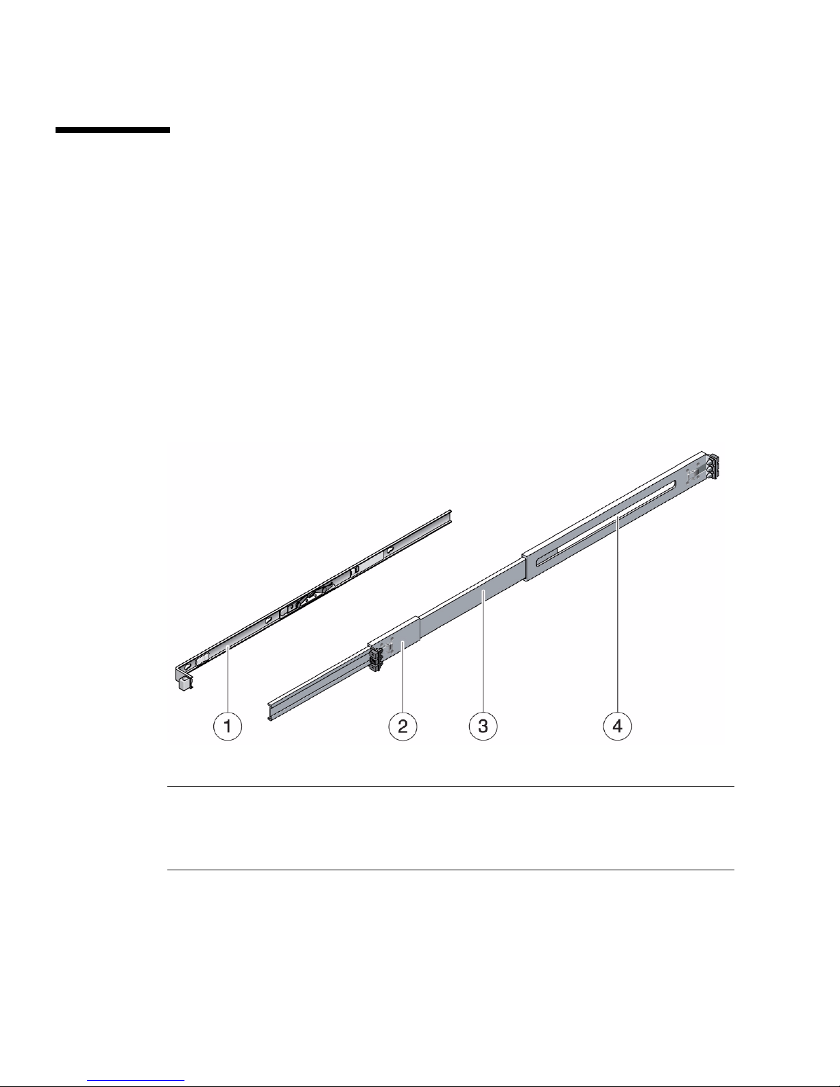
Slide Rail Assemblies
Each slide rail assembly consists of a three-section slide rail and a removable
mounting bracket. The slide rail attaches to the rack posts. The mounting bracket
attaches to the server chassis.
FIGURE: Sections of the Snap-In Slide Rail Assembly
Figure Legend
1 Mounting bracket
2 Front section
3 Middle section
4 Rear section
■ The slide rails adjust to fit rack depths from 24 in. (61 cm) to 36.5 in. (93 cm). The
middle and rear sections of the slide rails have holes for mounting the rail to the
rack posts.
22 SPARC T4-1 Server Installation Guide • August 2013

■ The front section extends out of the middle section, which allows the server to be
positioned far enough out of the rack for many service operations to be
performed.
■ The removable mounting bracket slides 14.5 in. (37 cm) out of the slide rail, then
locks in place. If you unlock the mounting bracket at this point, it slides an
additional 14.5 in. (37 cm) before separating from the slide rail.
There are six locks in a slide rail assembly. Four are on the mounting bracket. Two
locks are on the slide rail.
Installing the Server 23

FIGURE: Locating the Locks on the Slide Rail Assembly
Related Information
■ “Rack Compatibility” on page 19
■ “Install the Slide Rail Assemblies” on page 25
24 SPARC T4-1 Server Installation Guide • August 2013

▼ Install the Slide Rail Assemblies
1. Pull both mounting brackets completely out of their respective slide rails.
a. Simultaneously press and hold the upper and lower lock buttons of the slide
rail lock.
FIGURE: Unlocking the Express Rail Slide Rail Assembly
b. Pull the mounting bracket out until it stops.
c. Slide the mounting bracket release button to the left, then slide the mounting
bracket completely out of the slide rail.
Installing the Server 25

FIGURE: Express Rail Mounting Bracket Release Button
2. Attach a mounting bracket to the right side of the server chassis.
a. Position the mounting bracket against the chassis. Ensure that the slide rail
lock is at the front and the keyed openings on the mounting bracket are
aligned with the locating pins on the side of the chassis.
26 SPARC T4-1 Server Installation Guide • August 2013

FIGURE: Attaching an Express Rail Mounting Bracket to the Chassis
b. Ensure that the heads of the four locating pins protrude through the keyed
openings in the mounting bracket. Slide the mounting bracket toward the
front of the chassis until the bracket locks into place with an audible click.
c. Verify that all four locating pins are trapped in the keyed openings and that
the third locating pin from the front has engaged the mounting bracket lock.
3. Attach the second mounting bracket to the left side of the server chassis.
4. Orient the slide rails, ensuring that the ball bearing tracks (labeled FRONT) are
forward.
Installing the Server 27

FIGURE: Express Rail Slide Rails Orientation for Installation
5. Extend the slide rails (outer section) to fit the rack and attach the slide rails to
the rack.
You hear an audible click when the rails securely attach to the rack.
28 SPARC T4-1 Server Installation Guide • August 2013

FIGURE: Attaching Express Slide Rails to the Rack
Caution – Deploy the antitilt feature on the rack before continuing the installation.
Related Information
■ “Rack Compatibility” on page 19
■ “Slide Rail Assemblies” on page 22
▼ Install the Server
Caution – The weight of the servers on extended slide rails can be enough to
overturn an equipment rack.
Installing the Server 29

Caution – The server weighs approximately 60 lb (25 kg). Two people are required
to lift and mount the server into a rack enclosure.
1. If the rack is equipped with an antitilt bar, verify that it has been deployed and,
if not, deploy it.
2. Insert the ends of the mounting brackets into the sliding rails.
FIGURE: Mounting the Chassis on the Slide Rails
3. While pressing the two green slide rail release buttons, push the server into the
rack until the slide rail locks on the front of the mounting brackets engage the
slide rail assemblies. You will hear a click at that point.
Caution – Before continuing, verify that the server is securely mounted in the rack,
and that the slide rails are locked to the mounting brackets.
30 SPARC T4-1 Server Installation Guide • August 2013

Related Information
■ “Rack Compatibility” on page 19
■ “Slide Rail Assemblies” on page 22
■ “Install the Slide Rail Assemblies” on page 25
■ “Install the CMA” on page 31
■ “Verify Correct Operation of the Slide Rails and the CMA” on page 36
(Optional) Installing the CMA
■ “Install the CMA” on page 31
■ “Verify Correct Operation of the Slide Rails and the CMA” on page 36
▼ Install the CMA
Caution – Support the CMA during this installation. Do not allow the assembly to
hang by its own weight until it is secured by all three attachment points.
1. Remove the tape from the CMA rail extension (on the left of the CMA) and
remove the CMA rail extension.
2. Attach the CMA rail extension to rear left slide rail.
At the rear of the rack, plug the CMA rail extension into the end of the left sliding
rail assembly. The tab at the front of the rail extension clicks into place.
Installing the Server 31

FIGURE: Inserting the CMA Rail Extension Into the Rear of the Left Slide Rail
The right sides of the two CMA arms have hinged extensions. On the
manufacturer’s instruction sheet, the smaller extension is called the CMA
Connector for Inner Member. This extension attaches to the right mounting
bracket. The larger extension is called the CMA Connector for Outer Member, and
attaches to the right sliding rail.
3. Insert the smaller extension into the clip located at the end of the mounting
bracket.
Slide the smaller extension into the square hole on the middle-in-width of the clip
that is located at the end of the mounting bracket.
32 SPARC T4-1 Server Installation Guide • August 2013

FIGURE: Mounting the Inner CMA Connector
4. Insert the larger extension into the end of the right sliding rail.
Installing the Server 33

FIGURE: Attaching the Outer CMA Connector
5. Insert the hinged plastic connector at the left side of the CMA fully into the
CMA rail extension.
The plastic tab on the CMA rail extension locks the hinged plastic connector in
place.
34 SPARC T4-1 Server Installation Guide • August 2013

FIGURE: Mounting the Left Side of the Slide Rail
Related Information
■ “Rack Compatibility” on page 19
■ “Slide Rail Assemblies” on page 22
■ “Install the Slide Rail Assemblies” on page 25
■ “Install the Server” on page 29
■ “Verify Correct Operation of the Slide Rails and the CMA” on page 36
Installing the Server 35

▼ Verify Correct Operation of the Slide
Rails and the CMA
Perform this procedure both before and after you install the server cables in the
CMA. Performing the procedure before the CMA contains cables helps ensure that it
extends and contracts smoothly before the cables are added.
Note – The CMA includes velcro straps to secure the cables inside the CMA. Do not
install the velcro straps until you have installed the CMA, connected the cables, and
placed the cabling inside the CMA.
Tip – Two people are needed for this procedure, one to move the server in and out
of the rack, and one to observe the cables and CMA.
1. For a free-standing rack, deploy the antitilt bar.
2. Unlock the slide lock buttons at the right and left sides of the chassis.
36 SPARC T4-1 Server Installation Guide • August 2013

FIGURE: Unlocking the Slide Rail Assembly
3. If the server cables have been placed inside the CMA, inspect them for binding
or kinks.
4. Slowly pull the server out of the rack until the slide rails reach their stops.
5. Verify that the CMA extends fully and does not bind in the slide rails.
6. Verify that the server extends fully and locks in the maintenance position.
The server should stop after approximately 15 in. (40 cm) of travel.
7. Pull both slide rail release buttons toward you simultaneously and slide the
server back into the rack.
The server should slide smoothly into the rack without binding.
Installing the Server 37

FIGURE: Rail Mounting Bracket Release Button
8. Verify that the CMA retracted without binding.
9. Adjust the cable straps and CMA as required to secure the cables.
Related Information
■ “Rack Compatibility” on page 19
■ “Slide Rail Assemblies” on page 22
■ “Install the Slide Rail Assemblies” on page 25
■ “Install the Server” on page 29
■ “Install the CMA” on page 31
38 SPARC T4-1 Server Installation Guide • August 2013

Connecting Cables
These topics explain how to connect the data and power cables to the server:
Step Description Links
1. Review the cabling requirements. “Cabling Requirements” on page 39
2. Review I/O port connector details. “Identifying Ports” on page 40
3. Connect the management and data
cables.
4. Secure cables in the CMA. “Secure Cables in the CMA” on page 48
“Connecting Data and Management
Ports” on page 44
Cabling Requirements
Review these cabling notes before attaching cables to the server.
■ Minimum cable connections for the server:
■ At least one server on-board Ethernet network connection (NET port)
■ The SER MGT port
■ The NET MGT port
■ A power cable for each power supply
■ SP management ports: There are two management ports for use with the SP.
■ The SER MGT port uses an RJ-45 cable and is always available. This port is the
default connection to the SP.
■ The NET MGT port is the optional connection to the SP. This port becomes
available after you configure network settings for the SP (through the SER MGT
port).
The NET MGT port uses an RJ-45 cable for a 10/100 BASE-T connection. This
port does not support connections to Gigabit networks.
39

■ Ethernet ports are labeled NET0, NET1, NET2, and NET3. The Ethernet interfaces
operate at 10 Mbps, 100 Mbps, and 1000 Mbps.
TABLE: Ethernet Connection Transfer Rates
Connection Type IEEE Terminology Transfer Rate
Ethernet 10BASE-T 10 Mbit/sec
Fast Ethernet 100BASE-TX 100 Mbits/sec
Gigabit Ethernet 1000BASE-T 1000 Mbit/sec
■ VGA DB-15 video port: Use the video port to attach a color monitor to the server.
■ USB Ports: USB ports support hot-plugging. You can connect and disconnect USB
cables and peripheral devices without affecting system operations.
■ You can only perform USB hot-plug operations while the OS is running. USB
hot-plug operations are not supported when the system ok prompt is displayed
or before the system has completed booting.
■ You can connect up to 126 devices to each of the four USB controllers, for a total
of 504 USB devices per system.
■ Power cables: Do not attach power cables to the power supplies until you have
finished connecting the data cables, and have connected the server to a serial
terminal or a terminal emulator (PC or workstation).
Note – The server goes into Standby mode and the SP initializes as soon as a power
cable connects a power supply to an external power source. System messages might
be lost after 60 seconds if a terminal or terminal emulator is not connected to the SER
MGT port before power is applied.
Related Information
■ “Connecting Cables” on page 39
■ “Identifying Ports” on page 40
Identifying Ports
These topics provide reference information about the front and rear panel ports and
pin assignments.
■ “USB Ports” on page 41
40 SPARC T4-1 Server Installation Guide • August 2013

■ “SER MGT Port” on page 41
■ “NET MGT Port” on page 42
■ “Gigabit Ethernet Ports” on page 43
■ “Video Port” on page 43
USB Ports
Two USB ports can be accessed on the server’s front panel and two on the rear panel.
Each Each USB port supplies 5V output at 500 mA.
FIGURE: USB Connector
Figure Legend
1 +5V supply 3 Data +
2 Data - 4 Ground
Related Information
■ “Front Panel Components” on page 3
■ “Rear Panel Components” on page 6
SER MGT Port
The SER MGT RJ-45 port, located on the rear panel, provides the default connection
to the system console.
Connecting Cables 41

FIGURE: SER MGT Port
Figure Legend
1 Clear to Send 5 Ground
2 Data Carrier Detect 6 Receive Data
3 Transmit Data 7 Data Terminal Ready
4 Ground 8 Ready to Send
Related Information
■ “Front Panel Components” on page 3
■ “Rear Panel Components” on page 6
■ “Connect the SER MGT Port Cable” on page 44
■ “Connect a Terminal or Emulator to the SER MGT Port” on page 52
NET MGT Port
The NET MGT RJ-45 port, located on the rear panel, provides an optional Ethernet
connection to the service processor.
FIGURE: NET MGT Port
Figure Legend
1 Transmit Data + 5 No Connect
2 Transmit Data – 6 Receive Data –
3 Receive Data + 7 No Connect
4 No Connect 8 No Connect
42 SPARC T4-1 Server Installation Guide • August 2013

Related Information
■ “Front Panel Components” on page 3
■ “Rear Panel Components” on page 6
■ “Connect the NET MGT Port Cable” on page 45
■ “Assign a Static IP Address to the SP” on page 55
Gigabit Ethernet Ports
Four RJ-45 Gigabit-Ethernet connectors (NET0, NET1, NET2, NET3) are located on
the rear panel. The Ethernet interfaces operate at 10 Mbit/sec, 100 Mbit/sec, and
1000 Mbit/sec.
FIGURE: Gigabit Ethernet Port
Figure Legend
1 Transmit/Receive Data 0 + 5 Transmit/Receive Data 2 –
2 Transmit/Receive Data 0 – 6 Transmit/Receive Data 1 –
3 Transmit/Receive Data 1 + 7 Transmit/Receive Data 3 +
4 Transmit/Receive Data 2 + 8 Transmit/Receive Data 3 –
Related Information
■ “Front Panel Components” on page 3
■ “Rear Panel Components” on page 6
■ “Connect the NET MGT Port Cable” on page 45
Video Port
The server has one 15-pin VGA video port located on the server ’s rear panel.
Maximum supported resolution is 1024 x 768.
Connecting Cables 43

FIGURE: Video Connector
Figure Legend
1 Red Video 9 +5V
2 Green Video 10 Sync Ground
3 Blue Video 11 Monitor ID - Bit 0 (Ground)
4 Monitor ID - Bit 2 (Ground) 12 VGA 12C Serial Data
5 Ground 13 Horizontal Sync
6 Red Ground 14 Vertical Sync
7 Green Ground 15 VGA 12C Serial Clock
8 Blue Ground
Related Information
■ “Rear Panel Components” on page 6
Connecting Data and Management Ports
■ “Connect the SER MGT Port Cable” on page 44
■ “Connect the NET MGT Port Cable” on page 45
■ “Connect the Ethernet Network Cables” on page 46
■ “Connect Other Data Cables” on page 47
▼ Connect the SER MGT Port Cable
The SER MGT port is the farthest left RJ-45 port on the rear panel.
● Connect a Category 5 cable from the SER MGT port to the terminal device.
44 SPARC T4-1 Server Installation Guide • August 2013

FIGURE: SER MGT port – Rear Panel
This port is needed to set up the NET MGT port.
When connecting a DB-9 cable, use an RJ-45 to DB-9 adapter to perform the
crossovers given for each connector.
Note – Use the SER MGT port only for server management. This port is the default
connection between the SP and a terminal or a computer.
Caution – Do not attach a modem to this port.
Related Information
■ “Connect the NET MGT Port Cable” on page 45
■ “Connecting Cables” on page 39
▼ Connect the NET MGT Port Cable
The NET MGT port is located just to the right of the SER MGT port on the rear panel.
● Connect a Category 5 cable from the NET MGT port to your network switch or
hub.
Connecting Cables 45

FIGURE: NET MGT port – Rear Panel
Note – This port is not operational until you configure the network settings (through
the SER MGT port).
Note – The NET MGT port is configured by default to retrieve network settings with
Dynamic Host Configuration Protocol (DHCP) and allow connections using SSH.
You might need to modify these settings for your network. Instructions are given in
“Powering On the Server for the First Time” on page 51.
Related Information
■ “Connect the SER MGT Port Cable” on page 44
■ “Connecting Cables” on page 39
▼ Connect the Ethernet Network Cables
The server has four RJ-45 Gigabit Ethernet network connectors. They are marked
NET0, NET1, NET2, and NET3.
1. Connect a Category 5 cable from your network switch or hub to Ethernet Port 0
(NET0) on the rear of the chassis.
NET0 is the farthest left port in the 4-port network cluster.
46 SPARC T4-1 Server Installation Guide • August 2013

FIGURE: Ethernet Network Ports – Rear Panel
2. Connect Category 5 cables from your network switch or hub to the remaining
Ethernet ports (NET1, NET2, NET3), as needed.
Related Information
■ “Connecting Cables” on page 39
▼ Connect Other Data Cables
● If your server configuration includes PCIe expansion modules, connect the
appropriate I/O cables to their connectors.
Connecting Cables 47

FIGURE: PCIe and PCIe/XAUI Slot Configuration
Figure Legend
1 PCIe slot 0 or XAUI slot 0 4 PCIe slot 3 or XAUI slot 1
2 PCIe slot 1 5 PCIe slot 4
3 PCIe slot 2 6 PCIe slot 5
Related Information
■ “Connecting Cables” on page 39
▼ Secure Cables in the CMA
1. Once the server cables are connected and placed inside the CMA, open the
velcro cable straps and wrap the straps around the CMA securing the cables
inside the CMA.
48 SPARC T4-1 Server Installation Guide • August 2013

FIGURE: Securing the Server Cables With the CMA and Velcro Straps
2. Verify the operation of the slide rails and CMA, and cable service loops.
Repeat the steps described in the procedure: “Verify Correct Operation of the Slide
Rails and the CMA” on page 36.
Related Information
■ “Install the CMA” on page 31
■ “Verify Correct Operation of the Slide Rails and the CMA” on page 36
Connecting Cables 49

50 SPARC T4-1 Server Installation Guide • August 2013

Powering On the Server for the First
Time
These topics provide instructions for booting Oracle’s SPARC T4-1 server for the first
time and for enabling the NET MGT port. It consists of the following topics:
Step Description Links
1. Review the behavior of Oracle ILOM console output
when the system is powered on the first time.
2. Connect the server to a terminal display. “Connect a Terminal or Emulator to the SER MGT
3. Power on the server. “Power On the Server for the First Time” on page 53
4. Check that the server is operational. “Verify Functionality” on page 55
5. (Optional) Assign a static IP address to the SP. “Assigning a Static IP Address to the SP” on
6. Review the Oracle Solaris OS configuration
parameter descriptions.
“Oracle ILOM System Console” on page 51
Port” on page 52
page 55
“Oracle Solaris OS Configuration Parameters” on
page 57
Oracle ILOM System Console
When you power on the system, the boot process begins under the control of the
Oracle ILOM system console. The system console displays status and error messages
generated by firmware-based tests that are run during system startup.
Note – To see these status and error messages, connect a terminal or terminal
emulator to the SER MGT port before power is applied to the server.
51

After the system console finishes its low-level system diagnostics, the SP initializes
and runs a suite of higher level diagnostics. When you access the SP using a device
connected to the SER MGT port, you see the output of the Oracle ILOM diagnostics.
By default, the SP configures the NET MGT port automatically, retrieving network
configuration settings using the Dynamic Host Configuration Protocol (DHCP) and
allowing connections using SSH.
For a more detailed discussion on configuring the system console and connecting
terminals, refer to the system administration documentation for your server.
Related Information
■ “Connect a Terminal or Emulator to the SER MGT Port” on page 52
■ “Power On the Server for the First Time” on page 53
▼ Connect a Terminal or Emulator to the
SER MGT Port
A null modem configuration is needed for DTE to DTE communications. You can use
the supplied RJ-45 crossover adapter with a standard RJ-45 cable to achieve the null
modem configuration.
1. Connect a terminal or a terminal emulator (PC or workstation) to the SER MGT
port.
2. Configure the terminal or terminal emulator with these settings:
■ 9600 baud
■ 8 bits
■ No parity
■ 1 Stop bit
■ No handshake
3. (Optional) Connect an Ethernet cable between the server’s NET MGT port and
the network to which future connections to the SP and host will be made.
Related Information
■ “Oracle ILOM System Console” on page 51
■ “Power On the Server for the First Time” on page 53
52 SPARC T4-1 Server Installation Guide • August 2013

▼ Power On the Server for the First Time
1. Confirm that you have completed all of the preparations for installation.
See the instructions in “Confirming Server and Site Specifications” on page 1.
2. Confirm that you have completed the installation of the server in its rack.
See the instructions in “Installing the Server” on page 19.
3. (Recommended) Connect an Ethernet cable between one of the server’s NET
ports and the network to which the server will communicate.
Note – After the initial configuration of the system, communication with the SP and
host is usually performed through an Ethernet interface.
4. Plug the power cords into the power supplies and into separate power sources.
To provide redundancy, plug both power supplies into separate power sources.
The system can operate with only one power connection, but there is no
redundancy in this case.
The SP runs on the 3.3V standby voltage. As soon as AC power is connected to the
server, the SP powers on, runs diagnostics, and initializes the Oracle ILOM
firmware.
After a few minutes, the SP login prompt appears on the terminal device. The host
is not initialized or powered on yet.
5. At the terminal device, log in to the SP as root with a password of changeme.
hostname login: root
Password: changeme
. . .
->
6. Change the root password.
...
Warning: password is set to factory default.
-> set /SP/users/root password
Enter new password: ********
Enter new password again: ********
->
Powering On the Server for the First Time 53

7. Power on the server and redirect the host output to display on the serial
terminal device:
-> start /SYS
Are you sure you want to start /SYS (y/n)? y
-> start /HOST/console
Are you sure you want to start /HOST/CONSOLE (y/n)? y
Serial console started. To stop, type #.
. . .
After you start the HOST console, the server initialization takes approximately 20
minutes to complete.
8. Configure the OS by entering parameter values as prompted by a series of
onscreen instructions.
Tip – If you are not sure how to respond to a particular value, you can accept the
default and make changes at another time when the OS is running.
Note – You will be prompted to confirm the configuration multiple times. You will
be able to change parameter values if desired at each of these confirmation points.
9. (Optional) Deploy the server for its intended use.
Once the server has been configured and you have changed the default password,
the server is ready for normal use.
Related Information
■ “Connect a Terminal or Emulator to the SER MGT Port” on page 52
■ “Connecting Cables” on page 39
■ “Assign a Static IP Address to the SP” on page 55
54 SPARC T4-1 Server Installation Guide • August 2013
▼ Verify Functionality
● After powering on the system for the first time, use the Sun Validation Test
Suite (Sun VTS) software to verify the functionality and performance of the
system, including network connections.
Refer to the Sun VTS documentation for instructions on running these test
utilities, available at:
http://www.oracle.com/pls/topic/lookup?ctx=OracleVTS7.0
Assigning a Static IP Address to the SP
■ “Assign a Static IP Address to the SP” on page 55
■ “Oracle Solaris OS Configuration Parameters” on page 57
▼ Assign a Static IP Address to the SP
If the network your server is connected to does not support DHCP for IP addressing,
perform the following procedure to update the OS configuration to static IP
addressing and to assign a static IP address to the SP.
1. Set the SP to accept a Static IP Address.
-> set /SP/network pendingipdiscovery=static
Set 'pendingipdiscovery' to 'static'
2. Set the IP address for the SP.
-> set /SP/network pendingipaddress=service-processor-IPaddr
Set 'pendingipaddress' to 'service-processor-IPaddr'
3. Set the IP address for the SP gateway.
-> set /SP/network pendingipgateway=gateway-IPaddr
Set 'pendingipgateway' to 'gateway-IPaddr'
Powering On the Server for the First Time 55

4. Set the netmask for the SP.
-> set /SP/network pendingipnetmask=255.255.255.0
Set 'pendingipnetmask' to '255.255.255.0'
This example uses 255.255.255.0 to set the netmask. Your network
environment subnet might require a different netmask. Use a netmask number
most appropriate to your environment.
5. Use the show /SP/network command to verify that the parameters were set
correctly.
-> show /SP/network
/SP/network
Targets:
interconnect
ipv6
test
Properties:
commitpending = (Cannot show property)
dhcp_server_ip = none
ipaddress = xxx.xxx.xxx.xxx
ipdiscovery = static
ipgateway = xxx.xxx.xxx.xxx
ipnetmask = 255.255.252.0
macaddress = xx:xx:xx:xx:xx:xx
pendingipaddress = xxx.xxx.xxx.xxx
pendingipdiscovery = static
pendingipgateway = xxx.xxx.xxx.xxx
pendingipnetmask = 255.255.255.0
sidebandmacaddress = xx:xx:xx:xx:xx:xx
state = enabled
Commands:
cd
set
show
->
6. Commit the changes to the SP network parameters.
-> set /SP/network commitpending=true
Set 'commitpending' to 'true'
56 SPARC T4-1 Server Installation Guide • August 2013

Note – You can run the show /SP/network command again (after performing the
set /SP/network commitpending=true command) to verify that the
parameters have been updated.
Related Information
■ “Power On the Server for the First Time” on page 53
Oracle Solaris OS Configuration Parameters
When configuring the Oracle Solaris OS, you will be prompted for the following
configuration parameters. For more information about these settings, refer to the
Oracle Solaris documentation.
Parameter Description
Language Select a number from the displayed languages list.
Locale Select a number from the displayed locale list.
Terminal Type Select a terminal type that corresponds with your terminal device.
Network? Select Yes.
Multiple Network Interfaces Select the network interfaces that you plan to configure. If you are not sure,
select the first one in the list.
DHCP? Select Yes or No according to your network environment.
Host Name Type the host name for the server.
IP Address Type the IP address for this Ethernet interface.
Subnet? Select Yes or No according to your network environment.
Subnet Netmask If your answer to Subnet? was Yes, type the netmask for the subnet for your
network environment.
IPv6? Specify whether or not to use IPv6. If you are not sure, select No to
configure the Ethernet interface for IPv4.
Security Policy Select either standard UNIX security (no) or Kerberos Security (Yes). If you
are not sure, select No.
Confirm When prompted with this, review the onscreen information and change it if
needed. Otherwise, continue.
Name Service Select the name service according to your network environment.
Note – If you select a name service other than None, you will be prompted
for additional name service configuration information.
Powering On the Server for the First Time 57

Parameter Description
NFSv4 Domain Name Select the type of domain name configuration according to your
environment. If you are not sure, select Use the NFSv4 domain
derived by the system.
Time Zone (Continent) Select your continent.
Time Zone (Country or Region) Select your country or region.
Time Zone Select the time zone.
Date and Time Accept the default date and time, or change the values.
root Password Type the root password twice. This password is for the superuser account
for the Oracle Solaris OS on this server. This password is not the SP
password.
Related Information
■ “Oracle ILOM System Console” on page 51
■ “Connect a Terminal or Emulator to the SER MGT Port” on page 52
■ “Power On the Server for the First Time” on page 53
58 SPARC T4-1 Server Installation Guide • August 2013

Glossary
A
ANSI SIS American National Standards Institute Status Indicator Standard.
ASF Alert standard format (Netra products only).
ASR Automatic system recovery.
AWG American wire gauge.
B
blade Generic term for server modules and storage modules. See server module and
storage module.
blade server Server module. See server module.
BMC Baseboard management controller.
BOB Memory buffer on board.
C
chassis For servers, refers to the server enclosure. For server modules, refers to the
modular system enclosure.
CMA Cable management arm.
59

CMM Chassis monitoring module. The CMM is the service processor in the
modular system. Oracle ILOM runs on the CMM, providing lights out
management of the components in the modular system chassis. See Modular
system and Oracle ILOM.
CMM Oracle ILOM Oracle ILOM that runs on the CMM. See Oracle ILOM.
D
DHCP Dynamic Host Configuration Protocol.
disk module or
disk blade
DTE Data terminal equipment.
E
EIA Electronics Industries Alliance.
ESD Electrostatic discharge.
F
FEM Fabric expansion module. FEMs enable server modules to use the 10GbE
FRU Field-replaceable unit.
Interchangeable terms for storage module. See storage module.
connections provided by certain NEMs. See NEM.
H
HBA Host bus adapter.
host The part of the server or server module with the CPU and other hardware
that runs the Oracle Solaris OS and other applications. The term host is used
to distinguish the primary computer from the SP. See SP.
60 SPARC T4-1 Server Installation Guide • August 2013

I
ID PROM Chip that contains system information for the server or server module.
IP Internet Protocol.
K
KVM Keyboard, video, mouse. Refers to using a switch to enable sharing of one
keyboard, one display, and one mouse with more than one computer.
L
LwA Sound power level.
M
MAC Machine access code.
MAC address Media access controller address.
Modular system The rackmountable chassis that holds server modules, storage modules,
NEMs, and PCI EMs. The modular system provides Oracle ILOM through its
CMM.
MSGID Message identifier.
N
name space Top-level Oracle ILOM CMM target.
NEBS Network Equipment-Building System (Netra products only).
Glossary 61

NEM Network express module. NEMs provide 10/100/1000 Mbps Ethernet,
10GbE Ethernet ports, and SAS connectivity to storage modules.
NET MGT Network management port. An Ethernet port on the server SP, the server
module SP, and the CMM.
NIC Network interface card or controller.
NMI Nonmaskable interrupt.
O
OBP OpenBoot PROM.
Oracle ILOM Oracle Integrated Lights Out Manager. Oracle ILOM firmware is preinstalled
on a variety of Oracle systems. Oracle ILOM enables you to remotely
manage your Oracle servers regardless of the state of the host system.
Oracle Solaris OS Oracle Solaris operating system.
P
PCI Peripheral component interconnect.
PCI EM PCIe ExpressModule. Modular components that are based on the PCI
Express industry-standard form factor and offer I/O features such as Gigabit
Ethernet and Fibre Channel.
POST Power-on self-test.
PROM Programmable read-only memory.
PSH Predictive self healing.
Q
QSFP Quad small form-factor pluggable.
62 SPARC T4-1 Server Installation Guide • August 2013

R
REM RAID expansion module. Sometimes referred to as an HBA See HBA.
Supports the creation of RAID volumes on drives.
S
SAS Serial attached SCSI.
SCC System configuration chip.
SER MGT Serial management port. A serial port on the server SP, the server module SP,
and the CMM.
server module Modular component that provides the main compute resources (CPU and
memory) in a modular system. Server modules might also have onboard
storage and connectors that hold REMs and FEMs.
SP Service processor. In the server or server module, the SP is a card with its
own OS. The SP processes Oracle ILOM commands providing lights out
management control of the host. See host.
SSD Solid-state drive.
SSH Secure shell.
storage module Modular component that provides computing storage to the server modules.
T
TIA Telecommunications Industry Association (Netra products only).
Tma Maximum ambient temperature.
U
UCP Universal connector port.
Glossary 63

UI User interface.
UL Underwriters Laboratory Inc.
US. NEC United States National Electrical Code.
UTC Coordinated Universal Time.
UUID Universal unique identifier.
W
WWN World wide name. A unique number that identifies a SAS target.
64 SPARC T4-1 Server Installation Guide • August 2013

Index
A
acoustic noise emissions, 12
adapters for serial cables, 45
airflow requirements, 12
ambient temperature range, 11
anti-tilt legs or bar, 21
B
baud rate for serial terminal, 52
bits setting for serial terminal, 52
booting the system, 51
buttons, See "slide rail assembly locks"
C
cable management assembly, 38
cables
adapters for serial data cables, 45
clearance, 9
configuring
Oracle Solaris OS, 57
CPU description, 2
D
diagnostics, when run, 53
drives, 2
E
environmental requirements, 11
Ethernet ports
described, 2
pinouts, 43
H
handshaking for serial terminal, no, 52
hot-plugging USB ports, 40
humidity, ambient relative, 11
I
installing
mounting brackets, 25
server into rack, 19
L
levers, locking, See "slide rail assembly locks"
locating pins for mounting brackets, 25
locks, See "slide rail assembly locks"
M
memory description, 2
minimum cable connections, 39
modem not to be used with the SER MGT port, 45
mounting bracket
locating pins on chassis, 25
preparation for installation, 25
removing from slide rail, 25
unlocking, 25
N
network management (NET MGT) port
pinouts, 42
O
Oracle Solaris OS
configuration parameters, 57
P
parity for serial terminal, no, 52
PCIe cards
slots, 2
pinouts
Ethernet ports, 43
65

NET MGT port, 42
SER MGT port, 41
USB ports, 41
video port, 43, 44
pins, mounting bracket locating, 25
power supplies, 2
R
rack
compatibility, 19
mounting holes, supported, 20
specifications, 19
stabilizing, 21
rackmount
anti-tilt legs or bar, extending, 21
kit, 19
racks, supported, 19
safety warnings, 20
stabilizing the rack, 21
RJ-45 cable, 39
S
SER MGT port, 41
server overview, 1
service processor
powering on for the first time, 53
shipping kit contents, 15
SP (service processor), 2
specifications
acoustic, 12
environmental requirements, 11
physical, 9
server, 8
standby voltage, 3.3v, 53
stop bit, 52
V
video port
described, 2
pinouts, 43
resolution, 43
use of, 40
T
temperature requirements, 11
U
unlocking mounting bracket, 25
USB ports
described, 2
function, 40
output power, 41
pinouts, 41
66 SPARC T4-1 Server Installation Guide • August 2013
 Loading...