


Sun Netra T5220 Server
Installation Guide
Part No. E21356-01
November 2011, Revision A

Copyright ©2008, 2011, Oracleand/or itsaffiliates. Allrights reserved.
This softwareand related documentation are providedunder alicense agreement containing restrictions onuse anddisclosure andare protected by
intellectual propertylaws. Exceptas expressly permitted in your license agreementor allowedby law, you may not use, copy, reproduce,translate,
broadcast, modify,license, transmit,distribute, exhibit,perform, publish,or displayany part,in anyform, orby anymeans. Reverseengineering,
disassembly, or decompilation of this software,unless required by law for interoperability, isprohibited.
The informationcontained hereinis subjectto changewithout noticeand isnot warrantedto beerror-free.If youfind anyerrors, please report them to us
in writing.
If thisis softwareor related softwaredocumentation thatis deliveredto theU.S. Governmentor anyonelicensing iton behalfof theU.S. Government,the
following noticeis applicable:
U.S. GOVERNMENTRIGHTS. Programs,software, databases, and related documentation and technical data deliveredto U.S.Government customers
are "commercial computer software" or"commercial technicaldata" pursuantto theapplicable FederalAcquisition Regulationand agency-specific
supplemental regulations.As such,the use,duplication, disclosure, modification, and adaptation shall be subject to the restrictionsand licenseterms set
forth inthe applicableGovernment contract,and, tothe extentapplicable bythe termsof theGovernment contract,the additionalrights setforth inFAR
52.227-19, CommercialComputer Software License (December 2007). Oracle America, Inc., 500 Oracle Parkway, Redwood City, CA 94065.
This software or hardware isdeveloped for general use in a variety of informationmanagement applications.It is not developed or intended for use inany
inherently dangerous applications, including applications which may create arisk ofpersonal injury. If you use this software orhardware in dangerous
applications, thenyou shallbe responsibleto takeall appropriate fail-safe, backup, redundancy, and other measures toensure its safe use. Oracle
Corporation andits affiliatesdisclaim anyliability forany damagescaused byuse ofthis software or hardware indangerous applications.
Oracle andJava areregistered trademarks of Oracle and/or its affiliates.Other namesmay betrademarks oftheir respective owners.
Intel andIntel Xeonare trademarksor registered trademarksof IntelCorporation. AllSPARC trademarks are used under license and aretrademarks or
registered trademarks of SPARCInternational, Inc. AMD, Opteron, theAMD logo,and theAMD Opteron logo are trademarksor registered trademarksof
Advanced MicroDevices. UNIXis aregistered trademark of The Open Group.
This software or hardware and documentation may provide access to or information on content, products, and services from third parties. Oracle
Corporation and its affiliates are not responsible for and expressly disclaim all warranties of any kind with respect to third-party content, products, and
services. Oracle Corporation and its affiliates will not be responsible for any loss, costs, or damages incurred due to your access to or use of third-party
content, products, or services.
Copyright ©2008, 2011, Oracleet/ou sesaffiliés. Tous droits réservés.
Ce logicielet ladocumentation quil’accompagne sontprotégés parles loissur lapropriété intellectuelle. Ils sont concédés sous licence et soumis à des
restrictions d’utilisationet dedivulgation. Saufdisposition devotre contrat de licence ou de la loi, vous ne pouvez pas copier, reproduire, traduire,
diffuser, modifier, breveter, transmettre, distribuer, exposer, exécuter, publier ou afficher le logiciel, même partiellement, sous quelque forme et par
quelque procédéque cesoit. Parailleurs, ilest interdit de procéder àtoute ingénierieinverse dulogiciel, dele désassemblerou dele décompiler, exceptéà
des finsd’interopérabilité avecdes logicielstiers outel queprescrit par la loi.
Les informationsfournies dansce documentsont susceptiblesde modificationsans préavis.Par ailleurs,Oracle Corporationne garantitpas qu’elles
soient exemptesd’erreurs etvous invite,le caséchéant, àlui enfaire part par écrit.
Si celogiciel, oula documentationqui l’accompagne,est concédésous licenceau Gouvernementdes Etats-Unis,ou àtoute entitéqui délivrela licencede
ce logicielou l’utilisepour lecompte duGouvernement desEtats-Unis, lanotice suivantes’applique :
U.S. GOVERNMENTRIGHTS. Programs,software, databases, and related documentation and technical data deliveredto U.S.Government customers
are "commercial computer software" or"commercial technicaldata" pursuantto theapplicable FederalAcquisition Regulationand agency-specific
supplemental regulations. As such, theuse, duplication,disclosure, modification, and adaptation shall be subject to the restrictions and license terms set
forth inthe applicableGovernment contract,and, tothe extentapplicable bythe termsof theGovernment contract,the additionalrights setforth inFAR
52.227-19, CommercialComputer Software License (December 2007). Oracle America, Inc., 500 Oracle Parkway, Redwood City, CA 94065.
Ce logicielou matériela étédéveloppé pourun usagegénéral dansle cadred’applications degestion desinformations. Celogiciel oumatériel n’estpas
conçu nin’est destinéà êtreutilisé dansdes applicationsà risque,notamment dansdes applicationspouvant causerdes dommagescorporels. Si vous
utilisez celogiciel oumatériel dansle cadred’applications dangereuses, il est de votre responsabilitéde prendre toutesles mesuresde secours,de
sauvegarde, deredondance et autres mesures nécessaires à son utilisation dans des conditions optimales de sécurité. Oracle Corporation et ses affiliés
déclinent touteresponsabilité quantaux dommagescausés parl’utilisation dece logicielou matérielpour cetype d’applications.
Oracle etJava sontdes marquesdéposées d’OracleCorporation et/oude sesaffiliés.Tout autre nom mentionné peut correspondre àdes marques
appartenant àd’autres propriétaires qu’Oracle.
Intel etIntel Xeonsont desmarques oudes marques déposées d’Intel Corporation. Toutesles marques SPARC sontutilisées souslicence etsont des
marques oudes marques déposées de SPARC International,Inc. AMD,Opteron, le logo AMD et le logo AMD Opteron sont des marques oudes marques
déposées d’AdvancedMicro Devices.UNIX estune marque déposée d’The Open Group.
Ce logicielou matérielet ladocumentation quil’accompagne peuventfournir desinformations oudes liensdonnant accèsà descontenus, desproduits et
des servicesémanant detiers. OracleCorporation etses affiliésdéclinent touteresponsabilité ou garantie expresse quant aux contenus, produits ou
services émanantde tiers.En aucuncas, OracleCorporation etses affiliésne sauraientêtre tenus pour responsables des pertes subies, des coûts
occasionnés oudes dommagescausés parl’accès àdes contenus,produits ouservices tiers,ou àleur utilisation.
Please
Recycle

Contents
Preface vii
1. Sun Netra T5220 Features Overview 1
Sun Netra T5220 Server 2
Chassis Identification 3
Features at a Glance 5
Chip-Multitheaded Processor and Memory Technology 7
Performance Enhancements 8
Preinstalled Solaris Operating System 8
Hardware-Assisted Cryptography 9
Support for Virtualization Through
Logical Domains (LDoms) 9
Remote Manageability With ILOM 10
High Levels of System Reliability, Availability, and Serviceability 11
Hot-Pluggable and Hot-Swappable Components 11
Power Supply Redundancy 11
Environmental Monitoring 12
Support for RAID Storage Configurations 12
Error Correction and Parity Checking 12
Fault Management and Predictive Self Healing 13
iii

Rackmountable Enclosure 13
2. Preparing for Installation 15
Server and Rack Installation Measurements 15
Tools and Equipment Needed 16
Shipping Kit Inventory List 16
Optional Component Installation 17
ESD Precautions 17
Installation Overview 17
Safety Precautions 19
3. Mounting the Server Into a 4-Post Rack 21
4-Post Rackmounting Options 22
Hardmounting the Server in a 19-Inch 4-Post Rack 22
▼ To Install a Server With a Hardmount 19-Inch 4-Post Rack 22
Mounting the Server in a Sliding Rail Mount 19-Inch 4-Post Rack 26
▼ To Install a Server With a Sliding Rail Mount in a 19-Inch 4-Post Rack 26
Hardmounting the Server in a 600-mm 4-Post Rack 33
▼ To Install a Server With a Hardmount in a 600-mm 4-Post Rack 33
4. Mounting the Server Into a 2-Post Rack 41
2-Post Rackmounting Options 42
Hardmounting the Server in a 23-Inch 2-Post Rack 43
▼ To Install a Server With a Hardmount in a 23-Inch 2-Post Rack 43
Hardmounting the Server in a 19-Inch 2-Post Rack 48
▼ To Install a Server With a Hardmount in a 19-Inch 2-Post Rack 48
Mounting the Server With a Sliding Rail Mount in a 19-Inch 2-Post Rack 54
▼ To Install a Server With a Sliding Rail Mount in a 19-Inch 2-Post Rack 54
5. Cabling the Server 65
iv Sun Netra T5220 Server Installation Guide • November 2011

Cable Connections and Ports 65
Connector Locations 67
Status Indicator Locations 68
Connecting the Server Cables 69
▼ To Connect the Service Processor Serial Management Port 70
▼ To Connect the Service Processor Network Management Port 71
▼ To Connect the Ethernet Network Cables 71
▼ To Connect AC Power Cables to the Server 72
DC Operation Conditions and Procedures 73
DC Power Source Requirements 73
DC Supply and Ground Conductor Requirements 74
Overcurrent Protection Requirements 75
▼ To Assemble the DC Input Power Cable 75
6. Powering On the System 79
Powering On the System for the First Time 79
ILOM System Console 79
ILOM Service Processor 80
CLIs, User Accounts, and Passwords for Connecting to the ILOM Service
Processor 80
▼ To Power On the System for the First Time 81
▼ To Avoid Booting the Solaris Operating System at Start Up 83
Enabling the Service Processor Network Management Port 83
Logging In To the Service Processor 84
▼ To Log In To the Service Processor Using the Serial Management Port 84
Configuring the Service Processor Network Management Port 86
▼ To Configure the Service Processor Network Management Port 87
▼ To Reset the Service Processor 89
▼ To Log In To the Service Processor Using the Network Management Port
90
Contents v

Using the Service Processor for Common Operations 90
▼ To Power On the System 91
▼ To Connect to the System Console 92
▼ To Perform a Normal System Initialization 92
Booting the Solaris Operating System 94
▼ To Boot the Solaris Operating System 94
▼ To Reset the System 96
▼ To Power Cycle the System 96
Verifying System Functionality 97
A. Updating the Firmware 99
Updating the Firmware 99
▼ To Update the Firmware 99
B. Selecting a Boot Device 103
Selecting a Boot Device 103
▼ To Select a Boot Device 103
Index 105
vi Sun Netra T5220 Server Installation Guide • November 2011

Preface
This installation guide explains how to install, cable and power on the Sun Netra
T5220 server from Oracle. This document is written for technicians, system
administrators, authorized service providers, and users who have advanced
experience troubleshooting and replacing hardware.
Note – All internal components except hard drives must be installed by qualified
service technicians only.
■ Product Notes
■ Related Documentation
■ Feedback
■ Support and Accessibility
Product Notes
For late-breaking information and known issues about this product, refer to the
products notes at:
http://download.oracle.com/docs/cd/E19350-01/index.html
vii

Related Documentation
Documentation Link
All Oracle products http://www.oracle.com/documentation
your-product-name http://download.oracle.com/docs/cd/E19350-01/index.html
other-product-name http://download.oracle.com/docs/cd/E19874-01/index.html
Oracle Solaris OS and systems
software library
Feedback
Provide feedback about this documentation at:
http://www.oracle.com/goto/docfeedback
Support and Accessibility
http://www.oracle.com/technetwork/indexes/documentation/
index.html#sys_sw
Description Links
Access electronic support through
My Oracle Support
Learn about Oracle’s commitment to
accessibility
viii Sun Netra T5220 Server Installation Guide • November 2011
http://support.oracle.com
For hearing impaired:
http://www.oracle.com/accessibility/support.html
http://www.oracle.com/us/corporate/accessibility/
index.html

Preface ix

x Sun Netra T5220 Server Installation Guide • November 2011

CHAPTER
1
Sun Netra T5220 Features Overview
This chapter describes the features of the Sun Netra T5220 server. Topics include:
■ “Sun Netra T5220 Server” on page 2
■ “Features at a Glance” on page 5
■ “Performance Enhancements” on page 8
■ “High Levels of System Reliability, Availability, and Serviceability” on page 11
■ “Fault Management and Predictive Self Healing” on page 13
Note – Review the Sun Netra T5220 Server Product Notes (820-3014) for the most
recent system firmware release. The system firmware postings contain a README
file detailing the fixes and new features.
1

Sun Netra T5220 Server
The Sun Netra T5220 server is a 2-rack unit (2U) server.
The Sun Netra T5220 server is a scalable, reliable, high-performance, entry-level
server, optimized for enterprise data centers. The server offers the following key
features:
■ The UltraSPARC T2 multicore processor with CoolThreads technology for high-
throughput and energy savings.
■ High levels of system uptime through the processor and memory reliability-
availability-serviceability (RAS) features, coupled with redundancy of some
system components, support for hardware RAID (0+1), and the predictive selfhealing features of the Solaris™ 10 Operating System (Solaris OS).
■ A space efficient, rack-optimized form factor 2U chassis.
■ Investment protection with SPARC V9 binary application compatibility and the
Solaris 10 OS. The Solaris 10 OS also provides features such as Solaris Predictive
Self-Healing, Solaris Dynamic Tracing, and support across UltraSPARC platforms.
■ Unified server management though the use of the Integrated Lights Out Manager
(ILOM) system controller interface. ILOM integrates and manages CoolThreads
and x64 platforms with the same tool set, and in heterogeneous environments,
using industry standard element management tools and enterprise frameworks.
2 Sun Netra T5220 Installation Guide • November 2011

Chassis Identification
The following figures show the physical characteristics of the front and rear panels
of the Sun Netra T5220 server (
FIGURE 1-1 Front Panel of the Sun Netra T5220 Server
FIGURE 1-1, FIGURE 1-2, and FIGURE 1-4).
1
2
Figure Legend
1 Alarm status indicators: Top to bottom: Critical LED, Major LED, Minor LED, User LED
2 System Status Indicators: Left to right: Locator LED Button, Service Required LED, System Activity
LED, Power Button
3 Removable media in 2 hard drive configuration
FIGURE 1-2 Front Panel of the Sun Netra T5220 Server With the Bezel Removed
1 2
3 4 5
3
Figure Legend
1 Alarm status indicators (also displayed with front bezel installed, see FIGURE 1-1)
2 System status indicators (also displayed with front bezel installed, see FIGURE 1-1)
3 Hard drive 1 (HDD 1)
4 Hard drive 0 (HDD 0)
5 Hard drive LEDs top to bottom: OK to Remove LED, Service Required LED, Power OK LED
Chapter 1 Sun Netra T5220 Features Overview 3

FIGURE 1-3 Front Panel of the Sun Netra T5220 Server With the Bezel Removed
1 2
Figure Legend
1 Alarm Status Indicators (also displayed with front bezel installed, see FIGURE 1-1)
2 System Status Indicators (also displayed with front bezel installed, see FIGURE 1-1)
3 Hard drive 2 (HDD 2)
4 Hard drive 3 (HDD 3)
5 Hard drive 1 (HDD 1)
6 Hard drive 0 (HDD 0)
7 Hard drive LEDs top to bottom: OK to Remove LED, Fault LED, Activity LED
FIGURE 1-4 Rear Panel Cable Connectors and LEDs on the Sun Netra T5220 Server
15 16 19
3 4
17 18
5 6 7
20
2 4 5
31 9
Figure Legend
1 Power Supply 0 LEDs top to bottom: Locator LED Button, Service Required LED, Power OK LED
2 Power Supply 0
3 Power Supply 1 LEDs top to bottom: Locator LED Button, Service Required LED, Power OK LED
4 Power Supply 1
4 Sun Netra T5220 Installation Guide • November 2011
7 8
6
10
11 14
12 13

Figure Legend
5 Captive screw for securing motherboard (1 of 2)
6 System LEDs left to right: Locator LED Button, Service Required LED, Power OK LED
7 Service Processor Serial Management Port
8 Service Processor Network Management Port
9 Captive screws for securing the bottom PCI cards. Each bottom card has screws on both sides
10 Gigabit Ethernet Ports left to right: NET0, NET1, NET2, NET3
11 Alarm Port
12 USB ports left to right: USB0, USB1
13 TTYA Serial Port
14 Captive screw for securing motherboard (2 of 2)
15 PCI-X Slot 3
16 PCIe or XAUI Slot 0
17 PCI-X Slot 4
18 PCIe or XAUI Slot 1
19 PCIe Slot 5
20 PCIe Slot 2
Features at a Glance
TABLE 1-1 lists the features of the Sun Netra T5220 server
TABLE 1-1 Feature Specifications
Feature Description
Processor One UltraSPARC T2 multicore processor running at 1.2Ghz with
one of the following number of cores:
• 4 cores (32 threads)
• 6 cores (48 threads)
• 8 cores (64 threads)
Memory Slots/Capacity 16 slots that can be populated with one of the following types of
fully buffered (FB) DIMMS:
• 1 GB (16 GB maximum)
• 2 GB (32 GB maximum)
• 4 GB (64 GB maximum)
Chapter 1 Sun Netra T5220 Features Overview 5

TABLE 1-1 Feature Specifications (Continued)
Feature Description
Internal Hard Drives Two hot-pluggable 146 GB SAS drives with a DVD-RW drive
Or
Four hot-pluggable 146 GB SAS drives without a DVD-RW drive
Integrated hard drive controller supports RAID 0 and RAID 1.
Optical Media Drive One, slot-loading, slimline DVD drive, supporting CD-R/W,
CD+R/W, DVD-R/W, DVD+R/W
Power Supplies Two hot-swappable 660W AC/DC power supply units (PSUs)
providing N+1 redundancy
Alarm One Telco alarm
Cooling Three high-power fans for processor, memory FB-DIMM, and
PCI card cooling
Three low-power fans for hard drive and removable media
drive cooling
Ethernet Ports Four 10/100/1000 Mbps Ethernet, RJ-45-based, autonegotiating
ports (on two separate controllers)
Note - Two 10 GbEports are available by adding XAUI cards
*
PCI Express Interfaces
• One eight-lane PCIe slots
• Three four-lane PCIe slots
• Two PCI-X (one full-length and full-height, one halflength/full-height) slots
USB Ports Two USB 2.0 ports on rear panel
Additional Ports The following ports are located on the rear panel of the server:
• One RJ-45 serial management port (SER MGT) – the default
connection to system controller
• One 10/100 Mbps Ethernet network management port (NET
MGT) – connection to the system controller
• One Alarm port – connection to the alarm card
• One DB-9 serial port – connection to the host
Remote Management On-board Integrated Lights Out Manager with two command
sets:
• ILOM CLI
• ALOM CMT compatibility CLI (legacy command set)
Firmware Firmware comprising:
• OpenBoot™ PROM for system settings and power-on self test
(POST) support
• ILOM for remote management
Cryptography Processor integrated, cyptographic acceleration that supports
industry standard security ciphers
6 Sun Netra T5220 Installation Guide • November 2011

TABLE 1-1
Feature Description
Operating System Solaris 10 8/07 Operating System preinstalled on disk 0
Feature Specifications (Continued)
Refer to the Sun Netra T5220 Server Product Notes (820-3014) for
information on the minimum version of supported OS and
required patches
Other Software (refer to
the Sun Netra T5220
Server Product Notes [8203014] for details)
* PCIe and PCI-X specifications described in this table list the physical requirements for PCI cards. Additional
support capabilities must also be provided (such as device drivers) fora PCIcard to function in the server. Refer
to the specifications and documentation for a given PCI card to determine if the required drivers are provided
that enable the card to function in this server.
• Solaris Live Upgrade
• Java™ Enterprise System with a 90-day trial licence
• Logical Domains Manager
• Sun™ Studio 12
• Sun N1™ System Manager
• Cool Tools GCC
• Corestat
• CMT Tools
• SunVTS 6.4 Patch Set (PS) 2
• Sun Update Connection
Chip-Multitheaded Processor and Memory
Technology
The UltraSPARC®T2 multicore processor is the basis of the Sun Netra T5220 server.
The UltraSPARC T2 processor is based on chip multithreading (CMT) technology
that is optimized for highly threaded transactional processing. The UltraSPARC T2
processor improves throughput while using less power and dissipating less heat
than conventional processor designs.
Depending on the model purchased, the processor has four, six, or eight UltraSPARC
cores. Each core equates to a 64-bit execution pipeline capable of running eight
threads. The result is that the 8-core processor handles up to 64 active threads
concurrently.
Additional processor components, such as L1 cache, L2 cache, memory access
crossbar, memory controllers, and the I/O interface have been carefully tuned for
optimal performance.
Chapter 1 Sun Netra T5220 Features Overview 7

Performance Enhancements
The Sun Netra T5220 server, with the Solaris 10 OS, provide several new
performance enhancing technologies with its sun4v architecture and multicore,
multithreaded UltraSPARC T2 processor.
Some of these enhancements are:
■ A dedicated floating point unit (FPU) for each core (processor thread)
■ Four independent dual-channel memory controllers that use the latest fully
buffered memory technology.
■ Processor-integrated cyptographic acceleration
■ Large page optimization
■ Reduction on TLB misses
■ Optimized block copy
■ Support for Sun’s 10 Gigabit Ethernet with the addition of XAUI cards in PCI
slots 0 and 1
Preinstalled Solaris Operating System
The Sun Netra T5220 server is preinstalled with the Solaris 10 OS, and offers the
following Solaris OS features:
■ Stability, high performance, scalability, and precision of a mature 64-bit operating
system
■ Support for over 12,000 leading technical and business applications
■ Solaris Containers – Isolate software applications and services using flexible,
software-defined boundaries.
■ DTrace – A comprehensive dynamic tracing framework for tuning applications
and troubleshooting systemic problems in real time.
■ Predictive Self-Healing – Capability that automatically diagnoses, isolates, and
recovers from many hardware and application faults.
■ Security – Advanced security features designed to protect the enterprise at
multiple levels.
■ Network Performance – Completely rewritten TCP/IP stack dramatically
improves the performance and scalability of your networked services.
You can use the preinstalled Solaris 10 OS, or reinstall a supported version of the
Solaris 10 OS from your network, CD, or downloaded copy. Refer to the Sun Netra
T5220 Server Product Notes for information on the supported OS releases for your
server.
8 Sun Netra T5220 Installation Guide • November 2011

Hardware-Assisted Cryptography
The UltraSPARC T2 multicore processor provides hardware-assisted acceleration of
RSA and DSA cryptographic operations. The Solaris 10 OS provides the
multithreaded device driver that supports the hardware-assisted cryptography.
Support for Virtualization Through
Logical Domains (LDoms)
The Sun Netra T5220 servers support the use of Logical Domains (LDoms)
technology. Through the use of the Solaris OS and the built-in server firmware, and
by installing the Logical Domains Manager software, you can virtualize the compute
services that run on your server.
A logical domain is a discrete, logical grouping with its own operating system,
resources, and identity within a single computer system. Each logical domain can be
created, destroyed, reconfigured, and rebooted independently, without requiring a
power cycle of the server.
You can run a variety of applications software in different logical domains and keep
them independent for performance and security purposes.
Each logical domain can be managed as an entirely independent machine with its
own resources, such as:
■ Kernel, patches, and tuning parameters
■ User accounts and administrators
■ Network interfaces, MAC addresses, and IP addresses
Each logical domain can interact only with those server resources made available to
it, and the configuration is controlled using the Logical Domains Manger.
For more information on Logical Domains, refer to the Logical Domains (LDoms)
Administration Guide.
Remote Manageability With ILOM
The Integrated Lights Out Manager (ILOM) feature is a service processor, built into
the server, that enables you to remotely manage and administer the server. The
ILOM software is preinstalled as firmware, and initializes as soon as you apply
power to the system.
Chapter 1 Sun Netra T5220 Features Overview 9

ILOM enables you to monitor and control your server over an Ethernet connection
(supports SSH), or by using a dedicated serial port for connection to a terminal or
terminal server. ILOM provides a command-line interface and a browser-based
interface that you can use to remotely administer geographically distributed or
physically inaccessible machines. In addition, ILOM enables you to run diagnostics
(such as POST) remotely that would otherwise require physical proximity to the
server’s serial port.
You can configure ILOM to send email alerts of hardware failures and warnings, and
other events related to the server. The ILOM circuitry runs independently of the
server, using the server ’s standby power. Therefore, ILOM firmware and software
continue to function when the server operating system goes offline or when the
server is powered off. ILOM monitors the following Sun Netra T5220 server
conditions:
■ CPU temperature conditions
■ Hard drive status
■ Enclosure thermal conditions
■ Fan speed and status
■ Power supply status
■ Voltage conditions
■ Faults detected by POST (power-on self-test)
■ Solaris Predictive Self-Healing (PSH) diagnostic facilities
In addition to the ILOM CLI and browser interface (BI), you can set up the server to
use an ALOM CMT compatibility CLI. The ALOM CMT compatibility CLI provides
commands that approximate the ALOM CMT CLI that is a system controller
interfaced provided on some previous servers.
For information about configuring and using the ILOM service processor, refer to the
latest Integrated Lights Out Management (ILOM) User’s Guide and the Sun Integrated
Lights Out Managment 2.0 (ILOM 2.0) Supplement for the Sun Netra T5220 Server.
High Levels of System Reliability, Availability,
and Serviceability
Reliability, availability, and serviceability (RAS) are aspects of a system’s design that
affect its ability to operate continuously and to minimize the time necessary to
service the system. Reliability refers to a system’s ability to operate continuously
without failures and to maintain data integrity. System availability refers to the
ability of a system to recover to an operational state after a failure, with minimal
10 Sun Netra T5220 Installation Guide • November 2011

impact. Serviceability relates to the time it takes to restore a system to service
following a system failure. Together, reliability, availability, and serviceability
features provide for near continuous system operation.
To deliver high levels of reliability, availability, and serviceability, the Sun Netra
T5220 server offers the following features:
■ Ability to disable individual threads and cores without rebooting
■ Lower heat generation reduces hardware failures
■ Hot-pluggable hard drives
■ Redundant, hot-swappable power supplies (two)
■ Redundant fan units
■ Environmental monitoring
■ Internal hardware drive mirroring (RAID 1)
■ Error detection and correction for improved data integrity
■ Easy access for most component replacements
Hot-Pluggable and Hot-Swappable Components
Sun Netra T5220 server hardware is designed to support hot-plugging of the chassismounted hard drives and power supplies. By using the proper software commands,
you can install or remove these components while the system is running. Hot-swap
and hot-plug technology significantly increases the system’s serviceability and
availability by providing the ability to replace hard drives, fan units, and power
supplies without service disruption.
Power Supply Redundancy
The Sun Netra T5220 server provides two hot-swappable power supplies, enabling
the system to continue operating should one of the power supplies fail or if a power
source fails.
Environmental Monitoring
The Sun Netra T5220 server features an environmental monitoring subsystem that
protects the server and its components against:
■ Extreme temperatures
■ Lack of adequate airflow through the system
■ Power supply failures
■ Hardware faults
Chapter 1 Sun Netra T5220 Features Overview 11

Temperature sensors are located throughout the system to monitor the ambient
temperature of the system and internal components. The software and hardware
ensure that the temperatures within the enclosure do not exceed predetermined safe
operation ranges. If the temperature observed by a sensor falls below a lowtemperature threshold or rises above a high-temperature threshold, the monitoring
subsystem software lights the amber Service Required LEDs on the front and back
panel. If the temperature condition persists and reaches a critical threshold, the
system initiates a graceful system shutdown. In the event of a failure of the system
controller, backup sensors protect the system from serious damage, by initiating a
forced hardware shutdown. Required LEDs remain lit after an automatic system
shutdown to aid in problem diagnosis.
The power subsystem is monitored in a similar fashion by monitoring power
supplies and reporting any fault in the front and rear panel LEDs.
Support for RAID Storage Configurations
You can set up hardware RAID 1 (mirroring) and hardware RAID 0 (striping)
configurations for any pair of internal hard drives, providing a high-performance
solution for hard drive mirroring.
By attaching one or more external storage devices to the Sun Netra T5220 server, you
can use a redundant array of independent drives (RAID) software application such
as Solstice DiskSuite™
storage in a variety of different RAID levels.
1
or VERITAS Volume Manager to configure system drive
Error Correction and Parity Checking
The UltraSPARC T2 multicore processor provides parity protection on its internal
cache memories, including tag parity and data parity on the D-cache and I-cache.
The internal L2 cache has parity protection on the tags, and ECC protection on the
data.
Advanced ECC, corrects up to 4 bits in error on nibble boundaries, as long as they
are all in the same DRAM. If a DRAM fails, the DIMM continues to function.
Fault Management and Predictive Self Healing
The Sun Netra T5220 server provides the latest fault management technologies. The
Solaris 10 OS architecture provides a means for building and deploying systems and
services capable of predictive self-healing. Self-healing technology enables systems to
1. Software RAID applications such as VERITAS Volume Manager arenot included with this server. You must
obtain and license them separately.
12 Sun Netra T5220 Installation Guide • November 2011

accurately predict component failures and mitigate many serious problems before
they actually occur. This technology is incorporated into both the hardware and
software of the Sun Netra T5220 server.
At the heart of the predictive self-healing capabilities is the Solaris
a new service that receives data relating to hardware and software errors, and
automatically and silently diagnoses the underlying problem. Once a problem is
diagnosed, a set of agents automatically responds by logging the event, and if
necessary, takes the faulty component offline. By automatically diagnosing
problems, business-critical applications and essential system services can continue
uninterrupted in the event of software failures, or major hardware component
failures.
™ Fault Manager,
Rackmountable Enclosure
The Sun Netra T5220 server uses a space-saving 2U-high rackmountable enclosure
that can be installed into a variety of industry standard racks.
Chapter 1 Sun Netra T5220 Features Overview 13

14 Sun Netra T5220 Installation Guide • November 2011

CHAPTER
2
Preparing for Installation
This chapter provides background information about the server installation
procedures. Topics include:
■ “Tools and Equipment Needed” on page 16
■ “Shipping Kit Inventory List” on page 16
■ “Optional Component Installation” on page 17
■ “ESD Precautions” on page 17
■ “Installation Overview” on page 17
■ “Safety Precautions” on page 19
Server and Rack Installation
Measurements
The Sun Netra T5220 server mounted in a 2-post rack with the 19-inch, 2 post
mounting kit (X7901A-4) protrudes 193 millimeters (7.59 inches) beyond the front of
the rack rail post.
For less protrusion in the front of the rack, the server can also be mounted using the
rear portion of the rail, which reduces protrusion to 115 millimeters (4.52 inches)
beyond the front of the rack rail post.
15

Tools and Equipment Needed
To install the system, you must have the following tools:
■ No. 2 Phillips screwdriver
■ ESD mat and grounding strap
In addition, you must provide a system console device, such as one of the following:
■ ASCII terminal
■ Workstation
■ Terminal server
■ Patch panel connected to a terminal server
Shipping Kit Inventory List
Standard components of the server are installed at the factory. However, if you
ordered options such as a PCI card and monitor, these are shipped to you separately.
Note – Inspect the shipping cartons for evidence of physical damage. If a shipping
carton appears damaged, request that the carrier ’s agent be present when the carton
is opened. Keep all contents and packing material for the agent’s inspection.
Verify that you have received all the parts of your server.
■ Server chassis
■ 19-inch, 4-post hardmount rack rail kit
Note – The other rack rail kits described in Chapter 3 and Chapter 4 must be
ordered separately from Sun.
■ Package of mounting screws and nuts in assorted sizes to fit various types of
racks and cabinets
■ Miscellaneous hardware, cables, and connectors
■ Any optional components that were ordered with the server
16 Sun Netra T5220 Installation Guide • November 2011

Optional Component Installation
The standard components of the server are installed at the factory. However, if you
ordered options such as additional memory or PCI cards, these will be shipped
separately. If possible, install these components prior to installing the server in a
rack.
If you ordered any options that are not factory-installed, see the Sun Netra T5220
Server Service Manual (820-3012) for installation instructions.
Note – The list of optional components can be updated without notice. See the
product web pages for the most current list of components supported in the server.
ESD Precautions
Electronic equipment is susceptible to damage by static electricity. Use a grounded
antistatic wriststrap, footstrap, or equivalent safety equipment to prevent
electrostatic damage (ESD) when you install or service the servers.
Caution – To protect electronic components from electrostatic damage, which can
permanently disable the system or require repair by service technicians, place
components on an antistatic surface, such as an antistatic discharge mat, an antistatic
bag, or a disposable antistatic mat. Wear an antistatic grounding strap connected to
a metal surface on the chassis when you work on system components.
Installation Overview
This installation guide provides procedures that are to be performed in the following
order.
1. Verify that you have received all of the components that ship with your server.
See “Shipping Kit Inventory List” on page 16.
2. Gather configuration information for your system. See your system administrator
for specific details, including these parameters:
Chapter 2 Preparing for Installation 17

■ Netmask
■ IP address for the service processor
■ Gateway IP address
3. Install any optional components shipped with your system. If you have
purchased other optional components such as additional memory, install them
prior to mounting the server in a rack. See “Optional Component Installation” on
page 17.
4. Mount the server into a rack or cabinet. See Chapter 3 for 4-post racks, or
Chapter 4 for 2-post racks.
Note – In the rest of this manual, the term rack means either an open rack or a
closed cabinet.
5. Connect the server to a serial terminal or a terminal emulator (PC or workstation)
to display system messages. See “Powering On the System for the First Time” on
page 79.
Tip – The serial terminal or a terminal emulator should be connected before you
connect the power cables. As soon as power is connected to the system, the service
processor immediately powers on and runs diagnostics. Diagnostic test failures will
be printed on the serial terminal. For more information, refer to the Integrated Lights
Out Management 2.0 (ILOM 2.0) Supplement for the Sun Netra T5220 Server.
6. Connect the data cables to the server, but do not connect the power cable yet. See
“Connecting the Server Cables” on page 69.
7. Connect the power cable to the server and examine the display for any error
messages. See “Powering On the System for the First Time” on page 79.
Caution – There is a potential for electric shock if the server and related equipment
are not properly grounded.
Note – The service processor runs on the 3.3V standby voltage. As soon as AC
power is connected to the system, the service processor immediately powers on,
runs diagnostics, and initializes the ILOM firmware.
8. After the service processor boots, access the ILOM command-line interface (CLI)
through the serial management port. See “To Log In To the Service Processor
Using the Serial Management Port” on page 84.
18 Sun Netra T5220 Installation Guide • November 2011

9. Configure the service processor network addresses. See “Configuring the Service
Processor Network Management Port” on page 86.
Note – The service processor network management port is not operational until you
configure network settings for the service processor (through the service processor
serial management port).
10. Commit the changes to the service processor network parameters. See Step 7 in
“To Power On the System for the First Time” on page 81.
11. Power on the server from a keyboard using the ILOM software. See “To Power On
the System” on page 91.
12. Configure the Solaris OS. See “Booting the Solaris Operating System” on page 94.
The Solaris OS is preinstalled on the servers. When you power on, you are
automatically guided through the Solaris OS configuration procedure.
13. Install any required patches to the server.
Refer to the Sun Netra T5220 Server Product Notes for a list of required patches.
14. Load additional software from the Solaris media kit (optional).
The Solaris media kit (sold separately) includes several CDs containing software
to help you operate, configure, and administer your server. Refer to the
documentation provided with the media kit for a complete listing of included
software and detailed installation instructions.
Safety Precautions
Caution – Deploy the antitilt bar on the equipment rack before beginning an
installation.
Caution – The Sun Neta T5220 server weighs approximately 40 lb (18.14 kg). Two
people are required to lift and mount this 2U server into a rack enclosure when
using the procedures in this document.
Caution – When completing a two-person procedure, always communicate your
intentions clearly before, during, and after each step to minimize confusion.
Chapter 2 Preparing for Installation 19

20 Sun Netra T5220 Installation Guide • November 2011

CHAPTER
3
Mounting the Server Into a 4-Post
Rack
This chapter provides instructions for installing the server in an open 4-post rack or
closed cabinet.
Note – The 19-inch 4-post hardmount rack kit is included in the standard Sun Netra
T5220 server configuration.
This chapter contains the following sections:
■ “4-Post Rackmounting Options” on page 22
■ “Hardmounting the Server in a 19-Inch 4-Post Rack” on page 22
■ “Mounting the Server in a Sliding Rail Mount 19-Inch 4-Post Rack” on page 26
■ “Hardmounting the Server in a 600-mm 4-Post Rack” on page 33
Note – References to left and right are from your viewpoint as you face either the
front or rear of the equipment.
Caution – The server is heavy. Two people are required to lift and mount the server
into a rack enclosure when following the procedures in this chapter.
21

4-Post Rackmounting Options
The server ships with a 19-inch, 4-post hardmount rack kit (see “To Install a Server
With a Hardmount 19-Inch 4-Post Rack” on page 22 for installation instructions).
TABLE 3-1 lists three additional 4-post rackmount kit options that must be ordered
separately from Sun. This chapter provides installation instructions for these
rackmount kit options.
TABLE 3-1 Optional Rackmount Kits
Mounting Kit Installation Instructions
19-inch, 4-post hardmount rack kit for
600–800 mm cabinet depths
19-inch, 4-post slide rail rackmount
kit for 600-800 mm cabinet depths
600 mm x 600 mm hardmount rack kit “To Install a Server With a Hardmount in a 600-mm
Note – If you have more than six DC-powered servers in the same rack, you might
exceed Telcordia NEBS EMI limits.
Note – The server ships with a 19-inch, 4-post hardmount rack kit. All other rack
rail kits must be ordered separately from Sun.
“To Install a Server With a Hardmount 19-Inch 4-Post
Rack” on page 22
“To Install a Server With a Sliding Rail Mount in a 19Inch 4-Post Rack” on page 26
4-Post Rack” on page 33
Hardmounting the Server in a 19-Inch 4Post Rack
▼ To Install a Server With a Hardmount 19-Inch 4-
Post Rack
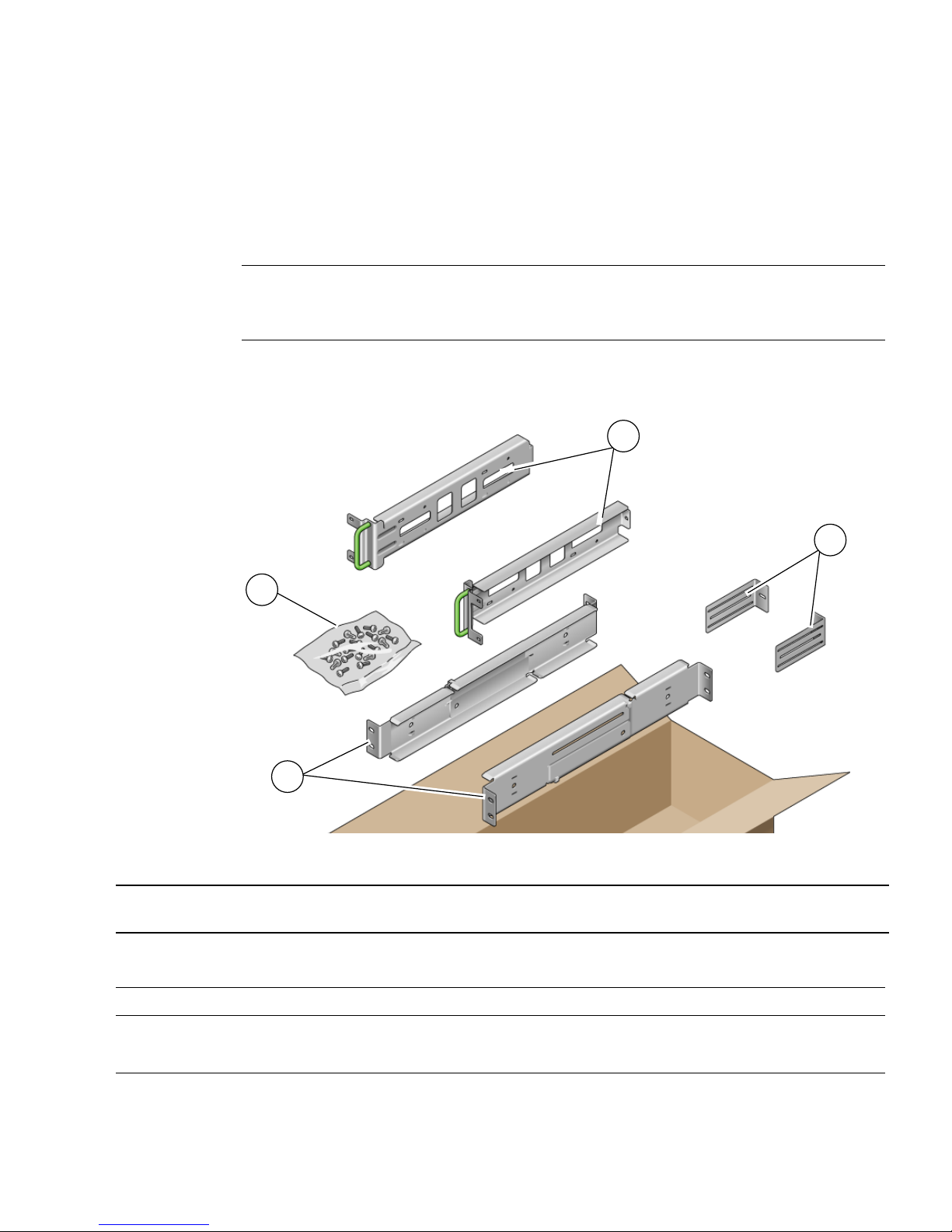
The hardmount kit for a 19-inch 4-post rack consists of:
■ Two hardmount brackets
22 Sun Netra T5220 Installation Guide • November 2011

■ Two rear mount support brackets
■ Two rear mount flanges
■ Bag of screws
Note – The front-to-back rail spacing must be at least 460 mm (18.11 in.) and not
more than 715 mm (28.15 in.) from the outside face of the front rail to the outside
face of the back rail.
FIGURE 3-1 Contents of the Hardmount 19-Inch 4-Post Kit
3
2
4
1
Figure Legend
1 Rear mount flanges 3 Rear mount support brackets
2 Screws 4 Hardmount brackets
TABLE 3-2 19-inch 4-Post Rackmount Screw Kit Contents
Number Description Where Used
10 M5 x 4.5 mm Phillips flathead screws 8 for hardmount brackets, 2 extra
10 M4 x 0.5 mm x 5 mm Phillips panhead screws 4-6 for rear mount brackets, 6-4 extra
10 M5 x 12.7 mm screws 10 for rack, if appropriate
Chapter 3 Mounting the Server Into a 4-Post Rack 23

TABLE 3-2 19-inch 4-Post Rackmount Screw Kit Contents (Continued)
Number Description Where Used
10 M6 x 13 mm screws 10 for rack, if appropriate
9 M6 square clip nuts 9 for rack, if appropriate
12 10-32 x 0.5 in. combo head screws 12 for rack, if appropriate
12 12-24 x 0.5 in. combo head screws 12 for rack, if appropriate
1. Get the hardmount brackets from the rack kit (FIGURE 3-1).
2. Use four of the supplied M5 × 4.5 mm flathead Phillips screws to secure each of
the hardmount brackets to the sides of the server (
FIGURE 3-2 Securing the Hardmount Brackets to the Server
FIGURE 3-2).
3. Measure the depth of the rack.
4. Get the two rear mount support brackets from the rack kit (
5. Install the rear mount support brackets at the rear of the server, extending the
rear mount support brackets to the measured depth of the rack (
Use two to three of the supplied M4 × 0.5 × 5 mm panhead Phillips screws for
each bracket, depending on the rack depth.
24 Sun Netra T5220 Installation Guide • November 2011
FIGURE 3-1).
FIGURE 3-2).

FIGURE 3-3 Attaching the Rear Mount Support Brackets
6. Lift the server to the desired location in the rack.
7. Using two screws per side, secure the front of the hardmount brackets attached
to the sides of the server to the front of the rack (
FIGURE 3-4).
FIGURE 3-4 Securing the Front of the Server to the Rack
8. Get the two rear mount flanges from the rack kit (FIGURE 3-1).
Chapter 3 Mounting the Server Into a 4-Post Rack 25

9. Using two screws for each rear mount support bracket, secure the rear mount
support brackets to the rear of the rack (
FIGURE 3-5 Securing the Rear of the Server to the Rack
FIGURE 3-5).
Mounting the Server in a Sliding Rail
Mount 19-Inch 4-Post Rack
▼ To Install a Server With a Sliding Rail Mount in
a 19-Inch 4-Post Rack
The sliding rail mount kit for a 19-inch 4-post rack consists of:
■ Two 19-inch 4-post Telco slide assemblies
■ Two short brackets
■ Two long brackets
■ Four M6 and four 10–32 threaded strips
■ Two extension brackets
■ Bag of screws
Note – The front-to-back rail spacing must be at least 392 mm (15.43 in.) and not
more than 863.6 mm (34 in.) from the outside face of the front rail to the outside face
of the back rail.
26 Sun Netra T5220 Installation Guide • November 2011

You also need the hardmount brackets from the standard rackmount kit that came
with the server (
FIGURE 3-6 Contents of the Sliding Rail 19-Inch 4-Post Kit
FIGURE 3-6).
5
4
3
2
1
Figure Legend
1 Long brackets 4 Screws
2 Short brackets 5 Telco slide assemblies
3 Threaded strips 6 Extension brackets
TABLE 3-3 Sliding Rail 19-inch 4-Post Rackmount Screw Kit Contents
Number Description Where Used
6
10 M4 x 0.5 mm x 5 mm Phillips panhead screws 8 for glides, 2 extra
10 M6 brass collar screws 4 for short brackets, 4 for long brackets, 2 extra
8 M5 panhead screws, nuts, plain washers and
star washers
8 for slides
Chapter 3 Mounting the Server Into a 4-Post Rack 27

TABLE 3-3 Sliding Rail 19-inch 4-Post Rackmount Screw Kit Contents (Continued)
Number Description Where Used
10 M5 x 12.7 mm screws 10 for rack, if appropriate
12 M6 x 13 mm screws 10 for rack, if appropriate
9 M6 square clip nuts 9 for rack, if appropriate
10 10–32 collar screws 4 short, 4 long, 2 extra 8 for racks with 10-32 holes, if appropriate
12 10-32 x 0.5 in. combo head screws 12 for rack, if appropriate
12 12-24 x 0.5 in. combo head screws 12 for rack, if appropriate
1. Get the hardmount brackets and M5 × 4.5 mm flathead Phillips screws from the
standard rack kit (
FIGURE 3-1).
These hardmount brackets and screws are shipped with the standard server ship
kit, not as part of the sliding rail 19-inch 4-post rackmount ship kit.
2. Use four of the supplied M5 × 4.5 mm flathead Phillips screws to secure each of
the hardmount brackets to the sides of the server (
FIGURE 3-7 Securing the Hardmount Bracket to the Server
FIGURE 3-7).
3. Get the Telco slide assemblies from the rack kit (FIGURE 3-6).
4. Press in the button on each slide and pull the glide completely out of the slide
(
FIGURE 3-8).
28 Sun Netra T5220 Installation Guide • November 2011

FIGURE 3-8 Dismantling the Slide
2
1
Figure Legend
1 Glide
2 Button
3 Slide (in two parts)
3
5. Using eight of the M4 × 0.5 × 5 mm panhead Phillips screws from the
rackmount kit (four for each side), screw each glide to the side of the server
chassis (
FIGURE 3-9 Fixing the Glides to the Server Chassis
FIGURE 3-9).
6. Get the short brackets and long brackets from the rackmount kit (FIGURE 3-6).
Chapter 3 Mounting the Server Into a 4-Post Rack 29

7. Lift each short bracket to the desired position at the front of the rack and attach
a short bracket to each of the front rack uprights (
FIGURE 3-10).
Use two of the brass M6 collar screws and M6 cage nuts (if required), and one
threaded strip, to secure each bracket (
FIGURE 3-10).
8. Lift each long bracket to the desired position at the rear of the rack and attach a
long bracket to each of the rear rack uprights (
FIGURE 3-10).
To secure each bracket, use two of the brass M6 collar screws and M6 cage nuts (if
required) and one threaded strip, exactly as you did for the front rack uprights in
the previous step.
FIGURE 3-10 Securing the Brackets to the Rack
Note – If your rack has 10–32 holes, use the 10–32 collar screws and 10–32 threaded
strips.
9. Extend a slide to line up the access holes with the front screw holes.
10. Secure the slide onto the short and long brackets at the front and rear of the
rack (
FIGURE 3-11).
Use the M5 panhead screws from the inside. Use the M5 nuts, plain washers, and
star washers from the outside. Use extension brackets instead of the long brackets
if the dimension is greater than 665 mm
30 Sun Netra T5220 Installation Guide • November 2011
.

FIGURE 3-11 Securing the Slide to the Brackets
Figure Legend
1 Short bracket
2 Slide
3 Long bracket
11. Repeat Step 9 and Step 10 for the slide on the other side of the rack.
12. Push the slides completely into the assembly on each side of the rack and
release the stop catches.
13. Align the glides attached to the server with the slide assemblies in the rack.
You might find that there is too much or too little room between the two slides
mounted in the rack. Consequently the glides attached to the server might not
align correctly with the slides in the rack. If either situation occurs, loosen the M6
collar screws and cage nuts on the long and short brackets (Step 7 and Step 8),
move them inward or outward to the appropriate points, then tighten them again.
14. Push in the slide buttons and slide the server all the way into the rack
enclosure (
FIGURE 3-12).
Chapter 3 Mounting the Server Into a 4-Post Rack 31

FIGURE 3-12 Sliding the Server Into the Rack
15. Using two screws per side, secure the front of the hardmount brackets that are
attached to the sides of the server to the front of the rack (
The size of the screws varies, depending on your particular rack.
FIGURE 3-13 Securing the Front of the Server to the Rack
FIGURE 3-13).
Hardmounting the Server in a 600-mm 4Post Rack
▼ To Install a Server With a Hardmount in a 600-
mm 4-Post Rack
The hardmount kit for a 600 mm 4-post rack consists of:
32 Sun Netra T5220 Installation Guide • November 2011
■ Two adjustable rails
■ Two side rails
■ Two rear flanges
■ Bag of screws
Note – The front-to-back rail spacing must be at least 392 mm (15.43 in.) and not
more than 504 mm (19.84 in.) from the outside face of the front rail to the outside
face of the back rail.
FIGURE 3-14 Contents of the Hardmount 600-mm 4-Post Kit
3
4
2
1
Figure Legend
1 Adjustable rails 3 Side rails
2 Screws 4 Rear flanges
TABLE 3-4 Hardmount 600 mm 4-Post Rackmount Screw Kit Contents
Number Description Where Used
12 M5 x 7 SEM screws 8 for side rails, 4 for rear flanges
10 M5 x 12.7 mm screws 10 for rack, if appropriate
Chapter 3 Mounting the Server Into a 4-Post Rack 33

TABLE 3-4 Hardmount 600 mm 4-Post Rackmount Screw Kit Contents (Continued)
Number Description Where Used
10 M6 x 13 mm screws 10 for rack, if appropriate
9 M6 square clip nuts 9 for rack, if appropriate
12 10-32 x 0.5 in. combo head screws 12 for rack, if appropriate
12 12-24 x 0.5 in. combo head screws 12 for rack, if appropriate
1. Get the adjustable rails from the rack kit (FIGURE 3-14).
2. Loosen the two screws at the middle of each adjustable rail so that you can
extend the adjustable rail (
FIGURE 3-15 Adjustable Rail Screws
FIGURE 3-15).
3. Lift one of the adjustable rails to the desired location in the rack. Using two
screws, secure the front of the rail in the rack (
The size of the screws varies, depending on your particular rack.
34 Sun Netra T5220 Installation Guide • November 2011
Adjustable rail screws
FIGURE 3-16).

FIGURE 3-16 Securing the Front of the Adjustable Rails to the Rack
4. At the rear of the rack, use two screws to secure the rear of the adjustable rails
to the rack (
FIGURE 3-17).
The size of the screws varies, depending on your particular rack.
FIGURE 3-17 Securing the Rear of the Adjustable Rails to the Rack
5. Tighten the two screws at the middle of each adjustable rail (FIGURE 3-15).
Chapter 3 Mounting the Server Into a 4-Post Rack 35

6. Repeat Step 3 through Step 5 to mount the other adjustable rail into the rack.
7. Get the rear flanges from the rack kit (
FIGURE 3-14).
8. Using one M5 × 7 SEM screw for each rear flange, loosely install the rear flange
onto the rear of each of the adjustable rails (
FIGURE 3-18).
Do not completely secure the rear flanges to the adjustable rails. You will use
these flanges to set the rack depth for the server in a later step.
FIGURE 3-18 Installing the Rear Flange Onto the Adjustable Rail
9. Get the side rails from the rack kit (FIGURE 3-14).
10. Using eight of the M5 × 7 SEM screws (four for each side rail), secure the side
rails to the sides of the server (
The side rails can accommodate rack rail setbacks (the distance from the front of
the rack to the rack rail) of 50 mm, 75 mm, or 100 mm, depending on the type of
rack you are installing the server into.
36 Sun Netra T5220 Installation Guide • November 2011
FIGURE 3-19).

FIGURE 3-19 Securing the Side Rails to the Server
11. Lift the server into the rack and slide the server onto the adjustable rails
(
FIGURE 3-20).
FIGURE 3-20 Sliding the Server Onto the Adjustable Rails
12. Push the server to the desired depth in the rack, then go to the rear of the server
and push the rear flanges flush against the back of the server (
If the rack is especially shallow, you can flip the rear flanges around so that they
rest flush against the rear of the server.
13. Lift the server out of the rack.
14. Set the rear flanges to the desired depth in the rack, then tighten the single M5
× 7 SEM screw on each of the flanges to secure them to the adjustable rails
(
FIGURE 3-18).
15. Lift the server into the rack and slide it onto the adjustable rails.
FIGURE 3-18).
Chapter 3 Mounting the Server Into a 4-Post Rack 37

16. Push the server backward until it rests flush against the rear flanges, then use
one M5 × 7 SEM screw for each rear flange to secure the rear of the server to the
rear flanges (
FIGURE 3-21 Securing the Rear of the Server to the Rear Flanges
FIGURE 3-21).
17. At the front of the rack, use two screws per side to secure the side rails that are
attached to the server to the front of the rack (
FIGURE 3-22).
The size of the screws varies, depending on your particular rack.
FIGURE 3-22 Securing the Front of the Server to the Front of the Rack
38 Sun Netra T5220 Installation Guide • November 2011

Chapter 3 Mounting the Server Into a 4-Post Rack 39

40 Sun Netra T5220 Installation Guide • November 2011

CHAPTER
4
Mounting the Server Into a 2-Post
Rack
This chapter provides instructions for installing the server in an open 2-post rack.
Note – The server ships with a 19-inch, 4-post hardmount rack kit. The rack rail kits
described in this chapter must be ordered separately from Sun.
This chapter contains the following sections:
■ “2-Post Rackmounting Options” on page 42
■ “Hardmounting the Server in a 23-Inch 2-Post Rack” on page 43
■ “Hardmounting the Server in a 19-Inch 2-Post Rack” on page 48
■ “Mounting the Server With a Sliding Rail Mount in a 19-Inch 2-Post Rack” on
page 54
Note – References to left and right are from your viewpoint as you face either the
front or rear of the equipment.
Caution – The server is heavy. Two people are required to lift and mount the server
into a rack enclosure when following the procedures in this chapter.
41

Tip – The Sun Netra T5220 server mounted in a 2-post rack with the 19-inch, 2 post
mounting kit (X7901A-4) protrudes 193 millimeters (7.59 inches) beyond the front of
the rack rail post.
For less protrusion in the front of the rack, the server can also be mounted using the
rear portion of the rail, which reduces protrusion to 115 millimeters (4.52 inches)
beyond the front of the rack rail post.
2-Post Rackmounting Options
The server ships with a 19-inch, 4-post hardmount rack kit (see “Hardmounting the
Server in a 19-Inch 4-Post Rack” on page 22 for installation instructions).
lists two additional 2-post rackmount kit options that can be ordered from Sun. This
chapter provides installation instructions for these rackmount kit options.
TABLE 4-1 Optional Rackmount Kits
Mounting Kit Installation Instructions
TABLE 4-1
23-inch 2-post rackmount kit “To Install a Server With a Hardmount in a 23-Inch 2-
Post Rack” on page 43
19-inch 2-post rackmount kit “To Install a Server With a Hardmount in a 19-Inch 2-
Post Rack” on page 48
19-inch 2-post slide rackmount kit “To Install a Server With a Sliding Rail Mount in a 19-
Inch 2-Post Rack” on page 54
Note – If you have more than six DC-powered servers in the same rack, you might
exceed Telcordia NEBS EMI limits.
42 Sun Netra T5220 Installation Guide • November 2011

Hardmounting the Server in a 23-Inch 2Post Rack
▼ To Install a Server With a Hardmount in a 23-
Inch 2-Post Rack
The hardmount kit for a 23-inch 2-post rack consists of:
■ Two side brackets
■ Two rail guides
■ Two rear plates
■ Bag of screws
Note – The 23-inch 2-post rackmount kit supports rack web thicknesses (the width
of the rack post) of 76.20 mm (3 in.), 101.6 mm (4 in.), and 127 mm (5 in.).
FIGURE 4-1 Contents of the Hardmount 23-Inch 2-Post Kit
3
4
2
1
Chapter 4 Mounting the Server Into a 2-Post Rack 43

Figure Legend
1 Side brackets 3 Rear plates
2 Screws 4 Rail guides
TABLE 4-2 Hardmount 23-Inch 2-Post Rackmount Screw Kit Contents
Number Description Where Used
10 M5 x 7 SEM screws 8 for side brackets, 2 for rear plates
10 M5 x 12.7 mm screws 10 for rack, if appropriate
10 M6 x 13 mm screws 10 for rack, if appropriate
9 M6 square clip nuts 9 for rack, if appropriate
12 10-32 x 0.5 in. combo head screws 12 for rack, if appropriate
12 12-24 x 0.5 in. combo head screws 12 for rack, if appropriate
1. Get the side brackets from the rack kit (FIGURE 4-1).
2. Using eight of the M5 × 7 SEM screws (four for each side bracket), secure the
side brackets to the sides of the server (
FIGURE 4-2).
FIGURE 4-2 Securing the Side Brackets to the Side of the Server
3. Get the rail guides from the rack kit (FIGURE 4-1).
44 Sun Netra T5220 Installation Guide • November 2011

4. Lift the rail guides to the desired height in the rack and, using two screws each,
secure both rail guides to the rack (
FIGURE 4-3).
The size of the screws varies, depending on your particular rack.
FIGURE 4-3 Installing the Rail Guides in the Rack
5. Lift the server into the rack and slide it onto the rail guides (FIGURE 4-4).
Chapter 4 Mounting the Server Into a 2-Post Rack 45

FIGURE 4-4 Installing and Securing the Server in the 2-Post Rack
6. Using two screws on each side, secure each side bracket on the server to the
front of the rack (
FIGURE 4-4).
The size of the screws varies, depending on your particular rack.
7. (Optional) If your environment contains especially high vibrations, use the rear
plates to further secure the server to the rack (
FIGURE 4-1).
The rear plates attach to the rear of the post and to one of the three eyelets on
each side bracket, depending on the thickness of the post.
a. Using one M5 × 7 SEM screw for each rear plate, loosely install the screw in
one of the three positions on the rear plate (
FIGURE 4-5).
The position varies depending on the thickness of the rail in the rack. For
example,
FIGURE 4-5 shows where you would install the screw for the middle
rack position on the rear plate.
46 Sun Netra T5220 Installation Guide • November 2011

FIGURE 4-5 Installing a Screw on the Middle Rack Position on the Rear Plate
b. Slide the rear plate in so that the screw slides into position into one of the
eyelets.
The screw head should be facing the rear of the server and the other side of the
rear plate should be in front of the rack post (
FIGURE 4-6 Installing the Rear Plate to the Side Bracket
FIGURE 4-6).
c. Tighten the screw to secure the rear plate to the eyelet on the side bracket
(
FIGURE 4-6).
d. Using two screws, secure the other side of the rear plate to the back of the
post (
FIGURE 4-7).
Chapter 4 Mounting the Server Into a 2-Post Rack 47

FIGURE 4-7 Securing the Rear Plate to the Back of the Post
The size of the screws varies, depending on your rack.
e. Repeat Step a through Step d to secure the rear plate on the other post.
Hardmounting the Server in a 19-Inch 2Post Rack
▼ To Install a Server With a Hardmount in a 19-
Inch 2-Post Rack
The hardmount kit for a 19-inch 2-post rack consists of:
■ Two side brackets
■ Two rear plates
■ Bag of screws
48 Sun Netra T5220 Installation Guide • November 2011

Note – The 19-inch 2-post rackmount kit supports rack web thicknesses (the width
of the rack post) of 76.20 mm (3 in.), 101.6 mm (4 in.), and 127 mm (5 in.).
FIGURE 4-8 Contents of the Hardmount 19-Inch 2-Post Kit
2
3
1
Figure Legend
1 Rear plates 3 Side brackets
2 Screws
TABLE 4-3 Hardmount 19-Inch 2-Post Rackmount Screw Kit Contents
Number Description Where Used
10 M5 x 7 SEM screws 8 for side brackets, 2 extra
6 M3 x 8 SEM screws 4 for rear plates, 2 extra
10 M5 x 12.7 mm screws 10 for rack, if appropriate
10 M6 x 13 mm screws 10 for rack, if appropriate
9 M6 square clip nuts 9 for rack, if appropriate
12 10-32 x 0.5 in. combo head screws 12 for rack, if appropriate
12 12-24 x 0.5 in. combo head screws 12 for rack, if appropriate
1. Get the side brackets from the rack kit (FIGURE 4-8).
2. Using four of the M5 × 7 SEM screws for each side bracket, secure the side
brackets to the sides of the server (
FIGURE 4-9).
Chapter 4 Mounting the Server Into a 2-Post Rack 49

FIGURE 4-9 Securing the Side Brackets to the Side of the Server
3. Lift the server into the rack.
4. Using two screws for each bracket, secure the front of the server to the front of
the rack (
FIGURE 4-10).
The size of the screws varies, depending on your rack.
FIGURE 4-10 Installing and Securing the Server in the 2-Post Rack
5. (Optional) If your environment contains especially high vibrations, use the rear
plates to further secure the server to the rack (
FIGURE 4-8).
The rear plates attach to the rear of the post and to one of the three sets of eyelets
on each side bracket, depending on the thickness of the post.
50 Sun Netra T5220 Installation Guide • November 2011

a. Using two of the M3 × 8 SEM screws for each rear plate, loosely install the
screws in one of the six positions on the rear plate (
FIGURE 4-11).
The position varies depending on the thickness of the rail in the rack. For
example,
FIGURE 4-11 shows where you would install the screws for the
optimum rack position on the rear plate.
FIGURE 4-11 Installing Screws on the Optimum Rack Position on the Rear Plate
b. Slide the rear plate in so that the screws slide into position into one set of
the eyelets.
The screw heads should be facing the rear of the server and the other side of
the rear plate should be in front of the rack post (
FIGURE 4-12).
Chapter 4 Mounting the Server Into a 2-Post Rack 51

FIGURE 4-12 Installing the Rear Plate to the Side Bracket
c. Tighten the screws to secure the rear plate to the set of eyelets on the side
bracket (
FIGURE 4-12).
d. Using two screws, secure the other side of the rear plate to the back of the
post (
FIGURE 4-13).
The size of the screws varies, depending on your rack.
52 Sun Netra T5220 Installation Guide • November 2011

FIGURE 4-13 Securing the Rear Plate to the Rack
e. Repeat Step a through Step d to secure the rear plate on the other post.
Mounting the Server With a Sliding Rail
Mount in a 19-Inch 2-Post Rack
▼ To Install a Server With a Sliding Rail Mount in
a 19-Inch 2-Post Rack
The sliding rail mount kit for a 19-inch 2-post rack consists of:
■ Two 19-inch 2-post Telco slide assemblies
■ Two short brackets
■ Two long brackets
■ Four M4 and four 10-32 threaded strips
■ Two extension brackets
Chapter 4 Mounting the Server Into a 2-Post Rack 53

■ Bag of screws
Note – The 19-inch 2-post sliding rail rackmount kit supports rack web thicknesses
(the width of the rack post) of 76.20 mm (3 in.), 101.6 mm (4 in.), and 127 mm (5 in.).
Note – The front-to-back rail spacing must be at least 392 mm (15.43 in.) and not
more than 863.6 mm (34 in.) from the outside face of the front rail to the outside face
of the back rail.
FIGURE 4-14 Contents of the Sliding Rail 19-Inch 2-Post Kit
54 Sun Netra T5220 Installation Guide • November 2011

Figure Legend
1 Screws 4 Right side inner member
2 Left side inner member 5 Right side assembly
3 Left side assembly
TABLE 4-4 Sliding Rail 19-Inch 4-Post Rackmount Screw Kit Contents
Number Description Where Used
10 M4 x 0.5 mm x 5 mm Phillips panhead screws 8 for glides, 2 extra
10 M5 x 12.7 mm screws 10 for rack, if appropriate
12 M6 x 13 mm screws 10 for rack, 2 extra
9 M6 square clip nuts 9 for rack, if appropriate
10 10–32 collar screws, 4 short, 4 long, 2 extra 8 for racks with 10-32 holes, if appropriate
12 10–32 x 0.5 in. combo head screws 12 for rack, if appropriate
12 12–24 x 0.5 in. combo head screws 12 for rack, if appropriate
1. Obtain the slide assemblies from the rack kit (FIGURE 4-14).
2. Press in the green button on each slide assembly and pull the right side and
left side inner members (glides) completely out of the slides (
FIGURE 4-15 Removing Glides from the Slides
FIGURE 4-15).
1
3
2
Chapter 4 Mounting the Server Into a 2-Post Rack 55

Figure Legend
1 Button
2 Glide
3 Slide (in two parts)
3. Using eight of the M4 x 0.5 x 5 mm Phillips panhead screws from the
rackmount kit (four for each side), attach each glide to the side of the server
chassis (
FIGURE 4-16 Attaching the Glides to the Server Chassis
FIGURE 4-16).
4. Get the rack brackets (front and rear) from the rackmount kit (FIGURE 4-14).
56 Sun Netra T5220 Installation Guide • November 2011

5. Lift each front bracket to the desired position at the front of the rack, and attach
a front bracket to each of the front rack posts (
FIGURE 4-18).
To secure each bracket, use two of the M5 x 12.7 mm screws or two of the
M6 x 13 mm screws. Tighten the screws enough to secure the brackets, but leave
them loose enough for adjustment later.
FIGURE 4-17 Attaching the Front Brackets to the Posts
Chapter 4 Mounting the Server Into a 2-Post Rack 57

6. Lift each rear bracket to the desired position at the rear of the rack, and attach a
rear bracket to each of the rear rack posts (
FIGURE 4-18).
To secure each bracket, use two of the M5 x 12.7 mm screws or two of the M6 x 13
mm screws, as you did in Step 5. Tighten the screws enough to secure the
brackets, but leave them loose enough for adjustment later.
FIGURE 4-18 Securing the Rear Brackets to the Rack Posts
Note – If your rack has 10–32 holes, use the 10–32 collar screws and 10–32 threaded
strips.
58 Sun Netra T5220 Installation Guide • November 2011

7. Align the glides attached to the server with the slide assemblies in the rack.
You might find that there is too much or too little room between the two slides
mounted in the rack, consequently the glides attached to the server might not
align correctly with the slides in the rack. If either situation occurs, loosen the
screws on the front and back brackets (Step 5 and Step 6), move the brackets
inward or outward to the appropriate points, then tighten the brackets again.
8. Push in the slide buttons and slide the server all the way into the rack
enclosure (
FIGURE 4-19 Sliding the Server Into the Rack
FIGURE 4-19).
Chapter 4 Mounting the Server Into a 2-Post Rack 59

9. Fully tighten the screws on the front and rear brackets.
FIGURE 4-20 Tightening the Front Bracket Screws
60 Sun Netra T5220 Installation Guide • November 2011

FIGURE 4-21 Tightening the Rear Bracket Screws
Chapter 4 Mounting the Server Into a 2-Post Rack 61

10. Attach Cable Management Arm (CMA) to rails (note labels on rails and CMA)
to right (
FIGURE 4-22) side.
Side with arrow attaches to inner glide; other side attached to outer member.
FIGURE 4-22 Attaching Cable Management Arm to Right Side
62 Sun Netra T5220 Installation Guide • November 2011

11. Attach CMA to rails (note labels on rails and CMA) to left (FIGURE 4-23) side.
Side with arrow attaches to inner glide; other side attached to outer member.
FIGURE 4-23 Attaching Cable Management Arm to Left Side
Chapter 4 Mounting the Server Into a 2-Post Rack 63

64 Sun Netra T5220 Installation Guide • November 2011

CHAPTER
5
Cabling the Server
This chapter provides instructions for cabling the server. Topics include:
■ “Cable Connections and Ports” on page 65
■ “Connecting the Server Cables” on page 69
■ “DC Operation Conditions and Procedures” on page 73
Note – Both AC and DC versions of the server must be installed in a restricted-
access location.
Caution – The Sun Netra T5220 must not be directly connected to Outside Plant
cables.
Cable Connections and Ports
The following list describes the server’s cable connections and ports:
■ Minimum cable connections for the servers:
■ At least one system on-board Ethernet network connection (NET port)
■ The service processor serial management port (SER MGT port)
■ The service processor network management port (NET MGT port)
■ AC or DC power cables for the two system power supplies
■ Service processor management ports: There are two serial management ports for
use with the ILOM system controller.
65

■ The service processor serial management port (labeled SER MGT) uses an RJ-
45 cable and is always available. This is the default connection to the ILOM
system controller.
■ The service processor network management port (labeled NET MGT) is the
optional connection to the ILOM system controller. This port is not available
until you have configured network settings for the system controller (through
the service processor serial management port). See “Enabling the Service
Processor Network Management Port” on page 83. The service processor
network management port uses an RJ-45 cable for a 10/100BASE-T connection.
This port does not support connections to Gigabit networks.
■ Ethernet ports: Labeled NET0, NET1, NET2, and NET3. The Ethernet interfaces
operate at 10 Mbps, 100 Mbps, and 1000 Mbps. The transfer rates for the Ethernet
ports are given in
TABLE 5-1 Ethernet Connection Transfer Rates
Connection Type IEEE Terminology Transfer Rate
Ethernet 10BASE-T 10 Mbit/sec
Fast Ethernet 100BASE-TX 100 Mbits/sec
Gigabit Ethernet 1000BASE-T 1000 Mbit/sec
TABLE 5-1.
■ TTYA serial port: The TTYA serial port has a DB-9 connector, which is located at
the lower right corner of the rear panel (
FIGURE 5-1). A DB-9 to RJ-45 adapter cable
is included in the shipping kit.
■ Use the DB-9 connector with a null modem cable for serial devices. This port
appears as ttya in Solaris OS and OpenBoot™ messages.
■ This port is not connected to the service processor serial management port.
■ Use this serial port only for general purpose serial data transfers.
■ Use a null modem cable or an adapter to perform the crossovers given for each
connector.
■ USB Ports: Two Universal Serial Bus (USB) ports labeled USB 0 and USB 1 are
provided on the rear panel (
FIGURE 5-1 ). USB ports support hot-plugging. You can
connect and disconnect USB cables and peripheral devices while the server is
running, without affecting system operations.
■ You can only perform USB hot-plug operations while the OS is running. USB
hot-plug operations are not supported when the OpenBoot PROM ok prompt
is displayed or before the system has completed booting.
■ You can connect up to 126 devices to each of the two USB controllers, for a
total of 252 USB devices per server.
■ Input AC/DC power cables: Do not attach power cables to the power supplies
until you have finished connecting the data cables, and have connected the server
to a serial terminal or a terminal emulator (PC or workstation). The server goes
66 Sun Netra T5220 Installation Guide • November 2011

into Standby mode and the ILOM system controller initializes as soon as the
input power cables are connected to the power source. System messages might be
lost if the server is not connected to a terminal, PC, or workstation at this time.
Connector Locations
FIGURE 5-1 shows the connectors on the rear panel of the Sun Netra T5220 server.
FIGURE 5-1 Rear Panel Connectors and Features on the Sun Netra T5220 Server
15 16 19
2 4 5
31 9
Figure Legend
1 Power Supply 0 LEDs top to bottom: Locator LED Button, Service Required LED, Power OK LED
2 Power Supply 0
3 Power Supply 1 LEDs top to bottom: Locator LED Button, Service Required LED, Power OK LED
4 Power Supply 1
5 Captive screw for securing motherboard (1 of 2)
6 System LEDs left to right: Locator LED Button, Service Required LED, Power OK LED
7 Service Processor Serial Management Port
8 Service Processor Network Management Port
9 Captive screws for securing the bottom PCI cards. Each bottom card has screws on both sides
10 Gigabit Ethernet Ports left to right: NET0, NET1, NET2, NET3
11 Alarm Port
12 USB ports left to right: USB0, USB1
13 TTYA Serial Port
14 Captive screw for securing motherboard (2 of 2)
15 PCI-X Slot 3
7 8
6
17 18
10
11 14
12 13
20
Chapter 5 Cabling the Server 67

Figure Legend
16 PCIe or XAUI Slot 0
17 PCI-X Slot 4
18 PCIe or XAUI Slot 1
19 PCIe Slot 5
20 PCIe Slot 2
Status Indicator Locations
FIGURE 5-2 shows the status indicators on the front panel of the Sun Netra T5220
server.
FIGURE 5-2 Location of the Bezel Server Status and Alarm Status Indicators
4
3
2
1
Figure Legend
65
7
8
1 User (amber) Alarm Status Indicator 5 Locator LED
2 Minor (amber) Alarm Status Indicator 6 Fault LED
3 Major (red) Alarm Status Indicator 7 Activity LED
4 Critical (red) Alarm Status Indicator 8 Power LED
68 Sun Netra T5220 Installation Guide • November 2011

TABLE 5-2 Bezel Server Status Indicators
Indicator LED Color LED State Component Status
Locator White On Server is identified with the superuser
locator or ILOM setlocator command.
Off Normal state
Fault Amber On The server has detected a problem and
requires the attention of service personnel.
Off The server has no detected faults.
Activity Green On The server is powered up and running the
Solaris Operating System.
Off Either power is not present or the Solaris
software is not running.
Connecting the Server Cables
To boot the server, you must connect and configure the network and serial ports. The
procedures are given in the following sections.
■ “To Connect the Service Processor Serial Management Port” on page 70
■ “To Connect the Service Processor Network Management Port” on page 71
■ “To Connect the Ethernet Network Cables” on page 71
■ “To Connect AC Power Cables to the Server” on page 72
The server also has serial and USB ports available for connections to optional
devices (see “Cable Connections and Ports” on page 65).
Note – When you are finished connecting the cables to the server, ensure that the
server can slide smoothly in and out of the rack without binding or damaging the
cables.
▼ To Connect the Service Processor Serial
Management Port
The service processor serial management port is marked SER MGT (FIGURE 5-3). It is
the leftmost RJ-45 port on the rear panel.
Chapter 5 Cabling the Server 69

Note – The cable and DB-9 RJ-45 adapters are for the host serial port, and not for
the server SER MGT port.
FIGURE 5-3 Service Processor Serial Management Port – Rear Panel
Use this port for server management. This port is needed to set up the service
processor network management port, as detailed in “Enabling the Service Processor
Network Management Port” on page 83.
Note – Use the service processor serial management port only for server
management. It is the default connection between the service processor and a
terminal or a computer.
Caution – Do not attach a modem to this port.
● Connect a Category 5 cable from the SER MGT serial management port to the
terminal device.
When connecting either a DB-9 or a DB-25 cable, use an adapter to perform the
crossovers given for each connector.
▼ To Connect the Service Processor Network
Management Port
The service processor network management port is labeled NET MGT (FIGURE 5-4). It
is located just to the right of the serial management (SER MGT) port on the rear
panel.
70 Sun Netra T5220 Installation Guide • November 2011

FIGURE 5-4 Service Processor Network Management Port – Rear Panel
Note – This port is not operational until you configure the network settings
(through the serial managment port), as detailed in “Configuring the Service
Processor Network Management Port” on page 86.
Note – If you have access to a DHCP server on the network, you can see the service
processor get an IP address because the DHCP client is enabled by default.
Note – The service processor network management port is configured by default to
retrieve network settings with Dynamic Host Configuration Protocol (DHCP) and
allow connections using Solaris Secure Shell (SSH). You might need to modify these
settings for your network. Instructions are given in Chapter 6.
● Connect a Category 5 cable from the NET MGT network management port to
your network switch or hub.
▼ To Connect the Ethernet Network Cables
The server has four network connectors, marked NET0, NET1, NET2, and NET3
(
FIGURE 5-5). These connectors are RJ-45 Gigabit Ethernet.
FIGURE 5-5 Service Processor Ethernet Network Ports – Rear Panel
Chapter 5 Cabling the Server 71

1. Connect a Category 5 cable from your network switch or hub to Ethernet Port 0
(NET0) on the rear of the chassis.
NET0 is the farthest left port in the 4-port network cluster in
2. Connect Category 5 cables from your network switch or hub to the remaining
Ethernet ports (NET1, NET2, NET3), as needed.
Note – The LEDs located above each NET port are Link/Activity (left) and Speed
(right) indicators for each port.
FIGURE 5-5.
▼ To Connect AC Power Cables to the Server
Powering on the system for the first time requires special preparation and
procedures. For example, if you have not prepared a display before connecting the
AC power cable, system messages might be lost.
Caution – Finish the hardware procedures in this chapter, but do not attach the AC
power cable yet.
Powering on the system for the first time requires special preparation and
procedures. For example, if you have not prepared a display before connecting the
AC power cable, system messages could be missed.
Caution – The server goes into Standby mode and the service processor initializes
as soon as the AC power cable is connected to the power source.
● Go to “Powering On the System for the First Time” on page 79 for instructions
on connecting the server to AC power.
DC Operation Conditions and
Procedures
This section provides DC power cabling and requirements information.
72 Sun Netra T5220 Installation Guide • November 2011

DC Power Source Requirements
TABLE 5-3 lists DC power source requirements for each power supply in the Sun
Netra T5220 server, and
as a whole.
TABLE 5-3 DC Operating Power Limits and Ranges for Each Power Supply in the Server
Description Limit or Range
Operating input voltage range -40 VDC to -75 VDC nominal
Maximum operating input current 11.7 A
Maximum operating input power 660 W
TABLE 5-4 DC Operating Power Limits and Ranges for the Server
Description Limit or Range
Operating input voltage range -40 VDC to -75 VDC
Maximum operating input current 23 A
TABLE 5-4 lists DC power source requirements for the server
Maximum operating input power 900 W
The server must meet the following:
■ Must be reliably connected to protected earth ground
■ May be supplied by one or two power sources, isolated from each other
■ Must be capable of providing up to 500 W of continuous power per power supply
■ Limited to TNV-2 as defined by UL 60950 and IEC 60950
Note – The DC version of the server must be installed in a restricted-access location.
According to the intent of the National Electrical Code, a restricted-access location is
an area intended for qualified or trained personnel only and has access controlled by
a locking mechanism, such as a key lock or an access card system.
DC Supply and Ground Conductor Requirements
The server must meet the following:
■ Suitable conductor material: use copper conductors only
Chapter 5 Cabling the Server 73

■ Power supply connections through the input connector: 12 AWG (between the
Sun Netra T5220 server and the source). There are three conductors:
■ -48V (negative terminal)
■ Chassis ground connection
■ -48V Return (positive terminal)
■ System ground conductor: 12 AWG (to be connected to the chassis)
■ Cable insulation rating: Minimum of 75˚C (167˚F), low smoke fume (LSF), flame
retardant
■ Cable type one of the following:
■ UL style 1028 or other UL 1581 (VW-1) compliant equivalent
■ IEEE 383 compliant
■ IEEE 1202-1991 compliant
■ Branch circuit cable insulation color: Per applicable National Electrical Codes
■ Grounding cable insulation color: Green/yellow
Note – Depending on the DC power source, the -48V (negative terminal) might be
marked with a minus (-) symbol, and the -48V Return (positive terminal) might be
marked with a positive (+) symbol.
When attaching DC cables, keep the following requirement in mind:
Caution – You must restrict the connection of the Sun Netra T5220 server to the DC
power source to minimize the possibility that transient energy will appear on the
main input to the equipment. The DC battery power source must be in the same
premises as the server. The server cannot be in one building with the power source
in another building.
Overcurrent Protection Requirements
■ Overcurrent protection devices must be provided as part of each equipment rack.
■ Circuit breakers must be located between the DC power source and the Sun Netra
T5220 server. Use one 20 A double-pole, fast trip DC-rated circuit breaker for each
power supply unit.
Note – Overcurrent protection devices must meet applicable national and local
electrical safety codes and be approved for the intended application.
74 Sun Netra T5220 Installation Guide • November 2011

▼ To Assemble the DC Input Power Cable
1. Identify the parts that you will use to assemble the DC input power cable
(
FIGURE 5-6).
The following DC connection parts are required to assemble one or more DC
power input cables. These cables connect the -48V DC input source(s) to the
power supply units.
■ DC input plugs
■ Cage clamp operating lever
■ Tie wraps
FIGURE 5-6 DC Connection Parts
21
Figure Legend
1 DC input plug
2 Cage clamp operating lever
2. Turn off power from the DC power source through the circuit breakers.
Caution – Do not proceed with these instructions until you have turned off the
power from the DC power source through the circuit breakers.
3. Get a DC input plug from the ship kit.
4. Locate the three wires coming from the DC power source that will be used in
the connection to your unit:
■ -48V (negative terminal)
■ Chassis ground
Chapter 5 Cabling the Server 75

■ -48V Return (positive terminal)
Note – Depending on the DC power source, the -48V (negative terminal) might be
marked with a minus (-) symbol, and the -48V Return (positive terminal) might be
marked with a positive (+) symbol.
5. Strip 5/16 inches (8 mm) of insulation from each of the wires coming from the
DC power source.
Do not strip more than 5/16 inches (8 mm) from each wire. Doing so leaves
uninsulated wire exposed from the DC connector after the assembly is complete.
FIGURE 5-7 Stripping the Insulation From the Wire
6. Open the cage clamp for this section of the DC input plug by taking one of the
following actions:
■ Insert the tip of the cage clamp operating lever into the rectangular hole directly
above the hole in the DC input plug where you want to insert the first wire. Press
down on the cage clamp operating lever (
■ Insert a small slotted screwdriver into the rectangular hole directly above the hole
FIGURE 5-8).
in the DC input plug where you want to insert the first wire, and press down on
the screwdriver (
FIGURE 5-9).
76 Sun Netra T5220 Installation Guide • November 2011

FIGURE 5-8 Opening the DC Input Plug Cage Clamp Using the Cage Clamp Operating
Lever
FIGURE 5-9 Opening the Cage Clamp Using a Screwdriver
Chapter 5 Cabling the Server 77

7. Feed the exposed section of the appropriate wire into the rectangular plug hole
in the DC input plug.
FIGURE 5-10 shows which wires should be inserted into each hole in the DC input
plug.
FIGURE 5-10 Assembling the DC Input Power Cable
Figure Legend
1 Top of connector 3 From chassis ground (green/yellow)
2 From -48V return 4 From -48V
8. Repeat Step 6 and Step 7 for the other two wires to complete the assembly of
the DC input power cable.
9. Repeat Step 4 through Step 8 to create as many DC input power cables as you
need for your unit.
You need two DC input power cables for each of the power supplies.
If you need to remove a wire from the DC input plug, insert the cage clamp
operating lever or a small screwdriver into the slot directly above the wire and
press down (
FIGURE 5-8 and FIGURE 5-9). Pull the wire from the DC input plug.
78 Sun Netra T5220 Installation Guide • November 2011

CHAPTER
6
Powering On the System
This chapter includes instructions for booting the server and for enabling the system
controller network management port.
The following topics are included:
■ “Powering On the System for the First Time” on page 79
■ “Enabling the Service Processor Network Management Port” on page 83
■ “Logging In To the Service Processor” on page 84
■ “Using the Service Processor for Common Operations” on page 90
■ “Booting the Solaris Operating System” on page 94
■ “Verifying System Functionality” on page 97
Powering On the System for the First
Time
This section provides an overview and instructions for powering on your system the
first time.
ILOM System Console
When you power on the system, the boot process begins under the control of the
Integrated Lights Out Manager (ILOM) system console. The system console displays
status and error messages generated by firmware-based tests during system startup.
79

Note – To see these status and error messages, connect a terminal or terminal
emulator to the serial management port (SERIAL MGT). For a basic procedure to
connect a terminal or terminal emulator, see “To Power On the System for the First
Time” on page 81.
For a more detailed discussion on configuring the system console and connecting
terminals, refer to the Sun Netra T5220 Server Administration Guide.
ILOM Service Processor
After the system console finishes its low-level system diagnostics, the ILOM service
processor initializes and runs a higher level of diagnostics. When you access the
ILOM service processor using a device connected to the serial management port, you
see the output of the ILOM diagnostics.
By default, the network management port is configured to automatically retrieve
network configuration using Dynamic Host Configuration Protocol (DHCP) and to
allow connections using Secure Shell (SSH).
Note – If you are unable to use DHCP and SSH on your network, you must connect
to the ILOM service processor using the serial management port to reconfigure the
network management port. See “Configuring the Service Processor Network
Management Port” on page 86.
Once the network management port (NET MGT) has been assigned an IP address,
you can connect to the ILOM service processor using SSH.
CLIs, User Accounts, and Passwords for
Connecting to the ILOM Service Processor
When connecting to the ILOM service processor for the first time using the serial or
network management ports, the default CLI is ILOM, the default user account is
root, and the default password is changeme. Examples in this document use the
default ILOM CLI.
ILOM also provides an Advanced Lights Out Management (ALOM) compatability
CLI that uses commands that resemble the ALOM CMT CLI commands. To access
the ALOM compatability CLI, you must first create an admin account with the role
of administrator. Once you create the admin account, assign the ALOM
80 Sun Netra T5220 Installation Guide • November 2011

compatability CLI as the default CLI (role=administrator, cli=alom). For more
information on using the ALOM compatability CLI, refer to the Integrated Lights Out
Management 2.0 (ILOM 2.0) Supplement for Sun Netra T5220 Server.
▼ To Power On the System for the First Time
Tip – The serial terminal or a terminal emulator should be connected before you
connect the power cables, or you will not see the system messages. The server goes
into Standby mode and the ILOM service processor initializes as soon as the AC
power cables are connected to the power source.
The service processor runs on the 3.3V standby voltage. As soon as AC power is
connected to the system, the service processor powers on, runs diagnostics, and
initializes the ILOM firmware.
1. Connect a terminal or a terminal emulator (PC or workstation) to the service
processor serial management port.
Configure the terminal or terminal emulator with these settings:
■ 9600 baud
■ 8 bits
■ No parity
■ 1 Stop bit
■ No handshake
Note – When you power on the server for the first time and you do not have a
terminal or terminal emulator (PC or workstation) connected to the service processor
serial management port, you will not see system messages. After connecting to the
server with a terminal or terminal emulator, log in to the ILOM CLI or the ALOM
compatability CLI to get to the service processor console.
2. Turn on the terminal or terminal emulator.
3. Connect the AC power cables to Power Supply 0 and Power Supply 1. Watch
the terminal for system messages.
Chapter 6 Powering On the System 81

FIGURE 6-1 Rear Panel Power Connectors of a Sun Netra T5220 Server
1 2
Figure Legend
1 Power Supply 0
2 Power Supply 1
After the service processor boots, the service processor login prompt is displayed on
the serial console. The following example shows a partial output from the service
processor boot sequence leading to the login prompt.
EXAMPLE 6-1 Sample Service Processor Output
U-Boot 1.1.1 (August 23 2007 - 21:30:12)
...
POST cpu PASSED
POST ethernet PASSED
Hit any key to stop autoboot: 0
## Booting image at fe080000 ...
IP Protocols: ICMP, UDP, TCP, IGMP
Checking all file systems...
fsck 1.37 (21-Mar-2005)
Setting kernel variables ...
... done.
Mounting local filesystems...
Cleaning /tmp /var/run /var/lock.
Identifying DOC Device Type(G3/G4/H3) ...
OK
Configuring network interfaces...Internet Systems Consortium DHCP
Client V3.0.1
Copyright 2007 Internet Systems Consortium.
All rights reserved.
82 Sun Netra T5220 Installation Guide • November 2011

EXAMPLE 6-1 Sample Service Processor Output (Continued)
For info, please visit http://www.isc.org/products/DHCP
eth0: config: auto-negotiation on, 100FDX, 100HDX, 10FDX, 10HDX.
Listening on LPF/eth0/00:14:4f:3f:8c:af
Sending on LPF/eth0/00:14:4f:3f:8c:af
Sending on Socket/fallback
DHCPDISCOVER on eth0 to 255.255.255.255 port 67 interval 6
eth0: link up, 100 Mbps Full Duplex, auto-negotiation complete.
DHCPDISCOVER on eth0 to 255.255.255.255 port 67 interval 15
Hostname: hostname.
Starting portmap daemon: portmap.
Initializing random number generator...done.
INIT: Entering runlevel: 3
Starting system log daemon: syslogd and klogd.
Starting periodic command scheduler: cron.
Starting IPMI Stack...... Done.
Starting OpenBSD Secure Shell server: sshd.
Starting Servicetags listener: stlistener.
Starting FRU update program: frutool.
hostname login:
▼ To Avoid Booting the Solaris Operating System at Start
Up
In hard drive HDD0, the Solaris OS is preinstalled.
● If you do not want to start the preinstalled OS, set the OBP parameter auto-
boot? to false. For example from the ILOM CLI:
-> bootmode bootscript "setenv auto-boot? false"
Enabling the Service Processor Network
Management Port
The service processor network management port is not operational until you
configure network settings for the service processor. Configure the service processor
in this order:
Chapter 6 Powering On the System 83

1. After the service processor boots, access the ILOM CLI through the serial
management port. See “To Log In To the Service Processor Using the Serial
Management Port” on page 84.
2. Configure the service processor. See “Configuring the Service Processor Network
Management Port” on page 86.
3. Commit the changes to the service processor parameters. See Step 7 in “To Power
On the System for the First Time” on page 81.
You can now use the network management port at any time to access the service
processor. See “To Log In To the Service Processor Using the Network Management
Port” on page 90.
Logging In To the Service Processor
If you are powering on the system for the first time after installation, use the service
processor serial port to power on the system and run POST. See “To Log In To the
Service Processor Using the Serial Management Port” on page 84.
If the network management port has already been configured, you can use it instead
of the serial management port. See “To Log In To the Service Processor Using the
Network Management Port” on page 90.
▼ To Log In To the Service Processor Using the
Serial Management Port
After the service processor boots, access the ILOM CLI to configure and manage the
system. The ILOM CLI prompt (
processor is booted. The default configuration provides an ILOM CLI root user
account. The default root password is changeme. Change the password using the
service processor ILOM CLI password command.
84 Sun Netra T5220 Installation Guide • November 2011
->) is displayed at the first time the service

1. If this is the first time the system has been powered on, use the password
command to change the root password.
...
Starting OpenBSD Secure Shell server: sshd.
Starting Servicetags listener: stlistener.
Starting FRU update program: frutool.
hostname login: root
Password: changeme
Copyright 2007 Sun Microsystems, Inc. All rights reserved.
Use is subject to license terms.
...
Federal Acquisitions: Commercial Software -- Government Users
Subject to Standard License Terms and Conditions.
...
Warning: password is set to factory default.
-> set /SP/users/root password
Enter new password: ********
Enter new password again: ********
->
Note – After the root password has been set, on subsequent reboots, the ILOM CLI
login prompt is displayed.
2. Enter root for the login name followed by your password.
...
hostname login: root
Password: password (nothing displayed)
Waiting for daemons to initialize...
Daemons ready
Sun(TM) Integrated Lights Out Manager
Version 2.0.0.0
Copyright 2007 Sun Microsystems, Inc. All rights reserved.
Use is subject to license terms.
->
Chapter 6 Powering On the System 85

Configuring the Service Processor Network
Management Port
Note – If your network allows the use of DHCP and SSH, this configuration is
performed automatically the first time you boot the system.
Use this procedure only when:
■ You are unable to use DHCP and SSH on your network.
■ You need to modify the ILOM service processor network management port
settings.
In this procedure, you connect to the ILOM service processor using the serial
management port to manually reconfigure the network management port.
Note – For more information on configuring ILOM, refer to the Integrated Lights Out
Management 2.0 (ILOM 2.0) Supplement for Sun Netra T5220 Server.
Set these network parameters according to the specific details of your network
configuration:
■ /SP/network state – Specifies whether the service processor is on the network
or not
■ /SP/network pendingipaddress – IP address of the service processor
■ /SP/network pendingipgateway – IP address of the gateway for the subnet
■ /SP/network pendingipnetmask – Netmask for the service processor subnet
■ /SP/network pindingipdiscovery - Specifies whether the service processor
uses DHCP or static IP address assignment
■ /SP/network commitpending - Commits the service processor to use the
pending settings
Configure these parameters with the set command. The usage is as follows:
set target property=value where /SP/network is the target and
pendingipaddress=xx.x.xx.xxx, for example, is the property=value. The following
example sets the pending service processor IP address:
-> set /SP/network pendingipaddress=xx.x.xx.xxx
Set 'pendingipaddress' to 'xx.x.xx.xxx'
86 Sun Netra T5220 Installation Guide • November 2011

▼ To Configure the Service Processor Network
Management Port
1. Set the /SP/network state parameter to enabled.
-> set /SP/network state=enabled
Set 'state' to 'enabled'
2. Enable and disable SSH connections as needed.
-> set /SP/services/ssh state=enabled
Set 'state' to 'enabled'
-> set /SP/services/ssh state=disabled
Set 'state' to 'disabled'
See the Integrated Lights Out Management 2.0 (ILOM 2.0) Supplement for Sun Netra
T5220 Server for more information about SSH support in ILOM.
3. Choose one of these methods to configure the service processor using
information from your network administrator:
■ Use DHCP to retrieve the network settings. Go to Step 4.
■ Configure a static IP configuration. Go to Step 5.
4. If you choose to use DHCP, set pendingipdiscovery to dhcp.
-> set /SP/network pendingipdiscovery=dhcp
Set 'pendingipdiscovery' to 'dhcp'
Go to Step 6.
5. If you choose to use a static IP configuration, set the parameters
pendingipdiscovery, pendingipaddress, pendingipgateway, and
pendingipnetmask as follows.
a. Set the service processor to accept a static IP address.
-> set /SP/network pendingipdiscovery=static
Set 'pendingipdiscovery' to 'static'
b. Set the IP address for the service processor.
-> set /SP/network pendingipaddress=service-processor-IPaddr
Set 'pendingipaddress' to 'service-processor-IPaddr'
Chapter 6 Powering On the System 87

c. Set the IP address for the service processor gateway.
-> set /SP/network pendingipgateway=gateway-IPaddr
Set 'pendingipgateway' to 'gateway-IPaddr'
d. Set the netmask for the service processor.
-> set /SP/network pendingipnetmask=255.255.255.0
Set 'pendingipnetmask' to '255.255.255.0'
This example uses 255.255.255.0 to set the netmask. Your network
environment subnet might require a different netmask. Use a netmask number
most appropriate to your environment.
6. Use the show /SP/network command to verify that the parameters were set
correctly.
-> show /SP/network
/SP/network
Targets:
Properties:
commitpending = (Cannot show property)
dhcp_server_ip = xx.x.xx.x
ipaddress = xx.x.xx.x
ipdiscovery = dhcp
ipgateway = xx.x.xx.x
ipnetmask = 255.255.252.0
macaddress = 00:14:4F:3F:8C:AF
pendingipaddress = xx.x.xx.x
pendingipdiscovery = static
pendingipgateway = xx.x.xx.x
pendingipnetmask = 255.255.255.0
state = enabled
Commands:
cd
set
show
->
Note – After setting the configuration parameters, you must enter the set
/SP/network commitpending=true command for the new values to take affect.
88 Sun Netra T5220 Installation Guide • November 2011

7. Commit the changes to the service processor network parameters.
-> set /SP/network commitpending=true
Set 'commitpending' to 'true'
▼ To Reset the Service Processor
It is not necessary to reset the service processor for new network values to take
effect. To commit the changes to the service processor network parameters, use the
set /SP/network commitpending=true command. See Step 7 in “Configuring
the Service Processor Network Management Port” on page 86.
● Type the reset /SP command.
You are prompted to confirm that you want to reset the service processor. Reply y
when prompted.
-> reset /SP
Are you sure you want to reset /SP (y/n)? y
Note – You can specify the -script option to bypass the confirmation question, for
example, reset -script /SP.
The service processor resets, runs diagnostics, and returns to the login prompt.
...
hostname login: root
Password: password (nothing displayed)
Waiting for daemons to initialize...
Daemons ready
Sun(TM) Integrated Lights Out Manager
Version 2.0.0.0
Copyright 2007 Sun Microsystems, Inc. All rights reserved.
Use is subject to license terms.
->
Chapter 6 Powering On the System 89

▼ To Log In To the Service Processor Using the
Network Management Port
Note – You must configure the service processor parameters shown in “Configuring
the Service Processor Network Management Port” on page 86 before you can use the
network management port.
● Open an SSH session and connect to the service processor by specifying its
network address.
% ssh root@xx.xxx.xx.x
...
Are you sure you want to continue connecting (yes/no)? yes
...
Password: password (nothing displayed)
Waiting for daemons to initialize...
Daemons ready
Sun(TM) Integrated Lights Out Manager
Version 2.0.0.0
Copyright 2007 Sun Microsystems, Inc. All rights reserved.
Use is subject to license terms.
->
Using the Service Processor for Common
Operations
Note – For more information on using the ILOM service processor, refer to the
Integrated Lights Out Management 2.0 (ILOM 2.0) Supplement for Sun Netra T5220
Server.
90 Sun Netra T5220 Installation Guide • November 2011
 Loading...