


Sun Fire™ X4440 Server
Service Manual
Part No. 820-3836-14
September 2010, Revision 01

Copyright ©2010 Sun Microsystems, Inc., 4150 Network Circle, SantaClara, California 95054, U.S.A. All rights reserved.
Unpublished -rights reserved under the Copyright Laws ofthe United States.
THIS PRODUCTCONTAINS CONFIDENTIAL INFORMATION ANDTRADE SECRETS OF SUN MICROSYSTEMS, INC. USE,DISCLOSURE OR
REPRODUCTION ISPROHIBITED WITHOUT THE PRIOR EXPRESSWRITTEN PERMISSION OF SUN MICROSYSTEMS, INC.
This distributionmay include materials developed bythird parties.
Sun, SunMicrosystems, the Sun logo, Java, Solaris, SunFire 4140,Sun Fire4240 and Sun Fire 4440 are trademarks or registered trademarks of Sun
Microsystems, Inc.or its subsidiaries in the U.S. andother countries.
AMD Opteronand Opteron are trademarksof Advanced Micro Devices, Inc.. Intel isa registeredtrademark of Intel Corporation.
This productis coveredand controlledby U.S. Export Control laws and maybe subjectto the export or importlaws in other countries. Nuclear, missile,
chemical biologicalweapons or nuclear maritime enduses or end users, whether direct or indirect, are strictly prohibited. Export orreexport tocountries
subject toU.S. embargo or to entities identified onU.S. export exclusion lists, including, but notlimited to, the denied persons and speciallydesignated
nationals listsis strictly prohibited.
Use ofany spare or replacement processors is limited to repair or one-for-one replacement of processors in products exported in compliancewith U.S.
export laws.Use of processors as product upgrades unless authorized bythe U.S. Government is strictly prohibited.
Copyright ©2010 Sun Microsystems, Inc., 4150 Network Circle, SantaClara, California 95054, Etats-Unis. Tous droits réservés.
Non publie- droits réservés selon la législation desEtats-Unis sur le droit d'auteur.
CE PRODUITCONTIENT DES INFORMATIONS CONFIDENTIELLES ET DESSECRETS COMMERCIAUX DE SUN MICROSYSTEMS, INC. SON
UTILISATION,SA DIVULGATION ET SA REPRODUCTIONSONT INTERDITES SANS L AUTORISATION EXPRESSE, ECRITE ETPREALABLE DE
SUN MICROSYSTEMS,INC.
Cette distributionpeut inclure des éléments développés par des tiers .
Sun, SunMicrosystems, le logo Sun, Java, Solaris etSun Fire4140, Sun Fire 4240, and Sun Fire 4440 sont des marques defabrique ou des marques
déposées deSun Microsystems, Inc. ou ses filiales auxEtats-Unis et dans d'autres pays.
AMD Opteronet Opteronsont marques déposéesde Advanced Micro Devices, Inc. Intel estune marque déposée de Intel Corporation
Ce produitest soumis à la législation américaine surle contrôle des exportations et peut être soumisà la règlementation en vigueurdans d'autrespays
dans ledomaine des exportations et importations.Les utilisations finales, ou utilisateurs finaux, pourdes armes nucléaires, des missiles, des armes
biologiques etchimiques ou du nucléaire maritime, directement ou indirectement, sont strictement interdites. Lesexportations ou reexportations vers les
pays sousembargo américain,ou vers des entités figurant sur leslistes d'exclusion d'exportation américaines, y compris, maisde manierenon exhaustive,
la listede personnes qui font objetd'un ordre dene pas participer, d'une façon directe ouindirecte, auxexportations des produits ou des services quisont
régis parla législation américaine sur lecontrôle des exportations et la liste deressortissants spécifiquementdésignés, sont rigoureusement interdites.
L'utilisation depièces détachées ou d'unités centralesde remplacementest limitée aux réparations ou à l'échangestandard d'unitéscentrales pour les
produits exportés,conformément à la législation américaine en matière d'exportation.Sauf autorisation par les autorités des Etats-Unis,l'utilisation
d'unités centralespour procéder à des mises à jourde produitsest rigoureusementinterdite.
Please
Recycle

Contents
Preface xi
1. Sun Fire X4440 Server Overview 1–1
1.1 Product Description 1–1
1.2 Sun Fire X4440 Server Chassis Overview 1–3
1.2.1 Infrastructure Boards 1–4
1.2.2 System Cables 1–5
1.2.3 Dimensions 1–8
1.3 Sun Fire X4440 Front Panel Features 1–9
1.4 Sun Fire X4440 Rear Panel Features 1–10
1.5 Illustrated Parts Breakdown 1–11
2. Preparing to Service the System 2–1
2.1 Safety Information 2–1
2.2 SSD Minimum Required Firmware 2–2
2.3 Required Tools 2–2
2.4 Obtaining the Chassis Serial Number 2–3
▼ To View Chassis Serial Number 2-3
2.5 Powering Off the Server 2–4
2.5.1 Powering Off the Server Using the Service Processor Command
Line 2–5
iii

2.6 Extending the Server to the Maintenance Position 2–5
2.7 Removing a Server From the Rack 2–8
2.8 Performing Electrostatic Discharge and Antistatic Prevention Measures 2–
10
2.8.1 Electrostatic Discharge Safety Measures 2–10
2.8.1.1 Using an Antistatic Wrist Strap 2–11
2.8.1.2 Using an Antistatic Mat 2–11
2.8.2 Antistatic Handling Procedure 2–11
2.9 Removing the Top Cover 2–12
3. Servicing Customer-Replaceable Devices 3–1
3.1 Devices That Are Hot-Serviceable 3–1
3.1.1 Hot-Pluggable Devices 3–1
3.1.2 Hot-Swappable Devices 3–2
3.2 Servicing Drives 3–2
3.2.1 Sun Fire X4440 Server Drive Guidelines 3–2
3.2.2 Drive Status LED Reference 3–3
3.2.3 Removing a Drive 3–4
3.2.4 Installing a Drive 3–6
3.3 Servicing Solid-State Drives (SSDs) 3–8
3.3.1 Solid-State Drive Guidelines 3–8
3.3.2 Removing a Solid-State Drive 3–9
3.3.3 Installing a Solid-State Drive 3–9
3.4 Using Drive Fillers 3–10
3.5 Servicing Fan Modules 3–10
3.5.1 About Sun Fire X4440 Fans 3–11
3.5.2 Fan Module LED Reference 3–11
3.5.3 Detecting Fan Module Failure 3–12
3.5.4 Removing a Fan Module 3–13
iv Sun Fire X4440 Server Service Manual • September 2010

3.5.5 Installing a Fan Module 3–14
3.6 Servicing Power Supplies 3–16
3.6.1 Detecting Power Supply Failure 3–17
3.6.2 Power Supply LED Reference 3–17
3.6.3 Removing a Power Supply 3–18
3.6.4 Installing a Power Supply 3–20
3.7 Servicing the DVD/USB Module 3–22
3.7.1 Removing the DVD/USB Module 3–22
3.7.2 Installing the DVD/USB Module 3–23
4. Servicing Motherboard Components 4–1
4.1 Servicing DDR2 DIMMs 4–2
4.1.1 Identifying Faulty DIMMs 4–2
4.1.2 DDR2 DIMM Guidelines 4–5
4.1.2.1 DDR2 DIMM Placement 4–6
4.1.2.2 DDR2 DIMM Fillers 4–7
4.1.3 Removing DDR2 DIMMs 4–7
4.1.4 Installing DDR2 DIMMs 4–9
4.1.5 Installing Additional DDR2 DIMMs 4–11
4.2 Servicing the Mezzanine Tray 4–12
4.2.1 Removing the Mezzanine Tray 4–13
4.2.2 Installing the Mezzanine Tray 4–14
4.3 Servicing Air Ducts 4–16
4.3.1 Removing the Air Duct 4–16
4.3.2 Installing the Air Duct 4–18
4.4 Servicing PCIe Risers 4–21
4.4.1 Removing a PCIe Riser 4–21
4.4.2 Installing a PCIe Riser 4–23
4.5 Servicing PCIe Cards 4–24
Contents v

4.5.1 Sun Fire X4440 PCIe Card Guidelines 4–25
4.5.2 Removing PCIe Cards 4–26
4.5.3 Installing PCIe Cards 4–28
4.6 Servicing the Battery 4–31
4.6.1 Removing the Battery 4–32
4.6.2 Installing the Battery 4–33
4.7 Servicing the Motherboard Assembly 4–34
4.7.1 Removing the Motherboard Assembly 4–34
4.7.2 Installing the Motherboard Assembly 4–36
4.7.3 Servicetool FRU Update Procedures 4–38
4.7.3.1 Updating FRU Product Information Using ServiceTool
4–39
4.7.3.2 To Restore Product Information From the FRUID
PROM 4–40
4.7.3.3 Changing Product Information on the Motherboard
Using a File 4–41
4.8 Servicing CPUs 4–42
4.8.1 Processor Fault Remind Button 4–42
4.8.2 Removing a CPU 4–42
4.8.3 Installing a CPU FRU 4–44
4.8.4 Installing an XOption CPU 4–47
4.9 Resetting Passwords and Clearing CMOS NVRAM 4–49
4.9.1 Overview 4–49
4.9.2 Resetting a Service Processor Password From the BIOS Screen 4–
49
4.9.3 Resetting the BIOS SP Password Using a Jumper 4–50
4.9.4 Resetting CMOS NVRAM Using a Jumper 4–51
4.10 Recovering From Corrupt Service Processor Software 4–52
4.10.1 Reinstalling The Default SP Software Image From The Tools And
Drivers CD 4–52
vi Sun Fire X4440 Server Service Manual • September 2010

4.11 Using the Reset and NMI Switches 4–55
4.11.1 Reset Switch 4–55
4.11.2 NMI Dump Switch 4–55
4.12 Upgrading Two Socket to Four Socket 4–55
5. Servicing Infrastructure Boards and Components 5–1
5.1 Servicing the Fan Power Boards 5–2
5.1.1 Removing a Fan Power Board 5–2
5.1.2 Installing a Fan Power Board 5–4
5.2 Servicing the Drives Cage 5–5
5.2.1 Removing the Drives Cage 5–5
5.2.2 Installing the Drives Cage 5–7
5.3 Servicing the Drives Backplane 5–10
5.3.1 Removing the Drives Backplane 5–10
5.3.2 Installing the Drives Backplane 5–11
5.4 Servicing the Front Control Panel Light Pipe Assembly 5–12
5.4.1 Removing the Front Control Panel Light Pipe Assembly 5–13
5.4.2 Installing the Front Control Panel Light Pipe Assembly 5–14
5.5 Servicing the Power Distribution Board (PDB) 5–14
5.5.1 Removing the Power Distribution Board 5–14
5.5.2 Installing the Power Distribution Board 5–16
5.6 Servicing the Power Supply Backplane 5–17
5.6.1 Removing the Power Supply Backplane 5–18
5.6.2 Installing the Power Supply Backplane 5–19
5.7 Servicing the Paddle Card 5–19
5.7.1 Removing the Paddle Card 5–20
5.7.2 Installing the Paddle Card 5–21
5.8 Servicing Cables 5–22
5.8.1 Removing Drive Cables in a SAS Configuration 5–23
Contents vii

5.8.2 Installing Drive Cables into a SAS Configuration 5–25
5.8.3 Removing Drive Cables in a SATA Configuration 5–28
5.8.4 Installing Drive Cables in a SATA Configuration 5–30
5.8.5 Changing Drive Cables From SAS to SATA 5–34
5.8.6 Changing HD Cables From SATA to SAS 5–36
5.8.7 Removing a PDB Cable 5–38
5.8.8 Installing a PDB Cable 5–40
5.9 Configuring Disk Controllers 5–42
5.9.1 Converting a Diskless Server to HBA 5–43
5.9.2 Converting HBA to Onboard SATA 5–45
5.9.3 Converting Onboard SATA to HBA 5–47
6. Returning the Server to Operation 6–1
6.1 Installing the Top Cover 6–2
6.2 Reinstalling the Server in the Rack 6–3
6.3 Returning the Server to the Normal Rack Position 6–4
6.4 Powering On the Server 6–6
A. Connector Pinouts A–1
A.1 Serial Management Port Connector A–2
A.2 Network Management Port Connector A–3
A.3 Video Connector A–4
A.4 USB Connectors A–5
A.5 Gigabit Ethernet Connectors A–6
B. BIOS Power-On Self-Test (POST) Codes B–1
B.1 Introduction B–1
B.2 How BIOS POST Memory Testing Works B–2
B.3 Redirecting Console Output B–2
B.4 Changing POST Options B–3
viii Sun Fire X4440 Server Service Manual • September 2010

B.5 POST Codes B–4
C. BIOS Screens C–1
C.1 Configuring BIOS Settings C–1
C.1.1 Using BIOS Menu Items C–1
C.1.2 BIOS Setup Screens Overview C–3
C.2 BIOS Setup Menu Screens C–4
C.2.1 BIOS Main Menu Screens C–4
C.2.2 BIOS Advanced Menu Screens C–5
C.2.3 BIOS PCI/PnP Menu Screens C–18
C.2.4 BIOS Boot Menu Screens C–18
C.2.5 BIOS Security Menu Screens C–21
C.2.6 BIOS Chipset Menu Screens C–22
C.2.7 BIOS Exit Menu Screens C–27
Index Index–1
Contents ix

x Sun Fire X4440 Server Service Manual • September 2010

Preface
The Sun Fire X4440 Server Service Manual provides detailed procedures for removing
and replacing replaceable parts in the Sun Fire
includes information about the use and maintenance of the server.
This document is written for technicians, system administrators, authorized service
providers (ASPs), and users who have advanced experience troubleshooting and
replacing hardware.
How This Document Is Organized
This manual contains the following chapters.
TABLE P-1 Sun Fire X4440 Service Manual Chapters
™ X4440 Server. This manual also
Chapter Describes:
Chapter 1 Sun Fire X4440 Server Overview provides an overview of the system,
Chapter 2 Preparing to Service the System describes the steps necessary to prepare the
Chapter 3 Servicing Customer-Replaceable Devices describes the service procedures
Chapter 4 Servicing Motherboard Components describes the service procedures for
Chapter 5 Servicing Infrastructure Boards and Components describes the service
including front and rear panel features. Contains illustrations showing
system components.
system for service.
that can be done while the system is running (hot-serviceable procedures).
the motherboard and its associated components, including installing and
upgrading memory modules (DDR2 DIMMs).
procedures for all other components.
xi

TABLE P-1 Sun Fire X4440 Service Manual Chapters (Continued)
Chapter Describes:
Chapter 6 Returning the Server to Operation describes how to bring the server back to
operation after performing service procedures.
Appendix A Connector Pinouts contains pinout tables for all external connectors.
Appendix B BIOS Power-On Self-Test (POST) Codes contains information on how the
BIOS POST works, how to redirect output, and how to change options.
Appendix C BIOS Screens contains examples of typical BIOS screens.
Related Documentation
To view the latest Sun Fire X4440 Server documentation online, go to
http://docs.sun.com, and then navigate to Sun Fire X4440 Server documentation.
The following table lists the available documents related to service.
TABLE P-2 Sun Fire X4440 Related Documentation
Title Description Part Number
Where to Find Sun Fire X4140, X4240,
and X4440 Servers Documentation
Sun Fire X4140, X4240, and X4440
Server Installation Guide
Sun Fire X4140, X4240, and X4440
Servers Operating System Installation
Guide
Sun Fire X4140, X4240, and X4440
Server Windows Operating System
Installation Guide
Sun Fire X4140, X4240, and X4440
Server Diagnostics Guide
Sun Integrated Lights Out Manager 2.0
User's Guide
Sun Fire X4140, X4240, and X4440
Servers Product Notes
x64 Servers Utilities Reference Manual Contains instructions for using applications and utilities
Where to find the documentation for the Sun Fire X4140,
X4240, and X4440 servers.
How to install the Sun Fire X4140, X4240, and X4440
server in an equipment rack, how to configure the service
processor, and how to configure the preinstalled
Solaris™ Operating System.
How to install and configure operating systems on the
Sun Fire X4140, X4240, and X4440 servers. Excludes the
preinstalled Solaris Operating System and the Windows
operating system.
How to install the Windows operating system on the Sun
Fire X4140, X4240, and X4440 servers.
How to troubleshoot the Sun Fire X4140, X4240, and
X4440 server. Includes information on system event logs.
Describes the Integrated Lights Out Manager, which is
system management software that runs on the Sun Fire
X4140, X4240, and X4440 server service processor.
Information about late-breaking changes and problems in
the Sun Fire X4140, X4240, and X4440 servers.
common to many X64 servers.
820-2395
820-2394
820-2397
820-2399
820-3067
820-1188
820-2396
820-1120
xii Sun Fire X4440 Server Service Manual • September 2010

Before You Read This Document
To fully use the information in this document, you must have thorough knowledge of
the topics discussed in the Sun Fire X4450 Server Product Notes.
Sun Online
The following table shows where to find Sun documents online.
TABLE P-3 Sun Fire X4440 Online Documents
Sun Function URL Description
Sun
Documentation
Support http://www.sun.com/support/ Obtain technical support and
Training http://www.sun.com/training/ Learn about Sun courses.
Warranty http://www.sun.com/service/support/
Feedback http://www.sun.com/hwdocs/feedback/ Submit your comments.
http://docs.sun.com You can navigate to the Sun Fire X4440
server document page and then
download PDF and view HTML
documents. Includes the LSI card
MegaRAID Storage Manager x64 Server
Utilities Reference Manual for MSM.
download patches.
Obtain specific details regarding your
warranty/index.html
warranty.
Safety Symbols
Note the meanings of the following symbols that might appear in this document.
Caution – There is a risk of personal injury or equipment damage. To avoid
personal injury and equipment damage, follow the instructions.
Preface xiii
Caution – Hot surface. Avoid contact. Surfaces are hot and might cause personal
injury if touched.
Caution – Hazardous voltages are present. To reduce the risk of electric shock and
danger to personal health, follow the instructions.
Third-Party Web Sites
Sun is not responsible for the availability of third-party web sites mentioned in this
document. Sun does not endorse and is not responsible or liable for any content,
advertising, products, or other materials that are available on or through such sites or
resources. Sun will not be responsible or liable for any actual or alleged damage or
loss caused by or in connection with the use of or reliance on any such content,
goods, or services that are available on or through such sites or resources.
Sun Welcomes Your Comments
Sun is interested in improving its documentation and welcomes your comments and
suggestions. To submit your comments, go to:
http://www.sun.com/hwdocs/feedback
Please include the title and part number of your document with your feedback:
Example: Sun Fire X4440 Server Service Manual, part number 820-3836-14.
xiv Sun Fire X4440 Server Service Manual • September 2010

CHAPTER
1
Sun Fire X4440 Server Overview
This chapter provides an overview of the features of the Sun Fire X4440.
The following information is included:
■ Section 1.1, “Product Description” on page 1-1
■ Section 1.2, “Sun Fire X4440 Server Chassis Overview” on page 1-3
■ Section 1.3, “Sun Fire X4440 Front Panel Features” on page 1-9
■ Section 1.4, “Sun Fire X4440 Rear Panel Features” on page 1-10
■ Section 1.5, “Illustrated Parts Breakdown” on page 1-11
1.1 Product Description
The Sun Fire X4440 Server is an enterprise-class four-socket rackmount x64 system
powered by the AMD Opteron processor, packing high performance and room for
growth with six PCIe slots and 32 DIMM slots into a compact 2-RU footprint.
1-1

The product features are listed in TABLE 1-1.
TABLE 1-1 Sun Fire X4440 Server System Features
Feature Description (Sun Fire X4440)
Processor AMD64 Opteron Socket F [1207] (1 MByte L2 cache per CPU chip) – dual
core capable. Supports dual, and quad core.
Memory 8 DDR-2 DIMM slots per socket. Up to 800 MHz memory speeds
depending upon processor type and memory configuration. PC2-4200R
533 MHz Registered DIMMs with ECC PC2-5300R 667 MHz
Registered DIMMs with ECC
PC2-6400R 800 MHz Registered DIMMs with ECC
1GB, 2GB, 4GB, or 8GB per DIMM
See Section 4.1.2, “DDR2 DIMM Guidelines” on page 4-5.
Ethernet ports 4 ports, 10/100/1000 Mbps, auto-negotiating through two separate
controllers
Internal drives SAS (up to 8) or SATA (up to 8) disk drives, and SSDs (up to 4).
Up to 8 SFF SAS 73-GB or 146-GB 2.5-inch form factor drives. Support for
hardware-embedded RAID 0 (striping) and RAID 1 (mirroring)
Optional RAID Levels 0, 1, IE, 5, 5EE, 6, 10, 50, 60 with SAS drives
Removable
media
1 slimline DVD drive, supporting CD-R/W, CD+R/W, DVD-R/W,
DVD+R/W
USB ports 5 USB 2.0 ports: 2 in front, 2 in rear, plus 1 internal USB port
Service ports 1 RJ-45 serial management port (SER MGT)
(default connection to access service processor)
1 10-MB network management port (NET MGT)
(to access service processor)
HD15 VGA video port to view redirected service processor video.
Cooling 6 hot-service system fan modules (2 fans per module)
An air duct facilitates processor/memory airflow
PCI interfaces 6 standard low-profile PCIe slots on three riser boards
(2 - x8 and 4 - x4 electrical / 3 - x16 and 3 - x8 mechanical)
See Section 4.5.1, “Sun Fire X4440 PCIe Card Guidelines” on page 4-25.
Power AC power: 100-240VAC, 12-5A, 50-60Hz
1 or 2 hot-service 1050W power supply units (PSUs) to provide N+N
redundancy, with energy efficient design
1-2 Sun Fire X4440 Server Service Manual • September 2010

TABLE 1-1 Sun Fire X4440 Server System Features (Continued)
Feature Description (Sun Fire X4440)
Remote
management
Operating
system
Other software Java™ Enterprise System with a 90-day trial license
On-board Integrated LOM service processor providing:
• DMTF CLP-based command line interface (CLI) over SSH
• Web-based browser interface GUI over HTTPS
• IPMI 2.0
• SNMP (v1, v2c, and v3)
• Remote graphical access (remote KVM) over Ethernet
• Remote storage over Ethernet
Solaris™ 10, Update 4
Solaris 10 OS with specific Sun Fire X4440 Server software components
Supports:
• Red Hat Enterprise Linux 4 U4 (AS) (32-bit/64-bit)
• Red Hat Enterprise Linux 5 (32-bit/64-bit)
• SUSE Linux Enterprise Server 10 SP1 (64-bit)
• VMware ESX 3.0.2
• Windows Server 2003 x32 SP2 or greater (Standard Edition/ Enterprise
Edition)
1.2 Sun Fire X4440 Server Chassis Overview
The Sun Fire X4440 Server is based on an all-new chassis family.
■ Section 1.2.1, “Infrastructure Boards” on page 1-4
■ Section 1.2.2, “System Cables” on page 1-5
■ Section 1.2.3, “Dimensions” on page 1-8
Note – Some of the procedures in this manual are for customer-replaceable units
(CRUs) and some are for field-replaceable units (FRUs), as noted in the procedures
and in the list below. FRU components should be replaced only by trained service
technicians. Contact your Sun Service representative for assistance with FRU
replacements.
Chapter 1 Sun Fire X4440 Server Overview 1-3

1.2.1 Infrastructure Boards
The Sun Fire X4440 has the boards listed in TABLE 1-2 installed in the chassis.
TABLE 1-2 Infrastructure Boards
Board Description Reference
Motherboard
FRU
Mezzanine tray
FRU
Power
distribution board
FRU
The motherboard is on a removable tray. It has 16 DIMM slots
and the service processor (ILOM) subsystem. Hyper-transport
connector slots to a mezzanine tray support two additional
processors and memory.
The server motherboard provides an integrated lights out
management (ILOM) service processor function, which includes
remote boot and remote software upgrades. The service
processor (ILOM) subsystem controls the host power and
monitors host system events (power and environmental). The
iILOM controller draws power from the host’s 3.3V standby
supply rail, which is available whenever the system is receiving
AC input power, even when the system is turned off.
This removable mezzanine tray includes 2 additional CPU
modules, slots for 16 DIMMs, and memory control subsystems.
This power distribution board board distributes main 12V power
from the power supplies to the rest of the system. It is directly
connected to the Vertical PDB card, and to the motherboard
through a bus bar and ribbon cable. It also supports a top cover
interlock (“kill”) switch.
In the Sun Fire X4440, the power supplies connect to the power
supply backplane which connects to the power distribution
board.
Section 4.7, “Servicing
the Motherboard
Assembly” on page 4-34
Refer to the Sun Fire
4140, 4240, and 4440
Server Diagnostics
Guide for ILOM sensor
information.
Refer to the Sun
Integrated Lights Out
Manager 2.0 User's Guide
Section 4.2, “Servicing
the Mezzanine Tray” on
page 4-12
Section 5.5, “Servicing
the Power Distribution
Board (PDB)” on
page 5-14
Vertical PDB card
FRU
Power supply
backplane card
FRU
Fan power boards
(2)
FRU
1-4 Sun Fire X4440 Server Service Manual • September 2010
This vertical power distribution board serves as the interconnect
between the power distribution board and the fan power boards,
drives backplane, and I/O board.
This board connects the power distribution board to power
supplies 0 and 1.
These boards carry power to the system fan modules. In
addition, they contain fan module status LEDs and transfer I
data for the fan modules.
Section 5.7, “Servicing
the Paddle Card” on
page 5-19
Section 5.6, “Servicing
the Power Supply
Backplane” on page 5-17
Section 5.1, “Servicing
2
C
the Fan Power Boards”
on page 5-2

TABLE 1-2 Infrastructure Boards (Continued)
Board Description Reference
Drives backplane
FRU
This board includes the connectors for the drives, as well as the
interconnect for the I/O board, Power and Locator buttons, and
system/component status LEDs. The
eight-disk backplane. Each drive has an LED indicator for
power/activity, fault, and ok-to-remove.
Front I/O board
FRU
This board carries the front panel USB connections from the
drives backplane. The board connects directly to the drives
backplane. It is packaged with the DVD drive as a single unit.
PCIe risers
FRU
In the Sun Fire X4440, each riser supports two PCIe cards. There
are three risers per system, each attached to the rear of the
motherboard.
1.2.2 System Cables
The Sun Fire X4440 internal cables are listed in TABLE 1-3.
TABLE 1-3 Sun Fire X4440 Server Cables
Cable Connects...
1
Drives data cables (2) Between the optional HBA PCI-Express Card and the
Sun Fire X4440 has an
drives backplane
Section 5.3, “Servicing
the Drives Backplane”
on page 5-10
Section 3.7, “Servicing
the DVD/USB Module”
on page 3-22
Section 4.4, “Servicing
PCIe Risers” on
page 4-21
2
Motherboard to PDB cable Between the power distribution board and the
motherboard
3
PSU backplane cable To the power supply units
4
Top cover interlock cable To the power distribution board
FIGURE 1-1 shows the SAS cables on the Sun Fire X4440.
FIGURE 1-2 shows the SATA cables on the Sun Fire X4440.
FIGURE 1-3 shows the diskless configuration on the Sun Fire X4440.
Chapter 1 Sun Fire X4440 Server Overview 1-5

FIGURE 1-1 Cables (SAS)
1-6 Sun Fire X4440 Server Service Manual • September 2010

FIGURE 1-2 Cables (SATA)
Caution – The Drives Data Cable (1) and (0) connectors must be placed in the order
shown.
Chapter 1 Sun Fire X4440 Server Overview 1-7

FIGURE 1-3 Cables (Diskless Configuration)
1.2.3 Dimensions
The 2U chassis form factor dimensions are listed in TABLE 1-4.
TABLE 1-4 Sun Fire X4440 Server Dimensions
Dimension Sun Fire X4440
Height 87.85 mm/3.46 inches
Width 445.71 mm/17.55 inches (includes ears - chassis is 425.46 mm/16.75 inches)
Depth 733.65 mm/28.88 inches (includes PSU handle - chassis is 711.25/28.00)
Weight Maximum: 28.6 kg/62.9 lbs
1-8 Sun Fire X4440 Server Service Manual • September 2010

1.3 Sun Fire X4440 Front Panel Features
FIGURE 1-4 shows front panel features on the Sun Fire X4440.
FIGURE 1-4 Front Panel Features
Figure Legend
1 Locator LED/Locator button (white) 5 Power Supply Service Required LED (amber)
2 Service Action Required LED (amber) 6 System Overtemperature LED (amber)
3 Power/OK LED (green) 7 Fan Module Service Required LED (amber)
4 Power button 8 Drives map
Chapter 1 Sun Fire X4440 Server Overview 1-9
1.4 Sun Fire X4440 Rear Panel Features
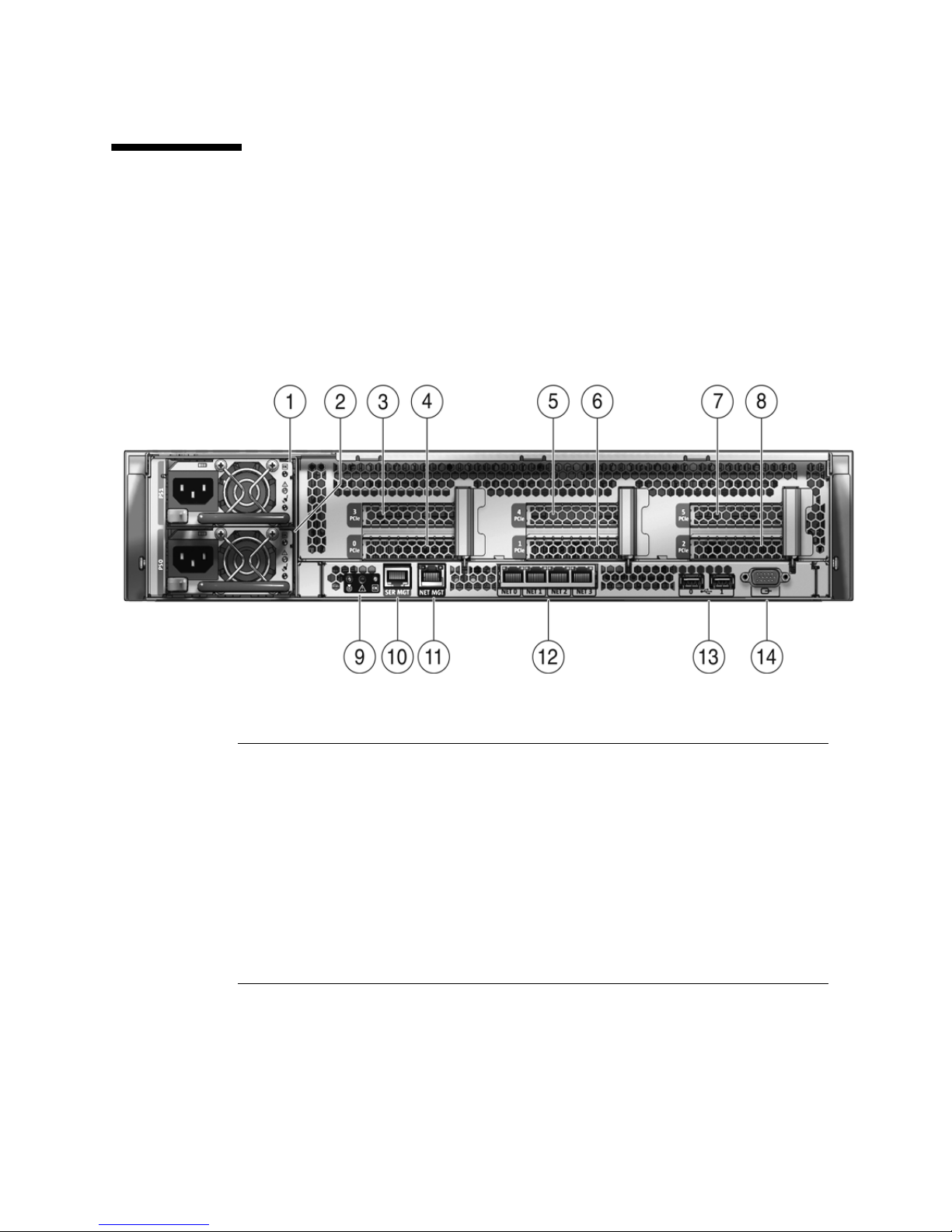
FIGURE 1-5 shows rear panel features on the Sun Fire X4440. For more detailed
information about ports and their uses, see the Sun Fire X4450 Server Installation
Guide. For a detailed description of PCIe slots, see Section 4.4, “Servicing PCIe
Risers” on page 4-21.
FIGURE 1-5 Rear Panel Features
Figure Legend
1 PSU 1 9 Rear Panel System Status LEDs
Locator LED/Locator button (white)
Service Action Required LED (amber)
Power/OK LED (green)
2 PSU 0 10 Serial Management Port (SER MGT)
3 PCIe 3 11 Network Management Port (NET MGT)
4 PCIe 0 NMI button (Behind panel, not shown)
5 PCIe 4 Reset Button (Behind panel, not shown)
5 PCIe 1 12 Gbit Ethernet Ports (0, 1, 2, 3)
7 PCIe 5 13 USB Ports (0, 1)
8 PCIe 2 14 HD15 Video Port
1-10 Sun Fire X4440 Server Service Manual • September 2010

1.5 Illustrated Parts Breakdown
The following illustrations provide exploded views of system components. Use these
illustrations, and the accompanying tables, to identify parts in your system.
FIGURE 1-6 I/O Components (Sun Fire X4440)
Figure Legend
1 To p C ove r 5 Drives (16)
2 Hard Disk Backplane 6 DVD/USB Module
3 Hard Disk Cage 7 Right Control Panel Light Pipe Assembly
4 Left Control Panel Light Pipe Assembly
Chapter 1 Sun Fire X4440 Server Overview 1-11

FIGURE 1-7 Power Distribution/Fan Module Components (Sun Fire X4440)
Figure Legend
1 Paddle Card 5 Fan Modules
2 Power Distribution Board/Bus Bar Assembly 6 Fan Boards
3 PSU Backplane 7 Air Baffle
4 Power Supplies 8 Mezzanine Tray
1-12 Sun Fire X4440 Server Service Manual • September 2010

CHAPTER
2
Preparing to Service the System
This chapter describes how to prepare the Sun Fire X4440 for servicing.
The following topics are covered:
■ Section 2.1, “Safety Information” on page 2-1
■ Section 2.2, “SSD Minimum Required Firmware” on page 2-2
■ Section 2.3, “Required Tools” on page 2-2
■ Section 2.4, “Obtaining the Chassis Serial Number” on page 2-3
■ Section 2.5, “Powering Off the Server” on page 2-4
■ Section 2.6, “Extending the Server to the Maintenance Position” on page 2-5
■ Section 2.7, “Removing a Server From the Rack” on page 2-8
■ Section 2.8, “Performing Electrostatic Discharge and Antistatic Prevention
Measures” on page 2-10
■ Section 2.9, “Removing the Top Cover” on page 2-12
2.1 Safety Information
This section describes important safety information that you need to know prior to
removing or installing parts in the Sun Fire X4440 server.
Caution – Never attempt to run the server with the covers removed. Hazardous
voltage present.
Caution – Equipment damage possible. The covers must be in place for proper air
flow.
2-1

For your protection, observe the following safety precautions when setting up your
equipment:
■ Follow all Sun cautions, warnings, and instructions marked on the equipment and
described in Important Safety Information for Sun Hardware Systems (816-7190).
■ Follow all cautions, warnings, and instructions marked on the equipment and
described in the Sun Fire X4450 Server Compliance and Safety Manual.
■ Ensure that the voltage and frequency of your power source match the voltage
and frequency inscribed on the equipment’s electrical rating label.
■ Follow the electrostatic discharge safety practices as described in this chapter.
2.2 SSD Minimum Required Firmware
BIOS/ILOM Firmware
■ BIOS: 0ABMN064
■ ILOM: 3.0.3.37
Adaptec/LSI Firmware
■ Adaptec FW: 15872
■ LSI FW: 1.27.02, MPTBIOS: 6.26.00
Backplane Firmware
■ Backplane FW: 5.02.04 (LSI SAS expander)
SSD firmware
■ Intel SSD FW: 845C8626
2.3 Required Tools
The Sun Fire X4440 server can be serviced with the following tools:
■ Antistatic wrist strap
■ Antistatic mat
■ No. 1 Phillips screwdriver
■ No. 2 Phillips screwdriver
■ Non-conducting No. 1 flat-blade screwdriver (for battery removal), or equivalent
■ Non-conducting stylus or pencil (to power on server)
2-2 Sun Fire X4440 Server Service Manual • September 2010

2.4 Obtaining the Chassis Serial Number
To obtain support for your server, you need your chassis serial number. You can find
a chassis serial number label on the server front panel on the left side.
Another chassis serial number label is on the top of the server.
FIGURE 2-1 Chassis Serial Number Label
▼ To View Chassis Serial Number
To view information about a system component, you need the Read Only (o) role
enabled.
See FIGURE 2-1.
1. Log in to the ILOM CLI.
2. At the prompt, type:
-> cd /SYS
/SYS
-> cd MB
/SYS/MB
-> show chassis_serial_number type
/SYS/MB
Properties:
chassis_serial_number = 0811QAD01C
type = Motherboard
For more information, see Sun Integrated Lights Out Manager (ILOM) 3.0 CLI
Procedures Guide (820-6412).
Chapter 2 Preparing to Service the System 2-3

2.5 Powering Off the Server
To remove main power from the server, use one of the methods shown in the
following table.
TABLE 2-1 Shutdown Procedures
Shutdown Method
Graceful shutdown Use a pen, or other non-conducting pointed object, to press and release the Power
button on the front panel. Pressing the power button causes Advanced
Configuration and Power Interface (ACPI)–enabled operating systems to perform
an orderly shutdown of the operating system. Servers not running ACPI-enabled
operating systems will shut down to standby power mode immediately.
Emergency shutdown Press and hold the Power button for at least four seconds until the main power is
off and the server enters standby power mode. See
When the main power is off, the Power/OK LED on the front panel flashes,
indicating that the server is in standby power mode.
Caution - All applications and files will be closed abruptly without
saving changes. File system corruption might occur.
ILOM SP CLI shutdown See Section 2.5.1, “Powering Off the Server Using the Service Processor
Command Line” on page 2-5.
FIGURE 2-2.
FIGURE 2-2 Front Panel Power/OK LED
Caution – To completely power off the server, you must disconnect the AC power cords
from the rear panel of the server.
2-4 Sun Fire X4440 Server Service Manual • September 2010

2.5.1 Powering Off the Server Using the Service
Processor Command Line
You can use the service processor to perform a graceful shutdown of the server and
ensure that all of your data is saved and the server is ready for restart.
Refer to the Solaris
1. Log in as a superuser or equivalent.
Depending on the type of problem, you might want to view server status or log
files, or run diagnostics before you shut down the server.
2. Notify affected users.
3. Save any open files and quit all running programs.
Refer to your application documentation for specific information.
4. Shut down all logical domains.
5. Shut down the Solaris OS.
6. Open an SSH session.
7. Log in to the Service Processor.
8. Type:
stop /SYS
or
cd /SP/CtrlInfo
™ operating system documentation for additional information.
set powerctrl=off
2.6 Extending the Server to the Maintenance
Position
The following components can be serviced with the server in the maintenance
position:
■ Hard drives
■ SSDs
■ Fan modules
■ Power supplies
Chapter 2 Preparing to Service the System 2-5

■ DVD/USB module
■ Fan power boards
■ DDR2 DIMMs
■ PCIe cards
■ Motherboard battery
If the server is installed in a rack with extendable slide rails, use this procedure to
extend the server to the maintenance position.
1. (Optional) Type the following command from the service processor (SP) prompt
-> to locate the system that requires maintenance.
-> set /SYS/LOCATE status=on
Locator indicator is on.
After you have located the server, press the Locator LED/Locator button to turn it
off.
2. Verify that no cables will be damaged or will interfere when the server is
extended.
Although the cable management arm (CMA) that is supplied with the server is
hinged to accommodate extending the server, you should ensure that all cables
and cords are capable of extending.
3. Extend the lower floor arm on the cabinet for safety, if present.
4. From the front of the server, release the two slide release latches (
Squeeze the green slide release latches to release the slide rails.
FIGURE 2-3).
2-6 Sun Fire X4440 Server Service Manual • September 2010

FIGURE 2-3 Slide Release Latches
5. While squeezing the slide release latches, slowly pull the server forward until
the slide rails latch.
Chapter 2 Preparing to Service the System 2-7

2.7 Removing a Server From the Rack
The server must be removed from the rack to service the following components:
■ Motherboard
■ Power distribution board
■ Power supply backplane
■ Vertical PDB card
■ Disk cage
■ Drives backplane
■ Front panel light-pipe assemblies
Caution – If necessary, use two people to dismount and carry the
chassis.
To remove a server from the rack:
1. Disconnect all cables and power cords from the server.
Label the cables (optional).
2. Extend the lower floor arm on the cabinet for safety, if present
3. Extend the server to the maintenance position.
See Section 2.6, “Extending the Server to the Maintenance Position” on page 2-5.
4. Press the metal lever that is located on the inner side of the rail to disconnect
the cable management arm (CMA) from the rail assembly (
FIGURE 2-4).
The CMA is still attached to the cabinet, but the server chassis is now
disconnected from the CMA.
2-8 Sun Fire X4440 Server Service Manual • September 2010

FIGURE 2-4 Metal Lever and Cable Management Arm
Caution – If necessary, use two people to dismount and carry the
chassis.
5. From the front of the server, pull the release tabs forward and pull the server
forward until it is free of the rack rails (
A release tab is located on each rail.
FIGURE 2-5).
Chapter 2 Preparing to Service the System 2-9

FIGURE 2-5 Release Tabs and Slide Assembly
6. Set the server on a sturdy work surface.
2.8 Performing Electrostatic Discharge and
Antistatic Prevention Measures
2.8.1 Electrostatic Discharge Safety Measures
Electrostatic discharge (ESD) sensitive devices, such as the motherboards, PCI cards,
drives, SSDs, and memory cards, require special handling.
Caution – Circuit boards, drives, and SSDs contain electronic components that are
extremely sensitive to static electricity. Ordinary amounts of static electricity from
clothing or the work environment can destroy the components located on these
boards. Do not touch the components without antistatic precautions, especially along
the connector edges.
2-10 Sun Fire X4440 Server Service Manual • September 2010

Caution – You must disconnect both power supplies before servicing any of the
components documented in this chapter.
2.8.1.1 Using an Antistatic Wrist Strap
Wear an antistatic wrist strap and use an antistatic mat when handling components
such as drive assemblies, circuit boards, or PCI cards. When servicing or removing
server components, attach an antistatic strap to your wrist and then to a metal area
on the chassis. Following this practice equalizes the electrical potentials between you
and the server.
Note – An antistatic wrist strap is not included in the accessory kit for the Sun Fire
X4440 Server. However, antistatic wrist straps are still included with options.
2.8.1.2 Using an Antistatic Mat
Place static-sensitive components such as motherboards, memory, and other PCBs on
an antistatic mat.
2.8.2 Antistatic Handling Procedure
1. Prepare an antistatic surface to set parts on during the removal, installation, or
replacement process.
Place static-sensitive components such as the printed circuit boards on an
antistatic mat. The following items can be used as an antistatic mat:
■ Antistatic bag used to wrap a Sun replacement part
■ Sun ESD mat, part number 250-1088
■ A disposable antistatic mat (shipped with some replacement parts or optional
system components)
2. Attach an antistatic wrist strap.
When servicing or removing server components, attach an antistatic strap to your
wrist and then to a metal area on the chassis.
Chapter 2 Preparing to Service the System 2-11

2.9 Removing the Top Cover
The top cover and fan door are integrated.
Note – Some field-replaceable units (FRUs) require removal of the rear cover.
1. Unlatch the fan module door. (
Pull the two release tabs back to release the door. Rotate the fan door to the open
position and hold it there.
2. Press the top cover release button and slide the top cover to the rear about a
half-inch (12.7 mm). [2]
3. Lift up and remove the top cover. [3]
FIGURE 2-6 [1])
Caution – If the top cover is removed before the server is powered off, the server
will immediately go into Standby mode.
FIGURE 2-6 Removing the Top Cover
2-12 Sun Fire X4440 Server Service Manual • September 2010

Chapter 2 Preparing to Service the System 2-13

2-14 Sun Fire X4440 Server Service Manual • September 2010

CHAPTER
3
Servicing Customer-Replaceable
Devices
This chapter describes how to replace the hot-swappable and hot-pluggable
customer-replaceable units (CRUs) in the Sun Fire X4440 Server. A
customer-replaceable unit can be replaced by anyone.
The following topics are covered:
■ Section 3.1, “Devices That Are Hot-Serviceable” on page 3-1
■ Section 3.2, “Servicing Drives” on page 3-2 (CRU)
■ Section 3.3, “Servicing Solid-State Drives (SSDs)” on page 3-8 (CRU)
■ Section 3.4, “Using Drive Fillers” on page 3-10 (CRU)
■ Section 3.5, “Servicing Fan Modules” on page 3-10 (CRU)
■ Section 3.6, “Servicing Power Supplies” on page 3-16 (CRU)
■ Section 3.7, “Servicing the DVD/USB Module” on page 3-22 (CRU)
3.1 Devices That Are Hot-Serviceable
3.1.1 Hot-Pluggable Devices
Hot-pluggable devices can be removed and installed while the server is running, but
you must perform administrative tasks before or after installing the hardware (for
example, mounting a drive).
3-1

In the Sun Fire X4440, only drives are hot-pluggable. To hot-plug a drive you must
take the drive offline (to prevent any applications from accessing it, and to remove
the logical software links to it) before you can safely remove it. See Section 3.2,
“Servicing Drives” on page 3-2.
3.1.2 Hot-Swappable Devices
Hot-swappable devices can be removed and installed while the server is running
without affecting the rest of the server ’s capabilities.
In the Sun Fire X4440, the following devices are hot-swappable:
■ Fan modules. See Section 3.5, “Servicing Fan Modules” on page 3-10.
■ Power supplies. See Section 3.6, “Servicing Power Supplies” on page 3-16.
Note – The chassis-mounted drives can be hot-swappable, depending on how they
are configured. See Section 3.2, “Servicing Drives” on page 3-2.
3.2 Servicing Drives
The following topics are covered:
■ Section 3.2.1, “Sun Fire X4440 Server Drive Guidelines” on page 3-2
■ Section 3.2.2, “Drive Status LED Reference” on page 3-3
■ Section 3.2.3, “Removing a Drive” on page 3-4
■ Section 3.2.4, “Installing a Drive” on page 3-6
Note – CRU: This customer-replaceable unit can be replaced by anyone.
3.2.1 Sun Fire X4440 Server Drive Guidelines
TABLE 3-1 shows physical drive locations for a Sun Fire X4440 server with 8 drives.
3-2 Sun Fire X4440 Server Service Manual • September 2010

FIGURE 3-1 Server Front
3.2.2 Drive Status LED Reference
FIGURE 3-2 Drive Status LEDs
Figure Legend
Legend LED Symbol Color Lights when
1
OK to
Remove
Blue A drive can be removed safely during a
hot-plug operation.
Note - The blue "OK to Remove" LED
requires OS support and is not functional
with all operating systems.
2
Service
Required
Amber The system is running and the drive is
faulty. The front and rear panel Service
Required LEDs are also lit if the system
detects a drive fault.
3
OK/Activity Green Data is being read from or written to the
drive.
Chapter 3 Servicing Customer-Replaceable Devices 3-3

3.2.3 Removing a Drive
Drives can be hot-plugged or cold-plugged. Drives in the Sun Fire X4440 might be
hot-pluggable, depending on the drive configuration.
To hot-plug a drive you must take the drive offline (to prevent applications from
accessing it, and to remove the logical software links to it) before you can safely
remove it.
To remove a drive from a Sun Fire X4440:
1. Identify the drive you want to remove.
The amber Service Required LED might be lit. For specific drive locations, see
Section 3.2.1, “Sun Fire X4440 Server Drive Guidelines” on page 3-2.
2. Determine if the drive can be hot-plugged, or cold-plugged.
The following conditions might prevent you from hot-plugging a drive. You must
power off the server, if the drive:
■ Contains the operating system, and the operating system is not mirrored on
another drive.
■ Cannot be logically isolated from the online operations of the server.
3. Do one of the following:
■ To hot-plug a drive:
Unconfigure the drive, as required. You must take the drive offline before you
can safely remove it. Placing the drive offline prevents applications from
accessing the drive, and removes logical software links to the drive.
See one of the following HBA documents, if your system uses RAID:
For Sun StorageTek: Sun StorageTek RAID Manager Software User's Guide
For LSI MegaRAID Storage Manager (MSM): x64 Server Utilities Reference
Manual
■ To cold-plug a drive:
You must power off the server before you can safely remove the drive. Do one
of the procedures described in Section 2.5, “Powering Off the Server” on
page 2-4.
4. On the drive you plan to remove, push the drive release button to open the latch
(
FIGURE 3-3 [1]).
5. Grasp the latch [2] and pull the drive out of the drive slot [3].
Caution – The latch is not an ejector. Do not bend it too far to the right. Doing so can
damage the latch.
3-4 Sun Fire X4440 Server Service Manual • September 2010

FIGURE 3-3 Locating the Drive Release Button and Latch
3.2.4 Installing a Drive
Installing a drive into the Sun Fire X4440 Server is a two-step process. You must first
install a drive into the drive slot, and then configure that drive to the server.
Caution – Before inserting a replacement drive, wait 15 seconds, and verify that
your monitoring or administration application has detected the missing or failed
drive.
To install a drive into a Sun Fire X4440 server:
1. If necessary, remove the drive fillers from the chassis.
The Sun Fire X4440 might have as many as eight drive fillers covering unoccupied
drive slots.
Chapter 3 Servicing Customer-Replaceable Devices 3-5

2. Determine the drive slot location for the replacement drive.
If you removed an existing drive from a slot in the server, you must install the
replacement drive in the same slot as the drive that was removed. Drives are
physically addressed according to the slot in which they are installed. See
TABLE 3-1 for drive locations.
3. Slide the drive into the drive slot until it is fully seated. (
FIGURE 3-4 Installing a Drive
FIGURE 3-4)
4. Close the latch to lock the drive in place.
5. Do one of the following:
■ If you have hot-plugged the drive:
Configure the drive. See one of the following HBA documents:
For Sun StorageTek: Sun StorageTek RAID Manager Software User's Guide
For LSI MegaRAID Storage Manager (MSM): x64 Server Utilities Reference
Manual
■ If you have cold-plugged the drive:
Restore power to the server. Do the procedure described in Section 6.4,
“Powering On the Server” on page 6-6.
3-6 Sun Fire X4440 Server Service Manual • September 2010

3.3 Servicing Solid-State Drives (SSDs)
The following topics are covered:
■ Section 3.3.1, “Solid-State Drive Guidelines” on page 3-8
■ Section 3.3.2, “Removing a Solid-State Drive” on page 3-9
■ Section 3.3.3, “Installing a Solid-State Drive” on page 3-9
See also Section 3.4, “Using Drive Fillers” on page 3-10
For latest software versions that support SSDs, see Section 2.2, “SSD Minimum
Required Firmware” on page 2-2.
Note – CRU: This customer-replaceable unit can be replaced by anyone.
3.3.1 Solid-State Drive Guidelines
The Sun Fire X4440 servers support solid-state drives (SSDs) under the following
conditions:
Sun Fire X4440 with on-board controller:
■ One to 4 SSDs can be installed.
■ Hard drives are not supported.
■ SSDs can be installed in any drive slot.
Chapter 3 Servicing Customer-Replaceable Devices 3-7

Sun Fire X4440 with HBA:
■ One to 4 SSDs can be installed. The remaining slots can be filled with hard drives
that can equal up to 8 drives total. Example: 2 SSD and 6 hard drives.
■ SSDs can be installed in any drive slot.
■ When replacing or installing a SSD to be included in a RAID configuration, in the
Sun Fire X4440 system, make sure that the firmware on the newly installed SSD is
the same as the firmware that is installed on the other SSDs in the RAID volume
Note – You can create RAID volumes with SAS hard drives and SATA SSDs, as long
as you do not mix them in a same volume.
The following cable kits are used for the HBA controller when using hard drives and
SSDs:
TABLE 3-1 Cable Kits for HBA Controller
System Cable Kit Order Number
Sun Fire X4240 and X4440 SAS/SATA HBA (2 cables) 4282A
The following cable kits are used for the on-board controller with SSDs:
TABLE 3-2 Cable Kits for HBA Controller
System Cable Kit Order Number
Sun Fire X4240 and X4440 SATA On-Board Only (2 cables) 4283A
3.3.2 Removing a Solid-State Drive
The procedure to remove an SSD is the same as removing the hard drive. See
Section 3.2.3, “Removing a Drive” on page 3-4.
3.3.3 Installing a Solid-State Drive
The procedure to install an SSD is the same as installing the hard drive. See
Section 3.2.4, “Installing a Drive” on page 3-6.
3-8 Sun Fire X4440 Server Service Manual • September 2010

.
3.4 Using Drive Fillers
All drive slots in the Sun Fire X4440 Server must have drive fillers in place during
operation to maintain efficent airflow. To remove fillers, pull the ejector and pull the
filler out of the chassis. (
FIGURE 3-5 Drive Filler
FIGURE 3-5)
3.5 Servicing Fan Modules
The following topics are covered:
■ Section 3.5.1, “About Sun Fire X4440 Fans” on page 3-11
■ Section 3.5.2, “Fan Module LED Reference” on page 3-11
■ Section 3.5.3, “Detecting Fan Module Failure” on page 3-12
■ Section 3.5.4, “Removing a Fan Module” on page 3-13
■ Section 3.5.5, “Installing a Fan Module” on page 3-14
Note – CRU: This customer-replaceable unit can be replaced by anyone.
Chapter 3 Servicing Customer-Replaceable Devices 3-9

3.5.1 About Sun Fire X4440 Fans
Six pairs of fan modules are located under the top cover door, providing N+1 cooling
redundancy. Each fan module contains two fans mounted in an integrated,
hot-swappable CRU.
If a fan module fails, replace the fan as soon as possible to maintain server
availability.
Fan modules are hot-swappable and can be removed and installed while the server is
running without affecting the rest of the server ’s capabilities.
3.5.2 Fan Module LED Reference
Each fan module contains LEDs that are visible when you open the fan tray access
door.
TABLE 3-4 describes fan tray module LEDs and their functions.
TABLE 3-3 Fan Module Status LEDs
LED Color Lights when...
Power/OK Green The system is powered on and the fan
module is functioning correctly.
Service Required Amber The fan module is faulty. The front and rear
panel Service Required LEDs are also lit if
the system detects a fan module fault.
FIGURE 3-6 shows the fan module locations.
3-10 Sun Fire X4440 Server Service Manual • September 2010

FIGURE 3-6 Fan Module Locations
3.5.3 Detecting Fan Module Failure
The following LEDs are lit when a fan module fault is detected:
■ Service Required LEDs, on the front and rear of the server
■ Top Fan LED, on the front of the server
■ Fan Fault LED, on or adjacent to the faulty fan module
If an overtemperature condition occurs, the front panel CPU overtemperature LED
becomes lit and a message is displayed on the console and logged by the ILOM.
Refer to the Sun Integrated Lights Out Manager User's Guide.
The system Overtemp LED might be lit if a fan fault causes an increase in system
operating temperature. See Chapter 1, Section 1.3, “Sun Fire X4440 Front Panel
Features” on page 1-9 for more information about system status LEDs.
Chapter 3 Servicing Customer-Replaceable Devices 3-11

FIGURE 3-7 Detecting a Faulty Fan Module
3.5.4 Removing a Fan Module
Caution – Hazardous moving parts. Unless the power to the server is completely
shut down, the only service permitted in the fan compartment is the replacement of
the fan modules by trained personnel.
1. Extend the server into the maintenance position.
See Section 2.6, “Extending the Server to the Maintenance Position” on page 2-5.
2. Unlatch the fan module door.
Pull the release tabs back to release the door. Open the top cover toward the rear
of the server.
Note – Close the top cover door immediately after replacing the fan to maintain
airflow in the server. Leaving the door open for more than 60 seconds while the
server is running might cause the server to overheat and shut down.
3. Identify the faulty fan module with a corresponding Service Required LED.
The Fan Fault LEDs are located on the fan board.
4. Using thumb and forefinger in between the two fans, pull the fan module up
and out of the connector.
3-12 Sun Fire X4440 Server Service Manual • September 2010

Caution – When changing the fan modules, note that only the fan modules can be
removed or replaced. Do not service any other components in the fan compartment
unless the system is shut down and the power cords are removed.
FIGURE 3-8 Removing a Fan Module
3.5.5 Installing a Fan Module
1. With the top cover door open, install the replacement fan module into the server
(
FIGURE 3-9).
The fan modules are keyed to ensure that they are installed in the correct
orientation.
Chapter 3 Servicing Customer-Replaceable Devices 3-13

FIGURE 3-9 Installing a Fan Module
2. Apply firm pressure to fully seat the fan module.
3. Verify that the Fan OK LED is lit, and that the Fan Fault LED on the replaced
fan module is not lit.
4. Close the top cover door.
5. Verify that the Top Fan LED, Service Required LEDs, and the Locator
LED/Locator button are not lit.
See Section 1.2, “Sun Fire X4440 Server Chassis Overview” on page 1-3 for more
information about identifying and interpreting system LEDs.
3-14 Sun Fire X4440 Server Service Manual • September 2010

3.6 Servicing Power Supplies
Some versions of the Sun Fire X4440 Servers are equipped with redundant
hot-swappable power supplies. Redundant power supplies enable you to remove
and replace a power supply without shutting the server down, provided that the
other power supply is online and working.
FIGURE 3-10 Power Supplies
Caution – If a power supply fails and you do not have a replacement available,
leave the failed power supply installed to ensure proper air flow in the server.
The following topics are covered:
■ Section 3.6.1, “Detecting Power Supply Failure” on page 3-17
■ Section 3.6.2, “Power Supply LED Reference” on page 3-17
■ Includes specific information about power supply status LEDs.
■ Section 3.6.3, “Removing a Power Supply” on page 3-18
■ Section 3.6.4, “Installing a Power Supply” on page 3-20
Note – CRU: This customer-replaceable unit can be replaced by anyone.
Chapter 3 Servicing Customer-Replaceable Devices 3-15

3.6.1 Detecting Power Supply Failure
The following LEDs are lit when a power supply fault is detected:
■ Front and rear Service Required LEDs
■ Rear PS Failure LED on the bezel of the server
■ Failure LED on the faulty power supply
See Section 3.6.2, “Power Supply LED Reference” on page 3-17 for power supply LED
information.
See Section 1.3, “Sun Fire X4440 Front Panel Features” on page 1-9 and Section 1.4,
“Sun Fire X4440 Rear Panel Features” on page 1-10 for more information about
identifying and interpreting system LEDs.
3.6.2 Power Supply LED Reference
Each power supply contains a series of LEDs on the rear panel of the system.
FIGURE 3-11 Power Supply Status LEDs
3-16 Sun Fire X4440 Server Service Manual • September 2010

Figure Legend
Legend LED Symbol Color Lights when
1
2
3
AC Present Green The power supply is plugged in and
Service Required Amber The power supply is faulty.
OK to Remove Green A power supply can be removed
3.6.3 Removing a Power Supply
If space is limited behind the server, you might need to remove the server from the
rack. See Section 2.7, “Removing a Server From the Rack” on page 2-8.
Caution – Hazardous voltages are present. To reduce the risk of electric shock and
danger to personal health, follow the instructions.
AC power is available, regardless of
system power state.
The front and rear panel Service
Required LEDs are also lit if the
system detects a power supply fault.
safely during a hot–swap operation.
1. Determine which power supply (0 or 1) requires replacement.
A lit (amber) failure LED on a power supply indicates that a failure was detected.
2. Gain access to the rear of the server where the faulty power supply is located.
3. Release the cable management arm (CMA). (
FIGURE 3-12)
The CMA is located at the rear of the server rack.
a. Press and hold the tab.
b. Rotate the cable management arm out of the way so that you can access the
power supply.
Chapter 3 Servicing Customer-Replaceable Devices 3-17

FIGURE 3-12 Releasing the Cable Management Arm
4. Disconnect the power cord from the faulty power supply.
5. Grasp the power supply handle and press the release latch. (
6. Pull the power supply out of the chassis.
FIGURE 3-13)
3-18 Sun Fire X4440 Server Service Manual • September 2010

FIGURE 3-13 Power Supply Release Handle
3.6.4 Installing a Power Supply
1. Align the replacement power supply with the empty power supply chassis bay.
2. Slide the power supply into the bay until it is fully seated. (
3. Reconnect the power cord (or cords) to the power supply (or supplies).
Verify that the AC Present LED is lit.
4. Close the CMA, inserting the end of the CMA into the rear left rail bracket
(
FIGURE 3-12).
FIGURE 3-14)
Chapter 3 Servicing Customer-Replaceable Devices 3-19

FIGURE 3-14 Installing a Power Supply
5. Verify that the following LEDs are not lit:
■ Failure LED on the replaced power supply
■ Service Required LED
■ Front Service Required LED
■ Rear Service Required LED
Note – See Section 1.3, “Sun Fire X4440 Front Panel Features” on page 1-9 and
Section 1.4, “Sun Fire X4440 Rear Panel Features” on page 1-10 for more information
about identifying and interpreting system LEDs.
3-20 Sun Fire X4440 Server Service Manual • September 2010

6. Verify the status of the power supplies.
Solaris OS: At the -> prompt, type the showenvironment command.
Linux OS: Refer to the Sun Integrated Lights Out Manager User's Guide.
Windows OS: Refer to the Sun Integrated Lights Out Manager User's Guide.
3.7 Servicing the DVD/USB Module
The DVD drive and front USB board are mounted in a removable module that is
accessible from the front panel of the system. The DVD/USB module must be
removed from the drive cage to service the drives backplane.
Note – CRU: This customer-replaceable unit can be replaced by anyone.
3.7.1 Removing the DVD/USB Module
1. Remove media from the drive.
2. Prepare the server for service.
a. Power off the server.
See Section 2.5, “Powering Off the Server” on page 2-4.
b. Disconnect the power cord (or cords) from the power supply (or supplies).
See Section 2.5, “Powering Off the Server” on page 2-4.
c. Attach an antistatic wrist strap.
See Section 2.8, “Performing Electrostatic Discharge and Antistatic Prevention
Measures” on page 2-10.
3. Remove the Sun Fire X4440 HDD7 hard drive.
See Section 1.2, “Sun Fire X4440 Server Chassis Overview” on page 1-3 for drive
locations.
4. Release the DVD/USB module from the drives backplane. (
Use the sliding pull tab in the drive bay below the DVD/USB module to detach
the module from the backplane.
5. Slide the DVD/USB module out of the drive cage.
FIGURE 3-15)
Chapter 3 Servicing Customer-Replaceable Devices 3-21

6. Place the module on an antistatic mat.
FIGURE 3-15 Removing the DVD/USB Module
3.7.2 Installing the DVD/USB Module
1. Slide the DVD/USB module into the front of the chassis until it seats.
(
FIGURE 3-16)
2. Install the drive you removed during the DVD/USB module removal procedure.
3. Power on the server.
See Section 6.4, “Powering On the Server” on page 6-6.
3-22 Sun Fire X4440 Server Service Manual • September 2010

FIGURE 3-16 Installing the DVD/USB Module
Chapter 3 Servicing Customer-Replaceable Devices 3-23

3-24 Sun Fire X4440 Server Service Manual • September 2010

CHAPTER
4
Servicing Motherboard Components
This chapter describes how to replace the motherboard and its components in the
Sun Fire X4440 server.
Note – Before performing any of the procedures in this chapter, perform the
procedures described in Chapter 2, Preparing to Service the System.
Some of the procedures in this chapter are for customer-replaceable units (CRUs) and
some are for field-replaceable units (FRUs), as noted in the procedures and in the list
below. FRU components should be replaced only by trained service technicians.
Contact your Sun Service representative for assistance with FRU replacements.
The following topics are covered in this chapter:
■ Section 4.1, “Servicing DDR2 DIMMs” on page 4-2 (CRU)
■ Section 4.2, “Servicing the Mezzanine Tray” on page 4-12 (CRU)
■ Section 4.3, “Servicing Air Ducts” on page 4-16 (CRU)
■ Section 4.4, “Servicing PCIe Risers” on page 4-21 (CRU)
■ Section 4.5, “Servicing PCIe Cards” on page 4-24 (CRU)
■ Section 4.6, “Servicing the Battery” on page 4-31 (CRU)
■ Section 4.7, “Servicing the Motherboard Assembly” on page 4-34 (FRU)
■ Section 4.8, “Servicing CPUs” on page 4-42 (FRU)
■ Section 4.9, “Resetting Passwords and Clearing CMOS NVRAM” on page 4-49
■ Section 4.10, “Recovering From Corrupt Service Processor Software” on page 4-52
■ Section 4.11, “Using the Reset and NMI Switches” on page 4-55
■ Section 4.12, “Upgrading Two Socket to Four Socket” on page 4-55
Caution – Never attempt to run the server with the covers removed. Hazardous
voltage present.
4-1

Caution – Equipment damage possible. The covers must be in place for proper air
flow.
4.1 Servicing DDR2 DIMMs
This section describes how to diagnose and replace faulty DDR2 (Double-Data Rate)
DIMMs. The following topics are covered:
■ “Identifying Faulty DIMMs” on page 4-2
■ “DDR2 DIMM Guidelines” on page 4-5
■ (Includes additional DDR2 DIMM information.)
■ “Removing DDR2 DIMMs” on page 4-7
■ “Installing DDR2 DIMMs” on page 4-9
■ “Installing Additional DDR2 DIMMs” on page 4-11
(How to upgrade the server with additional DDR2 DIMMs)
Refer to the Sun Fire X4140, X4240, and X4440 Servers Diagnostics Guide for additional
DIMM troubleshooting information.
Note – CRU: This customer-replaceable unit can be replaced by anyone.
Caution – This procedure requires that you handle components that are sensitive to
static discharge. This sensitivity can cause the component to fail. To avoid damage,
ensure that you follow antistatic practices as described in Section 2.8.1, “Electrostatic
Discharge Safety Measures” on page 2-10.
4.1.1 Identifying Faulty DIMMs
The system fault LED lights if the system detects a DDR2 DIMM fault.
1. Prepare the server for service.
a. Power off the server.
See Section 2.5, “Powering Off the Server” on page 2-4.
4-2 Sun Fire X4440 Server Service Manual • September 2010

b. Disconnect the power cord (or cords) from the power supply (or supplies).
See Section 2.5, “Powering Off the Server” on page 2-4.
c. Slide the server out of the rack.
See Section 2.7, “Removing a Server From the Rack” on page 2-8.
d. Attach an antistatic wrist strap.
See Section 2.8, “Performing Electrostatic Discharge and Antistatic Prevention
Measures” on page 2-10.
e. Remove the top cover.
See Section 2.9, “Removing the Top Cover” on page 2-12.
2. Press and hold the Fault Remind button on the mezzanine tray to identify
which DDR2 DIMM is faulty. (
FIGURE 4-1)
3. Note the location of faulty DDR2 DIMMs.
A faulty DDR2 DIMM is identified with a corresponding flashing amber LED on
the motherboard.
4. Ensure that all DDR2 DIMMs are seated correctly in their slots. If re-seating the
memory does not fix the problem, remove and replace the faulty memory.
Note – Refer to the Sun Fire X4140, X4240, and X4440 Servers Diagnostics Guide for
more information about DIMM System Event Log (SEL) messages.
Chapter 4 Servicing Motherboard Components 4-3

FIGURE 4-1 Fault Remind Button Locations
4-4 Sun Fire X4440 Server Service Manual • September 2010

4.1.2 DDR2 DIMM Guidelines
Use the DDR2 DIMM guidelines, and FIGURE 4-2 to help you plan the memory
configuration of your server.
■ There are 32 slots, 16 on the mezzanine tray, and 16 on the motherboard, in four
branches, that hold industry-standard DDR2 DIMM modules.
■ All DDR2 DIMMs must be the same density (same type).
■ The Sun Fire X4440 supports the following configurations:
■ From: 2 DDR2 DIMMs (minimum configuration)
■ To: 32 DDR2 DIMMs (fully populated configuration)
In increments of 2 DDR2 DIMMs.
■ At minimum, Branch 0 must be fully populated with two DDR2 DIMMs of the
same density (same type).
Chapter 4 Servicing Motherboard Components 4-5

FIGURE 4-2 DDR2 DIMM Layout
4.1.2.1 DDR2 DIMM Placement
Refer to the service label on the cover for DDR2 DIMM placement information. Refer
to the Sun Fire X4140, X4240, and X4440 Servers Diagnostics Guide for additional DDR2
DIMM information.
The DIMM population rules for the server are as follows:
■ Each CPU can support a maximum of eight DIMMs.
■ The DIMM slots are paired and the DIMMs must be installed in pairs (0-1, 2-3, 4-5, and
6-7). The memory sockets are colored black
paired by matching colors.
4-6 Sun Fire X4440 Server Service Manual • September 2010
or white to indicate which slots are

■ DIMMs are populated starting from the outside (away from the CPU) and working
toward the inside.
■ CPUs with only a single pair of DIMMs must have those DIMMs installed in that
CPU’s outside white DIMM slots (6 and 7).
■ Only DDR2 800 Mhz, 667Mhz, and 533Mhz DIMMs are supported.
■ Each pair of DIMMs must be identical (same manufacturer, size, and speed).
Note – DDR2 DIMM names in Integrated LOM messages are displayed with the full
name, such as /SYS/MB/P0/D7.
4.1.2.2 DDR2 DIMM Fillers
DDR2 DIMM fillers are installed in all unoccupied DIMM sockets. All sockets must
be occupied by either a filler or a DDR2 DIMM. When DDR2 DIMMs are added,
remove the fillers. When DDR2 DIMM are removed, add extra fillers. Always place
fillers in empty sockets.
FIGURE 4-3 Fillers for DDR2 DIMM Slots
4.1.3 Removing DDR2 DIMMs
Caution – Ensure that all power is removed from the server before removing or
installing DDR2 DIMMs. You must disconnect the power cables before performing
this procedure.
1. Review Section 4.1.2, “DDR2 DIMM Guidelines” on page 4-5 for memory
configuration information.
2. Prepare the server for service.
Chapter 4 Servicing Motherboard Components 4-7

a. Power off the server.
See Section 2.5, “Powering Off the Server” on page 2-4.
b. Disconnect the power cord (or cords) from the power supply (or supplies).
See Section 2.5, “Powering Off the Server” on page 2-4.
c. Slide the server out of the rack.
See Section 2.7, “Removing a Server From the Rack” on page 2-8.
d. Attach an antistatic wrist strap.
See Section 2.8, “Performing Electrostatic Discharge and Antistatic Prevention
Measures” on page 2-10.
e. Remove the top cover.
See Section 2.9, “Removing the Top Cover” on page 2-12.
3. If you are replacing a faulty DDR2 DIMM, press the Fault Remind button on
the motherboard and mezzanine tray to locate the DDR2 DIMM that you want
to replace.
The faulty DDR2 DIMM LED flashes when the Fault Remind button is pressed
and held. All faulty DIMMs are indicated with an amber LED, so that you can
install the replacement DDR2 DIMM in the same location.
4. Do one of the following.
■ If the faulty DIMM is located on the mezzanine board, then lift up the air duct.
(
FIGURE 4-4 [1]).
■ If the faulty DIMM is located on the motherboard, then remove the mezzanine
tray. See Section 4.2, “Servicing the Mezzanine Tray” on page 4-12.
Tip – Make a note of the faulty DDR2 DIMM location.
5. Push down on the ejector tabs on each side of the DDR2 DIMM until the
DIMM is released (
FIGURE 4-4).
6. Grasp the top corners of the faulty DDR2 DIMM and remove it from the server.
4-8 Sun Fire X4440 Server Service Manual • September 2010

FIGURE 4-4 Removing DDR2 DIMM
7. Place the DDR2 DIMM on an antistatic mat.
8. Repeat Step 5 through Step 7 to remove any additional DDR2 DIMMs.
4.1.4 Installing DDR2 DIMMs
Caution – Ensure that all power is removed from the server before removing or
installing DDR2 DIMMs, or damage to the DDR2 DIMM might occur. You must
disconnect all power cables from the system before performing this procedure.
Tip – See Section 4.1.2, “DDR2 DIMM Guidelines” on page 4-5 for information about
configuring the DDR2 DIMMs.
1. Unpack the replacement DDR2 DIMMs and place them on an antistatic mat.
2. Ensure that the ejector tabs are in the open position.
3. Line up the replacement DDR2 DIMM with the connector (
Align the DDR2 DIMM notch with the key in the connector. This ensures that the
DDR2 DIMM is oriented correctly.
FIGURE 4-5).
Chapter 4 Servicing Motherboard Components 4-9

4. Push the DDR2 DIMM into the connector until the ejector tabs lock the DDR2
DIMM in place.
If the DDR2 DIMM does not easily seat into the connector, verify that the
orientation of the DDR2 DIMM is as shown in
FIGURE 4-5. If the orientation is
reversed, damage to the DDR2 DIMM might occur.
5. Repeat Step 2 through Step 4 until all replacement DDR2 DIMM are installed.
6. Do one of the following.
■ If the faulty DIMM was located on the mezzanine board, then lower the air
duct. (
■ If the faulty DIMM was located on the motherboard, then replace the
FIGURE 4-5 [1]).
mezzanine tray. See Section 4.2, “Servicing the Mezzanine Tray” on page 4-12.
7. Return the server to operation.
a. Install the top cover.
See Section 6.1, “Installing the Top Cover” on page 6-2.
b. Slide the server into the rack.
See Section 6.3, “Returning the Server to the Normal Rack Position” on
page 6-4.
c. Reconnect the power cord (or cords) to the power supply (or supplies).
Verify that the AC Present LED is lit.
See Section 6.4, “Powering On the Server” on page 6-6.
d. Power on the server.
See Section 6.4, “Powering On the Server” on page 6-6.
4-10 Sun Fire X4440 Server Service Manual • September 2010

FIGURE 4-5 Installing DDR2 DIMMs
4.1.5 Installing Additional DDR2 DIMMs
Before you begin, see Section 4.1.2, “DDR2 DIMM Guidelines” on page 4-5, for
information about DDR2 DIMM configuration guidelines.
Caution – Ensure that all power is removed from the server before installing DDR2
DIMMs or damage to the DDR2 DIMMs might occur. You must disconnect all power
cables from the system before performing this procedure.
1. Remove the mezzanine tray, to access the DIMMs, if the DIMMs are located on
the motherboard.
See Section 4.2.1, “Removing the Mezzanine Tray” on page 4-13.
2. Remove any fillers to be replaced with DIMMs.
Set the fillers aside for future use if needed later.
3. Unpack the replacement DDR2 DIMMs and place them on an antistatic mat.
4. Ensure that the ejector tabs are in the open position.
Chapter 4 Servicing Motherboard Components 4-11

5. Line up the DDR2 DIMM with the connector (FIGURE 4-5).
Align the DDR2 DIMM notch with the key in the connector. This ensures that the
DDR2 DIMM is oriented correctly.
6. Push the DDR2 DIMM into the connector until the ejector tabs lock the DIMM
in place.
If the DDR2 DIMM does not easily seat into the connector, verify that the
orientation of the DDR2 DIMM is as shown in
FIGURE 4-4. If the orientation is
reversed, damage to the DDR2 DIMM might occur.
7. Repeat Step 2 through Step 6 until all DDR2 DIMMs are installed.
8. Do one of the following.
■ If the faulty DIMM was located on the mezzanine board, then lower the air
duct. (
■ If the faulty DIMM was located on the motherboard, then replace the
FIGURE 4-5 [1]).
mezzanine tray. See Section 4.2, “Servicing the Mezzanine Tray” on page 4-12.
9. Return the server to operation.
a. Install the top cover.
See Section 6.1, “Installing the Top Cover” on page 6-2.
b. Slide the server into the rack.
See Section 6.3, “Returning the Server to the Normal Rack Position” on
page 6-4.
c. Reconnect the power cord (or cords) to the power supply (or supplies).
Verify that the AC Present LED is lit.
See Section 6.4, “Powering On the Server” on page 6-6.
d. Power on the server.
See Section 6.4, “Powering On the Server” on page 6-6.
4.2 Servicing the Mezzanine Tray
The following topics are covered:
■ “Removing the Mezzanine Tray” on page 4-13
■ “Installing the Mezzanine Tray” on page 4-14
You must remove the mezzanine tray when removing and installing the
motherboard.
4-12 Sun Fire X4440 Server Service Manual • September 2010

Note – CRU: This customer-replaceable unit can be replaced by anyone.
Caution – Ensure that all power is removed from the server before installing
mezzanine tray or damage to system components might occur. You must disconnect
all power cables from the system before performing this procedure.
4.2.1 Removing the Mezzanine Tray
1. Prepare the server for service.
a. Power off the server.
See Section 2.5, “Powering Off the Server” on page 2-4.
b. Disconnect the power cord (or cords) from the power supply (or supplies).
See Section 2.5, “Powering Off the Server” on page 2-4.
c. Slide the server out of the rack.
See Section 2.7, “Removing a Server From the Rack” on page 2-8.
d. Attach an antistatic wrist strap.
See Section 2.8, “Performing Electrostatic Discharge and Antistatic Prevention
Measures” on page 2-10.
e. Remove the top cover.
See Section 2.9, “Removing the Top Cover” on page 2-12.
2. Unlock the two mezzanine tray tabs by pressing away from the mezzanine tray,
as shown in
3. Grab the handles and rotate the handles towards the center of the mezzanine
tray [2].
4. Lift the mezzanine tray up [3].
5. Set the mezzanine tray aside.
Place the mezzanine tray on an antistatic mat.
FIGURE 4-6. [1]
Chapter 4 Servicing Motherboard Components 4-13

FIGURE 4-6 Removing the Mezzanine Tray
4.2.2 Installing the Mezzanine Tray
1. Hold the two handles and carefully place the mezzanine tray into the
motherboard as shown in
Ensure that the mezzanine tray is aligned and fully seated. The handles should
click into the tabs.
4-14 Sun Fire X4440 Server Service Manual • September 2010
FIGURE 4-7.

FIGURE 4-7 Installing the Mezzanine Tray
2. Return the server to operation.
a. Install the top cover.
See Section 6.1, “Installing the Top Cover” on page 6-2.
b. Slide the server into the rack.
See Section 6.3, “Returning the Server to the Normal Rack Position” on
page 6-4.
c. Reconnect the power cord (or cords) to the power supply (or supplies).
Verify that the AC Present LED is lit.
See Section 6.4, “Powering On the Server” on page 6-6.
Chapter 4 Servicing Motherboard Components 4-15

d. Power on the server.
See Section 6.4, “Powering On the Server” on page 6-6.
4.3 Servicing Air Ducts
The following topics are covered:
■ Section 4.3.1, “Removing the Air Duct” on page 4-16
■ Section 4.3.2, “Installing the Air Duct” on page 4-18
The motherboard and mezzanine each have an associated air duct or baffle. You must
remove the air duct when removing and installing the following components:
■ Power distribution board
■ Power supply unit (PSU) PDB
■ Paddle card
■ Motherboard
Note – CRU: This customer-replaceable unit can be replaced by anyone.
Caution – To prevent the system from overheating, ensure that the air duct is
correctly installed before powering on the server.
4.3.1 Removing the Air Duct
1. Prepare the server for service.
a. Power off the server.
See Section 2.5, “Powering Off the Server” on page 2-4.
b. Disconnect the power cord (or cords) from the power supply (or supplies).
See Section 2.5, “Powering Off the Server” on page 2-4.
c. Slide the server out of the rack.
See Section 2.7, “Removing a Server From the Rack” on page 2-8.
4-16 Sun Fire X4440 Server Service Manual • September 2010

d. Attach an antistatic wrist strap.
See Section 2.8, “Performing Electrostatic Discharge and Antistatic Prevention
Measures” on page 2-10.
e. Remove the top cover.
See Section 2.9, “Removing the Top Cover” on page 2-12.
2. Remove the mezzanine tray, to access the air duct.
See Section 4.2.1, “Removing the Mezzanine Tray” on page 4-13.
3. Lift the air baffle out of the mezzanine tray. (
FIGURE 4-8)
4. Slide the motherboard air duct to the right to disengage the pin on the left side.
[1]
5. Slide the air duct to the left to disengage the pin on the right side. [2]
6. Move the air duct towards the back to clear the lip on the midwall.
7. Lift the air duct out of the server. [3]
8. Set the air duct aside.
Chapter 4 Servicing Motherboard Components 4-17

FIGURE 4-8 Removing the Air Duct
4.3.2 Installing the Air Duct
Caution – When the server is in operation, ensure that the air duct is correctly
installed to prevent the system from overheating.
1. Install the air duct into the chassis as shown in
Ensure that the air duct is aligned and fully seated in the chassis.
2. Install the mezzanine air baffle as shown in
Ensure that the air baffle is aligned and fully seated in the mezzanine tray.
4-18 Sun Fire X4440 Server Service Manual • September 2010
FIGURE 4-9.
FIGURE 4-9.

3. Reinstall the mezzanine tray.
See Section 4.2.2, “Installing the Mezzanine Tray” on page 4-14.
4. Return the server to operation.
a. Install the top cover.
See Section 6.1, “Installing the Top Cover” on page 6-2.
b. Slide the server into the rack.
See Section 6.3, “Returning the Server to the Normal Rack Position” on
page 6-4.
c. Reconnect the power cord (or cords) to the power supply (or supplies).
Verify that the AC Present LED is lit.
See Section 6.4, “Powering On the Server” on page 6-6.
d. Power on the server.
See Section 6.4, “Powering On the Server” on page 6-6.
Chapter 4 Servicing Motherboard Components 4-19

FIGURE 4-9 Installing the Air Duct
4-20 Sun Fire X4440 Server Service Manual • September 2010

4.4 Servicing PCIe Risers
The following topics are covered:
■ Section 4.4.1, “Removing a PCIe Riser” on page 4-21
■ Section 4.4.2, “Installing a PCIe Riser” on page 4-23
PCIe cards are installed on vertical riser assemblies. You must remove the relevant
riser assembly to access a PCIe card. You must remove all three PCIe riser assemblies
when replacing the motherboard.
Note – CRU: This customer-replaceable unit can be replaced by anyone.
Caution – This procedure requires that you handle components that are sensitive to
static discharge. This sensitivity can cause the component to fail. To avoid damage,
ensure that you follow antistatic practices as described in Section 2.8.1, “Electrostatic
Discharge Safety Measures” on page 2-10.
4.4.1 Removing a PCIe Riser
Caution – Ensure that all power is removed from the server before removing or
installing risers. You must disconnect the power cables before performing this
procedure.
1. Prepare the server for service.
a. Power off the server.
See Section 2.5, “Powering Off the Server” on page 2-4.
b. Disconnect the power cord (or cords) from the power supply (or supplies).
See Section 2.5, “Powering Off the Server” on page 2-4.
c. Attach an antistatic wrist strap.
See Section 2.8, “Performing Electrostatic Discharge and Antistatic Prevention
Measures” on page 2-10.
Chapter 4 Servicing Motherboard Components 4-21

d. Disconnect any data cables connected to the cards on the PCIe riser being
removed.
Label the cables to ensure proper connection later.
e. Slide the server out of the rack.
See Section 2.6, “Extending the Server to the Maintenance Position” on
page 2-5.
f. Remove the top cover.
See Section 2.9, “Removing the Top Cover” on page 2-12.
2. Remove the mezzanine tray, to access the riser.
See Section 4.2.1, “Removing the Mezzanine Tray” on page 4-13.
3. If you are servicing a PCIe card, locate the PCIe card position in the server.
4. Disconnect any data cables connected to the cards on the PCIe riser being
removed.
Label the cables to ensure proper connection later.
5. Remove the rear panel PCI crossbeam. (
FIGURE 4-10 [1])
a. Loosen the two captive Phillips screws on the end of the PCI crossbeam.
b. Lift the PCI crossbeam up and back to remove it from the chassis.
6. Loosen the captive retaining screw holding the front end of the riser to the
motherboard. [2]
7. Loosen the Phillips screw on the end of the riser.
8. Lift the riser up to remove it from the server.
Remove the riser and any PCIe cards attached to it as a unit.
4-22 Sun Fire X4440 Server Service Manual • September 2010

FIGURE 4-10 Removing a PCIe Riser
4.4.2 Installing a PCIe Riser
Caution – Ensure that all power is removed from the server before removing or
installing risers. You must disconnect the power cables before performing this
procedure.
1. Lower the PCIe riser and any cards attached to the PCIe riser into the system.
2. Slide the back of the riser into the motherboard rear panel stiffener.
3. Tighten the screw that secures the riser to the motherboard. (
FIGURE 4-11 [1])
4. Install the rear panel PCI crossbeam. [2]
a. Slide the crossbeam down over the PCIe risers.
b. Secure the PCI crossbeam is secured with two captive Phillips screws.
5. Return the server to operation.
a. Install the top cover.
See Section 6.1, “Installing the Top Cover” on page 6-2.
b. Connect any data cables to the PCIe card.
Route data cables through the cable management arm.
Chapter 4 Servicing Motherboard Components 4-23

c. Slide the server into the rack.
See Section 6.3, “Returning the Server to the Normal Rack Position” on
page 6-4.
d. Reconnect the power cord (or cords) to the power supply (or supplies).
Verify that the AC Present LED is lit.
See Section 6.4, “Powering On the Server” on page 6-6.
e. Power on the server.
See Section 6.4, “Powering On the Server” on page 6-6.
FIGURE 4-11 Installing a PCIe Riser
4.5 Servicing PCIe Cards
See Section 4.5.1, “Sun Fire X4440 PCIe Card Guidelines” on page 4-25 for PCIe card
configuration guidelines.
The following topics are covered:
■ Section 4.5.1, “Sun Fire X4440 PCIe Card Guidelines” on page 4-25
■ Section 4.5.2, “Removing PCIe Cards” on page 4-26
■ Section 4.5.3, “Installing PCIe Cards” on page 4-28
4-24 Sun Fire X4440 Server Service Manual • September 2010

Note – CRU: This customer-replaceable unit can be replaced by anyone.
Caution – This procedure requires that you handle components that are sensitive to
static discharge. This sensitivity can cause the component to fail. To avoid damage,
ensure that you follow antistatic practices as described in Section 2.8, “Performing
Electrostatic Discharge and Antistatic Prevention Measures” on page 2-10.
Caution – Ensure that all power is removed from the server before removing or
installing expansion cards. You must disconnect the power cables before performing
this procedure.
4.5.1 Sun Fire X4440 PCIe Card Guidelines
The PCI expansion system is configured using two types of riser cards.
Riser type 1 is used in the Riser 0 and Riser 1 positions and Riser type 2 is used in the
slot 2 position as shown in
PCIe lanes and the mechanical width desicribes the riser PCIe connector size. PCIe
cards with x4, x8 or x16 mechanical finger pins will fit in any riser slot but will
operate at the electrical lane width of the slot.
TABLE 4-1. The electrical width is the number of active
TABLE 4-1 Sun Fire X4440 Riser Guidelines
Riser/Slot Numbers Electrical Mechanical Source
Riser 0 - Slot 0 x8 x8 MCP55
Riser 0 - Slot 3 x8 x8 MCP55
Riser 1 - Slot 1 x8 x8 MCP55
Riser 1 - Slot 4 x8 x8 IO55
Riser 2 - Slot 2 x16 x16 IO55
Riser 2 - Slot 5 x4 x8 IO55
Note – The SGXPCIESAS-R-INT-Z HBA should be installed in slot 0 to avoid system
overheating. Make sure that the firmware is at SW 3.1 or later when installing the
HBA in Slot 0.
Chapter 4 Servicing Motherboard Components 4-25

FIGURE 4-12 Identifying PCIe Cards
4.5.2 Removing PCIe Cards
Caution – Ensure that all power is removed from the server before removing or
installing expansion cards. You must disconnect the power cables before performing
this procedure.
1. Prepare the server for service.
a. Power off the server.
See Section 2.5, “Powering Off the Server” on page 2-4.
b. Disconnect the power cord (or cords) from the power supply (or supplies).
See Section 2.5, “Powering Off the Server” on page 2-4.
c. Slide the server out of the rack.
See Section 2.7, “Removing a Server From the Rack” on page 2-8.
d. Attach an antistatic wrist strap.
See Section 2.8, “Performing Electrostatic Discharge and Antistatic Prevention
Measures” on page 2-10.
e. Remove the top cover.
See Section 2.9, “Removing the Top Cover” on page 2-12.
4-26 Sun Fire X4440 Server Service Manual • September 2010

2. Locate the PCIe card that you want to remove, and note its corresponding riser
board.
See Section 1.4, “Sun Fire X4440 Rear Panel Features” on page 1-10 for more
information about PCIe slots and their locations.
3. If necessary, make a note of where the PCIe cards are installed.
4. Unplug all data cables from the card.
Note the location of all cables for reinstallation later.
5. Remove the rear panel crossbeam and then the PCIe riser. (
FIGURE 4-13) [1, 2, 3]
See Section 4.4.1, “Removing a PCIe Riser” on page 4-21.
6. Carefully remove the PCIe card from the riser board connector. [4]
7. Place the PCIe card on an antistatic mat.
8. If you are not replacing the PCIe card, install a PCIe filler panel.
PCIe filler panels are located in the motherboard rear panel.
Chapter 4 Servicing Motherboard Components 4-27

FIGURE 4-13 Removing a PCIe Card
4.5.3 Installing PCIe Cards
Caution – Ensure that all power is removed from the server before removing or
installing expansion cards. You must disconnect the power cables before performing
this procedure.
1. Unpack the replacement PCIe card and place it on an antistatic mat.
2. Locate the proper PCIe slot for the card you are replacing.
4-28 Sun Fire X4440 Server Service Manual • September 2010

3. If necessary, review the PCIe Card Guidelines to plan your installation.
See Section 4.5.1, “Sun Fire X4440 PCIe Card Guidelines” on page 4-25 for
additional information.
4. Remove the PCIe riser board.
See Section 4.4, “Servicing PCIe Risers” on page 4-21.
5. If the server has been continously used for an extended time, inspect the slot for
particles.
Clean the slot with filtered, compressed air, as required.
6. Remove the PCI filler panel. (
FIGURE 4-14 [1])
PCIe filler panels are located in the motherboard rear panel.
7. Insert the PCIe card into the correct slot on the PCIe riser board. [2]
8. Replace the PCIe riser. [3]
See Section 4.4.2, “Installing a PCIe Riser” on page 4-23.
a. Slide the riser back until it seats in its slot in the rear panel.
b. Tighten the captive No. 2 Phillips screw securing the riser to the
motherboard.
9. Replace the rear panel PCI crossbeam. [4]
a. Slide the crossbeam down over the PCIe risers.
b. Secure the PCI crossbeam is secured with two captive Phillips screws.
10. Connect any data cables required to the PCIe card.
Route data cables through the cable management arm.
11. Return the server to operation.
a. Install the top cover.
See Section 6.1, “Installing the Top Cover” on page 6-2.
b. Slide the server into the rack.
See Section 6.3, “Returning the Server to the Normal Rack Position” on
page 6-4.
c. Reconnect the power cord (or cords) to the power supply (or supplies).
Verify that the AC Present LED is lit.
See Section 6.4, “Powering On the Server” on page 6-6.
d. Power on the server.
See Section 6.4, “Powering On the Server” on page 6-6.
Chapter 4 Servicing Motherboard Components 4-29
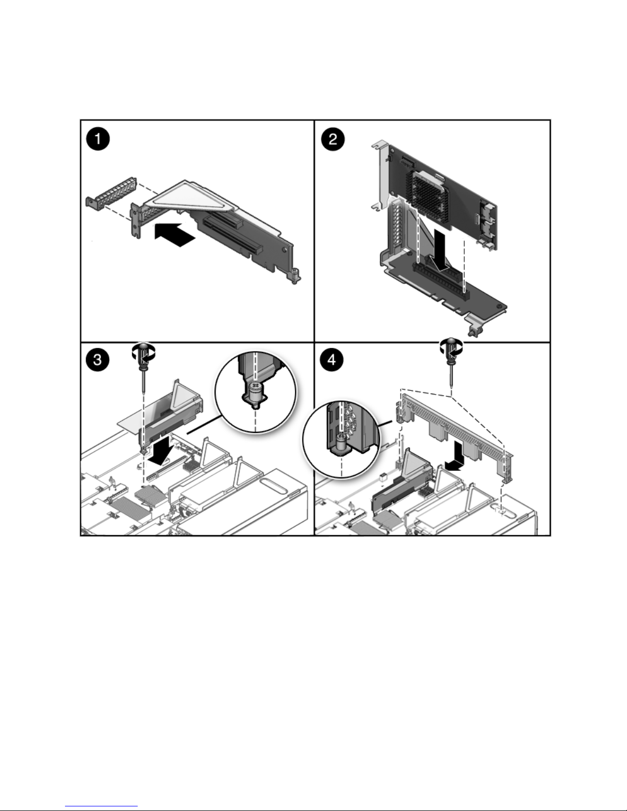
FIGURE 4-14 Installing a PCIe Card
4-30 Sun Fire X4440 Server Service Manual • September 2010

4.6 Servicing the Battery
The following topics are covered:
■ Section 4.6.1, “Removing the Battery” on page 4-32
■ Section 4.6.2, “Installing the Battery” on page 4-33
The battery maintains system time when the server is powered off and a time server
is unavailable. The battery also maintains volatile BIOS CMOS settings. If the server
fails to maintain the proper time when the server is powered off and not connected to
a network, replace the battery.
You need a small (No. 1 flat-blade) non-metallic screwdriver or equivalent.
Note – CRU: This customer-replaceable unit can be replaced by anyone.
Caution – Ensure that all power is removed from the server before removing or
installing the battery. You must disconnect the power cables from the system before
performing this procedure.
Chapter 4 Servicing Motherboard Components 4-31

FIGURE 4-15 Battery Location
4.6.1 Removing the Battery
1. Prepare the server for service.
a. Power off the server.
See Section 2.5, “Powering Off the Server” on page 2-4.
b. Disconnect the power cord (or cords) from the power supply (or supplies).
See Section 2.5, “Powering Off the Server” on page 2-4.
c. Slide the server out of the rack.
See Section 2.6, “Extending the Server to the Maintenance Position” on
page 2-5.
d. Attach an antistatic wrist strap.
See Section 2.8, “Performing Electrostatic Discharge and Antistatic Prevention
Measures” on page 2-10.
4-32 Sun Fire X4440 Server Service Manual • September 2010

e. Remove the top cover.
See Section 2.9, “Removing the Top Cover” on page 2-12.
2. Remove the PCIe riser closest to the power supply.
See Section 4.4.1, “Removing a PCIe Riser” on page 4-21.
See Section 4.5.1, “Sun Fire X4440 PCIe Card Guidelines” on page 4-25.
3. Press the latch and remove the battery from the motherboard.
Use a small (No. 1 flat-blade) non-metallic screwdriver or equivalent.
4.6.2 Installing the Battery
1. Unpack the replacement battery.
2. Press the new battery into the motherboard.
Install the positive side (+) facing upward, away from the motherboard.
3. Install the PCIe riser 0 with any associated cards.
See Section 4.4.2, “Installing a PCIe Riser” on page 4-23.
4. Return the server to operation.
a. Install the top cover.
See Section 6.1, “Installing the Top Cover” on page 6-2.
b. Slide the server into the rack.
See Section 6.3, “Returning the Server to the Normal Rack Position” on
page 6-4.
c. Reconnect the power cord (or cords) to the power supply (or supplies).
Verify that the AC Present LED is lit.
See Section 6.4, “Powering On the Server” on page 6-6.
d. Power on the server.
See Section 6.4, “Powering On the Server” on page 6-6.
5. Use the ILOM date command to set the day and time.
See the Integated Lights Out Management Guide.
Chapter 4 Servicing Motherboard Components 4-33

4.7 Servicing the Motherboard Assembly
The following topics are covered:
■ Section 4.7.1, “Removing the Motherboard Assembly” on page 4-34
■ Section 4.7.2, “Installing the Motherboard Assembly” on page 4-36
■ Section 4.7.3, “Servicetool FRU Update Procedures” on page 4-38
You must remove the motherboard assembly to access the following components:
■ Power distribution board
■ Paddle card
Note – FRU: This field-replaceable unit should be replaced only by qualified service
technicians. Contact your Sun Service representative for assistance.
Caution – Ensure that all power is removed from the server before removing or
installing the motherboard assembly. You must disconnect the power cables from the
system before performing this procedure.
Caution – This procedure requires that you handle components that are sensitive to
electrostatic discharge. This discharge can cause server components to fail. To avoid
damage, ensure that you follow the antistatic practices as described in Section 2.8,
“Performing Electrostatic Discharge and Antistatic Prevention
Measures” on page 2-10.
Caution – This procedure requires removing the server from the
rack. The server is heavy. Two people are required to remove it
from the rack.
4.7.1 Removing the Motherboard Assembly
You need a No. 2 Phillips screwdriver.
1. Prepare the server for service.
4-34 Sun Fire X4440 Server Service Manual • September 2010

a. Power off the server.
See Section 2.5, “Powering Off the Server” on page 2-4.
b. Disconnect the power cord (or cords) from the power supply (or supplies).
See Section 2.5, “Powering Off the Server” on page 2-4.
c. Remove the server from the rack.
See Section 2.7, “Removing a Server From the Rack” on page 2-8.
d. Attach an antistatic wrist strap.
See Section 2.8, “Performing Electrostatic Discharge and Antistatic Prevention
Measures” on page 2-10.
e. Remove the top cover.
See Section 2.9, “Removing the Top Cover” on page 2-12.
2. Remove the mezzanine tray.
See Section 4.2.1, “Removing the Mezzanine Tray” on page 4-13.
3. Remove the air duct.
See Section 4.3.1, “Removing the Air Duct” on page 4-16.
4. Remove the PCIe cards and risers.
See Section 4.4.1, “Removing a PCIe Riser” on page 4-21. Note the location of
expansion cards in the PCIe risers.
5. If you are replacing the motherboard, remove the mezzanine tray supports.
Use a No. 2 Phillips screwdriver.
6. Disconnect the PDB ribbon cable. (
FIGURE 4-16 [1])
See Section 5.8.7, “Removing a PDB Cable” on page 5-38.
Caution – The drive data cables are delicate. Ensure that they are safely out of the
way when servicing the motherboard.
7. Remove the 4 screws that secure the motherboard to the bus bar. [2]
Use a No. 2 Phillips screwdriver.
8. Loosen the tray attachment screw next to the chassis midwall. [2]
9. Gently slide the motherboard to the rear and carefully lift it upward. [3] Lift the
motherboard tray out of the chassis.
Move the motherboard carefully.
10. Place the motherboard assembly on an antistatic mat.
Chapter 4 Servicing Motherboard Components 4-35

FIGURE 4-16 Removing the Motherboard Assembly
4.7.2 Installing the Motherboard Assembly
Caution – This procedure requires that you handle components that are sensitive to
static discharge. Static discharge can cause component failures. To avoid damage,
ensure that you follow antistatic practices as described in Section 2.8, “Performing
Electrostatic Discharge and Antistatic Prevention Measures” on page 2-10.
1. If you are replacing the motherboard only, do the following:
a. Replace the CPUs, as required.
b. Apply thermal grease.
Follow the applicable grease procedure included with the grease.
c. Install the CPU heat sinks on the motherboard assembly, as required..
2. Place the motherboard tray into the chassis. (
■ Move the motherboard tray carefully.
4-36 Sun Fire X4440 Server Service Manual • September 2010
FIGURE 4-17 [1])
 Loading...