

Page 1

Sun Fire X4500/X4540 Server
Service Manual
Service Manual
Part No. 819-4359-19
May 2010, Revision A
Page 2

Copyright 2010 Sun Microsystems, Inc., 4150 Network Circle, Santa Clara, California 95054, U.S.A. All rights reserved.
Sun Microsystems, Inc. has intellectual property rights relating to technology that is described in this document. In particular, and without
limitation, these intellectual property rights may include one or more of the U.S. patents listed at http://www.sun.com/patents and one or
more additional patents or pending patent applications in the U.S. and in other countries.
This document and the product to which it pertains are distributed under licenses restricting their use, copying, distribution, and
decompilation. No part of the product or of this document may be reproduced in any form by any means without prior written authorization
of Sun and its licensors, if any.
Third-party software, including font technology, is copyrighted and licensed from Sun suppliers.
Parts of the product may be derived from Berkeley BSD systems, licensed from the University of California. UNIX is a registered trademark
in the U.S. and in other countries, exclusively licensed through X/Open Company, Ltd.
Sun, Sun Microsystems,the Sun logo, Java, AnswerBook2, docs.sun.com, Sun Fire, and Solarisare trademarks or registered trademarks ofSun
Microsystems, Inc., or its subsidiaries, in the U.S. and in other countries.
All SPARCtrademarks are used under licenseand are trademarks or registeredtrademarks of SPARC International,Inc. in the U.S. and in other
countries. Products bearing SPARC trademarks are based upon an architecture developed by Sun Microsystems, Inc.
AMDOpteron is a trademark or registered trademark of Advanced Microdevices, Inc.
TM
The OPEN LOOK and Sun
Graphical User Interface was developed bySun Microsystems, Inc.for its users and licensees. Sun acknowledges
the pioneering efforts of Xerox in researching and developing the concept of visual or graphical user interfaces for the computer industry. Sun
holds anon-exclusive license fromXerox tothe Xerox GraphicalUser Interface, whichlicense also covers Sun’s licensees who implement OPEN
LOOK GUIs and otherwise comply with Sun’s written license agreements.
U.S. Government Rights—Commercial use. Government users are subject to the Sun Microsystems, Inc. standard license agreement and
applicable provisions of the FAR and its supplements.
DOCUMENTATION IS PROVIDED “AS IS” AND ALL EXPRESS OR IMPLIED CONDITIONS, REPRESENTATIONS AND WARRANTIES,
INCLUDING ANY IMPLIEDWARRANTY OF MERCHANTABILITY, FITNESS FOR A PARTICULAR PURPOSEOR NON-INFRINGEMENT,
ARE DISCLAIMED, EXCEPT TO THE EXTENT THAT SUCH DISCLAIMERS ARE HELD TO BE LEGALLY INVALID.
Copyright 2010 Sun Microsystems, Inc., 4150 Network Circle, Santa Clara, Californie 95054, Etats-Unis. Tous droits réservés.
Sun Microsystems, Inc. a les droits de propriété intellectuels relatants à la technologie qui est décrit dans ce document. En particulier, et sans
la limitation, cesdroits de propriétéintellectuels peuvent inclure un ou plus des brevets américains énumérés àhttp://www.sun.com/patents
et un ou les brevets plus supplémentaires ou les applications de brevet en attente dans les Etats-Unis et dans les autres pays.
Ce produit ou document est protégé par un copyright et distribué avec des licences qui en restreignent l’utilisation, la copie, la distribution,
et la décompilation.Aucune partie de ce produit ou document nepeut être reproduite sous aucuneforme, par quelque moyenque ce soit, sans
l’autorisation préalable et écrite de Sun et de ses bailleurs de licence, s’il y en a.
Le logiciel détenu par des tiers, et qui comprend la technologie relative aux polices de caractères, est protégé par un copyright et licencié par
des fournisseurs de Sun.
Des parties de ce produit pourront être dérivées des systèmes Berkeley BSD licenciés par l’Université de Californie. UNIX est une marque
déposée aux Etats-Unis et dans d’autres pays et licenciée exclusivement par X/Open Company, Ltd.
Sun, Sun Microsystems, le logo Sun, Java, AnswerBook2, docs.sun.com, Sun Fire, et Solaris sont des marques de fabrique ou des marques
déposées de Sun Microsystems, Inc., ou ses filiales, aux Etats-Unis et dans d’autres pays.
Toutes les marques SPARC sont utilisées sous licence et sont des marques de fabrique ou des marques déposées de SPARC International, Inc.
aux Etats-Unis et dans d’autres pays. Les produits portant les marques SPARC sont basés sur une architecture développée par Sun
Microsystems, Inc.
AMDOpteron est une marque de fabrique ou une marque deposee de Advanced Microdevices, Inc.
L’interface d’utilisation graphique OPEN LOOK et Sun’ a été développée par Sun Microsystems, Inc. pour ses utilisateurs et licenciés. Sun
reconnaît les efforts de pionniers de Xerox pour la rechercheet le développement du concept des interfaces d’utilisation visuelle ou graphique
pour l’industrie de l’informatique. Sun détient une license non exclusive de Xerox sur l’interface d’utilisation graphique Xerox, cette licence
couvrant également les licenciées de Sun qui mettent en place l’interface d ’utilisation graphique OPEN LOOK et qui en outre se conforment
aux licences écrites de Sun.
LA DOCUMENTATION EST FOURNIE ’EN L’ÉTAT’ ET TOUTES AUTRES CONDITIONS, DECLARATIONS ET GARANTIES EXPRESSES
OUTACITES SONT FORMELLEMENT EXCLUES, DANS LA MESURE AUTORISEE PAR LALOI APPLICABLE, Y COMPRISNOTAMMENT
TOUTE GARANTIE IMPLICITE RELATIVE A LA QUALITE MARCHANDE, A L’APTITUDE A UNE UTILISATION PARTICULIERE OU A
L’ABSENCE DE CONTREFAÇON.
Please
Recycle
Page 3

Contents
Preface xiii
1. Introduction to the Sun Fire X4500 and X4540 Servers 1–1
1.1 Features of the Sun Fire X4500 1–1
1.1.1 System Configurations (X4500) 1–2
1.1.2 Standard I/O (X4500) 1–2
1.1.3 Summary of Features (X4500) 1–3
1.2 Features of the Sun Fire X4540 1–4
1.2.1 System Configurations (X4540) 1–4
1.2.2 Standard I/O (X4540) 1–4
1.2.3 Summary of Features (X4540) 1–5
1.3 Exterior Features, Controls, and Indicators 1–6
1.3.1 Front Panel 1–7
1.3.2 Front Panel Controls and Indicators 1–7
1.3.3 Rear Panel (X4500) 1–8
1.3.4 Rear Panel (X4540) 1–11
1.3.5 Component Locations (X4500) 1–13
1.3.6 Component Locations (X4540) 1–14
1.3.7 Sensor Information 1–15
1.4 Accessory Kit (X4500) 1–15
iii
Page 4

1.5 Accessory Kit (X4540) 1–16
1.6 Additional Options and Replaceable Components (X4500) 1–16
1.7 Additional Options and Replaceable Components (X4540) 1–18
2. Powering On and Configuring BIOS Settings 2–1
2.1 Powering On the Server 2–2
2.2 Powering Off the Server 2–3
2.3 Automatic Power-Off Events 2–3
2.4 Configuring BIOS Settings 2–4
2.4.1 Changing the Configuration of a BIOS Menu Item 2–4
2.5 Ethernet Port (NIC) Device and Driver Naming 2–5
2.5.1 NIC Naming Conventions 2–6
2.6 Power-On Self-Test (POST) 2–6
2.7 Load Optimal Default Settings During BIOS POST 2–6
2.8 BIOS Option ROM Size Limitation 2–7
2.8.1 AMD PowerNow! Feature Disabled by Default (Sun Fire X4500)
2–7
2.9 BIOS Setup Screens (X4500) 2–8
2.10 Device Boot Detection Priority (X4500) 2–10
2.11 Drives Mapping (X4500) 2–11
2.12 BIOS Setup Menu Screens (X4500) 2–12
2.12.1 BIOS Main Menu Screen (X4500) 2–13
2.12.2 BIOS Advanced Menu, Main Screen (X4500) 2–14
2.12.2.1 BIOS Advanced Menu, CPU Configuration Screen
(X4500) 2–15
2.12.2.2 BIOS Advanced Menu, IDE Configuration Screen
(X4500) 2–16
2.12.2.3 BIOS Advanced Menu, SuperIO Chipset Configuration
Screen (X4500) 2–17
2.12.2.4 BIOS Advanced Menu, ACPI Configuration Screen
iv Sun Fire X4500/X4540 Server Service Manual • May 2010
(X4500) 2–18
Page 5

2.12.2.5 BIOS Advanced Menu, Advanced ACPI Configuration
Screen (X4500) 2–19
2.12.2.6 BIOS Advanced Menu, Event Logging Details Screen
(X4500) 2–20
2.12.2.7 BIOS Advanced Menu, Hyper Transport Configuration
Screen (X4500) 2–21
2.12.2.8 BIOS Advanced Menu, IPMI 2.0 Configuration Screen
(X4500) 2–22
2.12.2.9 BIOS Advanced Menu, IPMI 2.0, View BMC Event Log
Screen (X4500) 2–23
2.12.2.10 BIOS Advanced Menu, IPMI 2.0, LAN Configuration
Screen (X4500) 2–24
2.12.2.11 BIOS Advanced Menu, IPMI 2.0, PEF Configuration
Screen (X4500) 2–25
2.12.2.12 BIOS Advanced Menu, MPS Configuration Screen
(X4500) 2–26
2.12.2.13 BIOS Advanced Menu, AMD PowerNow Configuration
(X4500) 2–27
2.12.2.14 BIOS Advanced Menu, Remote Access Configuration
Screen (X4500) 2–28
2.12.2.15 BIOS Advanced Menu, USB Configuration Screen
(X4500) 2–29
2.12.3 BIOS PCI/PnP Menu (X4500) 2–30
2.12.4 BIOS Boot Menu, Main Screen (X4500) 2–31
2.12.4.1 BIOS Boot Menu, Boot Settings Configuration Screen
(X4500) 2–32
2.12.4.2 BIOS Boot Menu, Boot Device Priority Screen (X4500)
2–33
2.12.4.3 BIOS Boot Menu, Disk Drives Screen (X4500) 2–34
2.12.4.4 BIOS Boot Menu, Removable Drives Screen (X4500) 2–
35
2.12.4.5 BIOS Boot Menu, CD/DVD Drives Screen (X4500) 2–36
2.12.5 BIOS Security Settings Menu (X4500) 2–37
2.12.6 BIOS Chipset Menu, Main Screen (X4500) 2–38
Contents v
Page 6

2.12.6.1 BIOS Chipset Menu, NorthBridge Configuration Screen
(X4500) 2–39
2.12.6.2 BIOS Chipset Menu, NorthBridge Memory
Configuration Screen (X4500) 2–40
2.12.6.3 BIOS Chipset Menu, NorthBridge ECC Configuration
Screen (X4500) 2–41
2.12.6.4 BIOS Chipset Menu, NorthBridge IOMMU
Configuration Screen (X4500) 2–42
2.12.6.5 BIOS Chipset Menu, SouthBridge Configuration Screen
(X4500) 2–43
2.12.7 BIOS Exit Options Menu Screen (X4500) 2–44
2.13 BIOS Setup Screens (X4540) 2–45
2.14 Device Boot Detection Priority (X4540) 2–47
2.15 Drives Mapping (X4540) 2–48
2.16 BIOS Setup Menu Screens (X4540) 2–50
2.16.1 BIOS Main Menu Screen (X4540) 2–51
2.16.2 BIOS Advanced Menu, Advanced Settings (X4540) 2–52
2.16.2.1 BIOS Advanced Menu, CPU Configuration (X4540) 2–
53
2.16.2.2 BIOS Advanced Menu, IDE Configuration (X4540) 2–54
2.16.2.3 BIOS Advanced Menu, Hyper Transport Configuration
(X4540) 2–55
2.16.2.4 BIOS Advanced Menu, ACPI Settings (X4540) 2–56
2.16.2.5 BIOS Advanced Settings, Advanced ACPI Settings
(X4540) 2–56
2.16.2.6 BIOS Advanced Menu, Chipset ACPI Configuration
(X4540) 2–57
2.16.2.7 BIOS Advanced Menu, General WHEA Configuration
(X4540) 2–57
2.16.2.8 BIOS Advanced Menu, Event Logging Details (X4540)
2–58
2.16.2.9 BIOS Advanced Menu, IPMI 2.0 Configuration Screen
(X4540) 2–59
vi Sun Fire X4500/X4540 Server Service Manual • May 2010
Page 7

2.16.2.10 BIOS Advanced Menu, LAN Configuration (X4540) 2–
60
2.16.2.11 BIOS Advanced Menu, IPMI 2.0, LAN Configuration
Screen (X4540) 2–61
2.16.2.12 BIOS Advanced Menu, MPS Configuration (X4540) 2–
62
2.16.2.13 BIOS Advanced Menu, PCI Express Configuration
(X4540) 2–63
2.16.2.14 BIOS Advanced Menu, Configure Remote Access
(X4540) 2–64
2.16.2.15 BIOS Advanced Menu, USB Configuration (X4540) 2–
65
2.16.3 BIOS PCI/PnP Menu (X4540) 2–66
2.16.4 BIOS Boot Settings Menu, Main Screen (X4540) 2–67
2.16.4.1 BIOS Boot Menu, Boot Settings Configuration Screen
(X4540) 2–68
2.16.4.2 BIOS Boot Menu, Boot Device Priority Screen (X4540)
2–69
2.16.4.3 BIOS Boot Menu, Disk Drives Screen (X4540) 2–69
2.16.5 BIOS Security Settings Menu (X4540) 2–70
2.16.6 BIOS Advanced Chipset Settings, Main Screen (X4540) 2–71
2.16.6.1 BIOS Advanced Chipset Settings, NorthBridge Chipset
Configuration (X4540) 2–72
2.16.6.2 BIOS Chipset Menu, NorthBridge Memory
Configuration Setting (X4540) 2–73
2.16.6.3 BIOS Chipset Menu, ECC Configuration (X4540) 2–74
2.16.6.4 BIOS Chipset Menu, DRAM Timing Configuration
(X4540) 2–75
2.16.6.5 BIOS Chipset Menu, SouthBridge Configuration Screen
(X4540) 2–76
2.16.7 BIOS Exit Options Menu Screen (X4540) 2–77
2.17 Resetting the ILOM Root Password 2–78
2.18 Using the Clear CMOS Jumper 2–83
Contents vii
Page 8

2.19 Resetting the SP 2–84
2.20 Updating BIOS 2–84
2.21 BIOS ROM Memory 2–85
2.22 Devices and PCI Slots 2–85
2.23 Disabling OPROM Scanning 2–86
3. Maintaining the Sun Fire X4500 and X4540 Servers 3–1
3.1 Tools and Supplies Needed 3–1
3.2 Locations of Components 3–2
3.3 FRUs/CRUs and BIOS Compatibility (X4540) 3–4
3.3.1 HyperTransport 3.0 Support 3–4
3.3.2 FRU/CRU Compatibility 3–5
3.3.3 Three-PSU 110V Option 3–5
3.4 System Model Numbers (X4540) 3–6
3.5 Disk Drive Compatibility 3–7
3.6 Servicetool FRU Update Procedure 3–8
3.7 Powering Off and Removing the Covers 3–10
3.7.1 Powering Off the Server 3–10
3.7.2 Removing the Server From the Rack 3–11
▼ To Remove the Server From the Rack 3-12
▼ To Remove the Drives Access Cover 3-13
▼ To Install the Drives Access Cover 3-13
3.8 Finding the I/O Board and SP MAC Addresses 3–15
3.9 Replaceable Component Procedures 3–17
3.9.1 Cable Management Arm and Cable Management Bar 3–18
3.9.2 Slide Rail Documentation 3–18
3.9.3 Replacing the Power Distribution Board (FRU) 3–18
▼ To Replace the Power Distribution Board 3-19
▼ To Replace a Fan Module (CRU) 3-25
viii Sun Fire X4500/X4540 Server Service Manual • May 2010
Page 9

▼ To Replace the Front Indicator Board (FRU) 3-28
▼ To Replace a Hard Drive (CRU) 3-31
3.9.4 Replacing a Solid-State Drive (Sun Fire X4540 CRU) 3–35
3.9.4.1 SSD Restrictions 3–36
▼ To Replace an SSD 3-36
3.9.5 Replacing a Power Supply (CRU) 3–40
▼ To Access the Third Power Supply Bay 3-41
▼ To Remove a Power Supply (CRU) 3-43
▼ To Install a Power Supply 3-44
▼ To Replace a Battery (CRU) 3-45
▼ To Replace a CPU (FRU) 3-49
▼ To Replace the GRASP Board (X4500) (FRU) 3-58
▼ To Remove Memory Modules (DIMMs) (CRU) 3-61
▼ To Install Memory Modules (DIMMs) (CRU) 3-64
▼ To Install a PCI-X or PCIe Card (FRU) 3-65
▼ To Install the System Enclosure (FRU) 3-67
3.9.6 Replacing the System Controller (FRU) 3–68
▼ To Remove the System Controller (CRU) 3-70
▼ To Install the System Controller (CRU) 3-73
A. System Specifications A–1
B. BIOS POST Codes B–1
B.1 Introduction to Power-On Self-Test (POST) B–1
B.2 How to Load Optimal Default Settings During BIOS/POST B–2
B.3 How BIOS POST Memory Testing Works B–2
B.4 Redirecting Console Output B–3
B.5 Changing POST Options B–4
B.6 POST Codes B–6
Contents ix
Page 10

B.7 POST Code Checkpoints B–8
C. Status Indicator LEDs C–1
C.1 Front Panel LEDs C–2
C.1.1 Rear Panel LEDs C–4
C.2 Disk Drive and Fan Tray LEDs C–6
C.2.1 CPU Board LEDs C–10
C.3 GRASP Board LED (Sun Fire X4500) C–13
C.4 CPU Module Debug LEDs C–15
D. Connector Pinouts D–1
D.1 USB Connector D–1
D.2 Serial Connector D–2
D.3 10/100BASE-T Connector D–3
D.4 10/100/1000BASE-T Connector D–4
D.5 VGA Video Connector D–5
D.6 I/O-to-Disk Backplane Connectors D–6
D.7 Power Supply Connector D–13
D.8 Disk Backplane to Front Indicator Connector D–14
D.9 Backplane To Disk Backplane Connector D–15
D.10 Fan Tray Connectors D–16
D.11 Fan Connectors D–17
E. Power Reset and Initialization Sequences E–1
E.1 Power-On Reset Sequence E–1
E.2 Power-Off Sequence E–4
F. I2E Bus Devices F–1
F.1 Power-On Reset Sequence F–1
F.2 I2E Bus Address Table F–1
x Sun Fire X4500/X4540 Server Service Manual • May 2010
Page 11

G. Early-Production Slide Rail and CMA Information G–1
G.1 Removing the Cable Management Arm for the X4500 G–1
G.2 Removing the Cable Management Arm for the X4500 G–3
H. Device Paths H–1
H.1 Sun Fire X4500 Device Paths H–1
H.2 Sun Fire X4540 Device Paths H–3
Index Index–1
Contents xi
Page 12

xii Sun Fire X4500/X4540 Server Service Manual • May 2010
Page 13

Preface
This Sun Fire X4500/X4540 Service Manual contains information and procedures for
maintaining and upgrading the server, including the system BIOS.
Related Documentation
All Sun hardware documentation is available at:
http://docs.sun.com/
For the most up-to-date information about the product name, navigate to the product
name document collection using the High-End Servers and Blade Servers product
category links.
Translated versions of some of these documents might also be available after the
product’s world-wide release date. Select a language from the drop-down list and
browse or navigate to the product name x64 document collection. Available
translations for the Sun Fire servers include Simplified Chinese, Traditional Chinese,
French, Japanese, and Korean.
English documentation is revised more frequently and might be more up-to-date
than the translated documentation.
xiii
Page 14

Documentation, Support, and Training
The Sun web site provides information about the following additional resources:
Sun Function URL
Documentation http://www.sun.com/documentation
Support http://www.sun.com/support/index.jsp
Training http://www.sun.com/training/
Warranty http://www.sun.com/service/support/warranty/index.html
Sun Welcomes Your Comments
Sun is interested in improving its documentation and welcomes your comments and
suggestions. You can submit your comments by going to:
http://www.sun.com/hwdocs/feedback
Include the title and part number of your document with your feedback: Sun Fire
X4500/X4540 Server, 819-4359-19.
xiv Sun Fire X4500/X4540 Server Service Manual • May 2010
Page 15

CHAPTER
1
Introduction to the Sun Fire X4500
and X4540 Servers
This chapter contains an overview of the Sun Fire™ X4500 and X4540 servers,
including features and orderable components.
This chapter contains the following procedures and information:
■ Section 1.1, “Features of the Sun Fire X4500” on page 1-1
■ Section 1.2, “Features of the Sun Fire X4540” on page 1-4
■ Section 1.3, “Exterior Features, Controls, and Indicators” on page 1-6
■ Section 1.4, “Accessory Kit (X4500)” on page 1-15
■ Section 1.5, “Accessory Kit (X4540)” on page 1-16
■ Section 1.6, “Additional Options and Replaceable Components (X4500)” on
page 1-16
■ Section 1.7, “Additional Options and Replaceable Components (X4540)” on
page 1-18
1.1 Features of the Sun Fire X4500
The Sun Fire X4500 server is a mid-level, modular, rack-optimized server in the Sun
x64 product family; the family platform includes servers engineered for AMD
Opteron CPUs and deployment into commercial server markets in a slide-mounted,
horizontally biased enclosure for rack cabinet installations, primarily in datacenter
locations.
1-1
Page 16

1.1.1 System Configurations (X4500)
The server provides the following maximum system configurations:
■ 8 DDR-I DIMM slots (4 per processor), up to 2 GB per DIMM (16 GB per system)
■ Up to forty-eight 3.5-inch SATA-I disk drives of 250 to 1 TB capacity each (48 TB
total system capacity)
■ Two 133-MHz PCI-X slots
1.1.2 Standard I/O (X4500)
The standard I/O for the Sun Fire X4500 is:
■ Four 10/100/1000 BASE-T Gigabit Ethernet ports
■ VGA video port
■ Serial management port
■ Four USB ports
■ One 10/100BASE-T Ethernet management port
The Sun Fire X4500 server includes an extensive set of reliability, availability, and
serviceability (RAS) features, such as:
■ Hot-pluggable and redundant disk drives
■ Hot-swappable fans
■ Hot-swappable power supplies
The servers also provide an Integrated Lights Out Management (ILOM) service
processor function that includes remote boot and remote software upgrades.
1-2 Sun Fire X4500/X4540 Server Service Manual • May 2010
Page 17

1.1.3 Summary of Features (X4500)
TABLE 1-1 summarizes the features of the Sun Fire X4500 server.
TABLE 1-1 Summary of Features (X4500)
Feature or
Component Sun Fire X4500 Server
CPU Two Revision E AMD64 Opteron quad-core processors on two CPU
modules.
Processor BIOS 8 Mbit Flash memory with LPC interface.
Memory 8 DDR-I DIMM slots (4 per processor), up to 2 GB per DIMM (16 GB per
system).
Disk drives Up to forty-eight 3.5-inch SATAType-1 disk drives of 250 to 1 TB
capacity each (48 TB total system capacity).
Service Processor SP card mounted on video card in PCI slot that runs Integrated Lights
Out Manager (ILOM) as described in the ILOM documentation (see
“Related Documentation” on page xiii).
Network I/O • Four 10/100/1000BASE-T Gigabit Ethernet ports (RJ-45 connectors)
• One 10/100BASE-T Ethernet net management port (RJ-45 Connector)
• One RS-232 serial port (RJ-45 Connector)
PCI I/O Two available PCI-X slots (x8), LSI SAS 1068E. (Third slot is reserved for
a video card that system boots off until host software boots.)
• Six SATA Controllers on IO Board, LSI SATA controller x 6. Each
controller supports 8 drives
• 51.5 mm (2.5 inches) maximum height
• 169.3 mm (6.7 inches) maximum length
Other I/O • Four USB 2.0 ports
• One VGA video port (D-15 connector)
Power 1500 W DC max output per power supply, two bays, 1+1 redundancy,
hot-swappable.
1130 W AC max system input power = 3856 BTU/hr = 0.321 Tons of Air
Conditioning, 200–240 VAC.
Fans Five fan modules; also additional fans in each power supply.
Cooling is front-to-back forced air.
Chapter 1 Introduction to the Sun Fire X4500 and X4540 Servers 1-3
Page 18

1.2 Features of the Sun Fire X4540
The Sun Fire X4540 server is a mid-level, modular, rack-optimized server in the Sun
x64 product family; the family platform includes servers engineered for AMD
Opteron CPUs and deployment into commercial server markets in a slide-mounted,
horizontally biased enclosure for rack cabinet installations, primarily in datacenter
locations.
1.2.1 System Configurations (X4540)
The server provides the following maximum system configurations:
■ 16 DDR-II DIMM slots (8 per processor) 64GB maximum with 2 CPUs and 4 GB
DIMMs, standard 32GB
■ Up to forty-eight 3.5-inch SATA-II disk drives of 250 - 1TB capacity (48 TB total
system capacity)
■ Three x8 PCIe slots
■ Supports solid-state drives
1.2.2 Standard I/O (X4540)
■ Four 10/100/1000 BASE-T Gigabit Ethernet ports
■ Three PCIe ports
■ VGA video port
■ Four USB 2.0 ports (2 front, 2 rear)
■ One 10/100BASE-T Ethernet management port
■ Compact Flash slot
■ Serial management port (R45, no LEDs)
The Sun Fire X4540 server includes an extensive set of reliability, availability, and
serviceability (RAS) features, such as:
■ Hot-pluggable and redundant disk drives and SSDs
■ Hot-swappable fans
■ Hot-swappable power supplies
■ Hot-swappable SATA disk drives
1-4 Sun Fire X4500/X4540 Server Service Manual • May 2010
Page 19

The servers also provide an Integrated Lights-Out Management (ILOM) service
processor function that includes remote boot and remote software upgrades.
1.2.3 Summary of Features (X4540)
TABLE 1-2 summarizes the features of the Sun Fire X4540 server.
TABLE 1-2 Summary of Features (X4540)
Feature or
Component Sun Fire X4540 Server
CPU Two 2000 Series quad-core AMD Opteron Processor, 2-socket
configuration.
Two 8000/2000 Series six-core AMD Opteron Processor
Processor BIOS STMicro 8 Mbit Flash memory with LPC interface.
Memory 16 DDR-II DIMM slots (8 per processor), up to 4 GB per DIMM (64 GB
per system).
Disk drives Up to 48 250MB to 1 TB capacity, 3.5-inch SATA Type-I and II drives (48
TB total system capacity).
One to eight 3.5” SATA SSDs.
Solid-state drives
(SSD)
Service Processor SP circuitry running Integrated Lights Out Manager (ILOM) as
Network I/O • Four 10/100/1000BASE-T Ethernet ports (RJ-45 connectors)
Serial port • RS-232 serial interface (RJ45 connector, no LEDs)
One to eight 32-GB, 3.5-inch, SATA SSDs can be installed into the
system.
described in the ILOM documentation (see “Related Documentation” on
page xiii).
• One 10/100BASE-T Ethernet net management port (RJ-45 Connector)
• One RS-232 serial port (RJ-45 Connector)
• Four (4) USB 2.0 Ports (Type A Connector) (2x in front and 2x in rear)
• Video Port (D-15 VGA Connector)
• CF Type-I or Type-II slot
• Console only, no modem support (no RI, PPP)
• Connected to ILOM by default
• Default parameters
9600 baud
8 data bits
No parity
1 stop bit
No flow control
Chapter 1 Introduction to the Sun Fire X4500 and X4540 Servers 1-5
Page 20

TABLE 1-2 Summary of Features (X4540)
Feature or
Component Sun Fire X4540 Server
PCIe I/O Three low-profile x8 PCIe slots.
Other I/O • Four USB 2.0 ports
• One VGA video port (D-15 connector on controller)
• Compact Flash card slot
Power • 1500 W DC max output per power supply, two bays, 1+1 redundancy,
hot-swappable.
• 1000 Watts max input power (3412 BTU/h =Maximum air flow is 200
CFM maximum air flow.
• 5 Amps max operating current @ 220 VAC (198 VAC to 264 VAC
range), 50 to 60 Hz.
Fans • Five fan modules; also additional fans in each power supply.
• Cooling is front-to-back forced air. Hot swappable, Variable speed,
• 7500 R.P.M. max, Top loading, Fault/OK LEDs,1.8A/18W,
SATAconnector.
• The SP software controls the fan speed and detects fan failure.
Operation terminates if a fan tray is removed.
Note - Do not operate the system with a fan removed for more than 60
seconds
1.3 Exterior Features, Controls, and
Indicators
This section shows, lists, and describes the features and the controls and indicators
on the front and rear panels of the Sun Fire X4500/X4540 server.
Note – For a quick and concise description of these features refer to the service label
located on the hard drive access cover.
This section contains the following procedures and information:
■ Section 1.3.1, “Front Panel” on page 1-7
■ Section 1.3.2, “Front Panel Controls and Indicators” on page 1-7
■ Section 1.3.3, “Rear Panel (X4500)” on page 1-8
■ Section 1.3.4, “Rear Panel (X4540)” on page 1-11
■ Section 1.3.5, “Component Locations (X4500)” on page 1-13
1-6 Sun Fire X4500/X4540 Server Service Manual • May 2010
Page 21
■ Section 1.3.6, “Component Locations (X4540)” on page 1-14
■ Section 1.3.7, “Sensor Information” on page 1-15
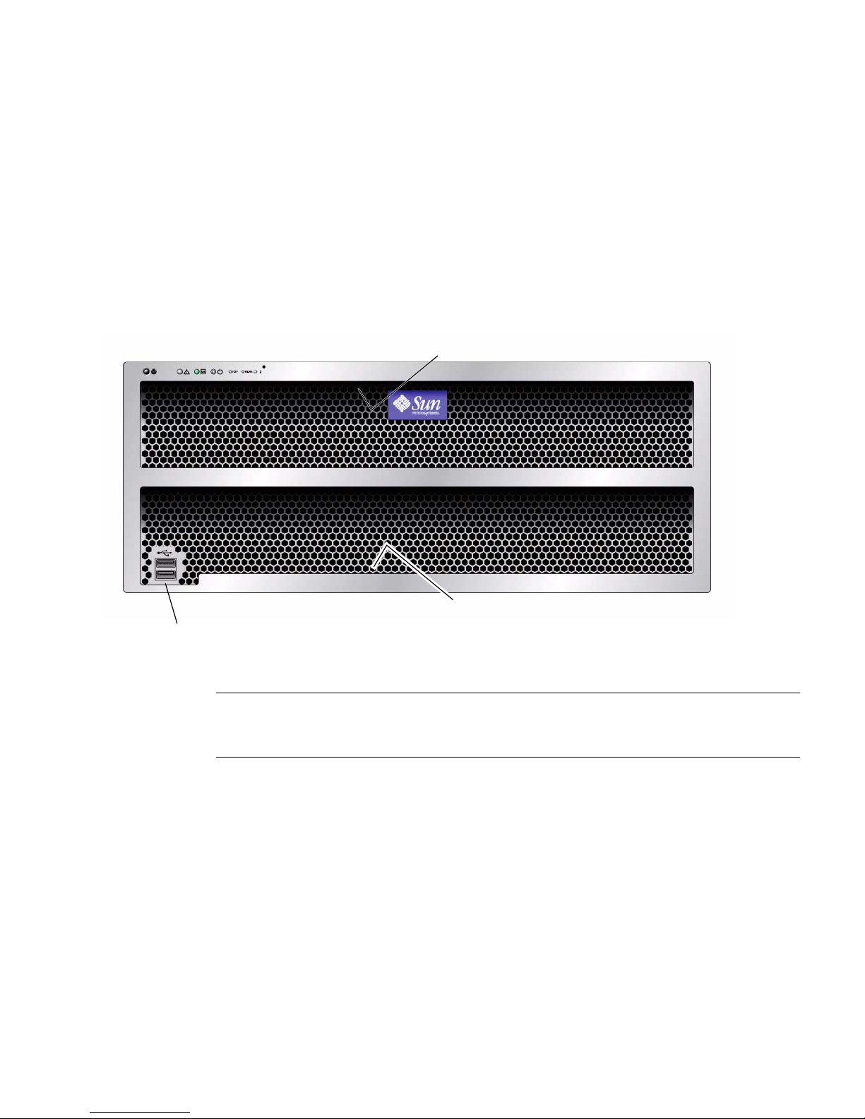
1.3.1 Front Panel
FIGURE 1-1 shows the front panel.
FIGURE 1-1 Sun Fire X4500/X4540 Server Front Panel Features
1
3
2
Figure Legend
1 Serial number label
2 Two USB 2.0 connectors
3 Serial number label
1.3.2 Front Panel Controls and Indicators
FIGURE 1-2 shows a close up of the controls and indicators.
For more on LED behavior, see “Status Indicator LEDs” on page C-1.
Chapter 1 Introduction to the Sun Fire X4500 and X4540 Servers 1-7
Page 22

FIGURE 1-2 Controls and Indicators
1435672
1.3.3 Rear Panel (X4500)
Figure Legend
1 Locate button/LED
2 System Fault LED
3 Power/OK LED
4 System power button
5 Top fault LED
6 Rear fault LED
7 System Over Temperature
FIGURE 1-3 shows the features of the rear panel. TABLE 1-3 lists and describes each
feature.
1-8 Sun Fire X4500/X4540 Server Service Manual • May 2010
Page 23

FIGURE 1-3 Sun Fire X4500 Rear Panel
12 3 54
11 1210 13 14 15 1667 8 9
TABLE 1-3 Figure Legend—Sun Fire X4500 Rear Panel Features
# Name Description
1 Power Supply LED
(amber)
Steady on—Fault. Service action required.
Off—No fault.
2 Power Supply LED (green) Steady on—Power is on (AC/DC are OK).
Blinking —Blinks briefly once every 3 seconds. Standby
power is on (AC is OK).
Off — Power is off.
3 AC power connector Each power supply has its own AC connector with a
clip to secure its power cable.
4 Chassis ground To connect grounding straps
5 Mounting plate for (Cable
Management Assembly)
CMA bracket
To secure the CMA, as described in the Sun X4500-J Slide
Rail Installation Guide or the Sun Fire X4500 Server Getting
Started Guide.
6 PCI-X-0 and PCI-X-1 Two slots for PCI-X cards.
7 Network management port NET MGT — Net management and service processor
10/100 Mbit/sec Ethernet port.
8 Video connector VGA port to connect video monitor.
Chapter 1 Introduction to the Sun Fire X4500 and X4540 Servers 1-9
Page 24

TABLE 1-3 Figure Legend—Sun Fire X4500 Rear Panel Features
# Name Description
9 Serial management port SER MGT—RJ45 serial management port (serial
connection to service processor).
10 Locate button/LED (white) Toggles on/off locally—Operators can turn on this on
remotely to help them locate the enclosure in a crowded
server room. Press to turn off.
11 System Fault LED (amber) Off—Normal operation
On—Service action is required.
A system running under these conditions are in a fault
condition, but the SP does not log the reason the service
LED is illuminated:
• 220VAC with only 1 PSU
• 110VAC with only two PSUs
12 System Status LED (green) Steady on— Power is on and system is operational.
Blinking—Standby power is on but main power is off.
Blinks briefly once every 3 seconds.
Off — Power is off.
13 USB ports To connect USB 2.0 devices.
14 10/100/1000 Gigabit
To connect server to Ethernet.
Ethernet ports
15 System Controller status
LEDs
Blue — Ready to remove (service action allowed)
Amber — Fault (Service action required)
Green — OK (no action required)
16 Reset buttons Caution - Do not use these buttons unless instructed to
do so by Sun service personnel. To operate these buttons,
insert a nonconducting stylus into the recess.
• SP — Service Processor.
• HOST – This button resets the CPU but not the service
processor.
1-10 Sun Fire X4500/X4540 Server Service Manual • May 2010
Page 25

1.3.4 Rear Panel (X4540)
Note – For a quick and concise description of these actions refer to the service label
located on the hard drive access cover.
FIGURE 1-4 shows the features of the rear panel. TABLE 1-4 lists and describes each
feature.
FIGURE 1-4 Sun Fire X4540 Server Rear Panel
1 2 3 54
1210 13 15 16 17
6
TABLE 1-4 Sun Fire X4540 Rear Panel Features
# Name Description
1 Power Supply Fault LED
(amber)
2 Power Supply LED (green) Steady on—Power is on (AC/DC are OK).
3 AC power connectors Each power supply has its own AC connector with a clip
11
When on, service action is required.
Blinking—Standby power is on (AC is OK). Blinks briefly
every 3 seconds.
Off—Power is off.
to secure its power cable.
Chapter 1 Introduction to the Sun Fire X4500 and X4540 Servers 1-11
147 98
Page 26

TABLE 1-4 Sun Fire X4540 Rear Panel Features
# Name Description
4 Chassis ground To connect grounding straps.
5 Mounting plate Only for mounting CMA on X4500.
6 PCIe Three slots for X-option cards.
7 Locate button/LED (white) Toggles on/off locally—Operators can turn on this LED
remotely to help them locate the server in a crowded
server room. Press to turn off.
8 Fault LED Amber—When on, service action is required.
Off—No faults present.
9 Enclosure OK LED (green) Steady on— Power is on and system is operational.
Blinking—Standby power is on but main power is off.
Blinks briefly once every 3 seconds.
Off — Power is off.
10 Reset buttons Caution - Do not use these buttons unless instructed to
do so by Sun service personnel. To operate these buttons,
insert a nonconducting stylus or a straightened paper
clip into the recess.
• SP — Service Processor.
• NMI – Non-Maskable Interrupt dump. This button
sends an NMI to the CPU. It is used for debugging
purposes only. (Supported on Windows platforms
only.)
• HOST – This button resets the CPU but not the service
processor.
11 System controller status
LEDs
Blue – Ready to remove (service action allowed).
Amber – Fault (service action required).
Green – Operational (no action required).
12 Serial management port SER MGT—Serial management port (serial connection to
service processor).
13 Network management port NET MGT — Net management and service processor
10/100 Mbit/sec Ethernet port.
14 10/100/1000 Gigabit
To connect server to Ethernet.
Ethernet ports
15 USB connectors To connect USB 2.0 devices.
16 Video connector VGA port to connect video monitor.
17 Compact Flash (CF) card Slot to insert Compact Flash card. Push once and button
comes out. Push second time and card ejects.
1-12 Sun Fire X4500/X4540 Server Service Manual • May 2010
Page 27

FIGURE 1-5 shows the locations of the Sun Fire X4540 server components, with the
covers removed.
1.3.5 Component Locations (X4500)
FIGURE 1-5 Sun Fire X4500 Component Locations
CMA mounting plate
System Controller (not
visible under power
supplies) contains:
- CPUs (2)
- DIMMs (4 per CPU)
- Battery
- Service Processor
- PCI-X slots (2)
Power supplies (2)
Power distribution
board (not visible --
under power supplies)
Disk drives (48)
ESD ground
strap connection
Drives backplane
(not visible -- under
chassis plate)
Front indicator board
(not visible -- under fan)
Fan modules (5)
Front bezel
Chapter 1 Introduction to the Sun Fire X4500 and X4540 Servers 1-13
Page 28

1.3.6 Component Locations (X4540)
FIGURE 1-6 Sun Fire X4540 Component Locations
Power supplies (2)
System Controller (not
visible under power
supplies) contains:
- CPUs (2)
- DIMMs (8 per CPU)
- Battery
- Service Processor
- PCIe slots (3)
Disk drives (48)
ESD ground
strap connection
Drives backplane
(not visible -- under
chassis plate)
Power distribution
board (not visible --
under power supplies)
Front indicator board
(not visible -- under fan)
1-14 Sun Fire X4500/X4540 Server Service Manual • May 2010
Fan modules (5)
Front bezel
Page 29

1.3.7 Sensor Information
Information on the location of the server’s sensors can be found in Sun Fire™
X4500/X4540 Servers Diagnostics Guide, 819-4363.
For information on sensors that report on hardware conditions, see Sun™ Integrated
Lights Out Manager 3.0 Supplement for Sun Fire X4540 Server, 820-5549-10.
1.4 Accessory Kit (X4500)
TABLE 1-5 lists the contents of the accessory kit that is shipped with the Sun Fire
X4500 server.
Note – Because of Sun’s commitment to eco-responsibility, we are not shipping a
printed installation guide and software CDs for the new Sun Fire X4540 Server.
Customers can order the documentation and CDs through the SunStore or Sun sales
support representative. The Installation Guide and software are also available on the
Web at no charge.
TABLE 1-5 Sun Fire X4500 Accessory Kit
Item
Bootable Diagnostics CD
Sun Fire X4500 Where To Find (printed manual)
Serial-to-RJ45 cable adapter (DB9S-to-RJ-45F)
Sun Fire X4500 Installation Guide (printed manual)
Sun Fire X4500 Tools and Drivers CD
Sun Installation Assistant CD
Important Safety Information for Sun Hardware Systems (printed manual)
Software License Agreement (printed manual)
Chapter 1 Introduction to the Sun Fire X4500 and X4540 Servers 1-15
Page 30

1.5 Accessory Kit (X4540)
TABLE 1-6 lists the contents of the accessory kit that is shipped with the Sun Fire
X4540 server.
TABLE 1-6 Sun Fire X4540 Accessory Kit
Item
Sun Fire X4540 Getting Started Guide (printed manual)
Serial-to-RJ45 cable adapter (DB9S-to-RJ-45F)
Important Safety Information for Sun Hardware Systems (printed manual)
Software License Agreement (printed manual)
1.6 Additional Options and Replaceable
Components (X4500)
TABLE 1-7 lists the after-factory options and replaceable components for the Sun Fire
X4500 server. Whether the items are customer-replaceable units (CRUs) or
field-replaceable units (FRUs) is indicated in the last column of the table.
Supported components and their part numbers are subject to change over time. For
the most up-to-date list of replaceable components, product updates, and downloads,
see the following URL:
http://sunsolve.sun.com/handbook_pub/Systems/
1-16 Sun Fire X4500/X4540 Server Service Manual • May 2010
Page 31

TABLE 1-7 Sun Fire X4500 Replaceable Components
Component Part Number
CRU
or
FRU
Power Supply #300-1787,
CRU
X4502A-Z (X-option)
Fan Module (5 Fan Modules/system) #541-0458 CRU
Seagate Galaxy 250GB #541-1468 CRU
Hitachi Kurafone2 500GB #541-1467 CRU
Hitachi GeminiK 500GB #541-3050 CRU
Hitachi GeminiK 750GB #540-7244 CRU
Hitachi GeminiK 1TB #540-7507 CRU
2-GB DIMMs, Pair (2 DIMMs, 4 GB total) Registered
ECC Memory, 8 slots/system
#541-1903
X4231A-Z (X-option)
CRU
GRASP board (includes SP board and video board) #541-2963 FRU
CPU (AMD 290, 2.8-GHz dual core), includes grease #371-1779 FRU
System Controller Assembly (with I/O controller
#541-1915 FRU
board and CPU board; without CPUs, DIMMs, and
GRASP board.)
Front Indicator Board (FIB) with ribbon cable #501-7192 FRU
System Enclosure Super FRU (includes disk backplane
#541-1907 FRU
and FIB with ribbon cable)
Power Distribution Board (220 VAC) #501-7104 FRU
Battery #150-3993 CRU
Rack Mount X-Options
Cable Management Arm #371-2887,
FRU
X4229A-Z (X-option)
Slide Rail Kit (JES) #371-3493,
FRU
X4228A-Z (X-option)
Chapter 1 Introduction to the Sun Fire X4500 and X4540 Servers 1-17
Page 32

1.7 Additional Options and Replaceable
Components (X4540)
TABLE 1-8 lists the after-factory options and replaceable components for the Sun Fire
X4540 server. Whether the items are customer-replaceable units (CRUs) or
field-replaceable units (FRUs) is indicated in the last column of the table.
Supported components and their part numbers are subject to change over time. For
the most up-to-date list of replaceable components, product updates, and downloads,
see the following URL:
http://sunsolve.sun.com/handbook_pub/Systems/
Click the name and model of your server, and then click the Full Components List for
the list of components and part numbers.
TABLE 1-8 Sun Fire X4540 Replaceable Components
Component Marketing Part Number CRU or FRU
Power supply (type A205), 1500W (X4500, 2 or 3 per
system)
Fan Module (5 Fan Modules/system) #341-0458 CRU
Seagate 250GB #541-3678,
Hitachi 500GB #541-3050,
Hitachi 1TB #540-7507,
Seagate 500GB #541-3679 CRU
Seagate 1TB #541-3730 CRU
32GB 3.5" SATA SSD #541-4077,
2 DIMMs x 2GB, 512Mb-based, dual-rank DIMMs
(4 GB total) registered ECC Memory, 16 slots/system
2 DIMMs x 2GB, 1Gb-based, single-rank DIMMs
(8 GB total) registered ECC Memory, 16 slots/system
#300-1787,
X4502A-Z (X-option)
XRA-ST1CH-250G7KZ
(X-option)
XRA-ST1CH-500G7KZ
(X-option)
XRA-ST1CH-1T7K
(X-option)
XRA-ST1CH-32G2SSD
(X-option)
#541-1313
X5034 (X-option)
#541-3360
X4540 (X-option)
CRU
CRU
CRU
CRU
CRU
CRU
CRU
1-18 Sun Fire X4500/X4540 Server Service Manual • May 2010
Page 33

TABLE 1-8 Sun Fire X4540 Replaceable Components
Component Marketing Part Number CRU or FRU
2 DIMMs x 4GB, 1Gb-based, single-rank DIMMs
(8 GB total) registered ECC Memory, 16 slots/system
2 DIMMs x 8GB, 2Gb-based, single-rank DIMMs
(8 GB total) registered ECC Memory, 16 slots/system
System Controller Assembly with I/O controller board
#541-1304
CRU
X5035 (X-option)
#541-3419
CRU
X8356A (X-option)
#541-0491 FRU
and CPU board; without CPUs, DIMMs, and GRASP
board. (Only compatible with quad-core 2356
processor.)
System Controller Assembly with I/O controller board
#541-3758 FRU
and CPU board; without CPUs, DIMMs, and GRASP
board. (Compatible with quad-core 2356 or 2384
processor.)
Graphics Service Processor (GRASP) board, includes
#541-0597 FRU
SP board and video board
CPU (quad core 2.3 GHz 2356 processor) #371-4042 FRU
CPU (quad core 2.7 GHz 2384 processor) #371-4438 FRU
Front Indicator Board (FIB) with ribbon cable #501-7192 FRU
System Enclosure Super FRU with disk backplane and
#541-1218 FRU
FIB with ribbon cable
System Controller Upgrade Kit (includes I/O
controller board (USB) and CPU board, 2x2356,
B24-FSZ2-4540-CONT
(X-option)
CRU
16x2GB (1GB), and document)
System Controller Upgrade Kit (includes I/O
controller board (USB) and CPU board, 2x2435,
B24-BZ2-4540-CONT
(X-option)
CRU
16x2GB (1GB), and document)
Power Distribution Board (220 VAC) #501-7104 FRU
Battery #150-3993 CRU
Rack Mount X-Options
Slide Rail Kit #350-1393,
FRU
X4541 (X-option)
Cable Management Arm (compatible only with Slide
Rail Kit #371-3493)
New Cable Management Arm with Cable Management
Bar (compatible only with Slide Rail Kit #350-1393)
#371-2887,
X4229A-Z (X-option)
#350-1363,
X4542 (X-option)
FRU
FRU
Chapter 1 Introduction to the Sun Fire X4500 and X4540 Servers 1-19
Page 34

1-20 Sun Fire X4500/X4540 Server Service Manual • May 2010
Page 35

CHAPTER
2
Powering On and Configuring BIOS
Settings
This chapter contains the following procedures and information.
■ Section 2.1, “Powering On the Server” on page 2-2
■ Section 2.2, “Powering Off the Server” on page 2-3
■ Section 2.3, “Automatic Power-Off Events” on page 2-3
■ Section 2.4, “Configuring BIOS Settings” on page 2-4
■ Section 2.5, “Ethernet Port (NIC) Device and Driver Naming” on page 2-5
■ Section 2.6, “Power-On Self-Test (POST)” on page 2-6
■ Section 2.7, “Load Optimal Default Settings During BIOS POST” on page 2-6
■ Section 2.8, “BIOS Option ROM Size Limitation” on page 2-7
■ Section 2.9, “BIOS Setup Screens (X4500)” on page 2-8
■ Section 2.10, “Device Boot Detection Priority (X4500)” on page 2-10
■ Section 2.11, “Drives Mapping (X4500)” on page 2-11
■ Section 2.12, “BIOS Setup Menu Screens (X4500)” on page 2-12
■ Section 2.13, “BIOS Setup Screens (X4540)” on page 2-45
■ Section 2.14, “Device Boot Detection Priority (X4540)” on page 2-47
■ Section 2.15, “Drives Mapping (X4540)” on page 2-48
■ Section 2.16, “BIOS Setup Menu Screens (X4540)” on page 2-50
■ Section 2.17, “Resetting the ILOM Root Password” on page 2-78
■ Section 2.18, “Using the Clear CMOS Jumper” on page 2-83
■ Section 2.19, “Resetting the SP” on page 2-84
■ Section 2.20, “Updating BIOS” on page 2-84
■ Section 2.21, “BIOS ROM Memory” on page 2-85
■ Section 2.22, “Devices and PCI Slots” on page 2-85
2-1
Page 36

■ Section 2.23, “Disabling OPROM Scanning” on page 2-86
2.1 Powering On the Server
Before powering on your server for the first time, follow the installation and cabling
instructions provided in the Sun Fire X4540 Installation Guide, available online at the
URL described in “Related Documentation” on page xiii.
Caution – Do not operate the server without all fans, component heat sinks, air
baffles, and the cover installed. Severe damage to server components can occur if the
server is operated without adequate cooling mechanisms.
To power on main power for all server components:
1. Verify that power cords have been connected and that standby power is on.
In standby power mode, the Power/OK LED (3) on the front panel flashes.
FIGURE 2-1 Front Panel Controls and Indicators
1435672
1 Locate button/LED
2 Alert LED
3 Power/OK LED (system power)
4 Power button
2-2 Sun Fire X4500/X4540 Server Service Manual • May 2010
Page 37

5 Top (disk drive or fan fault)
6 Rear (power supply or system controller fault)
7 System over temperature
2. Use a nonconducting stylus to press and release the recessed Power button on
the server front panel. See
When main power is applied to the full server, the Power/OK LED next to the
Power button lights and remains lit.
FIGURE 2-1.
2.2 Powering Off the Server
To power off the server from main power mode, use one of the following two
methods:
■ Graceful shutdown: Use a nonconducting stylus to press and release the Power
button on the front panel. This causes Advanced Configuration and Power
Interface (ACPI) enabled operating systems to perform an orderly shutdown of
the operating system. Servers not running ACPI-enabled operating systems will
shut down to standby power mode immediately.
■ Emergency shutdown: Press and hold the Power button for four seconds to force
main power off and enter standby power mode.
When main power is off, the Power/OK LED on the front panel will begin
blinking, indicating that the server is in standby power mode.
Caution – To power off the server completely, you must disconnect the AC power
cords from the back panel of the server.
2.3 Automatic Power-Off Events
The service processor shuts down the system if it detects an overtemperature
condition.
The hardware shuts down the system immediately if any voltage is out of spec, or if
the last working power supply fails.
See Section E.2, “Power-Off Sequence” on page E-4 for a diagram of the power-off
sequence and its timing parameters.
Chapter 2 Powering On and Configuring BIOS Settings 2-3
Page 38

2.4 Configuring BIOS Settings
This section describes how to view and modify the BIOS settings.
The Basic Input/Output System (BIOS) has a Setup utility stored in the BIOS flash
memory. The Setup utility reports system information and can be used to configure
the BIOS settings. The configured data is provided with context-sensitive Help and is
stored in the system's battery-backed CMOS RAM. If the configuration stored in the
CMOS RAM is invalid, the BIOS settings default to the original state specified at the
factory.
When the BIOS is started, the first BIOS Setup menu screen is displayed. The BIOS
Setup utility contains seven menu screens, which are displayed in this order: Main,
Advanced, PCI/PnP, Boot, Security, Chipset, and Exit.
■ Use the left and right arrow keys to move sequentially back and forth through the
seven screens (Fields that can be reconfigured are displayed in color. All other
fields are nonconfigurable.)
■ Use the up and down arrows, on the keyboard, to scroll through a menu.
■ Use the Tab key to move back and forth across columns.
2.4.1 Changing the Configuration of a BIOS Menu Item
You can change the BIOS configuration in several different interfaces:
■ Use a USB keyboard and mouse, and a VGA monitor connected directly to the
server.
■ Use the remote video console of the ILOM Service Processor and redirect the
server’s console output. See Section B.4, “Redirecting Console Output” on
page B-3.
■ Use a terminal (or terminal emulator connected to a computer) through the serial
port on the back panel of the server.
To change the system’s parameters:
1. Enter the BIOS Setup utility by pressing the F2 key while the system is
performing the power-on self-test (POST).
2. Highlight the field to be modified using the arrow and Tab keys.
3. Press Enter to select the field.
A dialog box appears. The box presents you with the options available for the
setup field that you have chosen.
2-4 Sun Fire X4500/X4540 Server Service Manual • May 2010
Page 39

4. Modify the setup field and close the screen.
5. If you need to modify other setup parameters, use the arrow and Tab keys to
navigate to the desired screen and menu item, then repeat Steps 1 through 3.
Otherwise, go to Step 5.
6. Press and release the right arrow key until the Exit menu screen is displayed.
7. Follow the instructions on the Exit menu screen to save your changes and exit
the Setup utility.
2.5 Ethernet Port (NIC) Device and Driver
Naming
These servers each have four 10/100/1000BASE-T Gigabit Ethernet ports connected
to individual Network Interface Cards (NICs). The chassis labeling of the physical
ports is shown in
FIGURE 1 Ethernet Port Chassis Labeling Designations
FIGURE 1.
NET 2 NET 3
NET 0 NET 1
The logical device naming for the NICs is reported differently by different interfaces
and operating systems.
Chapter 2 Powering On and Configuring BIOS Settings 2-5
Page 40

2.5.1 NIC Naming Conventions
See FIGURE 2 for a diagram that explains how operating systems and interfaces name
the four NICs shown in
FIGURE 2 Sun Fire X4500 NIC Naming Conventions
BIOS Solaris 10 Red Hat Linux
FIGURE 1.
slot
110
slot
108
SuSE Linux Windows 2003 VMware ESX
eth2 eth3
eth0 eth1
slot
111
slot
109
e1000g2e1000
g3
e1000g0e1000
g1
net3 net4
net net2
2.6 Power-On Self-Test (POST)
For information about BIOS POST testing, POST codes, POST code checkpoints, and
console redirection, see Appendix B.
eth2 eth3
eth0 eth1
vmnic3 vmnic0
6:2:0 6:2:1
vmnic1 vmnic2
6:1:0 6:1:1
2.7 Load Optimal Default Settings During
BIOS POST
Perform the following steps during the BIOS/Power-On Self Test (POST):
1. Press F2 to invoke Setup.
After some screen messages, the BIOS setup utility appears.
2. Press F9, or use the arrow keys to scroll to the Exit -> Load Optimal Defaults.
A dialog asks “Load Optimal Defaults [OK].”
2-6 Sun Fire X4500/X4540 Server Service Manual • May 2010
Page 41

3. Press Enter.
The dialog box closes.
4. Press F10 or use the arrow keys to scroll to Exit -> Save Changes and Exit.
A dialog asks if you want to save your changes and exit.
5. Press Enter to save your changes and exit the BIOS utility.
2.8 BIOS Option ROM Size Limitation
The BIOS Option ROM is 128 KB. Of these 128 KB, approximately 86 KB are used by
the VGA controller, the LSI controller, and the on-board NIC. Approximately 42KB
remain for the Option ROM.
2.8.1 AMD PowerNow! Feature Disabled by Default
(Sun Fire X4500)
The AMD PowerNow! feature, which is accessed from the BIOS Setup utility
Advanced menu, is disabled by default on this server. Some problems have been
observed when using this feature on certain operating systems. If you want to enable
this feature, first check the Sun Fire X4500 Server Product Notes for any outstanding
known issues for your operating system.
Chapter 2 Powering On and Configuring BIOS Settings 2-7
Page 42

2.9 BIOS Setup Screens (X4500)
TABLE 2-1 contains summary descriptions of the seven top-level BIOS setup screens.
TABLE 2-1 BIOS Setup Screens Summary (X4500)
Screen Description
BIOS Main Menu
Screen (X4500)
BIOS Advanced
Menu, Main Screen
(X4500)
BIOS PCI/PnP Menu
(X4500)
BIOS Boot Menu,
Main Screen (X4500)
BIOS Security
Settings Menu
(X4500)
BIOS Chipset Menu,
Main Screen (X4500)
BIOS Exit Options
Menu Screen (X4500)
General system information.
Configuration information for the CPUs, IDE, SuperIO, ACPI, Event
Log, Hyper Transport, IPMI, MPS, PCI Express, Remote Access, and
USB. Twelve additional screens can be accessed from the Advanced
menu.
Plug-and-Play (PnP) devices can be configured by the BIOS (default),
or by the operating system (if applicable).
Configure the boot device priority (disk drives and the ATAPI
DVD-ROM drive).
Install or change the user and supervisor passwords.
Configuration options for the NorthBridge, SouthBridge, and PCI-X
devices. Six separate screens can be accessed from the Chipset menu.
Note that the Memory Chipkill option is enabled by default. Enabling
Chipkill improves system reliability but degrades system
performance under specific applications.
Save or discard changes.
FIGURE 2-2 summarizes the BIOS menu tree. See Section 2.12, “BIOS Setup Menu
Screens (X4500)” on page 2-12 for examples of each of these screens.
See Section t, “To Install a PCI-X or PCIe Card (FRU)” on page 3-65 for the locations
of the PCI slots.
2-8 Sun Fire X4500/X4540 Server Service Manual • May 2010
Page 43

FIGURE 2-2 BIOS Utility Menu Tree (X4500)
Main menu
Advanced
menu
CPU
Configuration
IDE
Configuration
Super I/O
Configuration
ACPI
Configuration
Event
Log Config.
IPMI 2.0
Configuration
PCI/PnP
menu
Advanced
ACPI
BMC
Event Log
Boot menu
Boot
Settings
Boot Device
Priority
Disk
Drives
Removable
Drives
CD/DVD
Drives
Security
menu
Chipset
menu
NorthBridge
Configuration
SouthBridge
Configuration
Exit menu
Memory
Configuration
ECC
Configuration
IOMMU
Configuration
MPS
Configuration
PowerNow!
Configuration
RemoteAccess
Configuration
USB
Configuration
LAN
Configuration
PEF
Configuration
Chapter 2 Powering On and Configuring BIOS Settings 2-9
Page 44

2.10 Device Boot Detection Priority (X4500)
TABLE 2-2 shows the devices and PCI slots, and the order that the BIOS detects them.
TABLE 2-2 Devices and BIOS Detection Order
Order Device Bus Hex Address
1 Marvell 0 0x1
2 Marvell 1 0x2
3 USB 1.1 0x3
4 VGA 0x3
5 USB 2 0x3
6 Marvell 2 0x5
7 Marvell 3 0x6
8 ON NIC 0x7
9 ON NIC 0x8
10 Marvell 4 0xA
11 Marvell 5 0xB
12 PCI SLOT 0 0xD
13 PCI SLOT 1 0xE
See “To Install a PCI-X or PCIe Card (FRU)” on page 65 for the locations of the PCI
slots.
2-10 Sun Fire X4500/X4540 Server Service Manual • May 2010
Page 45

2.11 Drives Mapping (X4500)
The following graphic shows the drives mapping scheme of the system. The boot
drives are 0 or 1. (Default boot drive is in slot 0 and the default mirrored drive is in
slot 8.) It is required to use one of these drives from which to boot the system.
FIGURE 2-3 Sun Fire X4500 Drives Map
Chapter 2 Powering On and Configuring BIOS Settings 2-11
Page 46

2.12 BIOS Setup Menu Screens (X4500)
The following figures show sample BIOS setup menu screens.
■ Section 2.12.1, “BIOS Main Menu Screen (X4500)” on page 2-13
■ Section 2.12.2, “BIOS Advanced Menu, Main Screen (X4500)” on page 2-14
■ Section 2.12.3, “BIOS PCI/PnP Menu (X4500)” on page 2-30
■ Section 2.12.4, “BIOS Boot Menu, Main Screen (X4500)” on page 2-31
■ Section 2.12.5, “BIOS Security Settings Menu (X4500)” on page 2-37
■ Section 2.12.6, “BIOS Chipset Menu, Main Screen (X4500)” on page 2-38
■ Section 2.12.7, “BIOS Exit Options Menu Screen (X4500)” on page 2-44
Note – The screens shown are examples. The version numbers and the screen items
and selections shown are subject to change over the life of the product.
2-12 Sun Fire X4500/X4540 Server Service Manual • May 2010
Page 47

2.12.1 BIOS Main Menu Screen (X4500)
Main Advanced PCIPnP Boot Security Chipset Exit
********************************************************************************
* System Overview ** Use [ENTER], [TAB] *
* ***************************************************** or [SHIFT-TAB] to *
* AMIBIOS ** select a field. *
* Version : 08.00.10 ** *
* Build Date: 04/12/06 ** Use [+] or [-] to *
* ID : 0ABIG014 ** configure system Time. *
* ** *
* Product Name : Sun Fire X4500 ** *
* System Serial Number : Not Available ** *
* BMC Firmware Revision : 1.00 ** *
* ** *
* Processor ** *
* Dual Core AMD Opteron(tm) Processor 285 ** ** Select Screen *
* Speed :2.6 GHz ** ** Select Item *
* Count :4 ** +- Change Field *
* ** Tab Select Field *
* System Memory ** F1 General Help *
* Size : 15.9 GB ** F10 Save and Exit *
* ** ESC Exit *
* System Time [16:59:00] ** *
* System Date [Thu 07/20/2006] ** *
********************************************************************************
Chapter 2 Powering On and Configuring BIOS Settings 2-13
Page 48

2.12.2 BIOS Advanced Menu, Main Screen (X4500)
Main Advanced PCIPnP Boot Security Chipset Exit
********************************************************************************
* Advanced Settings * Options for CPU *
* *************************************************** * *
* WARNING: Setting wrong values in below sections * *
* may cause system to malfunction. * *
* * *
* * CPU Configuration * *
* * IDE Configuration * *
* * SuperIO Configuration * *
* * ACPI Configuration * *
* * Event Log Configuration * *
* * Hyper Transport Configuration * *
* * IPMI 2.0 Configuration * *
* * MPS Configuration * ** Select Screen *
* * Remote Access Configuration * ** Select Item *
* * Trusted Computing * Enter Go to Sub Screen *
* * USB Configuration * F1 General Help *
* * F10 Save and Exit *
* * ESC Exit *
* * *
* * *
********************************************************************************
2-14 Sun Fire X4500/X4540 Server Service Manual • May 2010
Page 49

2.12.2.1 BIOS Advanced Menu, CPU Configuration Screen (X4500)
Advanced
********************************************************************************
* CPU Configuration * This option should *
* Module Version: 14.09 * remain disabled for *
* Physical Count: 2 * the normal operation. *
* Logical Count : 4 * The driver developer *
* *************************************************** * may enable it for *
* Dual Core AMD Opteron(tm) Processor 285 * testing purpose. *
* Revision: E6 * *
* Cache L1: 256KB * *
* Cache L2: 2048KB * *
* Speed : 2600MHz * *
* Current FSB Multiplier: 13x * *
* Maximum FSB Multiplier: 13x * *
* Able to Change Freq. : Yes * ** Select Screen *
* uCode Patch Level : 0x0 * ** Select Item *
* * +- Change Option *
* GART Error Reporting [Disabled] * F1 General Help *
* MTRR Mapping [Continuous] * F10 Save and Exit *
* Speculative TLB Reload [Enabled] * ESC Exit *
* * *
********************************************************************************
Chapter 2 Powering On and Configuring BIOS Settings 2-15
Page 50

2.12.2.2 BIOS Advanced Menu, IDE Configuration Screen (X4500)
Advanced
********************************************************************************
* IDE Configuration * DISABLED: disables the *
* *************************************************** * integrated IDE *
* OnBoard PCI IDE Controller [Primary] * Controller. *
* * PRIMARY: enables only *
* * Primary IDE Master : [Not Detected] * the Primary IDE *
* * Primary IDE Slave : [Not Detected] * Controller. *
* * Secondary IDE Master : [Not Detected] * SECONDARY: enables *
* * Secondary IDE Slave : [Not Detected] * only the Secondary IDE *
* * Controller. *
* Hard Disk Write Protect [Disabled] * BOTH: enables both IDE *
* IDE Detect Time Out (Sec) [5] * Controllers. *
* * *
* * ** Select Screen *
* * ** Select Item *
* * +- Change Option *
* * F1 General Help *
* * F10 Save and Exit *
* * ESC Exit *
* * *
********************************************************************************
2-16 Sun Fire X4500/X4540 Server Service Manual • May 2010
Page 51

2.12.2.3 BIOS Advanced Menu, SuperIO Chipset Configuration Screen
(X4500)
Advanced
********************************************************************************
* Configure Smc27X Super IO Chipset * Allows BIOS to Select *
* *************************************************** * Serial Port1 Base *
* Serial Port1 Address [3F8/IRQ4] * Addresses. *
* * *
* * *
* * *
* * *
* * *
* * *
* * *
* * *
* * *
* * ** Select Screen *
* * ** Select Item *
* * +- Change Option *
* * F1 General Help *
* * F10 Save and Exit *
* * ESC Exit *
* * *
* * *
********************************************************************************
Chapter 2 Powering On and Configuring BIOS Settings 2-17
Page 52

2.12.2.4 BIOS Advanced Menu, ACPI Configuration Screen (X4500)
Advanced
********************************************************************************
* ACPI Settings * Enable / Disable *
* *************************************************** * ACPI support for *
* ACPI Aware O/S [Yes] * Operating System. *
* * *
* * Advanced ACPI Configuration * ENABLE: If OS *
* * supports ACPI. *
* * *
* * DISABLE: If OS *
* * does not support *
* * ACPI. *
* * *
* * *
* * ** Select Screen *
* * ** Select Item *
* * +- Change Option *
* * F1 General Help *
* * F10 Save and Exit *
* * ESC Exit *
* * *
* * *
********************************************************************************
2-18 Sun Fire X4500/X4540 Server Service Manual • May 2010
Page 53

2.12.2.5 BIOS Advanced Menu, Advanced ACPI Configuration Screen
(X4500)
Advanced
********************************************************************************
* Advanced ACPI Configuration * Enable RSDP pointers *
* *************************************************** * to 64-bit Fixed System *
* ACPI 2.0 Features [Yes] * Description Tables. *
* ACPI APIC support [Enabled] * *
* ACPI SRAT Table [Enabled] * *
* AMI OEMB table [Enabled] * *
* Headless mode [Enabled] * *
* Remote Access [Enabled] * *
* * ** Select Screen *
* * ** Select Item *
* * +- Change Option *
* * F1 General Help *
* * F10 Save and Exit *
* * ESC Exit *
* * *
* * *
********************************************************************************
Chapter 2 Powering On and Configuring BIOS Settings 2-19
Page 54

2.12.2.6 BIOS Advanced Menu, Event Logging Details Screen (X4500)
Advanced
********************************************************************************
* Event Logging details * View all unread events *
* *************************************************** * on the Event Log. *
* View Event Log * *
* Mark all events as read * *
* Clear Event Log * *
* * *
* * *
* * *
* * *
* * *
* * *
* * *
* * ** Select Screen *
* * ** Select Item *
* * Enter Go to Sub Screen *
* * F1 General Help *
* * F10 Save and Exit *
* * ESC Exit *
********************************************************************************
2-20 Sun Fire X4500/X4540 Server Service Manual • May 2010
Page 55

2.12.2.7 BIOS Advanced Menu, Hyper Transport Configuration Screen
(X4500)
Advanced
********************************************************************************
* Hyper Transport Configuration * The HyperTransport *
* *************************************************** * link will run at this *
* * speed if it is slower *
* CPU0:CPU1 HT Link Speed [Auto] * than or equal to the *
* CPU0:CPU1 HT Link Width [Auto] * system clock and the *
* * board is capable. *
* CPU0:PCI-X0 HT Link Speed [Auto] * *
* CPU0:PCI-X0 HT Link Width [Auto] * *
* * *
* CPU0:PCI-X1 HT Link Speed [Auto] * *
* CPU0:PCI-X1 HT Link Width [Auto] * *
* * *
* PCI-X1:PCI-X2 HT Link Speed [Auto] * ** Select Screen *
* PCI-X1:PCI-X2 HT Link Width [Auto] * ** Select Item *
* * +- Change Option *
* CPU1:PCI-X3 HT Link Speed [Auto] * F1 General Help *
* CPU1:PCI-X3 HT Link Width [Auto] * F10 Save and Exit *
* * ESC Exit *
* CPU1:PCI-X4 HT Link Speed [Auto] * *
* CPU1:PCI-X4 HT Link Width [Auto] * *
* * *
* * *
********************************************************************************
Chapter 2 Powering On and Configuring BIOS Settings 2-21
Page 56

2.12.2.8 BIOS Advanced Menu, IPMI 2.0 Configuration Screen (X4500)
Advanced
********************************************************************************
* IPMI 2.0 Configuration * View all events in the *
* *************************************************** * BMC Event Log. *
* Status Of BMC Not Working * It will take a max. of *
* * View BMC System Event Log * 15 seconds to read all *
* Clear BMC System Event Log * BMC SEL records. *
* * Set LAN Configuration * *
* * Set PEF Configuration * *
* BMC Watch Dog Timer Action [Disabled] * *
* * *
* * *
* * *
* * *
* * ** Select Screen *
* * ** Select Item *
* * Enter Go to Sub Screen *
* * F1 General Help *
* * F10 Save and Exit *
* * ESC Exit *
* * *
* * *
********************************************************************************
2-22 Sun Fire X4500/X4540 Server Service Manual • May 2010
Page 57

2.12.2.9 BIOS Advanced Menu, IPMI 2.0, View BMC Event Log Screen
(X4500)
Advanced
*******************************************************************************
* Total Number Of Entries: 36 * Use +/- to traverse *
* *************************************************** * the event log. *
* SEL Entry Number: [ 1] * *
* SEL Record ID: 0100 * *
* SEL Record Type: 02 (System Event) * *
* Event Timestamp: 1166s from SEL init * *
* Generator ID: 0020 * *
* Event Message Format Ver: 04 (IPMI ver 1.5) * *
* Event Sensor Type: 25 (Entity Presence) * *
* Event Sensor Number: 1F * *
* Event Dir Type: 08 * *
* Event Data: 00 FF FF * *
* * ** Select Screen *
* * ** Select Item *
* * +- Change Option *
* * F1 General Help *
* * F10 Save and Exit *
* * ESC Exit *
* * *
* * *
*******************************************************************************
Chapter 2 Powering On and Configuring BIOS Settings 2-23
Page 58

2.12.2.10 BIOS Advanced Menu, IPMI 2.0, LAN Configuration Screen
(X4500)
Advanced
********************************************************************************
* LAN Configuration. * Enter channel number *
* *************************************************** * for LAN Configuration *
* Channel Number [01] * Command. *
* Channel Number Status: Channel number is OK * *
* * Proper value below 16. *
* * *
* IP Assignment [DHCP] * *
* * *
* Current IP address in BMC: 010.006.042.175 * *
* Current MAC address in BMC: 00.03.BA.F2.09.66 * *
* Current Subnet Mask in BMC: 255.255.255.000 * *
* Current Gateway in BMC: 010.006.042.001 * *
* * ** Select Screen *
* Refresh * ** Select Item *
* * Enter Update *
* IP Address 010.006.042.174 * F1 General Help *
* Subnet Mask 255.255.255.000 * F10 Save and Exit *
* Default Gateway 010.006.042.001 * ESC Exit *
* * *
* Commit * *
*********************************************************************************
2-24 Sun Fire X4500/X4540 Server Service Manual • May 2010
Page 59

2.12.2.11 BIOS Advanced Menu, IPMI 2.0, PEF Configuration Screen
(X4500)
Advanced
*******************************************************************************
* Set PEF Configuration Parameters Command. * Enable or Disable PEF *
* *************************************************** * Support. *
* PEF SUPPORT [Enabled] * Refer Table 24.6 of *
* * PEF Action Global Control * IPMI Specification 1.5 *
* Alert Startup Delay [Disabled] * *
* Startup Delay [Disabled] * *
* Event Message For PEF Action [Disabled] * *
* * *
* * *
* * *
* * *
* * *
* * ** Select Screen *
* * ** Select Item *
* * +- Change Option *
* * F1 General Help *
* * F10 Save and Exit *
* * ESC Exit *
* * *
* * *
*******************************************************************************
Chapter 2 Powering On and Configuring BIOS Settings 2-25
Page 60

2.12.2.12 BIOS Advanced Menu, MPS Configuration Screen (X4500)
Advanced
********************************************************************************
* MPS Configuration * MPS Revision *
* *************************************************** * *
* MPS Revision [1.4] * *
* * *
* * *
* * *
* * *
* * *
* * *
* * *
* * *
* * *
* * ** Select Screen *
* * ** Select Item *
* * +- Change Option *
* * F1 General Help *
* * F10 Save and Exit *
* * ESC Exit *
* * *
* * *
********************************************************************************
2-26 Sun Fire X4500/X4540 Server Service Manual • May 2010
Page 61

2.12.2.13 BIOS Advanced Menu, AMD PowerNow Configuration
(X4500)
Note – The AMD PowerNow! feature is disabled by default on Sun Fire X4500
servers. Some problems have been observed when using this feature on certain
operating systems. If you want to enable this feature, first check the Sun Fire X4500
Server Product Notes for any currently known issues for your operating system.
Advanced
********************************************************************************
* AMD PowerNow Configuration * Enabled/Disabled *
* *************************************************** * PowerNow *
* PowerNow [Disabled] * *
* * *
* * *
* * *
* * *
* * *
* * *
* * *
* * *
* * *
* * ** Select Screen *
* * ** Select Item *
* * +- Change Option *
* * F1 General Help *
* * F10 Save and Exit *
* * ESC Exit *
* * *
* * *
********************************************************************************
Chapter 2 Powering On and Configuring BIOS Settings 2-27
Page 62

2.12.2.14 BIOS Advanced Menu, Remote Access Configuration Screen
(X4500)
Advanced
********************************************************************************
* Configure Remote Access type and parameters * Select Remote Access *
* *************************************************** * type. *
* Remote Access [Enabled] * *
* * *
* Serial port number [COM1] * *
* Base Address, IRQ [3F8h, 4] * *
* Serial Port Mode [09600 8,n,1] * *
* Flow Control [None] * *
* Redirection After BIOS POST [Always] * *
* Terminal Type [ANSI] * *
* VT-UTF8 Combo Key Support [Enabled] * *
* Sredir Memory Display Delay [No Delay] * *
* * ** Select Screen *
* * ** Select Item *
* * +- Change Option *
* * F1 General Help *
* * F10 Save and Exit *
* * ESC Exit *
* * *
* * *
********************************************************************************
2-28 Sun Fire X4500/X4540 Server Service Manual • May 2010
Page 63

2.12.2.15 BIOS Advanced Menu, USB Configuration Screen (X4500)
Advanced
********************************************************************************
* USB Configuration * Enables support for *
* *************************************************** * legacy USB. AUTO *
* Module Version - 2.24.0-11.4 * option disables *
* * legacy support if *
* USB Devices Enabled : * no USB devices are *
* 2 Keyboards, 2 Mice, 1 Hub, 2 Drives * connected. *
* * *
* Legacy USB Support [Enabled] * *
* USB 2.0 Controller Mode [FullSpeed] * *
* BIOS EHCI Hand-Off [Enabled] * *
* Hotplug USB FDD Support [Auto] * *
* Hotplug USB CDROM Support [Auto] * *
* * ** Select Screen *
* * USB Mass Storage Device Configuration * ** Select Item *
* * +- Change Option *
* * F1 General Help *
* * F10 Save and Exit *
* * ESC Exit *
* * *
* * *
********************************************************************************
Chapter 2 Powering On and Configuring BIOS Settings 2-29
Page 64

2.12.3 BIOS PCI/PnP Menu (X4500)
Main Advanced PCIPnP Boot Security Chipset Exit
********************************************************************************
* Advanced PCI/PnP Settings ** NO: lets the BIOS *
* ***************************************************** configure all the *
* WARNING: Setting wrong values in below sections ** devices in the system. *
* may cause system to malfunction. ** YES: lets the *
* ** operating system *
* Plug & Play O/S [No] ** configure Plug and *
* PCI Latency Timer [64] ** Play (PnP) devices not *
* Allocate IRQ to PCI VGA [Yes] ** required for boot if *
* Palette Snooping [Disabled] ** your system has a Plug *
* PCI IDE BusMaster [Disabled] ** and Play operating *
* OffBoard PCI/ISA IDE Card [Auto] ** system. *
* Scanning onboard Marvell ROM [Enabled] ** *
* Scanning onboard NIC-0 OPROM [Enabled] ** ** Select Screen *
* Scanning onboard NIC-1 OPROM [Enabled] ** ** Select Item *
* Scanning onboard NIC-2 OPROM [Enabled] ** +- Change Option *
* Scanning onboard NIC-3 OPROM [Enabled] ** Available: Specified *
* Scanning OPROM on PCIX SLOT0 [Enabled] ** DMA is available to be *
* Scanning OPROM on PCIX SLOT1 [Enabled] ** used by PCI/PnP *
* Onboard PCI NIC MAC Address ** devices. *
* GE NIC 1 : 00 14 4F 20 DA FC ** Reserved: Specified *
* GE NIC 2 : 00 14 4F 20 DA FD ** DMA is reserved for *
* GE NIC 3 : 00 14 4F 20 DA FE ** use by legacy ISA *
* GE NIC 4 : 00 14 4F 20 DA FF ** devices. *
* ** *
* IRQ3 [Available] ** *
* IRQ4 [Reserved] ** *
* IRQ5 [Available] ** *
* IRQ7 [Available] ** ** Select Screen *
* IRQ9 [Available] ** ** Select Item *
* IRQ10 [Available] ** +- Change Option *
* IRQ11 [Available] ** F1 General Help *
* IRQ14 [Available] ** F10 Save and Exit *
* IRQ15 [Available] ** ESC Exit *
* ** *
* DMA Channel 0 [Available] ** ** Select Screen *
* DMA Channel 1 [Available] ** ** Select Item *
* DMA Channel 3 [Available] ** +- Change Option *
* DMA Channel 5 [Available] ** F1 General Help *
* DMA Channel 6 [Available] ** F10 Save and Exit *
* DMA Channel 7 [Available] ** ESC Exit *
* ** *
* Reserved Memory Size [Disabled] ** *
********************************************************************************
2-30 Sun Fire X4500/X4540 Server Service Manual • May 2010
Page 65

2.12.4 BIOS Boot Menu, Main Screen (X4500)
Main Advanced PCIPnP Boot Security Chipset Exit
********************************************************************************
* Boot Settings * Configure Settings *
* *************************************************** * during System Boot. *
* * Boot Settings Configuration * *
* * *
* * Boot Device Priority * *
* * Hard Disk Drives * *
* * Removable Drives * *
* * ATAPI CDROM Drives * *
* * *
* * *
* * *
* * *
* * ** Select Screen *
* * ** Select Item *
* * Enter Go to Sub Screen *
* * F1 General Help *
* * F10 Save and Exit *
* * ESC Exit *
* * *
* * *
********************************************************************************
Chapter 2 Powering On and Configuring BIOS Settings 2-31
Page 66

2.12.4.1 BIOS Boot Menu, Boot Settings Configuration Screen (X4500)
Boot
********************************************************************************
* Boot Settings Configuration * Allows BIOS to skip *
* *************************************************** * certain tests while *
* Quick Boot [Disabled] * interrupt 19 *
* System Configuration Display [Disabled] * *
* Quiet Boot [Disabled] * messages. *
* AddOn ROM Display Mode [Force BIOS] * *
* Bootup Num-Lock [On] * *
* Wait For 'F1' If Error [Disabled] * *
* Interrupt 19 Capture [Disabled] * *
* * *
* * *
* * *
* * ** Select Screen *
* * ** Select Item *
* * +- Change Option *
* * F1 General Help *
* * F10 Save and Exit *
* * ESC Exit *
* * *
* * *
********************************************************************************
2-32 Sun Fire X4500/X4540 Server Service Manual • May 2010
Page 67

2.12.4.2 BIOS Boot Menu, Boot Device Priority Screen (X4500)
Boot
********************************************************************************
* Boot Device Priority * Specifies the boot *
* *************************************************** * sequence from the *
* * available devices. *
* 1st Boot Device [ATAPI CDROM] * *
* 2nd Boot Device [Removable Dev.] * A device enclosed in *
* 3rd Boot Device [Hard Drive] * parenthesis has been *
* 4th Boot Device [IBA GE Slot 0708 v] * disabled in the *
* 5th Boot Device [IBA GE Slot 0709 v] * corresponding type *
* 6th Boot Device [IBA GE Slot 0808 v] * menu. *
* 7th Boot Device [IBA GE Slot 0809 v] * *
* * *
* * *
* * ** Select Screen *
* * ** Select Item *
* * +- Change Option *
* * F1 General Help *
* * F10 Save and Exit *
* * ESC Exit *
* * *
* * *
********************************************************************************
Chapter 2 Powering On and Configuring BIOS Settings 2-33
Page 68

2.12.4.3 BIOS Boot Menu, Disk Drives Screen (X4500)
Boot
********************************************************************************
* Hard Disk Drives * Specifies the boot *
* *************************************************** * sequence from the *
* 1st Drive [SATA 06C0 S00] * available devices. *
* 2nd Drive [SATA 06C4 S01] * *
* * *
* * *
* * *
* * *
* * *
* * *
* * *
* * *
* * ** Select Screen *
* * ** Select Item *
* * +- Change Option *
* * F1 General Help *
* * F10 Save and Exit *
* * ESC Exit *
* * *
********************************************************************************
2-34 Sun Fire X4500/X4540 Server Service Manual • May 2010
Page 69

2.12.4.4 BIOS Boot Menu, Removable Drives Screen (X4500)
Boot
********************************************************************************
* Removable Drives * Specifies the boot *
* *************************************************** * sequence from the *
* 1st Drive [AMI Virtual Floppy] * available devices. *
* * *
* * *
* * *
* * *
* * *
* * *
* * *
* * *
* * *
* * ** Select Screen *
* * ** Select Item *
* * +- Change Option *
* * F1 General Help *
* * F10 Save and Exit *
* * ESC Exit *
* * *
* * *
********************************************************************************
Chapter 2 Powering On and Configuring BIOS Settings 2-35
Page 70

2.12.4.5 BIOS Boot Menu, CD/DVD Drives Screen (X4500)
Boot
*******************************************************************************
* ATAPI CDROM Drives * Specifies the boot *
* *************************************************** * sequence from the *
* 1st Drive [IOMEGA CDRW64892EX] * available devices. *
* * *
* * *
* * *
* * *
* * *
* * *
* * *
* * *
* * *
* * ** Select Screen *
* * ** Select Item *
* * +- Change Option *
* * F1 General Help *
* * F10 Save and Exit *
* * ESC Exit *
* * *
* * *
*******************************************************************************
2-36 Sun Fire X4500/X4540 Server Service Manual • May 2010
Page 71

2.12.5 BIOS Security Settings Menu (X4500)
Main Advanced PCIPnP Boot Security Chipset Exit
********************************************************************************
* Security Settings * Install or Change the *
* *************************************************** * password. *
* Supervisor Password :Not Installed * *
* User Password :Not Installed * *
* * *
* Change Supervisor Password * *
* Change User Password * *
* Clear User Password * *
* * *
* Boot Sector Virus Protection [Disabled] * *
* * *
* * *
* * ** Select Screen *
* * ** Select Item *
* * Enter Change *
* * F1 General Help *
* * F10 Save and Exit *
* * ESC Exit *
* * *
* * *
********************************************************************************
Chapter 2 Powering On and Configuring BIOS Settings 2-37
Page 72

2.12.6 BIOS Chipset Menu, Main Screen (X4500)
Main Advanced PCIPnP Boot Security Chipset Exit
********************************************************************************
* * Options for NB *
* * NorthBridge Configuration * *
* * SouthBridge Configuration * *
* * *
* * *
* * *
* * *
* * *
* * *
* * *
* * *
* * ** Select Screen *
* * ** Select Item *
* * Enter Go to Sub Screen *
* * F1 General Help *
* * F10 Save and Exit *
* * ESC Exit *
* * *
* * *
********************************************************************************
2-38 Sun Fire X4500/X4540 Server Service Manual • May 2010
Page 73

2.12.6.1 BIOS Chipset Menu, NorthBridge Configuration Screen
(X4500)
Chipset
*******************************************************************************
* NorthBridge Chipset Configuration * *
****************************************************** *
* * Memory Configuration * *
* * ECC Configuration * *
* * IOMMU Option Menu * *
* Power Down Control [Auto] * *
* **************************************************** *
* Memory Timing Parameters [CPU Node 0] * *
* Memory CLK :200 MHz * *
* CAS Latency(Tcl) :3.0 * *
* RAS/CAS Delay(Trcd) :3 CLK * *
* Min Active RAS(Tras) :8 CLK * *
* Row Precharge Time(Trp):3 CLK * ** Select Screen *
* RAS/RAS Delay(Trrd) :2 CLK * ** Select Item *
* Row Cycle (Trc) :11 CLK * Enter Go to Sub Screen *
* Row Refresh Cycle(Trfc):13 CLK * F1 General Help *
* Read Write Delay(Trwt) :3 CLK * F10 Save and Exit *
* Read Preamble :7.0 ns * ESC Exit *
* Asynchronous Latency :8 ns * *
* * *
*******************************************************************************
Chapter 2 Powering On and Configuring BIOS Settings 2-39
Page 74

2.12.6.2 BIOS Chipset Menu, NorthBridge Memory Configuration
Screen (X4500)
Chipset
********************************************************************************
* Memory Configuration * MEMCLK can be set *
* *************************************************** * by the code using *
* Memclock Mode [Auto] * AUTO, or if you use *
* MCT Timing Mode [Auto] * LIMIT, you can set *
* User Config Mode [Auto] * one of the standard *
* Bank Interleaving [Auto] * values. *
* Burst Length [4 Beats] * *
* Enable Clock to All DIMMs [Disabled] * *
* SoftWare Memory Hole [Disabled] * *
* HardWare Memory Hole [Disabled] * *
* Node Interleaving [Disabled] * *
* * *
* * ** Select Screen *
* * ** Select Item *
* * +- Change Option *
* * F1 General Help *
* * F10 Save and Exit *
* * ESC Exit *
* * *
* * *
********************************************************************************
2-40 Sun Fire X4500/X4540 Server Service Manual • May 2010
Page 75

2.12.6.3 BIOS Chipset Menu, NorthBridge ECC Configuration Screen
(X4500)
Chipset
********************************************************************************
* ECC Configuration * DRAM ECC allows *
* *************************************************** * hardware to report *
* DRAM ECC Enable [Enabled] * and correct memory *
* MCA DRAM ECC Logging [Enabled] * errors automatically *
* ECC Chip Kill [Enabled] * maintaining system *
* DRAM SCRUB REDIRECT [Disabled] * integrity. *
* DRAM BG Scrub [327.7us] * *
* L2 Cache BG Scrub [ 10.2us] * *
* Data Cache BG Scrub [ 5.12us] * *
* * *
* * *
* * *
* * ** Select Screen *
* * ** Select Item *
* * +- Change Option *
* * F1 General Help *
* * F10 Save and Exit *
* * ESC Exit *
* * *
* * *
********************************************************************************
Chapter 2 Powering On and Configuring BIOS Settings 2-41
Page 76

2.12.6.4 BIOS Chipset Menu, NorthBridge IOMMU Configuration
Screen (X4500)
Chipset
********************************************************************************
* IOMMU MODE [AGP Present] * Set GART size in, *
* * systems without AGP, *
* * or disable altogether. *
* * Some OSes require *
* * valid GART for proper *
* * operation. If AGP is *
* * present, select *
* * appropriate option to *
* * ensure proper AGP *
* * operation. *
* * *
* * *
* * ** Select Screen *
* * ** Select Item *
* * +- Change Option *
* * F1 General Help *
* * F10 Save and Exit *
* * ESC Exit *
* * *
* * *
********************************************************************************
2-42 Sun Fire X4500/X4540 Server Service Manual • May 2010
Page 77

2.12.6.5 BIOS Chipset Menu, SouthBridge Configuration Screen
(X4500)
Chipset
********************************************************************************
* South Bridge Chipset Configuration * Enable/disable *
* *************************************************** * SMBUS 2.0 Controller *
* 2.0 SM Bus Controller [Enabled] * in South Bridge *
* Restore on AC/Power Loss [Last State] * *
* Power Button Behavior [Instant Off] * *
* * *
* HT Link 0 P-Comp Mode [Auto] * *
* HT Link 0 N-Comp Mode [Auto] * *
* HT Link 0 RZ-Comp Mode [Auto] * *
* * *
* * *
* * *
* * ** Select Screen *
* * ** Select Item *
* * +- Change Option *
* * F1 General Help *
* * F10 Save and Exit *
* * ESC Exit *
* * *
* * *
********************************************************************************
Chapter 2 Powering On and Configuring BIOS Settings 2-43
Page 78

2.12.7 BIOS Exit Options Menu Screen (X4500)
Main Advanced PCIPnP Boot Security Chipset Exit
*******************************************************************************
* Exit Options * Exit system setup *
* *************************************************** * after saving the *
* Save Changes and Exit * changes. *
* Discard Changes and Exit * *
* Discard Changes * F10 key can be used *
* * for this operation. *
* Load Optimal Defaults * *
* * *
* * *
* * *
* * *
* * ** Select Screen *
* * ** Select Item *
* * Enter Go to Sub Screen*
* * F1 General Help *
* * F10 Save and Exit *
* * ESC Exit *
* * *
* * *
*******************************************************************************
2-44 Sun Fire X4500/X4540 Server Service Manual • May 2010
Page 79

2.13 BIOS Setup Screens (X4540)
TABLE 2-3 contains summary descriptions of the seven top-level BIOS setup screens
for the Sun Fire X4540.
TABLE 2-3 BIOS Setup Screens Summary
Screen Description
BIOS Main Menu
Screen (X4540)
BIOS Advanced
Menu, Advanced
Settings (X4540)
BIOS PCI/PnP Menu
(X4540)
BIOS Boot Settings
Menu, Main Screen
(X4540)
BIOS Security
Settings Menu
(X4540)
BIOS Advanced
Chipset Settings,
Main Screen (X4540)
BIOS Exit Options
Menu Screen (X4540)
General system information.
Configuration information for the CPUs, IDE, HyperTransport, ACPI,
Event Log, IPMI, MPS, PCI Express, Remote Access, Trusted
Compuring and USB. Eleven additional screens can be accessed from
the Advanced menu.
Plug-and-Play (PnP) devices can be configured by the BIOS (default),
or by the operating system (if applicable).
Configure the boot device priority.
Install or change the user and supervisor passwords.
Configuration options for the NorthBridge, and SouthBridge devices.
Five separate screens can be accessed from the Chipset menu.
Note that the Memory Chipkill option is enabled by default. Enabling
Chipkill improves system reliability but degrades system
performance under specific applications.
Save or discard changes.
FIGURE 2-4 summarizes the BIOS menu tree. See Section 2.16, “BIOS Setup Menu
Screens (X4540)” on page 2-50 for examples of each of these screens.
Chapter 2 Powering On and Configuring BIOS Settings 2-45
Page 80

FIGURE 2-4 BIOS Utility Menu Tree for Sun Fire X4540
Main menu
Advanced
menu
CPU
Configuration
IDE
Configuration
Hyper
Transport
ACPI
Configuration
Event
Log Config.
IPMI 2.0
Configuration
PCI/PnP
menu
Advanced
ACPI
BMC
Event Log
Boot menu
Boot
Settings
Boot Device
Priority
Disk
Drives
Removable
Drives
CD/DVD
Drives
Security
menu
Chipset
menu
NorthBridge
Configuration
SouthBridge
Configuration
Exit menu
Memory
Configuration
ECC
Configuration
DRAM Timing
Configuration
MPS
Configuration
PCI Express!
Configuration
RemoteAccess
Configuration
USB
Configuration
LAN
Configuration
PEF
Configuration
2-46 Sun Fire X4500/X4540 Server Service Manual • May 2010
Page 81

2.14 Device Boot Detection Priority (X4540)
TABLE 2-4 shows the devices of the X4540 server in order of boot detection.
TABLE 2-4 Device Boot Detection Priority
Order Device Order
1 VGA
2 Compact Flash
3 USB 2.0 (back ports)
4 USB 2.0 (front ports)
5 LSI 0
6 LSI 1
7 NIC 0
8 NIC 1
9 NIC 2
10 NIC 3
11 PCIe slot 0
12 PCIe slot 1
13 PCIe slot 2
Chapter 2 Powering On and Configuring BIOS Settings 2-47
Page 82

2.15 Drives Mapping (X4540)
There are six on-board LSI controllers with each controller connecting to eight drives.
TABLE 2-5 LSI Drives Numeric Mapping
LSI Controller Number IIdentification
LSI controller 0 Resides in bus 02h, device 0, function 0 connects to eight drives,
ID00 to ID07
LSI controller 1 Resides in bus 03h, device 0, function 0 connects to eight drives,
ID00 to ID07
LSI controller 2 Resides in bus 04h, device 0, function 0 connects to eight drives,
ID00 to ID07
LSI controller 3 Resides in bus 41h, device 0, function 0 connects to eight drives,
ID00 to ID07
LSI controller 4 Resides in bus 42h, device 0, function 0 connects to eight drives,
ID00 to ID07
LSI Controller 5 Resides in bus 43h, device 0, function 0 connects to eight drives,
ID00 to ID07
BIOS shows the drives in F2 Setup as follows (this information is obtained from the
LSI BIOS option ROM):
SCSI: #0200 ID00
SCSI: #0300 ID01
....
....
This means the SCSI controller is on bus 02h, device 0, function 0, drive ID 0, or the
SCSI controller is on bus 03h, device 0, function 0, drive ID 1.
2-48 Sun Fire X4500/X4540 Server Service Manual • May 2010
Page 83

The following graphic shows the drives mapping scheme of the system. The boot
disks are 0, 1, 8, and 9. (Default boot drive is in slot 0 and the default mirrored drive
is in slot 8.) It is required to use one of these disks from which to boot the system.
FIGURE 2-5 Sun Fire X4540 Drives Map
Chapter 2 Powering On and Configuring BIOS Settings 2-49
Page 84

2.16 BIOS Setup Menu Screens (X4540)
The following figures show sample BIOS setup menu screens.
■ Section 2.16.1, “BIOS Main Menu Screen (X4540)” on page 2-51
■ Section 2.16.2, “BIOS Advanced Menu, Advanced Settings (X4540)” on page 2-52
■ Section 2.16.3, “BIOS PCI/PnP Menu (X4540)” on page 2-66
■ Section 2.16.4, “BIOS Boot Settings Menu, Main Screen (X4540)” on page 2-67
■ Section 2.16.5, “BIOS Security Settings Menu (X4540)” on page 2-70
■ Section 2.16.6, “BIOS Advanced Chipset Settings, Main Screen (X4540)” on
page 2-71
■ Section 2.16.7, “BIOS Exit Options Menu Screen (X4540)” on page 2-77
■ Section 2.16.7, “BIOS Exit Options Menu Screen (X4540)” on page 2-77
Note – The screens shown are examples. The version numbers and the screen items
and selections shown are subject to change over the life of the product.
2-50 Sun Fire X4500/X4540 Server Service Manual • May 2010
Page 85

2.16.1 BIOS Main Menu Screen (X4540)
Main Advanced PCIPnP Boot Security Chipset Exit
********************************************************************************
* BIOS Build Version : 0ABNF010 ** or [SHIFT-TAB] to *
* Build Date : 04/04/08 ** select a field. *
* Core Version : 08.00.14 ** *
* ** Use [+] or [-] to *
* Product Name : Sun Fire X4540 ** configure system Date. *
* Board Serial Number : Not Available ** *
* BMC Firmware Revision : 2.0.2.3 ** Date Format: *
* CPLD Revision : 2.0 ** MM/DD/YYYY *
* ** *
* Processor ** *
* Quad-Core AMD Opteron(tm) Processor 2356 ** *
* Speed :2300MHz ** * Select Screen *
* Count :8 ** ** Select Item *
* ** +- Change Field *
* System Memory ** Tab Select Field *
* Size :64.0 GB ** F1 General Help *
* ** F10 Save and Exit *
* System Time [11:55:58] ** ESC Exit *
* System Date [Wed 05/05/2008] *
********************************************************************************
Chapter 2 Powering On and Configuring BIOS Settings 2-51
Page 86

2.16.2 BIOS Advanced Menu, Advanced Settings (X4540)
Main Advanced PCIPnP Boot Security Chipset Exit
********************************************************************************
* Advanced Settings * Configure CPU. *
* *************************************************** * *
* WARNING: Setting wrong values in below sections * *
* may cause system to malfunction. * *
* * *
* * CPU Configuration * *
* * IDE Configuration * *
* * Hyper Transport Configuration * *
* * ACPI Configuration * *
* * Event Log Configuration * *
* * IPMI 2.0 Configuration * *
* * MPS Configuration * *
* * PCI Express Configuration * * Select Screen *
* * Remote Access Configuration * ** Select Item *
* * Enter Go to Sub Screen *
* * USB Configuration * F1 General Help *
* * F10 Save and Exit *
* * ESC Exit *
* * *
* * *
********************************************************************************
2-52 Sun Fire X4500/X4540 Server Service Manual • May 2010
Page 87

2.16.2.1 BIOS Advanced Menu, CPU Configuration (X4540)
Advanced
********************************************************************************
* CPU Configuration * This option should *
* Module Version: 13.26 * remain disabled for *
* AGESA Version: 3.1.8.0 * the normal operation. *
* Physical Count: 2 * The driver developer *
* Logical Count : 8 * may enable it for *
* *************************************************** * testing purpose. *
* Quad-Core AMD Opteron(tm) Processor 2356 * *
* Revision: B3 * *
* Cache L1: 512KB * *
* Cache L2: 2048KB * *
* Cache L3: 2MB * *
* Speed : 2300MHz, NB Clk: 2000MHz * *
* Able to Change Freq. : Yes * * Select Screen *
* uCode Patch Level : 0x1000065 * ** Select Item *
* GART Error Reporting [Disabled] * +- Change Option *
* Microcode Update [Enabled] * F1 General Help *
* Secure Virtual Machine Mode [Enabled] * F10 Save and Exit *
* PowerNow [Disabled] * ESC Exit *
* ACPI SRAT Table [Enabled] * *
********************************************************************************
Chapter 2 Powering On and Configuring BIOS Settings 2-53
Page 88

2.16.2.2 BIOS Advanced Menu, IDE Configuration (X4540)
Advanced
********************************************************************************
* IDE Configuration * DISABLED: disables the *
* *************************************************** * integrated IDE *
* OnBoard IDE Controller [Enabled] * Controller. *
* * PRIMARY: enables only *
* * the Primary IDE *
* * Primary IDE Master : [Not Detected] * Controller. *
* * Primary IDE Slave : [Not Detected] * SECONDARY: enables *
* * only the Secondary IDE *
* Hard Disk Write Protect [Disabled] * Controller. *
* IDE Detect Time Out (Sec) [5] * BOTH: enables both IDE *
* * Controllers. *
* * *
* * * Select Screen *
* * ** Select Item *
* * +- Change Option *
* * F1 General Help *
* * F10 Save and Exit *
* * ESC Exit *
* * *
* * *
********************************************************************************
2-54 Sun Fire X4500/X4540 Server Service Manual • May 2010
Page 89

2.16.2.3 BIOS Advanced Menu, Hyper Transport Configuration
(X4540)
********************************************************************************
* Hyper Transport Configuration * The HyperTransport *
* *************************************************** * link will run at this *
* * speed if it is slower *
* HT Link Speed Configuration * than or equal to the *
* NODE0:NODE1 HT Link Speed [Auto] * system clock and the *
* * board is capable. *
* NODE0:MCP55 HT Link Speed [Auto] * *
* NODE1:IO55A HT Link Speed [Auto] * *
* NODE1:IO55B HT Link Speed [Auto] * *
* * *
* HT Link Width Configuration * *
* NODE0:NODE1 HT Link Width [Auto] * *
* * * Select Screen *
* NODE0:MCP55 HT Link Width [Auto] * ** Select Item *
* NODE1:IO55A HT Link Width [Auto] * +- Change Option *
* NODE1:IO55B HT Link Width [Auto] * F1 General Help *
* * F10 Save and Exit *
* * ESC Exit *
********************************************************************************
Chapter 2 Powering On and Configuring BIOS Settings 2-55
Page 90

2.16.2.4 BIOS Advanced Menu, ACPI Settings (X4540)
********************************************************************************
* ACPI Settings * Advanced ACPI *
* *************************************************** * Configuration settings *
* * Advanced ACPI Configuration * *
* * Chipset ACPI Configuration * Use this section to *
* * General WHEA Configuration * configure additional *
* * ACPI options. *
* * *
* * *
* * *
* * *
* * *
* * *
* * * Select Screen *
* * ** Select Item *
* * Enter Go to Sub Screen *
* * F1 General Help *
* * F10 Save and Exit *
* * ESC Exit *
* * *
* * *
********************************************************************************
2.16.2.5 BIOS Advanced Settings, Advanced ACPI Settings (X4540)
********************************************************************************
* Advanced ACPI Configuration * Enable RSDP pointers *
* *************************************************** * to 64-bit Fixed System *
* ACPI Version Features [ACPI v1.0] * Description Tables. Di *
* ACPI APIC support [Enabled] * ACPI version has some *
* AMI OEMB table [Enabled] * *
* Headless mode [Disabled] * *
* EMS support(SPCR) [Enabled] * *
* * *
* * * Select Screen *
* * ** Select Item *
* * +- Change Option *
* * F1 General Help *
* * F10 Save and Exit *
* * ESC Exit *
********************************************************************************
2-56 Sun Fire X4500/X4540 Server Service Manual • May 2010
Page 91

2.16.2.6 BIOS Advanced Menu, Chipset ACPI Configuration (X4540)
********************************************************************************
* Chipset ACPI Configuration * Options *
* *************************************************** * *
* MCP55 ACPI HPET TABLE [Enabled] * Disabled *
* * Enabled *
* * *
* * *
* * *
* * *
* * *
* * *
* * *
* * *
* * * Select Screen *
* * ** Select Item *
* * +- Change Option *
* * F1 General Help *
* * F10 Save and Exit *
* * ESC Exit *
* * *
* * *
********************************************************************************
2.16.2.7 BIOS Advanced Menu, General WHEA Configuration (X4540)
********************************************************************************
* General WHEA Configuration * Enable or disable *
* *************************************************** * Windows Hardware *
* WHEA Support [Enabled] * Error Architecture. *
* * *
* * *
* * *
* * *
* * *
* * * Select Screen *
* * ** Select Item *
* * +- Change Option *
* * F1 General Help *
* * F10 Save and Exit *
* * ESC Exit *
* * *
* * *
********************************************************************************
Chapter 2 Powering On and Configuring BIOS Settings 2-57
Page 92

2.16.2.8 BIOS Advanced Menu, Event Logging Details (X4540)
********************************************************************************
* Event Logging details * View all unread events *
* *************************************************** * on the Event Log. *
* View Event Log * *
* Mark all events as read * *
* Clear Event Log * *
* * *
* * *
* * *
* * *
* * *
* * *
* * *
* * * Select Screen *
* * ** Select Item *
* * Enter Go to Sub Screen *
* * F1 General Help *
* * F10 Save and Exit *
* * ESC Exit *
* * *
* * *
********************************************************************************
2-58 Sun Fire X4500/X4540 Server Service Manual • May 2010
Page 93

2.16.2.9 BIOS Advanced Menu, IPMI 2.0 Configuration Screen (X4540)
Advanced
********************************************************************************
* IPMI 2.0 Configuration * View all events in the *
* *************************************************** * BMC Event Log. *
* Status Of BMC Working * *
* * View BMC System Event Log * It will take up to *
* Reload BMC System Event Log * 60 Seconds approx. *
* Clear BMC System Event Log * to read all *
* * LAN Configuration * BMC SEL records. *
* * PEF Configuration * *
* BMC Watch Dog Timer Action [Disabled] * *
* * *
* * *
* * *
* * * Select Screen *
* * ** Select Item *
* * Enter Go to Sub Screen *
* * F1 General Help *
* * F10 Save and Exit *
* * ESC Exit *
* * *
* * *
********************************************************************************
Chapter 2 Powering On and Configuring BIOS Settings 2-59
Page 94

2.16.2.10 BIOS Advanced Menu, LAN Configuration (X4540)
********************************************************************************
* LAN Configuration. * Enter channel number *
* *************************************************** * for LAN Configuration *
* Channel Number [01] * Command. *
* Channel Number Status: Channel number is OK * *
* * Proper value below 16. *
* * *
* IP Assignment [DHCP] * *
* * *
* Current IP address in BMC: 010.006.143.102 * *
* Current MAC address in BMC: 00.03.BA.D8.7E.CD * *
* Current Subnet Mask in BMC: 255.255.255.000 * *
* Current Gateway in BMC: 010.006.143.001 * *
* * * Select Screen *
* Refresh * ** Select Item *
* * Enter Update *
* IP Address [010.006.143.102] * F1 General Help *
* Subnet Mask [255.255.255.000] * F10 Save and Exit *
* Default Gateway [010.006.143.001] * ESC Exit *
* * *
* Commit *
********************************************************************************
2-60 Sun Fire X4500/X4540 Server Service Manual • May 2010
Page 95

2.16.2.11 BIOS Advanced Menu, IPMI 2.0, LAN Configuration Screen
(X4540)
Advanced
********************************************************************************
* Set PEF Configuration Parameters Command. * Enable or Disable PEF *
* *************************************************** * Support. *
* PEF SUPPORT [Enabled] * Refer Table 24.6 of *
* * PEF Action Global Control * IPMI Specification 1.5 *
* Alert Startup Delay [Disabled] * *
* Startup Delay [Disabled] * *
* Event Message For PEF Action [Disabled] * *
* * *
* * *
* * *
* * *
* * *
* * * Select Screen *
* * ** Select Item *
* * +- Change Option *
* * F1 General Help *
* * F10 Save and Exit *
* * ESC Exit *
* * *
********************************************************************************
Chapter 2 Powering On and Configuring BIOS Settings 2-61
Page 96

2.16.2.12 BIOS Advanced Menu, MPS Configuration (X4540)
Advanced
********************************************************************************
* MPS Configuration * Select MPS *
* *************************************************** * Revision. *
* MPS Revision [1.4] * *
* * *
* * *
* * *
* * *
* * *
* * *
* * *
* * *
* * *
* * * Select Screen *
* * ** Select Item *
* * +- Change Option *
* * F1 General Help *
* * F10 Save and Exit *
* * ESC Exit *
* * *
* * *
********************************************************************************
2-62 Sun Fire X4500/X4540 Server Service Manual • May 2010
Page 97

2.16.2.13 BIOS Advanced Menu, PCI Express Configuration (X4540)
Advanced
********************************************************************************
* PCI Express Configuration * Enable/Disable *
* *************************************************** * PCI Express L0s and *
* Active State Power-Management [Disabled] * L1 link power *
* * states. *
* * *
* * *
* * *
* * *
* * *
* * *
* * *
* * *
* * * Select Screen *
* * ** Select Item *
* * +- Change Option *
* * F1 General Help *
* * F10 Save and Exit *
* * ESC Exit *
* * *
* * *
********************************************************************************
Chapter 2 Powering On and Configuring BIOS Settings 2-63
Page 98

2.16.2.14 BIOS Advanced Menu, Configure Remote Access (X4540)
Advanced
********************************************************************************
* Configure Remote Access type and parameters * Select Remote Access *
* *************************************************** * type. *
* Remote Access [Enabled] * *
* * *
* Serial port number [COM1] * *
* Base Address, IRQ [3F8h, 4] * *
* Serial Port Mode [09600 8,n,1] * *
* Flow Control [None] * *
* Redirection After BIOS POST [Always] * *
* Terminal Type [ANSI] * *
* VT-UTF8 Combo Key Support [Enabled] * *
* Sredir Memory Display Delay [No Delay] * *
* * * Select Screen *
* * ** Select Item *
* * +- Change Option *
* * F1 General Help *
* * F10 Save and Exit *
* * ESC Exit *
* * *
* * *
********************************************************************************
2-64 Sun Fire X4500/X4540 Server Service Manual • May 2010
Page 99

2.16.2.15 BIOS Advanced Menu, USB Configuration (X4540)
********************************************************************************
* USB Configuration * This is a workaround *
* *************************************************** * for OSes without EHCI *
* Module Version - 2.24.1-13.4 * hand-off support. *
* * The EHCI ownership *
* USB Devices Enabled : * change should claim by *
* 2 Keyboards, 2 Mice, 1 Hub * EHCI driver. *
* * *
* Legacy USB Support [Enabled] * *
* USB 2.0 Controller Mode [HiSpeed] * *
* BIOS EHCI Hand-Off [Enabled] * *
* Hotplug USB FDD Support [Auto] * *
* Hotplug USB CDROM Support [Auto] * *
* * * Select Screen *
* * ** Select Item *
* * +- Change Option *
* * F1 General Help *
* * F10 Save and Exit *
* * ESC Exit *
********************************************************************************
Chapter 2 Powering On and Configuring BIOS Settings 2-65
Page 100

2.16.3 BIOS PCI/PnP Menu (X4540)
Main Advanced PCIPnP Boot Security Chipset Exit
********************************************************************************
* WARNING: Setting wrong values in below sections ** *
* may cause system to malfunction. ** *
* ** *
* Clear NVRAM [No] ** *
* Plug & Play O/S [No] ** *
* PCI Latency Timer [64] ** *
* Allocate IRQ to PCI VGA [Yes] ** *
* Palette Snooping [Disabled] ** *
* PCI IDE BusMaster [Disabled] ** *
* OffBoard PCI/ISA IDE Card [Auto] ** *
* ** * Select Screen *
* Scanning OPROM on onboard SCSI [Enabled] ** ** Select Item *
* Scanning OPROM on onboard NICs [Enabled] ** +- Change Option *
* Scanning OPROM on PCI-e Slot 0 [Enabled] ** F1 General Help *
* Scanning OPROM on PCI-e Slot 1 [Enabled] ** F10 Save and Exit *
* Scanning OPROM on PCI-e Slot 2 [Enabled] ** ESC Exit *
* ** *
* MAC Address NIC 0: 00:14:4F:A6:E7:E4 ** *
* MAC Address NIC 1: 00:14:4F:A6:E7:E5 ** Reserved: Specified *
* MAC Address NIC 2: 00:14:4F:A6:E7:E6 ** IRQ is reserved for *
* MAC Address NIC 3: 00:14:4F:A6:E7:E7 ** use by Legacy ISA *
* ** devices. *
* IRQ3 [Available] ** *
* IRQ5 [Available] ** *
* IRQ7 [Available] ** *
* IRQ9 [Available] ** *
* IRQ10 [Available] ** * Select Screen *
* IRQ11 [Available] ** ** Select Item *
* IRQ14 [Available] ** +- Change Option *
* IRQ15 [Available] ** F1 General Help *
* ** F10 Save and Exit *
* DMA Channel 0 [Available] ** ESC Exit *
* DMA Channel 1 [Available] ** *
* DMA Channel 3 [Available] ** *
* DMA Channel 5 [Available] ** F1 General Help *
* DMA Channel 6 [Available] ** F10 Save and Exit *
* DMA Channel 7 [Available] ** ESC Exit *
* ** *
********************************************************************************
2-66 Sun Fire X4500/X4540 Server Service Manual • May 2010
 Loading...