

Page 1

2017.07.19
D.C.C.
SUNON
SPECIFICATION FOR APPROVAL
CUSTOMER
MOTOR TYPE
DESCRIPTION
DIMENSIONS :
M O D E L
SUNON SPEC. NO.
CUSTOMER
APPROVAL NO.
APPROVED BY
CUSTOMER
(AUTHORIZED)
:
:
: MagLev Motor Fan
80X80X25 mm
: MF80251V1-1000U-G99
: D08062730G-01
:
:
SPEC.NO
ISSUE DATE 05.19.2017
EDITION 0
REVISION DATE
E.SPEC E11400229
Kiddy
Cindy
APPROVED
Gavinlee
TEL:886-7-8135888
FAX:886-7-8230505/8230606/8231010
E-mail: sunon@email.sunon.com.tw
DRAWN
建準電機工業股份有限公司
SUNONWEALTH ELECTRIC MACHINE INDUSTRY CO., LTD.
NO. 30, LN. 296, XINYA RD., QIANZHEN DIST.,
KAOHSIUNG CITY 80673, TAIWAN (R.O.C)
URL:http://www.sunon.com
Cherry
5/19
CHECKED
建 準 電 機
SUNONWEALTH
Page 1 of 15
D08062730G-01
Page 2
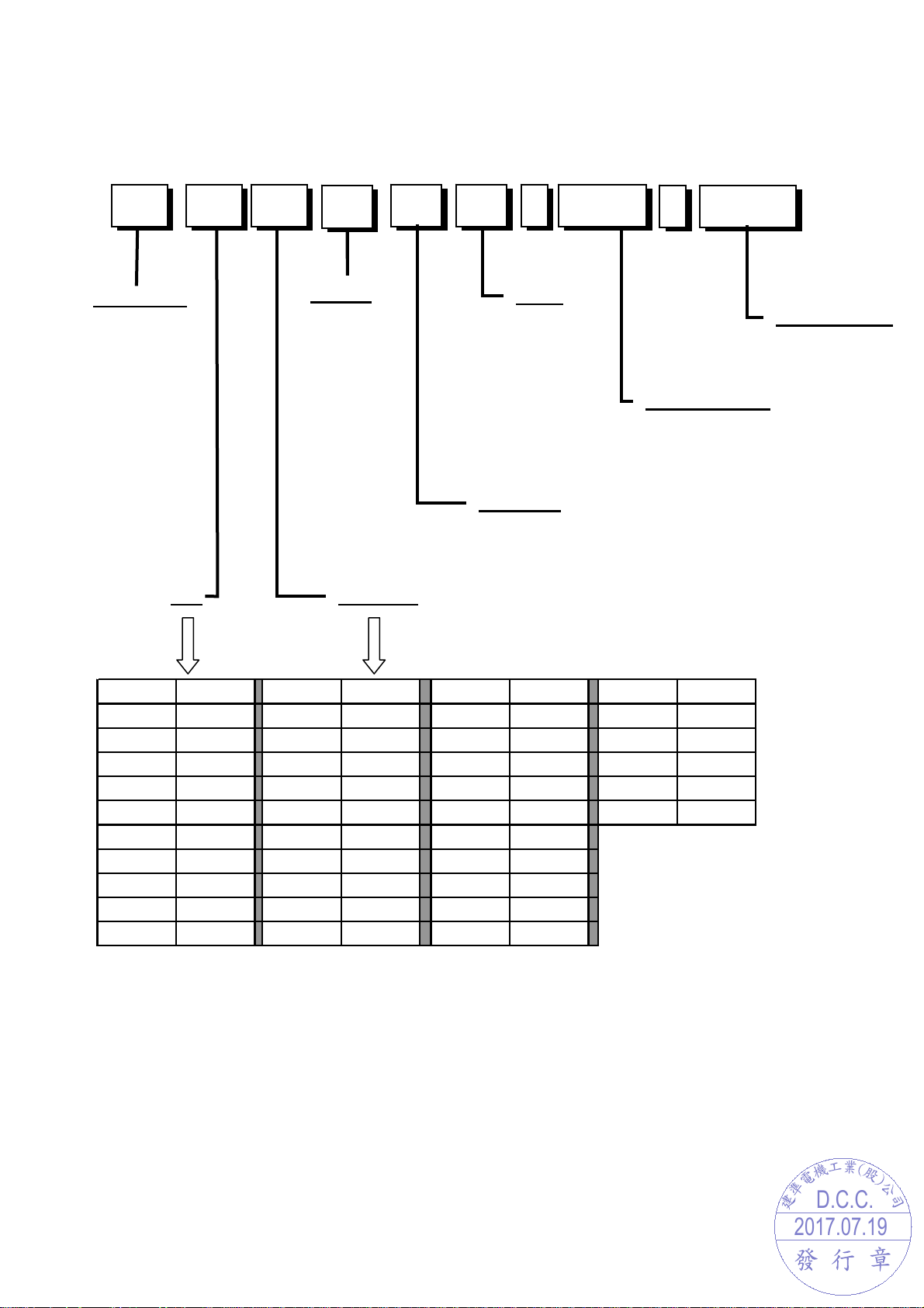
I. MODEL NUMBERING SYSTEM
2017.07.19
D.C.C.
MF
25 80
1
-V 1
1000U
-
G99
Series Code
Voltage
0: 5VDC
1: 12VDC
2: 24VDC
3: 36VDC
4: 48VDC
Speed
X:Super High
1: High
2: Medium
3: Low
4: Extra Low
Customer Code
Size
Thickness
Bearing
V: Vapo
B: 2 Ball
O: 1Ball
S: Sleeve
(mm)
編碼
01~09 01~09 A0~A9 100~109 K0~K9 200~209 V0~V9 300~309
10~19 10~19 B0~B9 110~119 L0~L9 210~219 W0~W9 310~319
20~29 20~29 C0~C9 120~129 M0~M9 220~229 X0~X9 320~329
30~39 30~39 D0~D9 130~139 N0~N9 230~239 Y0~Y9 330~339
40~49 40~49 E0~E9 140~149 P0~P9 240~249 Z0~Z9 340~349
50~59 50~59 F0~F9 150~159 Q0~Q9 250~259
60~69 60~69 G0~G9 160~169 R0~R9 260~269
70~79 70~79 H0~H9 170~179 S0~S9 270~279
80~89 80~89 I0~I9 180~189 T0~T9 280~289
90~99 90~99 J0~J9 190~199 U0~U9 290~299
尺寸
編碼
尺寸
(mm)
編碼
尺寸
(mm)
編碼
尺寸
Function Code
(mm)
建 準 電 機
SUNONWEALTH
Page 2 of 15
Page 3

II. SPECIFICATION
2017.07.19
D.C.C.
1. MECHANICAL CHARACTERISTIC
MOTOR DESIGN
BEARING SYSTEM
DIMENSIONS
MATERIALS OF FRAME
MATERIALS OF FAN BLADE
DIRECTION OF ROTATION
MOUNTING HOLES
WEIGHT
Single phase, 4-poles Brushless DC motor
Precise Vapo bearing system
See Page 6
Thermoplastic PBT of UL 94V-0
Thermoplastic PBT of UL 94V-0
Counter-clockwise viewed from front of fan blade
Diameter 4.3 mm in 8 holes
75 g
2. ELECTRIC CHARACTERISTIC
RATED VOLTAGE
RATED CURRENT
RATED POWER CONSUMPTION
OPERATING VOLTAGE RANGE
STARTING VOLTAGE
OPERATING TEMPERATURE RANGE
STORAGE TEMPERATURE RANGE
12 VDC
120 mA / Max. 138 mA
1.44 WATTS / Max. 1.66 WATTS
4.5~13.8 VDC
4.5 VDC (25 deg. C POWER ON/OFF)
-10 to + 70 deg. C
-40 to + 70 deg. C
建 準 電 機
SUNONWEALTH
Page 3 of 15
Page 4

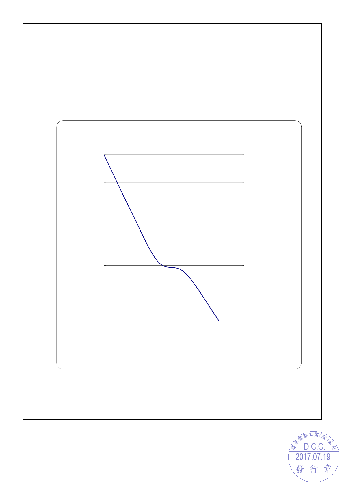
3. PERFORMANCE CHARACTERISTIC
p
2017.07.19
D.C.C.
RATED SPEED 3200 RPM ± 10% at rated voltage
AIR FLOW
STATIC PRESSURE
ACOUSTIC NOISE
AIR FLOW V.S. PRESSURE See Page 5
INSULATION CLASS UL Class A
INSULATION RESISTANCE
PLASTIC HOUSING
DIELECTRIC STRENGTH Applied AC 500 V for one minute or AC 600 V for 2
LIFE EXPECTANCY 70,000 hrs at 40 deg. C, 65% humidity, 90% CL.
PROTECTION
41.0 CFM
0.18 Inch-H2O
33.0 dB(A)
10M ohm at 500 VDC between internal stator and
Lead wire (+)
Seconds between housing and lead wire (+)
Automatic Restart
Note: In a situation where the fan is locked by an external
force while the electricity is on, an increase in coil
temperature will be prevented by tem
electrical power to the motor. The fan will automatically
restart when the locked rotor condition is released.
orarily turning off the
Polarity Protection
4. SAFETY
SAFETY UL CUR TUV CE
NO. E77551 E77551
建 準 電 機
SUNONWEALTH
Page 4 of 15
Page 5
2017.07.19
D.C.C.
MODEL : MF80251V1-1000U-G99
PERFORMANCE CURVES
O)
2
Static Pressure (Inch-H
0 0.28 0.56 0.84 1.12 1.4
0.18
0.15
0.12
0.09
0.06
0.03
m3/min
4.5
3.75
3
2.25
1.5
0.75
O
2
mm-H
0
0 1020304050
Air Flow-CFM
0
建 準 電 機
SUNONWEALTH
Page 5 of 15
Page 6

DIMENSIONS
2017.07.19
D.C.C.
(Pan head)
Machine screw
Self-tapping screw
Note: SUNON recommends the screw and torque as above. Please contact SUNON, if any
new requirement is requested.
Torque
Size Standard
3~4 Kgf-cm
5~6 Kgf-cm ∮5.0
M4.0 JIS B1111-1974
Screw Spec Screw Type
JIS B1122 Type 2
UNIT:mm
建 準 電 機
SUNONWEALTH
Page 6 of 15
Page 7

2017.07.19
D.C.C.
LABEL
建 準 電 機
SUNONWEALTH
Page 7 of 15
Page 8

2017.07.19
D.C.C.
FAN 3rd WIRE SIGNAL
● F Type (Frequency Generator)
F A N
(+)
FG O utput
U SER SYSTEM
Vcc
If
V+
Ra
(-)
+
*Ra ≧ V
FA N
Operation
Current
FG Output
Voltage
★
Electrical Characteristics :( at Ta = 25
FG Supply Voltage(V+) Voltage
FG Output Current (If) mA
/ If (max)
t1t2
OFF RUN LOCKED
℃,
Vcc =Rated Volt.)
Parameter
FG Output (VL) Voltage
FG Output (VH) Voltage
Ratio(=t1/t2)
min. typ. max.
-- -- 13.8
-- -- 5
-- -- 0.5
-- V+ --
-- 6.5 --
Ratings
Unit
V H
V L
VH
FG Output
Voltage
T1 T2 T3 T4
T = 1 Rotation
T= T1+T2+T3+T4=1 Rotation
60
T=
rpm
VL
建 準 電 機
SUNONWEALTH
Page 8 of 15
Page 9

III. OTHER SPECIFIED TESTING
2017.07.19
D.C.C.
The following is a general description of certain tests that are performed on
representative SUNON fans. Nothing in this document is intended to suggest that these
tests are performed on every model of SUNON fan. Moreover, the descriptions that
follow each test are meant only to provide a general explanation of each test. If you
would like a more detailed explanation as to any test identified in this Section, SUNON
can provide such an explanation upon request.
1. DROP PROOF TEST
Fans are packaged in a standard size shipping box and are dropped to the ground from
certain heights and angles depending on the weight of the particular box.
2. HUMIDITY PROOF TEST
The fan is operated for 96 continuous hours in an environment with humidity of 90% to
95% RH at 60°C 2°C.
3. VIBRATION PROOF TEST
Vibration with an amplitude 2mm and a frequency of 5-55-5hz is applied in all 3
directions (X,Y,Z), in cycles of 1 hour each, for a total vibration time of 3hours.
4. THERMAL CYCLING TEST
The fan is operated in a testing chamber for 50 cycles. In each cycle, the temperature is
gradually increased from -10°C to 70°C for 90 minutes, and subsequently operated at
70°C for 120 minutes. The temperature is then gradually decreased from 70°C to -10°C
for 90 minutes, and subsequently operated at -10°C for 120 minutes.
5. SHOCK PROOF TEST
100G of force is applied in the 3 directions (X,Y, and Z) for 2 milliseconds each.
6. LIFE EXPECTANCY
The “Life Expectancy” of SUNON fans is determined in SUNON’s reliability test
laboratory by using temperature chambers. The “Life Expectancy” of this fan has not
been evaluated for use in combination with any end application. Therefore, the Life
Expectancy Test Reports (L10 and MTTF Report) that relate to this fan are only for
reference.
建 準 電 機
SUNONWEALTH
Page 9 of 15
Page 10

IV. CHARACTERISTIC DEFINITION
2017.07.19
D.C.C.
The following is a general description of certain tests that are performed on
representative SUNON fans in order to determine the specifications of the fan. Nothing
in this document is intended to suggest that these tests are performed on every model of
SUNON fan. Moreover, the descriptions that follow each test are meant only to provide
a general explanation of each test. If you would like a more detailed explanation as to
any test identified in this Section, SUNON can provide such an explanation upon
request.
1. ACOUSTICAL NOISE
Measured in a semi-anechoic chamber with background noise level below 15dB(A).
1 METER FROM MICROPHONE TO FAN INTAKE
The fan is running in free air under shaft horizontal condition with the microphone at
distance of one meter from the fan intake.
2. INPUT POWER
Measured after continuous 10 minute operation at rated voltage in clean air
( STATIC PRESSURE=0), and at ambient temperature of 25 degrees C under shaft
horizontal condition.
3. RATED CURRENT
Measured after continuous 10 minute operation at rated voltage in clean air
( STATIC PRESSURE=0), and at ambient temperature of 25 degrees C under shaft
horizontal condition.
建 準 電 機
SUNONWEALTH
Page 10 of 15
Page 11

4. RATED SPEED
2017.07.19
D.C.C.
Measured after continuous 10 minute operation at rated voltage in clean air
( STATIC PRESSURE=0), and at ambient temperature of 25 degrees C under shaft
horizontal condition.
5. STARTING VOLTAGE
Measured the voltage which enables to start the fan in the clean air (static pressure = 0 )
by switching on at the voltage under shaft horizontal condition. It is not at continuously
increasing voltage adjustment.
6. LOCKED ROTOR CURRENT
Measured immediately after the fan blade is locked.
7. AIR FLOW AND STATIC PRESSURE
The performance specification of air flow and static pressure shown in this specification for
approval is measured using the exhaust method. A double chamber is used in accordance
with AMCA 210 standard or DIN 24163 specification . The values are recorded when the
fan speed has stabilized at rated voltage.
8. INSULATION RESISTANCE
1. PLASTIC HOUSING:
(1) Measured between internal stator and lead wire(+).
(2) Measured between housing and lead wire(+).
2. ALUMINIUM HOUSING:
Measured between internal stator and lead wire(+).
9. DIELECTRIC STRENGTH
Measure between housing and lead wire(+).
建 準 電 機
SUNONWEALTH
Page 11 of 15
Page 12

V. NOTE
2017.07.19
D.C.C.
Ⅰ
.SAFETY
1. DO NOT use or operate this fan in excess of the limitations set forth in this
specification. SUNON is not responsible for the non-performance of this fan and/or
any damages resulting from its use, if it is not used or operated in accordance with
the specifications.
2. SUNON recommends adding a protection circuit to the product or application in
which this fan is installed, such as a thermo-fuse, or current-fuse or thermo-protector.
The failure to use such a device may result in smoke, fire, electric shock by
insulation degradation in cases of motor lead short circuit, overload, or over voltage,
and/or other failure.
3. SUNON recommends installing a protection device to the product or application in
which this fan is installed if there is a possibility of reverse-connection between
VDC (+) and GND (-). The failure to install such a device may result in smoke, fire,
and/or destruction, although these conditions may not manifest immediately.
4. This fan must be installed and used in compliance with all applicable safety
standards and regulations.
5. Use proper care when handling and/or installing this fan. Improper handling or
installation of this fan may cause damage that could result in unsafe conditions.
6. Use proper care during installation and/or wiring. Failure to use proper care may
cause damage to certain components of the fan including, but not limited to, the coil
and lead wires, which could result in smoke and/or fire.
7. DO NOT use power or ground PWM to control the fan speed. If the fan speed needs
to be adjusted, please contact SUNON to customize the product design for your
application.
8. For critical or extreme environments, including non stop operation, please contact
SUNON and we will gladly provide assistance with your product selection to ensure
an appropriate cooling product for your application.
建 準 電 機
SUNONWEALTH
Page 12 of 15
Page 13

II. SPECIFICATION MODIFICATION
2017.07.19
D.C.C.
1. SUNON offers engineering assistance on fan installation and cooling system design.
2. All changes, modifications and/or revisions to the specifications, if any, are
incorporated in the attached specifications.
3. No changes, modifications and/or revisions to these specifications are effective
absent agreement, by both SUNON and the customer, in writing.
4. This fan will be shipped in accordance with the attached specification unless
SUNON and the customer have agreed otherwise, in writing, as specified in
Paragraph 3, above.
III. OTHER
1. When building your device, please examine thoroughly any variation of EMC,
temperature rise, life data, quality, etc. of this product by shock/drop/vibration
testing, etc. If there are any problems or accidents in connection with this product, it
should be mutually discussed and examined.
2. Use proper care when handling this fan. Components such as fan holders or bearings
may be damaged, if touched with fingers or other objects. Additionally, static
electricity (ESD) may damage the internal circuits of the fan.
3. DO NOT operate this fan in proximity to hazardous materials such as
cyanogens, formalin, phenol, or corrosive gas environments including, but not
limited to, H2S, SO2, NO2, or Cl2.
4. SUNON recommends that you protect this fan from exposure to outside elements
such as dust, condensation, humidity or insects. Exposure of this fan to outside
organic silicon,
elements such as dust, condensation, humidity or insects may affect its performance
and may cause safety hazards. SUNON does not warrant against damage to the
product caused by outside elements.
5. This fan must be installed properly and securely. Improper mounting may cause
harsh resonance, vibration, and noise.
建 準 電 機
SUNONWEALTH
Page 13 of 15
Page 14
6. Fan guards may prevent injury during handling or installation of the fan and are
2017.07.19
D.C.C.
available for sale with this fan.
7. Unless otherwise noted, all testing of this fan is conducted at 25°C ambient
temperature and sixty-five percent (65%) relative humidity.
8. DO NOT store this fan in an environment with high humidity. This fan must be
stored in accordance with the attached specifications regarding storage temperature.
If this fan is stored for more than 6 months, SUNON recommends functional testing
before using.
9. SUNON reserves the right to use components from multiple sources at its discretion.
The use of components from other sources will not affect the specifications as
described herein.
10. The “Life Expectancy” of this fan has not been evaluated for use in combination
with any end application. Therefore, the Life Expectancy Test Reports (L10 and
MTTF Report) that relate to this fan are only for reference.
VI. WARRANTY
This fan is warranted against all defects which are proved to be fault in our
workmanship and material for one year from the date of our delivery. The sole
responsibility under the warranty shall be limited to the repair of the fan or the
replacement thereof, at SUNON’s sole discretion. SUNON will not be responsible for
the failures of its fans due to improper handing, misuse or the failure to follow
specifications or instructions for use. In the event of warranty claim, the customer shall
immediately notify SUNON for verification. SUNON will not be responsible for any
consequential damage to the customer’s equipment as a result of any fans proven to be
defective.
建 準 電 機
SUNONWEALTH
Page 14 of 15
Page 15
2017.07.19
D.C.C.
Declaration of RoHS
Control declaration of environment-related substances/materials
1. In accordance with the Restriction of Hazardous Substances (RoHS) Directive
2011/65/EU, SUNON product have complied with law and discipline not to employ
the forbidden substances, and restrict the allowable concentration of some limited
substances deliberately in our components.
No Substance Criteria
1 CFCs & HCFCs (ozone depleting substances) Forbidden
2 Chlorinated Organic Solvent Forbidden
Plastic (Frame, Impeller, wire harness, etc.) <100ppm
Solder <1000ppm
3 Lead and its compounds
4 Cadmium and its compounds
5 PBBs and PBDEs Forbidden
6 PCB and PCT Forbidden
7 CP, Short-chain Chlorinated paraffins C10-13, Cl ≥48 wt% Forbidden
8 Mirex Forbidden
9 PCN Forbidden
10 Hexavalent Chromium compounds <100ppm
11 Mercury and its compounds Forbidden
12 Asbestos Forbidden
13 Organic Tin compounds Forbidden
Steel alloy <3500ppm
Aluminium alloy <4000ppm
Copper alloy <4wt%
Solder <20ppm
Parts composed of metals containing zinc
(e.g. brass, zinc for die casting)
Plastic <5ppm
<100ppm
14 Azo compounds Forbidden
15 TBBP-A in external case plastic parts of products (PCB is exempted) <1000ppm
16
17 Hexabromocyclododecane (HBCDD) <1000ppm
18 Di-butyl Phthalate (DBP) <1000ppm
19 Benzyl butyl Phthalate (BBP) <1000ppm
20 Di-ethylhexyl Phthalate (DEHP) <1000ppm
21 Di-isobutyl Phthalate (DIBP) <1000ppm
Nickel in external case parts, which are likely to result in prolonged skin exposure
建 準 電 機
SUNONWEALTH
Page 15 of 15
<1000ppm
 Loading...