

Page 1
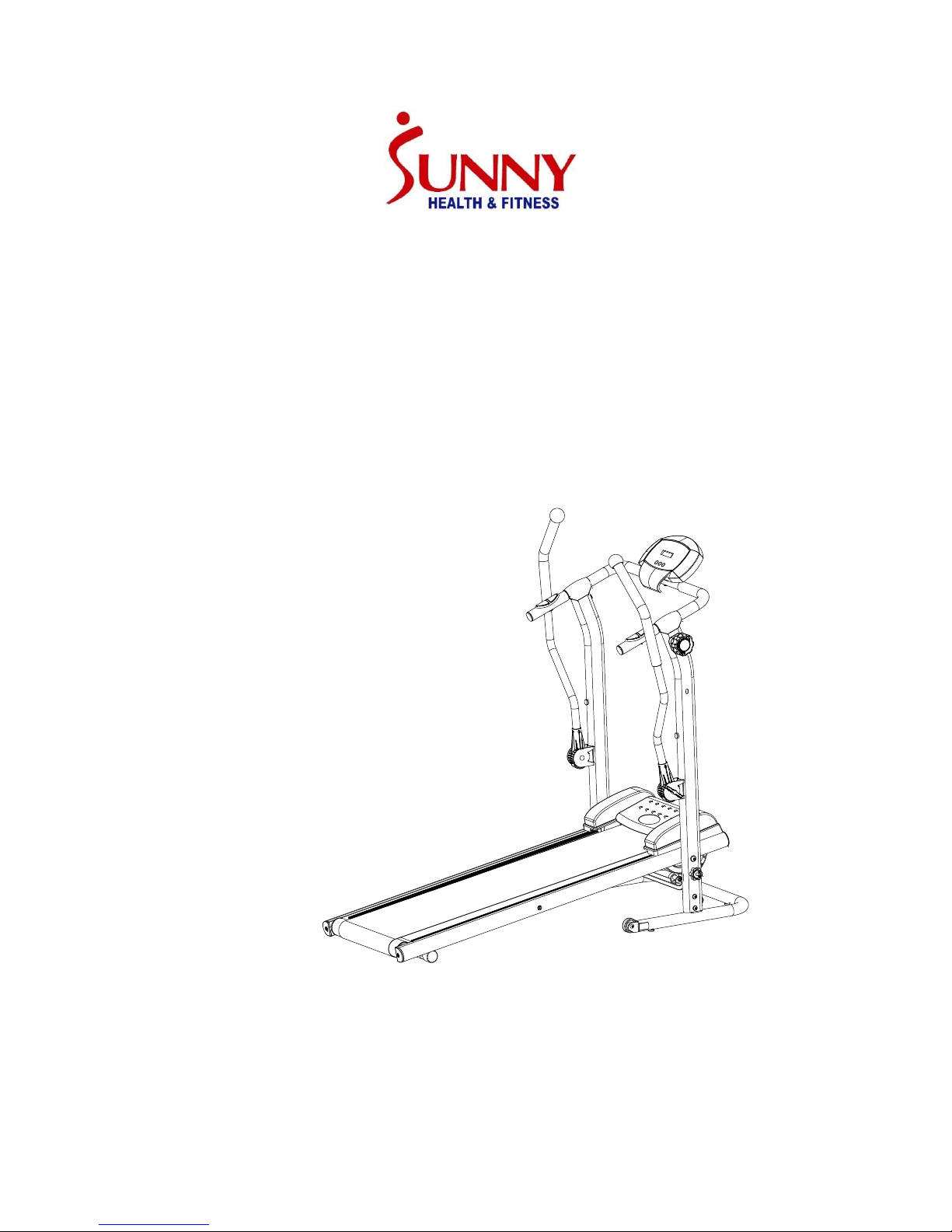
CROSS TRAINING
MAGNETIC TREADMILL
SF-T7615
USER MANUAL
IMPORTANT :
Read all instructions carefully before using this product. Retain this
manual for future reference. For customer service, contact
support@sunnyhealthfitness.com
Page 2

Page 3

1
PRECAUTIONS
WARNING:TO REDUCE THE RISK OF SERIOUS INJURY, READ THE FOLLOWING
IMPORTANT PRECAUTIONS BEFORE USING THE TREADMILL.
1.
Read all instructions in this instruction book before using the treadmill. Use
the treadmill only in the way described in this instruction book.
2.
It is the responsibility of the owner to ensure that all users are adequately
informed of all precautions.
3.
Use the treadmill indoors on a level surface and keep at least 3 feet of free
space all around it.
4.
Check the treadmill regularly for damage, wear or tear. Replace defective
components immediately. If there are any defective components, do not
use the treadmill.
5.
Keep children away from the treadmill at all times.
6.
Wear appropriate clothing and athletic shoes. Do not wear loose clothing
or jewelry when exercising.
7.
If you feel pain or dizziness while exercising, stop immediately.
8.
The treadmill is intended for home use only.
9.
The treadmill is not intended for therapeutic purposes.
10.
Maximum user weight is 220 lbs.
WARNING: BEFORE BEGINNING THIS OR ANY EXERCISE PROGRAM, CONSULT
YOUR DOCTOR. THIS IS ESPECIALLY IMPORTANT FOR PEOPLE WITH
HEALTH
PROBLEMS. READ ALL INSTRUCTIONS BEFORE USING THE
TREADMILL.
Page 4
2
EXPLODED VIEW
9
S
R
Page 5

3
PART LIST
NO.
DESCRIPTION
Q’TY
1 Main frame
1 2 Bottom frame
1
3 Left side hand post
1 4 Right side hand post
1 5 Handle bar
1 6 Base of the magnet
1 7 Front roller
1 8 Front axle
1
9 Rear roller
1
10
Rear axle
1 11
Bolt M6*75L
2 12
Washer OD13*ID6.2
2 13
Bolt M6*75L
2 14
Bolt M5*20L
6 15
Nut
2 16
Bolt M3*10L
2 17
Sensor wire connector
1 18
Bolt M8*45L
1 19
Bolt M5*20L
1 20
Bolt M6
1 21
Bolt M8*40L
2 22
Sensor wire connector
1
23
Nut M8
2
24
Sensor
1 25
Hand pulse sensor
2
26
Hand pulse sensor connector
1
27
Bolt M4*20L
2 28
Spring
1 29
Handle bar grip
2 30
Handle bar grip (with hole)
2 31
Clasp
1
32
Rear end cap
2 33
Plastic washer
4 34
Cover of handle
2 35
Side rail
2
36
End cap
2
37
Front end cap
2
Page 6

4
PART LIST
NO.
DESCRIPTION
Q’TY
38
Plastic cover
1 39
Plastic wheel
2
40
Base frame cushion
6
41
Computer
1 42
Plug
4
43
Plastic end cap
2
44
Magnet
7
45
Running board
1
46
Running belt
1
47
Tension knob
1 48R Handle bar (R)
1
48L
Handle bar (L)
1
A
Bolt M8*15L
6 B Bolt M6*10L
2
C Bolt M8*45L
2
D Bolt M5*12L
2
E Bolt M8*50L
2
F Washer OD16*ID8.3
6 G Arc washer OD16*ID10.3
4
H Washer OD22*ID8.3
2
I
Washer OD12*ID5.2
2 J Knob M8*60L
1
K Washer OD13*ID6.1
2
L Wrench S5
1 M Wrench S6
1
N
Bolt M8X65
2
O
Sleeve
2
P
Knob
2
Q
Plastic washer
2
R
Baffle plate
1 S Tension permanent seat
1 T Steel wire cap
1
U
Tension nut
1 V Tension bolt
1
W
Tension nut-2
1 X Tension sleeve
1
Page 7
5
ASSEMBLY
NOTICE
Read this manual before assmbly
Check the spare parts first.
Check the hardware.
Ensure that you have the right tool.
Prepare an area to assemble.
Follow the instructions accordingly.
Never force the joints
Keep this manual with you
NOTICE
Read this manual before assembly.
Check that you have all the parts for assembly.
Check the hardware.
Ensure that you have the right tool.
Prepare an area to assemble.
Follow the instructions accordingly.
Never force the joints.
Keep this manual for future reference.
Page 8

6
ASSEMBLY
NO.
DESCRIPTION
Q’TY
NO.
DESCRIPTION
Q’TY
1
Main Frame
1
38
Plastic Cover
1
2
Bottom Frame
1
41
Computer
1 3 Left Side Hand Post
1
34
Cover of Handle
2
4
Right Side Hand Post
1
48R
Handle bar (R)
1
5
Handle Bar
1
48L
Handle bar (L)
1
Page 9

7
ASSEMBLY PARTS LIST
5
5
Page 10

8
ASSEMBLY
STEP 1
Attach Right and Left Side Hand Posts (3 & 4) to the Bottom Frame (2),
then fasten them with Bolts, Washers and Arc Washers (A, F & G).
REFER TO THE PARTS LIST AND THE TOOL LIST TO ASSEMBLE THE
PRODUCT.
Page 11

9
STEP 2
Before you assemble the
tension cable, make sure
that it is at level 8.
To assemble the magnetic tension adjustment mechanism:
1. Insert tension wire into the gap in R, then lower T into the hole in R.
Then insert tension wire into the gap in S, keeping U between R and S.
W
X
R
T
X
T
U
V
L
O
R
T
N
O
C
N
O
I
S
N
E
T
HIGHLOW
8
7
6
5
4
3
2
1
+-
Page 12

10
2.Pull X downward to bring R close to X, then insert V into S.
3.Turn U clockwise in order to tighten U and V well.
Page 13

11
STEP 3
Cover the flywheels with Plastic
Cover (38), then secure
it with Screws (B) and
Washer (K).
STEP 4
Ensure the holes are aligned.
Stabilize the Right and
Left Side Hand Posts (3 & 4)
and raise the Main Frame (1).
Attach Right and Left Side Hand
Posts (3 & 4) to the Main
Frame (1) and secure them with
Bolts (E) and Big Washers (H).
Do not tighten all the way yet.
Page 14

12
STEP 5
Connect the Sensor Wire
Connectors (24 & 22).
STEP 6
Place the Handrail (5) onto the Right
and Left Side Hand Posts (3&4) and
secure them with Bolts (C) and Arc
Washers (G).
Connect the Sensor Wire Connectors
(17 & 22).
Put the Cover of Handle (34) on the
handle bar.
Then tighten Bolts (E).
E
Page 15

13
STEP 7
Unscrew Bolt (D) and Washer (I) from
plastic base of the Computer (41).
Attach the Computer (41)
to the Handrail (5), Insert the
Sensor Wire Connector (17)
and the Hand Pulse Connector (26)
into the Computer (41), and then
secure with Bolt (D) and Washer (I).
STEP 8
Attach the right and left side
Handle Bar (48R & 48L) to
The Handle Post (4), secure
them with Sleeve (O), plastic
Washer (F) and Knob (P). Screw
the Knob (J) into the bottom holes
of the Right Side Hand Posts (4)
the Main Frame (1).
Now your treadmill is
assembled.
Check all the parts are fastened or tightened before using.
13
Page 16

14
FOLDING
Loosen Knob (J) completely
before folding.
Lift Main Frame to the
upright position.
Put Knob (J)
back in and tighten.
ADJUSTING THE BELT
If the belt is not centered correctly, the machine will be noisy.
If the belt is too tight, too loose or not centered, use the 5mm wrench to adjust
it.
1.
If the belt drifts to the right, turn the right screw 1 or 2 turns.
2.
If the belt drifts to the left, turn the left screw 1 or 2 turns.
3.
If the belt is too tight, turn the left and right screws counterclockwise.
4.
If the belt is too loose, turn the left and right screws clockwise.
Page 17

15
ADJUSTING THE TENSION
The user can set the desired tension according to the picture below:
To decrease the tension, turn Bolt (13) clockwise.
To increase the tension, turn Bolt (13) counterclockwise.
After adjusting the Bolt (13), check if the tension wire is too loose. If necessary,
adjust the Bolts (U or W) on tension wire.
Clockwise - decrease tension
Counterclockwise - increase
tension
Page 18

16
The cross training magnetic treadmill has moving handlebars that let you
exercise your arms and upper body. Use the moving handlebars as shown in
the picture below. You can exercise with just the handlebars or use them while
walking on the treadmill.
How to set up the tension of the handlebars:
Use Knob (P) to adjust the
tension of the moving handlebars.
Turn clockwise to increase the
tension. Turn counterclockwise to
decrease the tension.
Page 19

17
MAINTENANCE
Treadmill Lubrication
To reduce the friction of the walking belt and minimize wear, apply lubricant
directly onto the Treadboard and underside of the Belt.
Lift one side of the Belt and feel the top surface of the Treadboard. If the
surface is wet to the touch, no lubrication is required. If the surface is dry to the
touch, lift one edge of the Belt and spray or apply lubricant to the Treadboard.
Make sure to walk on your treadmill at a slow speed for the first 3-4 minutes of
use after applying lubricant. This helps to distribute the lubricant.
NOTE: Do not over lubricate the Treadboard. Wipe off any excess lubricant.
Lubricant may be applied whenever friction occurs, but is usually required
every 50 hours of use. This is only a guideline. Depending on your usage, you
may need to lubricate more often.
Page 20

18
How to move the treadmill:
To transport, hold the
treadmill at "25" and tilt
until the wheel "39" are
able to move on the
ground.
Before attempting to move the
treadmill, please make sure
that it has been properly
folded. The Knob (J) must be
tightened
Start by placing two hands at
position "25" to support the
treadmill. Next, please place
one foot at position "39" to
hold the bottom end of the
treadmill steady. With your foot
at "39", slowly tilt the top of the
treadmill downward towards
the ground. Once the Main
Frame reaches a low enough
point, the wheels of treadmill
will touch the ground.
Page 21

19
OPERATING INSTRUCTIONS
TIME………………………………………….……….00:00~99:59 MIN
SPEED………………………………………….............0.0~99.99 MI/H
DISTANCE……………………………………….…........0.00~999.9 MI
CALORIE………………………………………………..0.0~999.9 KCAL
PULSE……………………………………….....................40~220 BPM
The display will turn on when you start walking on the treadmill or when you
press a key.
After 4-5 minutes of inactivity, the display will shut off automatically. When the
treadmill is not moving, computer will display “STOP” on the side.
MODE: Press this button to select and set to a function. Hold on for 2 seconds
to reset the monitor. The data for all functions will be cleared.
SET: Under “STOP” condition, press this button to set the value of TIME,
DISTANCE, CALORIES or PULSE. You can hold the button for seconds to
increase the data.
RESET: Press this button to reset each function: Time, Distance, Calorie, Pulse.
Hold on for 2 seconds to reset the monitor. The data for all functions will be
cleared. (When you replace the batteries, all the values will reset to ZERO
automatically.)
HOW TO SELECT A FUNCTION:
Press MODE to SCAN. To set a function, press MODE key when the pointer is
on the function you want and the function starts blinking.
FUNCTIONS:
1. TIME: Press the MODE key until pointer is set to TIME. The total working time
will be shown.
2. SPEED: Press the MODE key until pointer is set to SPEED. The current
speed will be shown.
3. DISTANCE: Press the MODE key until pointer is set to DISTANCE. The
distance of each workout will be displayed.
4. CALORIE: Press the MODE key until pointer is set to CALORIE. The calories
burned will be displayed.
5. PULSE: Press the MODE key until the pointer advance to PULSE function
and hold the pulse sensor for about 3 seconds to measure pulse.
Countdown function:Under “STOP” condition, press “SET” button to set
Time, Distance or Calorie to countdown. Once the data goes down to zero, the
computer will beep. That means countdown function ends, and the data starts
counting from “1”. You can set the Countdown function only when the treadmill
is stopped.
SCAN: Displays each function for 4 seconds in the following sequence:
TIME—SPEED—DISTANCE—CALORIE—PULSE
NOTE:
If the LCD display is not functioning properly, change the batteries. When you
change batteries, change both of them. The monitor uses 1.5V “AA” batteries.
Page 22

 Loading...