

Sunny SF-T1408M User Manual
MANUAL WALKING TREADMILL
SF-T1408M
USER MANUAL
IMPORTANT: Please read this manual carefully before using the product. Retain
owner’s manual for future reference. For Customer Service, please contact:
support@sunnyhealthfitness.com

IMPORTANT SAFETY INFORMATION
We thank you for choosing our product. To ensure your safety and health, please use this
equipment correctly. It is important to read this entire manual before assembling and using the
equipment. Safe and effective use can only be assured if the equipment is assembled,
maintained, and used properly. It is your responsibility to ensure that all users of the
equipment are informed of all warnings and precautions.
1. Before starting any exercise program you should consult your physician to determine if
you have any medical or physical conditions that could put your health and safety at
risk or prevent you from using the equipment properly. Your physician’s advice is
essential if you are taking any medication that may affect your heart rate, blood
pressure, or cholesterol level.
2. Be aware of your body’s signals. Incorrect or excessive exercise can damage your
health. Stop exercising if you experience any of the following symptoms: pain,
tightness in your chest, irregular heartbeat, shortness of breath, lightheadedness,
dizziness, or feelings of nausea. If you do experience any of these conditions, you
should consult your physician before continuing with your exercise program.
3. Keep children and pets away from the equipment. The equipment is designed for adult
use only.
4. Use the equipment on a solid, flat level surface with a protective cover for your floor or
carpet. To ensure safety, the equipment should have at least 2 feet of free space all
around it.
5. Ensure that all nuts and bolts are securely tightened before using the equipment. The
safety of the equipment can only be maintained if it is regularly examined for damage
and/or wear and tear.
6. It is recommended that you lubricate all moving parts on a monthly basis.
7. Always use the equipment as indicated. If you find any defective components while
assembling or checking the equipment, or if you hear any unusual noises coming from
the equipment during exercise, stop using the equipment immediately and don’t use
the equipment until the problem has been rectified.
8. Wear suitable clothing while using the equipment. Avoid wearing loose clothing that
may become entangled in the equipment.
9. Do not place fingers or objects into the moving parts of the equipment.
10. The maximum weight capacity of this unit is 250 pounds.
11. This equipment is not suitable for therapeutic use.
12. Move with caution when lifting and moving the equipment. Always use proper lifting
technique and seek assistance if necessary.
13. This equipment is designed for indoor use only! It is not intended for commercial use!
1

EXPLODED DRAWING
2

No.
Description
Qty
No.
Description
Qty
1
Base frame
1
30
Wire Cap 28*12
1 2 Left upright support
1
31
Wire cap D12.5
1
3
Right upright support
1
32
Rear roller
1
4A
Console bracket
1
33
Metal bushing
2
4B
Handlebar
1
34
Wrench with screw driver
1 5 Main frame
1
35
Allen wrench S5
1
6
Adjustable rear stabilizer
1
36
Base pad
4
7
Allen bolt M8*40
2
37
Cap for rear stabilizer
2
8
Allen bolt M8*20
2
38
Transport wheel
2
9
Allen boltM8*30
2
39
Side rail
2
10
Allen bolt M10*60
2
40R
Right end cap
1
11
Carriage bolt M8*50
4
40L
Left end cap
1
12
Adjustable bolt M6*60
2
41
Flywheel cover
1
13
Philips head screw M6*35
6
42
Running deck
1
14
Philips head screw M6*25
2
43
Running belt
1
15
Self tapping screw ST4.2*12
12
44
ABS block
6
16
Self tapping screw ST3.0*10
2
45
Rectangular end cap
2
17
Self tapping screw ST4.2*20
2
46
Handlebar cover
2
18
Self tapping screw ST4.2*15
4
47
Display Console
1
19
Flat washer D12
2
48
Hand pulse sensor
2
20
Flat washer D8
6
49
Hand pulse wire 2
2
21
Flat washer D6
8
50A
Lower sensor wire
1
22
Flat washer D12.5
2
50B
Upper sensor wire
1
23
Philips head screw M5*10
4
51
Hand pulse wire 1
2
24
Curved washer D8
2
52
Sensor wire
1
25
Nylon nut M6
8
53
Handlebar foam
2
26
Nylon nut M8
8
54
Handlebar foam
2
27
Pull pin
2
55
Screw M5*12
2
28
Lock knob
1
56
Allen wrench S6
1
29
Front roller
1
57
Anti-slip stickers
2
PARTS LIST
3
ASSEMBLY INSTRUCTIONS
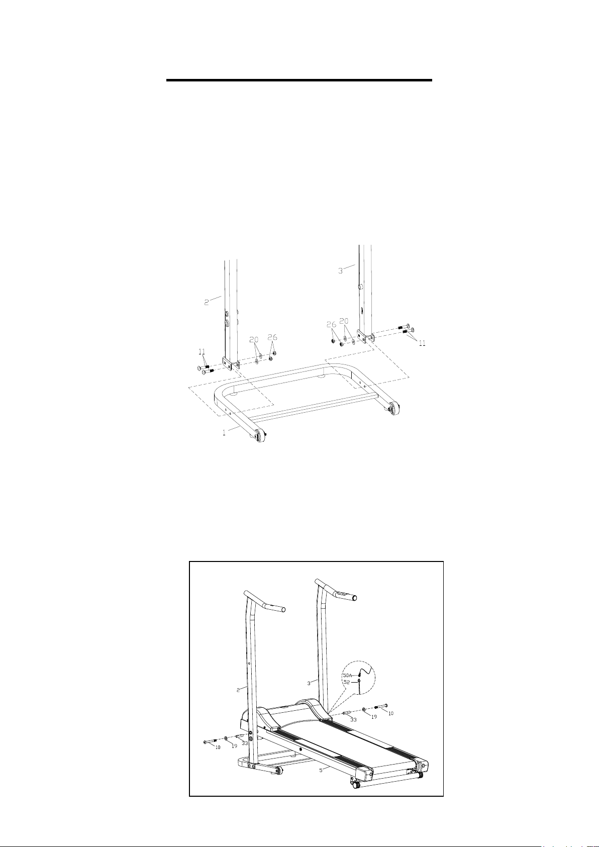
STEP 1:
Attach the Left & Right Upright Supports (No. 2 and No. 3) to the Base Frame (No.
1) using 4 Carriage Bolts (No. 11), 4 Flat Washers (No. 20) and 4 Nylon Nuts (No.
26) and tighten securely.
NOTE: To complete steps that involve assembling heavy components, seek extra
assistance to help hold the components in place during installation. For your safety, do
NOT attempt to complete these steps on your own.
STEP 2:
Attach the Left & Right Upright Supports (No. 2 and No. 3) to the Main Frame (No.
5) using 2 Flat Washers (No. 19), 2 Allen Bolts (No. 10) and 2 Metal Bushings (No.
33), tighten securely.
Connect the Sensor Wire (No. 52) to the Lower Sensor Wire (No. 50A).
4
ASSEMBLY INSTRUCTIONS
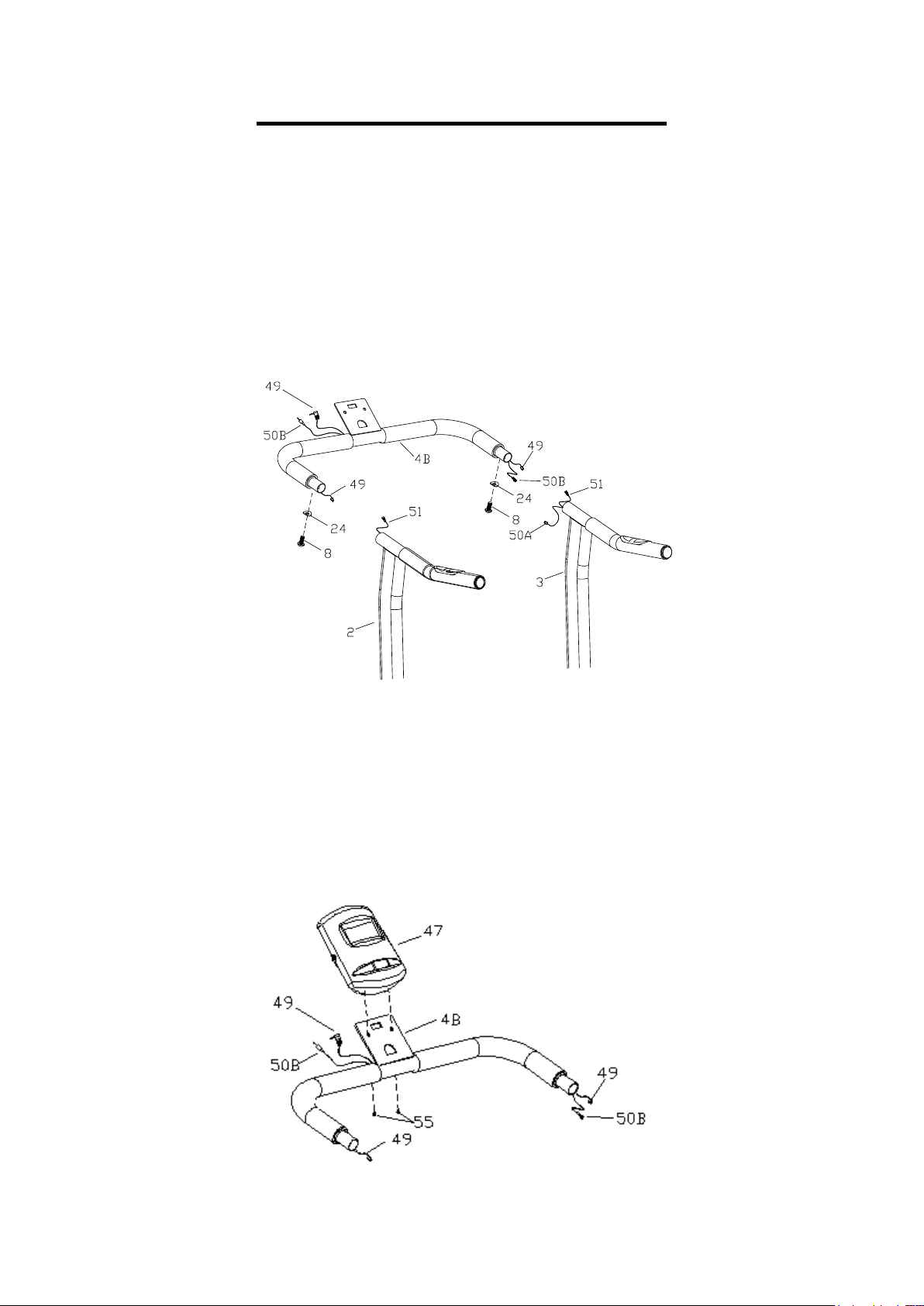
STEP 3:
Connect the other end of Lower Sensor Wire (No. 50A) to the Upper Sensor Wire
(No. 50B), then connect Hand Pulse Wire 2 (No. 49) to Hand Pulse Wire 1 (No. 51)
on both sides.
Insert the Handlebar (No. 4B) into the Left & Right Upright Supports (No. 2 and No.
3). Fix using 2 Allen Bolts (No. 8) and 2 Curved Washers (No. 24) and tighten
securely.
STEP 4:
Loosen and remove Screws (No. 55) from the Console Bracket (No. 47).
Plug the Upper Sensor Wire (No. 50B) and Hand Pulse Wire 2 (No. 49) into the
Display Console (No. 47). Attach the Display Console (No. 47) to the Console
Bracket (No. 4A) using 2 Screws (No.55), tighten securely.
5
 Loading...