

Sunny SF-E3912 User Manual
PRE-PROGRAMMED
ELLIPTICAL TRAINER
SF-E3912
USER MANUAL
IMPORTANT! Please retain owner’s manual for maintenance and adjustment instructions. Your
satisfaction is very important to us, PLEASE DO NOT RETURN UNTIL YOU HAVE CONTACTED
US: support@sunnyhealthfitness.com or 1- 877 - 90SUNNY (877-907-8669).

1
IMPORTANT SAFETY INFORMATION
We thank you for choosing our product. To ensure your safety and health, please use this
equipment correctly. It is important to read this entire manual before assembling and using the
equipment. Safe and effective use can only be achieved if the equipment is assembled,
maintained, and used properly. It is your responsibility to ensure that all users of the equipment
are informed of all warnings and precautions.
1. Before starting any exercise program, you should consult your physician to determine if you
have any medical or physical conditions that could put your health and safety at risk or prevent
you from using the equipment properly. Your physician’s advice is essential if you are taking
medication that affects your heart rate, blood pressure or cholesterol level.
2. Be aware of your body’s signals. Incorrect or excessive exercise can damage your health. Stop
exercising if you experience any of the following symptoms: pain, tightness in your chest,
irregular heartbeat, shortness of breath, lightheadedness, dizziness, or feelings of nausea. If
you do experience any of these conditions, you should consult your physician before
continuing with your exercise program.
3. Keep children and pets away from the equipment. The equipment is designed for adult use
only.
4. Use the equipment on a solid, flat level surface with a protective cover for your floor or carpet.
To ensure safety, the equipment should have at least 2 feet (60CM) of free space all around it.
5. Ensure that all nuts and bolts are securely tightened before using the equipment. The safety of
the equipment can only be maintained if it is regularly examined for damage and/or wear and
tear.
6. Always use the equipment as indicated. If you find any defective components while assembling
or checking the equipment, or if you hear any unusual noises coming from the equipment
during exercise, discontinue use of the equipment immediately and do not use until the
problem has been rectified.
7. Wear suitable clothing while using the equipment. Avoid wearing loose clothing that may
become entangled in the equipment.
8. Do not place fingers or objects into the moving parts of the equipment.
9. The maximum weight capacity of this unit is 330 pounds (150 KG).
10. The equipment is not suitable for therapeutic use.
11. To avoid bodily injury and/or damage to the product or property, proper lifting and moving are
required.
12. Your product is intended for use in cool and dry conditions. You should avoid storage in
extreme cold, hot, or damp areas as this may lead to corrosion and other related problems.
13. This equipment is designed for indoor and home use only; it is not intended for commercial use.
2
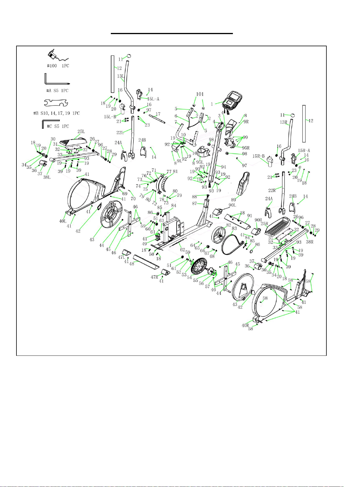
EXPLODED DIAGRAM
3
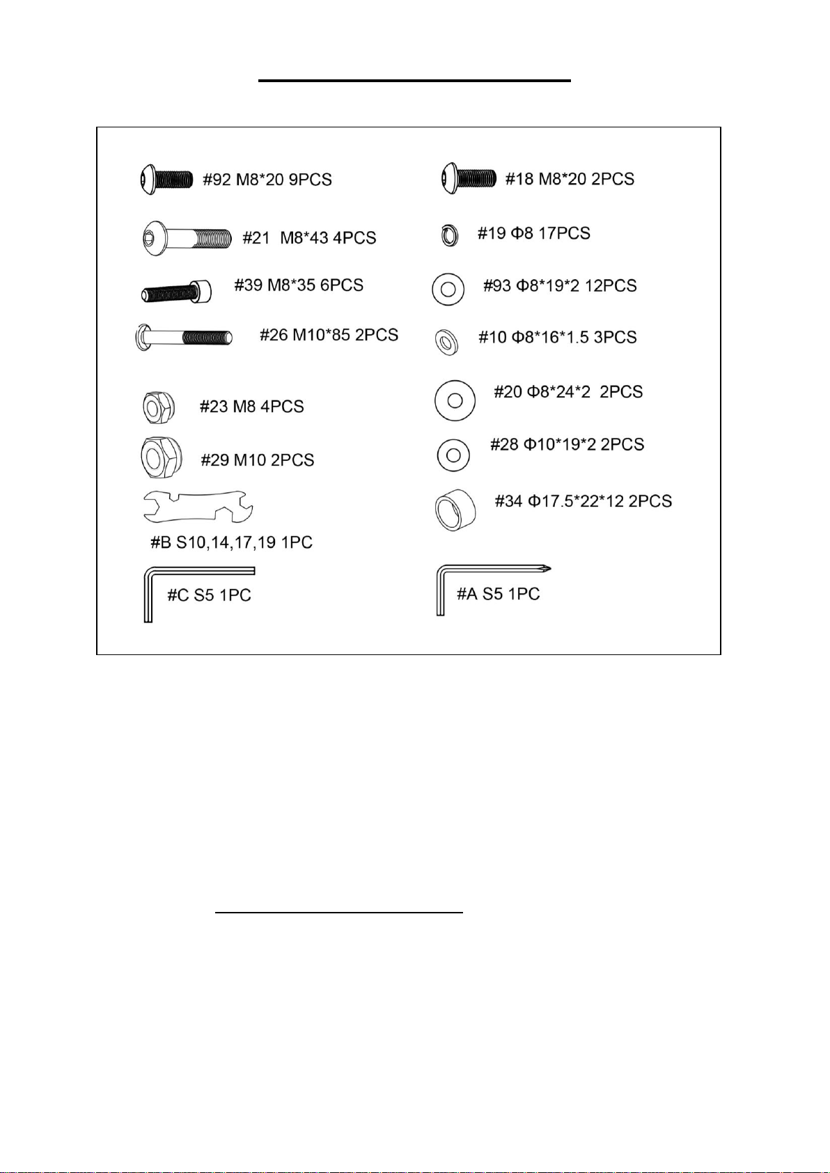
HARDWARE PACKAGE
Ordering Replacement Parts (U.S. and Canadian Customers only)
Please provide the following information in order for us to accurately identify the part(s) needed:
✓ The model number (found on cover of manual)
✓ The product name (found on cover of manual)
✓ The part number found on the “EXPLODED DIAGRAM” and “PARTS LIST” (found near the front
of the manual)
Please contact us at support@sunnyhealthfitness.com or 1- 877 - 90SUNNY (877-907-8669).
4
PARTS LIST
No.
Description
Spec.
Qty.
No.
Description
Spec.
Qty.
1
Computer
TZ-4113
1
24A
Lower Swing Plastic
Cover-A
ABS
2
2
Screw
M3*28
4
24B
Lower Swing Plastic
Cover-B
ABS
2
3
Upper Computer Cable
1000mml
1 25L
Left Pedal
1
4
Screw
M5*10
4
25R
Right Pedal
1 5
Hand Grip
2 26
Bolt
M10*85
2
6
Hand Pulse Cable
650MM
1 27
Bushing
14*32 4 7
Handlebar
Φ32*1.5t
1 28
Washer
Φ10*19*2
2
8
Screw
M5*15
3 29
Nylon Nut
M10
2
9L
Left Console Rack
1 30
Bearing
2203-2RS
2
9R
Console Rack-R
1 31
Pedal Fixed Welding
3T 2 10
Washer
Φ8*16*1.5
3
32
Screw
M5*12
10
11
End Cap
2 33
EVA Foam
20*60*1MM
4
12
Foam
Φ32*3t*560mml
2 34
Tube
Φ17.5*22*12
2
13L
Left Upper Swing Bar
Φ32*1.8t*772mml
1 35
C-sharp Clip
Φ40 2 13R
Right Upper Swing Bar
Φ32*1.8t*772mml
1 36
Screw
M5*7.5
2
14
Screw
M4*20
4
37
M Plastic Cover
Φ46
2
15L-
A
Left Upper Central
Shaft Plastic Cover -A
Φ45.5
1 38L
Left Pedal Support Bar
30*60*1.8t*864m
ml
1
15L-
B
Left Upper Central
Shaft Plastic Cover -B
Φ45.5
1 38R
Right Pedal Support
Bar
30*60*1.8t*864m
ml
1
15R-
A
Right Upper Central
Shaft Plastic Cover -A
Φ45.5
1 39
Screw
M8*35
6
15R-
B
Right Upper Central
Shaft Plastic Cover -B
Φ45.5
1 40L
Left Chain Cover
ABS
1
16
Bearing
6203-2RS
4 40R
Right Chain Cover
ABS
1
17
Axis
Φ18.8*315.2mml
1 41
Drill Screw
M5*20
17
18
Bolt
M8*20
8 42
Crank Cover
45-50°
2
19
Spring Washer
Φ8
19 43
Cycle Plate
ABS 2 20
Washer
Φ8*24*2
4 44
Flathead Screw
M10*1.25
2
21
Bolt
M8*43
4 45
Cross Welding
20*40*1.5t*188m
ml
2
22L
Left Lower Swing Bar
Φ32*1.5t*620mml
1 46
Self-tapping Screw
M4.5*15
8
22R
Right Lower Swing Bar
Φ32*1.5t*620mml
1
47L
Left Rear Stabilizer
End Cap
1
23
Nylon Nut
M8
4
47R
Right Rear Stabilizer
End Cap
1

5
No.
Description
Spec.
Qty.
No.
Description
Spec.
Qty.
48
Rear Stabilizer
52.5*95*1.8t*450
mml
1
78
Spin Axis
Φ12*33.2
1
49
Motor
1
79
Allen Bolt
M6*15
2
50
DC Cable
300MM
1 80
Spring Washer
Φ6
2
51
Bearing
6004-2RS
2 81
Magnet
29.5*20*12MM
10
52
Wave Washer
Φ20*25*0.5
1 82
Flywheel
Φ250*34, 6kgs
1
53
Nylon Nut
M6-10MM
4 83
Belt
480J6
1
54
Belt Wheel
Φ305, J6
1 84
Chain Adjust Set
2
55
Round Metal Welding
Φ20*126mml
1
85
Nut
M10*1.25/
15MM*10T
2
56
Spring Washer
Φ6 4
86
Axis Protection Piece
15MM
2
57
Bolt
M6*15
4 87
Main Frame
1
58
Self-tapping Screw
M4.5*25
8
88
Lower Computer Cable
1350mm
1
59
C-sharp Clip
Φ20 2
89
Front Plastic Cover
8501--5
1
60
Washer
Φ20*25*2
1
90L
Left Front Stabilizer
Cap
1
61
Washer
Φ20*25*1
2
90R
Right Front Stabilizer
Cap
1
62
Conduction Wire
620MM
1
91
Front Stabilizer
52.5*95*1.8t*400
mml
1
63
Sensor
300mml
1 92
Bolt
M8*20
9
64
C-sharp Clip
Φ8 1
93
Washer
Φ8*19*2
12
65
Wave Washer
10*15*0.5
1
94
Handlebar Post
55*61*1.5T*950m
m
1
66
Idler Wheel
φ37*20.5L
1 95L
Left Axis Plastic Cover
Φ38
1
67
Idler Wheel Axis
Φ10*42mml
1
95R
Right Axis Plastic
Cover
Φ38
1
68
Nylon Nut
M10 1
96
Tube
Φ14*10*68.2
2
69
Plastic Screw
1
97
Wave Washer
Φ17*25*0.5
2
70
Gill Pin
Φ3.9*36
1 98
Nylon Bushing
Φ19*38-0.15
2
71
Nut
M6 2
99
Self-tapping Screw
M4*20
4
72
Double-thread Screw
Φ6*80/M6*25
1 100
Adapter
9V/1.0A
1
73
Washer
Φ6*14*1.5
3 101
End Cap
2
74
Silica Gel Washer
Φ8*16*1.5
1 A
Allen Wrench
S5
1
75
Nylon Nut
M6 1 B Spanner
S10, 14, 17, 19
1
76
Spring Washer
Φ1*12
1 C
Allen Wrench
S5
1
77
Magnet Fixed Part
Welding
1
6
ASSEMBLY INSTRUCTIONS
We value your experience using Sunny Health and Fitness products. For assistance with parts or
troubleshooting, please contact us at support@sunnyhealthfitness.com or 1-877-90SUNNY (877907-8669).
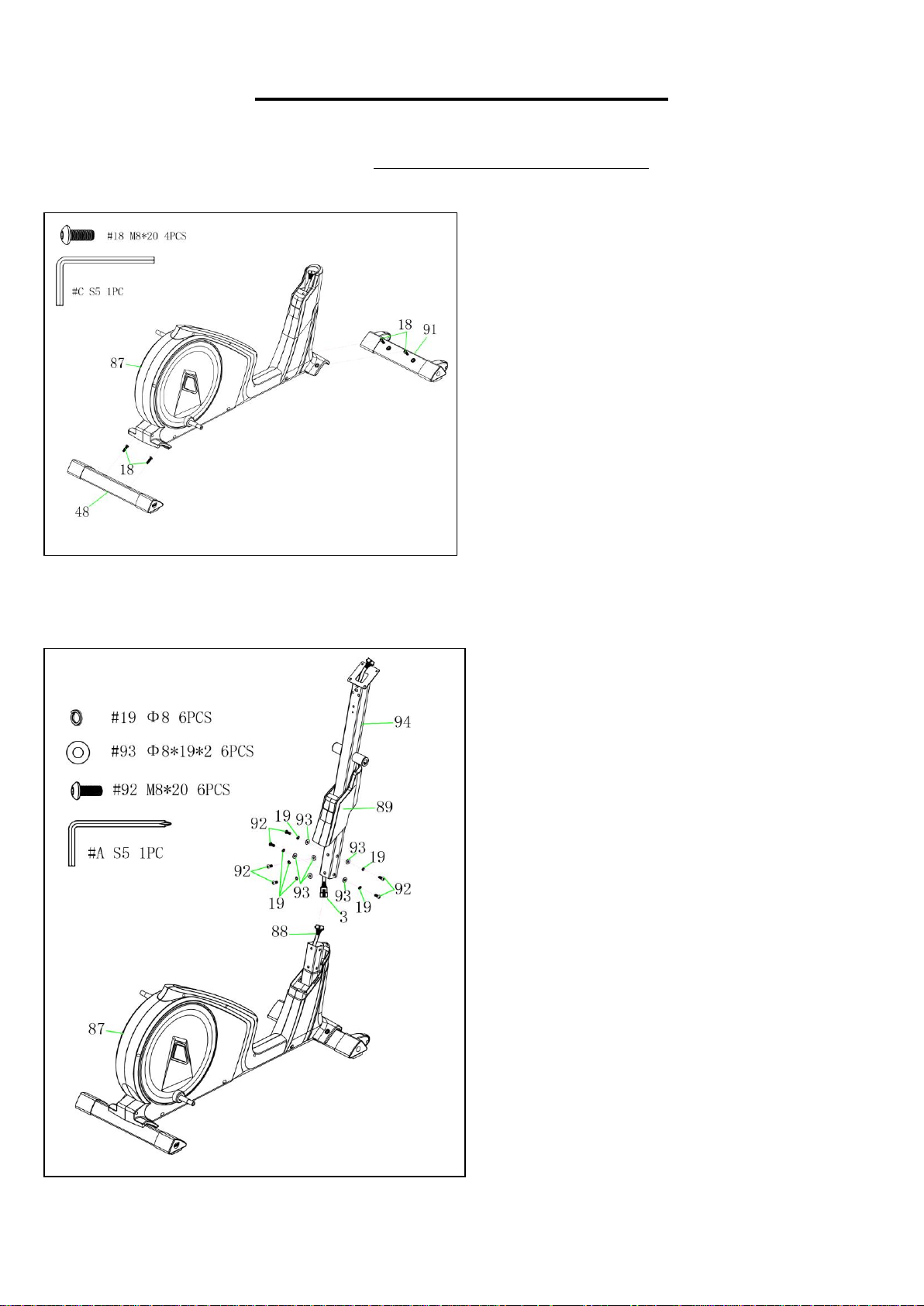
STEP 1:
Remove 2 Bolts (No. 18) from the Front
Stabilizer (No. 91).
Attach the Front Stabilizer (No. 91) to the
Main Frame (No. 87) with 2 Bolts (No. 18)
that were removed. Tighten and secure with
Allen Wrench (No. C).
Remove 2 Bolts (No. 18) from the Rear
Stabilizer (No. 48).
Attach the Rear Stabilizer (No. 48) to the
Main Frame (No. 87) with 2 Bolts (No. 18)
that were removed. Tighten and secure with
Allen Wrench (No. C).
STEP 2:
Put the Front Plastic Cover (No. 89) through
the Handlebar Post (No. 94).
Connect the Lower Computer Cable (No.
88) with the Upper Computer Cable (No. 3).
Attach the Handlebar Post (No. 94) to the
Main Frame (No. 87) with 6 Spring
Washers (No. 19), 6 Washers (No. 93), and
6 Bolts (No. 92). Tighten and secure with
Allen Wrench (No. A). Then, place the Front
Plastic Cover (No. 89) into position.
 Loading...