

Page 1
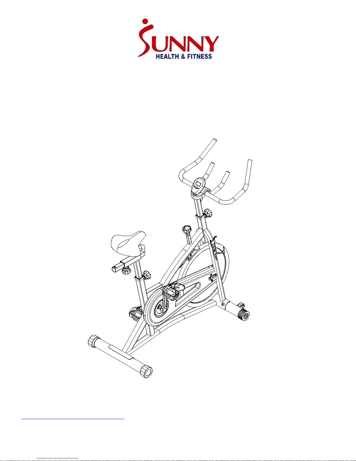
SUNNY INDOOR CYCLING BIKE
SF-B1421
USER MANUAL
IMPORTANT! Please retain owner’s manual for maintenance and adjustment instructions. Your
satisfaction is v ery important to us, PLEASE DO NOT RETURN UNTIL YOU HAVE CONTACTED US:
[email protected] or 1- 877 - 90SUNNY (877-907-8669).
Page 2

IMPORTANT SAFETY INFORMATIO N
We thank you for choosing our pr oduct. To ensur e y our safety and h ealt h, please use thi s equipment
correctly. It is important to read this entire manual before assembling and using the equipment. Safe
and effective use c an onl y be achiev ed if the eq uipment is assembl ed, maint ained an d used properly .
It is your responsibility to ensure that all users of the equipment are informed of all warnings and
precautions.
1. Before starting any exe rc ise prog ram, you sho uld co nsult y our p hys ician t o det ermin e i f y ou hav e
any medical or physical conditions that could put your health and safety at risk, or prevent you
from using the equipment properly. Your physician’s advice is essential if you are taking
medication that affects your heart rate, blood pressure, or cholesterol level.
2. Be aware of your body’s signals. Incorrect or excessive exercise can damage your health. Stop
exercising i f you experience any of the follow ing symptoms: pain, tightness in y our chest, ir regular
heartbeat, shortness of breath, lightheadedness, dizziness, or nauseous feeling. If you do
experience any of th ese conditions , you should c onsult your phy sician before con tinuing wi th your
exercise program.
3. Keep children and pets away from the equipment. The equipment is designed for adult use only.
4. Use the equipment on a solid, flat lev el sur face w it h a protecti ve c over for y our flo or or carpet. T o
ensure safety, the equipment should have at least 2 feet (60 CM) of free space all around it.
5. Ensure that all nuts and bolts are securely tightened before using the equipment. The safety of
the equipment can only be maintained if it is regularly examined for damage and/ or wear and
tear.
6. Always use the equipment as indicated. If you find any defective components while assembling
or checking the equipment, or if you hear any unusual noises coming from the equipment during
exercise, discontinue use of the equipment immediately and do not use until the problem has
been rectified.
7. Wear suitable clothi ng w hile using the equipment. Av oid w earing loose clothi ng that may become
entangled in the equip men t.
8. Do not place fingers or objects into the moving parts of the equipment.
9. The maximum weight capacity of this unit is 265 pounds (120 KG).
10. This equipment is not suitable for therapeutic use.
11. To avoid bodily injury and/ or damage to the product or property, proper lifting and moving are
required.
12. Your product is intended for use in cool , dry conditions . You should avoi d storage in ext reme cold,
hot, or damp areas as this may lead to corrosion and other related problems.
13. This equipment is designed for indoor and home use only; It is not intended for commercial use.
1
Page 3
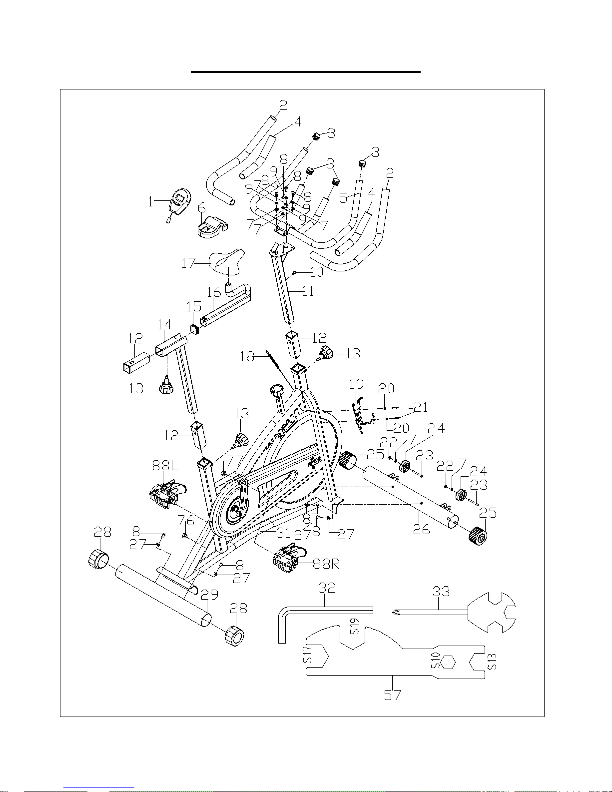
EXPLODED DRAWING 1
2
Page 4
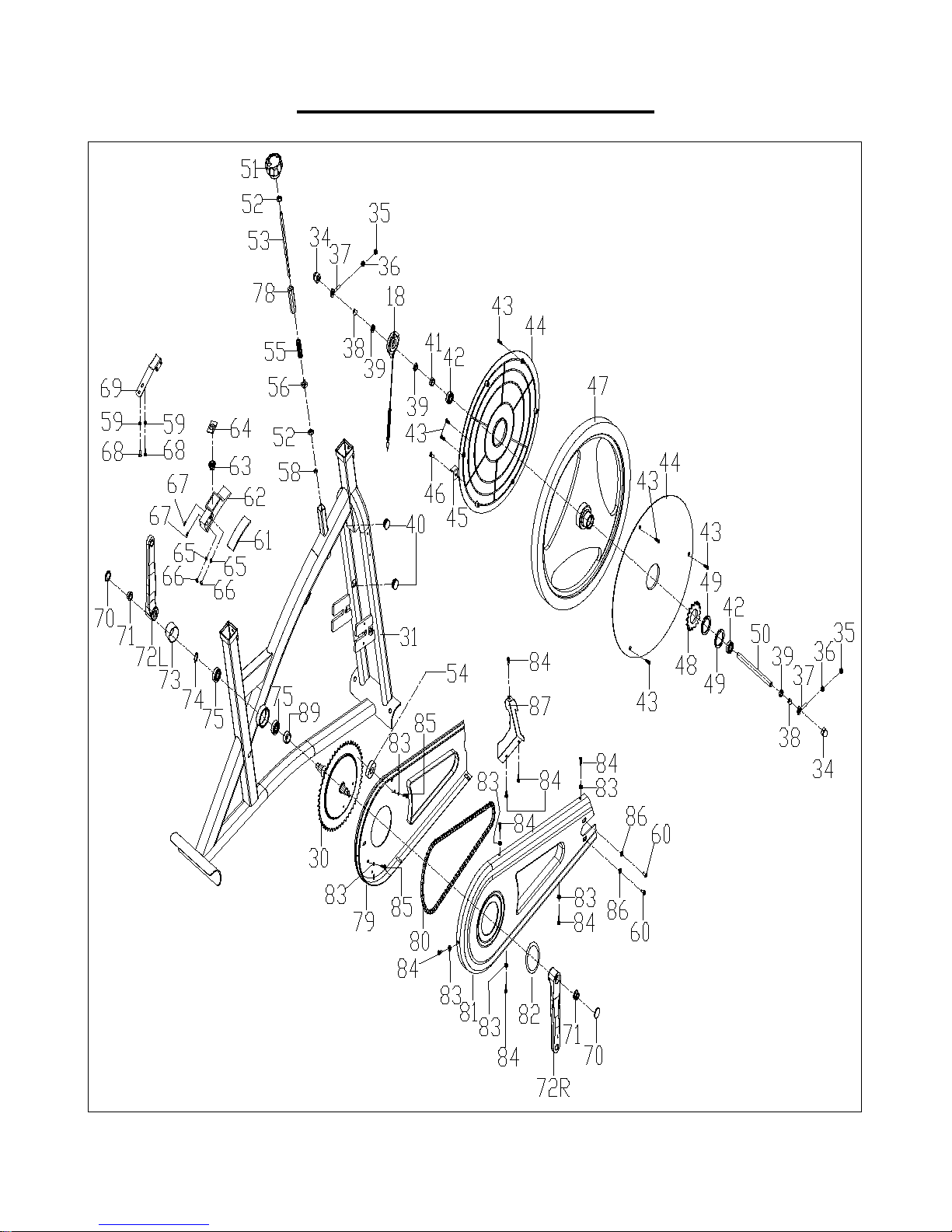
EXPLODED DRAWING 2
3
Page 5
1
Computer
1 35
Nut
M6*H6*S10
2 2 Foam Grip
Φ23*3*480
2
36
Nut
M6*H5*S10
2 3 End Cap
Φ25*16
4
37
Adjusting Screw
M6*50*Φ12*5
2 4 Foam Grip
Φ23*3*190
2
38
Spacer
Φ22*Φ12.5*6
2 5 Handlebar
1 39
Nut
M12*1*H6*S19
3
Handlebar
Cover
7
Washer
d8*16*1.5
6
41
Spacer
Φ18*Φ12.2*4
1 8 Screw
M8*16*S6
8
42
Bearing
6001-2RS
2 9 Spring Washer
d8 4 43
Screw
ST4.8*13*Φ8
6
10
Screw
M5*10*S4
1
44
Flywheel Cover
2 11
Handlebar Post
1 45
Sensor Stopper
t2*20
1
F38*38*F30*30*
L120
Adjustment.
Knob
M16*1.5*18*Φ5
8
14
Seat Post
1 48
Small Chain Wheel
1 15
End Cap
F30*30*16
1
49
Nut
M35*1*44*3.5
2
16
Seat Slider
1 50
Inertia Axle
Φ12*150*M12*1.0
1
17
Seat 1
51
Tension Knob
M10*58*48
1
18
Inductor
1 52
Nut
M10*H5.5*S17
2
Water Bottle
Holder
Φ10*200*M10*15*M
6*7*M10*95
20
Washer
d5*Φ10*1
2
54
Washer
Φ30*Φ10*6
1
21
Screw
M5*16*Φ10
2
55
Spring
Φ2.0*Φ15*54*N12
1
22
Nut
M8*H7.5*S13
2
56
Nut
16*16*25*M10
1
23
Bolt
M8*40*20*S14
2
57
Spanner
S10*13*17*19
1
Transport
Wheels
25
End Cap
Φ60 2 59
Washer
d6*Φ12*1.2
2
26
Front Stabilizer
1 60
Screw
M6*12*Φ12
2
27
Arc Washer
d8*Φ20*2*R30
4
61
Woolen Felt
110*30*8
1
28
End Cap
Φ60*45.5
2
62
Brake Board
110*27*30
1
29
Rear Stabilizer
1 63
Spring
Φ2*Φ24*Φ13*15*N5
1
Φ17*176 with
Wheel Φ220*2.5
31
Main Frame
1 65
Washer
d5*Φ10*1
2
32
Allen Wrench
S6 1 66
Nut
M5*H5.5*S10
2
33
Spanner
S13-14-15
1
67
Screw
M5*30*Φ8
2
19
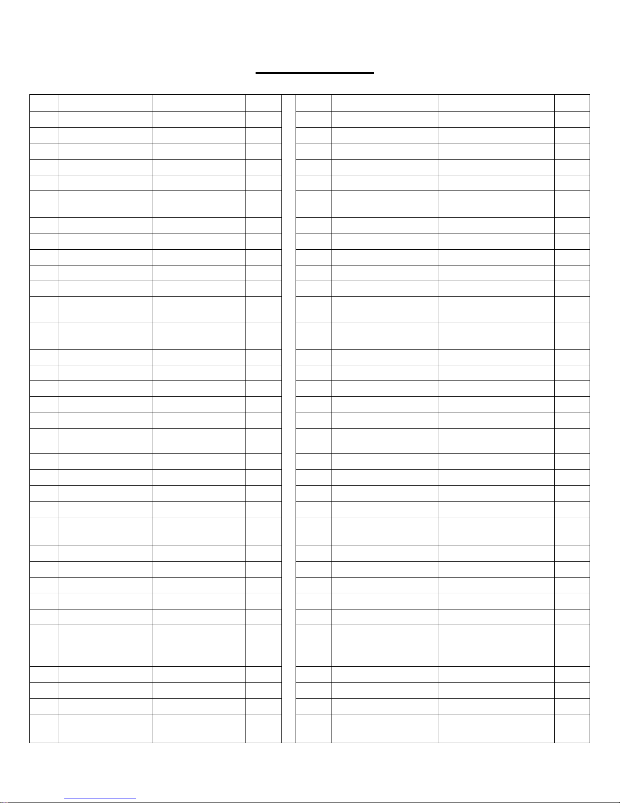
PARTS LIST
No. Description Spec. Qty.
6
12 Bushing
13
125*80*42 1 40 End Cap Φ22*16 2
3 46 Screw ST4.8*10*Φ8 1
3 47 Flywheel 13*Φ450 1
No. Description Spec. Qty.
19
24
30 Middle Axle
1 53 Brake Rod
Φ40.5*Φ8.5*22 2 58 Nut M6*H6*S10 1
Big Chain
1 64 Brake Stopper 35*24*2 1
1
34 Nut
M12*1*H19.5*S
2 68 Bolt M6*12*S10 2
4
Page 6
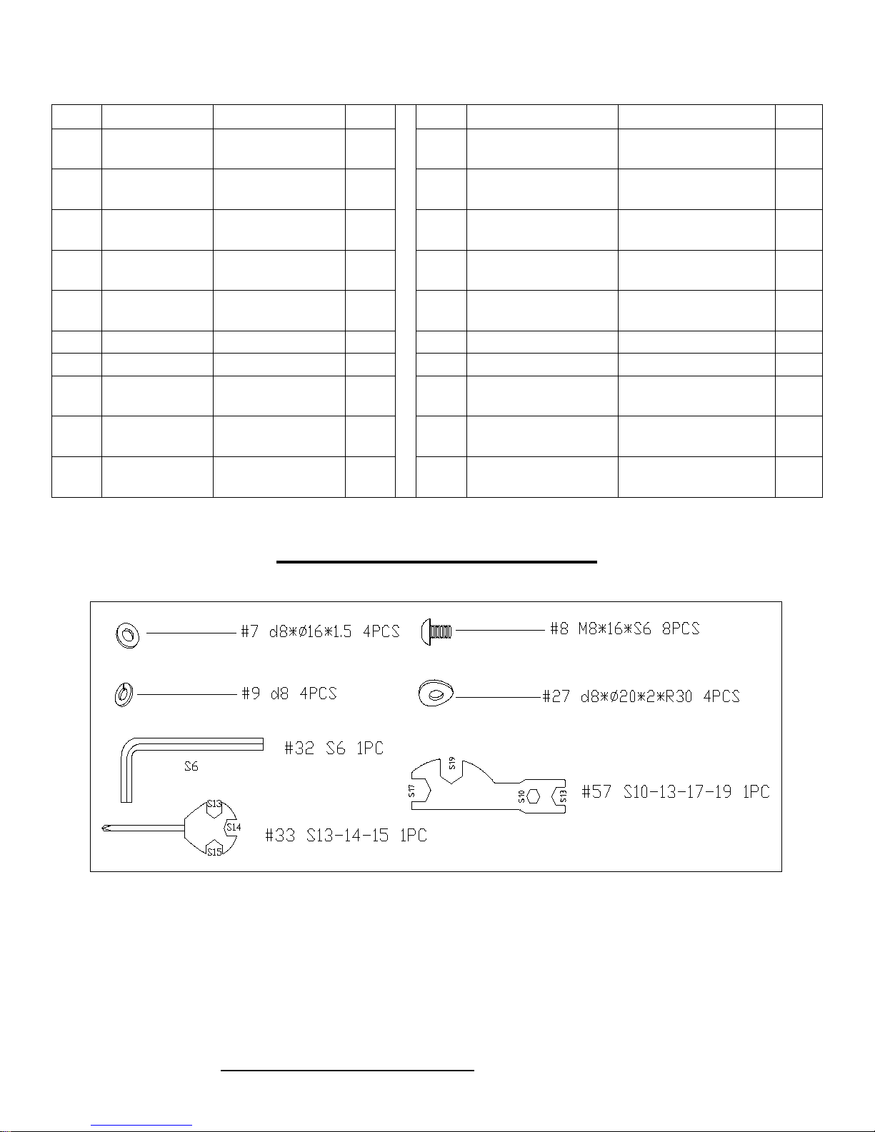
No.
Description
Spec.
Qty.
No.
Description
Spec.
Qty.
Brake Spring
Board
S14
72L/
R
Left & R ight
Crank
Middle Axle
Cover
74
C Clip
d17 1 84
Screw
ST4.2*13*Φ8
8
75
Bearing
6203-2RS
2
85
Screw
ST4.8*16*Φ10
2
Left Nylon
Nut
Right Nylon
Nut
L/R
69
70 Crank Cap Φ25*7 2 80 Chain ½” *1/8” *104 1
71 Nut
73
76
77
78 Bushing 20*20*62 1
t1.2*23*122 1 79 Inner Chain Cover 1
M10*1.25*H7.5*
170 2 82 Crank Cover 100*40 1
Φ50*Φ32*33 1 83 Washer
9/16*20*H8*S19 1 86 Washer
9/16*20*H8*S19 1 87 Blanking Plate
2 81 Outer Chain Cover
88
Pedal YH-76X 9/16" 2
Φ10*1
d5*
Φ16*1.5
d6*
HARDWARE PACKAGE
1
7
2
1
Ordering Replacement P ar t s (U. S. and Cana dian Customers onl y)
Please provide the following information in order for us to accurately identify the part(s) needed:
The model number (found on cover of manual)
The product name (found on cover of manual)
The part number found on the “EXPLODED DIAGRAM” and “PARTS LIST” (found near the
front of the manual)
Please contact us at [email protected] or 1- 877 - 90SUNNY (877-907-8669).
5
Page 7
Φ
STEP 2:
into its
into its
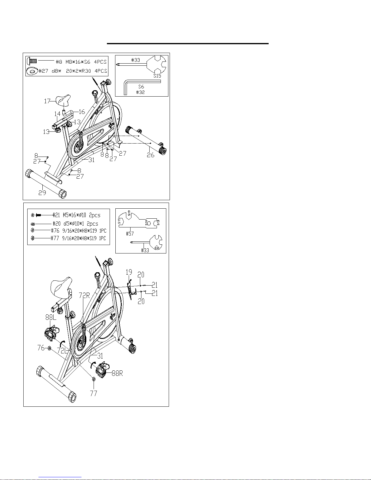
STEP 1:
ASSEMBLY INSTRUCTIONS
Attach the Front and Rear Stabil izers (No. 2 6 and No.
29) to the Main Frame (No. 31) using 4 Screws (No.
8) and 4 Arc Washers (No. 27). Tighten and secure
with Allen Wrench (No. 32).
Attach the Seat (No. 17) to the Seat Slider (No.16),
tighten and secure with Spanner (No. 33).
Loosen and pull out the Adjustment Knob (No. 13).
Adjust the Seat Slider (No. 16) and Seat Post (No. 14)
to the desired position and reinsert and tighten
Adjustment Knob (No. 13) to secure the posts in
place.
WARNING! Read instructions carefully as improper
assembly may ca use p ermanent d amage to y our bike.
(Before you begin, immobilize the cranks by turning
the tension knob all the way to the right).
Remove 2 Left and Right Nylon Nuts (No. 76 and
No. 77) located on Pedals (No. 88 L/R). Attach Left
Pedal (No. 88L) counter-clockwise
corresponding Left Crank ( No. 72L). Once s crewed in
place, use Spanner (No. 33) to hold the bolt of the
pedal then attach Left Nylon Nut (No. 76) clockwise
onto the thread end of the Left Pedal (No. 88L).
Secure with Spanner (No. 57).
Attach Right Pedal (No. 88R) clockwise
corresponding Right Crank (No. 72R). Once screwed
in place, use Spanner (No. 33) to hold the bolt of the
pedal then attach Right Nylon Nut (No. 77) counter-
clockwise into the thread end of the Right Pedal (No.
88R). Secure with Spanner (No. 57).
Remove pre-assembled 2 Screws (No. 21) and 2
Washers (No. 20) from Main Frame (No. 31) with
Spanner (No. 33). Then attach Water Bottle Holder
(No. 19) onto Main Frame (No. 31) using 2 Screws
(No. 21) and 2 Washers (No. 20) that were removed.
Tighten and secure with Spanner (No. 33).
6
Page 8
I
II
III
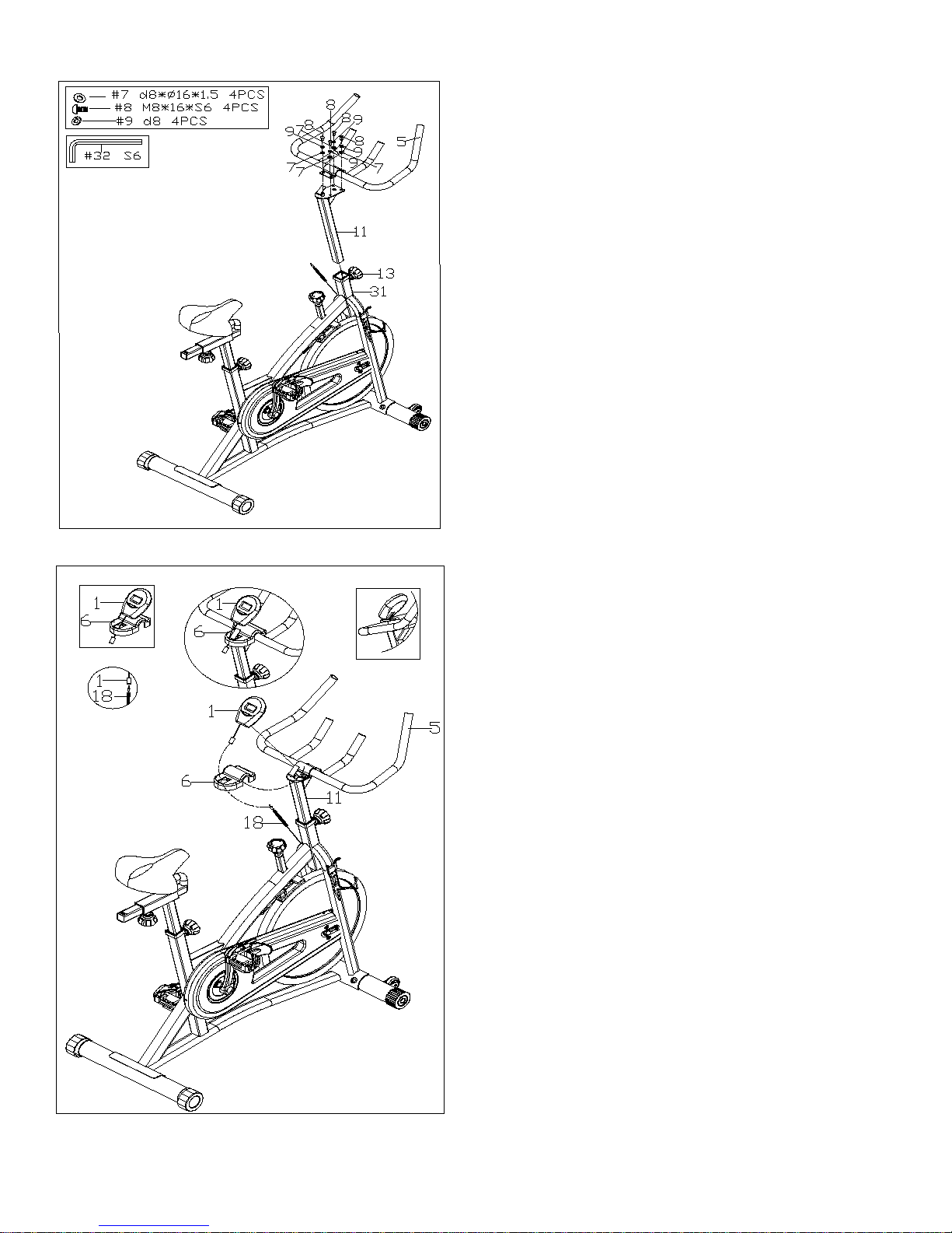
STEP 3:
STEP 4:
to the
as shown in
Loosen and pull out the Adjustment Knob (No. 13).
Insert the Handlebar Post (No. 11) into the sleeve
located on the front of the Main Frame (No. 31).
Adjust the Handlebar Post (No. 11) t o the desired
position, re-inser t a nd tighten the Adjustment Knob
(No. 13) to secure the post in place.
Attach the Handlebar (No. 5) to the Handlebar Post
(No. 11) using 4 Screws (No. 8), 4 Spring Washers
(No. 9) and 4 Washers (No. 7). Tighten and secure
with Allen Wrench (No. 32).
Insert the link w i r e of t he Computer (No. 1) i nto the
middle hole of the Handlebar Cover (No. 6) as
shown in (Picture I).
Attach the Handlebar Cover (No. 6)
Handlebar (No. 5) as shown in (Picture II).
Attach the Computer (No. 1) to the bracket located
on the Handlebar Post (No. 11)
(Picture III).
Connect the li nk wire of the Computer (No. 1) to the
Inductor (No. 18).
The Assembly is complete!
7
Page 9
11
13
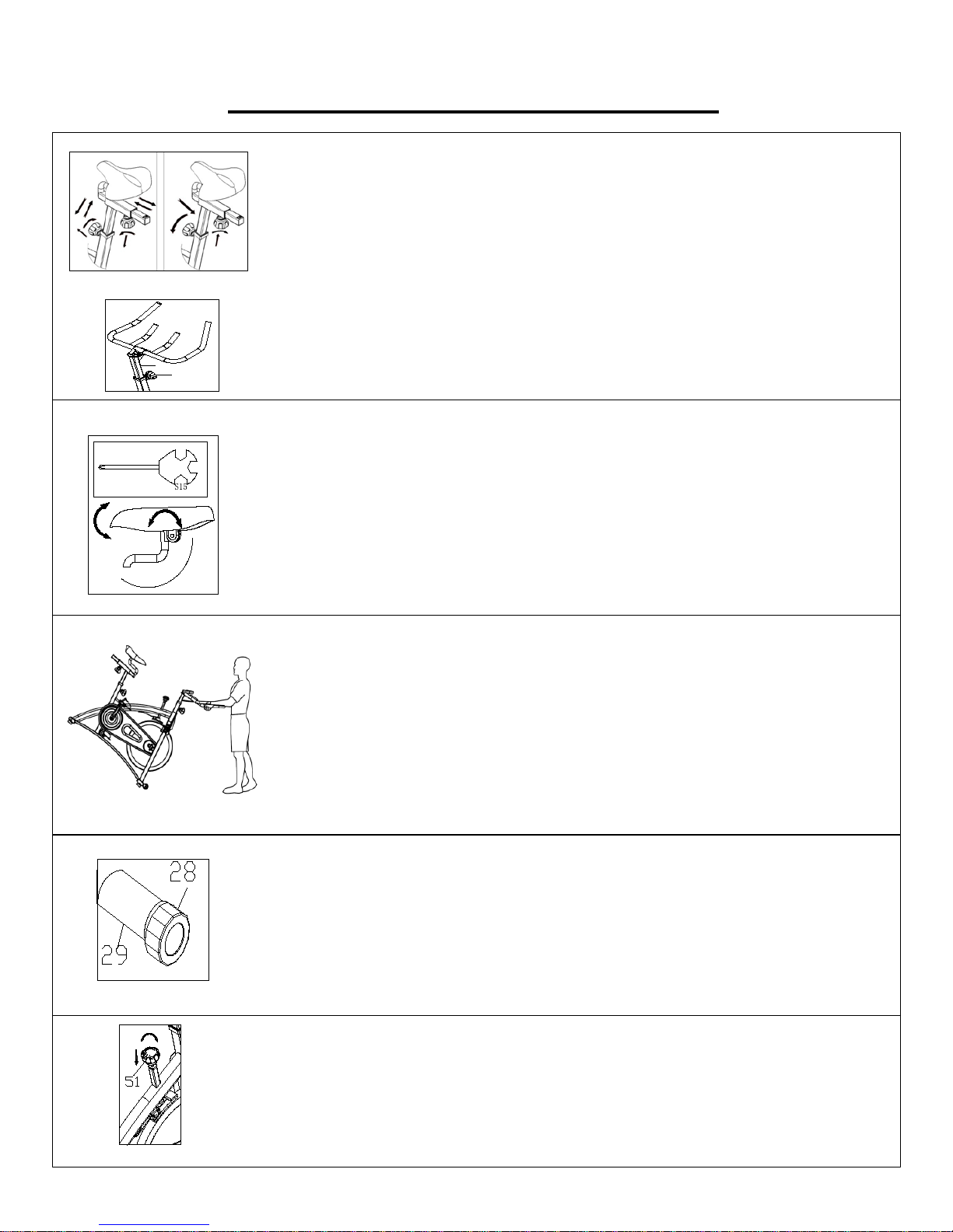
ADJUSTING THE HEIGHT
to ensure that they are fully secure when you finish making an
adjustment.
MOVING THE BIKE
ground, you can transport the bike to the desired location with ease.
ADJUSTING THE ANGLE OF SEAT
on each side simultaneously working in opposite direction of each other.
ADJUSTING THE TENSION & EMERGENCY STOP
ADJUSTING THE BALANCE
until the bike becomes level with the floor surface.
ADJUSTMENTS & USAGE GUIDE
Loosen and pull out the [seat height] Adjustment Knob (No. 13) to adjust
the height of the saddle. You may also slide the seat forward or backwards
by loosening and pulling out the [seat] Adjustment Knob (No. 13) on the
Seat Slider (No. 16). You may adjust the height of the handlebar by using
the [handlebar] Adjustment Knob (No. 13). When making adj ustments, y ou
will see a limit on the saddle post, seat slider and handlebar post. Do NOT
lift the posts passed this mark. Always check the Adjustment Knob (No.
13)
Use Spanner (No. 33) to unscrew the nut under the saddle. Adjust the
saddle to the desired angle and re-install and secure the nut. Check the nut
periodically to ensure that it is tight and secure. Use the Spanner (No. 33)
to tighten when necessary.
Note: In order t o pro per ly tighten the seat, it is impor tant to no te t hat y ou wil l
need two Spanner (No. 33) (1 for each si de) and w il l nee d to tig hten t he nut
To move the bike, first ensure that the handlebar is properly secured. If the
handlebar is loose, tig hten the Adjustment Knob (No. 13) to secure it. Nex t,
stand at the front of the bike so that you’re directly in front of the handlebar.
Firmly grab and hold each side of the Handlebar (No. 5), place one foot on
the front stabilizer and tilt the bike towards you until the transportation
wheels on the front stabilizer touch the ground. With the wheels on the
In order to achiev e a s mooth and com forta ble ri de, y ou must e nsure that the
stability of the bike is secured. If you notice t hat the bike i s unbalanced dur ing
use, you should adjust the end caps located on th e r ear stabilizer. To do so,
simply rotate the End Caps (No. 28) located on the Re ar Stabiliz er (No . 29)
Adjusting tension by rotating the Tension Knob (No. 51) clockwise to
increase the level of resistance. Rotate the knob counter-clockwise to
decrease the level of resistance. Push down on Tension Knob (No. 51) to
enforce the brake and stop the bike immediately.
8
Page 10
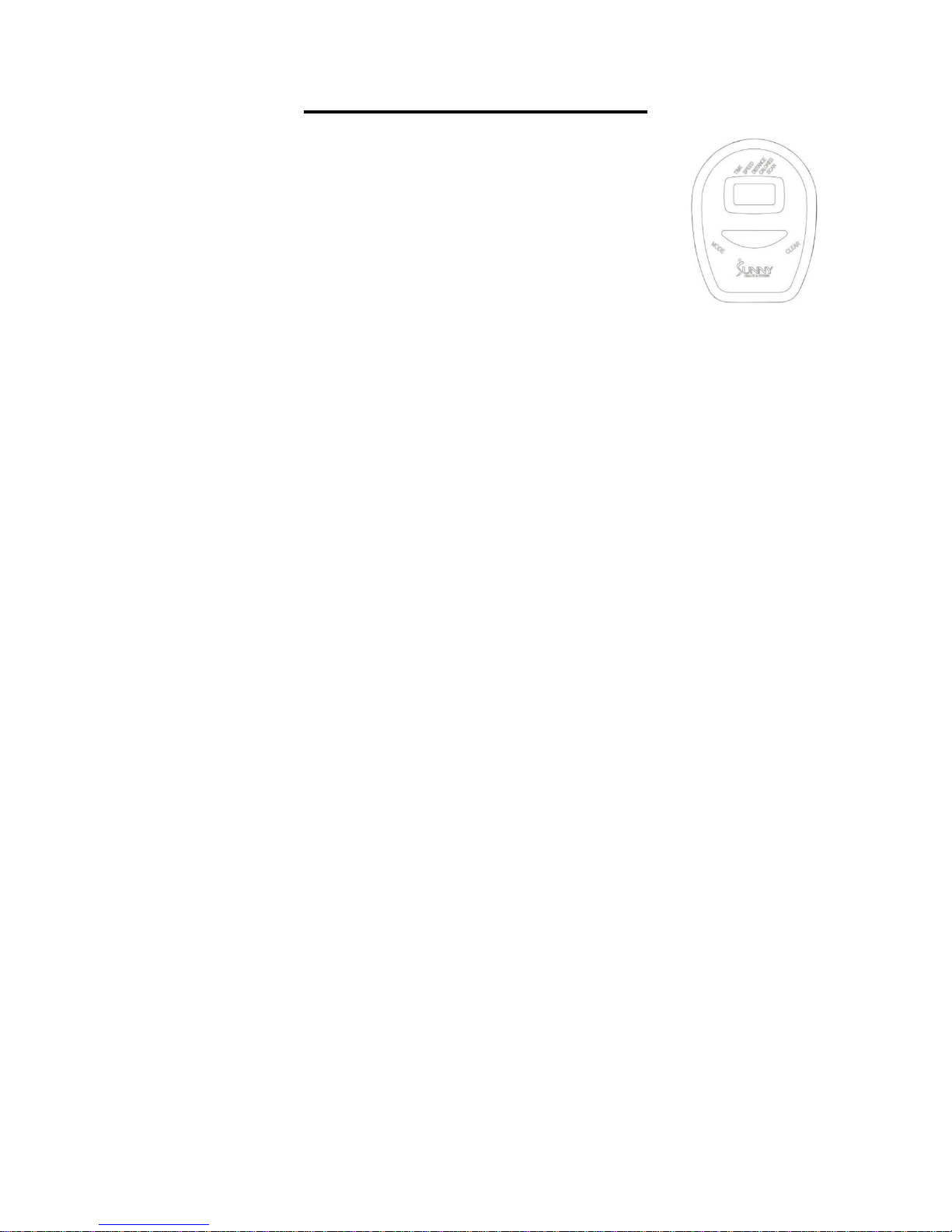
EXERCISE COMPUTER
SPECIFICATIONS:
TIME------------------------------------------- 00:00-99:59 MIN: SEC
SPEED---------------------------------------- 0.0-999.9 ML/H
DISTANCE----------------------------------- 0.00-99.99 ML
CALORIES----------------------------------- 0.0-999.9 KCAL
FUNCTION KEY:
MODE: Press MODE repeatedly to select the desired display value (Time, Speed, Distance,
Calories, Scan).
CLEAR: To reset a single value press CLEAR once. To reset all values Press and hold CLEAR for 3
seconds. This function is only available when the bike is stopped and the computer is not in
SCAN mode.
OPERATION PROCEDURES:
1. AUTO ON/OFF: If the belt is put into motion or the MODE button is pressed, the computer will
activate and will remain active unless there is without a signal for approximately 4 minutes. The
monitor power will turn off automatically.
2. LOCK VALUE SETTING: Press the MODE when the indicator arrow is on the chosen value
(Time, Speed, Distance, Calories, Scan) and then release. Once locked, only the selected
function will be displayed.
FUNCTIONS:
TIME: Counts the total time of an exerci se from start to finish.
SPEED: Displays the current speed being obtained.
DISTANCE: Counts the total distance of an exercise from start to finish.
CALORIES: Counts the total amount of calories burned during an exercise session from start to
finish.
SCAN: Automatically displays functions in the following order shown: Ti me, Spe ed, Distance,
Calories (repeat).
Battery: This monitor uses two AA batteries. If the display appears incorrectly or becomes
difficult to read please install new batteries. Always change both batteries at the same time. Do
not mix battery types and do not mix old and new batteries. Dispose of batteries according to
your state and regional guidelines.
9
Page 11

DAILY MAINTENANCE
equipment: seat, frame, handlebars. Pay
post and belt/chain guard. Sweat is very
corrosive and may cause problems that
bracket, or adjust the drive belt/chain
MONTHLY MAINTENANCE
WEEKLY MAINTENANCE
Inspect moving parts and tighten the
Brush and treat the resistance pads.
LEATHER BRAKE PAD CARE (If Applicable)
lubricated. Squeeze the brake pad. If
5 times until the pad is
Version:3.2
MAINTENANCE INSTRUCTIONS
This is general information for daily, weekly and monthly maintenance to be performed on your bike.
After each ex ercise sessi on, wipe dow n all the
special attention to the seat post, handlebar
require parts replacement later.
1. Get on the bike and engage the drive
train.
2. Pay attention to any vi brations felt throug h
the pedals. If you feel any vibrations, you
may need to tighten the pedals, bottom
tension.
3. Use a wrench to tighten the pedals until
they are secure.
1.
hardware.
2. Inspect pull pin frame fittings to make sure
the fittings are snug. Loose frame fittings
may strip out t hreads o ver time an d cause
extensive damage.
3. Clean and lubricate pop pin assemblies.
Pull on the pin and spray a small amount
of lubricant onto the s haft.
4. Tigh ten the seat hardware to make sure
the seat is level and centered.
5.
Remove any foreign material that may
have collected on the pads. Spray the
pads with silicone lubricant. This helps to
reduce noise from friction between the
pads and the flywheel.
6. Visually inspect the bottom bracket, toe
clips and toe straps. If any of them are
loose or disconnect ed, attac h and tig hten.
1. Check if all hardware is secure, such as:
water bottle holder, flywheel nuts, belt/chain
guard bolts, br ake caliper loc k nuts and br ake
caliper tension rod nuts.
2. Inspect the brake tension rod for signs of
wear such as missing threads. Clean and
lubricate the brake tensi on rod.
3. Clean and lubricate the seat post, handlebar
post and seat slider. Remove any build up of
foreign material.
1. Perform this maintenance when the brake
pad is first installed and for the life of the
brake pad. Follow ing these simple g uidelines
can increase the life of your brake pads.
2. Some brake pad assemblies are prelubricant is released, then the pad has been
pre-lubricated.
3. If the brake pad is dry, then coat the brake
pad with 3-n-1 oil. Brush the leather with a
clean, wire bristle brush, and then apply the
oil. The oil should be al lowed to soak i n to the
pad. Repeat 4saturated, but not dr i p pi ng with oil. When the
pad is saturated, it will no longer absorb oil.
4. Inspect the brake pad weekly and lubricate if
needed. The pad should not have a glazed
appearance. If the pad appears glazed, then
brush it with wire brush and apply lubricant
as needed. If any of the sponge padding is
showing through the leather pad, the brake
pad should be replaced.
10
 Loading...