

Page 1

IINNDDOOOORR CCYYCCLLIINNGG BBIIKKEE
SSFF--BB11111100SS
OOWWNNEERR’’SS MMAANNUUAALL
IMPORTANT!
PLEASE READ THIS MANUAL CAREFULLY BEFORE USING THE BIKE.
For Customer Service, please contact: support@sunnyhealthfitness.com
Page 2

Important Safety Information
Please keep this manual for future reference!
1. It is important to read this entire manual before assembling and using the
equipment. Safe and effective use can only be achieved if the equipment is
assembled, maintained and used properly. It is your responsibility to ensure
that all users of the equipment are informed of all warnings and precautions.
2. Before starting any exercise program you should consult your doctor to
determine if you have any medical or physical conditions that could put your
health and safety at risk, or prevent you from using the equipment properly.
Your doctor’s advice is essential if you are taking medication that affects
your heart rate, blood pressure or cholesterol level.
3. Be aware of your body’s signals. Incorrect or excessive exercise can
damage your health. Stop exercising if you experience any of the following
symptoms: pain, tightness in your chest, irregular heartbeat, extreme
shortness of breath, lightheadedness, dizziness or feelings of nausea. You
should consult your doctor before continuing with your exercise program. If
you do experience any of these conditions.
4. Keep children and pets away from the equipment. The equipment is
designed for adult use only.
5. Use the equipment on a solid, flat level surface with a protective cover for
your floor or carpet. The equipment should have at least 0.5 meters of free
space all around to ensure the safety.
6. Check all the nuts and bolts are securely tightened before using the
equipment.
7. The safety of the equipment can only be maintained if it is regularly
examined.
8. Always use the equipment as indicated. If you find any defective
components while assembling or checking the equipment, or if you hear any
unusual noises coming from the equipment during exercising, stop using the
equipment immediately and don’t use the equipment until the problem has
been repaired.
9. Wear suitable clothing while using the equipment. Avoid wearing loose
clothing that may get caught in the equipment
10. The maximum weight capacity of this unit is 265 pounds.
11. The equipment is not suitable for therapeutic use.
12. You must take care of yourself when lifting and moving the equipment so as
not to injure your back. Always use proper lifting technique and seek
assistance if necessary.
13. This equipment is designed for indoor and home use only, not intended for
commercial use.
1
Page 3
69
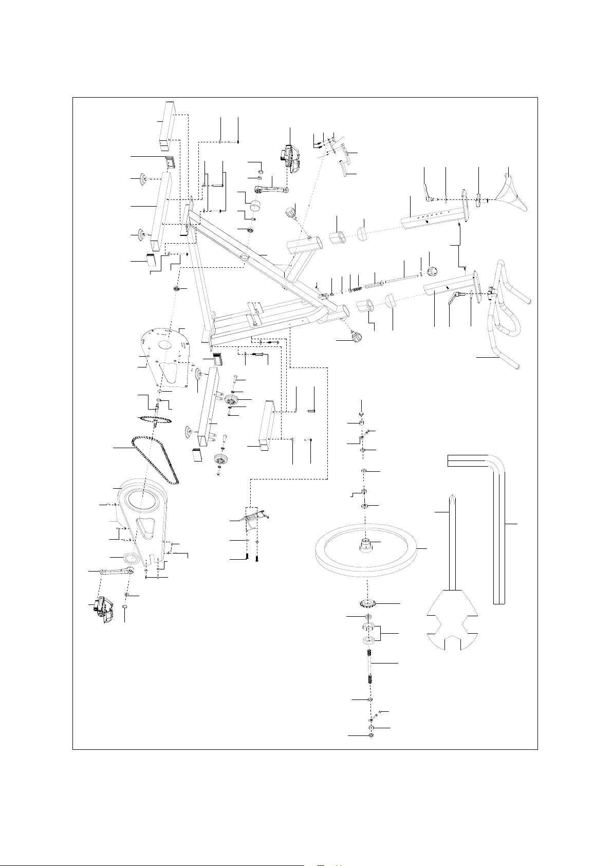
EXPLODED VIEW
70
4
9L
50
51
71
47
21
32
42
55
54
44
46
48
75
52
31
74
32
53
56
1
3
2
3
1
70
4
73
18
19 20
1416
15
17
4
5
11
10L
12
13
14
15
64
1
3
6
4
33
69
69
5
7
8
25
8
38
4
49
40
70
45
38
31
43
30
42
29
41
36
28
34
29
28
35
27
26
10R
9R
23
22
73
23
58
11
12
72
24
73
23
39
67
68
70
4
57
60
56
52
56
60
61
66
65
62
63
37
59
53
55
2
Page 4

PARTS LIST
NO DESCRIPTION QTY NO DESCRIPTION QTY
1 End cap F80*40 4 39 Bottle holder 1
2 Rear stabilizer 1
3 Foot pad 4 41 Knob M10 1
4 Washer d8*φ16*1.5 8 42 Nut M10 2
5
6
7 Screw Φ7.8*30*M6*15*S5 2
8 Bearing ABEC-5 φ8 4
9L/R Pedal 2
10L/R Crank 2
11 End cap 2 49 Screw M5*10*φ8.5 2
12 Nut M10*1.25 2
13 Cover for middle axle 1
14 Jump ring d20 2
15 Bearing 6004-2RS 2
16 Wave washer d20*Φ25*0.3 1 54 Adjusting screw M6*60*φ12*5 2
17 Inner chain cover 1
18 Screw ST4.8*16 2
19 Middle axle Φ20*190 1
20 Chain wheel φ225*2.5*Z52 1
21 Drive chain 1/2*1/8*104 1
22 Outer chain cover 1
23 Screw ST4.2*13 5 61 Bushing 1
24 Screw M6*10 2 62 Flywheel 1
25 Transport wheel φ71*φ19*24 2 63 Chain wheel 1
26 Saddle 1
27 Saddle column 1
28
29 L shape knob M10*25 2 67 Washer d5*φ10*1
30 Saddle post 1
31 End cap PT70*30 2
32 Bushing PT80*40*L130 2
33 Screw M6*12*S5 2
34 Screw M5*10 2
35 Handle bar 1
36 Handlebar post 1
37 Nut 2
38 Knob M16*1.5*27 2
Screw M8*55
Front stabilizer
Washer d10*φ40*4
4 43 Brake rod φ10*210 1
1
2
40 Screw M6*12*Φ12 1
44 Square nut 1
45 Nut M6*H14*S10 1
46 Brake board t7*138.3*28 1
47 Spring piece t1.5*110*15.5 1
48 Woolen felt 1
50 Bolt M6*10*S10 2
51 Washer d6*φ12*1.2 2
52 Nut M12*1 2
53 Nut M6 4
55 Spacer φ18*φ12.2*6 2
56 Nut M12*1 3
57 SpacerΦ18*Φ12.1*9 1
58 Crank cover 1
59 Inertia axle φ12*162 1
60 Bearing 6001-RS 2
64 Main frame 1
65 Spanner S6 1
66 Spanner S13-14-15 1
2
68 Screw M5*16 2
69 Shipping tube 2
70 Screw M8*20 4
71 Rubber pad 44*25*3 1
72 Washer d6*φ16*1.2 2
73 Washer d5*φ10*1 7
74 Spacer 20*20*75 1
75 Spring Φ2.0*Φ15*54*N12 1
3
Page 5
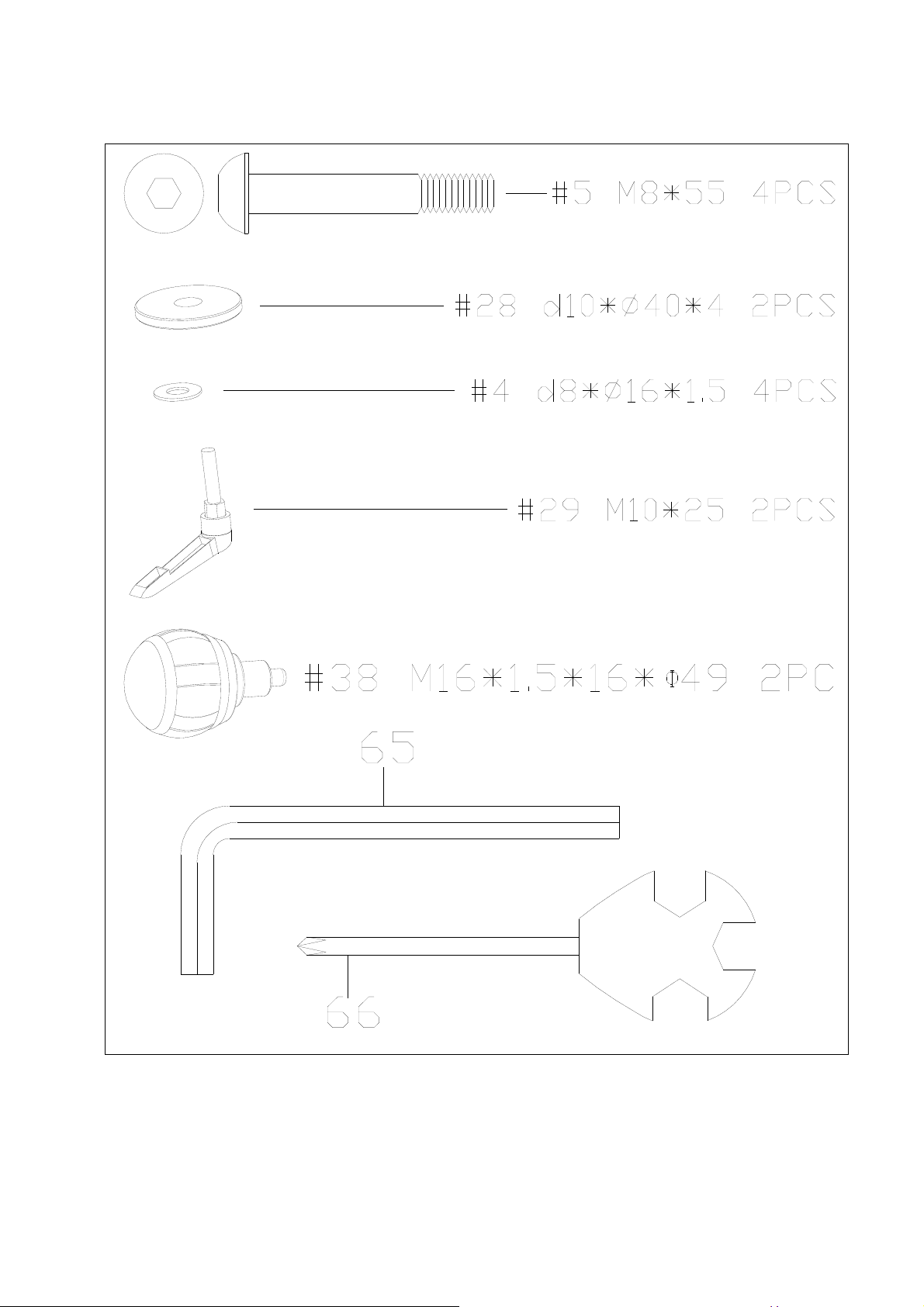
HARDWARE PACKAGE
4
Page 6

STEP 1:
ASSEMBLY INSTRUCTIONS
64
70
70
4
4
69
69
A: Remove the shipping tubes (69) from main frame (64) by unscrewing the
screws (70) and washers (4) with Allen wrench (65).
B: You can save these parts for future packaging and transportation of the bike
if desired. {screws (70), washers (4), the shipping tube (69) }
5
Page 7

STEP 2:
64
5
5
4
4
6
2
Attach the front stabilizer (6) and rear stabilizer (2) to main frame (64), secure
each of them together using two hex screws (5) and washers (4).
6
Page 8

STEP 3:
27
30
28
29
64
38
A. Insert the saddle post (30) into the main frame (64) fixing with knob (38).
B. Secure the saddle column (27) onto the saddle post (30) using the L shape
knob (29) and washer (28).
7
Page 9

STEP 4:
35
28
64
29
36
38
A. Insert the handlebar post (36) into the main frame (64) fixing with knob (38).
B. Secure the handle bar (35) onto the handle bar post (36) using the L shape
knob (29) and washer (28).
8
Page 10

STEP 5:
64
9L
39
67
68
10L
10R
9R
IMPORTANT! Read instructions carefully, failure to do so may cause
permanent damage to your bike.
A. Screw the right pedal (9R) into the crank shaft (10R) in the CLOCKWISE
direction. Screw the left pedal (9L) into the crank shaft (10L) in the
COUNTER-CLOCKWISE direction. You must use a spanner (66) to tighten
securely.
B. Remove the two screws (68) and two washers (67) located on the main
frame (64). Then secure the bottle holder (39) to the main frame (64) using
screws (68) and washers (67) that you had just previously removed.
9
Page 11

OPERATION
Leveling the bike
This bike can be leveled to compensate
for uneven surfaces. To level the bike,
please raise or lower the four leveler feet
located on the underside of the front and
rear stabilizers. (Fig.1)
Resistance Adjustment
Fig.1
Pedaling resistance is controlled by the
tension control knob (Fig.2). To increase
resistance, turn the tension control knob
clockwise (+). To decrease resistance, turn
the tension control knob counter-clockwise (-).
Resistance adjustment can be easily made at
any time. Emergency brake is also equipped
in this machine, by pushing down the knob,
you can stop the transmission immediately.
(Fig.3)
10
Fig.2
Fig.3
Page 12

Seat Adjustment
Appropriate seat height helps ensure your
exercise efficiency, reduce the risk of injury
and makes you feel more comfortable.
Adjusting the seat forward or backward helps
you work on different lower body muscle
groups.
1. Place one pedal in the upward position.
Place your foot in the toe clips, then get on the
bike.
2. If your leg is bent too much, you should
move the seat up. If your foot can not touch
the pedal or your leg is too straight, you should
move the seat down.
3. Dismount the bike. Loosen and pull the pop
pin (Fig.4), then raise or lower the seat post to
the desired position. Make sure the pop pin
settles into the desired hole and then secure it
firmly.
4. Loosen the L shape knob (Fig.5), then
Fig.4
move the seat forward or backward to the
desired position. When the seat slider is in the
desired position, secure the L shape knob
clockwise firmly.
11
Fig.5
Page 13

Handlebar Adjustment
1. Loosen and pull the pop pin (Fig.6), then raise
or lower the handlebar to the desired position for
a more efficient & comfortable ride. Make sure
the pop pin settles into the desired hole and then
secure it firmly.
2. Loosen the L shape knob (Fig.7), then move
the handlebar forward or backward to the desired
position. When the handlebar is in the desired
position, secure the L shape knob clockwise
firmly.
Important!
1. If the L shape knob touches the tube when
securing clockwise, please pull down the L shape
Fig.6
Fig.7
knob and turn it counter-clockwise, then release it
and secure it clockwise. Repeat it several times
until you secure it firmly.
2. If the L shape knob touches the tube when
releasing counter-clockwise, please pull down the
L shape knob and turn it clockwise, then release it
and secure it counter-clockwise. Repeat it several
times until you can move the handles to desired
position.
12
Page 14

Pedal Strap Adjustment
Place the ball of each foot in the toe clip until the
front of the shoe fits snugly in the toe clip cage.
Rotate one foot to within arm’s reach, then pull up
the strap until the toe clip cage fits the shoe
snugly (Fig.8) and insert the strap back into the
hoop of toe clip. Repeat for the other foot.
Workout
Once you are sitting comfortably, begin pedaling
slowly, with your hands resting comfortably on the
handlebar. After you feel secure, you can change
seat positions, hand positions and resistance
levels for added enjoyment and variety during your
workout.
Dismounting the bike
You can stop the flywheel’s motion abruptly by
pushing down the tension knob (see page 11,
figure 3). Also you can increase the resistance by
turning the tension control knob clockwise until the
flywheel stops, or pedal slower until you come to a
complete stop.
13
Fig.8
Page 15

Warning!
Do not dismount the bike or remove your feet from
the pedals until the pedals have completely
stopped.
Moving the Bike
Carefully press down from the front of the
handlebar to move the bike to another location
(Fig.9). Please gently move the bike as any sudden
impact may affect the operation of the machine.
Fig.9
th
Version: Jan 11
,2014
14
 Loading...