

Page 1
Page 2
Page 3
Page 4

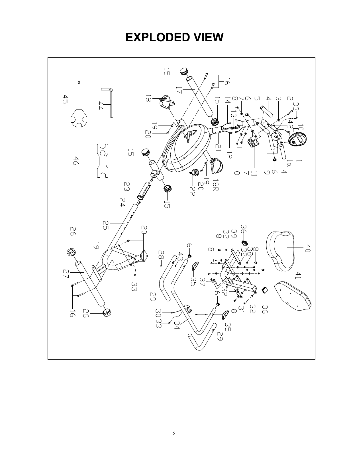
PARTS LIST
No. Description Qty. No. Description Qty.
1 Computer 1 24 Sensor wire 5 1
1a Computer wire 1 25 Rear main frame 1
2 Screw M5*15 1 26 End cap Φ50 2
3 Arc washer d5*Φ20*1*R30 1 27 Rear stabilizer 1
4
Foam grip Φ23*5*120
5
Handlebar post
6 End cap Φ25*16 4 30 Handle pulse wire 1
7 Arc washer d8*Φ20*2*R30 4 31 Nut M8 2
8 Screw M8*16 16 32 Washer d8*Φ16*1.5 14
9 Sensor wire a 1 33 Grommet Φ12*Φ11*3 3
10 Sensor wire b 1 34 Handle bar 1
11 Tension control cable 1 35 Handle pulse 2
12 Sensor wire c 1 36 End cap F38*38*1.5 2
13 Tension hook 1 37 Bolt M8*50 2
14 Sensor wire d 1 38 Spring washer d8 4
15 End capΦ50 4 39 Backrest frame 1
16 Bolt M10*60 4 40 Seat cushion 1
17 Front stabilizer 1 41 Backrest cushion 1
2 28 Screw ST4*19 2
1 29 Foam grip Φ23*5*500 2
18L/R Pedal L/R 2 42 Screw M5*10 2
19 Arc washer d10*Φ25*2*R30 4 43 Washer d6*Φ12*1 2
20 Nut M10 4 44 Allen wrench S6 1
21 Main frame 1 45 Spanner S13-14-15 1
22 Knob M16*1.5*27 1 46 Spanner S17-19 1
23 Bushing Φ50 1
3
Page 5

HARDWARE PACKAGE
4
Page 6

Step 1:
ASSEMBLY INSTRUCTIONS
Secure Front stabilizer (17) to Main frame (21) with Bolts (16), Arc washers (19) and
Nuts (20).
5
Page 7

Step 2:
a
b
A. Connect Sensor wire a (9) with Sensor wire c (12). Then connect Sensor wire b
(10) with Sensor wire d (14).(See diagram a above)
B. Connect Tension hook (13) with Tension control cable (11).(See diagram b above)
C. Secure Handlebar post (5) to Main frame (21) with Screws (8) and Arc washers
(7).
6
Page 8

Step 3:
A. Connect Computer wire (1a) with Sensor wire a (9), then secure Computer (1) to
Handlebar post (5) with Screws (42). Insert Sensor wire b (10) into the back of
Computer (1).
B. Secure Pedals (18L/R) onto the left and right crank of the Main frame (21).
★CAUTION: The left side of the machine has reversed threading. You must
screw the left pedal counter-clockwise to tighten. The right pedal is tightened by
turning clockwise. Failure to follow these instructions can result in permanent
damage to your bike.
7
Page 9

Step 4:
A. Secure the Rear stabilizer (27) to the Rear main frame (25), with Bolts (16), Arc
washers (19) and Nuts (20).
B. Secure Backrest frame (39) to
Rear main frame (25) with Screws (8), Spring
washers (38) and Washers (32).
★Note: For easier installation of next step, try flipping Rear main frame (25)
over.
C. Secure Seat cushion (40) and Backrest cushion (41) to Backrest frame (39) with
Screws (8) and Washers (32).
8
Page 10

Step 5:
A. Connect Sensor wire d (14) with Sensor wire 5 (24), then secure the Rear main
frame (25) to the Main frame (21) with the Knob (22).
★CAUTION: There are different holes on the Rear main frame (25) which can
be used for people with different height. You can find the best position hole for
your height. At the farthest point of the pedal’s travel, your knee should still
have a slight 15 degree in it.
9
Page 11

Step 6:
A. Secure Handle bar (34) to Backrest frame (39) with Bolts (37), Washers (32) and
Nuts (31).
B. Connect Sensor wire 5 (24) with Handle pulse wire (30).
Installation is complete.
Version: Jan.10th, 2014
10
 Loading...