

Page 1

Page 2

• •
Important Safety Information
We thank you for choosing our product. To ensure your safety and health, please use
this equipment correctly. Please read the information below carefully before using this
equipment.
1. It is important to read this entire manual before assembling and using the equipment.
Safe and effective use can only be achieved if the equipment is assembled,
maintained and used properly.
2. Before starting any exercise program you should consult your doctor to determine if
you have any medical or physical conditions that could put your health and safety at
risk, or prevent you from using the equipment properly. Your doctor’s advice is
essential if you are taking medication that affects your heart rate, blood pressure or
cholesterol level.
3. Be aware of your body’s signals. Incorrect or excessive exercise can damage your
health. Stop exercising if you experience any of the following symptoms: pain,
tightness in your chest, irregular heartbeat, extreme shortness of breath,
lightheadedness, dizziness or feelings of nau
conditions, you should consult your doctor before continuing with your exercise
program.
4. Keep children and pets away from the equipment. The equipment is designed for
adult use only.
5. Use the equipment on a solid, flat level surface with a protective cover for your floor
or carpet. To ensure safety, the equipment should have at least 0.5 meters of free
space all around it.
6. Before using the equipment, please make sure all the nuts and bolts are securely
tightened. Always use the equipment as indicated. If you find any defective
components while assembling or checking the equipment, or if you hear any
unusual noises coming from the equipment during use, stop immediately. Do not
use the equipment until the problem has been rectified.
7. There are many functions of the computer; the data will show when using the
equipment
the heart pulse monitor is solely to provide some reference.
8. Wear suitable clothing while using the equipment. Avoid wearing loose clothing that
may get caught in the equipment or that may restrict or prevent movement.
9. The maximum weight of
10. Care must be taken when lifting or moving the equipment so as not to injure your
back.
11. The equipment is not suitable for therapeutic use.
12. Please keep this manual and the assembling tools.
13.This equipment is designed for indoor and home use only, not intended for commercial
use.
and will display information about your exercise routine. Please note that
user: 220LBS.
sea. If you do experience any of these
1
Page 3
2
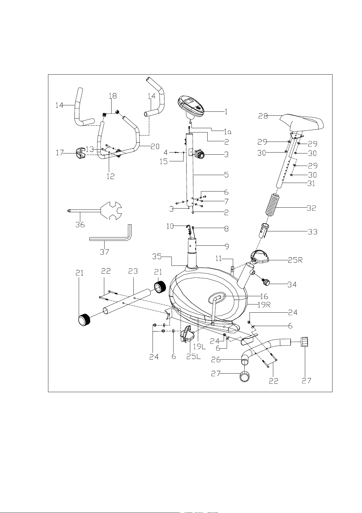
EXPLODED VIEW
Page 4

3
PARTS LIST
No. Description Qty. No. Description Qty.
1
1a
2
3
4
5
6
7
8
9
10
11
12
13
Computer
Computer wire 1
Trunk line
8- Level Tension control
Screw M5*15
Handlebar post
Arc washer d8*Φ20*2*R30
Screw M8*16
Sensor wire
Main frame
Tension control wire (down
side)
Crank
Spring washer d8
Screw M8*30
1 27
1 28
1 29
1 30
1 31
1 32
8 33
4 34
1 35
1 36
1 37
1
2
2
End cap Φ50 2
Saddle 1
Washer d8*Φ16*1.5 3
Nylon Nut M8 3
Saddle tube 1
Stretch pipe 1
Bushing Φ50 1
Knob M16*1.5*22 1
Decoration cover 1
Spanner S13-14-15 1
Allen wrench S6 1
14
15
16
17
18
19L/R
20
21
22
23
24
25L/R
26
Foam grip Φ23*25*445
Arc-washer d5*Φ20*1.5*R30
Crank cover
Cover
End cap Φ25*16
Chain cover L/R
Handlebar
Rolling end cap Φ50
Carriage bolt M8*60
Front stabilizer
Nut M8
Pedal L/R
Rear stabilizer
2
1
2
1
2
2
1
2
4
1
4
2
1
Page 5

4
HARDWARE PACKAGE
Page 6

Step 1:
5
ASSEMBLY INSTRUCTIONS
A. Attach the Front stabilizer (23) and Rear stabilizer (26) to the Main
frame (9) fixing with the 4 sets Carriage bolt (22), Arc-washers (6) and
Nuts (24).
B. Attach the Pedals(25L/R)to the *left and right side of Crank (11).
* IMPORTANT
counter-clockwise
cause permanent damage to your bike.
: Left crank has reversed threading; you must screw pedal
to tighten. Failure to follow installation instructions may
Page 7

Step 2:
6
Fix the Saddle (28) to the Saddle tube (31) with the Nylon nuts (30) and
Washers (29).
Page 8

Step 3:
7
A. Connect the bottom of the Tension control wire (10) with the Tension
control (3) and connect the Sensor wire (8) with Trunk line (2).
NOTE : Please make sure the Tension control (3) is at the lowest tension level before you begin.
*
This will ensure the wires are at their longest reaching points to make the connection easier.
B. Insert the Handlebar post (5) to the Main frame (9) fixing with 4 sets Screws
(7) and Arc-washers (6).
C. Attach the Stretch pipe (32) to the Saddle tube (31), then insert the Saddle
tube (31) to the Main frame (9) fixing with Knob (34).
Page 9

• •
Step 4:
A. Connect the Computer wire (1a) with the Trunk line (2). Connect the
Computer (1) to the top of Handlebar post (5).
B. Fix the Handlebar (20) to the Handlebar post (5) with the Screws (13)
and Spring washer (12) and attach the Cover (17).
Assembly is complete.
Version: Apr 27th,2013
 Loading...