

Page 1
SUNNEN®PRODUCTS COMPANY • 7910 MANCHESTER ROAD • ST. LOUIS, MO 63143, U.S.A. • PHONE: 314-781-2100
READ THE FOLLOWING INSTRUCTIONS THOROUGHLY AND CAREFULLY BEFORE UNPACKING,
INSPECTING, OR INSTALLING THE SUNNEN®SV-2460 VERTICAL HONING MACHINE.
I-SV-461
Installation, Setup
and Operation
INSTRUCTIONS
for
SUNNEN®VERTICAL HONING MACHINE
Models: SV-2460
“SUNNEN®AND THE SUNNEN LOGO ARE REGISTERED TRADEMARKS OF SUNNEN PRODUCTS COMPANY.”
ORIGINAL INSTRUCTIONS
Page 2

GENERAL INFORMATION
The Sunnen®equipment has been designed and engineered for a wide variety of parts within the capacity and limitation of the equipment. With proper care
and maintenance this equipment will give years of service.
READ THE FOLLOWING INSTRUCTIONS CAREFULLY AND THOROUGHLY BEFORE UNPACKING, INSPECTING, OR INSTALLING THIS EQUIPMENT.
IMPORTANT:
Read any supplemental instructions BEFORE installing this equipment. These supplemental instructions give you important information to
assist you with the planning and installation of your Sunnen equipment.
Sunnen Technical Service Department is available to provide telephone assistance for installation, programming, & troubleshooting of your Sunnen
equipment. All support is available during normal business hours, 8:00 AM to 4:30 PM Central Time. Emergency breakdown support is available on a 24
hour / 7 day basis.
Review all literature provided with your Sunnen equipment. This literature provides valuable information for proper installation, operation, and maintenance
of your equipment. Troubleshooting information can also be found within the Instructions. If you cannot find what you need, call for technical support.
Where applicable, programming information for your Sunnen equipment is also included. Most answers can be found in the literature packaged with your
equipment.
Help us help you. When ordering parts, requesting information, or technical assistance about your equipment, please have the following
information available:
• Have ALL MANUALS on hand. The Customer Services Representative or Technician will refer to it.
• Have Model Number and Serial Number printed on your equipment Specification Nameplate.
• Where Applicable: Have Drive model and all nameplate data. Motor type, brand, and all nameplate data.
For Troubleshooting, additional information may be required:
• Power distribution information (type - delta, wye, power factor correction; other major switching devices used, voltage fluctuations)
• Installation Wiring (separation of power & control wire; wire type/class used, distance between drive and motor, grounding).
• Use of any optional devices/equipment between the Drive & motor (output chokes, etc.).
For fast service on your orders call:
Sunnen Automotive Customer Service toll free at: 1-800-772-2878
Sunnen Industrial Customer Service toll free at: 1-800-325-3670
Customers outside the USA, contact your local authorized Sunnen Distributor.
Additional information available at:
http://www.sunnen.com or e-mail: [email protected]
NOTE: Sunnen reserves the right to change or revise specifications and product design in connection with any feature of our products contained herein.
Such changes do not entitle the buyer to corresponding changes, improvements, additions, or replacements for equipment, supplies or accessories
previously sold. Information contained herein is considered to be accurate based on available information at the time of printing. Should any discrepancy of
information arise, Sunnen recommends that user verify the discrepancy with Sunnen before proceeding.
ESD PREVENTION REVIEW
Let's review the basics of a sound static control system and its effective implementation. First, in the three step plan:
1. Always ground yourself when handling sensitive components or assemblies.
2. Always use a conductive or shielded container during storage or transportation. These materials create a Faraday
cage which will isolate the contents from static charges.
3. Open ESD safe containers only at a static safe work station.
At the static safe work station, follow these procedures before beginning any work:
A. Put on your wrist strap or foot grounding devices.
B. Check all grounding cords to make sure they are properly connected to ground, ensuring the effective dissipation of sta-
tic charges.
C. Make sure that your work surface is clean and clear of unnecessary materials, particularly common plastics.
D. Anti-static bubble wrap has been included for use at the machine when an ESD safe workstation is not available.
You are now properly grounded and ready to begin work. Following these few simple rules and using a little common sense will go a long
way toward helping you and your company in the battle against the hazards of static electricity. When you are working with ESD sensitive devices, make sure you:
GROUND
ISOLATE
NEUTRALIZE
ii
Page 3

SUNNEN®LIMITED PRODUCT WARRANTY
Sunnen®Products Company and its subsidiaries (SPC) warrant that all new SPC honing machines, gaging equipment, tooling, and related equipment will
be free of defects in material and/or workmanship for a period of one year from the date of original shipment from SPC.
Upon prompt notification of a defect during the one-year period, SPC will repair, replace, or refund the purchase price, with respect to parts that prove to be
defective (as defined above). Any equipment or tooling which is found to be defective from improper use will be returned at the customer's cost or repaired
(if possible) at customer's request. Customer shall be charged current rates for all such repair.
Prior to returning any SPC product, an authorization (RMA#) and shipping instructions must be obtained from the Customer Service Department or items
sent to SPC will be returned to the customer.
Warranty Limitations and Exclusions This Warranty does not apply to the following:
• Normal maintenance items subject to wear and tear: (belts, fuses, filters, etc).
• Damages resulting from but not limited to:
› Shipment to the customer (for items delivered to customer or customer's agent F.O.B., Shipping Point)
› Incorrect installation including improper lifting, dropping and/or placement
› Incorrect electric power (beyond +/- 10% of rated voltage) including intermittent or random voltage spikes or drops
› Incorrect air supply volume and/or pressure and/or contaminated air supply
› Electromagnetic or radio frequency interference from surrounding equipment (EMI, RFI)
› Storm, lightning, flood or fire damage
› Failure to perform regular maintenance as outlined in SPC manuals
› Improper machine setup or operation causing a crash to occur
› Misapplication of the equipment
› Use of non-SPC machines, tooling, abrasive, fixturing, coolant, repair parts, or filtration
› Incorrect software installation and/or misuse
› Non-authorized customer installed electronics and/or software
› Customer modifications to SPC software
THE LIMITED WARRANTY DESCRIBED HEREIN IS EXPRESSLY IN LIEU OF ALL ANY OTHER WARRANTIES. SPC MAKES NO REPRESENTATION OR WARRANTY OF ANY
OTHER KIND, EXPRESS OR IMPLIED, WHETHER AS TO MERCHANTABILITY, FITNESS FOR A PARTICULAR PURPOSE OR ANY OTHER MATTER. SPC IS NOT
RESPONSIBLE FOR THE IMPROPER USE OF ANY OF ITS PRODUCTS. SPC SHALL NOT BE LIABLE FOR DIRECT, INDIRECT, INCIDENTAL, OR CONSEQUENTIAL
DAMAGES INCLUDING BUT NOT LIMITED TO: LOSS OF USE, REVENUE, OR PROFIT. SPC ASSUMES NO LIABILITY FOR PURCHASED ITEMS PRODUCED BY OTHER
MANUFACTURERS WHO EXTEND SEPARATE WARRANTIES. REGARDLESS OF ANY RIGHTS AFFORDED BY LAW TO BUYER, SPC's LIABILITY, IF ANY, FOR ANY AND
ALL CLAIMS FOR LOSS OR DAMAGES WITH RESPECT TO THE PRODUCTS, AND BUYER'S SOLE AND EXCLUSIVE REMEDY THEREFORE, SHALL IN ALL EVENTS BE
LIMITED IN AMOUNT TO THE PURCHASE PRICE OF THAT PORTION OF THE PRODUCTS WITH RESPECT TO WHICH A VALID CLAIM IS MADE.
Shipping Damages
Except in the case of F.O.B., Buyer's destination shipments, SPC will not be liable for any settlement claims for obvious and/or concealed shipping damages.
The customer bears the responsibility to unpack all shipments immediately and inspect for damage. When obvious and/or concealed damage is found, the
customer must immediately notify the carrier's agent to make an inspection and file a claim. The customer should retain the shipping container and packing
material.
SUNNEN®SOFTWARE LICENSE AGREEMENT
This document is a Legal Agreement between you, as user and licensee (Licensee), and Sunnen®Products Company (SPC) with respect to preprogrammed
software (Software) provided by SPC for use on SPC Equipment. By using the Software, you, as Licensee, agree to become bound by the terms of this
Agreement.
In consideration of payment of the license fee (License Fee) which is part of the price evidenced by your receipt (Receipt), SPC grants to you as Licensee
a non-exclusive right, without right to sub-license, to use the particular copy of the SPC Software licensed hereunder only on the particular equipment sold with
the Software. SPC reserves all rights including rights not otherwise expressly granted, and retain title and ownership to the Software including all subsequent
copies or updates in any media. The Software and all accompanying written materials are covered by copyrights owned by SPC. If supplied on removable
media (floppy disk), you, as Licensee, may copy the Software only for back up purposes; or you may request that SPC copy the Software for you for the
same purposes. All other copying of the Software or of the accompanying written materials is expressly forbidden and is in violation of the Agreement.
The Software and accompanying written materials (including the user's manual, if any) are provided in an "as is" condition without warranty of any kind
including the implied warranties of merchantability and fitness for a particular purpose, even if SPC has been advised of this purpose. SPC specifically does
not warrant that it will be liable as a result of the operation of the Software for any direct, indirect, consequential or accidental damages arising out of the
use of or inability to use such product even if SPC has been advised of the possibility of such use. It is recognized that some states do not allow the exclusion or limitation of liability for consequential or accidental damages and to the extent this is true, the above limitations may not apply.
Any alteration or reverse engineering of the software is expressly forbidden and is in violation of this agreement.
SPC reserves the right to update the software covered by this agreement at any time without prior notice and any such updates are covered by this
agreement.
iii
Page 4

iv
1
DO NOT touch electrical components until main input power has been turned off and
CHARGE
lamps are
extinguished. WARNING: The capacitors are still charged and can be quite dangerous.
IMPORTANT NOTE
The temperature requirements of the Sunnen®SV2460 Vertical Honing Machine have been established as 35 degrees C (95 degrees F). Above this temperature,
an optional cooler will be available to handle temperatures from 35º to 46º C (95º to 115º F). IT IS NOT recommended that the SV Machine be operated at
temperatures above 46º C (115º F). Sunnen Products Company warrants the SV Machine for operating environments up to 35ºC (95º F). For operating
environments of 35º to 46º C (95º to 115º F) the warranty only applies if the optional cooler is installed on the Machine. No warranty coverage is offered for
operating environments above 46º C (115º F).
SAFETY INSTRUCTIONS
READ FIRST
This machine, like any equipment, may be dangerous if used improperly. Please
read all warnings and instructions before attempting to use this machine.
Always disconnect power at main enclosure before servicing machine.
1
Always wear eye protection when operating this machine.
NEVER open or remove any machine cover or protective guard with power "ON."
Always disconnect power at main enclosure before servicing this equipment.
1
DO NOT attempt any repair or maintenance procedure beyond those described in
this book. Contact your Sunnen
®
Field Service Engineer or Technical Services
Representative for repairs not covered in these instructions.
Due to the wide variety of machine configurations, all possibilities cannot be
described in these instructions. Instructions for safe use and maintenance of
optional equipment ordered through Sunnen, will be provided through separate
documentation and/or training provided by your Sunnen Field Service Engineer or
Technical Services Representative.
DO NOT attempt to defeat any safety device on this machine or on any of the
optional equipment.
If specially built automation components are added to this system, be sure that
safety is not compromised. If necessary, obtain special enlarged work area safety
system from Sunnen Products Co.
INTRODUCTION
This Instruction Manual provides information required to install, operate, and maintain Sunnen®Vertical Honing Machine.
When ordering parts for, or requesting information about your Machine, include model and serial numbers, located on Electrical Enclosure of your
Machine.
The SV2460 Vertical Honing Machine is to be used for finishing bores in small workpieces. In finishing bores, this machine can achieve any or all of
following results: fast stock removal, consistent final size, a high degree of cylindrically, fine surface finish. To achieve best results and ensure safe
operation, ONLY Sunnen Tools and Abrasives are to be used in the SV2460.
Page 5

v
TABLE OF CONTENTS
Page
General Information . . . . . . . . . . . . . . . . . . . . . . . . . . . . . . . . . . . . . . . . . . . . . . . . . . . . . . . . . . . . . . . . . . . . . . ii
ESD Prevention Review . . . . . . . . . . . . . . . . . . . . . . . . . . . . . . . . . . . . . . . . . . . . . . . . . . . . . . . . . . . . . . . . . . . ii
Sunnen® Limited Product Warranty . . . . . . . . . . . . . . . . . . . . . . . . . . . . . . . . . . . . . . . . . . . . . . . . . . . . . . . . . iii
Sunnen® Software License Agreement . . . . . . . . . . . . . . . . . . . . . . . . . . . . . . . . . . . . . . . . . . . . . . . . . . . . . . . iii
Important Note . . . . . . . . . . . . . . . . . . . . . . . . . . . . . . . . . . . . . . . . . . . . . . . . . . . . . . . . . . . . . . . . . . . . . . . . . iv
Table Of Contents . . . . . . . . . . . . . . . . . . . . . . . . . . . . . . . . . . . . . . . . . . . . . . . . . . . . . . . . . . . . . . . . . . . . . . . v
General Information & Specifications . . . . . . . . . . . . . . . . . . . . . . . . . . . . . . . . . . . . . . . . . . . . . . . . . . . . . . . . vi
SECTION 1 INSTALLATION
General . . . . . . . . . . . . . . . . . . . . . . . . . . . . . . . . . . . . . . . . . . . . . . . . . . . . . . . . . . . . . . . . . . . . . . . . . . . . . . . . . . 1
Tools & Materials . . . . . . . . . . . . . . . . . . . . . . . . . . . . . . . . . . . . . . . . . . . . . . . . . . . . . . . . . . . . . . . . . . . . . . . . . . 1
Installation . . . . . . . . . . . . . . . . . . . . . . . . . . . . . . . . . . . . . . . . . . . . . . . . . . . . . . . . . . . . . . . . . . . . . . . . . . . . . . . 1
Column Electrical Connection . . . . . . . . . . . . . . . . . . . . . . . . . . . . . . . . . . . . . . . . . . . . . . . . . . . . . . . . . . . . . . . . 4
Machine Electrical . . . . . . . . . . . . . . . . . . . . . . . . . . . . . . . . . . . . . . . . . . . . . . . . . . . . . . . . . . . . . . . . . . . . . . . . . 4
Electrical Connection . . . . . . . . . . . . . . . . . . . . . . . . . . . . . . . . . . . . . . . . . . . . . . . . . . . . . . . . . . . . . . . . . . . . . . . 5
Lubrication System . . . . . . . . . . . . . . . . . . . . . . . . . . . . . . . . . . . . . . . . . . . . . . . . . . . . . . . . . . . . . . . . . . . . . . . . . 6
Coolant System (Optional) . . . . . . . . . . . . . . . . . . . . . . . . . . . . . . . . . . . . . . . . . . . . . . . . . . . . . . . . . . . . . . . . . . . 6
Coolant System Connection . . . . . . . . . . . . . . . . . . . . . . . . . . . . . . . . . . . . . . . . . . . . . . . . . . . . . . . . . . . . . . . . . . 7
Magnetic Separator (Optional) . . . . . . . . . . . . . . . . . . . . . . . . . . . . . . . . . . . . . . . . . . . . . . . . . . . . . . . . . . . . . . . . 7
Special Fixture (Optional) . . . . . . . . . . . . . . . . . . . . . . . . . . . . . . . . . . . . . . . . . . . . . . . . . . . . . . . . . . . . . . . . . . . 7
Operational Check . . . . . . . . . . . . . . . . . . . . . . . . . . . . . . . . . . . . . . . . . . . . . . . . . . . . . . . . . . . . . . . . . . . . . . . . . 7
SECTION 2 PREPARING FOR OPERATION
General . . . . . . . . . . . . . . . . . . . . . . . . . . . . . . . . . . . . . . . . . . . . . . . . . . . . . . . . . . . . . . . . . . . . . . . . . . . . . . . . . . 9
Major Components . . . . . . . . . . . . . . . . . . . . . . . . . . . . . . . . . . . . . . . . . . . . . . . . . . . . . . . . . . . . . . . . . . . . . . . . . 9
Operator Controls . . . . . . . . . . . . . . . . . . . . . . . . . . . . . . . . . . . . . . . . . . . . . . . . . . . . . . . . . . . . . . . . . . . . . . . . . 11
Safety Symbols . . . . . . . . . . . . . . . . . . . . . . . . . . . . . . . . . . . . . . . . . . . . . . . . . . . . . . . . . . . . . . . . . . . . . . . . . . . 11
Workholding Fixture . . . . . . . . . . . . . . . . . . . . . . . . . . . . . . . . . . . . . . . . . . . . . . . . . . . . . . . . . . . . . . . . . . . . . . . 11
Honing Tool . . . . . . . . . . . . . . . . . . . . . . . . . . . . . . . . . . . . . . . . . . . . . . . . . . . . . . . . . . . . . . . . . . . . . . . . . . . . . 11
Honing Tool Setup . . . . . . . . . . . . . . . . . . . . . . . . . . . . . . . . . . . . . . . . . . . . . . . . . . . . . . . . . . . . . . . . . . . . . . . . 12
SECTION 3 SETUP & OPERATION
General . . . . . . . . . . . . . . . . . . . . . . . . . . . . . . . . . . . . . . . . . . . . . . . . . . . . . . . . . . . . . . . . . . . . . . . . . . . . . . . . . 17
Safety Precautions . . . . . . . . . . . . . . . . . . . . . . . . . . . . . . . . . . . . . . . . . . . . . . . . . . . . . . . . . . . . . . . . . . . . . . . . 17
Operating Tips . . . . . . . . . . . . . . . . . . . . . . . . . . . . . . . . . . . . . . . . . . . . . . . . . . . . . . . . . . . . . . . . . . . . . . . . . . . 17
Setup - Initial . . . . . . . . . . . . . . . . . . . . . . . . . . . . . . . . . . . . . . . . . . . . . . . . . . . . . . . . . . . . . . . . . . . . . . . . . . . . 18
Setup & Operation . . . . . . . . . . . . . . . . . . . . . . . . . . . . . . . . . . . . . . . . . . . . . . . . . . . . . . . . . . . . . . . . . . . . . . . . 18
Safe Shutdown (Turning Machine Off) . . . . . . . . . . . . . . . . . . . . . . . . . . . . . . . . . . . . . . . . . . . . . . . . . . . . . . . . . 19
SECTION 4 ROUTINE MAINTENANCE
General . . . . . . . . . . . . . . . . . . . . . . . . . . . . . . . . . . . . . . . . . . . . . . . . . . . . . . . . . . . . . . . . . . . . . . . . . . . . . . . . . 21
Cleaning . . . . . . . . . . . . . . . . . . . . . . . . . . . . . . . . . . . . . . . . . . . . . . . . . . . . . . . . . . . . . . . . . . . . . . . . . . . . . . . . 21
Lubrication . . . . . . . . . . . . . . . . . . . . . . . . . . . . . . . . . . . . . . . . . . . . . . . . . . . . . . . . . . . . . . . . . . . . . . . . . . . . . . 21
Routine Maintenance Schedule . . . . . . . . . . . . . . . . . . . . . . . . . . . . . . . . . . . . . . . . . . . . . . . . . . . . . . . . . . . . . . . 21
Filter Element Replacement . . . . . . . . . . . . . . . . . . . . . . . . . . . . . . . . . . . . . . . . . . . . . . . . . . . . . . . . . . . . . . . . . 22
Sump Drain Cleaning . . . . . . . . . . . . . . . . . . . . . . . . . . . . . . . . . . . . . . . . . . . . . . . . . . . . . . . . . . . . . . . . . . . . . . 23
Upper Spindle Belt . . . . . . . . . . . . . . . . . . . . . . . . . . . . . . . . . . . . . . . . . . . . . . . . . . . . . . . . . . . . . . . . . . . . . . . . 23
Lower Spindle Belt . . . . . . . . . . . . . . . . . . . . . . . . . . . . . . . . . . . . . . . . . . . . . . . . . . . . . . . . . . . . . . . . . . . . . . . . 23
Pneumatic Line Check . . . . . . . . . . . . . . . . . . . . . . . . . . . . . . . . . . . . . . . . . . . . . . . . . . . . . . . . . . . . . . . . . . . . . 24
SECTION 5 TROUBLESHOOTING
General . . . . . . . . . . . . . . . . . . . . . . . . . . . . . . . . . . . . . . . . . . . . . . . . . . . . . . . . . . . . . . . . . . . . . . . . . . . . . . . . . 27
Operational Troubleshooting . . . . . . . . . . . . . . . . . . . . . . . . . . . . . . . . . . . . . . . . . . . . . . . . . . . . . . . . . . . . . . . . . 27
Machine Troubleshooting . . . . . . . . . . . . . . . . . . . . . . . . . . . . . . . . . . . . . . . . . . . . . . . . . . . . . . . . . . . . . . . . . . . 29
APPENDIXES
A - Coolant System (Opt) . . . . . . . . . . . . . . . . . . . . . . . . . . . . . . . . . . . . . . . . . . . . . . . . . . . . . . . . . . . . . . . . . . . 31
B - Grease Pump . . . . . . . . . . . . . . . . . . . . . . . . . . . . . . . . . . . . . . . . . . . . . . . . . . . . . . . . . . . . . . . . . . . . . . . . . . 33
C - Declaration of Conformity . . . . . . . . . . . . . . . . . . . . . . . . . . . . . . . . . . . . . . . . . . . . . . . . . . . . . . . . . . . . . . . 35
Page 6
S
V
4
6
0
R
R
SV-460
SV-460
vi
GENERAL INFORMATION & SPECIFICATIONS
Sunnen®Vertical Honing Machines - SV-2460
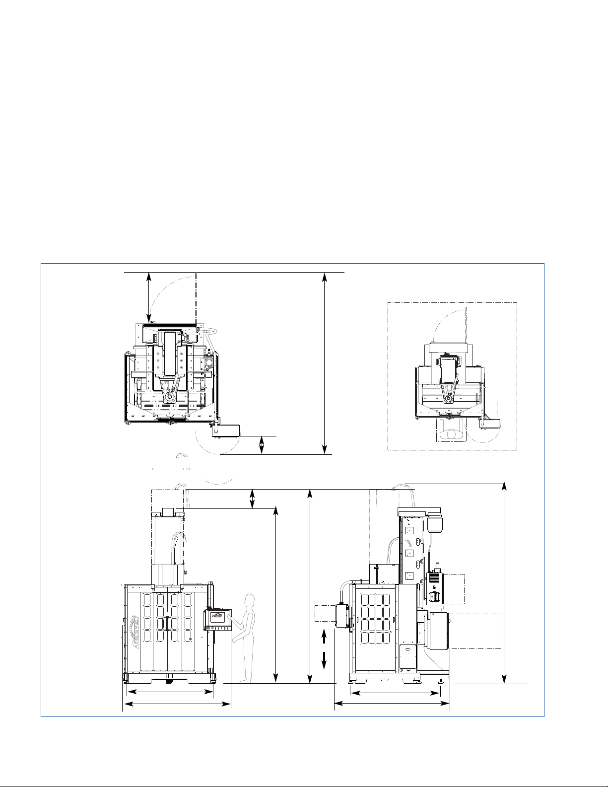
TOP VIEW
SIDE VIEW
3881 mm
(153 in.)
1200 mm
(47 in.)
1900 mm
(74.8 in.)
FIGURE 1-A, Floor Plan Layout (System Configuration)
Diameter Range (ID)1: 19 - 230 mm (0,75 - 8.0 in.)
Max. Workpiece Weight
1
: 900 kg (2000 lbs.)
Workpiece Envelope: 1016 x 1778 mm (40 x 70 in.)
Recip. (Stroke) Travel (Z Axis)
1
: Up to 1475 mm (58 in.)
Recip. (Stroke) Speed (Z Axis): Up to 168 spm; length dependent
Stroke (Column) Motor: 7,5 kW (10 hp); DC Servo
Spindle Speeds: 10 to 600 rpm
Spindle Motor: 7,5 kW (10 hp)
Feed - Rotary:
Rotary Servo Control
Sump Pump2: Centrifugal Pump
Sump Pump Motor
2
:
225 LPM @ 2m head
(68 GPM @ 6ft head)
Coolant System2: Optional
Coolant Requirements: Sunnen Industrial Honing Fluids
Control System: Industrial PC w/Windows®
Work Area
(View A)
3
: 4047 W x 4824 D x 4400 H mm
(159 x 190 x 173 in.)
Floor Space
(Machine Foot Print): 2523 W x 2563 D x4375 H mm
w/o Optional Coolant System (99 x 101 x 172in.)
Floor Weight (Dry): 5620 kg (12500 lbs.) plus Fixturing
Pneumatic Req. (Opt)
4
: 5,5 to 6,9 Bar (80 to 100 psi)
Electrical Requirements:
460V, 60Hz, 3Ph, 43A;
400V, 50Hz, 3Ph; 46A
Color: Black / Stainless Steel
Noise Emission: Less than 72 dB(A) continuous
Load (max. noise)
condition in a
typical factory environment.
1
Diameter range, length range, and workpiece weight are contingent on workpiece and application.
2
The SV-2460 does NOT come with Coolant or Pneumatic Systems. These Systems are optional and MUST be order separately.
3
Work Area includes Machine Floor Space plus clearance for operator to move around machine.
4
Base system does not require air. Air is only required for special system options.
1997 mm
(78.6 in.)
VIEW A
220 mm
(8.7 in.)
431 mm
(17 in.)
2523mm
(99in.)
2563 mm
(101 in.)
FRONT VIEW
Z
Work Area
3763 mm
(148 in.)
4101 mm
(161 in.)
4375 mm
(172 in.)
Page 7

GENERAL
Consult this section when unpacking, inspecting,
and installing Sunnen
®
Vertical Honing Machine
(see Figure 1-1). Hereafter referred to as the machine.
TOOLS & MATERIALS
The following tools and materials are required for
unpacking and installing of your Machine:
Knife Hex Wrenches
Hammer Open End Wrenches
Crow Bar Cleaning Solvent
Tin Snips Screwdriver (Std)
Slip Joint Pliers Forklift
INSTALLATION
Read the following instructions carefully and
thoroughly before unpacking, inspecting and
installing your Machine. All references to right and
left in these instructions are, unless otherwise noted,
as seen by operator as one looks at Machine or
assembly being described
(refer to Figure 1-1).
NOTE: When ordering parts for, or requesting
information about your Machine, include Model and
Serial Numbers printed on Nameplate.
1. Move Machine to staging/unpacking area.
2. Remove plastic wrap.
3. Remove top and sides from packing crate.
4. Remove all loose components from crate.
5. Check all components against packing list
6. Inspect Machine and components for dents,
scratches, or damage resulting from improper handling, by carrier. If damage is evident, immediately
file a claim with carrier.
CAUTION
Machine Base may be forked from any side. DO
NOT support weight of machine on bottom of
Electrical Enclosure when lifting or moving.
7. Remove Bolts securing Machine to Skid.
8. Using a forklift remove machine from skid and
move to desired location and lower into place
(see
Figure 1-2)
.
While machine is up in the air, screw in Four (4)
Corner Feet and Two (2) Center Feet.
NOTE: Machine should be located on a leveled
concrete floor away from heavy traffic. Allow at least
1m (38in.) around enclosure to any adjacent equipment
and walls. Refer to Figure 1-A, Floor Plan Layout.
1
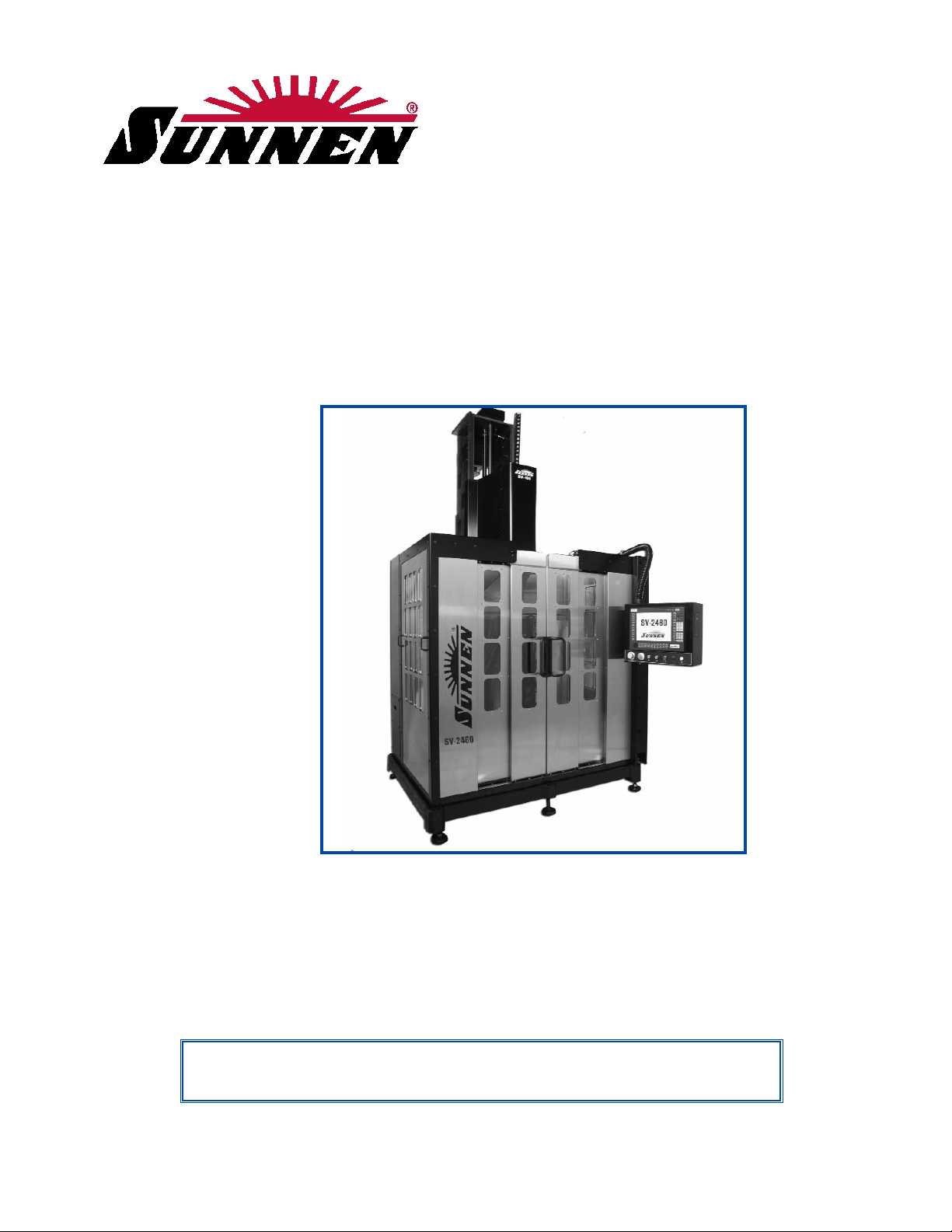
FIGURE 1-1, Vertical Honing Machine
FIGURE 1-2, Fork Lift
RIGHT
FRONT
LEFT
SECTION 1
INSTALLATION
R
S
V
3
R
SV-360
Page 8
9.
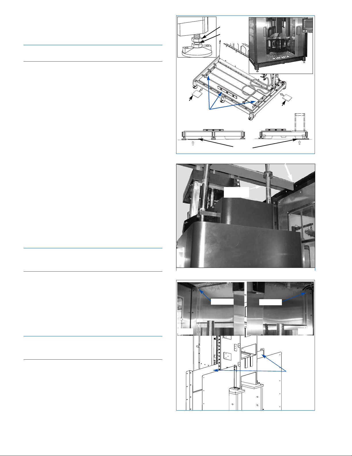
Level and stabilize Machine by placing a millwright's
level on ground Table Base (see Figure 1-3). Machine
needs to leveled both from front to back and left to
right.
NOTE: Machine does not need to be bolted to floor
but should be set on 1/2" thick steel pads.
• Begin by screwing ALL six (6) Adjustable Feet all
the way into the Table Base (until table base is resting
on the floor).
• Then check to see if any of the feet are not
touching the floor or touching the floor only
loosely. If so, bring foot down to just touch floor.
• Place Level front to back on right side of table and
adjusting Leveling Bolts in each of the right front &
rear feet as required, until table base is within
0,0003 m/m.
• Re-check and adjust any feet that are loose or not
touching, until they just touch the floor.
• Repeat for left side of table.
• Re-check and adjust any feet that are loose or not
touching, until they just touch the floor.
• Move to front of table and check front of table left
to right for level. Adjusting Leveling Bolt in which
ever of the feet is lowest as required, until table
base is within 0,0003 m/m.
• Adjust center Leveling Bolts at front of table until
it just touches the floor.
• Move to rear of table and check rear of table left
to right for level. Adjusting Leveling Bolt in which
ever of the feet is lowest as required, until table
base is within 0,0003 m/m.
NOTE: In most cases the lowest foot should be on the
same side in the rear as the one that was just adjusted
on the front of the table.
• Adjust center Leveling Bolts at rear of table until it
just touches the floor.
• Recheck table front to back and left to right.
• Tighten Jam Nuts on all the feet to lock bolts in
place.
• After leveling Table Base using by adjusting the
feet; place shims under table base wherever the base
is not in direct connect with the floor.
NOTE: This is very important. If Table Base is not
supported it may bowl when the weight of the fixture
and workpiece are installed.
10. ATTENTION - Remove steel Cross Bracket that
supports machine during shipping (see Figure 1-4).
11. Adjust Leveling Bolts as required to level
machine.
12. Remove Upper Right & Left Guarding from
inside the front of the Machine
(see Figure 1-5).
Lay Guarding and Hardware aside for reinstallation
after Column is installed.
2
FIGURE 1-4, Shipping Brackets
CROSS
BRACKET
FIGURE 1-5, Upper Left & Right Guarding
LEFT
UPPER
GUARDING
RIGHT
SCREWS
SCREWS
FIGURE 1-3, Leveling Bolts
MILLWRIGHT’S
LEVEL
JAM NUT
LEVELING
BOLT
SHIM
SHIM
SHIMS
Page 9
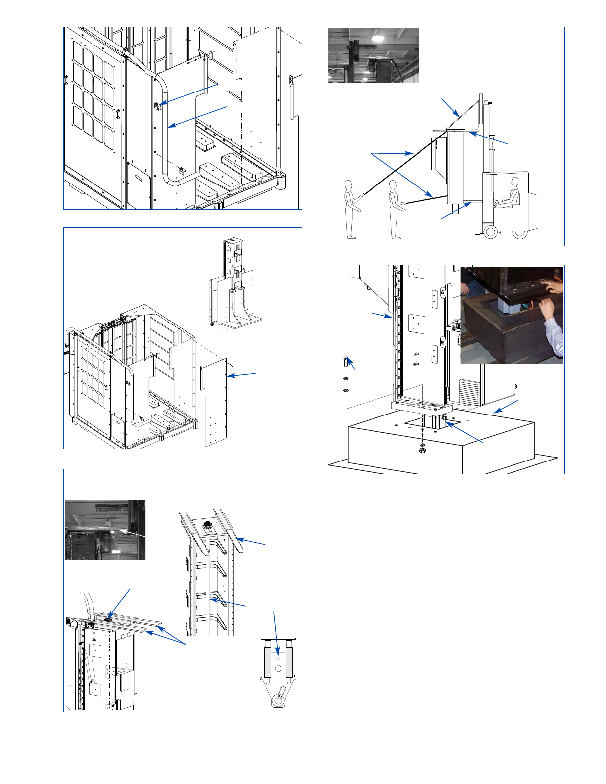
13. Remove Hardware securing Wiring Conduit to
rear of Machine and tie Wiring Conduit off to side
of Machine
(see Figure 1-6).
14. Remove two (2) Conduit Hangers from rear of
Machine
(refer to Figure 1-6). Lay Hangers and
Hardware aside for reinstallation after Column is
installed.
15. Remove Right & Left Rear Guarding rear of the
Machine
(see Figure 1-7). Lay Guarding and
Hardware aside for reinstallation after column is
installed.
Install Column
16. Obtain Fork Lift with required vertical
movement and lift capacity to lift Column into
position on Riser Weldment.
17. Position Forks so they slide into Lifting Sleeves,
provided on top of Machine.
3
FIGURE 1-6, Wiring Conduit
CONDUIT
HANGER
FIGURE 1-7, Left & Right Rear Guarding
FIGURE 1-8, Fork Positioning
FORKS
SPINDLE
ASSMBLY
GUARDING
FIGURE 1-9, Column
STRAP
BLOCK
GUIDE
LINES
FORKS
FORKS
BALLSCREW
FORKS
FIGURE 1-10, Shipping Base
SHIPPING
BASE
COLUMN
SCREW
MOTOR
Page 10
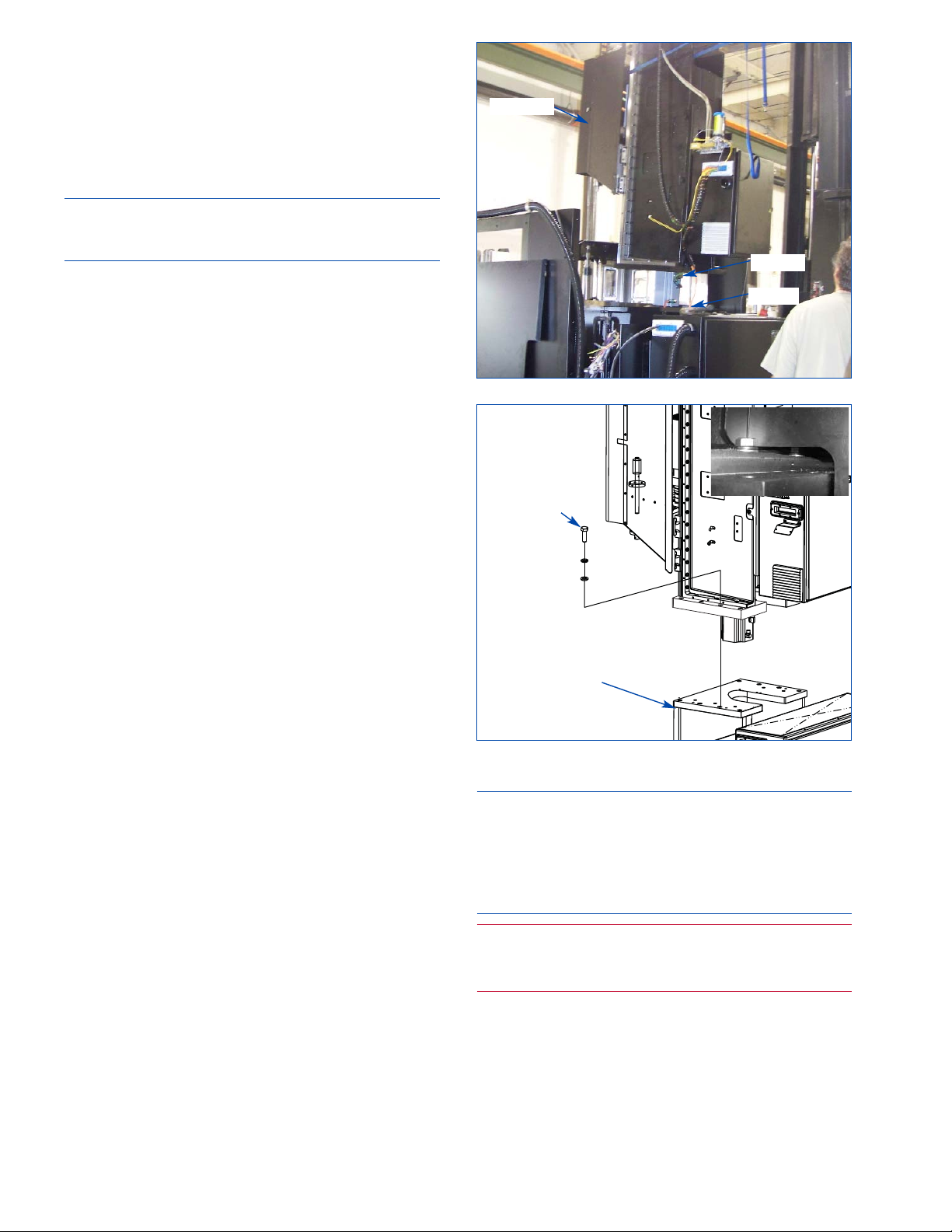
18. Raise Forks and slide into Lifting Sleeves (see
Figure 1-8)
.
19. If required: Secure top of Column to top of Fork
Lift using straps
(see Figure 1-9).
20. If required: Place a Block between the Fork Lift
and bottom of the Column to prevent the column
from swinging when it is lifted
(refer to Figure 1-9).
CAUTION
Ensure Block is not close to Ballscrew or Motor, to
prevent damage to these items while moving column.
21. If required: Secure guide straps to top and
bottom of Column.
22. Raise Forks slightly to take any slack off forks
and to be sure column is engaged. Then recheck
strapping.
23. Remove six (6) Screws attaching Column to
Shipping Base
(see Figure 1-10).
24. Carefully lift Column off Shipping Base,
ensuring Servo Motor clears shipping Base.
25. Raise Column and carefully position over Riser
Weldment. (Use Guide Straps to prevent column from
swinging or contacting Riser or Machine Guards.)
26. Slowly lower Column onto Riser, ensuring
Servo Motor clears Riser
(see Figure 1-11).
27. Align Column with Riser and secure using six
(6) Mounting Screws, Lockwashers, & Flatwashers
(see Figure 1-12).
28. Remove blocking and straps securing column to
Fork Lift. Then lower fork lift slightly and carefully
slide fork out of column.
29. Reinstall Left Rear Guarding.
30. Reinstall Right Rear Guarding and Conduit
Hangers.
31. Reposition Wiring Conduit in Hangers and
secure.
32. Install Linear Rail Cover on front of Spindle
Assembly. Two (2) Access Holes are provided on
both sides of Spindle Assembly Guarding for
attaching the Cover
(see Figure 1-13).
33. Wipe all protective shipping oil and grease from
Machine. (Clean rust preservative from way bars
and any other bright metal surfaces.)
34. If applicable: Position optional coolant system on
right side of base.
COLUMN ELECTRICAL CONNECTIONS
All wiring is to be performed by a competent,
Licensed Electrician in accordance with all local,
state, and federal codes and regulations; along with
any special information provided on machine
nameplate or electrical specification plate.
CAUTION
All wiring is to be performed by a competent,
licensed electrician in accordance with all local, state
and federal codes and regulations. FAILURE TO
COMPLY CAN RESULT IN PERSONAL INJURY
AND DAMAGE TO THE MACHINE.
WARNING
All wiring and electrical equipment service should
be performed by authorized personnel ONLY.
1. Open Door to Column Electrical Enclosure.
2. Slide wire leads through side of Enclosure and
secure Wiring Conduit by tightening Lock Ring on
Conduit Connector
(see Figure 1-14).
3. Attach numbered Wire Leads to corresponding
numbered locations inside enclosure.
4
FIGURE 1-11, Positioning Column
FIGURE 1-12, Securing Column
MOTOR
COLUMN
RISER
MOUNTING
SCREW
RISER
Page 11

MACHINE ELECTRICAL CONNECTION
All wiring is to be performed by a competent, Licensed
Electrician in accordance with all local, state, and
federal codes and regulations; along with any special
information provided on machine nameplate or
electrical specification plate
(see Figure 1-15).
CAUTION
This machine was wired for 460VAC. If it is to be
run at 400VAC the taps on the control transformer 1T
must be changed. All wiring is to be performed by a
competent, licensed electrician in accordance with
all local, state and federal codes and regulations.
FAILURE TO COMPLY CAN RESULT IN PERSONAL
INJURY AND DAMAGE TO THE MACHINE.
WARNING
All wiring and electrical equipment service should
be performed by authorized personnel ONLY.
CAUTION
Do not attempt to connect machine if supply voltage is
not within acceptable limits as noted on nameplate or
electrical specification plate. If supply voltage is not
within these limits MACHINE WILL BE DAMAGED.
Verify supply voltage is same as voltage on Machine
Nameplate or Electrical Specifications Plate.
5
FIGURE 1-13, Linear Rail Cover
SCREW
ACCESS
HOLES
COVER
FIGURE 1-14, Electrical Connections
Page 12
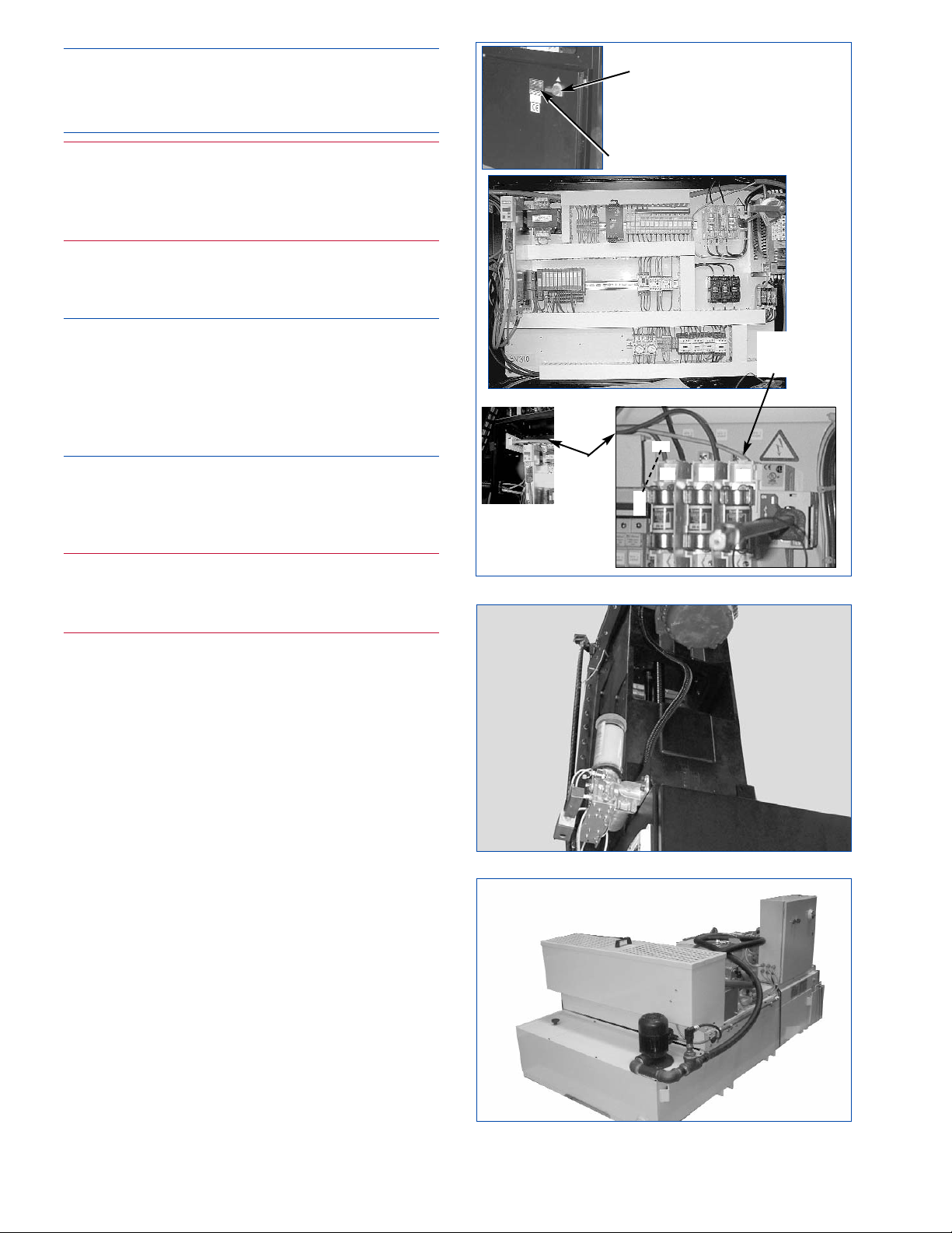
NOTE: A pre-drilled hole has been provided in
Electrical Enclosure for Electrical Supply Cord (not
supplied). Connect Cord as follows
(refer to Figure
1-15).
WARNING
Residual Voltage exists for 2-3 minutes after
Master ON/OFF Switch is turned OFF. Before
working inside Enclosure, wait for all fans to stop
running to allow drives to discharge.
1. Unlock Door to Electrical Control Enclosure.
Loosen Safety Latches on door(s) to enclosure,
using a screwdriver.
CAUTION
Door is equipped with lockable Safety Door Latch.
Door should be closed and latched during operation
to prevent accidental interruption of operation from
doors being opened. Door Latch should be LockedOut and Tagged during servicing to prevent machine
from being powered up.
2. Turn Master ON/OFF Switch to OFF position
and open Door. (Door WILL NOT open unless
Master ON/OFF Switch is in OFF position.)
3. Open Door to enclosure.
WARNING
You must use the hole provided. Drilling any new
holes in the electrical enclosure may void the
warranty.
4. Remove hole plug located on top, left side of the
enclosure. Then install an oil tight fitting.
5. Insert Electrical Supply Cord through Oil Tight
Fitting and route to Electrical Disconnect Block.
6. Strip 254 mm (10 in) off cable's outer jacket.
7. Strip 6 mm (1/4 in) of insulation off each wire.
8. Connect Green Wire (GRN) to Terminal PE on
Electrical Disconnect Switch (Earth Ground).
9. Connect other three wires to Disconnect Block
(1DISC) as noted on Block (L1, L2, L3).
10. Route and secure Cord inside of Enclosure.
11. Tighten Oil Tight Fitting.
12. Close and secure/lock Door to Enclosure.
13. Route and connect Electrical Supply Cord to
factory main power source.
14. Turn ON Master ON/OFF Switch.
LUBRICATING SYSTEM
The machine is equipped with an automatic grease
lubricating system.
6
FIGURE 1-15, Electrical Connection
NAMEPLATE
FIGURE 1-17, Coolant System (opt.)
MASTER
ON/OFF
SWITCH
L3
L1
L2
GND
GRN
ELECTRICAL
DISCONNECT
BLOCK
SUPPLY
CORD
FIGURE 1-16, Lubricating System
Page 13
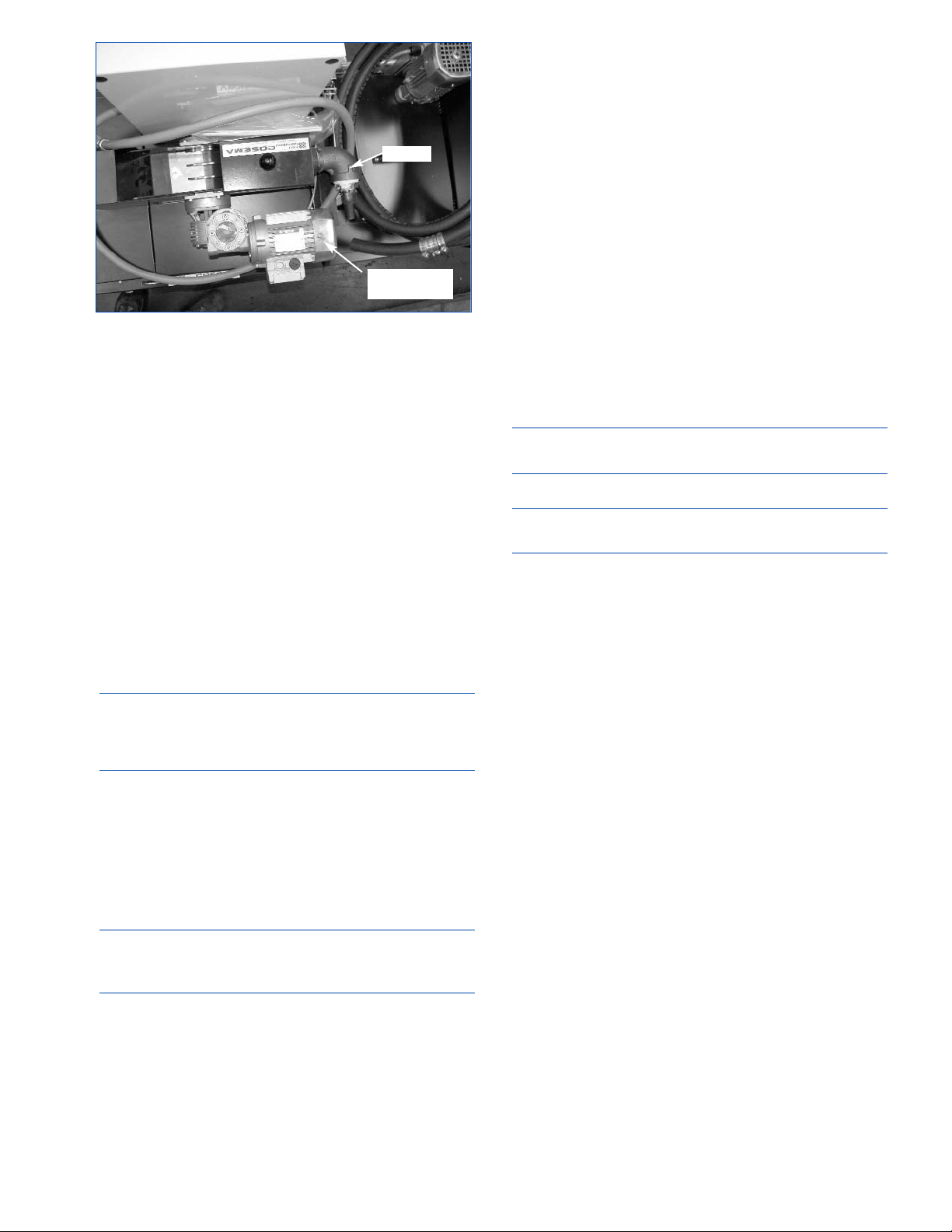
Grease Reservoir is filled at the factory with Sunnen
90123 (Kluberplex #BEM34-132 or its equivalent)
(see Figure 1-16). System is equipped with a
Pressure Switch, which flashes a warning on the
operator display screen when the level/pressure
drops below minimum requirement.
COOLANT SYSTEM (Optional)
The machine comes with a Sump Pump and a small
Reservoir. Because of the numerous application
possibilities the machine is not supplied with a coolant
system, optional Coolant Systems are available.
Placement and system requirements will vary with
coolant system used. Sunnen provides several
optional coolant systems
(see Figure 1-17). Check
with your local Sunnen Field Service Engineer or
Sunnen Products Company Technical Services for
available systems or before installing another
manufacturer's system.
IMPORTANT
Operating Instructions and Repair Parts Catalogs for
the optional Coolant Systems are supplied by the
systems manufacturer.
Fill Coolant Reservoir with either Sunnen Industrial
Honing Oil or Sunnen Water-Based Coolant.
Refer
to Section 4.
COOLANT SYSTEM CONNECTION
The machine comes with a Sump Pump and a small
Reservoir. Intake and Outlet Hose Barbs are provided for
connecting optional Coolant System
(see Figure 1-18):
CAUTION
Supply coolant pressure should not exceed 20 psi
(0,14 MPa).
MAGNETIC SEPARATOR (Optional)
Like the Coolant System, the machine is not supplied
with a magnetic separator
(see Figure 1-18). If your
application produces large amounts of metal residue, it
is recommended that you employ either or both a
magnetic separator and filter system. Check with your
local Sunnen Field Service Engineer or Sunnen
Products Company Technical Services for available
options or before installing another manufacturer's
system.
SPECIAL FIXTURE (Optional)
Because of the numerous applications possibilities the
machine is not supplied with any fixturing, optional
fixtures are available. Check with your local Sunnen
Field Service Engineer or Sunnen Products Company
Technical Services.
OPERATIONAL CHECK
Read Sections 1, 2 and 3 thoroughly and carefully
before performing the Operational Check.
NOTE: Power up and start machine to check for
proper operation.
1. Release E-STOP and press POWER ON Button.
NOTE: When machine is powered up it should open
the “Sunnen” software.
2. Once machine is through initializing, press “F1
Setup Menu.”
3. Then press “F2 Install Setup,” and follow
directions on display screen.
4. Once a setup is install; at Main Menu press “F2
Run Menu.”
5. In run settings you can toggle the coolants lines
to check the rotation of the Sump Pump Motor.
(Rotation of Shaft should be as shown on Motor
Cover.)
6. If rotation is incorrect, turn OFF power to
Machine and reverse any two wires (red, white, or
black) of electrical supply cord, where they connect
to Disconnect Block.
7. Operate Machine and check rotation of optional
equipment according to Installation Instruction
package with optional equipment.
8. Set up and test all machine functions
(refer to
Section 3)
.
9. After unpacking and installing Machine, clean
and lubricate
(refer to Section: 4, Routine
Maintenance)
.
7
FIGURE 1-18 Magnetic Separator
INTAKE
MAGNETIC
SEPARATOR
Page 14

8
NOTES
Page 15
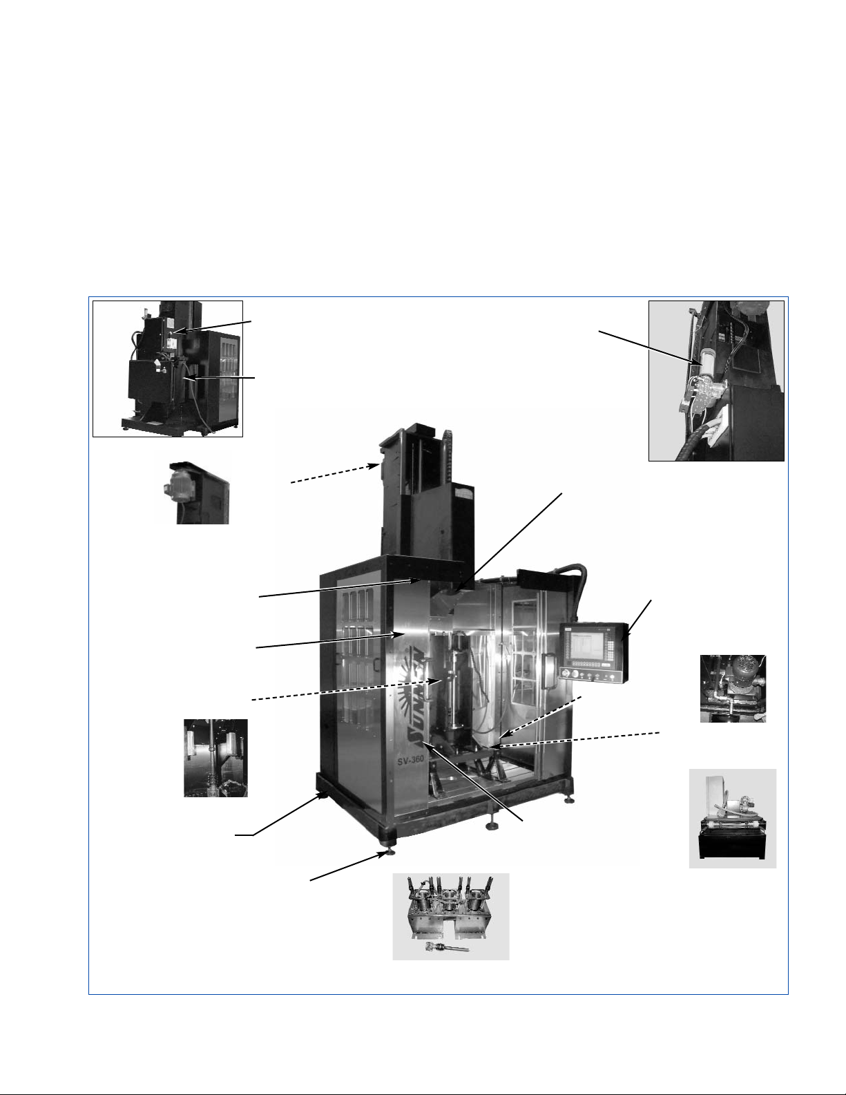
GENERAL
Consult this section when preparing the Machine for
operation.
MAJOR COMPONENTS
Consult the following figure for location of major
components on your machine,
(see Figure 2-1).
1a. The Machine Base is equipped with
1b. Leveling Bolts for stabilizing Machine and
1c. Stainless Steel Guard Doors.
2a. Electrical Enclosure. Located on rear of Machine.
2b. Column Enclosure. Located on rear of column.
3a. The Operator Station houses all electronic
hardware and software for hone control. It is also
main operator interface with machine.
4a. The Spindle Carriage is mounted on
9
FIGURE 2-1, SV-2460 Honing Machine
SECTION 2
PREPARING FOR OPERATION
- 1A -
MACHINE
BASE
- 1B -
LEVELING
BOLTS
- 4A SPINDLE
CARRIAGE
- 4E -
BALL SCREW
STROKER
ASSEMBLY
- 4B -
TRANSVERSE
ASSEMBLY
- 7A SUMP PUMP
- 4D -
DRIVE TUBE
- 3A -
OPERATOR
STATION
- 1C STAINLESS
STEEL DOORS
- 4C -
SPINDLE
MOTOR
- 8 - (OPT)
COOLANT
SYSTEM
- 5 - (OPT)
WORKHOLDING
FIXTURE
- 2B COLUMN
ENCLOSURE
- 2A ELECTRICAL
ENCLOSURE
- 9 -
LUBRICATOR
- 6 COOLANT LINES
Page 16
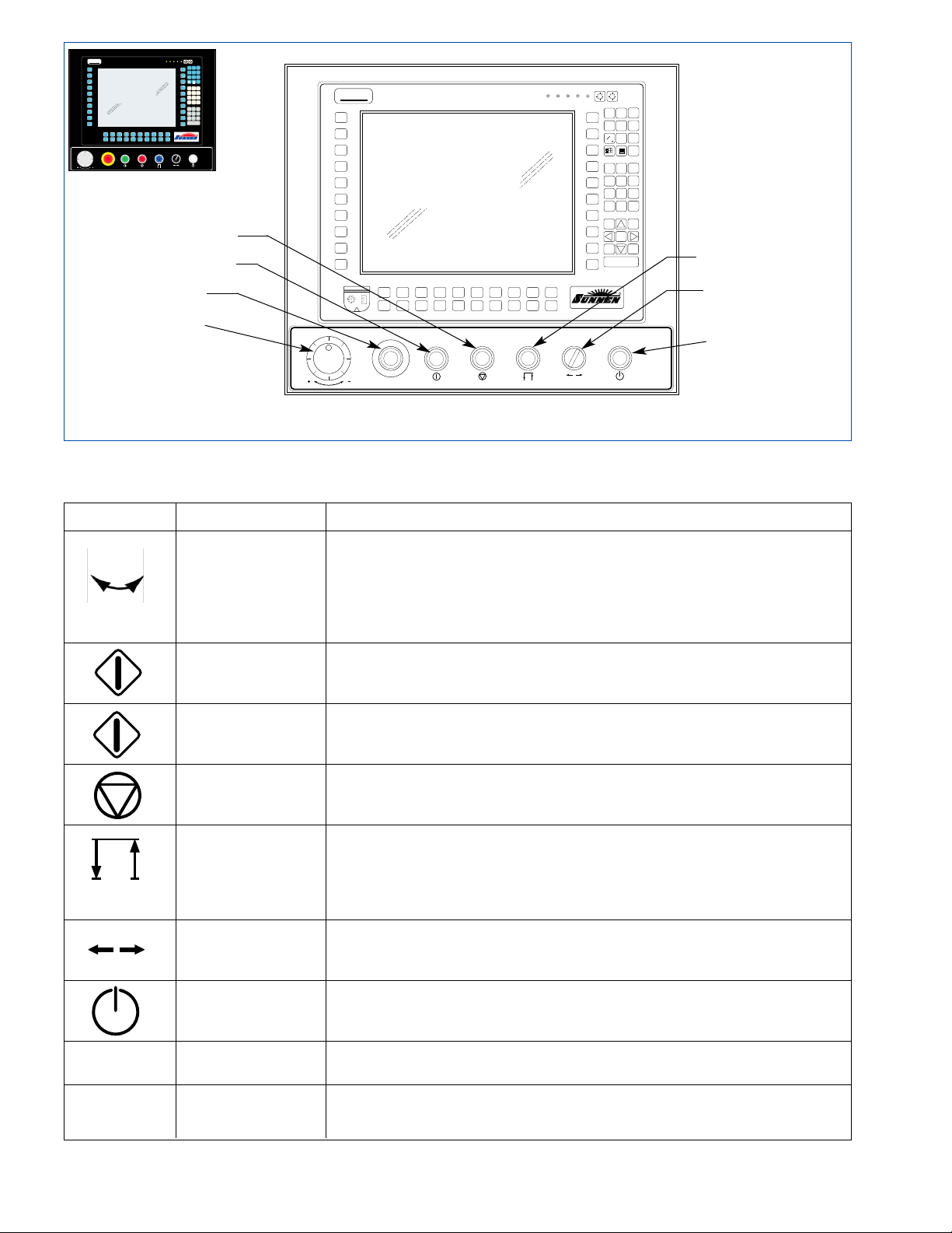
10
FIGURE 2-2, Front Panel
YCOM
R
F4F5F6
F9
F10
YCOM
x
F1
K
F11
U
F2
L
F12
V
F3
M
F13
W
N
F14
X
O
F15
Y
P
F16
Z
F7
Q
F17
:
F8
R
F18
/
S
F19
\
T
F20
.
PF8
PF1
PF2
PF3
PF4
PF5
PF6
PF7
PF9
PF10
A
B
C
E
D
G
F
I
H
J
PF18
PF11
PF12
PF13
PF14
PF15
PF16
PF17
PF19
PF20
(
)
?
%
&
@
$
>
<
-
PgUp
CTRL
ALT
F
SHIFT
TAB
SPACE
ESC
DEL
BACKSPACE
END
A
1
4
7
2
5
8
3
6
9
=
0
.
PgDn
HOME
+
-
ENTER
PgUp
PNP392A
+-
FAULTINPUTCOMDISKPOWER
R
R
SYMBOL DESCRIPTION FUNCTION
STROKER/FEED Select either Column A Stroker or Column A Feed on Operator Touch Screen.
POSITIONING
Column A Stroker - Handwheel can be used to position Tool vertically in bore (up or down).
(Handwheel)
Column A Feed - Handwheel can be used to expand or retract stones in bore.
Column A Motion -
Handwheel can be used to position carriage horizontally (left or right) on models equipped
with optional carriage servo motor.
E-STOP
Shuts-OFF all power to the machine functions. Button must release, before Power ON button
(Pushbutton, Red)
can be pushed.
CYCLE START
Switch is used start a honing cycle.
(Pushbutton, Green)
CYCLE STOP
Stops honing cycle.
(Pushbutton, Red)
DWELL
Switch is used to make stroker dwell while machine is honing. (NOTE: On Run screen, there are
(Pushbutton, Blue)
5 marks in bore profile display that represent five locations in bore. Using up and down ARROW
keys, you can move this marker to place where you would like to dwell. When you press dwell
button, stroker will dwell in location that you selected with arrow keys for 2 seconds.) For continuous
dwell, hold Dwell Button in for desired length of time.
HORIZONTAL JOG
Switch moves Stroker Carriage left or right to align tool in bore.
(Selector Switch)
POWER ON
Turns ON control power to the machine. After E-Stop Button is released; Power ON button must be
(Pushbutton, White)
pushed to turn ON Control Power.
“F” KEYS These keys are used for a variety of functions, as indicated across the bottom
of the display screen.
KEYPAD Numeric keypad is used to enter information into the display
screen.
TABLE 2-1, Operator Controls
SEC
CYCLE STOP
E-STOP
CYCLE START
STROKER/FEED
POSITIONING
HANDWHEEL
DWELL
HORIZONTAL
JOG
POWER ON
x
PF1
A
PF2
B
PF3
C
PF4
D
PF5
E
PF6
F
PF7
G
PF8
H
PF9
I
PF10
J
F1
F2
K
L
F11
F12
U
V
F5
F3
F4
F6
O
M
N
P
F15
F13
F14
F16
Y
W
X
Z
F9
F7
F8
F10
S
Q
R
T
F19
F17
F18
F20
\
:
/
.
FAULTINPUTCOMDISKPOWER
+-
ESC
CTRL
SHIFT
PF11
(
DEL
ALT
TAB
PF12
BACK-
)
F
SPACE
SPACE
A
PF13
END
?
PF14
3
1
2
&
6
PF15
4
5
%
8
7
9
PF16
$
=
0
.
PF17
@
PgUp
+
PF18
<
HOME
PF19
PgDn
-
>
ENTER
PF20
-
R
PNP392A
Page 17
4b. The Transverse Column Assembly which allows
the Spindle Carriage to move left or right to align
Spindle with bore. It is powered by
4c. the Spindle Motor which by way of a belt, drives
4d.
the Drive Tube which imparts stroking and rotational
motion from spindle to honing tool. Houses feed rod.
4e. A Ball Screw Stroker Assembly located inside of
Column provides stroking power to Spindle Carriage.
5. Workholding Fixture (opt)
6. The Adjustable Coolant Lines allows manual
regulation of honing fluid flow through the
7a. The Sump Pump pumps coolant from the
machine base reservoir.
7b. A Coolant Interface allows an optional coolant
system to be attached to the machine.
8. A Coolant System (opt) can be added to ensure
debris is removed from coolant.
9. An automatic Lubricator provides grease to the
major components of the machine.
OPERATOR CONTROLS
For the location and function of the operator
controls
refer to Figure 2-2 and Table 2-1.
SAFETY SYMBOLS
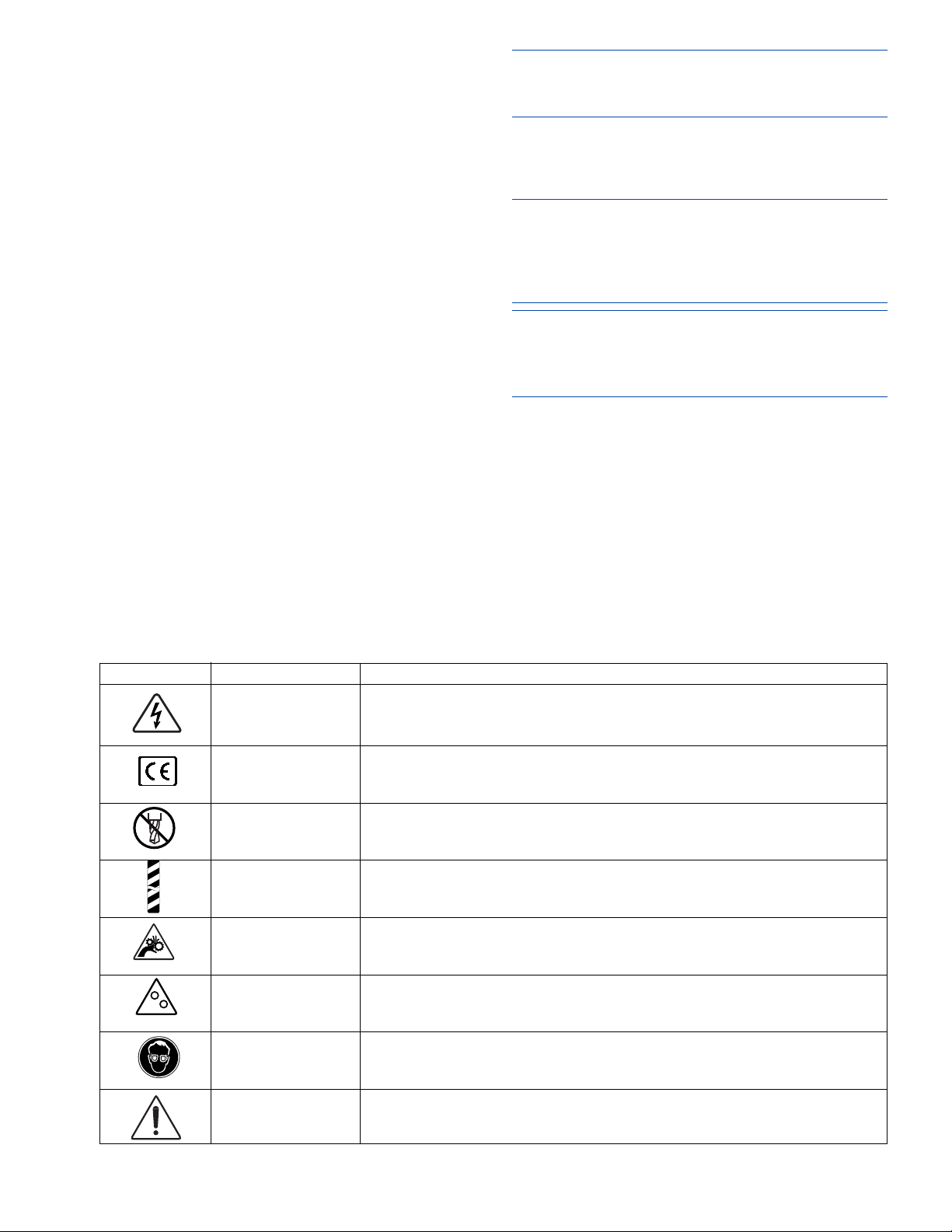
For a description of safety symbols used on this
machine,
refer to Table 2-2.
WORKHOLDING FIXTURE
Install and align Optional Workholding Fixtures
according to instructions packaged with fixtures
supplied for your particular application.
NOTE: Fixtures used on these machines are custom
made for each job. Follow installation and alignment
procedures packaged with your fixture.
HONING TOOL
Refer to Sunnen Industrial or Automotive Honing
Supplies Catalogs for all your honing needs
CAUTION
Use of tooling other than Sunnen tooling will render
all of features of computerized honing system
useless, due to fact that machine and all its
parameters are calibrated to Sunnen Tooling only.
NOTE: On SETUP screen, there is a TOOL option.
This option allows operator to select type of tool that
will be used. The correct tool family needs to be
selected in order for feed system to operate properly
Sunnen offers a wide verity of tooling options within
the diameter range of this machine. Including:
CK/CV-Series Hone Heads 51-203mm
GHSS/GHTS-Series Hone Heads 38-141mm
The following options require a mandrel adapter:
P20/28-Series Hone Heads 19-152mm
MPS-Series Hone Heads 50-216mm
PH-Series Hone Heads 50-203mm
(with in-process air gaging)
11
SYMBOL DESCRIPTION FUNCTION
Warning Label Warns that an
electrical hazard
exists.
Label Designates this machine is
“CE” compliance
.
Warning Label Warns that no drilling is allowed. Drilling any new holes may void warranty.
Warning Strip Warns that a
physical hazard exits
, and that proper precautions should be taken.
Caution Label Warns that a finger hazard exists. Do not touch while
Moving Parts stroker is operating.
Warning Label Warns that power must be OFF when belt guard is opened,
(Light) to prevent injury.
Warning Label Warns that safety glasses should be worn at all times when
(Safety Glasses) operating this machine.
Warning Label General Warning.
TABLE 2-2, Safety Symbols
Page 18
HONING TOOL SETUP
When using CK/CV or GHSS/GHTS Series Hone
Heads proceed to, Installing Hone Head.
When using P20/P28 Mandrel and CV1010 Mandrel
Adapter, proceed with the following steps:
P20/P28 Mandrel & Mandrel Adapter
Following is a setup guide using mandrel adapter.
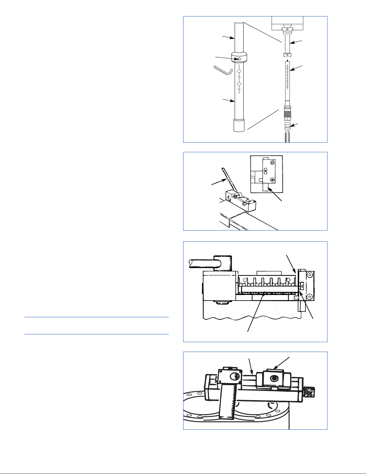
1. Using an adjustable wrench, turn feed rod in
Mandrel Adapter counterclockwise until wedge hook in
adapter nose is fully extended.
2. Slide drive tube end of Mandrel Adapter into drive
tube of machine, and tighten set screw into one of
holes
(see Figure 2-3).
3. Rotate mandrel adapter by hand until its set screw
points toward you.
4. Insert stones into mandrel.
5. Pull back on mandrel wedge, using "V" notch in
chuck wrench.
6. If required, place concentric sleeve on mandrel. If
runout is excessive during honing, replace sleeve with
eccentric sleeve. If runout remains excessive, turn
sleeve around.
7. Insert mandrel into adapter.
For all "P" series mandrels under 66 mm (2.6 in.),
stones should be 90º to right of set screw.
For all "P" mandrels over 66 mm (2.6 in.), stones
should be 90º to left of set screw.
8. Push mandrel up into Adapter until it bottoms, rotate
it 1/4 turn to right, and push up until it bottoms again.
9. Tighten Set Screw securely with chuck wrench.
CV/CK-Series Hone Heads
Install CV/CK-Series Hone Head by sliding Hone
Head Drive Tube into Machine Drive Tube; align
Locating Screw in Hone Head Drive Tube with one of
holes Machine Drive Tube; then, tighten screw
(refer to
Figure 2-3)
.
NOTE: Locating Screw can be screwed into hole in
lower part of Drive Tube when index lines are in line.
Replacing Stones
To replace stones in CV/CK-Series Hone Head,
proceed as follows:
1. Slide Movable Stop to OUT position. Insert Stone
Assembly with worn-out stone into fixture and pull
lever toward you until stone is free from master
stoneholder.
2. Brush chips and grit from Master Stoneholder slots.
3. Move Lever to open position and slide Movable
Stop to IN position
(see Figure 2-4). Fixture is now
ready for inserting new stone.
12
FIGURE 2-3, Install Mandrel Adapter
DRIVE
TUBE
FIGURE 2-4, Open Position
MOVABLE
STOP
INSERTER
LEVER
FIGURE 2-5, Install Stone
STONE
NOTE STONE
AGAINST STOP
STOP
FIGURE 2-6, Setting Gage
OPENING
TURRET
BLOCK
DRIVE
TUBE
MANDREL
ADAPTER
MANDREL
ADAPTER
MANDREL
SETSCREW
Page 19
4. Place Master Stoneholder in fixture. Brush all loose
chips from Stoneholder grooves and slots.
5. Place Stone in Master Stoneholder
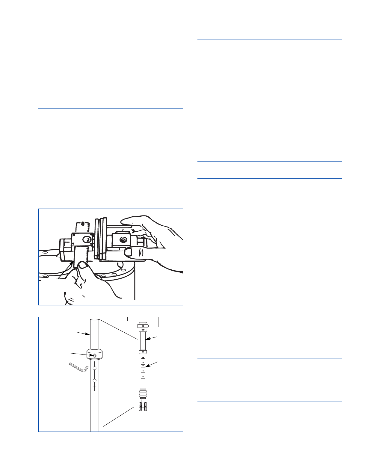
(see Figure 2-5).
Lugs on stone sides should fit into cross slots of Master
Stoneholder.
6. Seat Stone in Master Stoneholder by pressing down
with fingers. Pull lever forward until Stoneholder hits
stop. Stone is now in place.
Install Guide/Stone Shims
7. Place Setting Gage in bore to be honed; then snug,
making sure to center (see Figure 2-6).
NOTE: On CK-3155 Setting Gage, make sure proper
side of Turret faces Opening. (Gage faces are labeled for
tool Choices.)
8. Place Guide/Stone Assembly in Setting Gage with
graduated slide set at "0"
(see Figure 2-7).
9. Move graduated slide so that pin contacts guide. If
pin does not contact guide, add a No. 19 shim and try
again. Now add necessary shims as indicated on slide.
Looseness less than thickness of one shim is acceptable.
Special instructions for using CK-4155 Setting Gage
for large hone head in 102-203 mm (4-8 in.) range:
Move graduated slide so that pin contacts assembly.
If graduated slide reads "15" or less, no additional
shims should be added; if slide reads over "15",
remove assembly from Gage and add one shim.
NOTE: A properly shimmed assembly will slip into
gage easily. Both Guide/Stone Assemblies must have
same thickness of shims, and each must fit in Setting
Gage when assembled with shims.
10. Rotate Drive Tube until numeral "1" appears on
Hone Body. Insert one stone assembly with shims in
left-hand set of holes beneath numeral.
11. Insert other shimmed Stone Assembly beneath
numeral "2", using procedure above.
12. Insert shimmed Main Guide beneath numeral "3"
on Hone Body.
13. Place shimmed Centering Guide beneath numeral
"4" on Hone Body.
Alignment Guide
NOTE: DO NOT use alignment guides when honing
ported or keyway bores.
14. Place Alignment Guide in setting gage with
graduated slide set at "0". Loosen Clamp Screw on
alignment guide with hex key wrench and slide to
Shoulder. Tighten Clamp and repeat procedure with
second alignment guide.
15. Place one of alignment guides in left-hand set of
holes above numeral "1" in hone body, so guide and
stone are in line.
16. Place other alignment guide in left-hand set of
holes above numeral "2" in hone body, so guide and
stone are also in line.
GHSS-Series Hone Heads
Sunnen GHSS-Series Single Stage Honing Tools
consists of four sets of six (6) to eight (8) spring
loaded stoneholders, which utilize Sunnen abrasives.
Install GH-Series Hone Head by sliding Hone Head
Drive Tube into Machine Drive Tube; align Locating
Screw in Hone Head Drive Tube with one of the holes
in the Machine Drive Tube; then, tighten screw
(see
Figure 2-8)
.
NOTE: Locating Screw can be screwed into hole in
lower part of Drive Tube when index lines are in line.
Install Abrasives:
NOTE: Hone head and tops of stoneholders are marked
with corresponding numbers, as are the expander plates. All
numbered pieces should be kept together when using this
tooling.
Grasp stoneholder in one hand (i.e., GHG14C233-7)
and abrasive in the other hand. Lay abrasive in holder
with slot in abrasive facing away from holder
(see
Figure 2-9)
. Center the abrasive in holder. Using a
5/32" allen wrench, tighten allen head Screw in holder
13
FIGURE 2-7, Main & Centering Guides
GRADUATED
SLIDE
FIGURE 2-8, GHSS Hone Head
DRIVE
TUBE
DRIVE
TUBE
GHSS
HONE
HEAD
SETSCREW
Page 20
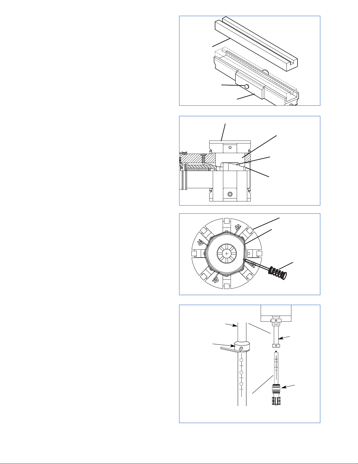
snugly. Take mounted stoneholder in one hand; look
at it lengthwise from one end, into a light to see if
there is any light between stoneholder and bottom of
abrasive. The abrasive should sit completely flat in
the holder.
Install Stoneholders and Expander Plates
Always install stoneholders and expander plates in sets.
To install, proceed as follows:
1. Verify the hone head is fully retracted.
2. It is easiest to put two holders and plates into the
head at a time, working in a counterclockwise
direction, looking down from the universal joint
(see Figures 2-10 & 2-11).
• Align angles on expander plate to corresponding
angles on cone inside of the tool.
• Insert two numbered expander plates and load
stoneholders into slots, keeping number on top of
holder and plate to the left.
• Grab the bottom of spring of one of the holder and
pull it over spring slots in bottom of holder, using
the Thumb Spring Tool
(refer to Figure 2-11).
Repeat for second holder.
• Then, go to top of hone head and pull springs over
spring slots in top of holder.
3. Proceed to next two expander plates and
stoneholders and
repeat step 2 until the hone head is
loaded with plates and holders.
4. Once all plates and holders are loaded in head,
expand and retract holders in head several times to
ensure all moving parts are seated in head properly.
Remove Stone Holders
When removing stone holders, always remove in
pairs. To remove and/or replace holders, proceed as
follows
(refer to Figure 2-11):
1. Grab spring on bottom of head in between mounted
clips and pull it down and away from bottom of
holder, using thumb spring tool (GH-50). Repeat for
second holder.
2. Then, go to top of hone head and pull springs
off of the same two holders.
3. Pull the holders out of hone head making sure
expander plates stay in the hone head.
4. Fill the empty slots in hone head with new stone
holders, and reattach springs.
5. Proceed to next two stone holders and repeat steps.
Truing Stones
Sunnen diamond abrasive honing stones have been
pre-ground to a radius and can be used directly from
the box. Bore geometry should be monitored as the
stones true in.
14
FIGURE 2-10, Install Expander Plates
FIGURE 2-9, Install Stones
STONEHOLDER
FIGURE 2-11, Install Holders
THUMB
SPRING
TOOL
STONES
SPRING
SCREW
ABRASIVE
FIGURE 2-12, GHTS Hone Head
DRIVE
TUBE
DRIVE
TUBE
GHTS
HONE
HEAD
SETSCREW
PLATES
ANGLE
STONE
CONE
Page 21
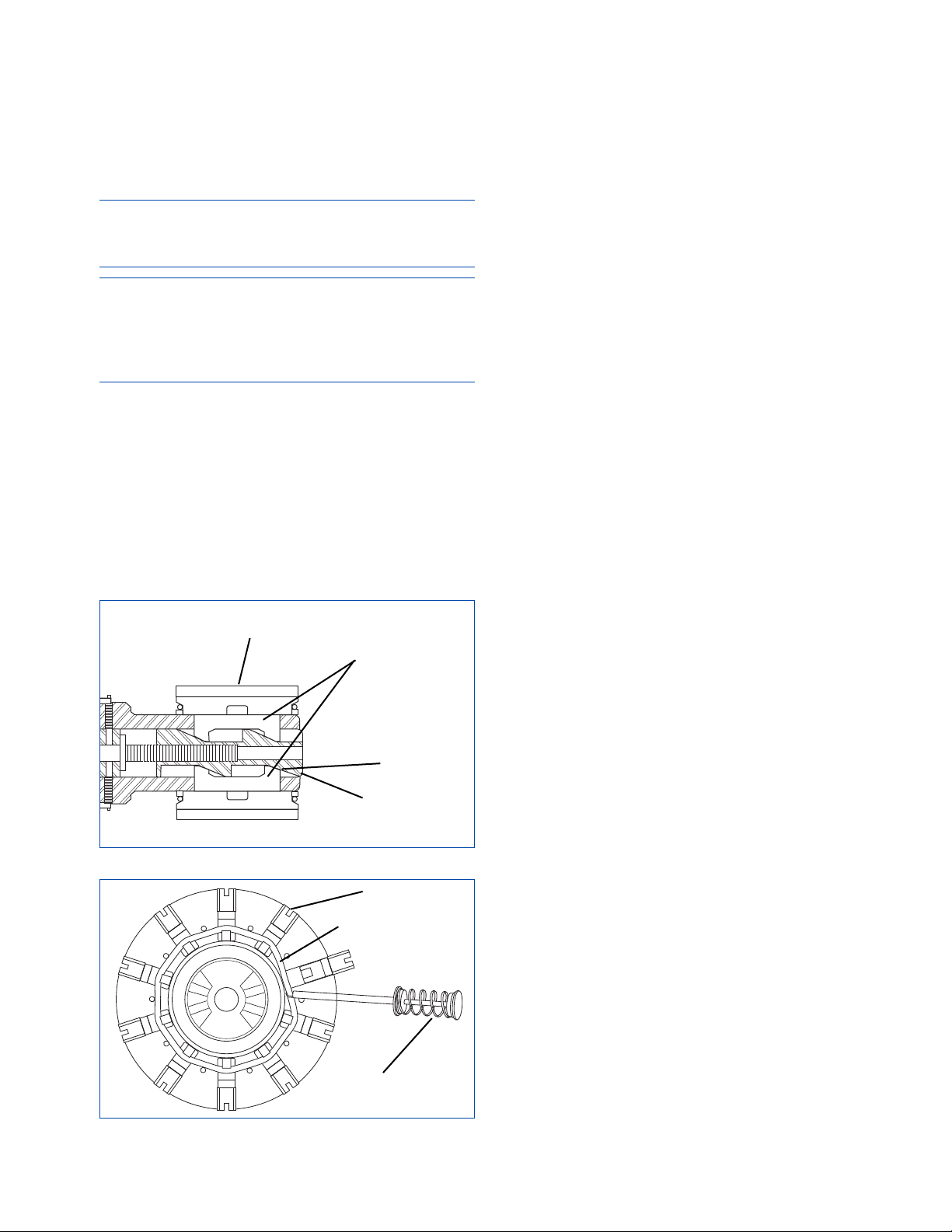
GHTS-Series Hone Heads
Sunnen GHTS-Series Two Stage Honing Tool uses
Sunnen GH Stone Sets and PHT Brush Sets.
Install GH-Series Hone Head by sliding Hone Head
Drive Tube into Machine Drive Tube; align Locating
Screw in Hone Head Drive Tube with one of the holes
in the Machine Drive Tube; then, tighten screw
(see
Figure 2-12)
.
NOTE: Hone head and expander plates are marked
with corresponding numbers. All numbered pieces
should be kept together when using this tooling.
IMPORTANT
Note reference mark on end of cone and on hone
body. These marks MUST be aligned to ensure cone
will be matched to expander plates. DO NOT deviate
from this orientation.
Install Expander Plates
Before installing stone/brush sets, check to make
sure expander plates are in their correct locations
(see Figure 2-13). Each plate is marked with a
number and a letter, which corresponds to mating slot
on hone body. Expander plates are angle cut; plates
must be installed to match angles of inner cone.
Install Stone/Brush Sets
Always install stones/brushes in as sets. To install,
proceed as follows:
1. Verify hone head is fully retracted. Both sets of
expander plates should be flush against the hone
body once inserted into their correct numbered slot.
2. It is easiest to put grouping of stone/brush sets
into head at a time, working in a counterclockwise
direction, looking down from universal joint
(see
Figure 2-14)
.
• Grab spring on bottom of hone head, in between
mounting clips, and pull it over spring slots in
bottom of stone/brush set, using GH-50 Thumb
Spring Tool
(refer to Figure 2-14). Repeat for second
set.
• Then, go to top of hone head and pull springs over
spring slots in top of stone/brush sets.
3. Proceed to next stone/brush sets and
repeat step 2
until hone head is loaded with all stone/brush sets.
4. Once all stone/brush sets are loaded in head,
expand and retract sets in head several times to
ensure all moving parts are seated in head properly.
Remove Stone/Brush Sets
When removing stone/brush sets, always remove in
sets. To remove and/or replace stone/brush sets,
proceed as follows
(refer to Figure 2-14):
1. Grab spring on bottom of hone head, in between
mounted clips and pull it down and away from
spring slots in bottom of stone/brush set, using GH-50
Thumb Spring Tool. Repeat for second set.
2. Then, go to top of hone head and pull springs off
spring slots in top of same two stone/brush sets.
3. Pull stone/brush sets out of hone head making
sure expander plates stay in hone head.
4. Fill empty slots in hone head with new
stone/brush sets, and reattach springs.
5. Proceed to next two stone/brush sets and repeat
steps.
Truing Stones
Sunnen diamond abrasive honing stones have been
pre-ground to a radius and can be used directly from
the box. Bore geometry should be monitored as the
stones true in.
15
FIGURE 2-13, Install Expander Plates
PLATES
ANGLE
STONE/BRUSH
CONE
FIGURE 2-14, Install Holders
THUMB
SPRING
TOOL
STONES
SPRING
Page 22

16
NOTES
Page 23
GENERAL
This section gives step-by-step setup and operating
procedures for Sunnen
®
Vertical Honing Machine.
SAFETY PRECAUTIONS
The following precautions should be observed to
ensure maximum safety while working on or around
your Machine.
• Wear proper Safety Items (such as safety glasses
and other personal safety equipment as necessary or
required).
• DO NOT wear loose fitting clothes or jewelry
while working on or around Machine.
• Keep area around Machine free of paper, oil,
water and other debris at all times.
• Keep Machine and area around machine cleaned
of excessive lubricant and lubricant spills.
• Keep tools and other foreign objects clear of
Machine while in operation.
• Keep tools clean and in their proper storage
compartments to maintain them in proper working
condition and to prolong tool life.
• Inspect Tools before using. Check for cracks, burrs
or bent parts that might effect operation.
• DO NOT force tools when operating. Tools will
do a better and safer job when operated at the rate
for which they were designed.
• Turn OFF electrical power when performing service
on your machine, which does not require power.
• Disconnect Machine from main power supply and
allow drives to drain before any work is performed
inside of Electrical Enclosure.
• Ensure all Guards are in place and are in proper
working order.
• DO NOT override safety switches or lockouts.
Where interlocking systems rely on special
actuators or keys, DO NOT keep spare/master
actuators or keys on, around or near machine.
• Use proper lifting procedures when loading and
unloading the Machine.
• Keep all non-essential persons clear of work area.
Visitors, especially children, should not be permitted
near the work area.
• DO NOT use machine for other than its intended
use. Using these Machines for other purposes could
result in damage to machine and loss of warranty.
• Be sure to work in a well lit area and to use light
supplied to avoid dangerous unseen conditions
which may exist otherwise.
• Use ONLY factory authorized or recommended parts
or replacement accessories. Using parts or accessories
other than those approved by Sunnen could result in
damage to machine and loss of warranty.
• Electrostatic discharge can damage the circuitry of the
electronic components used in this Machine. Use proper
electrostatic controls when working with or around
electronic components. Ground Machine and use wrist
strap to reduce the chances of static discharge.
• Residual Voltage exists for 2-3 minutes after
Master ON/OFF Switch is turned OFF. Before
working inside Enclosure, wait for all fans to stop
running to allow drives to drain.
OPERATING TIPS
If load meter is indicating loads of over 95% consistently,
reduce spindle speed. If lowest speed is being used,
increase feed rate to break down stone, or use a softer
stone. Also verify that “Rapid Until Load” is set
correctly by reviewing Load graph and observing
trend. Remember, if starting load is higher than steady
state operating load, result is stone wear without
corresponding stock removal.
If honing technique above does not result in greater
stone life, use a lower feed rate setting.
If a low operating load accompanies poor stone life,
increase spindle speed or use a harder grade stone.
If stock removal rates are too low:
Increase stroking rate.
Use a higher feed rate.
Use a coarser stone.
Use a harder stone.
If bore is tapered, remove taper by using the dwell
feature activated by pushing BLUE dwell button. You
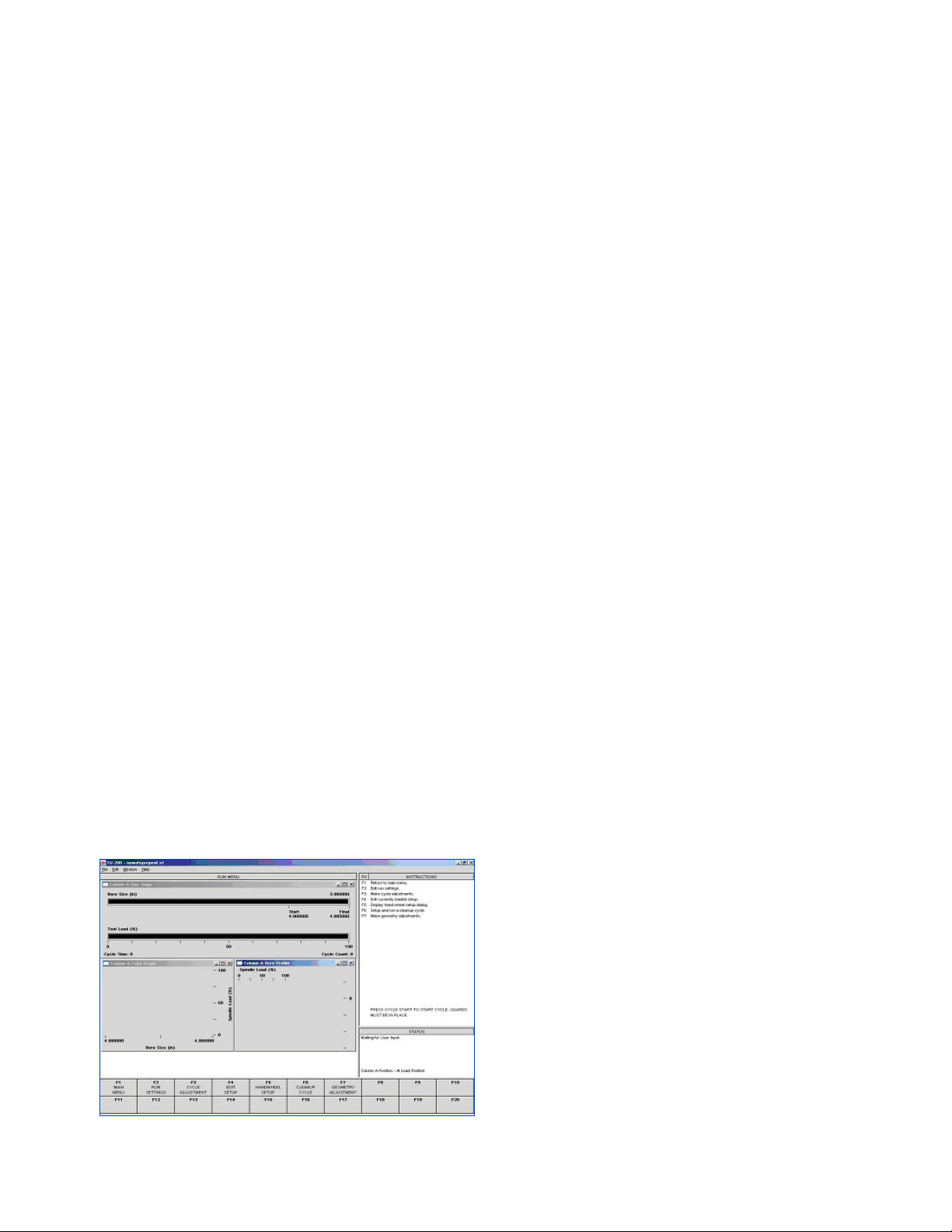
can push this button while machine is honing. On RUN
screen (inside Bore Profile), there are five marks in
middle of screen that represent five locations in bore
17
SECTION 3
SETUP & OPERATION
FIGURE 3-1, Run Screen
Page 24

(see Figure 3-1). Using up and down ARROW keys,
you can move this marker to a place in bore that you
would like to dwell. When you press dwell button,
stroker will dwell for two seconds in location that you
selected with arrow keys. This button can be held in to
make machine dwell longer.
Tool with Mandrel Adapter
1. If workpiece gets barreled or bellmouthed during
honing, first try making adjustments
, located in Run
Menu, F7-Geometry Adjustments.
2. If workpiece gets bellmouthed during honing,
shorten stone only; do not shorten shoe. If workpiece
gets barrel shaped during honing, shorten shoe only; do
not shorten stone.
CV/CK-Series Hone Heads
1. If workpiece gets barreled or bellmouthed during
honing, first try making adjustments
, located in Run
Menu, F7-Geometry Adjustments.
If hole is bellmouthed, shorten stroke. If hole is barrel
shaped, lengthen stroke. If stone becomes tapered,
check alignment guides for proper setting. Also check
Main guide #3 for taper. If guide is tapered, shorten
guide on thick end and place #1 stone in #2 position
and vice-versa.
GH-Series Hone Heads
1. If workpiece gets barreled or bellmouthed during
honing, first try making adjustments
, located in Run
Menu, F7-Geometry Adjustments.
2.
If hole is bellmouthed, shorten stroke. If hole is
barrel shaped, lengthen stroke.
Extra Fine Stones
Finishing stones, 280 grit and finer, are available for
applications where a finer finish is required. When
these fine grit stones use a conventional or vitrified
bond, there is a delicate balance between glazing,
which is caused by insufficient stone pressure, and
stone crumbling, which is caused by excessive feed
rates.
The SV-Series has several features to aid in finding this
balance and maintaining consistent honing performance.
First of these is “Rapid Until Load” feature, which is
found in the setup screen under Feed Prehone
, this is
located in Run Menu, F4-Edit Setup, F5-Column A
Setup
. This is percentage of spindle's full load that
machine waits to see, before machine stops Rapid
advancing and starts to use programmed feed rate.
Another feature is Load Meter and its display
characteristics. There are three displays that are
available to operator. First is BORE PROFILE. This
display shows a picture of load vs. stroke position
through bore. In most cases it will display condition of
bore (i.e., taper, barrel, or bellmouth) during cycle.
Second type of display is BAR GRAPH. This display
shows a bar graph of machine load as cycle progresses.
Last display is LOAD GRAPH. This display will show
machine load vs. time. Last display will help in
optimizing Rapid Until Load (RUL) value. If you use
load graph to determine RUL, ideal condition is to
have trend of graph be horizontal. If trend is upward,
RUL is too low. If trend is downward, RUL is too high.
SETUP - INITIAL
To set up your machine for operation select "F1Setup Menu" from Main Menu then select “F2-New
Setup.” The machine's operating system software
will walk you through the setup procedure step by
step on the display screen. Follow all instructions
carefully.
Special Topics
Controls: See Section 2, Operator Controls
Select & install Tools: See separate instructions
package with tool.
Tool Runout: See separate instructions package
with tool.
Fixture Setup: See separate instructions package
with fixtures
Tool & Fixture Alignment: See separate instructions
package with fixtures
In preparation for going through the setup sequence,
the following preliminary steps can be helpful:
• Install and align any fixturing.
SETUP & OPERATION
Consult the following procedure when setting up
your machine for operation. (Machine's control
software will walk you through the setup procedure
step-by-step on the view screen. Follow all
instructions carefully.)
1. Install Workpiece.
2. Release E-stop by turning clockwise and follow
instructions on right side of display screen.
3. Press Power ON (white) button. (Drives
parameters are being verified.)
4. When instructed, press Cycle Start (green )
button.
• Once Run Menu display screen appears, press F1-
Main Menu.
• Once Main Menu display screen appears, press
F1-Setup Menu.
5. Then press F2-New Setup. (A window will pop
open telling you “current setup will be cleared.” )
• Press YES to proceed.
6. Follow directions on display screen for entering
a new setup:
• Key in desired value using key pad - Press OK to
accept.
START DIAMETER: 3.490000
• Key in desired value using key pad - Press OK to
accept.
FINAL DIAMETER: 3.675000
18
Page 25

• Key in desired value using key pad - Press OK to
accept.
BORE LENGTH: 3.50000
• Select Material - Press OK to accept.
MATERIAL: Tool Steel
• Select Hardness - Press OK to accept.
HARDNESS: 2
7. Press NEXT to continue with setup: (Follow
directions on display screen.)
• Select Tool Family – This will display your tool
selection options. (Select tool family.)
CV
• Select Tool.
CV-3305A (CK-3035A)
8. Press NEXT to continue with setup: (Follow
directions on display screen.)
• Under Honing Options click in the boxes to
activate Pre & Post Hone Spindle Rotation. This
will activate grayed out buttons to the left.
• Honing Parameters are calculated based on pre-
programmed information. Only change these values
if necessary.
NOTE: To Change: Click on parameter you wish to
change, key in value, and press OK.
9. Press NEXT to continue with setup: (Follow
directions on display screen.)
• Under Feed Options clicking in the box will
activate Rapid Until Load button to the left and gray
out Amount Before Start button.
• Pre-Honing Feed Parameters are calculated based
on pre-programmed information. Only change these
values if necessary.
10. Press NEXT to continue with setup: (Follow
directions on display screen.)
•
Select Honing Feed Rate 1, key in 0.02, and press OK.
• Leave Feed Options alone at this time.
11. Press NEXT to continue with setup: (Follow
directions on display screen.)
• Under Feed Options click in boxes for Sizing and
Sparkout. This will activate the related buttons to
the left.
• Leave Crosshatch Options alone at this time.
12. Press NEXT and select install new tool.
13. Press NEXT and follow directions on display
screen.
14. Once Tool is installed press NEXT and then
press YES on the window that says “Teach Tool
Size (Snug).
15. Set tool SNUG diameter by moving tool around
in bore, while using handwheel, expand tool (CW)
or retract tool (CCW), until tool feels snug in bore.
16. Press TEACH to set Snug Diameter. Box to
right will turn green and display “the snug size is
set.”
17. Press NEXT and continue to follow directions
on display screen for setting stroke.
18. Under Loading Method select Manual.
19. Press FINISH when stroke is set.
20. Press Yes to save setup.
21. Select location to save file. Name the File. Then
Press Save.
22. Press F10 to access Run Menu.
23. Install workpiece in fixture.
24. Press F2, Run Settings.
25. Click on Machine Tab.
26. Toggle ON Coolant (Green).
27. Under Cycle Mode click Single.
28. Press APPLY and then press OK.
29. Close all Guards.
30. Press CYCLE START button and run a honing
cycle.
31. Open Guards.
32. Remove and check (gage) workpiece(s).
• To edit: Press F4 Edit Setup. Then press F4 to edit
Part Specifications or F5 to edit Column A Setup
(Machine).
33. Press OK when finished.
34. Press F10 to return to Run Menu.
35. Load parts.
36. Continue Honing.
SAFE SHUTDOWN
(Turning Machine Off)
To turn OFF the Machine properly, DO NOT just turn
off the disconnect switch. Please follow the following
steps:
1. Using the Mouse, left click on the ⌧ that is located
in the upper right corner of the screen.
2. This will display the exit password dialog box. Enter
“shutdown” (all lower case) and then click on he OK
button.
3. After a few moments, a dialog box will come up
on the screen saying that it is safe to turn off the
computer. At this time, you can turn off the
disconnect switch
.
19
Page 26

20
NOTES
Page 27
GENERAL
The following procedures are given as guides only
and are not to be construed as absolute or invariable.
Each machine must be maintained individually
according to its particular requirements.
WARNING
ALWAYS have power OFF when doors are open
or performing service not requiring power.
CLEANING
Daily, after use, wipe exterior of the Machine with a
clean, dry cloth to remove any coolant, dust and
grime. Empty Pail (Magnetic Separator) as required.
Monthly, wipe with a clean dry cloth. Then clean
the exterior of Machine with warm water and a mild
detergent or mild industrial solvent. Rinse
thoroughly with clean hot water and wipe dry.
Lightly lubricate following lubrication instructions.
LUBRICATION
Inspect Grease Lines and Fittings monthly for leaks
or damaged parts. Replace parts as required.
CAUTION
ALWAYS fill grease canister using filling port.
Ensure no air is inside grease canister.
Grease Lubricating System
Fill Grease Reservoir with Sunnen 90123
(Kluberplex #BEM34-132 or its equivalent)
(see
Figure 4-1)
.
Fill grease reservoir through grease fitting with
grease gun equipped with air relief valve. It is
important to the operation of the grease pump that
no air is in the grease reservoir. System is equipped
with a Pressure Switch, which flashes a warning on
the operator display screen when the level/pressure
drops below minimum requirement. To bleed system
proceed as follows:
1. Turn ON machine and operate Lubrication Pump.
2. Loosen the air-bleed plug by one turn in the
counterclockwise direction, using an 8mm wrench.
3. Air and grease will now emerge from tip of plug.
4. When discharge of grease becomes a continuous
flow, stop pump and tighten plug, by turning clockwise.
6. Start pump and confirm that there is no leakage
of grease from the air-bleed plug.
ROUTINE MAINTENANCE SCHEDULE
The following procedures and suggested maintenance
periods are given as guides only, and are not to be
construed as absolute or invariable. Local conditions
must always be considered. Each machine must be
maintained individually, according to its particular
requirements.
Daily:
• If using Coolant System, check coolant level
(Gage on front of Coolant System), and add coolant
as necessary.
CAUTION
DO NOT overfill system.
• If using Sunnen Coolant Concentrate, check
concentration and add water or concentrate as
necessary.
Every 1000 Hours:
• Remove the sheet metal covers that are attached to
the carriage.
21
SECTION 4
ROUTINE MAINTENANCE
FIGURE 4-2, Air Filter Element
FIGURE 4-1, Grease Lubricating System
FILTER
COVER
FILLER
PORT
REAR OF
MACHINE
AIR-BLEED
PLUG (8mm)
PLUG
TIP
FILTER
FAN
Page 28
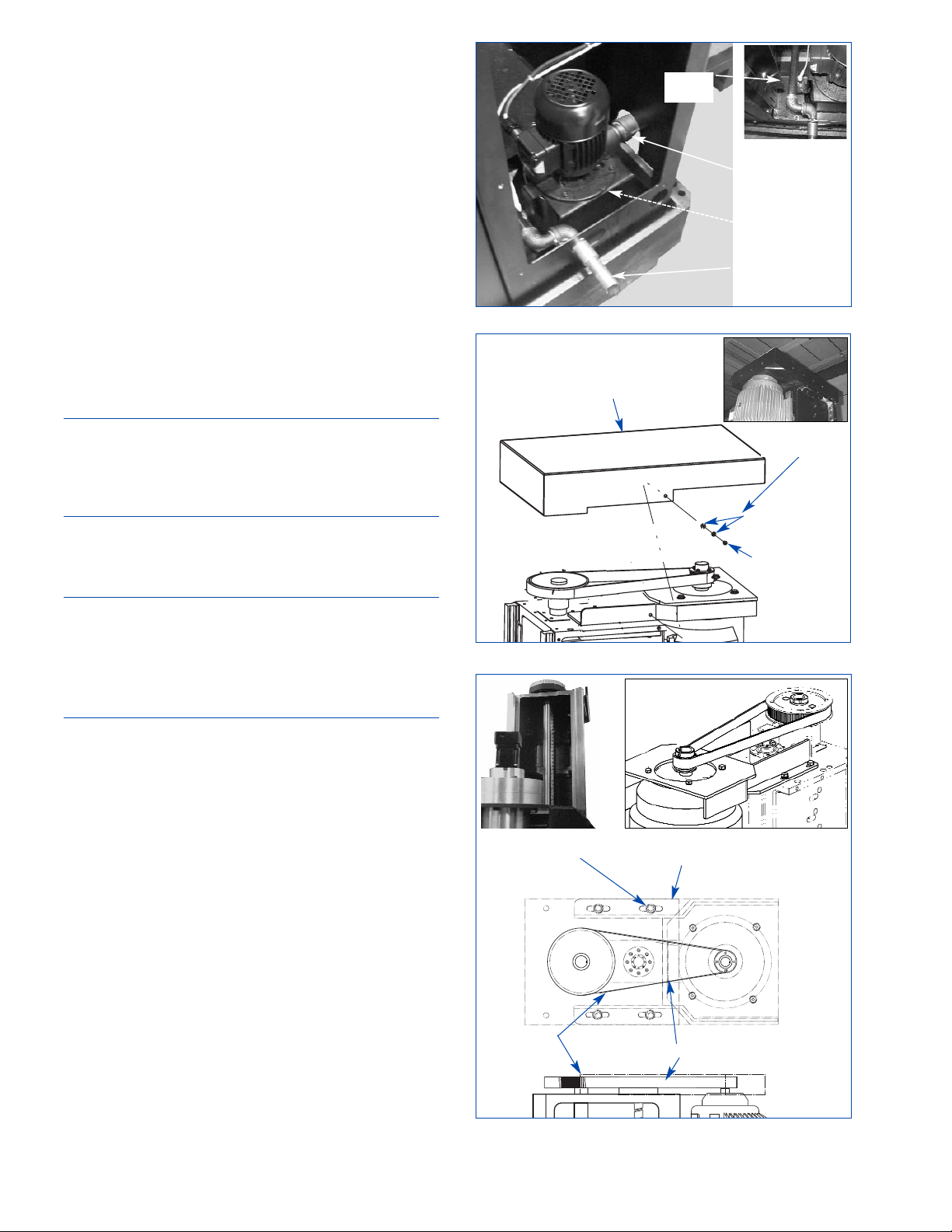
• Verify the operation of the lubrication system as
follows: Remove sheet metal covers attached to
carriage to get to points where grease lines enter
ball screw and ball spline. Disconnect both grease
lines at these locations. Under Diagnostics section
of software, set lube system to cycle 50 times. Verify
that grease is coming out of both grease lines.
(There may be some delay in grease coming out of
lines. This is normal.) If grease is not coming out of
one or both lines, then refer to Machine Operation
Troubleshooting section for corrective action.
• Inspect the ball spline and ball screw grooves for
pitting or wear. Any sign of this, if it occurs in a
region where the machine strokes during the honing
cycle, indicates a failure is imminent, and
replacement should be planned for the near future.
• Check the tension of the motor and spindle belts.
(See sections on Upper Spindle Belt and Lower
Spindle Belt.)
CAUTION
Both belts can be tensioned with the aid of screws
placed in the assembly. These screws are only to assist
in belt tensioning. Care must be taken that belts are not
over-tightened by attempting to tighten these screws.
• Examine the way covers for breaks or tears.
Replace as needed.
Every 10,000 km of Carriage Travel:
NOTE: The control system records cumulative
carriage travel. If your application runs at
recommended stroker speeds, 10,000 km of travel will
be reached after approximately 7000 hours of run time.
The operator station will indicate if the limit is close
to being reached.
• Grease the x-axis carriage and stroker carriage
runner blocks using Sunnen 90123 (Kluberplex
#BEM34-132 or its equivalent). The ends of the
runner block assemblies have Zerk fittings. Each
runner block will need approximately 2.2 ml. .
FILTER ELEMENT REPLACEMENT
Periodically check and clean Filter Element on the
side of the Electrical Enclosure, replaced as
required. To clean or replace the Filter Element
proceed as follows
(see Figure 4-2).
1. Turn OFF all power to Machine at Master
ON/OFF Switch.
2. Open Door to Electrical Enclosure.
3. Snap Filter Cover off Filter.
4. Remove Filter Element.
5. Clean Filter with warm water and a mild
detergent or mild industrial solvent.
22
FIGURE 4-5, Upper Spindle Belt
MOTOR SPINDLE
BRACKET
SCREWS
BELT
DEFLECTION
FIGURE 4-4, Motor Spindle Cover
MOTOR
SPINDLE
COVER
ACOUSTICAL
FOAM
WASHERS
SCREWS
FIGURE 4-3, Sump Pump
DRAIN
COVER
INLET
LINE
OUTLET
LINE
PUMP
SCREEN
Page 29
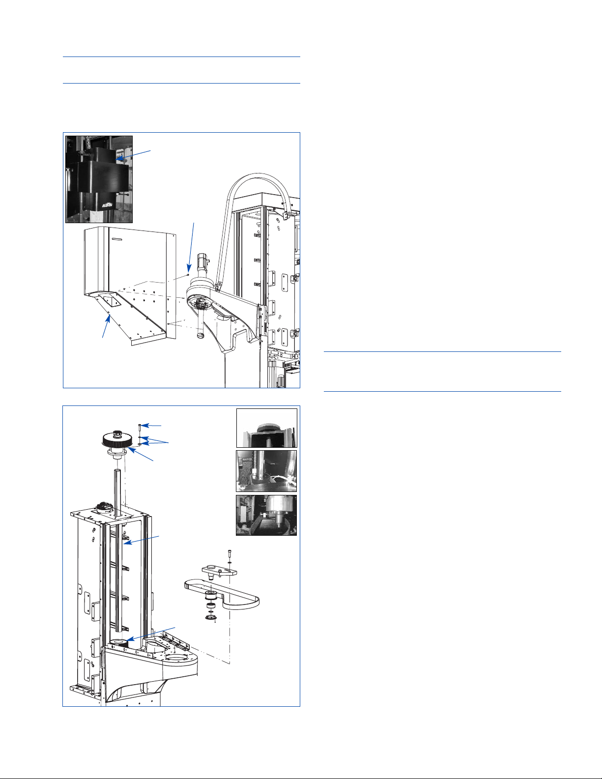
6. Rinse thoroughly with clean hot water and allow to dry.
7. Reinstall Filter Element.
NOTE: Replacement Elements and parts are
available through the Sunnen or your local supplier.
8. Snap Filter Cover into place over Filter Element.
9. Close and secure Door.
10. Turn ON power to the machine.
SUMP DRAIN CLEANING
Periodically check and clean Sump Drain (see
Figure 4-3)
. Sump Drain should be cleaned when
there is a noticeable drop in coolant pressure.
1. Turn OFF power at Master ON/OFF Switch.
2.
Remove Drain Cover in right side of machine base,
by removing six (6) button socket head capsrcews.
3. Remove sludge from sump and pump screen.
UPPER SPINDLE BELT
To replace Upper Spindle Belt, proceed as follows:
1. Remove Screws and Washers securing Motor
Spindle Cover, then remove Cover
(see Figure 4-4).
2. Loosen four (4) Screws holding Spindle Motor
Bracket to deck
(see Figure 4-5).
3. Loosen tension Setscrew in Tension Rod.
4. Slide spindle motor in toward spindle to loosen belt.
5. Remove old belt and replace with new belt.
6. Use tension Setscrew against Bracket to tension
belt before tightening Screws on Spindle Motor
Bracket. (New Belt: Tension belt so that deflection
at midway between pulleys is approximately 7,5mm
(.3in) when a 53N (12 lb) load is applied.)
NOTE: Used Belt: Tension belt so that deflection at
midway between pulleys is approximately 7,5mm
(.3in) when a 40N (9 lb) load is applied..
7. Tighten four (4) Screws holding Spindle Motor
Bracket to deck.
8. Reinstall Cover.
LOWER SPINDLE BELT
To replace Lower Spindle Belt:, proceed as follows:
1. Remove Upper Cover
(refer to Figure 4-4).
2. Loosen four (4) Screws holding Spindle Motor
Bracket to deck. Then loosen tension Setscrew in
Tension Rod
(refer to Figure 4-5).
3. Slide spindle motor in toward spindle to loosen
Upper Spindle Belt.
4. Remove Front Cover
(see Figure 4-6).
5. Remove Motor Sprocket Assembly, by removing
four (4) Screws and Washers securing assembly to
upper Deck by acess through top pulley
(see
Figure 4-7)
.
6. Slide Ball Spline Assembly out of lower
Sprocket
(refer to Figure 4-7). Block upper assembly
as required.
23
FIGURE 4-6, Front Cover
FRONT
COVER
FRONT
COVER
SCREWS
FIGURE 4-7, Lower Spindle Belt
WASHERS
SCREWS
MOTOR
SPROCKET
ASSEMBLY
BALL
SPLINE
ASSEMBLY
SPROCKET
Page 30
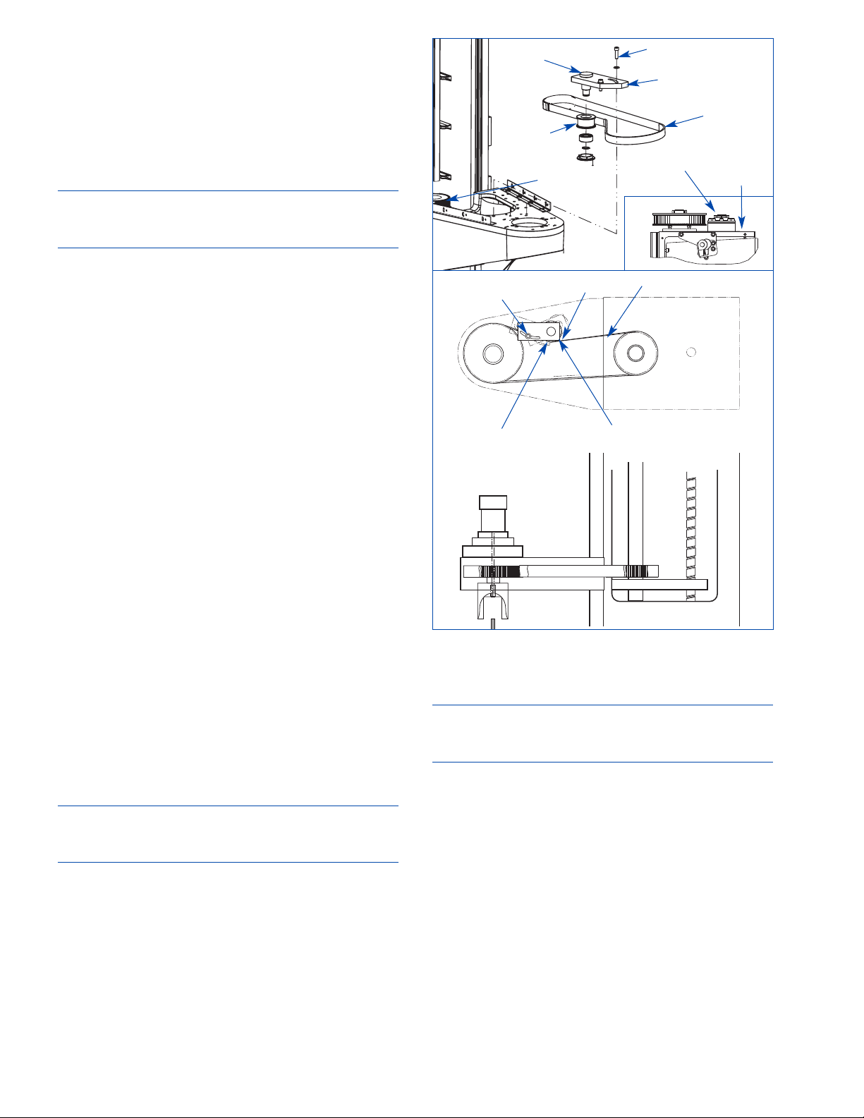
7. Loosen tension on Idler Pulley, by loosening
tension Screw in Tension Block Assembly
(see
Figure 4-8)
.
8. Remove old belt and replace with new belt.
9. Use tension Screw to tension belt. (New Belt:
Tension belt so that deflection at midway between
pulleys is approximately 9,5mm (.38in) when a 40N
(9 lb) load is applied.)
NOTE: Used Belt: Tension belt so that deflection at
midway between pulleys is approximately 9,5mm
(.38in) when a 29N (6.5 lb) load is applied..
10. Align Ball Spline Assembly with lower Sprocket
and reinstall Assembly in Sprocket.
11. Reinstall Motor Sprocket Assembly.
12. Use tension Setscrew against Bracket to tension
Upper Belt before tightening Screws on Spindle
Motor Bracket. Tension belt so that deflection at
midway between pulleys is approximately 7,5mm
(.3in) when a 53N (12 lb) load is applied.
13. Tighten four (4) Screws holding Spindle Motor
Bracket to deck.
14. Reinstall Front And Upper Covers.
PNEUMATIC LINES CHECK
Inspect Pneumatic Lines and Fittings monthly for
leaks or damaged parts. Replace parts as required.
Filter Element Replacement (if installed)
The Filter Element in the Airline Regulator should
be cleaned or replaced when there is a noticeable
drop in air pressure. To clean or replace the Filter
Element proceed as follows
(see Figure 4-9).
1. Turn OFF power to Machine at Master ON/OFF
Switch, Electrical Enclosure.
2. Turn Red Safety Valve to OFF and disconnect
In-Coming Factory airline at Quick-Disconnect.
3. Bleed any trapped air from filter.
4. Remove Bowl Assembly from Unit, by holding
down on release Button and rotating Bowl. Lay
Bowl aside for reinstallation.
CAUTION
Use care in disassembling to prevent O-Ring from
being damaged.
5. Unscrew Baffle; and remove Baffle and Filter
Element from Shaft.
6. Wipe Bowl and internal parts clean.
7. Install new Filter Element on Shaft. While
holding Filter in place, screw Baffle into place.
NOTE: Use Figure 4-9 to determine what filter is
installed on your machine and to determine what
replacement elements are needed.
8. Install Bowl Assembly with O-Ring on Unit.
Rotate Bowl until Button on side of Bowl snaps into
place, locking Bowl into Unit.
9. Connect In-Coming Factory airline at QuickDisconnect.
10. Turn Red Safety Valve ON.
11. Close top access Cover to the Machine.
12. Turn ON power to the Machine at Master
ON/OFF Switch, on Electrical Enclosure.
24
FIGURE 4-8, Lower Spindle Belt Tension
SPINDLE
STRAP
SCREWS
BELT
DEFLECTION
SCREW
TENSION
BLOCK
ASSEMBLY
SPROCKET
IDLER
PULLEY
BELT
IDLER
PULLEY
IDLER
PULLEY
STRAP
Page 31
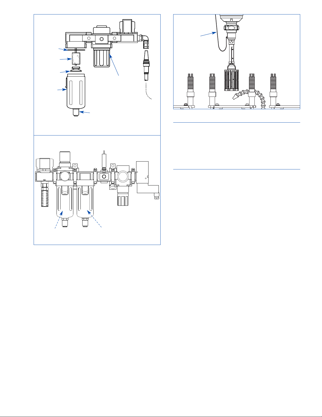
NOTE: When using Sunnen PH-Series Precision
Multi-Stone Honing Tools with integral air gage
available for in-process measurement for optimum
control of the bore diameter; inspect Pneumatic
Lines (airlines) and Fittings running to tool monthly
for leaks or damaged parts. Replace parts as required
(see Figure 4-10).
25
FIGURE 4-9, Pneumatic Line Check
FILTER
PFC1501
FILTER
PFC235
FILTER
ELEMENT
O RING
BAFFLE
FILTER
BOWL
REGULATOR
DRAIN
FIGURE 4-10, PH Tooling (Optional)
AIRLINES
Page 32

26
NOTES
Page 33

27
GENERAL
This section contains Troubleshooting information
in table form which should be used when problems
occur with machine. The table lists problems
encountered, possible causes, and solutions for
problems along with reference to section of manual
where detailed instructions may be found to correct
problems.
OPERATIONAL TROUBLESHOOTING
For suggestions on correcting problems with bore
conditions or with honing operation; consult
Table 5-1.
SECTION 5
TROUBLESHOOTING
TABLE 5-1, Operational Troubleshooting Index
PROBLEM PROBABLE CAUSE SOLUTIONS SEC. SCREEN
Tool generates 1. High feed rate A. Lower feed rate 3 Run / Diagnostic
high load 2. Worn tool A. Replace tool 2 Setup
3. Tool Loading (Metal particles A. Dress tool 3
on tool surface) B. Increase tool’s rpm
C. Check coolant* 1
Tool not cutting 1. Glazing A. Dress tool 2 Setup
B. Increase feed rate 3 Run / Diagnostic
C. Increase stroking speed 3 Run / Diagnostic
D. Replace tool, use softer 2 Setup
grit tool
E. Check coolant* 4
Slow stock 1. Improper spindle speed A. Increase spindle speed 3 Run / Diagnostic
removal 2. Inadequate tool feed rate A. Increase feed rate 3 Run / Diagnostic
3. Improper tool A. Replace tool 2 Setup
4. Inadequate tool's rpm A. Increase tool’s rpm 3 Run / Diagnostic
5. Improper or diluted coolant* A. Check coolant* 4
Poor stone life 1. Excessive tool feed rate A. Decrease feed rate 2-3 Run / Diagnostic
2. Inadequate tool's rpm A. Increase tool’s rpm 3 Run / Diagnostic
3. Improper tool A. Replace tool 2 Setup
4. Improper or dilute coolant* A. Check coolant* 4
5. Excessive stock removal A. Decrease stock removal 3
6. Excessive float in tool(s) A. Decrease tool float 2 Setup
7. Worn guide bushings A. Replace bushings 4
Bellmouth 1. Short or unbalanced part A. Shorten stroke length 3 Run / Diagnostic
2. Improper tool A. Replace tool 2 Setup
3. Improper stroke length A. Shorten stroke length 3 Run / Diagnostic
4. Excessive float in tool(s) A. Decrease tool float 2 Setup
5. Worn guide bushings A. Replace bushings 4
Barrel 1. Improper stroke length A. Shorten stroke length 3 Run / Diagnostic
B. Increase stroke length 3 Run / Diagnostic
C. Replace tool 2 Setup
2. Improper tool A. Replace tool 2 Setup
*NOTE: Many honing problems, such as poor tool life and rough finish, are caused by the following: the wrong
coolant, insufficient coolant, dirty coolant, or contaminated coolant. Use ONLY clean, full-strength Sunnen
Industrial Honing Oils or Water-Based Coolants. DO NOT dilute or “cut” the oil or coolant in your Machine with
other oils or coolants. Keep solvents and cleaning fluids away from your Machine.
Page 34

28
TABLE 5-1, Operational Troubleshooting Index (cont’d)
PROBLEM PROBABLE CAUSE SOLUTIONS SEC. SCREEN
Taper in Open 1. Improper overstroke A. Lengthen overstroke on 3 Run / Diagnostic
Hole tight end
2. Workpiece and Spindle A. Align Workpiece and 3 Run / Diagnostic
not aligned Spindle
3. Part/tool geometry A. Readjust stroke position 3
Taper in Blind 1. Improper stroke length A. Increase stroke length 3
Hole 2. Inadequate relief in blind end A. Provide sufficient relief
B. Short stroke tight end 3 Run / Diagnostic
C. Replace tool 2 Setup
3. Inadequate oil flow A. Adjust Oil Nozzle
Out-Of-Round 1. Undersize honing tool A. Replace tool 2 Setup
2. Workpiece flexing (thinwall) A. Decrease feed rate 3 Run / Diagnostic
B. Change method of fixturing 2
C. Decrease spindle speed 3 Run / Diagnostic
D. Reduce stock removal
3. Improper tool A. Replace tool 2 Setup
4. Excessive float in tool(s) A. Decrease tool float 2 Setup
5. Fixture not properly Aligned A. Adjust Fixture 2 Setup
Waviness 1. Improper tool length A. Use tool with sufficient 2 Setup
stone length to bridge
waviness in bore
Rainbow 1. Improper tool length A. Replace tool 2 Setup
(tool length should be
1-1/2 times bore length)
2. Improper overstroke A. Shorten overstroke 3 Run / Diagnostic
3. Improper tool A. Replace tool 2 Setup
Rough Finish 1. Improper feed rate A. Decrease feed rate 3 Run / Diagnostic
2. Improper tool A. Replace tool 2 Setup
3. Material loading tool A. Inspect & clean
4. Improper or diluted coolant* A. Check coolant* 4
Scratches in Bore 1. Improper feed rate A. Decrease feed rate 3 Run / Diagnostic
(Random) 2. Improper tool A. Replace tool 2 Setup
3. Improper or diluted coolant* A. Check coolant* 4
*NOTE: Many honing problems, such as poor tool life and rough finish, are caused by the following: the wrong
coolant, insufficient coolant, dirty coolant, or contaminated coolant. Use ONLY clean, full-strength Sunnen
Industrial Honing Oils or Water-Based Coolants. DO NOT dilute or “cut” the oil or coolant in your Machine with
other oils or coolants. Keep solvents and cleaning fluids away from your Machine.
Page 35

29
MACHINE OPERATION TROUBLESHOOTING
Error Messages:
The SV Series Machines have built in error
messages that will appear on display screen to alert
operator when machine has stopped due to an error,
problem, or incorrect setup.
Problems / Solutions:
WARNING
Some troubleshooting procedures require
examining parts inside machine enclosure.
ALWAYS have power OFF when guards are open.
If problem cannot be diagnosed by Power Off
inspection, then consult a Sunnen Service
Technician.
PROBLEM: Control system gives a message
indicating that the grease system is out of grease,
but grease can still be seen in the reservoir.
SOLUTIONS:
- An air pocket in the grease system can cause this
fault. Use the following procedure to bleed the air
from the system:
1. Disconnect all grease lines from their grease
injectors.
2. Remove all the grease injectors from the
manifold.
3. In the Diagnostics section of the control
software, set the grease system to cycle 100 times.
4. Watch the open ports in the manifold. As soon
as grease comes out an open port, then install that
injector in the open port.
NOTE: If you cannot hear the grease pump cycling,
then either the pump is defective or there is a loose
electrical connection.
5. When all injectors are installed begin looking for
grease to come out of the injectors. As soon as
grease can be seen coming out of an injector then
connect a grease line to that injector.
6. After all grease lines have been reconnected,
allow the system to finishing the 100 cycles. If no
faults occur in those 100 cycles then the air has
been successfully bled out of the system.
PROBLEM: Routine inspection of lubrication
system shows that grease is not coming out of one
or more grease lines.
SOLUTIONS:
- Remove the grease lines from the tops of the
grease injectors. Under the Diagnostics section of
the software, set the lube system to cycle 50 times.
1. If grease is seen coming out of the injectors,
then the problem is with the grease line. It is either
clogged or has a leak. In either case it should be
replaced.
2. If grease is not seen coming out of one or more
injector, then remove the injector(s) from the
manifold. Is grease coming out of the manifold
port(s) as the system continues to cycle? If not then
proceed to step 5.
3. If grease is coming out of the port(s) then
reinstall the injector(s). Only reinstall an injector
into a port where grease is present. If air is trapped
below the injector it will not work properly.
4. If grease does not come out of the reinstalled
injector, then the injector is not working properly.
An injector may be disassembled and cleaned to get
it to resume working, if that does not work then the
injector is defective and should be replaced.
5. If grease is not seen coming out of the port(s)
when the injectors are removed then air must be
bled from the grease pump. Open the air bleed port
just below the grease reservoir and continue cycling
the system until grease can be seen coming out of
the port. If this does not happen then the pump is
defective.
6. After taking the necessary corrective action and
reassembling, but before reattaching the grease lines
to the ball screw and ball spline, cycle the lube
system 50 times and verify that grease is coming
out of the lines.
Page 36

30
NOTES
Page 37
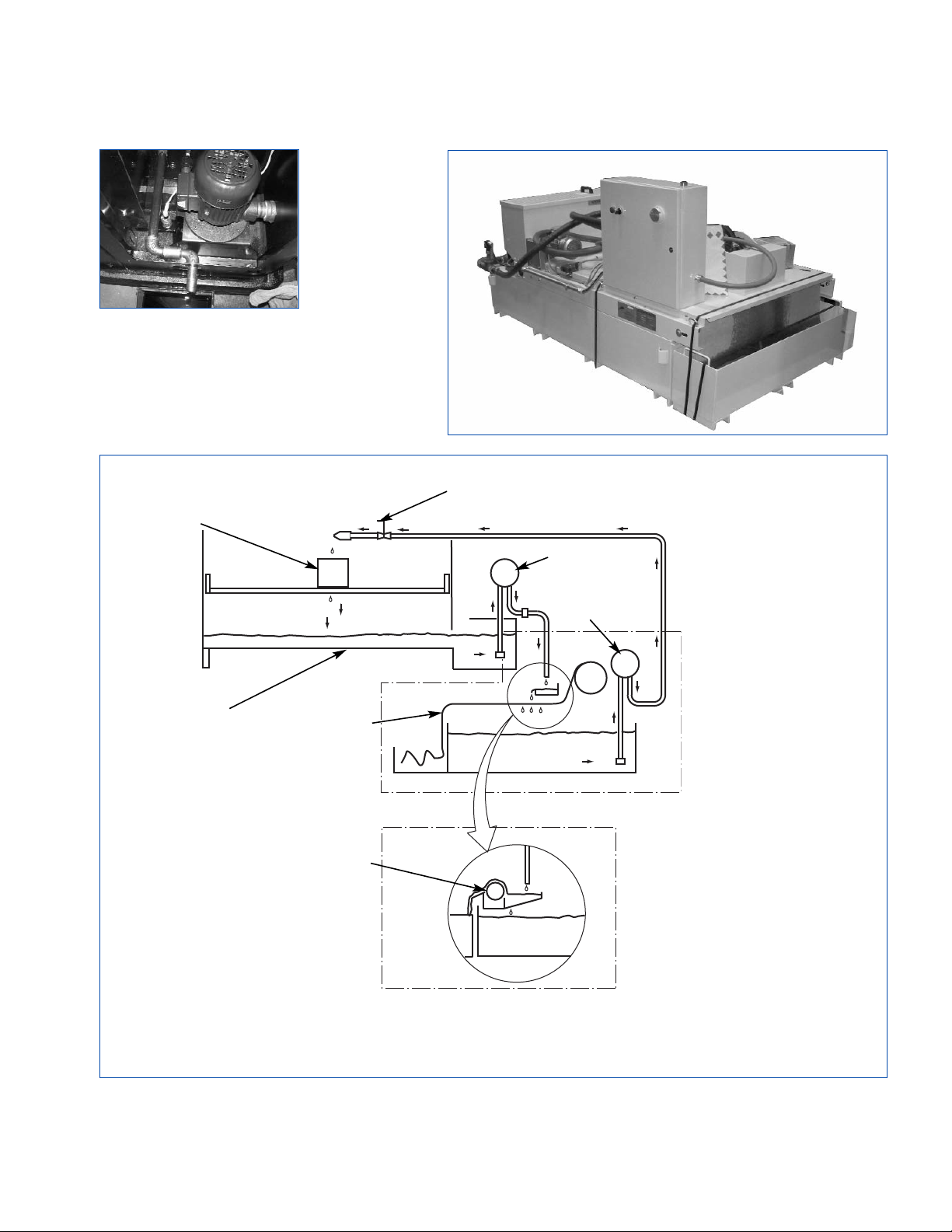
FLOW DIAGRAM
31
FIGURE A-1, Coolant System Flow Diagram
MAGNETIC
SEPARATOR
MACHINE
RESERVOIR
FLOW CONTROL
ON/OFF VALVE
SUMP PUMP
FILTERED
FLUID
WORKPIECE
OPTIONAL
COOLANT SYSTEM
with PAPER FILTER
A - COOLANT SYSTEM (OPT)
OPTIONAL
COOLANT SYSTEM
with MAGNETIC
SEPARATOR
PUMP
PAPER
FILTER
OPTIONAL
COOLANT SYSTEM
SUMP PUMP
Page 38

32
NOTES
Page 39
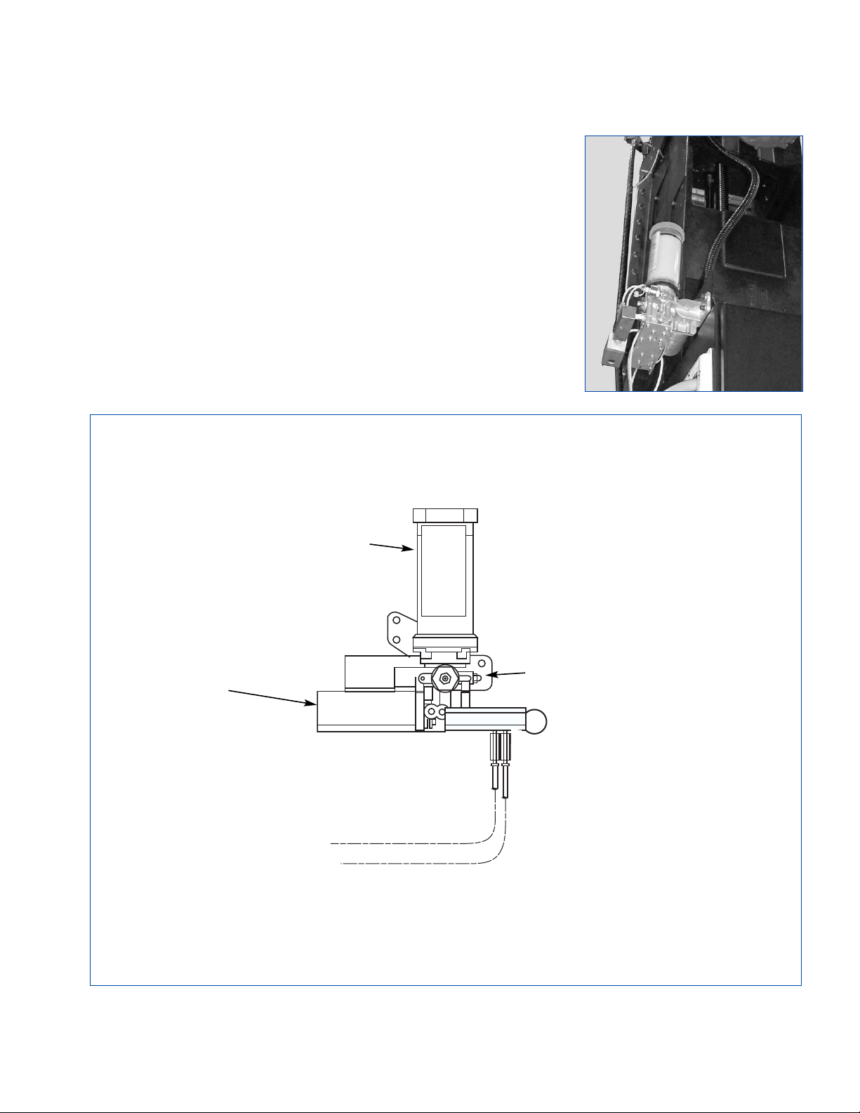
33
FLOW DIAGRAM
B - GREASE PUMP
FIGURE B-1, Grease Lubrication System Flow Diagram
LUBRICATOR
HOUSING
FILLER
PORT
TO BALLSCREW (STROKER)
TO BALLSPLINE (STROKER)
Page 40

34
NOTES
Page 41
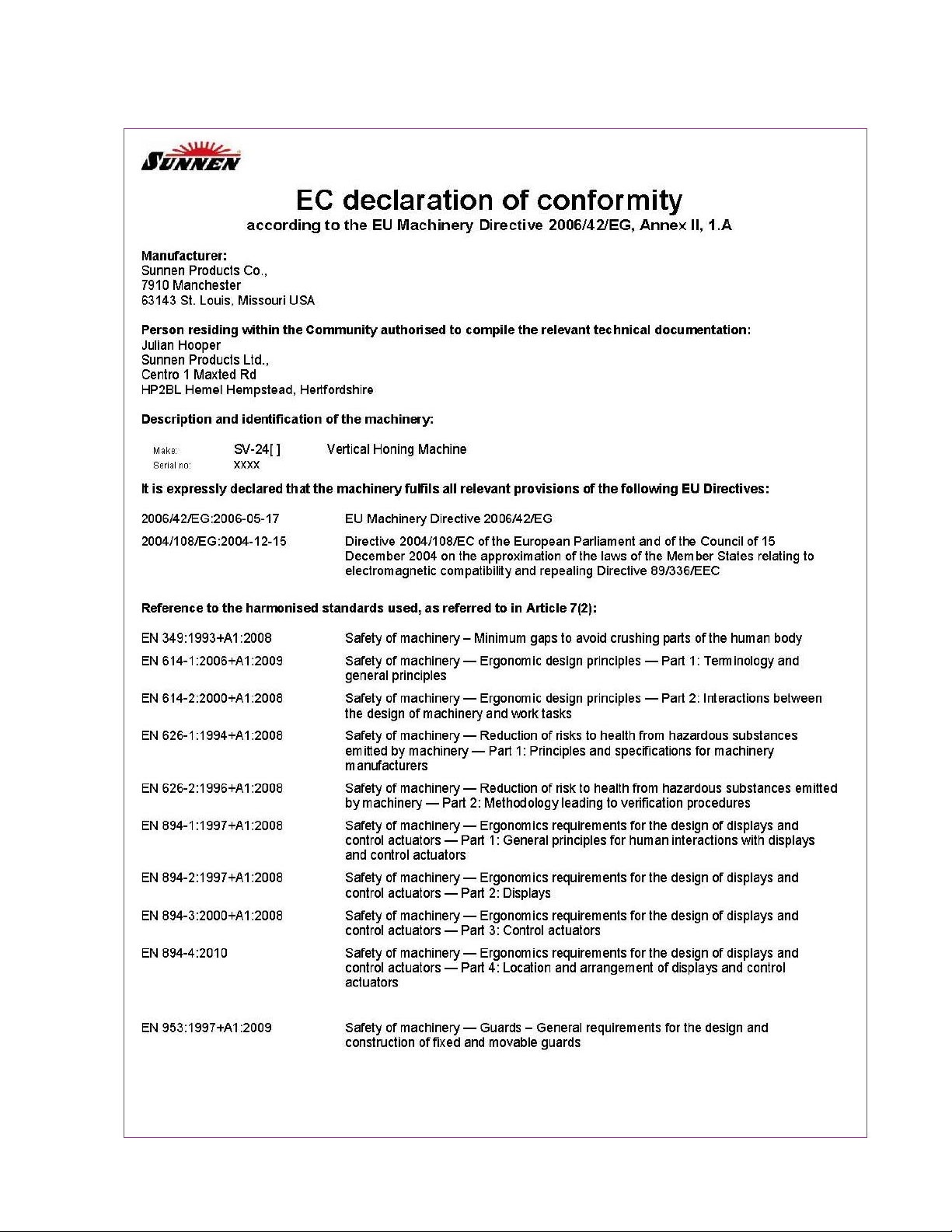
(1 OF 2)
C - DECLARATION OF CONFORMITY
35
SAMPLE
CE DOCUMENT
Page 42
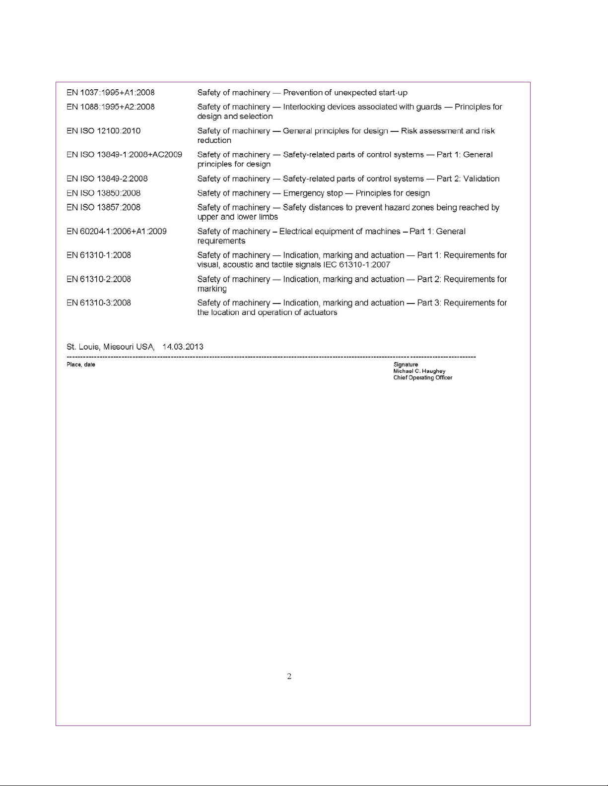
(2 OF 2)
C - DECLARATION OF CONFORMITY
36
SAMPLE
CE DOCUMENT
Page 43
37
Like any machinery, this equipment may
be dangerous if used improperly. Be
sure to read and follow instructions for
operation of equipment.
WARNING
An Arc Flash Hazard Exists. Follow safe work
practices and wear appropriate Personal
Protective Equipment. Follow proper
lockout/tagout procedures.
Failure to comply
can result in death or injury.
Page 44
FRACTION / DECIMAL / MILLIMETER EQUIVALENTS CHART
INCH
FRACTION DECIMAL
MILLIMETER
. . . . .003937 0,1000
. . . . .007874 0,2000
. . . . .011811 0,3000
1/64 .015625 0,3969
. . . . .015748 0,4000
. . . . .019685 0,5000
. . . . .023622 0,6000
. . . . .027559 0,7000
1/32 .031250 0,7938
. . . . .031496 0,8000
. . . . .035433 0,9000
. . . . .039370 1,0000
3/64 .046875 1,1906
1/16 .062500 1,5875
5/64 .078125 1,9844
. . . . .078740 2,0000
3/32 .093750 2,3813
7/64 .109375 2,7781
. . . . .118110 3,0000
1/8 .125000 3,1750
9/64 .140625 3,5719
5/32 .156250 3,9688
. . . . .157480 4,0000
11/64 .171875 4,3656
3/16 .187500 4,7625
. . . . .196850 5,0000
13/64 .203125 5,1594
7/32 .218750 5,5563
15/64 .234375 5,9531
. . . . .236220 6,0000
1/4 .250000 6,3500
17/64 .265625 6,7469
. . . . .275591
7,0000
INCH
FRACTION DECIMAL
MILLIMETER
9/32 .281250 7,1438
19/64 .296875 7,5406
5/16 .312500 7,9375
. . . . .314961 8,0000
21/64 .328125 8,3344
11/32 .343750 8,7313
. . . . .354331 9,0000
23/64 .359375 9,1281
3/8 .375000 9,5250
25/64 .390625 9,9219
. . . . .393701 10,0000
13/32 .406250 10,3188
27/64 .421875 10,7156
. . . . .433071 11,0000
7/16 .437500 11,1125
29/64 .453125 11,5094
15/32 .468750 11,9063
. . . . .472441 12,0000
31/64 .484375 12,3031
1/2 .500000 12,7000
. . . . .511811 13,0000
33/64 .515625 13,0969
17/32 .531250 13,4938
35/64 .546875 13,8906
. . . . .551181 14,0000
9/16 .562500 14,2875
37/64 .578125 14,6844
. . . . .590551 15,0000
19/32 .593750 15,0813
39/64 .609375 15,4781
5/8 .625000 15,8750
. . . . .629921 16,0000
41/64 .640625 16,2719
INCH
FRACTION DECIMAL
MILLIMETER
21/32 .656250 16,6688
. . . . .669291 17,0000
43/64 .671875 17,0656
11/16 .687500 17,4625
45/64 .703125 17,8594
. . . . .708661 18,0000
23/32 .718750 18,2563
47/64 .734375 18,6531
. . . . .748031 19,0000
3/4 .750000 19,0500
49/64 .765625 19,4469
25/32 .781250 19,8438
. . . . .787402 20,0000
51/64 .796875 20,2406
13/16 .812500 20,6375
. . . . .826772 21,0000
53/64 .828125 21,0344
27/32 .843750 21,4313
55/64 .859375 21,8281
. . . . .866142 22,0000
7/8 .875000 22,2250
57/64 .890625 22,6219
. . . . .905512 23,0000
29/32 .906250 23,0188
59/64 .921875 23,4156
15/16 .937500 23,8125
. . . . .944882 24,0000
61/64 .953125 24,2094
31/32 .968750 24,6063
. . . . .984252 25,0000
63/64 .984375 25,0031
1 1.000000 25,4000
1-1/16 1.062500 26,9880
FORMULAS:
MULTIPLY BY TO GET MULTIPLY BY TO GET
INCHES (in) x 25.4 = MILLIMETERS (mm) MILLIMETERS (mm) x 0.03937 = INCHES (in)
FEET (ft) x 0.3048 = METERS (m) METERS (m) x 3.281 = FEET (ft)
PRINTED IN U.S.A. 1304 ©COPYRIGHT SUNNEN®PRODUCTS COMPANY 2013, ALL RIGHTS RESERVED
SUNNEN PRODUCTS COMPANY
7910 Manchester Road, St. Louis, MO 63143 U.S.A.
Phone: 314-781-2100 Fax: 314-781-2268
U.S.A. Toll-Free Sales and Service:1-800-325-3670
International Division Fax: 314-781-6128
http://www.sunnen.com
e-mail: [email protected]
S
WITZERLAND
– S
UNNEN
AG
Phone: ++ 41 71 649 33 33 Fax: ++ 41 71 649 34 34
www.sunnen.ch e-mail: [email protected]
I
TALY
- S
UNNENITALIA
S.R.L.
Phone: 39 02 383 417 1 Fax: 39 02 383 417 50
www.sunnenitalia.com e-mail: [email protected]
F
RANCE
– S
UNNEN
SAS
Phone: +33 01 69 30 0000 Fax: +33 01 69 30 1111
www.sunnen.fr e-mail: [email protected]
B
ELGIUM
– S
UNNENBENELUX
BVBA
Phone: +32 38 80 28 00 Fax: +32 38 44 39 01
www.sunnen.be e-mail: [email protected]
UK – S
UNNENPRODUCTSLTD
.
Phone: ++ 44 1442 39 39 39 Fax: ++ 44 1442 39 12 12
www.sunnen.co.uk e-mail: [email protected]
P
OLAND
– S
UNNENPOLSKASP
. Z O.O.
Phone: +48 22 814 34 29 Fax: +48 22 814 34 28
www.sunnen.pl e-mail: [email protected]
R
USSIA
– S
UNNEN
RUS
Phone: +7 495 258 43 43 Fax: +7 495 258 91 75
www.sunnen.ru e-mail: [email protected]
C
ZECHREPUBLIC
– S
UNNEN
S.R.O.
Phone: +420 383 376 317 Fax: +420 383 376 316
www.sunnen.cz e-mail: [email protected]
C
HINA
– S
HANGHAISUNNENMECHANICALCO
., LTD.
Phone: 86 21 5813 3322 Fax: 86 21 5813 2299
www.sunnensh.com e-mail: [email protected]
Sunnen®reserves the right to change or
revise specifications and product design
in connection with any feature of our
products contained herein. Such changes
do not entitle the buyer to corresponding
changes, improvements, additions, or
replacements for equipment, supplies or
accessories previously sold. Information
contained herein is considered to be
accurate based on available information
at the time of printing. Should any
discrepancy of information arise, Sunnen
recommends that user verify discrepancy
with Sunnen before proceeding.
“SUNNEN®AND THE SUNNEN LOGO ARE REGISTERED TRADEMARKS OF SUNNEN PRODUCTS COMPANY.”
 Loading...