

Page 1
Operating
and Maintenance
INSTRUCTIONS
for
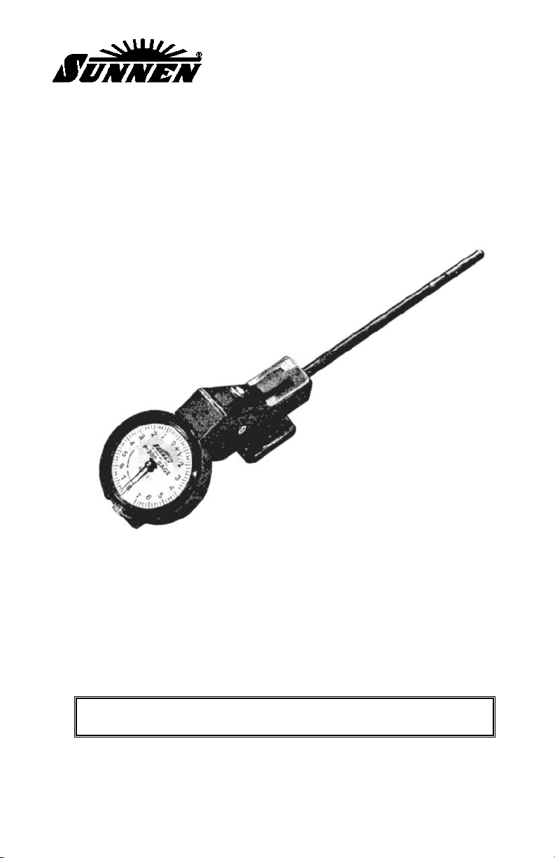
SUNNEN®P-310
VALVE GUIDE GAGE SET
SUNNEN®PRODUCTS CO • 7910 MANCHESTER • ST. LOUIS, MO 63143 U.S.A. • PHONE: 314-781-2100
I-P-310D
READ THE FOLLOWING INSTRUCTIONS THOROUGHLY AND CAREFULLY BEFORE UNPACKING,
OR OPEARTING THE SUNNEN
®
VALVE GUIDE GAGE SET.
“SUNNEN AND THE SUNNEN LOGO ARE REGISTERED TRADEMARKS OF SUNNEN PRODUCTS COMPANY.”
Page 2
ii
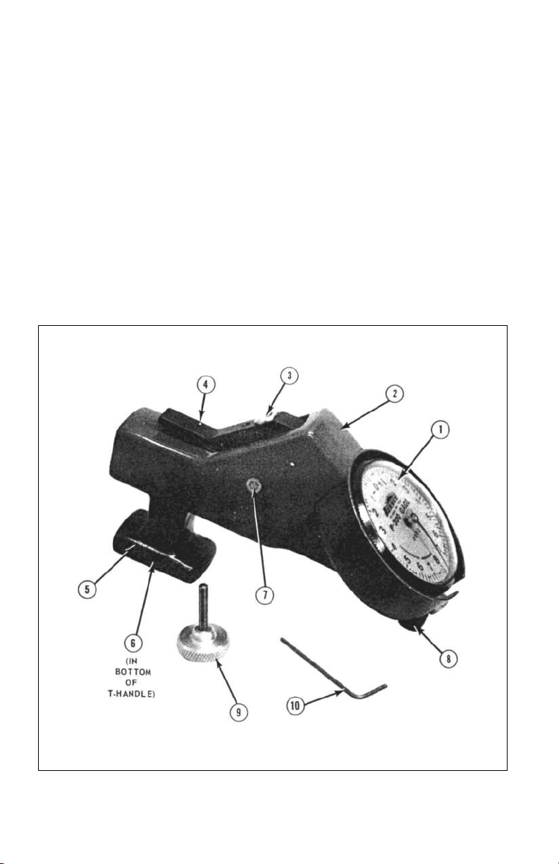
FIGURE 1
CONTENTS
DESCRIPTION
P-300 Gage . . . . . . . . . . . . . . . . . . . . . . . . . . . . . . . . . . . . . . . . . . . . 1
Gaging Probes . . . . . . . . . . . . . . . . . . . . . . . . . . . . . . . . . . . . . . . . . . 2
OPERATION
Assembling Probes to Gage. . . . . . . . . . . . . . . . . . . . . . . . . . . . . . . . 3
Installing Vlaves in Setting Fixture . . . . . . . . . . . . . . . . . . . . . . . . . . 4
Setting Gage to Read Valve Size . . . . . . . . . . . . . . . . . . . . . . . . . . . . 4
Using the Gage . . . . . . . . . . . . . . . . . . . . . . . . . . . . . . . . . . . . . . . . . 5
MAINTENANCE
Maintenance of Probe . . . . . . . . . . . . . . . . . . . . . . . . . . . . . . . . . . . . 7
Maintenance of Retracting Lever. . . . . . . . . . . . . . . . . . . . . . . . . . . . 7
Page 3

1
DESCRIPTION
The P-310 Gage Set consists of:
P-300 Gage
P-312 Probe - 5/16" (7.9 mm) diameter*
P-344 Probe - 11/32" (8.7 mm) diameter*
P-375 Probe - 3/8" (9.5 mm) diameter*
P-610 Setting Fixture
P-650 Metal Storage Case - stores all items listed above;
has space for 8 probes Instruction Manual
P-300 Gage
Your new P-300 Gage is a hand-held comparator-type gage which uses
probes to measure the clearance between valve stems and guides (see
Figure 1). It will gage reamed, honed, knurled, or bronze insert guides.
Any desired diameter within the range of the probe used can be set into
the gage.
1. DIAL INDICA
TOR - Reads in .0002" (0.005 mm) increments over
or under the set diameter. Each numeral marks .001" (0.05 mm); total
range of dial is .015" (0.37 mm).
2. GAGE BODY
- Incorporates probe adapter for seating and holding
probe.
3. ADJUSTMENT SCREW
- Used to "zero" gage when setting;
operated with Wrench, Item 9.
4. RETRACTING LEVER
- Depress to reduce gage point diameter
when inserting probe in setting fixture, valve guide, or when making
readings at various points along valve guide.
5. T-HANDLE
- Used for holding and balancing gage when measuring
valve guides.
6. PROBE LOCKING SCREW - Securely holds probe; loosen and
tighten with Wrench, Item 9. 7. PIVOT BEARINGS - Self-locating
design assures repeatability in readings.
8. SUPPOR
TING FOOT - Provides a rest point in conjunction with T-
Handle to support gage.
9. 1/8" (3 mm) HEX WRENCH WITH KNURLED KNOB
- Has
rounded knurled handle; used for locking probe in place and adjusting
gage to desired setting.
10. .050" (1,25 mm) HEX KEY WRENCH - Used when servicing
Retracting Lever.
Page 4

2
Gaging Probes
Each probe is self-contained but can be disassembled for service (see
Figure 2). When assembled to Gage Body and correctly set with a
master of known size, a probe will gage any diameter within its design
range (refer to Table 1).
1. GAGING POINTS
- Opposed Points are long enough to bridge the
grooves in knurled guides and give accurate measurements in all types
of guides.
2. HEAD
- Ground diameter gives proper seat in P-300 Gage. Flat on
Head assures correct installation. Countersink opposite flat provides
positive locator for Probe Locking Screw (Item 6, Figure 1).
3. WEDGE
- Transfers size from Gaging Points to Gage.
4. 5/64" (2 mm) HEX KEY WRENCH
- Used for servicing probe.
FIGURE 2
AVAILABLE RANGE
PROBES INCHES MILLIMETERS
P-250 Probe (1 /4") .238 to .278 6,05 to 7,06
P-281 Probe (9/32") .269 to .309 6,83 to 7,85
*P-312 Probe (5/16") .300 to .340 7,62 to 8,64
*P-344 Probe (11 /32") .332 to .372 8,43 to 9,45
*P-375 Probe (3/8") .363 to .403 9,22 to 10,24
P-406 Probe (13/32") .394 to .434 10,01 to 11,02
P-438 Probe (7/16") .426 to .466 10,82 to 11,84
P-469 Probe (15/32") .457 to .497 11,61 to 12,62
P-500 Probe (1 /2") .488 to .528 12,40 to 13,41
TABLE 1, Gaging Probes
*Included with P-310 Valve Guide Gage Set
Page 5

3
OPERATION
ASSEMBLING PROBE TO GAGE
1. Select correct probe.
2. Use Wrench to back out Probe Locking Screw.
3. Install head of probe into Gage Body with flat toward Retracting
Lever and countersink toward T-Handle.
4. Hold probe tightly into Gage Body and tighten Probe Locking
Screw with Wrench (see Figure 3).
5. Insert Wrench into Adjustment Screw and rotate it counterclockwise
to retract gaging points. Place gage in its nest in storage case.
INSTALLING VALVES IN SETTING FIXTURE
1. Select two Valves to use in setting fixture.
NOTE: Valves must have
identical stem diameters. If
intake and exhaust Valves are
of different diameters, reset
gage for each, using the
appropriate Valves.
2. Clean Valve Stems and
Blocks (see Figure 4). Place
Valves between Blocks and
FIGURE 3
FIGURE 4
Page 6

4
tighter Thumb Screw with fingers, then back off Thumb Screw 1/8 to
1/4 turn to eliminate possibility of distortion in Blocks.
CAUTION
Do not use pliers or wrench.
3. Turn Eccentric until "V" is in lowest posi-tion. Setting fixture is
now ready to use.
SETTING GAGE TO READ VALVE SIZE
1. Insert Probe between Blocks all the way to the stop, and rest in "V"
of Eccentric with gage dial up (see Figure 5).
2. Set gage to approximately "0" with Wrench.
3. Turn Eccentric until indicator reaches largest plus (+) reading.
NOTE: You may have to repeat Step 2 to get largest (+) reading.
4. Rotate Probe slightly until indicator reaches largest minus (-)
reading (refer to Figure 5). (Do not force when rotating Probe. It may
require depressing retracting lever to reset).
5. Set gage to "0" with Wrench and rotate Probe slightly to check that
needle returns to "0".
FIGURE 5
Page 7

5
6. Carefully remove Wrench without disturbing gage setting and store
in setting fixture.
7. Recheck gage setting by rotating Probe.
NOTE: Do not move dial face. Fine adjust ments should be made with
Wrench.
8. Gage is now set to valve size, and is ready to use in checking
condition of guides. Minus (-) readings will indicate interference and
plus (+) readings will indicate clearance.
NOTE: Dial indicator needle is limited to approximately 1-1/4
revolutions.
USING THE GAGE
1. Brush or blow chips and abrasive from valve guides to be checked.
NOTE: Guides must be clean to obtain accurate readings.
2. Press Retracting Lever with thumb and insert probe into guide.
Release Lever (see Figure 6).
FIGURE 6
Page 8

6
NOTE: Guide can be gaged from either side of head. For accurate gaging,
do not let Gaging Points extend beyond either end of valve guide bore. If
Probe should come out of bore, press Retracting Lever and reposition
Points inside guide bore.
3. Readings may now be taken at various places along guide. (When
changing position of Probe Gaging Points in valve guide or inserting
and removing Probe from valve guide, depress retracting lever to avoid
damage to gage points.)
4. Any area of the guide exceeding the desired clearance ;plus (+)
reading would indicate need for correction.
NOTE: Recommended clearances vary with engine manufacturer and type
of engine. The intake and exhaust guides may require different clear-ances.
Consult manufacturer's recommendations for specific clear-ances.
5. When gaging, do not touch Retracting Lever, as reading errors may
occur.
6. In gaging any specific spot, move gage up and down from left to
right to get largest plus (+) reading.
FIGURE 7
TUBE
SPRING
HEAD
SET
SCREW
WEDGE
Page 9

7
MAINTENANCE
MAINTENANCE OF PROBE
If gaging action becomes sluggish or if gaging points stick open, probe
may be disassembled for cleaning (see Figure 7).
1. Loosen Set Screw with 5/64" (2 mm) Hex Key Wrench and remove
Head.
2. Remove Wedge from Tube carefully. Do not lose Spring.
3. Flush Tube with an oily solvent and then check point movement
using Wedge.
4. Relubricate Wedge with 5-10 SAE machine oil and reassemble. Be
certain Screw engages countersink in Tube.
5. Check Wedge movement. Spring must push Wedge out to release all
pressure on Gaging Points.
MAINTENANCE OF RETRACTING LEVER
If Retracting Lever becomes sluggish in operation, it may be removed
for cleaning (see Figure 8).
1. Insert .050" (1.25 mm) Hex Key Wrench into small hole in Lever.
Loosen approximately one turn.
2. Remove Wrench and use end to push Shaft out of body.
FIGURE 8
SHAFT
.050”
HEX KEY WRENCH
RETRACTING
LEVER
Page 10

8
3. With Shaft removed, Lever may be lifted out of body for servicing.
CAUTION
A small Spring is used to provide gaging, force. This Spring is nested in two
Sockets (one in the Lever and one in the body). Do not lose this Spring or
gage will be inoperative (see Figure 9).
4. Check Indicator by pressing Anvil in. If needle moves freely and
returns to original position, indicator is OK.
5. Wipe Lever and Shaft to clean (do not dip in solvents . . . as grit
may be washed into Adjustment Screw).
6 Brass Pivot Bearings may be cleaned, but do not scratch or mar
them. Do not remove spring clips on Bearings.
7. To reassemble, place Spring in Socket in Lever and hold in place.
Insert Lever into body. Be sure Spring is in Socket in body.
8. Align hole in Lever with Pivot Bearings. Insert Shaft and center end
to end. Then retighten Set Screw in lever.
9. Depress Lever to make sure that indicator needle moves freely and
returns to its original position.
FIGURE 9
ANVIL
SPRING
SOCKETS
Page 11

9
NOTES
Page 12

PRINTED IN U.S.A. 0212 ©COPYRIGHT SUNNEN PRODUCTS COMPANY 2002, ALL RIGHTS RESERVED
SUNNEN PRODUCTS COMPANY
7910 Manchester Ave., St. Louis, MO 63143 U.S.A.
Phone: 314-781-2100 Fax: 314-781-2268
U.S.A. Toll-Free Sales and Service –
Automotive: 1-800-772-2878 • Industrial: 1-800-325-3670
International Division Fax: 314-781-6128
http://www.sunnen.com
e-mail: sunnen@sunnen.com
SUNNEN PRODUCTS LIMITED
No. 1 Centro, Maxted Road
Hemel Hempstead, Herts HP2 7EF ENGLAND
Phone: ++ 44 1442 39 39 39 Fax: ++ 44 1442 39 12 12
SUNNEN AG
Fabrikstrasse 1
8586 Ennetaach-Erlen, Switzerland
Phone: ++ 41 71 648 16 16 Fax: ++ 41 71 648 31 31
SHANGHAI SUNNEN MECHANICAL CO., LTD.
889 Kang Qiao East Road, PuDong
Shanghai 201319, P.R. China
Phone: 86 21 5 813 3322 Fax: 86 21 5 813 2299
SUNNEN ITALIA S.R.L.
Viale Stelvio 12/15
20021 Ospiate di Bollate (MI) Italy
Phone: 39 02 383 417 44 Fax: 39 02 383 417 50
Sunnen®reserves the right to change or
revise specifications and product design
in connection with any feature of our
products contained herein. Such
changes do not entitle the buyer to
corresponding changes, improvements,
additions, or replacements for equipment,
supplies or accessories previously sold.
Information contained herein is considered
to be accurate based on available
information at the time of printing.
Should any discrepancy of information
arise, Sunnen recommends that user
verify the discrepancy with Sunnen
before proceeding.
“SUNNEN AND THE SUNNEN LOGO ARE REGISTERED TRADEMARKS OF SUNNEN PRODUCTS COMPANY.”
 Loading...