

Page 1
SUNNEN®PRODUCTS COMPANY • 7910 MANCHESTER AVENUE • ST. LOUIS, MO 63143, U.S.A. • PHONE: 314-781-2100
READ THE FOLLOWING INSTRUCTIONS THOROUGHLY AND CAREFULLY BEFORE UNPACKING,
INSPECTING, OR INSTALLING THE SUNNEN®HONING MACHINE.
I-LBB-661H
Installation, Setup
and Operation
INSTRUCTIONS
for
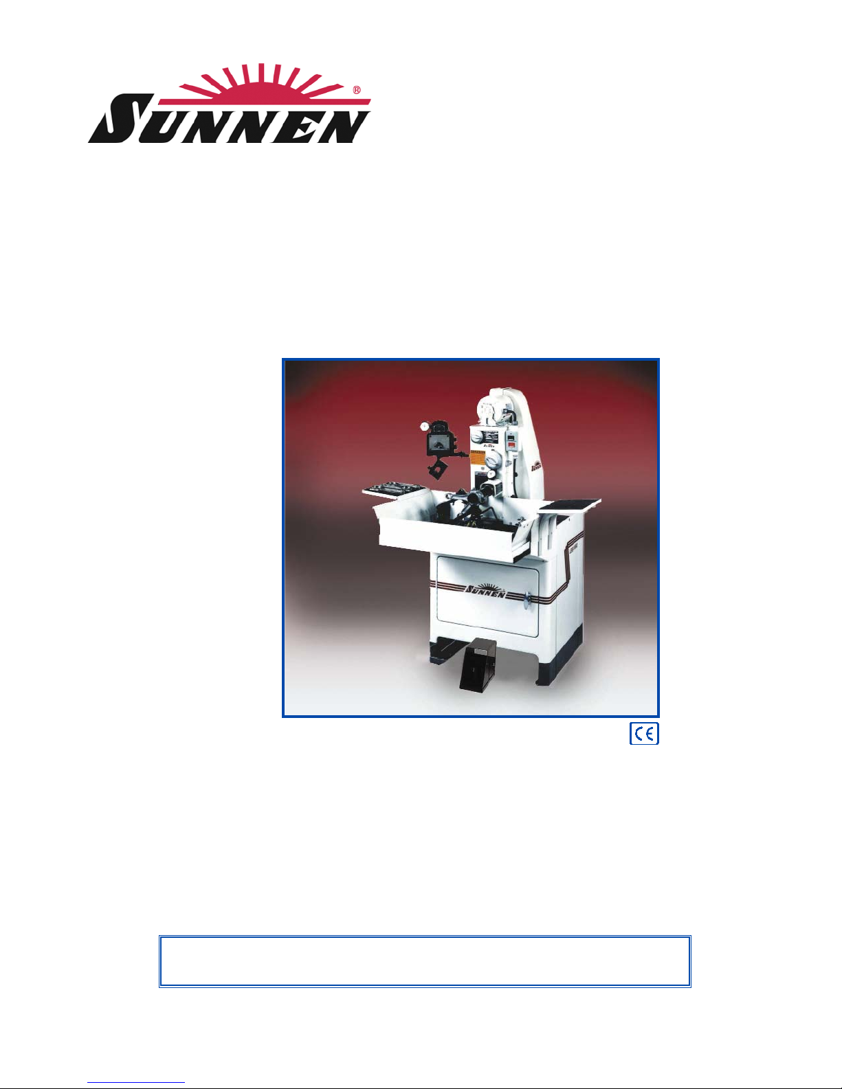
SUNNEN®HONING MACHINE
Model LBB-1660
“SUNNEN AND THE SUNNEN LOGO ARE REGISTERED TRADEMARKS OF SUNNEN PRODUCTS COMPANY.”
Page 2

GENERAL INFORMATION
The Sunnen®equipment has been designed and engineered for a wide variety of parts within the capacity and limitation of the equipment. With proper care
and maintenance this equipment will give years of service.
READ THE FOLLOWING INSTRUCTIONS CAREFULLY AND THOROUGHLY BEFORE UNPACKING, INSPECTING, OR INSTALLING THIS EQUIPMENT.
IMPORTANT:
Read any supplemental instructions BEFORE installing this equipment. These supplemental instructions give you important information to
assist you with the planning and installation of your SUNNEN
®
equipment.
Sunnen Technical Service Department is available to provide telephone assistance for installation, programming, & troubleshooting of your Sunnen
equipment. All support is available during normal business hours, 8:00 AM to 4:30 PM Central Time.
Review all literature provided with your Sunnen equipment. This literature provides valuable information for proper installation, operation, and maintenance
of your equipment. Troubleshooting information can also be found within the Instructions. If you cannot find what you need, call for technical support.
Where applicable, programming information for your Sunnen equipment is also included. Most answers can be found in the literature packaged with your
equipment.
Help us help you. When ordering parts, requesting information, or technical assistance about your equipment, please have the following
information available:
• Have ALL MANUALS on hand. The Customer Services Representative or Technician will refer to it.
• Have Model Number and Serial Number printed on your equipment Specification Nameplate.
• Where Applicable: Have Drive model and all nameplate data. Motor type, brand, and all nameplate data.
For Troubleshooting, additional information may be required:
• Power distribution information (type - delta, wye, power factor correction; other major switching devices used, voltage fluctuations)
• Installation Wiring (separation of power & control wire; wire type/class used, distance between drive and motor, grounding).
• Use of any optional devices/equipment between the Drive & motor (output chokes, etc.).
For fast service on your orders call:
Sunnen Automotive Customer Service toll free at: 1-800-772-2878
Sunnen Industrial Customer Service toll free at: 1-800-325-3670
Customers outside the USA, contact your local authorized Sunnen Distributor.
Additional information available at:
http://www.sunnen.com or e-mail: [email protected]
NOTE: Sunnen reserves the right to change or revise specifications and product design in connection with any feature of our products contained herein.
Such changes do not entitle the buyer to corresponding changes, improvements, additions, or replacements for equipment, supplies or accessories
previously sold. Information contained herein is considered to be accurate based on available information at the time of printing. Should any discrepancy of
information arise, Sunnen recommends that user verify the discrepancy with Sunnen before proceeding.
ESD PREVENTION REVIEW
Let's review the basics of a sound static control system and its effective implementation. First, in the three step plan:
1. Always ground yourself when handling sensitive components or assemblies.
2. Always use a conductive or shielded container during storage or transportation. These materials create a Faraday
cage which will isolate the contents from static charges.
3. Open ESD safe containers only at a static safe work station.
At the static safe work station, follow these procedures before beginning any work:
A. Put on your wrist strap or foot grounding devices.
B. Check all grounding cords to make sure they are properly connected to ground, ensuring the effective dissipation of sta-
tic charges.
C. Make sure that your work surface is clean and clear of unnecessary materials, particularly common plastics.
D. Anti-static bubble wrap has been included for use at the machine when an ESD safe workstation is not available.
You are now properly grounded and ready to begin work. Following these few simple rules and using a little common sense will go a long
way toward helping you and your company in the battle against the hazards of static electricity. When you are working with ESD sensitive devices, make sure you:
GROUND
ISOLATE
NEUTRALIZE
ii
Page 3

SUNNEN®LIMITED PRODUCT WARRANTY
SUNNEN®Products Company and its subsidiaries (SPC) warrant that all new SPC honing machines, gaging equipment, tooling, and related equipment will
be free of defects in material and/or workmanship for a period of one year from the date of original shipment from SPC.
Upon prompt notification of a defect during the one-year period, SPC will repair, replace, or refund the purchase price, with respect to parts that prove to be
defective (as defined above). Any equipment or tooling which is found to be defective from improper use will be returned at the customer's cost or repaired
(if possible) at customer's request. Customer shall be charged current rates for all such repair.
Prior to returning any SPC product, an authorization (RMA#) and shipping instructions must be obtained from the Customer Service Department or items
sent to SPC will be returned to the customer.
Warranty Limitations and Exclusions This Warranty does not apply to the following:
• Normal maintenance items subject to wear and tear: (belts, fuses, filters, etc).
• Damages resulting from but not limited to:
› Shipment to the customer (for items delivered to customer or customer's agent F.O.B., Shipping Point)
› Incorrect installation including improper lifting, dropping and/or placement
› Incorrect electric power (beyond +/- 10% of rated voltage) including intermittent or random voltage spikes or drops
› Incorrect air supply volume and/or pressure and/or contaminated air supply
› Electromagnetic or radio frequency interference from surrounding equipment (EMI, RFI)
› Storm, lightning, flood or fire damage
› Failure to perform regular maintenance as outlined in SPC manuals
› Improper machine setup or operation causing a crash to occur
› Misapplication of the equipment
› Use of non-SPC machines, tooling, abrasive, fixturing, coolant, repair parts, or filtration
› Incorrect software installation and/or misuse
› Non-authorized customer installed electronics and/or software
› Customer modifications to SPC software
THE LIMITED WARRANTY DESCRIBED HEREIN IS EXPRESSLY IN LIEU OF ALL ANY OTHER WARRANTIES. SPC MAKES NO REPRESENTATION OR WARRANTY OF ANY
OTHER KIND, EXPRESS OR IMPLIED, WHETHER AS TO MERCHANTABILITY, FITNESS FOR A PARTICULAR PURPOSE OR ANY OTHER MATTER. SPC IS NOT
RESPONSIBLE FOR THE IMPROPER USE OF ANY OF ITS PRODUCTS. SPC SHALL NOT BE LIABLE FOR DIRECT, INDIRECT, INCIDENTAL, OR CONSEQUENTIAL
DAMAGES INCLUDING BUT NOT LIMITED TO: LOSS OF USE, REVENUE, OR PROFIT. SPC ASSUMES NO LIABILITY FOR PURCHASED ITEMS PRODUCED BY OTHER
MANUFACTURERS WHO EXTEND SEPARATE WARRANTIES. REGARDLESS OF ANY RIGHTS AFFORDED BY LAW TO BUYER, SPC's LIABILITY, IF ANY, FOR ANY AND
ALL CLAIMS FOR LOSS OR DAMAGES WITH RESPECT TO THE PRODUCTS, AND BUYER'S SOLE AND EXCLUSIVE REMEDY THEREFORE, SHALL IN ALL EVENTS BE
LIMITED IN AMOUNT TO THE PURCHASE PRICE OF THAT PORTION OF THE PRODUCTS WITH RESPECT TO WHICH A VALID CLAIM IS MADE.
Shipping Damages
Except in the case of F.O.B., Buyer's destination shipments, SPC will not be liable for any settlement claims for obvious and/or concealed shipping damages.
The customer bears the responsibility to unpack all shipments immediately and inspect for damage. When obvious and/or concealed damage is found, the
customer must immediately notify the carrier's agent to make an inspection and file a claim. The customer should retain the shipping container and packing
material.
SUNNEN®SOFTWARE LICENSE AGREEMENT
This document is a Legal Agreement between you, as user and licensee (Licensee), and Sunnen®Products Company (SPC) with respect to preprogrammed
software (Software) provided by SPC for use on SPC Equipment. By using the Software, you, as Licensee, agree to become bound by the terms of this
Agreement.
In consideration of payment of the license fee (License Fee) which is part of the price evidenced by your receipt (Receipt), SPC grants to you as Licensee
a non-exclusive right, without right to sub-license, to use the particular copy of the SPC Software licensed hereunder only on the particular equipment sold with
the Software. SPC reserves all rights including rights not otherwise expressly granted, and retain title and ownership to the Software including all subsequent
copies or updates in any media. The Software and all accompanying written materials are covered by copyrights owned by SPC. If supplied on removable
media (floppy disk), you, as Licensee, may copy the Software only for back up purposes; or you may request that SPC copy the Software for you for the
same purposes. All other copying of the Software or of the accompanying written materials is expressly forbidden and is in violation of the Agreement.
The Software and accompanying written materials (including the user's manual, if any) are provided in an "as is" condition without warranty of any kind
including the implied warranties of merchantability and fitness for a particular purpose, even if SPC has been advised of this purpose. SPC specifically does
not warrant that it will be liable as a result of the operation of the Software for any direct, indirect, consequential or accidental damages arising out of the
use of or inability to use such product even if SPC has been advised of the possibility of such use. It is recognized that some states do not allow the exclusion or limitation of liability for consequential or accidental damages and to the extent this is true, the above limitations may not apply.
Any alteration or reverse engineering of the software is expressly forbidden and is in violation of this agreement.
SPC reserves the right to update the software covered by this agreement at any time without prior notice and any such updates are covered by this
agreement.
iii
Page 4

IMPORTANT NOTE
The temperature requirements of Sunnen®Honing Machines, equipped with electronic components, have been established
as 35 degrees C (95 degrees F). Above this temperature, an optional cooler will be available to handle temperatures from
35º to 46º C (95º to 115º F). IT IS NOT recommended that Machine, equipped with electronic components, be operated at
temperatures above 46º C (115º F). Sunnen Products Company warrants Machine, equipped with electronic components, for
operating environments up to 35ºC (95º F). For operating environments of 35º to 46º C (95º to 115º F) the warranty only
applies if the optional cooler is installed on Machine, equipped with electronic components. No warranty coverage is offered
for operating environments above 46º C (115º F).
iv
1
DO NOT touch electrical components until main input power has been turned off and
CHARGE
lamps are extinguished.
WARNING: The capacitors are still charged and can be quite dangerous, after power has been turned off.
SAFETY INSTRUCTIONS
READ FIRST
This machine, like any equipment, may be dangerous if used improperly. Please read all warnings
and instructions before attempting to use this machine.
Always disconnect power at main enclosure before servicing machine.
1
Always wear eye protection when operating this machine.
WARNING: Do not wear cotton or heavy gloves while operating this equipment! If gloves must be
worn, wear only the tear-away type
NEVER open or remove any machine cover or protective guard with power "ON." Always disconnect
power at main enclosure before servicing this equipment.
1
DO NOT attempt any repair or maintenance procedure beyond those described in this book.
Contact your Sunnen
®
Field Service Engineer or Technical Services Representative for repairs not
covered in these instructions.
Due to the wide variety of machine configurations, all possibilities cannot be described in these
instructions. Instructions for safe use and maintenance of optional equipment ordered through
Sunnen, will be provided through separate documentation and/or training provided by your Sunnen
Field Service Engineer or Technical Services Representative.
DO NOT attempt to defeat any safety device on this machine or on any of the optional equipment.
If specially built automation components are added to this system, be sure that safety is not
compromised. If necessary, obtain special enlarged work area safety system from Sunnen Products
Co.
Page 5

TABLE OF CONTENTS
Page
TABLE OF CONTENTS . . . . . . . . . . . . . . . . . . . . . . . . . . . . . . . . . . . . . . . . . . . . . . . . . . . . . . . . . . . . . . . .v
GENERAL INFORMATION & SPECIFICATIONS . . . . . . . . . . . . . . . . . . . . . . . . . . . . . . . . . . . . . . . . . vi
INTRODUCTION . . . . . . . . . . . . . . . . . . . . . . . . . . . . . . . . . . . . . . . . . . . . . . . . . . . . . . . . . . . . . . . . . . . . vi
FLOOR LAYOUT (Configuration) . . . . . . . . . . . . . . . . . . . . . . . . . . . . . . . . . . . . . . . . . . . . . . . . . . . . . . vii
INSTALLATION . . . . . . . . . . . . . . . . . . . . . . . . . . . . . . . . . . . . . . . . . . . . . . . . . . . . . . . . . . . . . . . . . . . . . . 1
General . . . . . . . . . . . . . . . . . . . . . . . . . . . . . . . . . . . . . . . . . . . . . . . . . . . . . . . . . . . . . . . . . . . . . . . . . . . . . . 1
Tools & Materials . . . . . . . . . . . . . . . . . . . . . . . . . . . . . . . . . . . . . . . . . . . . . . . . . . . . . . . . . . . . . . . . . . . . . . 1
Installation . . . . . . . . . . . . . . . . . . . . . . . . . . . . . . . . . . . . . . . . . . . . . . . . . . . . . . . . . . . . . . . . . . . . . . . . . . . . 1
Foot Pedal . . . . . . . . . . . . . . . . . . . . . . . . . . . . . . . . . . . . . . . . . . . . . . . . . . . . . . . . . . . . . . . . . . . . . . . . . . . . 2
Electrical Grounding . . . . . . . . . . . . . . . . . . . . . . . . . . . . . . . . . . . . . . . . . . . . . . . . . . . . . . . . . . . . . . . . . . . . 2
Coolant Reservoir . . . . . . . . . . . . . . . . . . . . . . . . . . . . . . . . . . . . . . . . . . . . . . . . . . . . . . . . . . . . . . . . . . . . . . 2
Operational Check . . . . . . . . . . . . . . . . . . . . . . . . . . . . . . . . . . . . . . . . . . . . . . . . . . . . . . . . . . . . . . . . . . . . . . 2
PREPARING FOR OPERATION . . . . . . . . . . . . . . . . . . . . . . . . . . . . . . . . . . . . . . . . . . . . . . . . . . . . . . . . 5
General . . . . . . . . . . . . . . . . . . . . . . . . . . . . . . . . . . . . . . . . . . . . . . . . . . . . . . . . . . . . . . . . . . . . . . . . . . . . . . 5
Major Components . . . . . . . . . . . . . . . . . . . . . . . . . . . . . . . . . . . . . . . . . . . . . . . . . . . . . . . . . . . . . . . . . . . . . 5
Safety Symbols . . . . . . . . . . . . . . . . . . . . . . . . . . . . . . . . . . . . . . . . . . . . . . . . . . . . . . . . . . . . . . . . . . . . . . . . 7
Machine Controls . . . . . . . . . . . . . . . . . . . . . . . . . . . . . . . . . . . . . . . . . . . . . . . . . . . . . . . . . . . . . . . . . . . . . . 7
Setup . . . . . . . . . . . . . . . . . . . . . . . . . . . . . . . . . . . . . . . . . . . . . . . . . . . . . . . . . . . . . . . . . . . . . . . . . . . . . . . . 8
Manual Stroke Honing . . . . . . . . . . . . . . . . . . . . . . . . . . . . . . . . . . . . . . . . . . . . . . . . . . . . . . . . . . . . . . . . . . 12
SETUP & OPERATION . . . . . . . . . . . . . . . . . . . . . . . . . . . . . . . . . . . . . . . . . . . . . . . . . . . . . . . . . . . . . . . 13
General . . . . . . . . . . . . . . . . . . . . . . . . . . . . . . . . . . . . . . . . . . . . . . . . . . . . . . . . . . . . . . . . . . . . . . . . . . . . . 13
Safety Precautions . . . . . . . . . . . . . . . . . . . . . . . . . . . . . . . . . . . . . . . . . . . . . . . . . . . . . . . . . . . . . . . . . . . . . 13
Operating Hints . . . . . . . . . . . . . . . . . . . . . . . . . . . . . . . . . . . . . . . . . . . . . . . . . . . . . . . . . . . . . . . . . . . . . . . 13
Operation . . . . . . . . . . . . . . . . . . . . . . . . . . . . . . . . . . . . . . . . . . . . . . . . . . . . . . . . . . . . . . . . . . . . . . . . . . . . 15
ROUTINE MAINTENANCE . . . . . . . . . . . . . . . . . . . . . . . . . . . . . . . . . . . . . . . . . . . . . . . . . . . . . . . . . . . 17
General . . . . . . . . . . . . . . . . . . . . . . . . . . . . . . . . . . . . . . . . . . . . . . . . . . . . . . . . . . . . . . . . . . . . . . . . . . . . . 17
Cleaning . . . . . . . . . . . . . . . . . . . . . . . . . . . . . . . . . . . . . . . . . . . . . . . . . . . . . . . . . . . . . . . . . . . . . . . . . . . . 17
Lubrication . . . . . . . . . . . . . . . . . . . . . . . . . . . . . . . . . . . . . . . . . . . . . . . . . . . . . . . . . . . . . . . . . . . . . . . . . . 17
Coolant Lines Check . . . . . . . . . . . . . . . . . . . . . . . . . . . . . . . . . . . . . . . . . . . . . . . . . . . . . . . . . . . . . . . . . . . 17
Coolant Level Check . . . . . . . . . . . . . . . . . . . . . . . . . . . . . . . . . . . . . . . . . . . . . . . . . . . . . . . . . . . . . . . . . . . 18
Sediment Tray . . . . . . . . . . . . . . . . . . . . . . . . . . . . . . . . . . . . . . . . . . . . . . . . . . . . . . . . . . . . . . . . . . . . . . . . 18
Coolant Reservoir . . . . . . . . . . . . . . . . . . . . . . . . . . . . . . . . . . . . . . . . . . . . . . . . . . . . . . . . . . . . . . . . . . . . . 18
Feed Dial . . . . . . . . . . . . . . . . . . . . . . . . . . . . . . . . . . . . . . . . . . . . . . . . . . . . . . . . . . . . . . . . . . . . . . . . . . . . 19
Honing Dial . . . . . . . . . . . . . . . . . . . . . . . . . . . . . . . . . . . . . . . . . . . . . . . . . . . . . . . . . . . . . . . . . . . . . . . . . . 19
Cutting Pressure Controls . . . . . . . . . . . . . . . . . . . . . . . . . . . . . . . . . . . . . . . . . . . . . . . . . . . . . . . . . . . . . . . 20
Coolant System . . . . . . . . . . . . . . . . . . . . . . . . . . . . . . . . . . . . . . . . . . . . . . . . . . . . . . . . . . . . . . . . . . . . . . . 22
Pedal Adjustment . . . . . . . . . . . . . . . . . . . . . . . . . . . . . . . . . . . . . . . . . . . . . . . . . . . . . . . . . . . . . . . . . . . . . . 22
Pedal Adjustment (CE) . . . . . . . . . . . . . . . . . . . . . . . . . . . . . . . . . . . . . . . . . . . . . . . . . . . . . . . . . . . . . . . . . 23
Replace Motor V-Belt . . . . . . . . . . . . . . . . . . . . . . . . . . . . . . . . . . . . . . . . . . . . . . . . . . . . . . . . . . . . . . . . . . 23
Adjust Spindle Drive Belt . . . . . . . . . . . . . . . . . . . . . . . . . . . . . . . . . . . . . . . . . . . . . . . . . . . . . . . . . . . . . . . 23
Replace Spindle Drive Belt . . . . . . . . . . . . . . . . . . . . . . . . . . . . . . . . . . . . . . . . . . . . . . . . . . . . . . . . . . . . . . 24
Adjust Brake Strap . . . . . . . . . . . . . . . . . . . . . . . . . . . . . . . . . . . . . . . . . . . . . . . . . . . . . . . . . . . . . . . . . . . . 25
Replace Brake Strap . . . . . . . . . . . . . . . . . . . . . . . . . . . . . . . . . . . . . . . . . . . . . . . . . . . . . . . . . . . . . . . . . . . 26
TROUBLESHOOTING . . . . . . . . . . . . . . . . . . . . . . . . . . . . . . . . . . . . . . . . . . . . . . . . . . . . . . . . . . . . . . . .27
General . . . . . . . . . . . . . . . . . . . . . . . . . . . . . . . . . . . . . . . . . . . . . . . . . . . . . . . . . . . . . . . . . . . . . . . . . . . . . 27
General Troubleshooting Index . . . . . . . . . . . . . . . . . . . . . . . . . . . . . . . . . . . . . . . . . . . . . . . . . . . . . . . . . . . 27
APPENDIXES
A Checklist Setup & Operation Sequence . . . . . . . . . . . . . . . . . . . . . . . . . . . . . . . . . . . . . . . . . . . . . . . . . . 29
B Pin Clearance Chart . . . . . . . . . . . . . . . . . . . . . . . . . . . . . . . . . . . . . . . . . . . . . . . . . . . . . . . . . . . . . . . . . 31
C Diameter Range of Mandrels & Honing Units . . . . . . . . . . . . . . . . . . . . . . . . . . . . . . . . . . . . . . . . . . . . . 33
D Coolant Flow Diagram . . . . . . . . . . . . . . . . . . . . . . . . . . . . . . . . . . . . . . . . . . . . . . . . . . . . . . . . . . . . . . 35
E Declaration of Conformity (CE) . . . . . . . . . . . . . . . . . . . . . . . . . . . . . . . . . . . . . . . . . . . . . . . . . . . . . . . 37
v
Page 6

GENERAL INFORMATION & SPECIFICATIONS
Sunnen®Honing Machine - Model LBB-1660
DIAMETER RANGE (ID)1-
Manual Stroking: 9,4 to 119 mm (.370 - 4.700 in.)
Power Stroking: 37 to 84 mm (1.450 - 3.300 in.) w/optional CRF-100
Workpiece Weight1: 2,7 kg (6 lbs.)
Stroke Length Range
1
: Up to 406 mm (16 in. )
Spindle Speeds: 200 to 640 rpm
Spindle Motor: 0,37 kw (1/2 hp)
Coolant Pump: Centrifugal pump driven off spindle motor.
Coolant Capacity: 60 liters (16 gallons)
Coolant Requirements: Sunnen Industrial Honing Fluids
Floor Space: 1524 D x 813 W x 1600 H mm (60 x 32 x 63 in.)
Floor Weight (W/Coolant): 287 kg (630 lbs)
(W/Coolant & CRF-100
2
): 306 kg (675 lbs)
Floor Load: 739 kg/sq meter (151 lbs/sq ft)
Electrical Requirements: 110/230 V, 60 Hz, 1 Ph
220/380/440 V, 50 Hz, 3 Ph
Color: Pearl Gray / Pewter Gray / Black Trim
Noise Emission: Less than 70 dB(A) continuous
Load (max. noise) condition in a typical factory environment.
1
Diameter range, length range, and workpiece weight are contingent on workpiece and application.
2
CRF-100 Connecting Rod Kit (see Sunnen Engine Rebuilding Equipment Accessories and Supplies Catalog, A-7100).
INTRODUCTION
This Instruction Manual provides information required to install, operate, and maintain Sunnen®Honing Machine.
When ordering parts for, or requesting information about your Machine, include model and serial numbers, located on Electrical Enclosure
of your Machine.
As there are numerous workpieces which can be honed on this machine, all the possible combinations cannot be discussed here. The
determining factor as to whether a particular part or material can be honed in the machine will come with experience from working
with the machine in your shop.
READ THE FOLLOWING INSTRUCTIONS THOROUGHLY BEFORE UNPACKING, INSPECTING, OR INSTALLING THE
HONING MACHINE.
Diameters as small as.370 in. (9,4 mm) and as large as 4.700 in. (119 mm) have been honed on the LBB-1660 Honing Machine.
The LBB-1660 is a manually stroked honing machine, The operator starts and stops the honing cycle with the pedal while he
continuously strokes the workpiece across the full length of the rotating honing stone. The machine rotates the honing tool and expands
the honing stone until a preset limit of stone expansion has been reached. This limit of stone expansion is indicated by a reading of zero
on the honing dial (the dial immediately above the spindle).
The Grit Guard Filter System may be added to your honing machine installation to continuously filter the honing oil. The filter removes
all dirt, grit, and chips down to 5 micron size before the honing oil is applied to the workpiece.
vi
Page 7
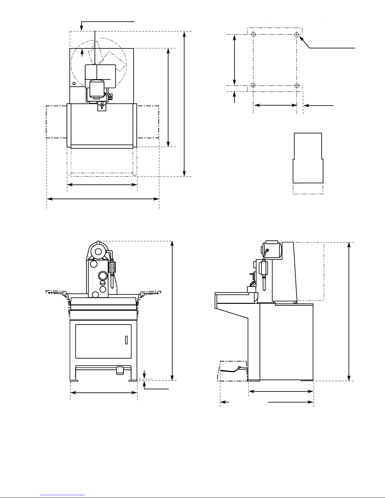
vii
TOP VIEW
FRONT VIEW SIDE VIEW
OUTLINE LAYOUT
Scale:
1 mm = 48 mm
1/4 in. = 1 ft.
Weight Installed:
Approximately 287 kg. (630 lbs.) including coolant.
Floor Loading:
Less than 739 kg/sm (151 lbs/sf).
152 mm (6 in.)
WITH DOOR OPEN
1524 mm (60 in.)
WITH PAN EXTENDED
1054 mm 41.5 in.)
WITH PAN RETRACTED
813 mm
(32 in.)
730 mm
(28.75 in.)
700 mm
(27.5 in.)
6,5 mm
(0.25 in.)
1600 mm
(63 in.)
FRONT
587,4 mm
(23.125 in.)
72 mm
(2.8125 in.)
15,9 mm (0.625 in.)
DIA. (4 HOLES)
533,4 mm
(21 in.)
83 mm
(3.25 in.)
ADJUSTABLE
1575 mm
(62 in.)
1250 mm
(49 in.)
OPTIONAL
WORK TRAY
OPTIONAL
WORK TRAY
Page 8

NOTES
viii
Page 9
PURPOSE
This Section is designed to aid user in unpacking,
inspecting, and installing Sunnen®Honing Machine,
model LBB-1660. Hereafter, referred to as Machine
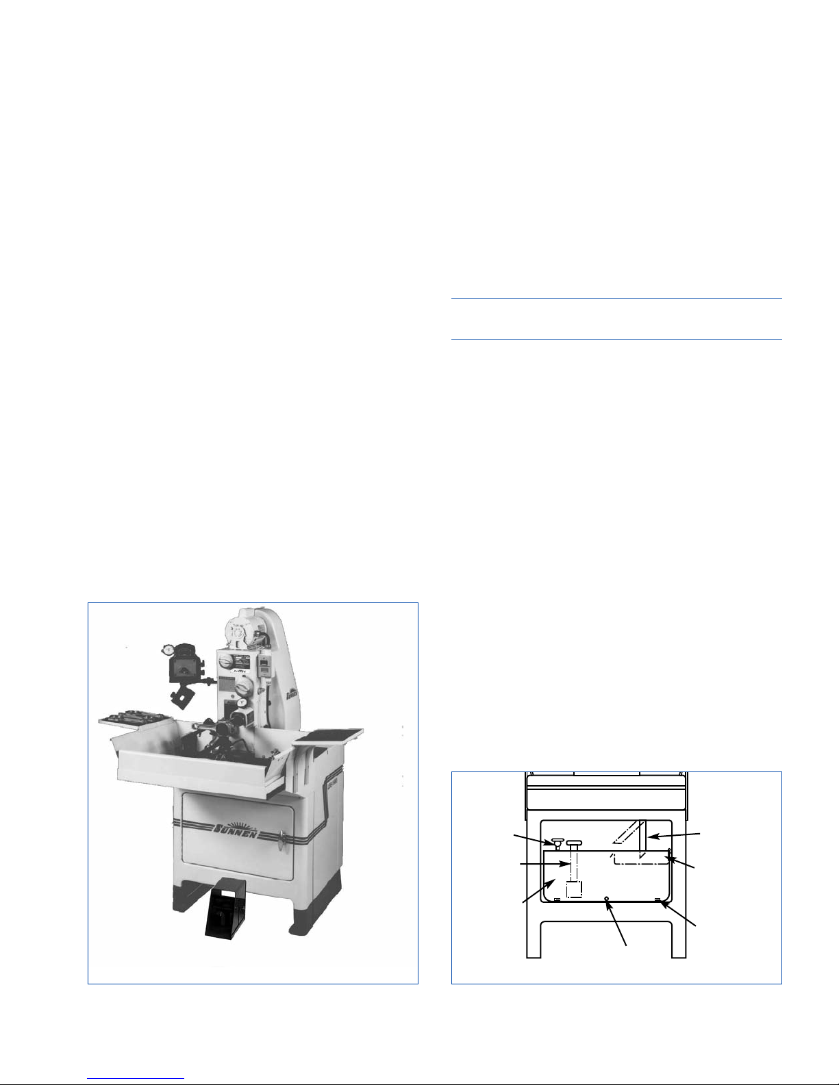
(see Figure 1-1).
TOOLS & MATERIALS
The following tools and materials are required for
unpacking and installing machine:
Wire Cutters/Strippers Knife
Screw Driver (Std. nose) Hammer
Slip-Joint Pliers Crow Bar
Open End Wrenches Tin Strips
Cleaning Solvent Hex Wrenches
INSTALLATION
Read following instructions carefully and thoroughly
before unpacking, inspecting and installing Machine.
All references to right and left in these instructions
are, unless otherwise noted, as seen by operator as
one looks at front of Machine.
1. Remove top and front of shipping carton by
cutting along edges.
2. Remove Components shipped inside carton.
Then, unbolt and remove Machine.
3. Inspect Machine and Components for dents,
scratches, or damage resulting from improper handling,
by carrier. If damage is evident, immediately file a
claim with carrier.
4. Place Machine in desired location.
5. Level Machine in both left to right and front to
back directions. Shim as required.
NOTE: For permanent installation, secure Machine's
Support Feet to Floor with Four (4) Fasteners.
6. Open access Door on front of Machine.
7. Remove Reservoir Retainers, by removing two
(2) Screws
(see Figure 1-2).
8. Remove and discard cardboard packing.
9. Push Drain Pipe to left and up.
10. Loosen Clamp Knob and move Pump back to
loosen oil pump Belt. Then slip belt off pulley.
11. Pull Reservoir out far enough to remove all
packing paper and tape from reservoir.
12. Remove packing material and tape from
Settlement Tray, and install tray in Reservoir.
13. Push Reservoir all way in and install Reservoir
Retainers, removed in step 7.
14. Reinstall oil pump Belt on pulley, removed in
step 10.
15. Pull Pump forward until belt is under tension;
then tighten Clamp Knob.
16. Pull Drain Pipe down and to right.
17. Close access Door to Reservoir.
18. Remove paper and tape from Work Tray.
SECTION 1
INSTALLATION
1
FIGURE 1-1, Precision Honing Machine
LEFT
RIGHT
FRONT
FIGURE 1-2, Coolant Reservoir
CLAMP
KNOB
RESERVOIR
RETAINER
RESERVOIR
DRAIN
PLUG
SETTLEMENT
TRAY
PUMP
DRAIN PIPE
Page 10
FOOT PEDAL
The following instructions cover installation of Foot
Pedal Assembly on Sunnen Pedestal Honing
Machines. To install Foot Pedal Assembly, proceed
as follows
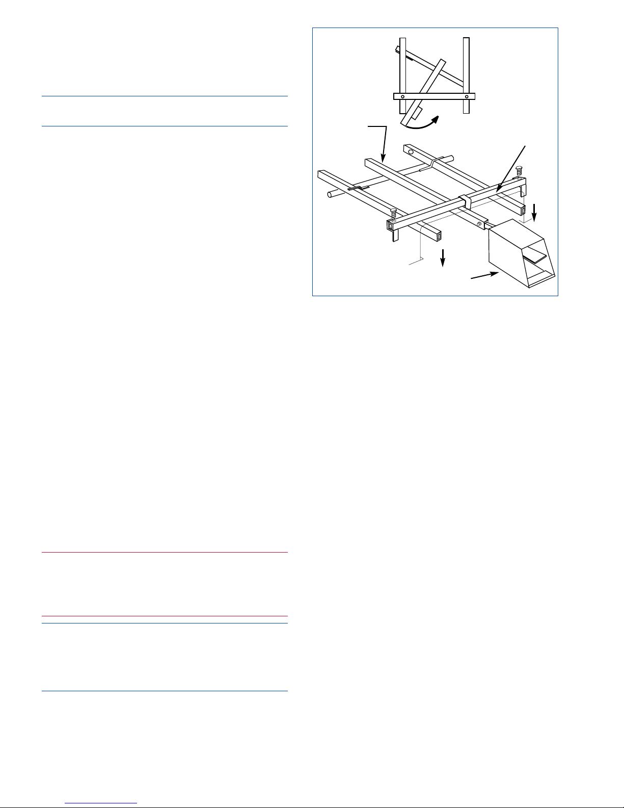
(see Figure 1-3):
NOTE: DO NOT attempt to fork machine with
Pedal Tube Assembly and Pedal Assembly installed.
1. Loosen Socket Head Screw (1/4 in. Hex Wrench)
securing Extension Bar to Cross Bar, and slide
Extension Bar out of Cross Bar.
2. Slide Cross Bar under machine so U-Shade Hook on
end of Bar engages Machine’s Foot Pedal Extension
Bars. Slide Bar in at an angle; engage one side, then
straighten out Bar to engage other side.
3. Slide Cross Bar back and hook over Machine’s
Cross Arm.
4. Remove Foot Pedal from Accessory Pack.
5. Lay Foot Pedal Assembly (Extension Bar) on its side.
6. Slide Foot Pedal over Cross Arm on Extension Bar
and tighten Socket Head Screw (1/4 in. Hex Wrench).
7. Slide Extension Bar into Cross Bar and tighten
Socket Head Screw (1/4 in. Hex Wrench).
ELECTRICAL GROUNDING
In event of a malfunction or breakdown, grounding
provides a path of least resistance for electric
current to reduce risk of electric shock. Single-phase
machines are equipped with an electric cord having
an equipment-grounding conductor and a grounding
plug. Plug must be plugged into a matching outlet
that is properly installed and grounded in accordance
with all local codes and ordinances. For the 120V
unit, a temporary adapter may be used to connect
this plug to a 2-pole receptacle, if a properly grounded
outlet is not available. Adapter should ONLY be used
until a properly grounded outlet can be installed by a
qualified electrician. In the case of the 230V machine,
No adapter should be used with this unit.
WARNING
An arc flash hazard exists. follow safe work practices
and wear appropriate personal protective equipment.
Follow proper lockout / tagout procedures.
Failure to
comply can result in death or injury.
CAUTION
Do not modify plug provided on single-phase
machines; if it will not fit outlet, have a proper outlet
installed by a qualified electrician or obtain the proper
electrical cord from a certified electrical vendor.
Make sure the electrical plug supplied with your
unit matches the proper voltage outlet for your local
area. If the electrical cord supplied does not match
that outlet, consult with a qualified electrician to
obtain the proper cord and plug. Have a qualified
electrician wire the cord to the machine using the
provided wire diagram as a reference. Also, never
remove the grounding pin from the supplied plug. If
necessary, use a proper adapter to assure adequate
grounding.
Improper connection of equipment-grounding
conductor can result in a risk of electric shock.
Conductor with insulation having an outer surface
that is green with or without yellow stripes is a
grounding conductor. If repair or replacement of
electric cord or plug is necessary, do not connect
equipment-grounding conductor to a live terminal.
Check with a qualified electrician or service-man if
grounding instructions are not completely understood,
or if in doubt as to whether machine is properly
grounded.
Use only 3-wire extension cords that have 3-prong
grounding plugs and 3-pole receptacles that accept
single-phase machine's plug.
Repair or replace damaged or worn cords immediately.
ELECTRICAL
Electrical Supply Cord comes installed on most
single-phase Machines. The electrical data plate
provides helpful data including maximum current
requirements and wiring diagram number for your
machine.
If Electrical Supply Cord is not supplied or in case
of three-phase machines, a cord will need to be
connect as follows
(see Figure 1-4):
2
FIGURE 1-3, Pedal Assembly
PEDAL
TUBE
ASSEMBLY
PEDAL
YOKE
PEDAL
ASSEMBLY
Page 11
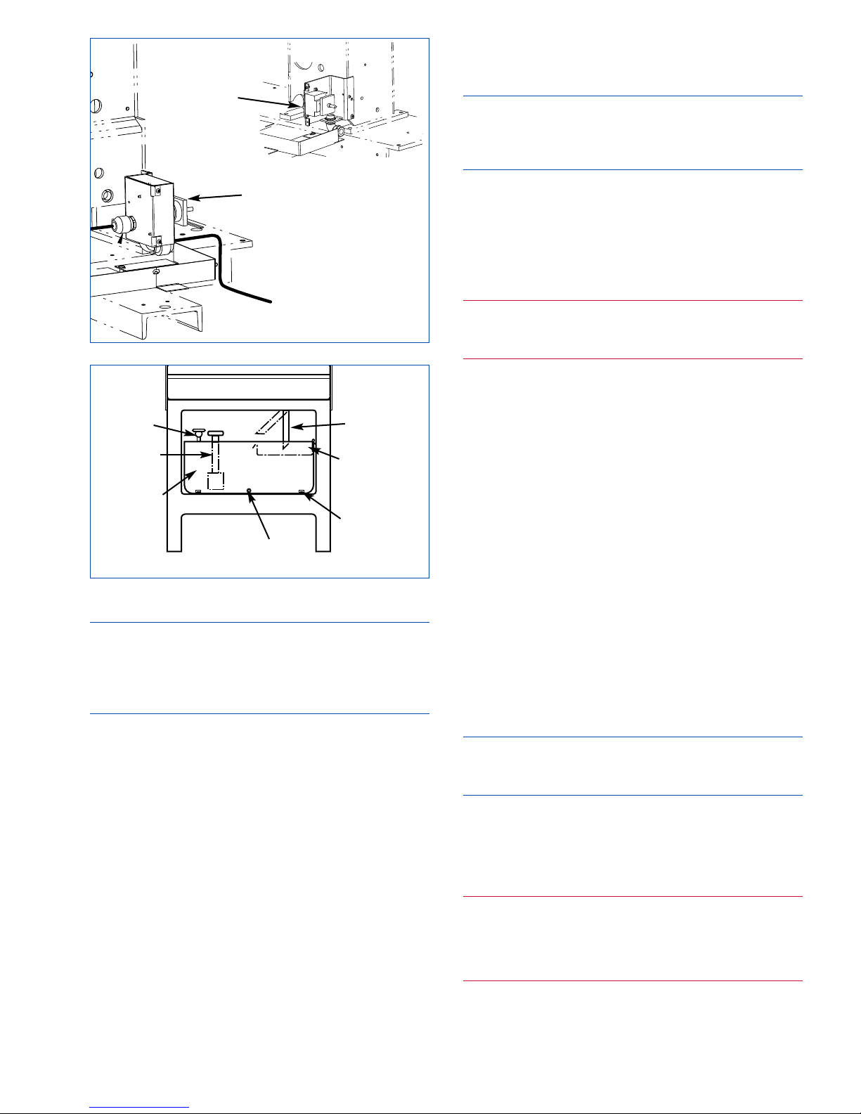
NOTE: 110/230V machines require a #10/4, Type
SO, 600 Volts (5,3mm
2
) electrical supply cord.
460V machines require a #12/4, Type SO, 600 Volts
(3,3mm2) electrical supply cord (see Specifications
at front of manual).
1. TURN OFF all electrical power to machine.
2. Turn OFF Disconnect Switch; loosen Safety Pin
and raise Belt Cover Latch.
3. Open Belt Guard.
3. Insert Electrical Supply Cord into Disconnect
Box through Cord Connector under Box.
5. Strip 250 mm (10 in) off cable's outer jacket
6. Strip 10 mm (3/8 in) of insulation from each wire.
7. Connect green wire (electrical supply cord) to
Ground Lug on bracket.
8. Connect other wires (electrical supply cord) to
Disconnect Block as noted on block.
9. Close Belt Guard, reengage Belt Cover Latch,
and tighten safety Pin.
10. Turn ON Disconnect Switch.
11. TURN ON all machine electrical power.
COOLANT
Fill Coolant Reservoir with Sunnen Honing Oil or
Water-Based Coolant as follows
(see Figure 1-5):
NOTE: Maximum capacity of Reservoir is 19
gallons (72 liters) without filter; or 22 gallons (83
liters) with filter. Minimum capacity of 8 gallons (30
liters ) is needed for proper pump operation.
1. Open Door on front of Machine.
2. Remove Settlement Tray from Reservoir.
3. Pull Work Tray to fully extended position and
pour coolant into Work Tray; or pump/pour coolant
into Reservoir.
4. Replace Settlement Tray and close door.
WARNING
Clean Coolant spills. Coolant can be slick and can
provide a personal fall hazard.
OPERATIONAL CHECK
Read Section 2 and 3 thoroughly and carefully
before performing Operational Check.
1. Turn ON power at Main Power Disconnect.
2. Direct Coolant Nozzles downward, toward
anti-splash pad.
3. Push START Button to start Coolant Pump
Motor. Wait a few seconds for coolant pressure to
build up.
4. With Coolant Nozzles directed downward; open
Total Volume Valve, on Flow Control Manifold, by
turning Valve counterclockwise.
5. Adjust coolant flow to each of nozzles with
Individual Nozzle Control Valves.
6. Check that motors and spindle are operating
properly. With machine turned on; slowly press pedal
down. Check that spindle rotates counterclockwise as
shown by arrow on spindle nose.
NOTE: Rotation of Spindle Shaft should be
counterclockwise, as viewed from output end of
spindle drive motor.
● If rotation is incorrect (spindle rotates clockwise):
On single-phase machine, follow instructions on
inside of motor terminal box cover plate to reverse
motor rotation. On 3-phase machines, reverse any
two of three wires connected to Disconnect Switch.
WARNING
An arc flash hazard exists. follow safe work practices
and wear appropriate personal protective equipment.
Follow proper lockout / tagout procedures.
Failure to
comply can result in death or injury.
7. Push STOP Button.
8. Turn OFF power at Main Power Disconnect.
3
FIGURE 1-5, Coolant Reservoir
CLAMP
KNOB
RESERVOIR
RETAINER
RESERVOIR
DRAIN
PLUG
SETTLEMENT
TRAY
PUMP
DRAIN PIPE
RE-ROUTE ORIGINAL
POWER CABLE FROM
BOX TO POWER SOURCE
FIGURE 1-4, Electrical Connection
ROUTE POWER CORD
FROM BOX TO POWER
SOURCE
DISCONNECT
BOX
DISCONNECT
BLOCK
Page 12
4
9. Close Total Volume and Individual Control
Valves on Flow Control Manifold.
NOTE: Total Volume Valve may now be used to
shut entire supply off, leaving individual settings
unchanged.
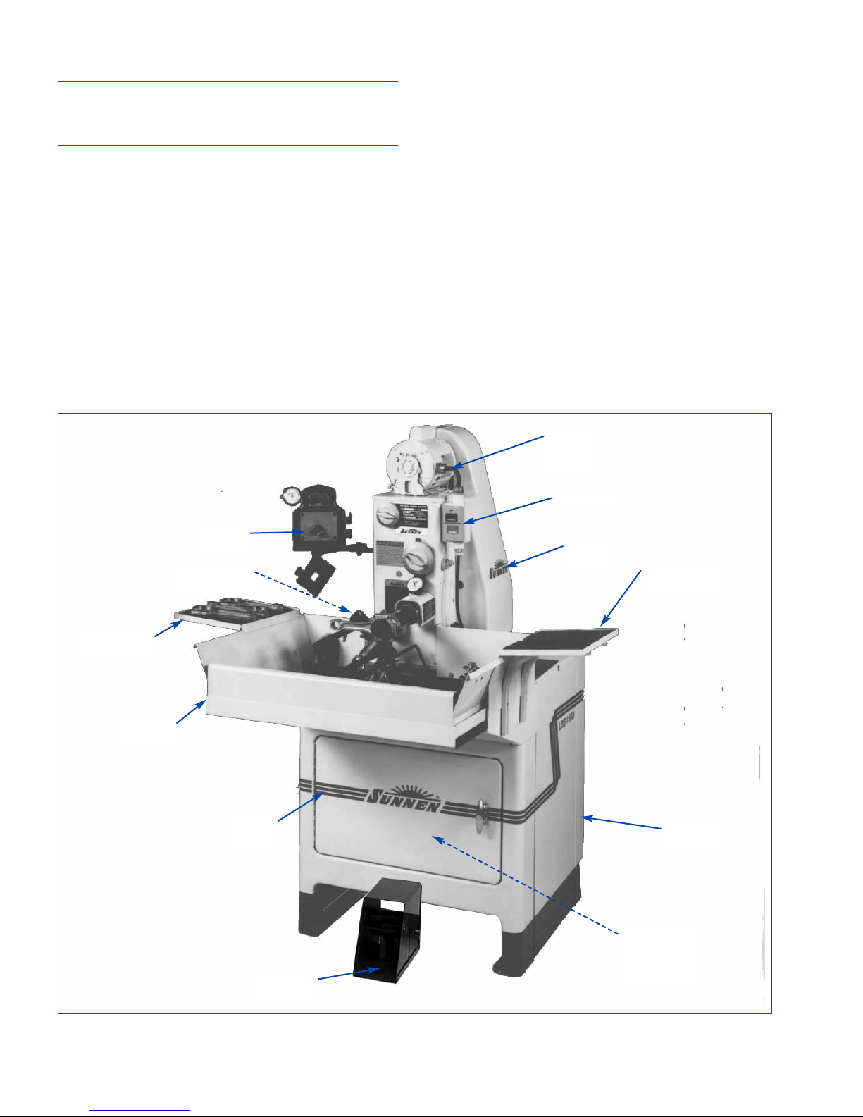
FIGURE 2-1, Major Components
CONTROLS
WORK TRAY
(Optional)
GAGE
(Optional)
WORK TRAY
(Optional)
MOVABLE
TRAY
ACCESS
DOOR
PEDAL
ASSEMBLY
BASE
ASSEMBLY
BELT
GUARD
SPINDLE
DRIVE
MOTOR
LITERATURE
POCKET
(Located on
inside of Door)
DISCONNECT
SWITCH
Page 13
GENERAL
Consult this section when preparing Machine for
operation.
MAJOR COMPONENTS
For location of major components on machine see
Figure 2-1
. (All directional references are as viewing
assembly from left side of machine.)
1. BASE ASSEMBLY. Base Assembly consists of
following components
(refer to Figure 2-1):
Machine Base. Honing Machine is equipped with a
heavy base to support Hone Head Assembly and
houses operating components.
Access Doors are located on top and front of machine to
provide easy access to machine operating components.
Literature Pocket is located inside front access
Door. Used for storage of literature.
Movable Tray is located on top front of machine. It
adjusts to accommodate honing units and workpieces of varying lengths.
Machine is shown with two (2) optional
Work Trays
located to left and right of Movable Tray.
Adjustable Work Support is located in Movable Tray.
It assures more accurate results when honing and
help prevents operator fatigue by carrying weight of
workpiece and absorbing honing torque. Especially
useful for honing large or bulky parts.
Horizontal Adjustment Knobs must be loosened to
move Work Support to left or right. Four tapped holes
allow you to place Support in any horizontal position.
Universal Adjustment Handle loosens to position
Work Support vertically and horizontally.
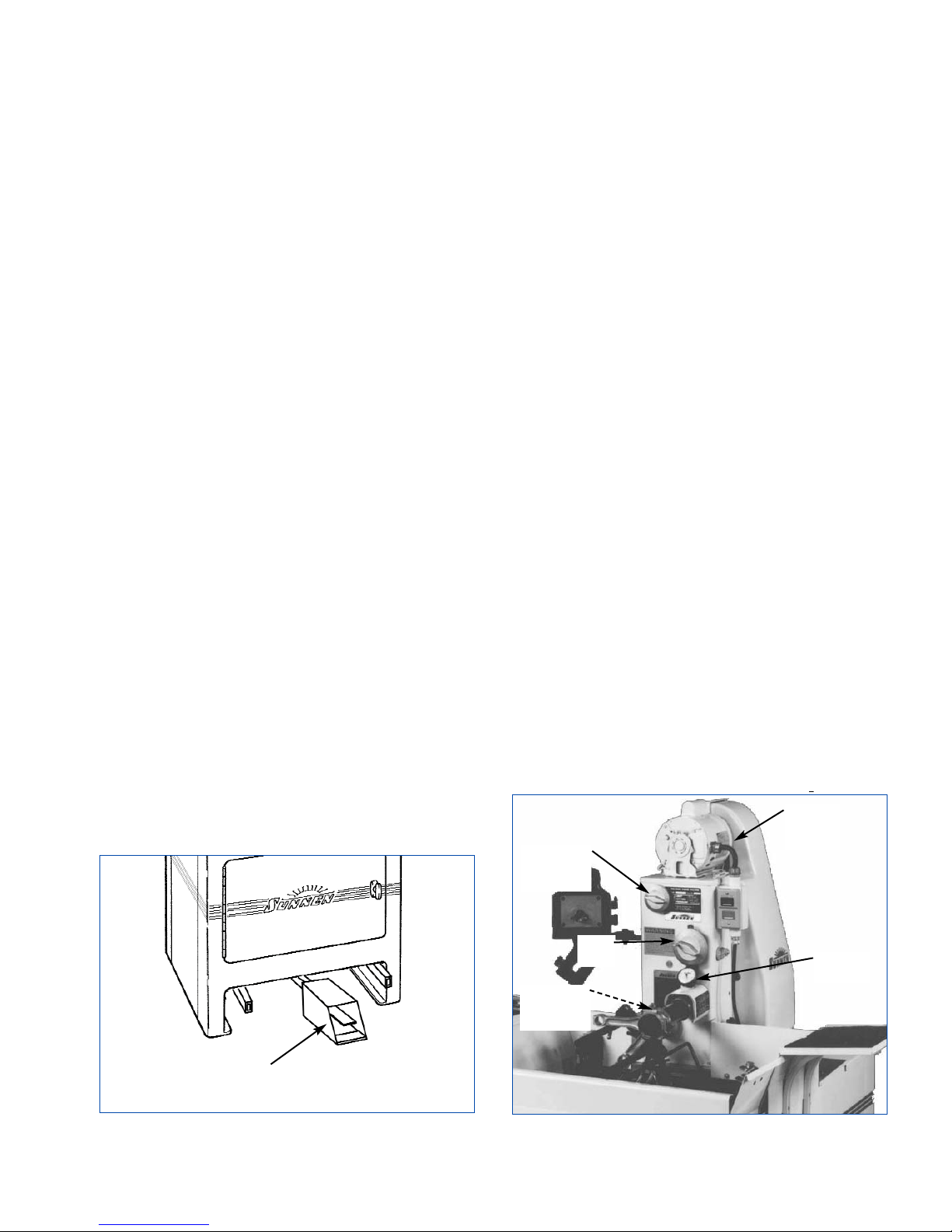
2. PEDAL ASSEMBLY. Pedal Assembly is located
on front and inside of Machine Base
(see Figure
2-2)
. When depressed, assembly starts spindle drive
motor, stroking drive motor, and expands stones.
Assembly consist of following components:
Adjustable
Pedal Bar & Pedal is located on lower
front of machine. Both Bar and Pedal are adjustable
to accommodate individual operator.
Pedal Guard covers Pedal, preventing pedal from
inadvertently being depress during setup and
machine spindle rotating.
3. HONE HEAD ASSEMBLY Hone Head Assembly
consist of following components
(see Figure 2-3):
Disconnect Switch is located on left side of Belt
Guard. Switch shuts off power to Hone Head Drive
Pulley.
Light Cutting Pressure Control Dial is located on
top left of assembly. It is used to adjust cutting
pressure of honing stone in small diameter bores, in
soft materials, for rough bores or for fine finishes.
Use in conjunction with Feed Dial and Honing Dial
to ensure maximum efficiency.
Feed Dial is located on top left of assembly below
Light Pressure Control Dial. Setting of this dial limits
maximum honing stone expansion, and allows honing
stone to feed out automatically during honing operation
until preset point is reached.
Honing Dial is located on front center of assembly.
It measures expansion of stone as wedge moves
forward, and indicates that maximum stone expansion point has been reached when needle reads "0".
Works in conjunction with Feed Dial. With workpiece on honing unit and Feed Dial set for desired
stock removal, Honing Dial needle shows amount of
stock to be removed.
5
SECTION 2
PREPARING FOR OPERATION
FIGURE 2-2, Base Assembly FIGURE 2-3, Hone Head Assembly
PEDAL
SPINDLE
DRIVE
MOTOR
LIGHT
PRESSURE
CONTROL
FEED
DIAL
HEAVY-
PRESSURE
CONTROL
HONING
DIAL
Page 14
6
Heavy Cutting Pressure Control Dial is located on
lower left of assembly. It is used to adjust cutting
pressure of honing stone where heavy stock removal
is required. Use in conjunction with Feed Dial and
Honing Dial to ensure maximum efficiency.
Spindle Drive Motor is located on top of assembly.
It supplies power for honing operation.
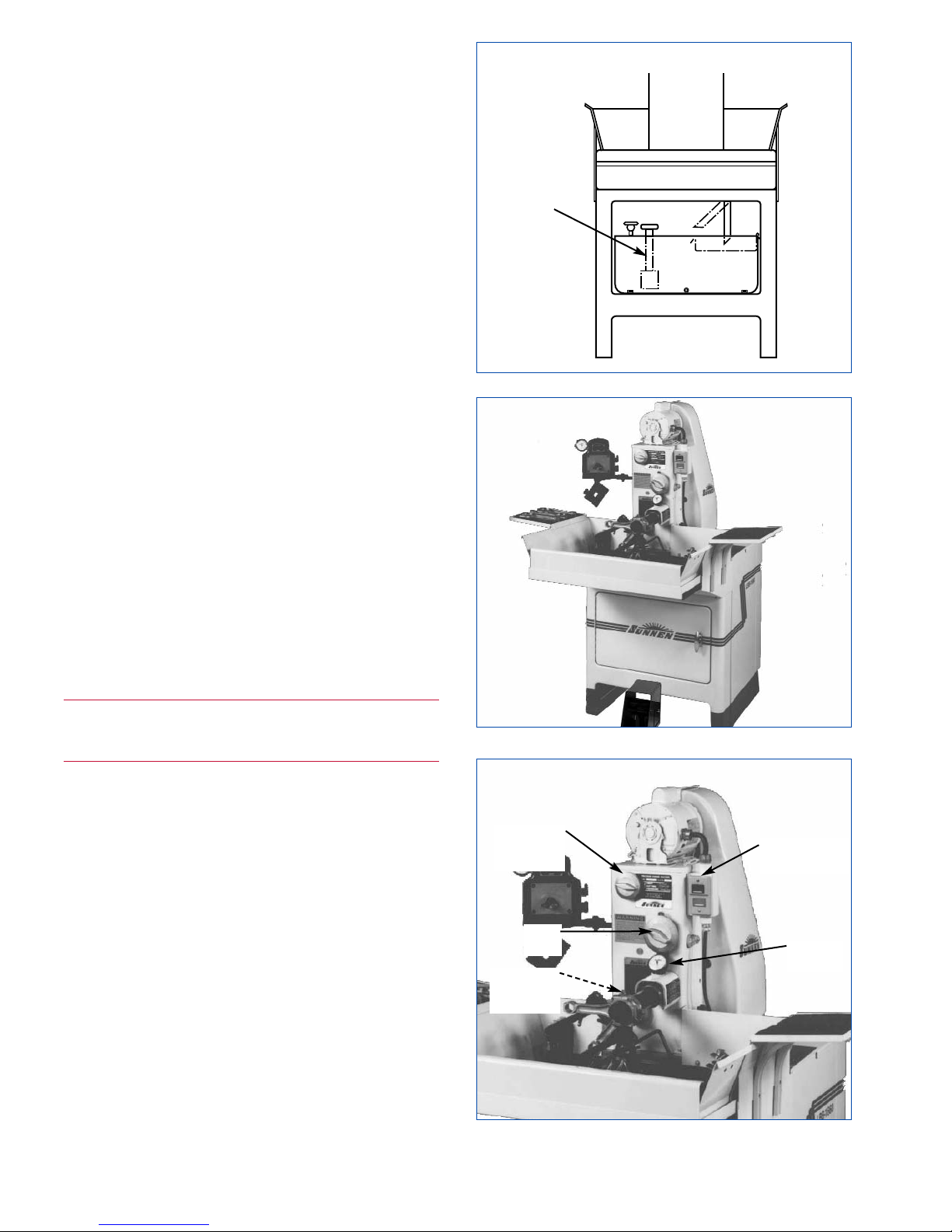
4. COOLANT PUMP SYSTEM. Applies coolant to
workpiece and mandrel. Three independently controlled
nozzles are easily positioned to assure an even flow of
coolant through workpiece being honed and over full
length of mandrel. Two nozzles are used to feed
coolant to each end of mandrel. The third may be
used to feed additional coolant to either end of
workpiece, for externally cooling workpiece or for
flushing workpiece before gaging. Coolant Pump
System is located inside top left of machine
(see
Figure 2-4)
. It consists of following components:
Centrifugal Coolant Pump is located inside coolant
reservoir and is driven by spindle motor.
Coolant Flow Control Manifold is located on left
front of machine. It provides independent regulation
of coolant flow to each
Coolant Nozzle through
Total Volume Control Valve and Individual Coolant
Nozzle Control Valves
. Total volume valve is used
to turn on and off supply of coolant, eliminating
readjustment of individual coolant nozzle control
valve setting.
Coolant Nozzles attaches to Coolant Support Arm
located on front of machine in Movable Tray.
Nozzles supply coolant to workpiece and mandrel.
Three independently controlled coolant nozzles are
easily positioned to assure an even flow of coolant
through workpiece and over full length of mandrel.
WARNING
Clean Coolant spills. Coolant can be slick and can
provide a personal fall hazard.
6. ELECTRICAL COMPONENTS Sunnen Honing
Machine is available in 110/230 Volt, single phase,
60 Hz.; or 220//380/440 Volt, 50 Hz, 3 Phase. Its
major components are as follows
(see Figure 2-5):
Operator
Controls are located on right front of Hone
Head Assembly.
Main Power Disconnect is located on left side of
Belt Guard. Electrical power to machine is
controlled by Main Power Disconnect.
7. ACCESSORIES The following items are supplied
as standard equipment with your machine:
Hex Key Wrenches, Metric Wrenches, and T-Wrench.
MAN-700 Diamond Dresser. Used to break glaze on
aluminum oxide and silicon carbide honing stones.
Manual Torque Support. Adjustable support used to
absorb torque from holding fixture (or workpiece)
when honing manually. Manual Torque Support
Arm. Used to hold Manual Torque Support when
manually honing.
FIGURE 2-4, Coolant Pump Assembly
COOLANT
PUMP
FIGURE 2-5, Electrical Components
FIGURE 2-6, Controls
CONTROLS
(START/STOP)
LIGHT
PRESSURE
CONTROL
FEED
DIAL
HEAVY-
PRESSURE
CONTROL
HONING
DIAL
Page 15
10. OPTIONS. The following is a list of optional
equipment available for machine:
Adjustable Stroking Stop mount on Work Support
and limits honing stroke; especially useful when
honing blind holes.
Gage Mount, Model MB-2370A. Mounts on left
front of machine and is used to rest Sunnen AG/PG
Gage on for easy access during honing.
Optional Work Light, model MBC-200, mounts on
top left of Hone Head Assembly and provides glareless illumination for honing and gaging.
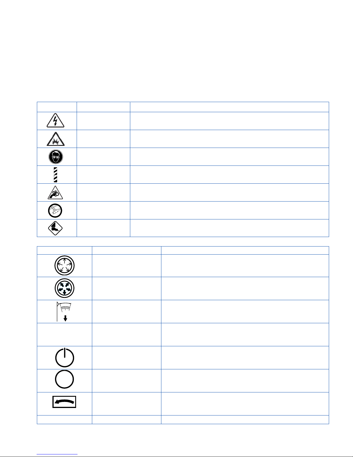
SAFETY SYMBOLS
For a description of safety symbols used on this
machine,
refer to Table 2-1.
MACHINE CONTROLS
For location and function of machine controls refer
to Figure 2-6 and Table 2-2
.
7
SYMBOL DESCRIPTION FUNCTION
(Light Cutting Pressure) Adjusts to controls Cutting Pressure of stones against
Rotatory workpiece when honing small diameter bores, soft material,
Dial rough bores, or for fine finishes.
(Heavy Cutting Pressure) Adjusts to controls Cutting Pressure of stones against
Rotatory workpiece for Heavy stock removal.
Dial
(Feed Dial) Expands or retracts stones in honing tools. Setting on
Rotatory dial indicates amount of stone feed per dial graduation
Dial for various tools. (See Stone Expansion Chart.)
(Honing Dial) Indicates amount of stock to be removed from workpiece.
Indicator Used in conjunction with Feed Dial.
Gauge
START Turns ON Power to the Machine. Used in conjunction with
Pushbutton Foot Pedal, STARTS honing cycle.
STOP Turns OFF Power to the Machine. STOPS honing cycle.
Pushbutton)
Rotation Indicates proper direction of rotation.
Arrow
Disconnect Switch Shuts OFF power to Drive Pulley.
TABLE 2-2, Machine/Operator Controls
O
SYMBOL DESCRIPTION FUNCTION
Warning Label Warns that an electrical hazard exists.
Warning Label Warns that an arc flash hazard exists.
Warning Label Warns that safety glasses should be worn at all times when operating
this machine.
Warning Strip Warns that a
physical hazard exists
, and that proper precautions should
be taken.
Caution Label Warns that a finger hazard exists. Do not touch while
Moving Parts stroker is operating.
Warning Warns not to hold workpiece in hand without a torque
Label resisting fixture.
Foot Starts honing cycle and controls stone expansion.
Pedal
TABLE 2-1, Safety Symbols
Page 16
SETUP, GENERAL
To setup the machine for manual stroke honing,
proceed as follow:
1. Turn ON power at Main Power Disconnect.
2. Turn OFF Coolant supply by turning Total
Volume Control Valve fully clockwise.
3. Select Honing Unit from
Sunnen Engine Rebuilding
Equipment Accessories & Supplies Catalog (A-7100)
.
Depending on your part configuration, select a honing
unit type and size most suitable.
Assemble honing unit by using instructions included
with your new mandrel and/or adapter.
4. Select Stone from
Sunnen Engine Rebuilding
Equipment Accessories & Supplies Catalog (A-7100)
.
Determine amount of stock to be removed and number of operations required to getting workpiece to
proper size and surface finish. Many times a three
stone operation is the most economical - that is:
deburring, fast stock removal, and fine finishing. If
deburring is attempted with a stock removal stone,
excessive stone wear will result. If stock removal is
attempted with a deburring stone or finishing stone,
honing time will be excessive.
Use a harder stone to improve stone life. Use a softer
stone to promote freer cutting.
Use a coarse stone for fast stock removal and a fine
stone for finishing. Always use the coarsest stone
that will produce an acceptable surface finish.
Short open bores, blind bores, and tandem bores
may require minor alterations of standard stones.
5. Assemble Honing Unit: According to instructions
packed with Honing Unit.
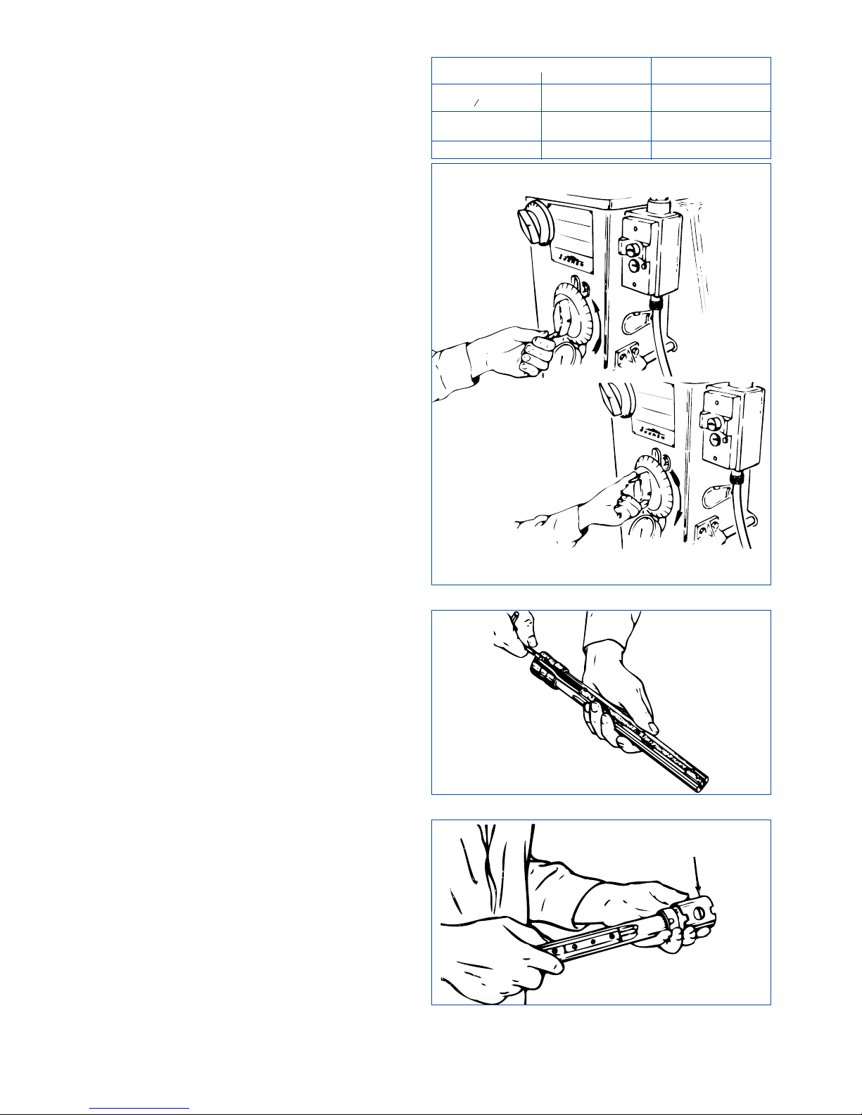
6. Turn Feed Dial counterclockwise until you meet
resistance, then advance dial clockwise about five
turns
(see Figure 2-7).
7. Pull Mandrel Wedge straight back as far as possible,
using hook on end of T-Wrench
(see Figure 2-8).
8. If required, install Spindle Sleeve (LN-570A) on
honing unit. If honing unit fits into spindle very
loosely, use a Spindle Sleeve
(see Figure 2-9).
9. Remove Spindle Cover.
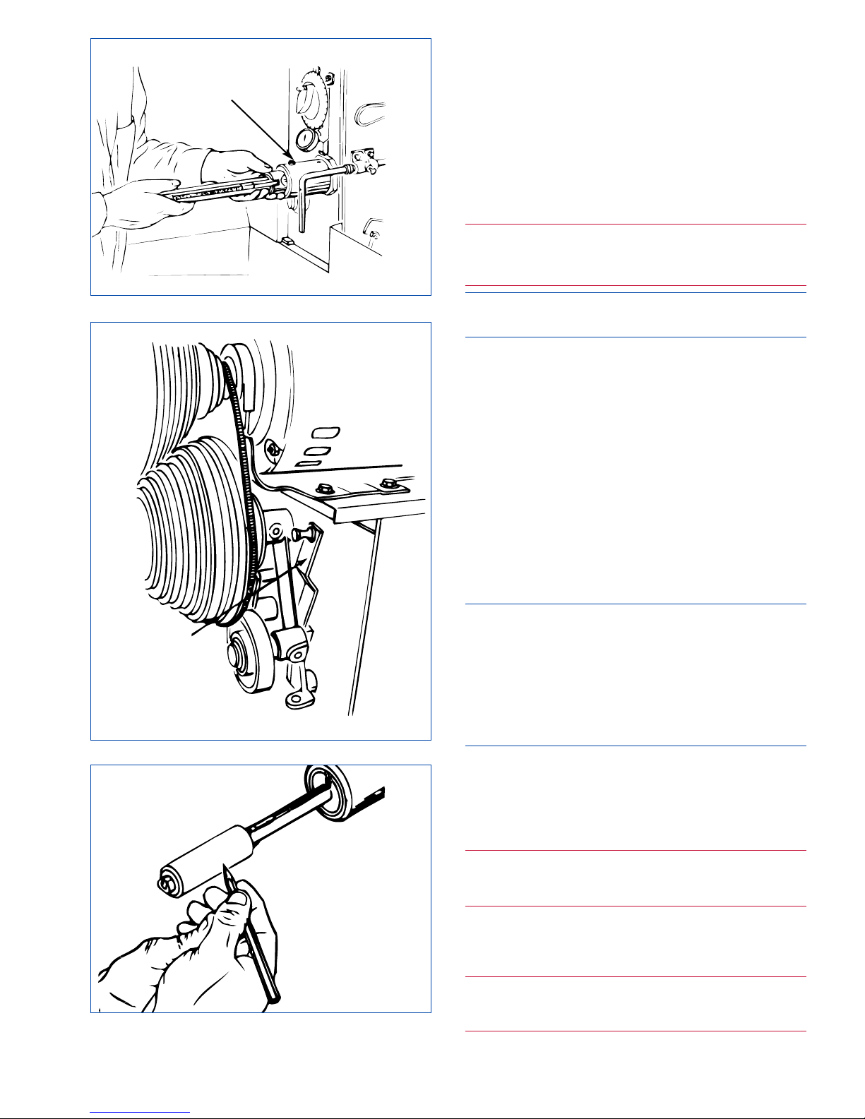
10. With motor off, depress pedal slightly to release
spindle brake and rotate spindle so Large Setscrew
points up (12 o'clock position).
11. With setscrew indentation on honing unit at 9
o'clock position, insert Honing Unit into Spindle
Nose as far as it will go; rotate unit 1/4 turn
clockwise to engage Wedge with Feed Rod; then
push Honing Unit all way in until it bottoms
(see
Figure 2-10)
.
8
FIGURE 2-8, Mandrel Wedge
FIGURE 2-9, Spindle Sleeve
SPINDLE
SLEEVE
FIGURE 2-7, Cutting Pressure Settings
TABLE 2-3, Cutting Pressure Setting
BORE SIZE PRESSURE CONTROL
inches millimeters INITIAL SETTING
.375 to .500
9,5 to 12,7 1
(
3
8 to ½)
.500 to 1.000
12,7 to 25,4 1-½
(½ to 1)
1.000 UP 25,4 UP 2
Page 17
12. Test Wedge hookup by pulling Honing Unit straight
out; if Wedge comes out repeat
steps 9 thru 12. If
wedge is hooked up, it will not allow unit to come
out of spindle.
13. Push unit back into Spindle Nose until it bottoms.
14. Tighten Large Set Screw with T-Wrench.
SPINDLE SPEED
15. With motor OFF, open Belt Guard, by loosening
Safety Latch Pin and raising Belt Cover Latch..
WARNING
Use caution when opening belt guards once power is
shut off; pulleys may still be turning.
NOTE: Machines requires Disconnect Switch to be
turned to Off position before doors can be open.
16. Using Chart on inside of Belt Guard
(see Table 2-3),
position belts for a Spindle Speed of 200 rpm (setup
speed).
17. Pull Idler Handle down
(see Figure 2-11).
18. Move upper V-Belt to 200 rpm position.
19. Move lower V-Belt to Low Speed Range groove.
20. Release Idler Handle by pulling and raising.
21. Close and secure Belt Guard.
22. Set Light Cutting Pressure Control to "1"; and
set Heavy Cutting Pressure Control to "0".
23. Turn Feed Dial counterclockwise to end of range.
MANDREL RUNOUT
NOTE: CR-Series of Honing Units do not require
mandrel runout adjustment. Instead adjust radius of
mandrel as follows: With motor off, depress Pedal
and feed up stone until there is a reading of
approximately 5 on Honing Dial. Loosen shoe
setscrew and adjust mandrel shoes to curative of rod
by tapping rod lightly. Tighten shoe setscrew (do not
overtighten). Go to step 31.
24. Place a concentric Truing Sleeve on Honing Unit,
with an inside diameter the same size as workpiece
to be honed.
25. Depress Pedal and turn Feed Dial clockwise
until Honing Dial reads "5 or 6"; release Pedal.
WARNING
Power to Machine is ON. Machine will begin
operating when START Switch is pressed.
26. Push START Button.
27. Depress Pedal all way down (allow Truing
Sleeve to rotate with Honing Unit).
WARNING
Power to Machine is ON. Keep hands clear of
moving parts.
9
FIGURE 2-10, Install Mandrel
FIGURE 2-12, Mandrel Runout
LARGE
SETSCREW
FIGURE 2-11, Idler Handle
TENSION
RELEASE
LEVER
Page 18
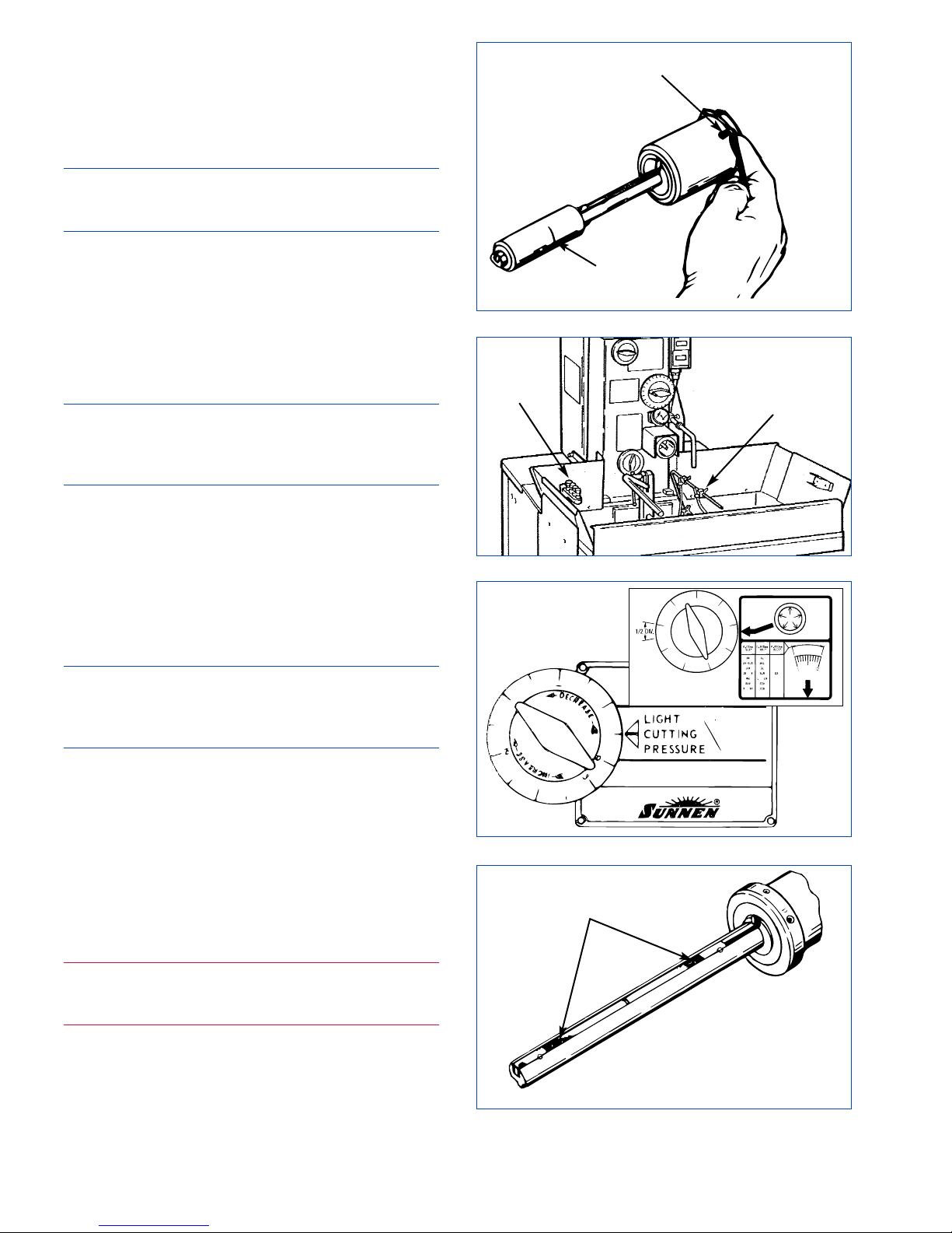
28. Hold marking pencil to front of Sleeve (see
Figure 2-12)
, so it will just touch high points of
sleeve as honing unit is rotating. Repeat on rear of
Sleeve. Resulting marks indicate high point(s).
27. Push STOP Button, but continue to hold pedal
down.
NOTE: A small amount of runout will not affect
accuracy of workpiece. The heavier workpiece/fixture
combination, the less runout can be tolerated.
28. Loosen Numbered Set Screws in Spindle Nose on
same side as pencil marks; and tighten Numbered Set
Screws on opposite side (see Figure 2-13).
29. Wipe Truing Sleeve and repeat
steps 24 thru 29
as required, until minimum runout is obtained.
30. Push STOP Button and remove Truing Sleeve.
31. Press START Button.
CAUTION
Use only undiluted Sunnen Industrial Honing Oil.
This oil will ensure free cutting, reliable stone
performance, and consistent surface finish.
32. Attach and adjust position of Coolant Nozzles
(
see Figure 2-14). Coolant should contact front and
rear of Stone, parallel to mandrel. Adjust Total
Volume and Individual Control Valves.
33. Press STOP Button.
34. Set Light Cutting Pressure Control according to
Table 2-4 or Your Sunnen SMOPS Guide (see
Figure 2-15)
.
NOTE: CR-Series of Honing Units stones and shoes
are self truing; no truing sleeve is furnished or
required. Go to step 49. TRUE IN MANDREL AND
STONE
35. Turn Feed Dial counterclockwise until you feel
resistance.
36. Place a Truing Sleeve or an undersized workpiece
in a torque absorbing workholding fixture.
37. Install Truing Sleeve (in Workholding Fixture)
on mandrel.
38. With motor off, depress Pedal and turn Feed
Dial clockwise until Honing Dial Needle reads "3".
39. Release Pedal.
WARNING
Power to Machine is ON. Machine will begin
operating when START Switch is pressed.
40. Push START Button.
41. Slowly open Total Volume Control Valve on
coolant Flow Control Manifold. Generously apply
Coolant to honing stone, guide shoes, and bore of
Truing Sleeve. Close Total Volume Control Valve.
10
FIGURE 2-15, Light Cutting Pressure
FIGURE 2-14, Coolant
FIGURE 2-13, Numbered Set Screws
NUMBERED
SET SCREW
MARK
FIGURE 2-16, Stone Loading
LOADING
COOLANT
NOZZLE
CONTROL
VALVES
Page 19

42. Center Truing Sleeve over stone and shoes.
43. Grasp Workholding Fixture and Truing Sleeve
firmly and depress Pedal slowly.
CAUTION
Always release Pedal before removing Truing Sleeve
from mandrel.
44. As mandrel begins its rotation, stroke Truing
Sleeve forward and back. Use short strokes at first,
then gradually lengthen stroke until stroke length is
about as long as stone or Truing Sleeve, whichever
is longer. Reverse Truing Sleeve frequently.
If Truing Sleeve is too hard to hold or Honing Dial
Needle moves too rapidly, reduce cutting pressure.
Honing Dial Needle does not move or moves too
slowly, increase cutting pressure.
45. As soon as the truing sleeve and stone become
saturated with oil, adjust Total Volume Control
Valve so that the oil no longer reaches the mandrel
or truing sleeve.
The coolant on Truing Sleeve and stone create a
lapping paste as you are honing; as paste dries out,
add a small amount of Coolant.
Always hone workpiece most where you feel most
pull or resistance.
46. When Honing Dial Needle reaches "0", release
Pedal.
47. Advance Feed Dial four (4) numbers; Depress
Pedal and continue honing until Honing Dial Needle
reaches "0"; then release Pedal.
CAUTION
Always release Pedal before removing Truing Sleeve
from mandrel.
48. Reverse Truing Sleeve frequently. After reversing Truing Sleeve several times stop and examine
stone and shoes.
NOTE: High spots on stones will be loaded (see
Figure 2-16
). Use the LBN-700 Abrasive Stick to
remove high spots on stone. High spots on shoe will
be bright and shiny. A few light strokes with a file
will remove these high spots (use an abrasive stick
like the LBN-700 to true hardened steel guide shoes).
49. Repeat above operation, until at least a line contact
is achieved on each shoe and on stone.
NOTE: The objective of truing the mandrel and stone
is to make the shoes and stones parallel. However,
when honing to very close tolerances or when honing
holes with keyways, the honing unit should also be
trued to the finish bore diameter as closely as possible.
When truing Keyway (Y-type) mandrels, refer to
instruction sheet packed with mandrel. Keyway
mandrels should be fully radiused to within .005"
(0.13 mm) of workpiece finish bore size.
50. When mandrel is trued in, push STOP Button.
51. Replace Spindle Cover.
SPINDLE SPEED
52. Open Belt Guard, by loosening Safety Latch Pin
and raising Belt Cover Latch.
NOTE: Turn Disconnect Switch on left side of Belt
Guard to OFF position, then open doors.
53. Using Chart on inside of Belt Guard, select Spindle
Speed according to bore diameter (see Table 2-5).
If the part is heavy enough to exert a considerable
force on honing unit/mandrel, use a slower speed
than shown. For external honing, use two speeds
slower than shown
CAUTION
Extra long mandrels should be run at a slower speed
than shown.
54. With motor OFF, pull Idler Handle down.
55. Move V-Belt to appropriate groove. Use 320 rpm
for most passenger car and light truck rods in 1.4 to
2.6 in (36-66 mm) diameter range. Use 250 rpm for
large truck rods over 2.6 in (66 mm) in diameter.
11
TABLE 2-4, Cutting Pressure Setting
BORE SIZE PRESSURE CONTROL
inches millimeters INITIAL SETTING
.375 to .500
9,5 to 12,7 1
(
3
8 to ½)
.500 to 1.000
12,7 to 25,4 1-½
(½ to 1)
1.000 UP 25,4 UP 2
TABLE 2-5, Spindle Speed Selection
WORK DIAMETER SPINDLE
inches millimeters SPEED
UNDER 1.250 UNDER 32 640
1.250-1.625 32-41 500
1.625 - 2.000 41-51 400
2.000 - 2.500 51-64 320
2.500 - 3.250 64-83 250
OVER 3.250 OVER 18 200
UNDER .500 UNDER 13 640
.750 18 500
.875 22 400
1.000 25 320
1.500 38 250
OVER 2.000 OVER 51 200
CAUTION: Power MUST be OFF when Guard is open.
Page 20

For easiest belt shifting, always move the belt from
the larger to the-smaller diameter groove first.
56. Release Idler Handle by pulling and raising.
57. Close and secure Belt Guard.
58. Set Light Cutting Pressure Control according to
bore diameter (
refer to Table 2-4.or your Sunnen
SMOPS Guide
). Always start a new honing job with
light pressure. Increase pressure as needed.
59. Set Heavy Cutting Pressure Control to "0". Heavy
Cutting Pressure Control is always set to zero when
using Light Cutting Pressure Control.
Heavy Cutting Pressure Control is used for fast
stock removal in larger bores.
MANUAL STROKE HONING
Refer to this step when setting up your Machine for
MANUAL STROKE HONING.
1. Position Work Support. Support should be placed
approximately under center of gravity of work if the
part is very heavy, other-wise position the bar as far
from the mandrel as the part or holding fixture will
allow. Position Work Support as close as possible to
end of Rod without locating on curved portion of rod.
CAUTION
All workpieces MUST be in a Holding Fixture to
avoid injury and damage to machine (see Sunnen
Data Files 107 and 108 for fixturing suggestions).
2. Place workpiece in Holding Fixture.
3. Install workpiece on mandrel.
4. If used, adjust optional stroking stop. Measure
length of bore to be honed and measure length of
honing stone. The longer of two is maximum stroke
length. If workpiece have large counterbores or large
overhangs, shorten stroke length to gain stability.
NOTE: For blind holes, stroke length should be
bore length (including relief) minus 1/2 stone length.
Shorten stroke if stability becomes a problem.
For tandems using a solid line of stones, the stroke
length is equal to the total stone length minus the
tandem distance. For tandems using separated
tandem stones; the stroke length is equal to the
tandem land length or individual stone length,
whichever is longer.
5. Setup is complete, proceed to
Section 3, Operation.
12
Page 21
GENERAL
This section describes a step-by-step operating
procedure for Machine.
• Prior to starting Machine, Operator shall ensure:
• All prerequisites described in sections
1 and 2 are
complete.
• All personnel are clear of machine.
SAFETY PRECAUTIONS
The following precautions should be followed to
ensure maximum safety of personnel while working
on or around Machine.
WARNING
Do not wear cotton or heavy gloves while operating this
equipment! If gloves must be worn, wear only the tearaway type.
Use caution when opening belt guards once power is
shut off; pulleys may still be turning as motor coast to a
stop.
An arc flash hazard exists. follow safe work practices
and wear appropriate personal protective
equipment.
Follow proper lockout/tagout procedures.
Failure to
comply can result in death or injury.
• Ensure all guards are in place before operating.
• Ensure area is clear of other personnel before
operating machine.
• Keep machine clear of tools or other foreign objects.
• Wear proper safety items such as, safety glasses,
gloves, non-slip safety shoes and other personal
safety equipment as necessary or required.
• DO NOT wear loose clothing or jewelry while
working on or around machine.
• Keep area around machine free of paper, oil, water
and all other debris at all times.
• When lifting part or tooling use proper lifting
procedures. DO NOT overreach; keep proper footing and balance at all times.
• Turn OFF electrical power at Disconnect Switch on
side of Belt Guard.
• Turn OFF electrical power at Disconnect Switch,
when performing maintenance on, or cleaning of
Electrical Components.
• Clear area of excessive lubricant or lubricant spills.
Coolant can be slick.
• DO NOT adjust stroke length while honing.
• KEEP hands clear of all moving parts. Stay clear
of all moving parts.
•
Remove keys and wrenches from machine before
honing.
• DO NOT hand hold parts while honing. To pre-
vent personal injury and machine damage, DO NOT
hone without installing part in workholding fixture.
• To avoid personal injury, allow spindle and stroking
arm to come to a complete stop before removing part.
• Keep all visitors a safe distance from work area.
• DO NOT use in dangerous environment. DO NOT
use machines in damp or wet locations, or expose
them to rain. Keep work area well lighted.
OPERATING HINTS
In addition to pistons, con rods and king pins
covered here, Machine can be use to hone other
jobs: Including small bore engines, air compressor
cylinders, starter and generator bushings, and many
more jobs.
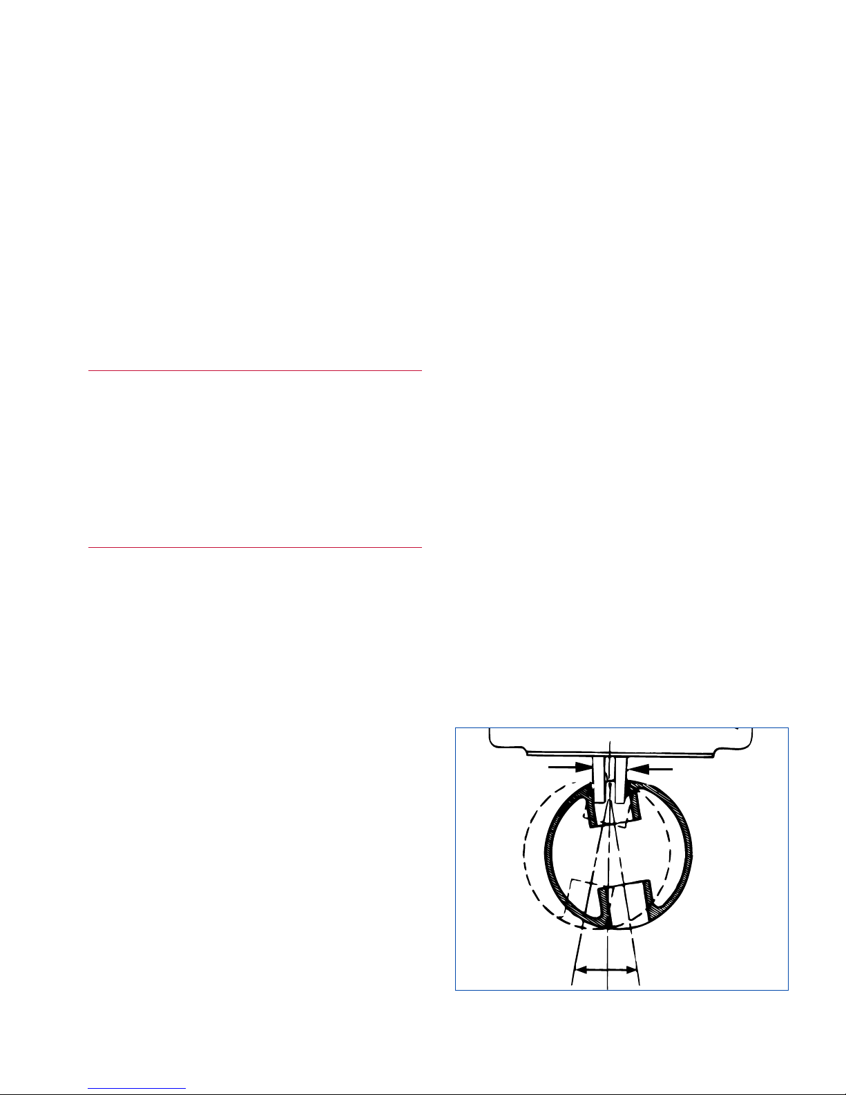
1. PISTONS: Hone pistons as outlined under Manual
and Power Stroked Honing, with following exceptions:
Gaging: Hold piston lightly with thumb edge of
skirt and fingers under crown
(see Figure 3-1).
Slip piston first over Adjustable Finger point, then
slide it over Size Indicating Finger point. Allow
piston to hang from centralizer point, but do not
allow it to contact gage face. Make certain that
gaging and centralizer points clear oil holes and
grooves in bushing or pin boss. Hold piston level
and rock it right to left as shown, to obtain
maximum gage indicator reading (maximum
counterclockwise movement of indicator hand).
Appendix C gives suggested pin clearance guidelines;
refer to manufacturer specifications for recommended
pin clearance for your particular application.
13
SECTION 3
SETUP & OPERATION
IL-2490
FIGURE 3-1, Piston
Page 22
Honing: Use a piston type hone unit. Set Heavy
Cutting Pressure Dial to "0". For rough honing set
Light Cutting Pressure Dial between "2 to 2-1/2";
and for finish honing set Light Cutting Pressure
Dial to "1-1/2".
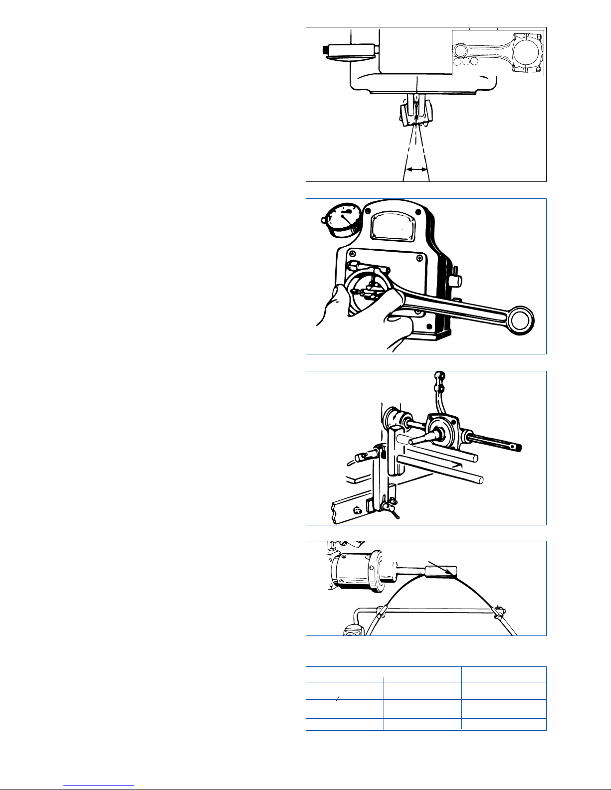
2. PIN END OF CON RODS: Con rods are honed
in manner outlined under Manual and Power
Stroked Honing, with following exceptions:
Gaging: Hang rod freely from gage centralizer point
(see Figure 3-2). Do not touch face of gage with
rod. Rock rod from side to side to determine bore
size by minimum indicator reading.
Honing: Always start and stop stroking in middle of
stone. Use a con rod type hone unit. Set Heavy
Cutting Pressure Dial to "0". For rough honing set
Light Cutting Pressure Dial between "2-1/2 to 3";
and for finish honing set Light Cutting Pressure
Dial to "2".
3. CON RODS WITH PRESS FIT: Most engines
require pin to have a press fit in rod, and exact
interference fit is necessary. Con rods with press fit
are honed in manner outlined under Manual and
Power Stroked Honing, with following exceptions:
Gaging: Hang rod freely from gage centralizer point
(
refer to Figure 3-2). Do not touch face of gage with
rod. Rock rod from side to side to determine bore size
by minimum indicator reading. Rotate bezel ring on
indicator to set limit marker to desired amount of
interference in "Red" area of indicator dial.
Honing: Always start and stop stroking in middle of
stone. Use a con rod type hone unit. Set Heavy
Cutting Pressure Dial to "0". For rough honing set
Light Cutting Pressure Dial between "2-1/2 to 3";
and for finish honing set Light Cutting Pressure
Dial to "2".
4. CRANK PIN END OF CON ROD: V-8 rods and
rods with narrow bearings should be honed two at a
time. The crank pin end of con rods are honed in
manner outlined under Manual and Power Stroked
Honing, with following exceptions:
Gaging: Insert correct extension points in "AG"
gage. Hang rod freely from gage centralizer point
(see Figure 3-3). With side of rod against face of
gage, exert a very light pressure on rod (downward
and to left) to obtain an accurate indicator reading.
Honing: Always start and stop stroking in middle of
stone. Use Sunnen "CR" type hone unit. Set Heavy
Cutting Pressure Dial to "0". For rough honing set
Light Cutting Pressure Dial between "2-1/2 to 3-1/2";
and for finish honing set Light Cutting Pressure
Dial to "2".
5. SPINDLE: Hone spindles as outlined under Manual
and Power Stroked Honing, with following exceptions:
Gaging: Hang spindle freely from gage centralizer
point. With side of pin bore against face of gage,
determine amount of stock to be removed.
14
IL-2493
FIGURE 3-2, Rod
IL-2494
FIGURE 3-3, Crank Pin Bore
IL-2495
FIGURE 3-4, Spindle
FIGURE 3-5, Coolant
TABLE 3-1, Cutting Pressure Setting
BORE SIZE PRESSURE CONTROL
inches millimeters INITIAL SETTING
.375 to .500
9,5 to 12,7 1
(38to ½)
.500 to 1.000
12,7 to 25,4 1-½
(½ to 1)
1.000 UP 25,4 UP 2
IL-2488
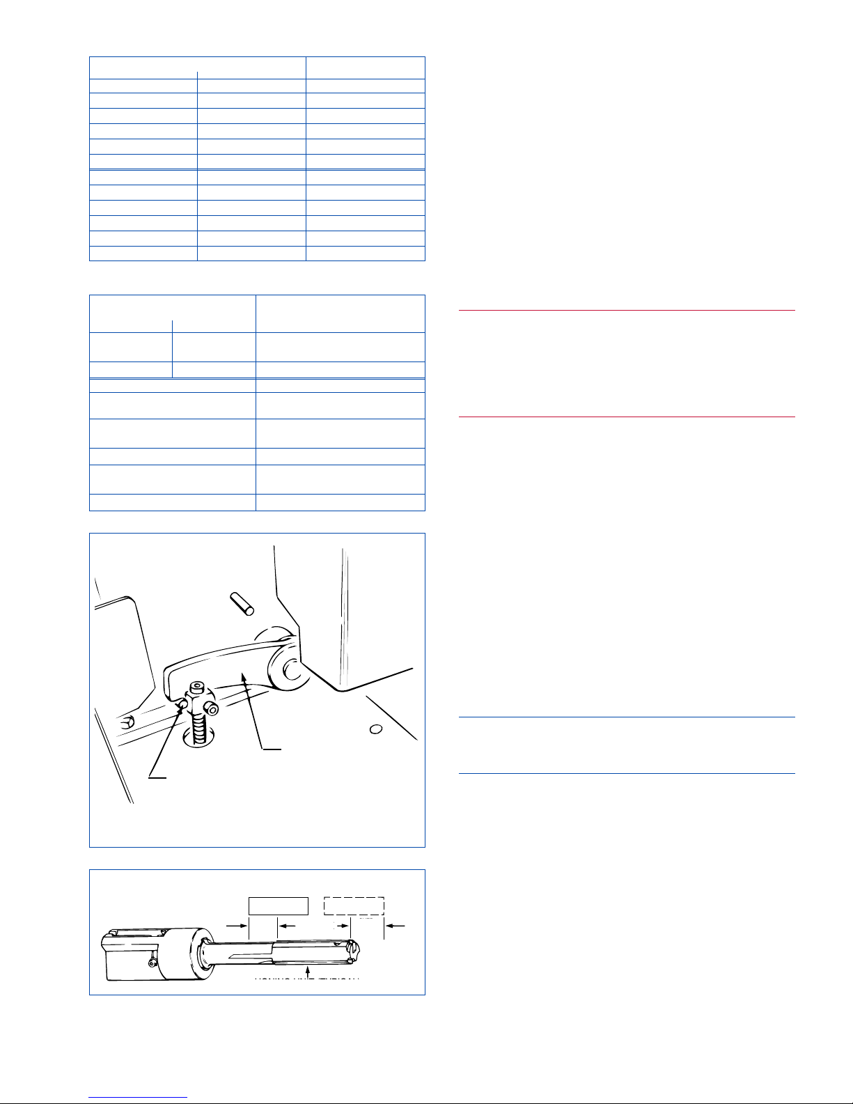
OIL ENTERS WORKPIECE
PARALLEL TO MANDREL
Page 23
Honing: Hone units for fitting king pins to spindles
are extra long in order to get perfect alignment
between bushings and to allow proper overstroking.
Adjust Work Support to absorb honing torque
(see
Figure 3-4)
. Set Heavy Cutting Pressure Dial to "0".
Set Light Cutting Pressure Dial between "2 to 3".
MANUAL HONING OPERATION
To manual hone bores, proceed as follow:
1. Follow Setup procedures (see Section 2).
Assemble and install Honing Unit in spindle.
Set cutting pressure and spindle speed.
Refer to
Tables 3-1 and 3-2
for pressure and speed settings.
4. With motor OFF, back off Feed Dial (counterclockwise) until workpiece slides on honing unit.
WARNING
To avoid serious injury to hands or fingers, never
try to absorb torque by holding workpiece in your
hand. Machine MUST always absorb honing
torque. Install workpiece in a Workholding
Fixture and use Work Support at all times.
5. Gage hole size, using Sunnen Hole Gage, to
determine amount of stock to be removed. Refer to
Operating Hints. for your particular application needs.
6. Install part in Workholding Fixture.
7. Depress Pedal and slide part on Mandrel, so part
is centered over stone.
8. While holding down on Pedal, turn Feed Dial
clockwise until Honing Dial readings is equal to
amount of stock to be removed, per step 4. Refer to
Stone Expansion Chart for various Mandrel types.
(
See Table 3-3, or Chart located on your Machine
above Heavy Cutting Pressure Dial.)
9. Turn workpiece several revolutions on Mandrel,
to seat workpiece on stone.
10. Release Pedal.
CAUTION
Machine MUST be set at proper Spindle Speed and
Pressure Control Setting.
11. Press START Button.
12. Adjust Coolant Nozzles. Direct coolant stream
onto both ends of honing unit so flow of coolant
will enter bore being honed
(see Figure 3-5).
Use a continuous and ample supply of Sunnen Industrial
Honing Oil to ensure accurate, fast honing and desired
finish. Do not dilute, cut, or change honing oil in any
way. Consistent results cannot be expected if anything
except the full strength recommended oil is used.
13. Slowly depress Pedal until Crank Arm hits Stop
Pin
(see Figure 3-6), meanwhile stroking fixture
forward and back on honing unit. If bore is rough or
out-of-round do not depress Pedal fully until bore
15
TABLE 3-3, Stone Expansion
STONE EXPANSION PER
HONING DIAL & FEED DIAL
millimeters inches HONING UNIT TYPE
0,025 .001
AN-600, AL-, ALH-, LH-, LJ-, ML-,
PL-, UL-, SL-0720 thru 1600
0,050 .002 CR-, HB-, KL-, RL-, RYY-, SC-
TYPE OF HONING UNIT TYPE OF WORK
RRY-, SL-, SYY-, LH-, LJ-, 3ML-, Pin fitting in psitons (both bushing
3PL- at the same end.
KL-, 1PL-, RL- Pin fitting in con rods and cylinder
reconditioning in small bore engines.
3ML-, 4ML-, 5ML-, 4PL-, 5PL-, UL- Kin pin fitting.
RL-, KL- Reconditioning hydraulic brake
cylinders.
CR- Con rod reconditioning.
NOTE: This information is also on machine stone feed chart on front of machine.
TABLE 3-2, Spindle Speed Selection
WORK DIAMETER SPINDLE
inches millimeters SPEED
UNDER 1.250 UNDER 32 640
1.250-1.625 32-41 500
1.625 - 2.000 41-51 400
2.000 - 2.500 51-64 320
2.500 - 3.250 64-83 250
OVER 3.250 OVER 18 200
UNDER .500 UNDER 13 640
.750 18 500
.875 22 400
1.000 25 320
1.500 38 250
OVER 2.000 OVER 51 200
CAUTION: Power MUST be OFF when Guard is open.
WORKPIECE
(at one end of stroke)
WORKPIECE
(at other end of stroke)
HONING UNIT (TYPICAL)
STROKE
OVER
STROKE
"A"
OVER
STROKE
"B"
FIGURE 3-7, Overstroke
FIGURE 3-6, Stop Pin
STOP PIN
CRANK
ARM
WORKPIECE
(AT ONE END OF STROKE)
WORKPIECE
(AT OTHER END OF STROKE)
STROKE
HONING UNIT (TYPICAL)
OVER
STROKE
(A)
OVER
STROKE
(B)
Page 24
has smoothed up, as evidenced by diminishing vibration.
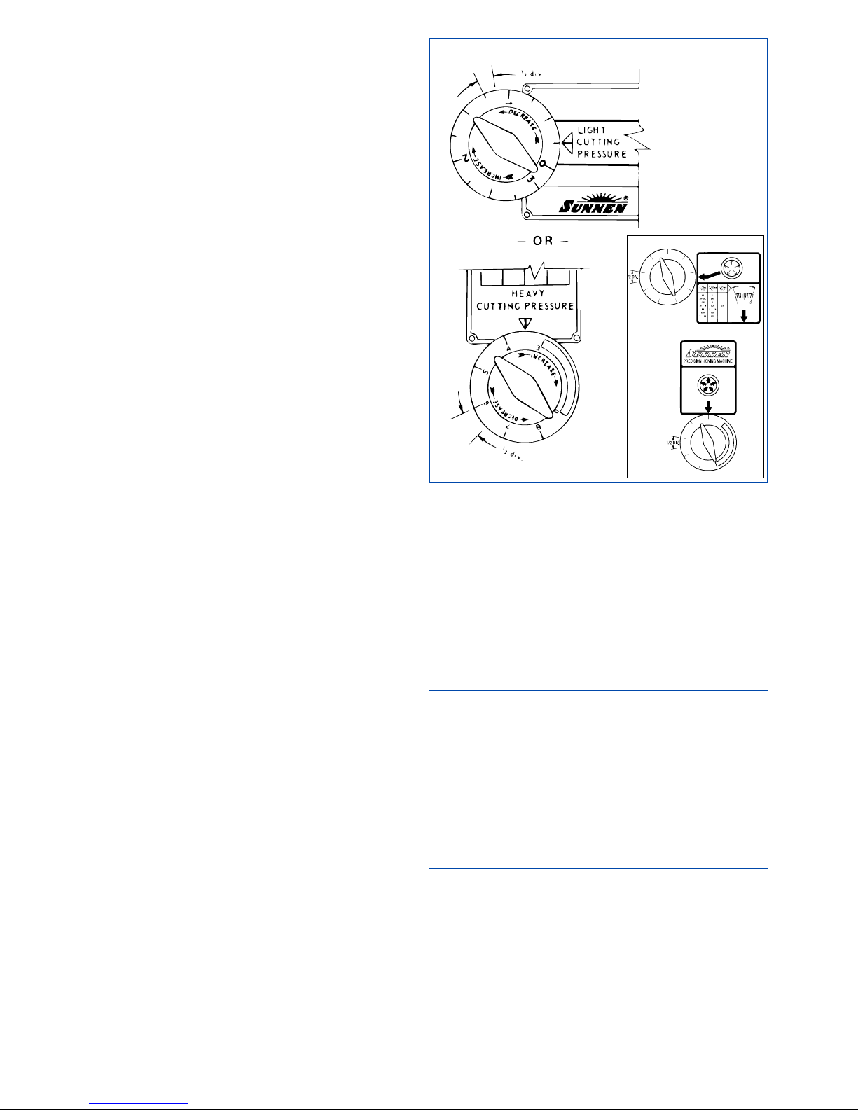
Overstroke each end of Stone by 1/4 to 1/2 bore length
or stone length, whichever is shorter
(see Figure 3-7).
Reverse the part on the honing unit frequently (be
sure spindle is stopped before putting workpiece on
or taking workpiece off the honing unit).
NOTE: If Honing Dial Needle moves too slowly,
increase Cutting Pressure. If Needle moves too
rapidly, decrease Cutting Pressure (refer to step 24).
19. When Honing Dial reads "0", release Pedal and
press Stop Button. Do not hone beyond (to right of) “0”:
You will lose your reference point and will not be
able to repeat size on succeeding parts.
Possible stone glazing and unpredictable finish.
Unnecessarily prolonged honing operation.
Loss of accuracy because of stone becoming loose
in bore.
20. Gage bore size.
21. Advance Feed Dial for amount of stock to be
removed, hone to “0” (zero), and gage.
22. Repeat as necessary until desired hole size is
reached.
23. Repeat honing operation for remaining parts.
When honing several parts, with each honing operation bore diameter will be undersize by amount of
stone wear. But by noting Honing Dial reading as
you start honing each part, you can tell whether
stock to be removed is uniform from part to part.
When parts have a uniform amount of stock to be
removed, you can accurately estimate how much
stone feed-up is needed before starting to hone.
Reset Feed Dial accordingly and hone until Honing
Dial reads "0". If you accurately estimated rate of
stone wear, when dial reads "0" part will be honed
to size. This allows part to be honed in one operation, without having to gage and hone each part several times until it is to size.
When parts vary widely in amount of stock to be
removed, you can NOT estimate how much stone
feed-up is needed. Generally it is better to hone part
until Honing Dial reads "0", gage hole, advance
Feed Dial accordingly to compensate for stone wear,
and then continue honing until hole size is reached.
24. The cutting pressure should be just enough to
produce good cutting action. Heavier pressure may
cause excessive stone wear; lighter pressure may
result in stone glazing instead of cutting. Increase or
decrease cutting pressure no more than 1/2 division
at a time
(see Figure 3-8) until most efficient
pressure is established. Changing cutting pressure
will cause a slight change in reading of Honing
Dial. Increasing pressure results in a smaller reading
and decreasing it could cause bore to go oversize.
For additional troubleshooting information,
see
Section 5. Troubleshooting
.
25. If the Honing Dial needle moves:
Too fast - stone is too soft or cutting pressure too
high or spindle speed is too slow.
Too slowly, or not at all - stone is too hard or is
glazed, or cutting pressure is not high enough, or
spindle speed is too high.
CAUTION
Do not increase cutting pressure for purpose of
breaking a glaze until you have tried dressing the
stone (see Sunnen Trouble-shooting Guide on next
page). Excessive pressure can cause unnecessary
stone wear, workpiece distortion and possibly cause
the bore to go oversize.
NOTE: Whenever Honing Dial needle reaches zero,
stop honing and gage.
26. As guide shoes wear, runout may again occur.
To correct this, loosen set screw No. 3 on the
spindle nose and tighten No. 1.
16
FIGURE 3-8, Cutting Pressure
Page 25
GENERAL
The following procedures and suggested maintenance
periods are given as guides only and are not to be
construed as absolute or invariable. Local conditions
must always be considered. Each machine must be
maintained individually according to its particular
requirements.
CLEANING
Daily: Wipe exterior of Machine with a clean dry
cloth.
Monthly: Wipe exterior of Machine with a clean dry
cloth; Wash exterior of Machine with warm water
and a mild detergent (or mild industrial solvent);
Rinse thoroughly with clean hot water; Wipe dry
with a clean dry cloth.
LUBRICATION
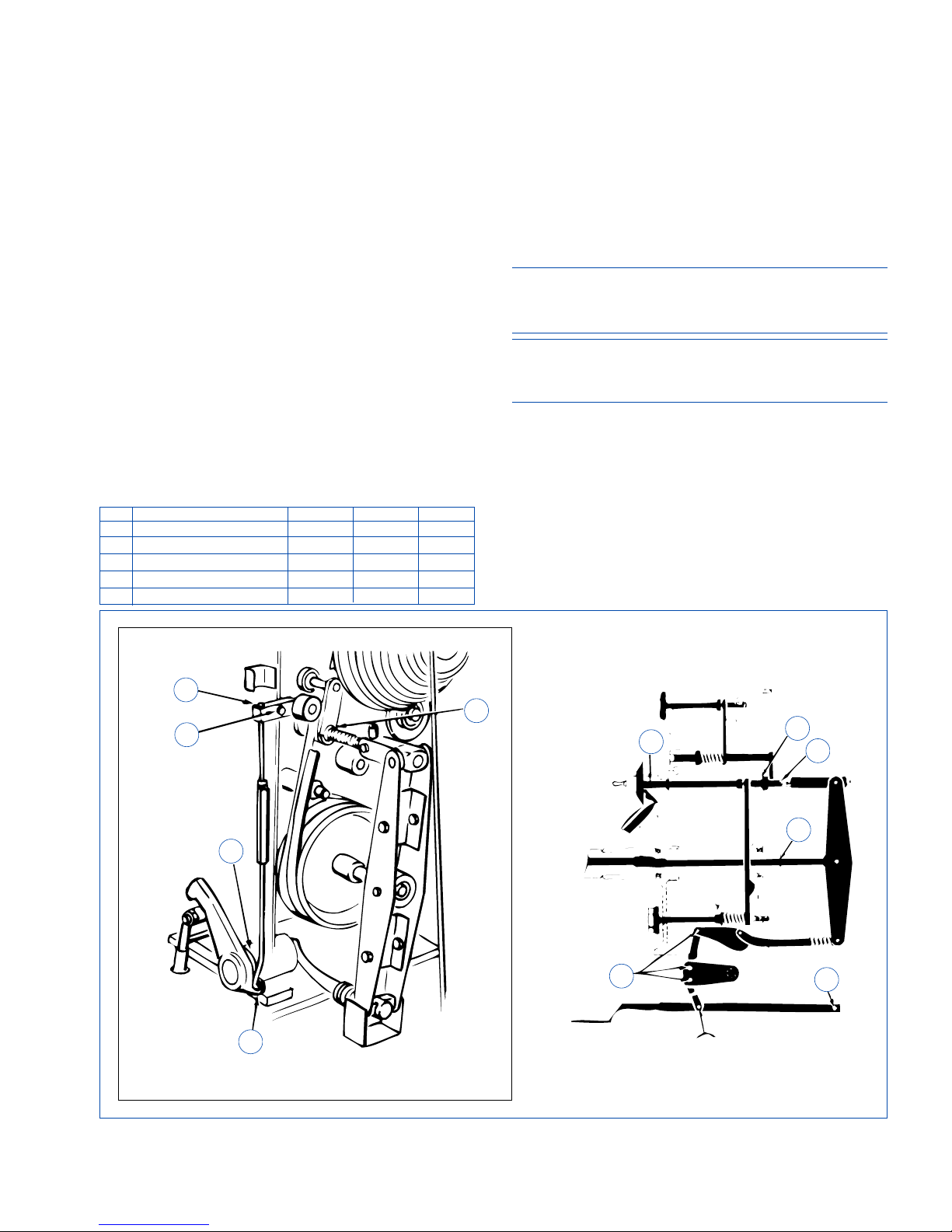
Hand lubricate various machine components called
out in Figure 4-1, according to suggested intervals
called out in
Table 4-1.
NOTE: The intervals between lubrication will vary
with amount of use your Machine receives. Lubricate
all components at least once every six months.
CAUTION
Be careful not to get oil on drive belts, pulleys, or
brake strap.
Oil or grease motor in accordance with manufacturer's
instructions. Avoid over-lubrication.
Spindle bearings are sealed and require no lubrication.
Coolant Pump requires no lubrication.
COOLANT LINES CHECK
Monthly inspect Coolant Lines and Fittings for
leaks, severe dents or kinks. Tighten any leaking
Fittings and replace damaged parts as required.
17
SECTION 4
ROUTINE MAINTENANCE
FIGURE 4-2, Lubrication
TABLE 4-1, Lubrication
ITEM DESCRIPTION LUBRICANT PROCEDURE INTERVALS
1 Brake Linkage (2) SAE #20 Oil Brush On Mthly
2 Feed Screw (3) SAE #20 Oil Brush On Mthly
3 Feed Rod (1) SAE #20 Oil Brush On Mthly
4 Light Press. Control Fork (1) SAE #20 Oil Brush On Mthly
5 Pedal Linkage (3) SAE #20 Oil Brush On Mthly
1
1
4
5
1
2
2
2
5
5
3
Page 26
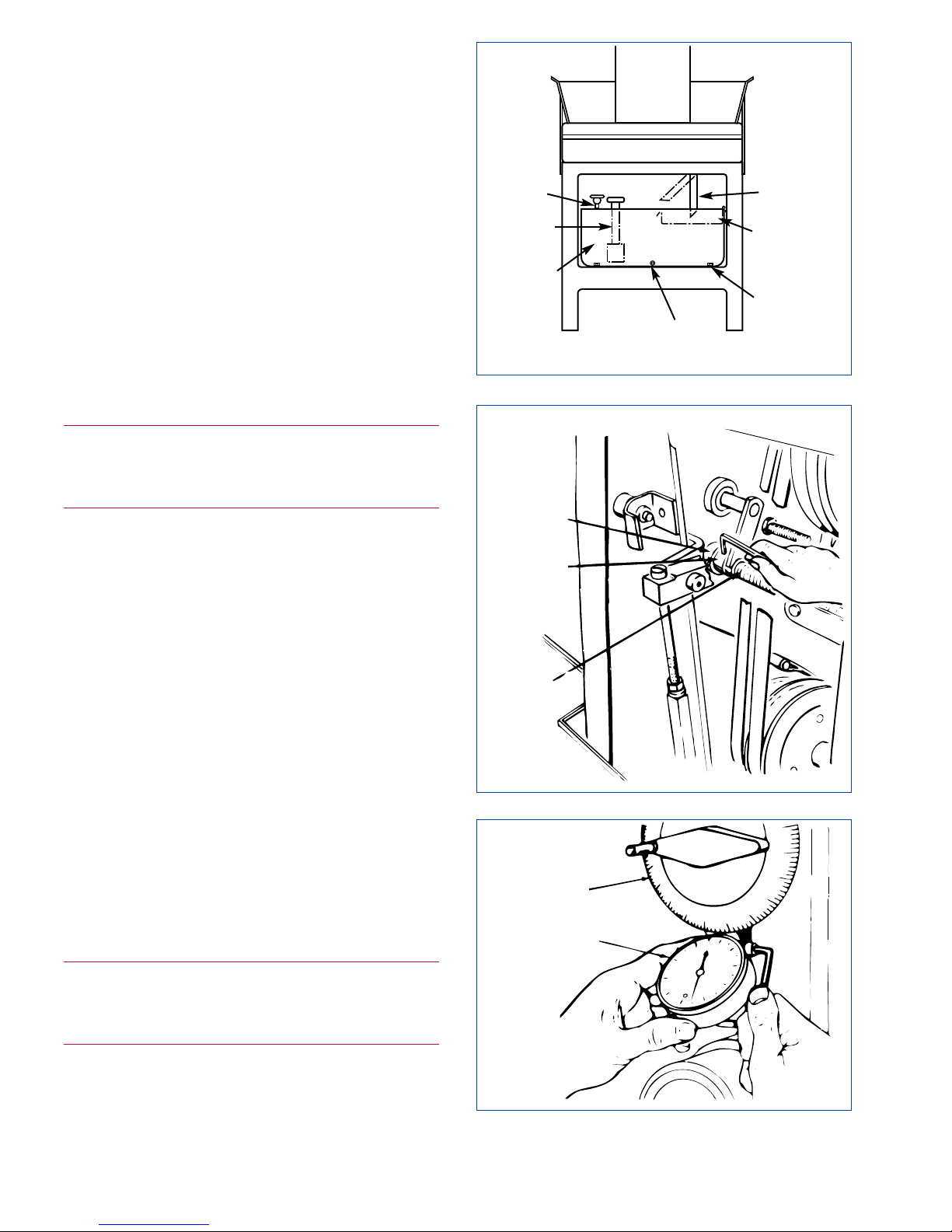
COOLANT LEVEL CHECK
Monthly check level of Coolant in Coolant
Reservoir and add Coolant as required by pouring
coolant into Work Tray
(refer to Appendix A).
Replace Coolant using ONLY Sunnen Industrial
Honing Oil or Sunnen Water-Based Coolant.
If the machine is low on coolant, order more
Sunnen Industrial Honing Oil. Do Not add
kerosene, cutting fluids, or any other fluids to
coolant that is left - it will ruin coolant. If you must
operate machine before you receive you new
coolant, temporarily drain and remove Sediment
Tray. If necessary, place a large chunk of metal in
reservoir to raise coolant level above pump inlet but remember this is a temporary expedient, and
remove chunk of metal when you refill reservoir.
Also, reinstall Sediment Tray.
SEDIMENT TRAY
Clean Sediment Tray as follows (see Figure 4-2):
WARNING
Turn electrical power OFF at main buss box or
main power source when performing any
maintenance not requiring power.
1. Turn OFF all electrical power to machine.
2. Open Access Door on front of machine.
3. Push Drain Pipe up to left.
4. Grasp Sediment Tray lip, which over-hangs right
side of Reservoir and tip tray to left, allowing coolant
to drain from sludge.
5. Remove Sediment Tray and dispose of sludge. If
not cleaning Reservoir, install Sediment Tray with
lip overhanging right side of Reservoir.
6. Pull Drain Pipe down and to right.
7. Close Doors on top and front of machine.
.8. Dispose of sludge according to local codes.
COOLANT RESERVOIR
Clean Coolant Reservoir as follows (see Figure 4-2):
1. Direct one or more Coolant Nozzles into a
separate container.
2. Press START Button, and pump coolant from
Reservoir.
WARNING
Turn electrical power OFF at main buss box or
main power source when performing any
maintenance not requiring power.
3. Press STOP Button, and turn off all power to
machine.
4. Open Access Door on front of machine.
18
FIGURE 4-3, Feed Dial
FIGURE 4-4, Honing Dial
BUSHING
FIGURE 4-2, Coolant Reservoir
CLAMP
KNOB
RESERVOIR
RETAINER
RESERVOIR
DRAIN
PLUG
SETTLEMENT
TRAY
PUMP
DRAIN PIPE
COLLAR
FEED
SCREW
FEED
DIAL
HONING
DIAL
Page 27

5. Push Drain Pipe up to left.
6. Tip Settlement Tray and allow oil to drain into
Reservoir.
7. Remove Settlement Tray and clean.
8. Uncouple flexible coolant line from coolant
manifold pipe near upper left corner of door opening by pulling and twisting on line.
CAUTION
Be careful not to get oil on drive belts, pulleys, or
brake strap.
9. Loosen Clamp Knob and remove belt from
Coolant Pump pulley.
10. Remove Coolant Reservoir by removing two (2)
1/4" Screws and Reservoir Retainers, then slide
Reservoir out of machine out 4-6 in. (100-150 mm).
11. Place a suitable container under Drain Plug.
12. Remove Plug and drain coolant from Reservoir.
NOTE: Drain hole may be clogged with sludge if
honing oil system has not been cleaned for a year or
more. Open hole with a 3/8 in. (10 mm) rod to unclog
it and drain the oil.
13. After coolant is drained, replace Drain Plug.
14. If necessary, remove Coolant Reservoir by
sliding Reservoir out of machine.
15. Dip or pour out any coolant remaining in
Reservoir.
16. Scrape or flush any remaining sludge from
Reservoir and Settlement Tray. If necessary, use a
mild industrial solvent.
17. Wipe reservoir and tray dry.
18. Pump screen is held in place by means of a thumb
screw underneath. Remove screen and clean.
20. Uncouple coolant line from pump and use air
pressure to blow out pump.
21. Reattach coolant line and reinstall screen.
22. Reinstall Coolant Reservoir in machine and
secure with two (2) Screws and Reservoir Retainers.
23. Pull Drain Pipe down and to right.
24. Reattach flexible coolant line to coolant
manifold pipe (refer to step 8).
25. Re-install belt and adjust for proper tension.
26. Pump Sunnen Honing Oil or Sunnen WaterBased Coolant into Coolant Reservoir or pour into
Work Tray.
27. Reinstall Settlement Tray.
28. Pull Drain Pipe down and to right.
29. Direct Coolant Nozzles into Work Tray and
close Total Volume Control Valve.
30. Close Door on front of machine.
31. Dispose of coolant and sludge according to local
codes.
CHECK FOR PROPER OPERATION
WARNING
Turn electrical power OFF at main buss box or
main power source when performing any
maintenance not requiring power.
FEED DIAL
To check Feed Dial end play, proceed as follows
(see Figure 4-3):
1. Set Light Cutting Pressure Control to zero.
2. Set Heavy Cutting Pressure Control to 4.
3. Push Feed Dial toward machine until you
encounter resistance. If Honing dial needle moves
more than one or two tenths during this check, there
is too much end play. To adjust go to step 4.
4. Open right-hand belt guard.
NOTE: Turn Disconnect Switch on left side of Belt
Guard to OFF position, then open doors.
5. Loosen set screw in Collar at rear of housing.
6. While lightly pushing in on Feed Dial, hold
Collar against rear of Bushing with light finger
pressure.
7. Rotate Collar slightly on shaft to give set a new
contact point and tighten set screw. Feed Screw
must rotate freely in Bushing.
If any binding occurs or if Bushing rotates with
Feed Screw, reset Collar.
HONING DIAL
To check for proper setup of Honing Dial, proceed
as follows
(see Figure 4-4):
1. Set the Light Cutting Pressure Control to 2.
2. Set Heavy Cutting Pressure Control to zero.
3. With zero on Honing Dial at the 6 o'clock position,
Honing Dial needle should be on red line.
If the honing dial needle is set to left of red line,
pressure on stone will decrease as you hone a part
close to zero, resulting in a drastic slowdown of cutting action. To adjust go to step 4.
With needle set on red line, you hone a part to zero
under full load. To adjust go to step 4.
It is all right if needle is set slightly to right of red line.
4. If zero on Honing Dial is not at 6 o'clock position,
loosen bezel clamp and turn to correct position.
19
Page 28
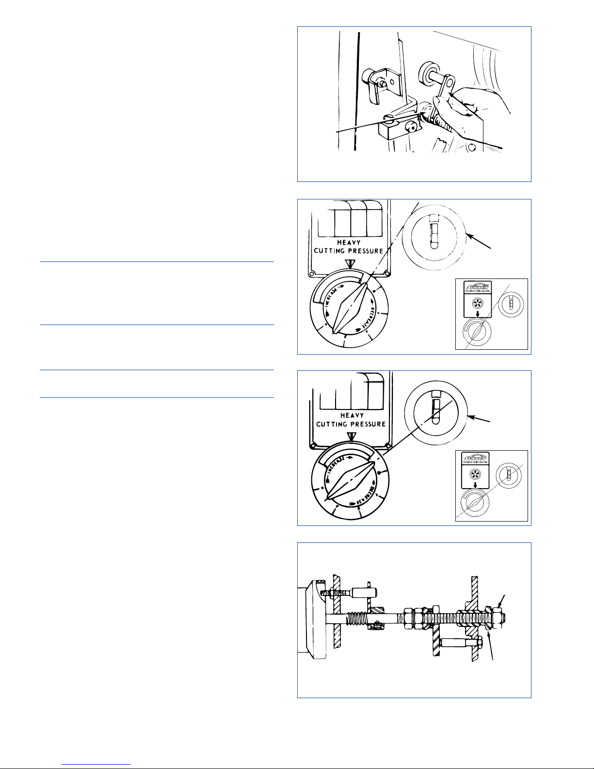
5. If needle is not on red line, loosen cap screw on
side of honing dial bracket and slide Honing Dial up
as far as it will go. Then move it down so that needle
makes one full turn. Continue moving indicator down
until needle is on red line. Tighten cap screw to hold
Honing Dial in this position.
6. Push Feed Dial in. Needle should return to red
line when Feed Dial is released.
7. If needle does not return to red line or if
sluggish: Remove Honing Dial from machine.
8. Make sure the honing dial plunger is clean and
works freely. Reinstall Honing Dial and adjust as
above.
9. If needle is still sluggish, clean and lubricate
body assembly.
CUTTING PRESSURE CONTROL
To check Cutting Pressure Control, proceed as follows:
CAUTION
Remove honing tool before checking or adjusting.
Also adjust the numbered set setscrews on the
spindle nose so that spindle nose is visually
concentric with spindle flange.
1. Hold Light Pressure Control Fork back so it does
not touch Collar during entire heavy pressure check
(see Figure 4-5).
NOTE: Turn Disconnect Switch on left side of Belt
Guard to OFF position, then open doors.
2. Rotate Feed Dial all of the way in either direction;
then back off six turns.
3. Set Heavy Cutting Pressure Control to zero.
4. Set Light Cutting Pressure Control to zero.
5. Push Feed Dial in and release very slowly. Honing
dial needle should read at some point greater than 5
on dial.
6. Rotate Heavy Cutting Pressure Control so handle
is in line with upper surface of Spindle Nose
(see
Figure 4-6)
. Honing dial needle should move to
between 4 and 5.
7. Continue rotating Heavy Cutting Pressure Control
until handle is in line with spindle centerline
(see
Figure 4-7)
. Honing dial needle should move past
zero to the red line.
If everything is okay, skip to
step 25.
To adjust, proceed with
step 8.
8. Turn machine OFF.
9. Make sure Feed Dial is not at either extreme end
of travel.
10. Loosen Locknut (A) on Light Cutting Pressure
Control shaft
(see Figure 4-8).
20
FIGURE 4-5, Light Pressure Control Fork
FIGURE 4-6, Heavy Cutting Pressure Control
FIGURE 4-7, Heavy Cutting Pressure Control
FIGURE 4-8, Light Cutting Pressure Control
SPINDLE
NOSE
LOCKNUT
(A)
COLLAR
LIGHT CUTTING
PRESSURE
CONTROL FORK
SPINDLE
NOSE
THREADED
SLEEVE (B)
Page 29
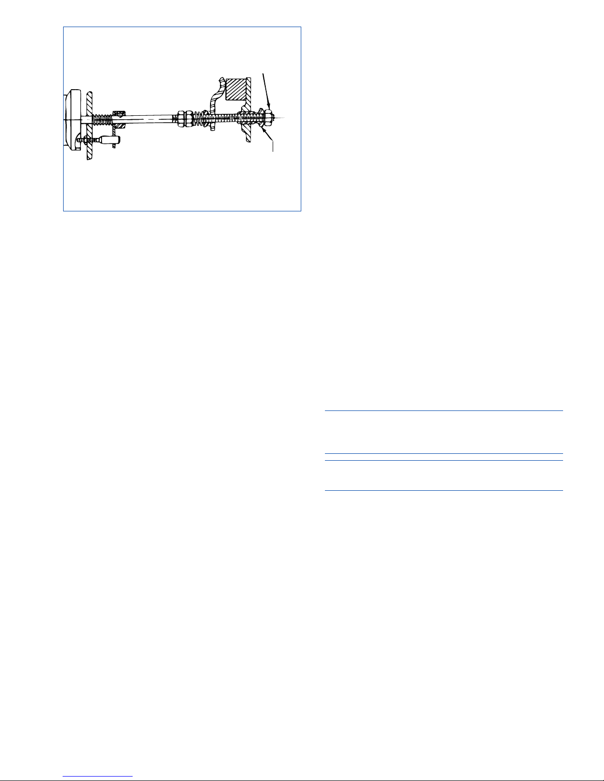
11. Rotate Light Cutting Pressure Control all the
way counterclockwise against stop (to zero).
12. Turn Threaded Sleeve (B) clockwise (as viewed
from rear of machine) until light pressure control
fork will not return to contact collar when it is
pulled away (refer to Figure 4-5).
13. Loosen Locknut (C) on Heavy Cutting Pressure
Control shaft
(see Figure 4-9).
14. Rotate Heavy Cutting Pressure Control all the
way counterclockwise against stop (to zero).
15. Turn Threaded Sleeve (D) clockwise (as viewed
from rear of machine) until honing dial needle will
not return to zero when Feed Dial is pushed all the
way in and slowly released.
16. Set Heavy Cutting Pressure Control so that
handle is in line with upper surface of spindle nose
(refer to Figure 4-6).
17. Push Feed Dial in as far as you can and release
slowly.
18. While holding Heavy Cutting Pressure Control
in position set in step 21, watch Honing Dial and
turn threaded sleeve D counterclockwise slowly
until honing dial needle moves to between 4 and 5.
If honing dial needle suddenly moves to red line, stop
adjusting threaded sleeve D. Push in on Feed Dial
again and release slowly. If needle stops between
4 and 5, adjustment of threaded sleeve D is correct.
If needle still moves quickly to red line, turn threaded
sleeve D clockwise a small amount and again push
Feed Dial in and release slowly.
Continue adjusting threaded sleeve D until needle
stops between 4 and 5 when Feed Dial is pushed are
released slowly.
19. Tighten locknut C against threaded sleeve D.
20. Recheck threaded sleeve D adjustment by pushing
Feed Dial in as far you can and releasing slowly . . .
honing dial needle should stop between 4 and 5. If
it doesn't, loosen locknut C and repeat step 18.
21. Make sure both pressure controls are turned all
the way counterclockwise against stops (to zero).
22. Push Feed Dial in as far as you can and release
slowly.
23. While holding light cutting pressure control
against stop (at zero) watch honing dial and turn
Threaded Sleeve B slowly counterclockwise until
the needle moves to between 8 and +1
(refer to
Figure 4-8)
.
If needle suddenly moves past 8 toward red line,
stop adjusting Threaded Sleeve B. Push in on Feed
Dial again and release slowly.
If honing dial needle stops between 8 and +1,
adjustment of Threaded Sleeve B is correct. If honing
dial needle still moves quickly past 8 toward red area,
turn Threaded Sleeve B clockwise, a. small amount
and again push Feed, Dial in and release slowly.
Continue adjusting Threaded Sleeve B until needle
stops between 8 and +11 when Feed Dial is pushed
in and released slowly.
24. Tighten Locknut A against Sleeve B. Approximate
adjustment of Light Pressure Control is now complete.
8. Set Heavy Cutting Pressure Control to zero.
9. Set Light Cutting Pressure Control to zero.
10. Check light pressure control fork to make sure it
is seated on shoulder of collar
(refer to Figure 4-5).
IMPORTANT
Turn machine ON but do not run spindle while Steps
11 and 12 are performed.
CAUTION
Belt guard must be closed when motor is on.
11. Push Feed Dial in. Slowly release. Honing dial
needle should move toward red line and stop
between 0 and 2, or just barely continue to move.
12. Rotate Light Cutting Pressure Control to 1/2.
Honing dial needle should move to red line.
If everything is okay, continue with step 8.
If not, skip to step 13.
25. Recheck Light Cutting Pressure Control (Sleeve
B) as instructed in steps 8-12.
If the honing dial needle moves quickly to the red
line in Step b.(5). push the Stop button and allow
motor to stop. Open belt guard. Loosen Locknut A
and turn Sleeve B clock-wise a small amount.
Tighten Locknut A against Sleeve B.
Recheck Sleeve B adjustment as necessary using the
procedure in Step (18) above.
21
FIGURE 4-9, Heavy Cutting Pressure Control
LOCKNUT
(C)
THREADED
SLEEVE (D)
Page 30
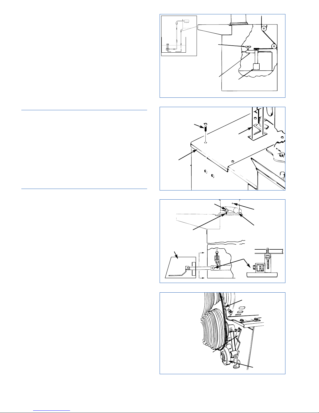
COOLANT SYSTEM
Oil Flow
TO CHECK the oil flow, point oil jets to direct flow
into Work Tray. Turn machine ON. Open Total
Volume Control Valve slightly. Adjust Individual
Oil jet Control Valves for desired volume of oil,
opening Total Volume Valve further as needed. Total
Volume Valve may then be used to shut entire
supply off, leaving individual settings unchanged.
TO ADJUST the oil flow, check first to be sure oil
level covers the pump housing. Make sure the oil
pump belt is taut and in good condition. Also check
screen on oil pump to make sure it is not clogged
(see Figure 4-10).
NOTE: If the machine is low on oil, order more
Sunnen Industrial Honing Oil. DO NOT ADD
KEROSENE, CUTTING FLUIDS, OR ANY
OTHER FLUID TO THE OIL THAT'S LEFT - IT
WILL BE RUINED. If you must operate the machine
before you receive your new oil, temporarily drain
and remove Sediment Tray. Place a large chunk of
metal in the reservoir if necessary to raise the oil
level above the pump inlet - but remember this is a
temporary expedient, and remove the chunk of metal
when you refill the reservoir. Also, reinstall the
Sediment Tray.
Oil Pump Belt
TO CHECK the oil pump belt, it should be just tight
enough to turn the oil pump pulley without slipping.
If oil pressure falls excessively when spindle
rotates, oil pump belt may be too loose.
TO ADJUST the oil pump belt, make sure reservoir
is pushed back into the machine as far as it will go.
If belt needs adjusting, loosen Clamp Knob in top
of Pump Bracket and move Bracket as needed.
Retighten Clamp Knob.
Installing New Oil Pump Belt (Part No. MB-2292)
Remove left rear cover
(see Figures 4-10 and 4-11).
Loosen Clamp Knob in top of Pump Bracket.
Remove oil pump belt. Thread new oil pump belt
around drive pulley, idler pulleys, and pump pulley.
Adjust tension and tighten clamp knob.
PEDAL ADJUSTMENT
The Pedal can be adjusted in or out; up or down;
and for standing or sitting. Pedal when fully
depressed MUST be at least 6 mm (.25 in.) from
floor and not higher than 50 mm (2 in.) from floor.
To check: Crank Arm must hit Lower Stop Pin when
Pedal is between 6-13 mm (.25-.50 in.) from floor.
When Pedal is released, Crank Arm should hit Upper
Stop Pin.
To adjust, proceed as follows
(see Figure 4-12):
22
FIGURE 4-13, Motor V-Belt
V-BELT
TENSION
RELEASE
LEVER
IDLER
FIGURE 4-10, Pump
FIGURE 4-11, Belt
FIGURE 4-12, Pedal
CLAMP
KNOB
PUMP
BRACKET
PUMP
SCREEN
BELT
LEFT
REAR
COVER
SCREW
UPPER
STOP PIN
CRANK
ARM
ADJUSTING
SCREW
LOWER
STOP PIN
PEDAL
CLAMP
SCREW
PEDAL
COVER
SEE APPENDIX D
Page 31
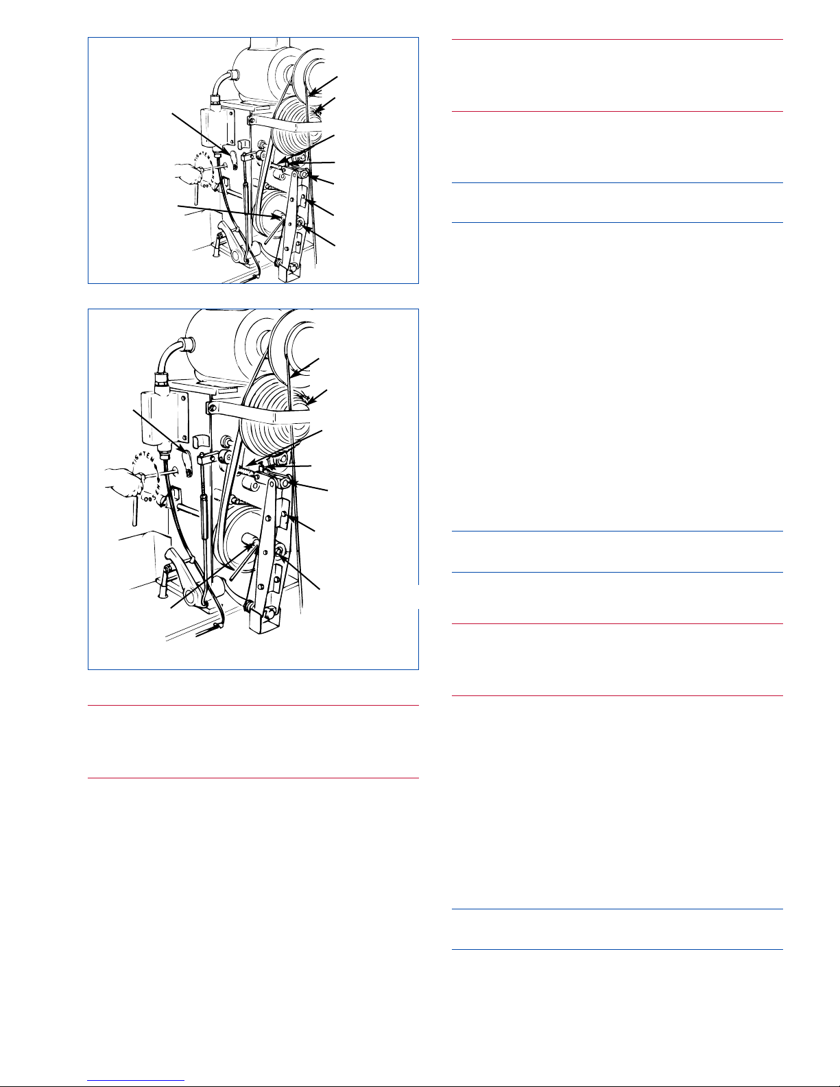
23
WARNING
Turn electrical power OFF at main buss box or
main power source when performing any
maintenance not requiring power.
1. Turn OFF all electrical power to machine.
2. Pedal, when fully depressed, MUST be at least
6 mm (.25 in.) from floor and not higher than 50 mm
(2 in.) from floor. Adjust Pedal height by turning
Self Locking Nuts on end of Pedal Link Assembly.
Assembly should be adjusted evenly on both sides.
3. The Pedal Assembly may be adjusted in or out
by loosening pedal clamp screw, sliding Pedal
Assembly in or out, and tightening pedal clamp
REPLACE MOTOR V-BELT
To inspect and replace Motor V-Belt, proceed as follows
(see Figure 4-13).
WARNING
Turn electrical power OFF at main buss box or
main power source when performing any
maintenance not requiring power.
1. Turn OFF all electrical power to machine.
2. Loosen safety latch pin, raise belt cover latch
and open belt guard.
NOTE: Turn Disconnect Switch on left side of Belt
Guard to OFF position, then open doors.
3. Inspect Motor V-Belts for signs of wear and/or
damage. Replace as required, proceed with step 4.
4. Pull Tension Release Lever down.
5. Remove Motor V-Belts.
6. Install New Motor V-Belt. Align on upper and
lower pulleys.
7. Pull out and up on Tension Release Lever.
8. Close and secure belt guard.
9. Turn ON power.
ADJUST SPINDLE DRIVE BELT
To check flat spindle drive belt adjustment, tension
should be such that with motor ON, spindle starts
rotating an instant after the brake releases, as the
Pedal is slowly depressed.
NOTE: If Motor V-belt is excessively worn, replace
it before attempting to adjust the flat drive belt.
To inspect and adjust the flat spindle drive belt
tension, proceed as follows
(see Figure 4-14):
WARNING
Turn electrical power OFF at main buss box or
main power source when performing any
maintenance not requiring power.
1. Turn OFF all electrical power to machine.
2. Loosen safety latch pin, raise belt cover latch
and open belt guard to expose the belt adjusting
screw.
4. Pull out and up on Tension Release Lever. Lever
must be in up position to properly adjust belt.
5. Turn the adjusting screw clockwise to loosen
belt, counterclockwise to tighten.
Idler should travel 11/16 to 3/4 in. (17-19 mm) as
Pedal is depressed.
NOTE: Adjusting belt may cause the brake to
require adjusting.Refer to Brake Operation.
6. Close and secure belt guard.
7. Turn ON power.
FIGURE 4-14, Spindle Drive Belt
LOWER CONE
PULLEY
COVER
PLATE
PUMP BELT
FEED SCREW
PROJECTION
ADJUSTING
NUT ASSY
FEED ARM
ASSY
CROSS HOLE
IN FEED ROD
THRUST
ASSY &
SCREW
FIGURE 4-15, Spindle Drive Belt
LOWER CONE
PULLEY
COVER
PLATE
PUMP BELT
FEED SCREW
PROJECTION
ADJUSTING
NUT ASSY
FEED ARM
ASSY
CROSS HOLE
IN FEED ROD
THRUST ASSY &
SCREW
Page 32

REPLACE SPINDLE DRIVE BELT
To inspect and replace Flat Spindle Drive Belt,
proceed as follows
(see Figure 4-15):
WARNING
Turn electrical power OFF at main buss box or
main power source when performing any
maintenance not requiring power.
1. Turn OFF all electrical power to machine.
2. Loosen safety latch pin, raise belt cover latch
and open belt guard.
NOTE: Turn Disconnect Switch on left side of Belt
Guard to OFF position, then open doors.
3. Inspect Spindle V-Belts for signs of wear or
damage. Replace as required, proceed with step 4.
4. Remove Oil Pump Belt from motor pulley and
carefully drape it over side of machine so it doesn't
get oil on it or come off the idlers or the oil pump
pulley (Installing New Oil Pump Belt).
5. Pull tension release lever
(see Figure 4-16)
down.
5. Remove Motor V-Belt. Slip Motor V-Belt off
Lower Cone Pulley.
6. Remove two Bolts and Nuts securing Feed Arms
as follows:
Insert 3/16 in. (5 mm) rod in Cross Hole in Feed Rod
to keep Feed Rod from turning
(refer to Figure 4-16).
Using 5/16 in. hex wrench, remove Screw and
washer from Thrust Assembly.
7. Turn Feed Dial counterclockwise all the way
until Adjusting Nut Assembly is clear of Feed
Screw.
8. Separate Arms and remove. Pull Feed Arm
Assembly with Thrust Assembly off Feed Rod.
9. Push tension release lever up and remove old flat
drive belt.
10. Remove old Flat Spindle Drive Belt and install
new Belt.
11. Ensure projection on Adjusting Nut Assembly is
pointed upward; then, install Feed Arms and secure
with Nuts and Bolts removed in step 6.
Reassemble Feed Arm Assembly to Feed Rod by
engaging Adjusting Nut Assembly with Feed Screw
and turning Feed Dial clockwise while inserting
Feed Rod into Thrust Assembly. Projection on
Adjusting Nut Assembly must point upward.
Bearing retaining screws in Thrust Assembly must
face back of machine head.
12. Pull tension release lever down.
13. Install Motor V-Belt. Align on Lower Cone
Pulley and motor pulley.
14. Pull out and up on Idler Handle.
15. Replace Oil Pump Belt.
16. Close and secure belt guard.
17. Turn ON power.
ADJUST BRAKE STRAP
To check brake operation, observe spindle when
pedal is released, the honing machine spindle
should stop instantly.
Adjusting Brake Strap Tension will increase or
decrease time required for spindle to come to a
complete stop after honing operation is completed.
Adjust tension as follows
(see Figure 4-17):
WARNING
Turn electrical power OFF at main buss box or
main power source when performing any
maintenance not requiring power.
1. TURN OFF all electrical power to machine.
2. Loosen safety latch pin, raise belt cover latch
and open belt guard.
NOTE: Turn Disconnect Switch on left side of Belt
Guard to OFF position, then open doors.
3. Loosen Socket Head Capscrew (E) in Brake
Cam, using 1/4" hex wrench (see Figure 4-19).
4. Rotate Brake Cam until Brake Strap is loose.
5. Loosen 7/16" Locknut (A) on Brake Adjusting
Screw.
6. While holding Brake Cam up as far as possible,
adjust Brake Adjusting Screw (D) until screw head
just contacts Ridge on Brake Lever. Then tighten
Locknut.
7. Rotate Brake Cam counterclockwise to take up
slack in Brake Strap; and Brake Lever is horizontal
(refer to Figure 4-19). Then tighten Capscrew (E).
8. Close right side of Belt Guard and reinstall
Button Head Capscrew removed in step 4.
24
FIGURE 4-16, Tension Release Lever
TENSION
RELEASE
LEVER
Page 33
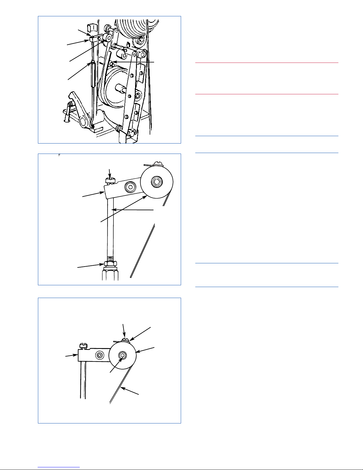
9. Recheck Brake Strap Tension Adjustment after
10 hours of operation and readjust as required.
REPLACE BRAKE STRAP
To replacement worn or broken Brake Strap proceed
as follows
(refer to Figures 4-18 & 19):
WARNING
Turn electrical power OFF at main buss box or
main power source when performing any
maintenance not requiring power.
1. Turn OFF all electrical power to machine.
2. Push E-STOP Button.
3. Loosen safety latch pin, raise belt cover latch
and open belt guard.
NOTE: Turn Disconnect Switch on left side of Belt
Guard to OFF position, then open doors.
4. Release Brake by raising Brake release Lever.
5. Step on Pedal and remove Brake Strap from
Brake Anchor stud
(refer to Figure 4-17). Then
release pedal.
6. Loosen Locknut (A).
7. Loosen Socket Head Capscrew (D) in Brake
Cam, using 1/4" hex wrench.
8. Remove Slotted Head Screw (C) and Washer
from Brake Cam. Discard worn Brake Strap
(refer
to Figure 4-18)
.
9. Clean groove in which strap rides on Spindle
Pulley.
CAUTION
Brake Strap must, be positioned on Brake Cam and
spindle pulley as shown.
10. Install new Brake Strap on Brake Cam, using
Screw and Washer removed in step 6.
11. Wrap Brake Strap around groove in Spindle
Pulley and install on Brake Anchor. Position strap
loop on Brake Anchor Stud so Strap is aligned with
the brake strap groove in the spindle pulley.
12. Adjust Brake Strap Tension as required (see
Adjust Brake Strap Tension).
13. Close right side of Belt Guard and reinstall
Button Head Capscrew removed in step 4.
14. Recheck Brake Strap Tension Adjustment after
10 hours of operation and readjust as required.
25
FIGURE 4-17, Brake
FIGURE 4-18, Brake
SCREW
(D)
BRAKE
LEVER
BRAKE
CAM
LOCKNUT
(A)
BRAKE
ANCHOR
STUD
BRAKE
ANCHOR
STUD
LOCKNUT
(A)
SCREW
(D)
BRAKE
LEVER
BRAKE
CAM
FIGURE 4-19, Brake
BRAKE
CAM
BRAKE
STRAP
SCREW
BRAKE
LEVER
SCREW
(E)
WASHER
Page 34

NOTES
26
Page 35

27
GENERAL
This section contains Troubleshooting information
in table form which should be used when problems
occur with machine. The table lists problems
encountered, possible causes, and solutions for
problems along with reference to section of manual
where detailed instructions may be found to correct
problems.
OPERATIONAL TROUBLESHOOTING
For suggestions on correcting problems with bore
conditions or with honing operation; consult
Table 5-1.
WARNING
An arc flash hazard exists. follow safe work practices
and wear appropriate personal protective equipment.
Follow proper lockout / tagout procedures.
Failure to
comply can result in death or injury.
SECTION 5
TROUBLESHOOTING
PROBLEM PROBABLE CAUSE SOLUTIONS SEC.
Stone not cutting 1. Stone Glazing A. Dress stone
(Honing Dial B. Increase cutting pressure
Needle moves C. Increase stroking speed
too slowly D. Use softer stone
E. Check coolant* 4
2. Stone Loading A. Dress stone
B. Increase stroking speed
C. Use softer stone
D. Use coarser stone
E. Check coolant* 4
Slow stock 1. Improper spindle speed A. Increase spindle speed
removal (Honing 2. Inadequate stone feed up A. Increase cutting pressure
Dial Needle 3. Improper stone A. Use softer stone
moves too slowly) B. Use coarser stone
4. Improper or diluted coolant* A. Check coolant* 4
Poor stone life 1. Excessive stone feed up A. Decrease cutting pressure 2
(Honing Dial 2. Inadequate spindle speed A. Increase spindle speed 2
Needle moves) 3. Improper stone A. Use harder stone
too fast) B. Use coarser stone
4. Improper or dilute coolant* A. Check coolant* 4
Bellmouth (Bore 1. Mandrel not trued A. True stone & shoes
longer than 2/3 2. Short or unbalanced part A. Shorten stroke length 2
stone length) 3. Improper stone A. Use softer stone
4. Improper stone length A. Shorten stone only slightly on
each end
Bellmouth (Bore 1. Mandrel not trued A. True stone & shoes
shorter than 2/3 2. Short or unbalanced part A. Shorten stroke length 2
stone length) 3. Improper stone A. Use softer stone
4. Improper stone length A. Shorten stone & shoes equally to
1-1/2 times bore length
*NOTE: Many honing problems, such as poor stone life, and rough finish, are caused by wrong coolant; insufficient
coolant, dirty coolant, or contaminated coolant. Use ONLY clean, Sunnen Industrial Honing Oils or Water-Based Coolant.
Make sure that coolant is neither diluted nor "cut" with other coolants. Keep solvents and cleaning fluids away from
Machine.
TABLE 5-1, Operational Troubleshooting Index
Page 36

28
PROBLEM PROBABLE CAUSE SOLUTIONS SEC.
Barrel 1. Mandrel not trued A. True stone & shoes
2. Improper stone length A. Use longer stone or shorten guide
shoes on both ends
B. Use mandrel with longer stone &
shoes
3. Improper stone A. Use finer stone
Taper in Open Hole 1. Workpiece is not being reversed A. Reverse workpiece on mandrel
2. Mandrel not trued A. True stone & shoes
3. Improper stroke A. Lengthen overstroke on tight end
4.
Stroker Arm and Spindle not aligned
A. Align Stroker Arm and Spindle
Taper in Blind Hole 1. Improper stone length A. Shorten stone and shoes to 3/4
length of bore
B. True stone & shoes frequently
2. Inadequate oil flow A. Adjust Oil Nozzle
3. Inadequate relief in blind end A. Provide sufficient relief
B. Short stroke tight end
C. Use hard tip stone
Out-Of-Round 1. Undersize honing tool A. Change honing tool 2
2. Mandrel not true A. True stone & shoes
3. Workpiece flexing (thinwall) A. Decrease cutting pressure 2
4. Improper stone A. Use softer stone
Waviness 1. Improper mandrel or stone length A. Use mandrel with sufficient stone
length to bridge waviness in bore
Rainbow 1. Improper mandrel A. Use L, BL or multi-stone mandrel
(stone length should be 1-1/2
times bore length
2. Improper stroke A. Shorten overstroke
3. Improper stone A. Use softer stone
Rough Finish 1. Improper feed A. Decrease cutting pressure 2
2. Mandrel not trued A.
True stone & shoes to exact hole dia.
3. Improper stone A. Use finer stone
4. Improper or diluted coolant* A. Check coolant* 4
5. Soft or exotic materials A. Use bronze mandrel or bronze
shoes
Scratches in Bore 1. Improper feed A. Decrease cutting pressure 2
(Random) 2. Improper stone A. Use finer stone
B. Use softer stone
3. Improper mandrel A.
If using hard steel mandrel, change to
soft steel mandrel; If using soft steel
mandrel, change to bronze mandrel
4. Improper or diluted coolant* A. Check coolant* 4
*NOTE: Many honing problems, such as poor stone life, and rough finish, are caused by wrong coolant; insufficient
coolant, dirty coolant, or contaminated coolant. Use ONLY clean, Sunnen Industrial Honing Oils or Water-Based Coolant.
Make sure that coolant is neither diluted nor "cut" with other coolants. Keep solvents and cleaning fluids away from
Machine.
Page 37

29
SETUP - GENERAL (Section 2)
o 1. Press STOP Switch.
o 2. Turn OFF oil supply.
o 3. Select Stone.
o 4. Select Honing Unit.
o 5. Assemble Honing Unit.
o 6. Adjust Feed Dial.
o 7. Install Honing Unit.
o 8. Set Spindle Speed to 200 rpm.
o 9. Adjust Cutting Pressure.
o 10. Press START Button.
o 11. Adjust Light Cutting Pressure.
o 12. Reduce Mandrel Runout.
o 13. Set Spindle rpm to desired operating speed.
o 14. Adjust Stroke Stops (if used).
o 15. Adjust Cutting Pressure.
o 16. Adjust oil supply.
o 17. True Mandrel and Stone.
o 18. Adjust Work Support Arm.
OPERATION - MANUAL STROKE HONING (Section 3)
o 19. Press STOP Button.
o 20. Back off Feed Dial.
o 21. Gage bore size.
WARNING: To avoid serious injury to hands or fingers, never try to absorb torque by holding workpiece
in your hand. Machine MUST always absorb honing torque. Install workpiece in a Workholding Fixture
and use Work Support at all times.
o 22. Install part in workholding fixture.
o 23. Slide part and fixture on mandrel.
o 24. Depress Pedal.
o 25. Adjust Feed Dial for stock to be removed.
o 26. Release Pedal.
o 27. Press START Button.
o 28. Adjust Oil Nozzles.
o 29. Depress Pedal and hone until Honing Dial reads "0".
o 30. Release Pedal and remove part.
o 31. Gage bore size.
o 32. Continue to hone until desired bore size is reached.
o 33. Repeat honing operation for remaining parts.
APPENDIX A
CHECKLIST
SETUP & OPERATION SEQUENCE
WARNING
Use caution when opening belt guards once
power is shut off; pulleys may still be turning as
motor coast to a stop.
WARNING
An Arc Flash Hazard Exists. Follow safe
work practices and wear appropriate
Personal Protective Equipment. Follow
proper lockout/tagout procedures. Failure
to comply can result in death or injury.
WARNING
Do not wear cotton or heavy gloves while
operating this equipment! If gloves must be
worn, wear only the tear-away type.
Page 38

NOTES
30
Page 39
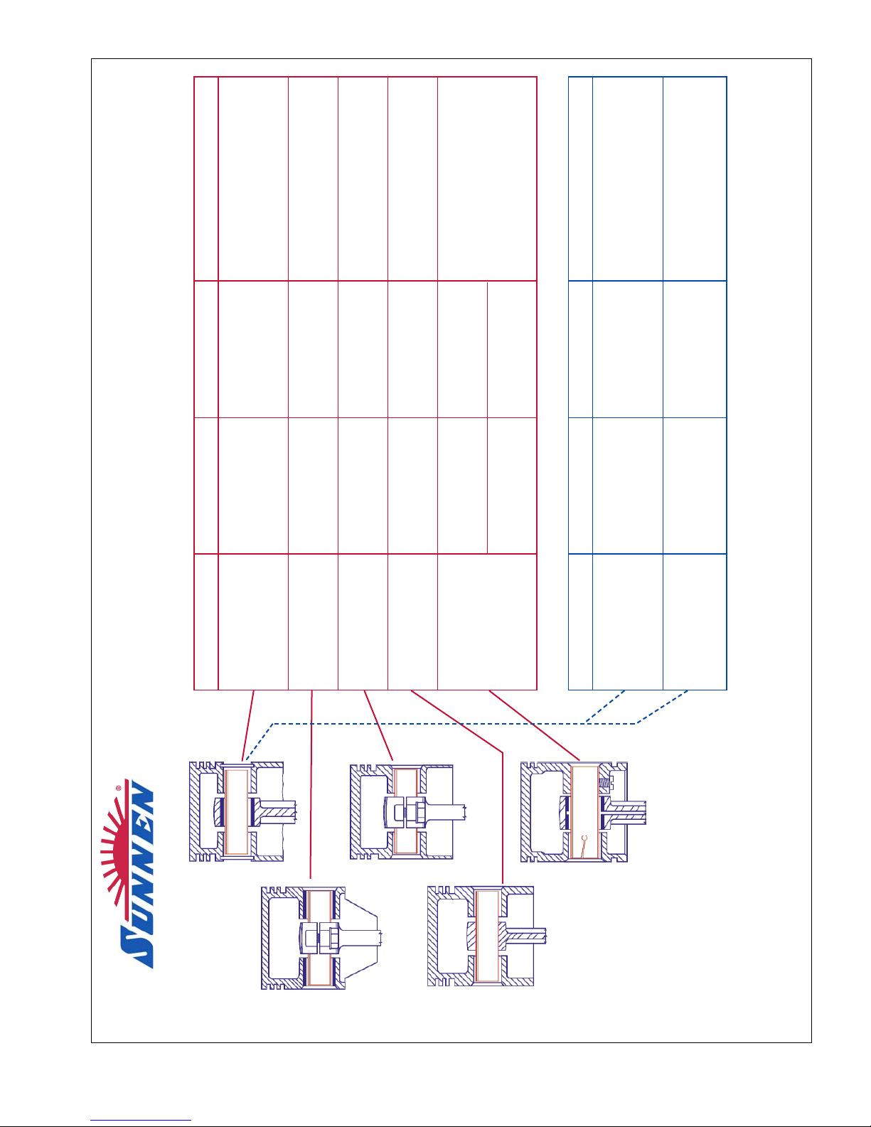
APPENDIX B
RECOMMENDED PIN CLEARANCES
PRECISION PIN FITS ON ENGINES WITH 19 to 32 mm DIAMETER PINS
DIAMETER ALUMINUM PISTON CAST IRON PISTON CONNECTING RODS
0,008 to 0,013 clearance
FULL 0,003 to 0,008 0,008 to 0,013
(all pressure feed, 0,0127 to
FLOATING clearance clearance
0,0178 clearance)
OSCILLATING 0,008 to 0,013
in bushed piston clearance
Clamped in Rod
OSCILLATING 0,008 to 0,013 0,015 to 0,020
in piston (no bushing) clearance clearance
Clamped in Rod
OSCILLATING 0,008 to 0,013 -0,020 to -0,030
in piston (press fit) clearance Press Fit
-0,005 to -0,008 -0,003 to -0,005
When locked in piston,
SET SCREW
Press Fit, Screw Side Press Fit, Screw Side
and all pressure feed:
TYPE PISTON
0 to 0,003 clearance 0 to 0,003 clearance
0,018 to 0,023
Free Side Free Side
clearance
PRECISION PIN FITS ON ENGINES WITH 32 to 38 mm DIAMETER PINS*
DIAMETER ALUMINUM PISTON CAST IRON PISTON CONNECTING RODS
FULL 0,018 to 0,023 clearance
FLOATING
0,005 to 0,008
(all pressure feed, 0,023 to
32mm dia. pin hole
clearance
0,028 clearance)
FULL 0,023 to 0,030 clearance
FLOATING
0,008 to 0,018
(all pressure feed, 0,033 to
38mm dia. pin hole
clearance
0,038 clearance)
* ON LARGE DIAMETER PINS - CHECK ENGINE MANUFACTURERS MANUAL FOR RECOMMENDED CLEARANCES.
THIS CHART IS TO BE FOLLOWED ONLY WHEN
PISTON PIN HOLES ARE HONED BY THE SUNNEN
®
METHOD.
THE CLEARANCES SHOWN ARE NOT APPLICABLE
WHEN LESS ACCURATE METHODS ARE USED.
SUNNEN
®
PRODUCTS COMPANY • 7910 MANCHESTER AVENUE • ST. LOUIS, MO 63143, U.S.A. • PHONE: 314-781-2100
ALUMINUM PISTON
BRONZE BUSHING
ALUMINUM PISTON
NO BUSHING
CAST IRON PISTON
BRONZE BUSHING
ALUMINUM PISTON
NO BUSHING
CAST IRON PISTON
BRONZE BUSHING
X-SP-5024-M
31
Page 40

NOTES
32
Page 41

33
APPENDIX C
DIAMETER RANGES
OF
MANDRELS & HONING UNITS
Fitting Pins in Pistons
SIZE RANGE
MANDREL inches millimeters
LH-370M .370 to .384 9,4 to 9,8
LH-432M .432 to .446 11,0 to 11,3
LJ-495M 495 to .525 12,6 to 13,3
LJ-526M .526 to .557 13,4 to 14,1
LJ-557M .557 to .587 14,1 to 14,9
LJ-619M .619 to .650 15,7 to 16,5
LJ-681M .681 to .713 17,3 to 18,1
3ML-750M .744 to .781 18,9 to 19,8
3ML-781M .775 to .812 19,7 to 20,6
3ML-812M .806 to .843 20,5 to 21,4
3ML-843M .838 to .875 21,3 to 22,2
3ML-87W 869 to .906 22,1 to 23,0
3ML-906M .900 to .937 22,9 to 23,8
3ML-937M .931 to .968 23,6 to 24,6
3ML-965M .962 to 1.000 24,4 to 25,4
3PL-1000M .990 to 1.062 25,1 to 27,0
3PL-1062M 1.052 to 1.125 26,7 to 28,6
3PL-1125M 1.115 to 1.187 28,3 to 30,1
3PL-1187M 1.177 to L250 29,9 to 31,7
3PL-1250M 1.230 to 1.375 31,2 to 34,9
3PL-1375M 1.355 to 1.500 34,4 to 38,1
3PL-1500M 1.480 to 1.625 37,6 to 41,3
3PL-1625M 1.605 to 1.750 40,8 to 4 4,4
3PL-1750M 1.730 to 1.875 43,9 to 47,6
3PL-1875M 1.851 to 2.000 47,1 to 50,8
3PL-2000M 1.980 to 2.125 50,3 to 54,0
3PL-2125M 2.105 to 2.250 53,5 to 57,1
3PL-2250M 2.230 to 2.375 56,0 to 60,3
3PL-2375M 2.355 to 2.500 59,8 to 63,5
3PL-2500M 2.480 to 2.625 63,0 to 66,7
King Pin Fitting
SIZE RANGE
MANDREL inches millimeters
3ML-625M .619 to .656 15,7 to 16,7
3ML-656M .650 to .687 16,5 to 17,4
3ML-687M .681 to .718 17,3 to 18,2
3ML-718M .711 to .750 18,1 to 19,0
4ML-718M .713 to .750 18,1 to 19,0
4ML-750M .744 to .781 18.9 to 19,8
4ML-781M .775 to .815 19,7 to 20,7
4ML-812M .806 to .843 20,5 to 21,4
4ML-843M .838 to .875 21,3 to 22,2
5ML-875M .869 to .906 22,1 to 23,0
5ML-906M .900 to .942 22,9 to 23,9
5ML-937M .931 to .968 23,6 to 24,6
5ML-968M .962 to 1.003 24,4 to 25,5
4PL-1031M 1.021 to 1.094 25,9 to 27,8
4PL-1094M 1.084 to 1.156 27,5 to 29,4
4PL-1125M 1.115 to 1.187 28,3 to 30,1
4PL-1219M 1.209 to 1.281 30,7 to 32,5
5PL-1312M 1.292 to 1.375 32,8 to 34,9
5PL-1375M 1.355 to 1.500 34,4 to 38,1
5PL-1562M 1.542 to 1.625 39,2 to 41,3
5PL-1625M 1.605 to 1.750 40,8 to 44,4
5PL-1750M 1.730 to 1.875 43,9 to 47,6
5PL-1875M 1.855 to 2.000 47,1 to 50,8
5PL-2000M 1.980 to 2.125 50,3 to 54,0
5PL-2125M 2.105 to 2.250 53,5 to 57,1
5PL-2250M 2.230 to 2.375 56,6 to 60,3
5PL-2375M 2.355 to 2.500 59,8 to 63,5
5PL-2500M 2.480 to 2.625 63,0 to 66,7
BUSHING EXPANDERS
EXPANDER SIZE RANGE
MANDREL inches millimeters
ALH-720 .720 to .840 18,3 to 21,3
ALH-840 .840 to .900 21,3 to 22,9
ALH-900 .900 to .960 22,9 to 24,4
ALH-960 .960 to 1.080 24,4 to 27,4
MANDRELS FOR PISTONS W/WIDE SLOTS
SIZE RANGE
MANDREL inches millimeters
RYY-875M .875 to .885 22,2 to 22,5
RYY-912M .912 to .922 23,2 to 23,4
SYY-927M .927 to .940 23,5 to 23,9
SYY-973M .975 to .980 24,8 to 24,9
SYY-989M .990 to 1.000 25,1 to 25,4
SYY-1040M 1.040 to 1.050 26,4 to 26,7
SYY-1094M 1.094 to 1.104 27,8 to 28,0
CAUTION: DO NOT ORDER FROM THIS PAGE. See
Sunnen®Engine Rebuilding Equipment Accessories
And Supplies Catalog
(A-7100) for complete ordering information.
Page 42

34
APPENDIX C
RECONDITIONING CON-RODS
SIZE RANGE
MANDREL inches millimeters
CR-1450 1.450 to 1.600 38,6 to 40,6
CR-1600 1.600 to 1.750 40,6 to 41,4
CR-1750 1.750 to 1.900 44,4 to 48,3
CR-1900 1.900 to 2.100 48,3 to 53,3
CR-2100 2.100 to 2.300 53,3 to 58,4
CR-2300 2.300 to 2.500 58,4 to 63,5
CR-2500 2.500 to 2.700 63,5 to 68,6
CR-2700 2.700 t o 2.900 68,6 to 71,7
CR-2900 2.900 to 3.100 73,7 to 78,7
CR-3 100 3.100 to 3.300 78,7 to 83,8
CR-3300 3.300 to 3.500 83,8 to 88.9
CR-3500 3.500 to 3.700 88,9 to 94,0
CR-3700 3.700 to 3.900 94,0 to 99,1
CR-3900 3.900 t o 4.100 99,1 to 104,1
CR-4100 4.100 to 4.300 104,1 to 109,2
CR-4300 4.300 to 4.500 109,2 to 114,3
CR-4500 4.500 to 4.700 114,3 to 119,4
FITTING PINS IN CON-RODS
SIZE RANGE
MANDREL inches millimeters
KL-650M .650 to .680 16,5 to 17,3
KL-681M .681 to .712 17,3 to 18,1
K1-713M .713 to .743 18,1 to 18,9
KL-744M .744 to .774 18,9 to 19,7
KL-775M .775 to .805 19,7 to 20,4
KL-806m .806 to .837 20,5 to 21,3
KL-838M .838 to .868 21,3 to 22,0
KL-869M .869 to .899 22,1 to 22,8
KL-900M .900 to .930 22,1 to 23,6
KL-931M .931 to .961 23,6 to 24,4
KL-962M .962 to .993 24,4 to 25,2
KL-1000M .994 to 1.062 25,2 to 27,0
KL-1062M 1.056 to 1.125 26,8 to 28,6
KL-1125M 1.119 to 1.187 28,4 to 30,1
KL-1187M 1.181 to 1.250 10,0 to 31,7
1PL-1000M .990 to 1.062 25,1 to 27,0
1PL-1062M 1.052 to 1.125 26,7 to 28,6
1PL-1125M 1.115 to 1.187 28,3 to 30,1
1PL-1187M 1.177 to 1.250 29,9 to 31,7
1PL-1250M 1.230 to 1.375 31,2 to 34,9
1PL-1375M 1.355 to 1.500 34,4 to 38,1
1PL-1500M 1.480 to 1.625 37,6 to 41,3
1PL-1625M 1.605 to 1.750 40,8 to 44,4
1PL-1750M 1.730 to 1.875 43,9 to 47,6
1PL-1875M L855 to 2.000 47,1 to 50,8
1PL-2000M 1.980 to 2,125 50,3 to 54,0
1PL-2125M 2.105 to 2.250 53,5 to 57,1
1PL-2250M 2.230 to 2.375 56,6 to 60,3
1PL-2375M 2.355 to 2.500 59,8 to 63,5
1PL-2500M 2.480 to 2.625 63,0 to 66,7
CAUTION: DO NOT ORDER FROM THIS PAGE. See
Sunnen®Engine Rebuilding Equipment Accessories
And Supplies Catalog
(A-7100) for complete ordering information.
Page 43
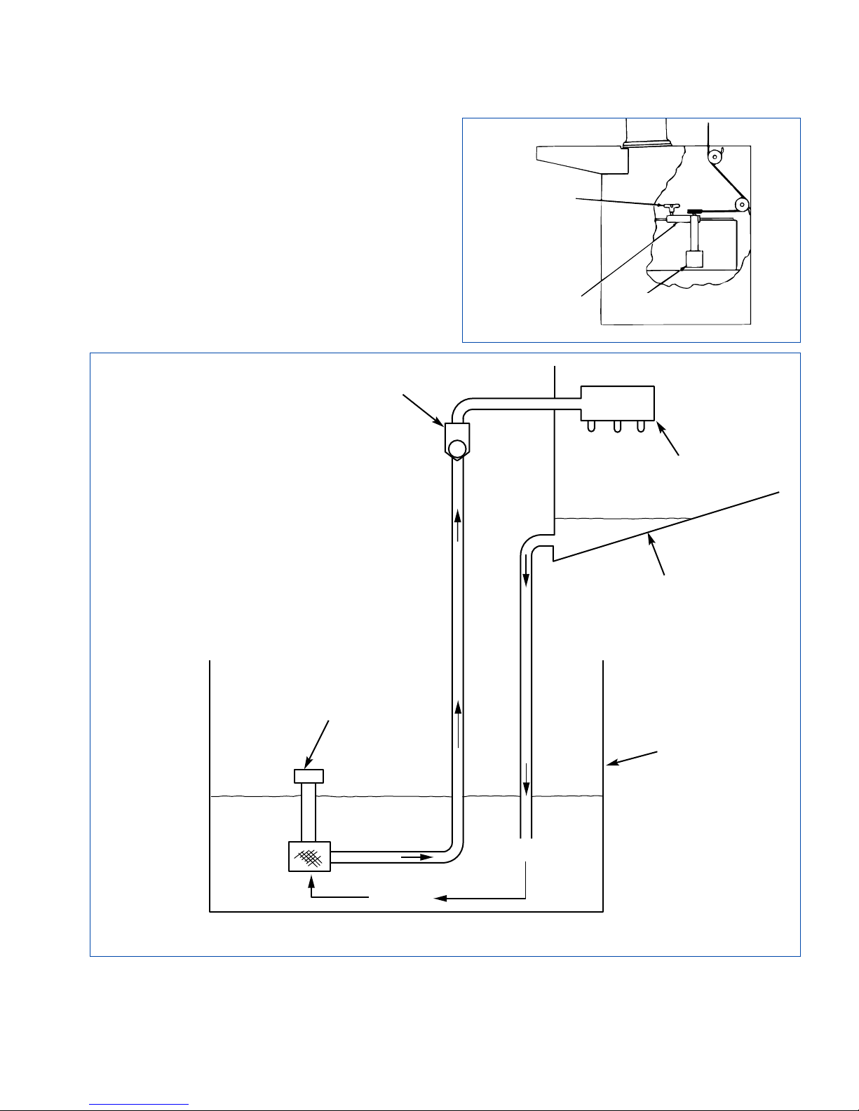
35
APPENDIX D
COOLANT FLOW DIAGRAM
PUMP
CHECK
VALV E
MACHINE
RESERVOIR
DIRTY OIL
DIRTY OIL
DIRTY OIL
MANIFOLD
TRAY
FIGURE D-1, Coolant Flow Diagram
CLAMP
KNOB
PUMP
BRACKET
PUMP
SCREEN
Page 44

NOTES
36
Page 45
37
APPENDIX E
DECLARATION OF CONFORMITY (CE)
(PAGE 1 OF 2)
SAMPLE
CE DOCUMENT
Page 46
38
APPENDIX E
DECLARATION OF CONFORMITY (CE)
(PAGE 2 OF 2)
SAMPLE
CE DOCUMENT
Page 47
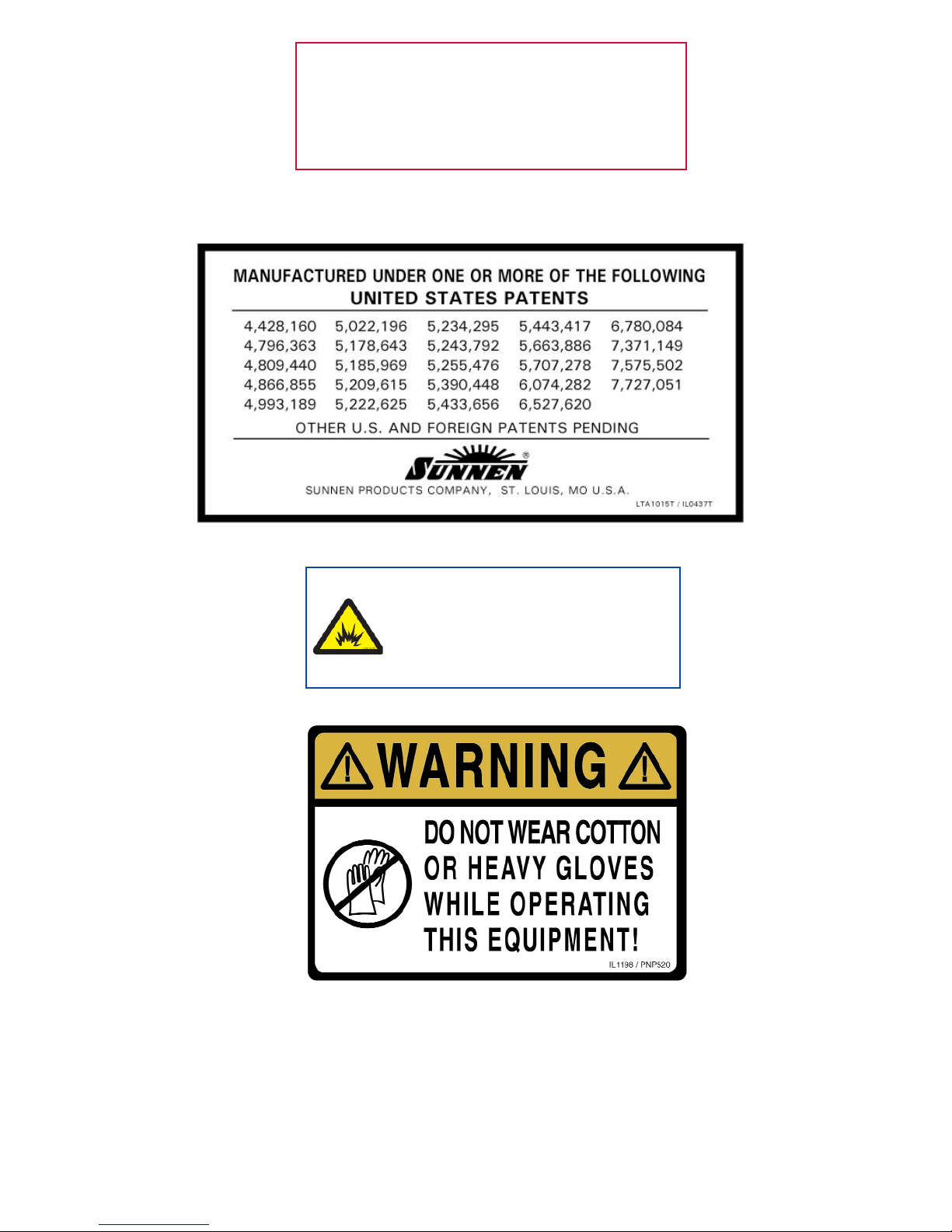
39
Like any machinery, this equipment may
be dangerous if used improperly. Be sure
to read and follow instructions for
operation of equipment.
WARNING
An Arc Flash Hazard Exists. Follow safe
work practices and wear appropriate
Personal Protective Equipment. Follow
proper lockout/tagout procedures. Failure
to comply can result in death or injury.
Page 48
FRACTION / DECIMAL / MILLIMETER EQUIVALENTS CHART
INCH
FRACTION DECIMAL
MILLIMETER
. . . . .003937 0,1000
. . . . .007874 0,2000
. . . . .011811 0,3000
1/64 .015625 0,3969
. . . . .015748 0,4000
. . . . .019685 0,5000
. . . . .023622 0,6000
. . . . .027559 0,7000
1/32 .031250 0,7938
. . . . .031496 0,8000
. . . . .035433 0,9000
. . . . .039370 1,0000
3/64 .046875 1,1906
1/16 .062500 1,5875
5/64 .078125 1,9844
. . . . .078740 2,0000
3/32 .093750 2,3813
7/64 .109375 2,7781
. . . . .118110 3,0000
1/8 .125000 3,1750
9/64 .140625 3,5719
5/32 .156250 3,9688
. . . . .157480 4,0000
11/64 .171875 4,3656
3/16 .187500 4,7625
. . . . .196850 5,0000
13/64 .203125 5,1594
7/32 .218750 5,5563
15/64 .234375 5,9531
. . . . .236220 6,0000
1/4 .250000 6,3500
17/64 .265625 6,7469
. . . . .275591
7,0000
INCH
FRACTION DECIMAL
MILLIMETER
9/32 .281250 7,1438
19/64 .296875 7,5406
5/16 .312500 7,9375
. . . . .314961 8,0000
21/64 .328125 8,3344
11/32 .343750 8,7313
. . . . .354331 9,0000
23/64 .359375 9,1281
3/8 .375000 9,5250
25/64 .390625 9,9219
. . . . .393701 10,0000
13/32 .406250 10,3188
27/64 .421875 10,7156
. . . . .433071 11,0000
7/16 .437500 11,1125
29/64 .453125 11,5094
15/32 .468750 11,9063
. . . . .472441 12,0000
31/64 .484375 12,3031
1/2 .500000 12,7000
. . . . .511811 13,0000
33/64 .515625 13,0969
17/32 .531250 13,4938
35/64 .546875 13,8906
. . . . .551181 14,0000
9/16 .562500 14,2875
37/64 .578125 14,6844
. . . . .590551 15,0000
19/32 .593750 15,0813
39/64 .609375 15,4781
5/8 .625000 15,8750
. . . . .629921 16,0000
41/64 .640625 16,2719
INCH
FRACTION DECIMAL
MILLIMETER
21/32 .656250 16,6688
. . . . .669291 17,0000
43/64 .671875 17,0656
11/16 .687500 17,4625
45/64 .703125 17,8594
. . . . .708661 18,0000
23/32 .718750 18,2563
47/64 .734375 18,6531
. . . . .748031 19,0000
3/4 .750000 19,0500
49/64 .765625 19,4469
25/32 .781250 19,8438
. . . . .787402 20,0000
51/64 .796875 20,2406
13/16 .812500 20,6375
. . . . .826772 21,0000
53/64 .828125 21,0344
27/32 .843750 21,4313
55/64 .859375 21,8281
. . . . .866142 22,0000
7/8 .875000 22,2250
57/64 .890625 22,6219
. . . . .905512 23,0000
29/32 .906250 23,0188
59/64 .921875 23,4156
15/16 .937500 23,8125
. . . . .944882 24,0000
61/64 .953125 24,2094
31/32 .968750 24,6063
. . . . .984252 25,0000
63/64 .984375 25,0031
1 1.000000 25,4000
1-1/16 1.062500 26,9880
FORMULAS:
MULTIPLY BY TO GET MULTIPLY BY TO GET
INCHES (in) x 25.4 = MILLIMETERS (mm) MILLIMETERS (mm) x 0.03937 = INCHES (in)
FEET (ft) x 0.3048 = METERS (m) METERS (m) x 3.281 = FEET (ft)
PRINTED IN U.S.A. 1208 ©COPYRIGHT SUNNEN®PRODUCTS COMPANY 2012, ALL RIGHTS RESERVED
SUNNEN PRODUCTS COMPANY
7910 Manchester Road, St. Louis, MO 63143 U.S.A.
Phone: 314-781-2100 Fax: 314-781-2268
U.S.A. Toll-Free Sales and Service:1-800-325-3670
International Division Fax: 314-781-6128
http://www.sunnen.com
e-mail: [email protected]
S
WITZERLAND
– S
UNNEN
AG
Phone: ++ 41 71 649 33 33 Fax: ++ 41 71 649 34 34
www.sunnen.ch e-mail: [email protected]
I
TALY
- S
UNNENITALIA
S.R.L.
Phone: 39 02 383 417 1 Fax: 39 02 383 417 50
www.sunnenitalia.com e-mail: [email protected]
F
RANCE
– S
UNNEN
SAS
Phone: +33 01 69 30 0000 Fax: +33 01 69 30 1111
www.sunnen.fr e-mail: [email protected]
B
ELGIUM
– S
UNNENBENELUX
BVBA
Phone: +32 38 80 28 00 Fax: +32 38 44 39 01
www.sunnen.be e-mail: [email protected]
UK – S
UNNENPRODUCTSLTD
.
Phone: ++ 44 1442 39 39 39 Fax: ++ 44 1442 39 12 12
www.sunnen.co.uk e-mail: [email protected]
P
OLAND
– S
UNNENPOLSKASP
. Z O.O.
Phone: +48 22 814 34 29 Fax: +48 22 814 34 28
www.sunnen.pl e-mail: [email protected]
R
USSIA
– S
UNNEN
RUS
Phone: +7 495 258 43 43 Fax: +7 495 258 91 75
www.sunnen.ru e-mail: [email protected]
C
ZECHREPUBLIC
– S
UNNEN
S.R.O.
Phone: +420 383 376 317 Fax: +420 383 376 316
www.sunnen.cz e-mail: [email protected]
C
HINA
– S
HANGHAISUNNENMECHANICALCO
., LTD.
Phone: 86 21 5813 3322 Fax: 86 21 5813 2299
www.sunnensh.com e-mail: [email protected]
Sunnen®reserves the right to change or
revise specifications and product design
in connection with any feature of our
products contained herein. Such changes
do not entitle the buyer to corresponding
changes, improvements, additions, or
replacements for equipment, supplies or
accessories previously sold. Information
contained herein is considered to be
accurate based on available information
at the time of printing. Should any
discrepancy of information arise, Sunnen
recommends that user verify discrepancy
with Sunnen before proceeding.
“SUNNEN®AND THE SUNNEN LOGO ARE REGISTERED TRADEMARKS OF SUNNEN PRODUCTS COMPANY.”
 Loading...