

Page 1
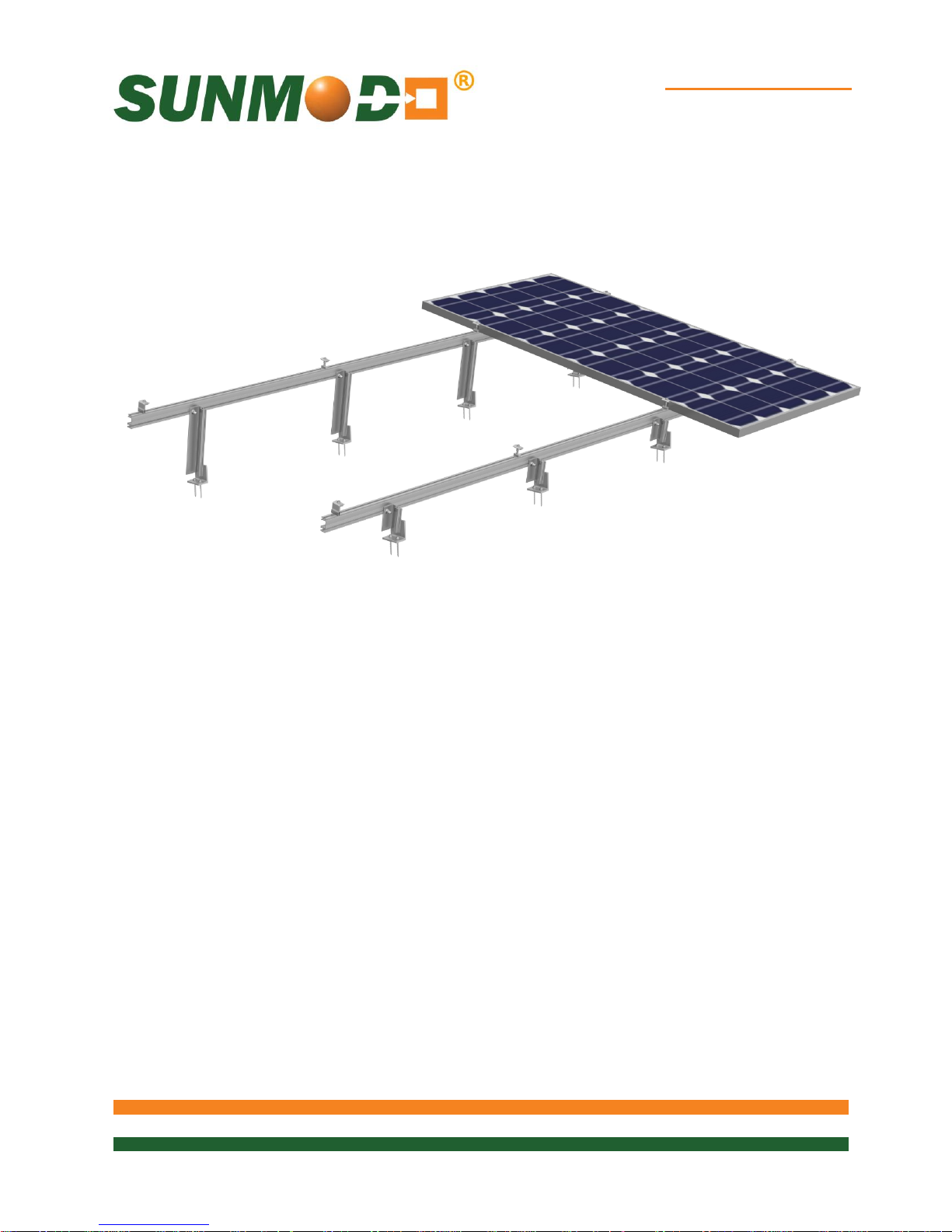
EZ Tilt-Up System
1 of 28
SunModo PV Rack Mounting System
UL2703 Compliant
Pub. D10061-V004 Copyright 2018
Page 2

EZ Tilt-Up System
2 of 28
Please read carefully before installing
Product is tested to and recognized to UL 2703 standards for safety grounding and
bonding equipment.
SunModo PV Rack Mount System can be used to mount photovoltaic (PV) panels in
a wide variety of locations. All installations shall be in accordance with NEC
requirements in the USA. The self-bonding system is for use with PV modules that
have a maximum series fuse rating of 30A. Mechanical design loads per UL 2703:
Downward Pressure: 33.42 psf (1600.2 Pa), Upward Pressure: 22.28 psf (1066.8
Pa), Down-Slope: 5 psf (239.4 Pa).
TABLE OF CONTENTS
Installer Responsibility ....................................................................................................................... 4
Safety ................................................................................................................................................ 4
SunModo Self-Bonding System ......................................................................................................... 5
EZ Tilt-Up System Components ........................................................................................................ 6
List of Compliant PV Modules .......................................................................................................... 11
Tools Required for Installation ................................................................................................ ......... 14
Torque Values for EZ Tilt-Up Components ...................................................................................... 16
EZ Tilt-Up System Overview ............................................................................................................ 17
Alternative Construction................................................................................................................... 17
Installation Instructions: ................................................................................................................... 18
Penetration Sealant System ............................................................................................................ 18
EZ Tilt-Up Assembly Example ......................................................................................................... 19
EZ Tilt-Up Tilt Angle Selection ......................................................................................................... 20
Direct L-Foot Attachment ................................................................................................................. 21
Top Mount Standoff L-Foot Attachment ........................................................................................... 22
Side Mount Standoff L-Foot Attachment .......................................................................................... 23
Rail Splice Installation – 1/4 or 3/8 ................................................................................................... 24
1/4 Rail Splice to Rail Sections ............................................................................................................. 24
3/8 Rail Splice to Rail Sections ............................................................................................................. 24
Clamp Installation – Portrait Orientation .......................................................................................... 25
End Clamp Installation .......................................................................................................................... 25
End Clamp Attachment ......................................................................................................................... 25
Page 3

EZ Tilt-Up System
3 of 28
Clamp Installation – Landscape Orientation .................................................................................... 26
Landscape End Clamp Installation ........................................................................................................ 26
Mid Clamp Installation ........................................................................................................................... 26
Ground Wire Attachment ................................................................................................................. 27
Ground Lug Installation ......................................................................................................................... 27
Rail End Covers .............................................................................................................................. 27
UL 2703 Label Placement ............................................................................................................... 28
Document Number D10061-V004
©2018 – SunModo Corp.
5001753
Page 4

EZ Tilt-Up System
4 of 28
Installer Responsibility
Before ordering and installing materials, all system layout dimensions should be confirmed by field
measurements. SunModo reserves the right to alter, without notice, any details, proposals or plans. Any
inquiries that you may have concerning installation of the PV system should be directed to your SunModo
Sales representative. Consult SunModo Sales for any information not contained in this manual. This manual
is intended to be used as a guide when installing SunModo EZ Tilt-Up systems. It is the responsibility of the
installer to ensure the safe installation of this product as outline herein.
Installer shall employ only SunModo products detail herein. The use of non SunModo components
can void the warranty and cancel the letters of UL compliance.
Installer shall guarantee that screws and anchors have adequate pullout strength and shear
capacities.
Installer shall adhere to the torque values specified in this Instruction Manual.
Installer shall use anti-seize compound, such as Permatex anti-seize, lubricant is recommended for
all threaded parts.
Installer is responsible to install solar panels over a Fire Resistant roof covering rated for the
application.
Installer is responsible to determine that the roof, its rafters, connections, and other architectural
support components can sustain the array under all code level loading conditions.
Installer shall adhere to all relevant local or national building codes. This takes account of those that
supplant this document’s requirements.
Installer shall guarantee the safe placement of all electrical details of the PV array.
Installer shall comply with all applicable local, state and national building codes, including periodic
re-inspection of the installation for loose components, loose fasteners and any corrosion, such that
if found, the affected components are to be immediately replaced.
Installer to ensure the structural support members or footings for mounting the array can withstand
all code loading conditions. Consult with licensed professional engineer for the appropriate loading
conditions.
Installer to follow all regional safety requirements during installation.
This racking system may be used to ground and/or mount a PV module complying with UL 1703
only when the specific module has been evaluated for grounding and/or mounting in compliance
with the included instructions.
Installer shall ensure bare copper grounding wire does not contact aluminum and zinc-plated steel
components to prevent risk of galvanic corrosion.
If loose components or loose fasteners are found during periodic inspection, re-tighten immediately.
If corrosion is found, replace affected components immediately.
Safety
Review relevant OSHA and other safety standards before following these instructions. The installation of
solar PV systems is a dangerous procedure and should be supervised by trained and experienced
personnel.
It is not possible for SunModo to be aware of all the possible job site situations that could cause an unsafe
condition to exist. The installer of the ground system is responsible for reading these instructions and
determining the safest way to install the ground system. These instructions are provided only as a guide to
show a knowledgeable, trained erector the correct part placement one to another. If following any of the
installation steps would endanger a worker, the erector should stop work and decide upon a corrective action.
Page 5
EZ Tilt-Up System
5 of 28
SunModo Self-Bonding System
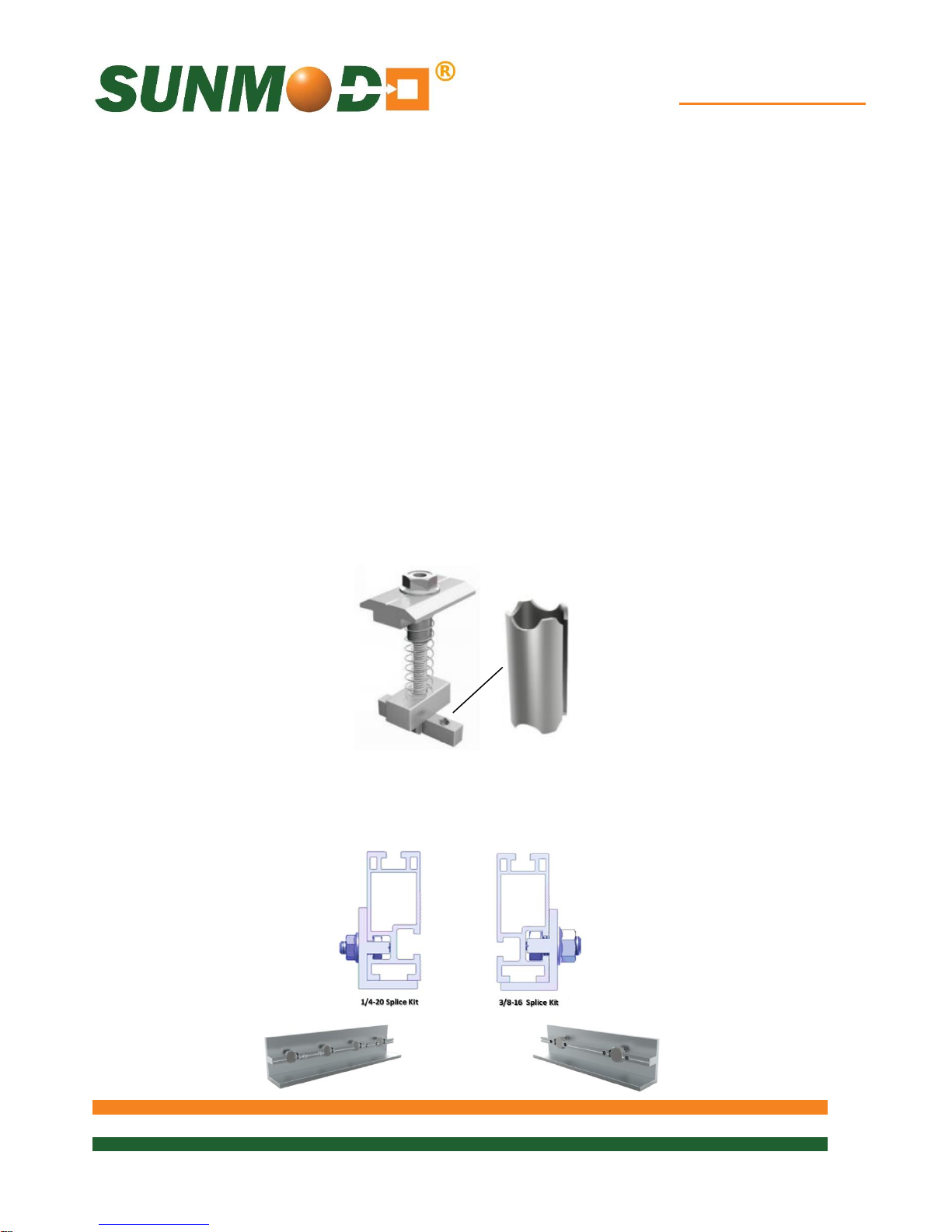
SunModo developed a proprietary grounding and bonding system that is built into the mounting
hardware for the rails, clamps and splices. We provide further grounding through all of the SunBeam
racking components including the Pipe Caps, Beams, Posts and Post Base Plates. All hardware meet
UL 2703 Grounding and Fire Standards tested by ETL.
The basis of the system is our patented stainless steel floating grounding pin which is designed to be
captive in the mounting components and provides a bonding path from the PV panel frames to the rails
and rail splices, and finally to the ground lug. The self-grounding and bonding system is for use with
PV modules that have a maximum series fuse rating of 30A. The maximum number of PV modules is
limited by the system voltage, so in a system has multiple inverters, the SunModo racking system can
theoretically go on forever.
Finally we have added a spring and Blue 242 Loctite to our Mid Clamp assemblies. The sprig keeps
the Mid Clamp in the open position ready to receive the solar module. The Blue Loctite is a light
bonding agent allowing the T-Bolt engagement into the Rail when the Collar Nut is turned from above.
The Blue Loctite has the added benefit of being an anti-seize agent for stainless steel hardware in the
area where it is applied. For additional anti-seize protection refer to the ‘Tools Required for
Installation’ section of this document.
Mid Clamp with Ground Pins
Similarly, the rail splices the grounding pins, eliminating the need for extra bonding components.
Page 6
EZ Tilt-Up System
6 of 28
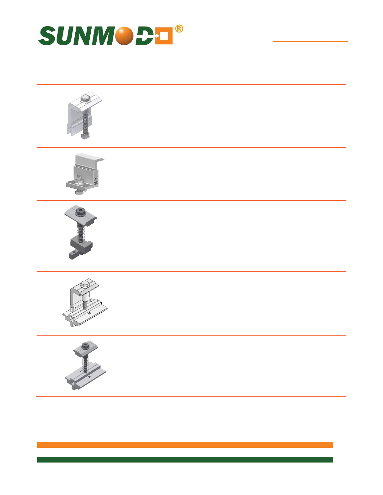
End Clamp Kit, fits panel height from
31 to 50 mm. For last 3 digits, see
table on last page.
K10224-1XX
K10224-1XX-BK
Adjustable End Clamp Kit, fits panel
height from 33 to 50 mm.
Adjustable End Clamp Kit, fits panel
height from 30 to 46 mm.
K10299-001
K10299-BK1
K10299-002
K10299-BK2
Grounding Mid Clamp Kit fits panel
height from 31 to 50 mm. For last 3
digits, see table on last page. May
be repositioned until torqued to
final value.
K10180-001
K10180-001-BK
For single-use only
Grounding End Clamp Kit with
shared rail adaptor for standard rail;
fits panel height from 31 to 50 mm.
For last 3 digits, see table on last
page. May be repositioned until
torqued to final value.
K10183-1XX
K10183-1XX-BK
For single-use only
Grounding Mid Clamp Kit with shared
rail adaptor for standard rail; fits
panel height from 31 to 50 mm. For
last 3 digits, see table on last page.
May be repositioned until torqued
to final value.
K10182-001
K10182-001-BK
For single-use only
EZ Tilt-Up System Components
Page 7
EZ Tilt-Up System
7 of 28
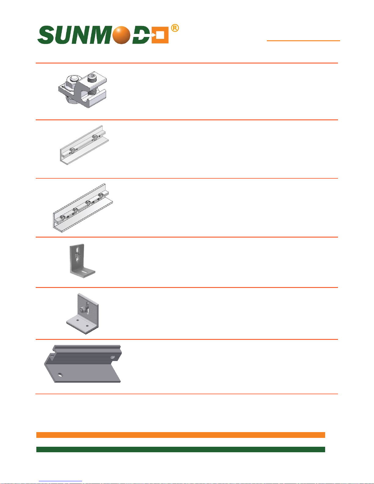
Grounding Lug Kit with Grounding
Spacer and 1/4-20 T-Bolt. May be
repositioned until torqued to final
value.
K10179-001
For single-use only
3/8” Slot Rail Splice Kit with 2X 3/816 hex bolts and flange nuts with
integral grounding. May be
repositioned until torqued to final
value.
K10178-001
K10178-BK1
HR250/HR350 3/8” Splice
For single-use only
1/4” Slot Rail Splice Kit with 4X 1/420 Bolts and Flange Nuts with
integral grounding. May be
repositioned until torqued to final
value.
K10177-001
K10177-BK1
HR250/HR350 1/4” Splice
For single-use only
L-Foot Kit (Wood Rafter Option)
K10096-001
Direct Attach L-Foot Kit (Metal
Purlin Option)
Self-tapping screws are not
provided
K10004-XXX
Tilt-Up Kit with hardware is
available in standard lengths: 8”
(front leg), and 14” or 25” (rear
leg). Last 3 digits denote rail
length. A 120” full length Tilt-Up
Rail is available for on-site cutting.
K10284-XXX (Clear)
Page 8
EZ Tilt-Up System
8 of 28
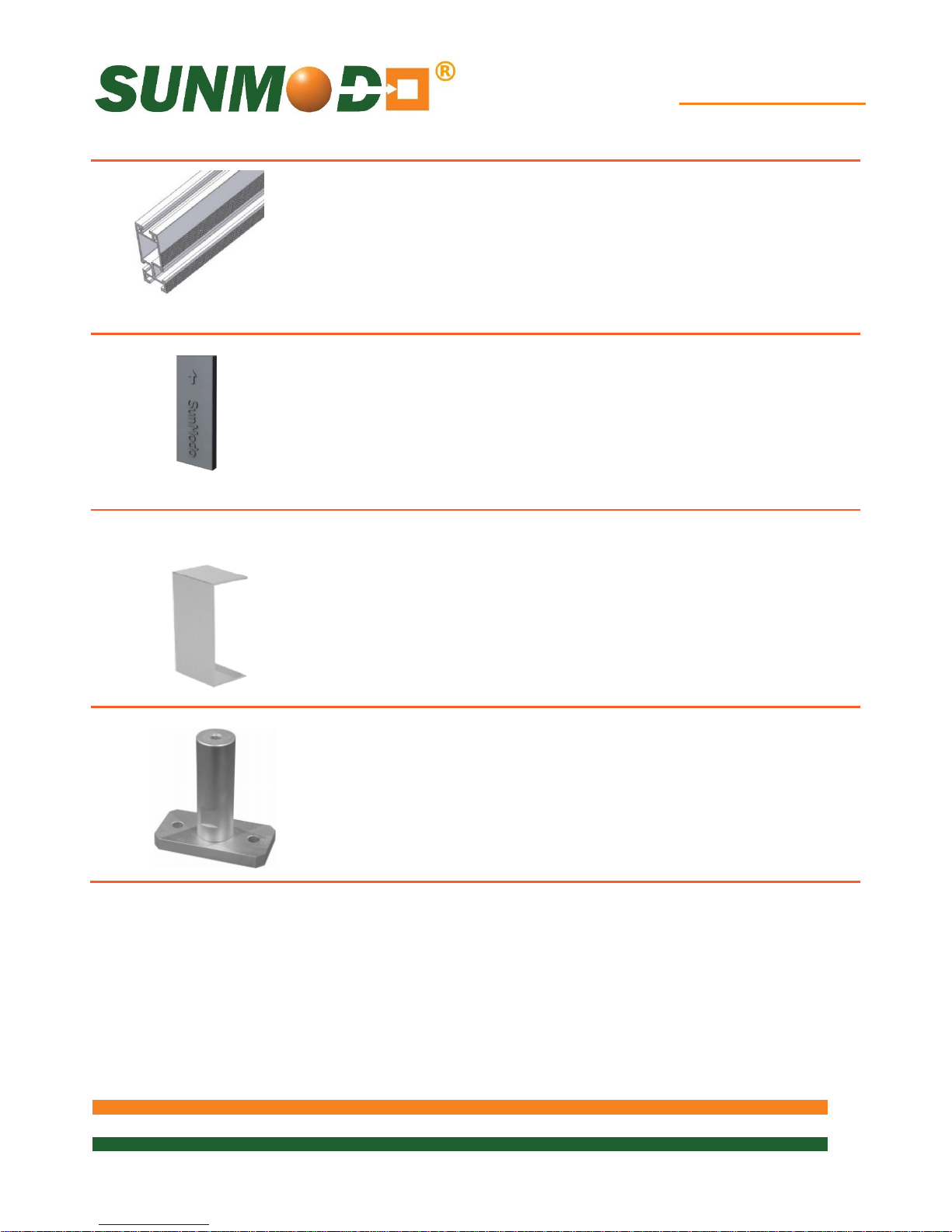
Helio Rail: Features both 1/4” and
3/8” side slots, and 1/4” top slot for
clamping PV panels. Available in 84”,
124”, 164” and 206” lengths. Last 3
digits denote rail length. 4 stock sizes
in clear and black.
A20144-XXX (Clear)
A20144-XXX-BK (Black)
HR250 (Standard Rail)
Plastic Rail End Caps available for
Helio Standard and Heavy rails
(optional)
C10017-001 (Black)
C10017-001-GR (Gray)
HR250 (Standard Rail
C10021-001 (Black)
C10021-001-GR (Gray)
HR250 (Heavy Rail)
Metal Rail End Caps available for
Helio Standard and Heavy rails
(optional)
A20284-001
A20284-BK1 (Black)
HR250 (Helio Standard)
A20285-001
HR350 (Helio Heavy)
A20263-001
HR500 (Helio Super)
Top Mount Standoff available 4”, 6”
and 8” heights
A20055-004
A20055-006
A20055-008
Page 9
EZ Tilt-Up System
9 of 28
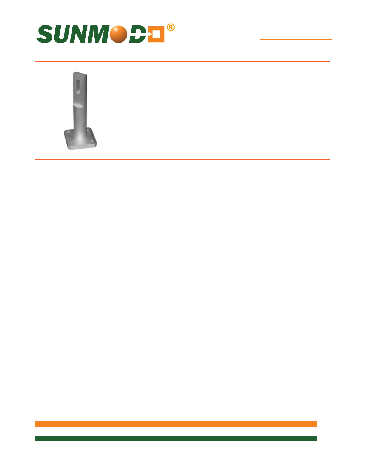
Side Mount Standoff available 5”, 7”
and 9” heights
A20055-004
A20055-006
A20055-008
Page 10
EZ Tilt-Up System
10 of 28
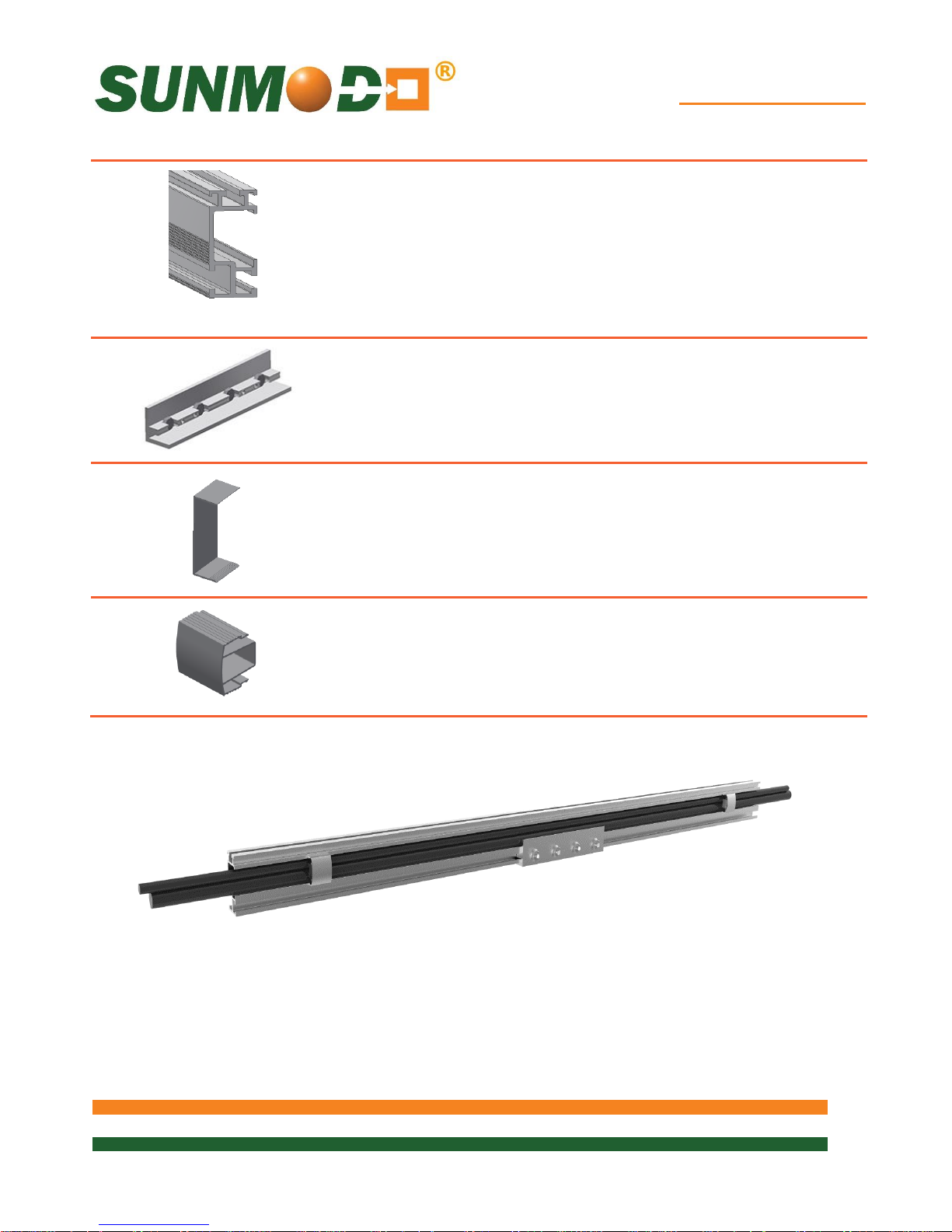
HR150 (Open Rail): Features wire
management channel and both
1/4” and 3/8” side slots, and 1/4”
top slot for clamping PV panels.
Available in 83”, 124” and 166”
lengths. Last 3 digits denote rail
length. 4 stock sizes in clear and
black.
A20242-XXX (Clear)
A20242-XXX-ML (Mill)
A20242-XXX-BK (Black)
HR150 (Open Rail)
1/4” Slot Echo Rail Splice Kit with
4X 1/4-20 Bolts and Flange Nuts
with integral grounding. May be
repositioned until torqued to
final value.
K10236-001
HR150 Splice Kit
For single-use only
Rail End Caps available for Echo
rails (optional)
A20250-001 (Clear)
A20250-BK1 (Black)
HR150 Rail End Cover
Helio Echo Rail Wire Management
Cover: snaps into the Echo rail to
manage wire bundles where
needed. Available in clear and
black.
K10239-001 (Clear)
K10239-BK1 (Black)
HR150 Wire Cover
The HR150 family of products are shown assembled above. Two HR150 Rails are
spliced together with an HR150 Rail Splice. PV electrical wires are shown routed in the
channels of the HR150 Rails, retained with two HR150 Channel Clips snapped into place.
Page 11

EZ Tilt-Up System
11 of 28
Evaluated PV Modules
Module
manufacturer
Model numbers
C-Sun
CSUN290-72P, CSUN295-72P, CSUN300-72P,
CSUN305-72P, CSUN310-72P, CSUN285-72M,
CSUN290-72M, CSUN295-72M, CSUN300-72M,
CSUN305-72M, CSUN310-72M, CSUN315-72M,
CSUN320-72M, CSUN235-60M, CSUN240-60M,
CSUN245-60M, CSUN240-60P, CSUN245-60P,
CSUN250-60P, CSUN255-60P, CSUN260-60P
Canadian Solar
CS3K-FG, CS3K-MS-FG, CS3U-MS, CS3U-MS-FG, CS3U-P, CS3U-P-FG, CS6K-M,
CS6K-MS, CS6K-MS-FG, CS6K-MS-FG, CS6K-P, CS6K-P-FG, CS6P-P, CS6P-M,
CS6U-M, CS6V-P, CS6V-M, CS6X-P
ET Solar
ET-P672300WW, ET-P672305WW, ET-P672310WW, ET-P672315WW
Hanwha Q Cells
Q.PRO L-G2 305, Q.PRO L-G2 310, Q.PRO L-G2 315
Hareon
HR-280P-24/Ba, HR-285P-24/Ba, HR-290P-24/Ba, HR-295P-24/Ba,
HR-300P-24/Ba, HR-305P-24/Ba, HR-310P-24/Ba
Hyundai
HiS-M300TI, HiS-M305TI, HiS-M310TI, HiS-M315TI, HiS-M320TI, HiS-M325TI
HiS-S325TI, HiS-S330TI, HiS-S335TI, HiS-S340TI, HiS-S345TI, HiS-S350TI
Itek Energy
IT250HE, IT255HE, IT260HE, IT265HE, IT270HE, IT275HE, IT280HE, IT285HE,
IT290HE, IT295HE, IT300HE, IT305HE, IT310HE, IT295SE, IT300SE, IT305SE,
IT310SE, IT315SE, IT350SE, IT355SE, IT360SE, IT365SE
JA Solar
JAP6 72-300/3BB, JAP6 72-305/3BB, JAP6 72-310/3BB, JAP6 72-315/3BB, JAP6 72320/3BB
Kyocera
KD315GX-LFB, KU260-6MCA, KU265-6MCA, KD255GX-LFB2, KD260GX-LFB2,
List of Compliant PV Modules
UL 2703 Qualified Modules for use with SunModo PV Racking Systems
Page 12

EZ Tilt-Up System
12 of 28
LG
LG275S1C-G4, LG280S1C-G4, LG285S1C-G4, LG300N1C-G4, LG300N1K-G4,
LG300N1T-G4, LG305N1C-G4, LG305N1K-G4, LG310N1C-G4, LG310N1K-G4,
LG310N1T-G4, LG315N1C-G4, LG320N1C-G4, LG335S2W-G4, LG340S2W-G4,
LG360N2W-B3, LG365N2W-B3, LG365N2W-G4, LG370N2W-G4, LG375N2W-G4,
LG380N2W-G4, LG385N2W-G4, LG390N2W-A5, LG395N2W-A5, LG400N2W-A5
Mitsubishi
PV-MLE270HD, PV-MLE275HD, PV-MLE280HD
Panasonic
VBHN285J40
Phono Solar Tech
PS255M-20/U, PS260M-20/U,
PS265M-20/U, PS270M-20/U,
PS275M-20/U, PS280M-20/U
PS300P-24T, PS305P-24T, PS310P-24T
PS315P-24T, PS320P-24T, PS325P-24T
Renesola
JC 255 M-24/Bbs, JC 260 M-24/Bbs, JC 265 M-24/Bbs, JC 270 M-24/Bbs,
JC 250 M-24/Bb, JC 255 M-24/Bb, JC 260 M-24/Bb,
JC 305 M-24/Abs, JC 310 M-24/Abs, JC 315 M-24/Abs, JC 320 M-24/Abs, JC 325 M-
24/Abs, JC 330 M-24/Abs, JC 335 M-24/Abs,
JC 330 S-24/Abs, JC 335 S-24/Abs, JC 340 S-24/Abs, JC 345 S-24/Abs,
JC 270 S-24/Bbs, JC 280 S-24/Bbs, JC 285 S-24/Bbs
Sanyo
HIP-190BA3, HIP-195BA3,
HIP-200BA3, HIP-205BA3,
HIT-N215A01, HIT-N220A01, HIT-N225A01
Silfab
SLA280M, SLA285M, SLA290M, SLA295M, SLA300M
SLG335M, SLG340M, SLG345M, SLG350M, SLG355M, SLG360M
SolarWorld
(V2.5 frame)
Sunmodule SW series:
SW 220 mono and poly,
SW 225 poly, SW 230 poly, SW 235 poly,
SW 240 mono and poly,
SW 245 mono and poly, SW 250 mono,
SW 255 mono, SW 260 mono, SW 265 mono, SW 270 mono
Sunmodule Plus series:
285W mono, 280W mono, 275W mono,
270W mono, 265W mono, 260W mono,
255W mono, 250W mono
Sunmodule Protect 275W mono
Sunmodule Protect 270W mono
Page 13

EZ Tilt-Up System
13 of 28
Sunmodule Protect 265W mono
Sunmodule SW 245 - 255 poly / Pro-Series
SolarWorld
(33mm frame)
Sunmodule Pro-Series:
250W poly, 255W poly, 260W poly
315W XL mono, 320W XL mono,
325W XL mono,
Sunmodule Plus:
260W mono, 270W mono, 275W mono,
280W mono, 285W mono
Stion
STO-135A, STO-140A, STO-145A, STO-150A
SunEdison
F310EzD, F315EzD, F320EzD,
F325EzD, F330EzD, F335EzD,
F310EzC, F315EzC, F320EzC,
F325EzC, F330EzC, F335EzC,
R330EzC, R335EzC, R340EzC,
R345EzC, R350EzC, R355EzC
SunPower
X21-355-BLK, X21-345, SPR-E20-327,SPR-E19-320
Trina
TSM-225 PC/PA05, TSM-230 PC/PA05,
TSM-235 PC/PA05, TSM-240 PC/PA05,
TSM-245 PC/PA05
Yingli
YL230P-29b, YL235P-29b, YL240P-29b, YL245P-29b
Page 14

EZ Tilt-Up System
14 of 28
Electric Drill or impact driver.
Note that the use of an impact driver is strongly
discouraged for all stainless nut and bolt hardware.
3/8” Socket wrench
Sockets for 3/8” drive sockets, 7/16”, 1/2”, 9/16” and 1-
1/16”
Torque Wrench 3/8” drive, 0 to 35 ft. lbs.
Anti-seize compound (Permatex 80071 or equivalent).
Tools Required for Installation
Page 15
EZ Tilt-Up System
15 of 28
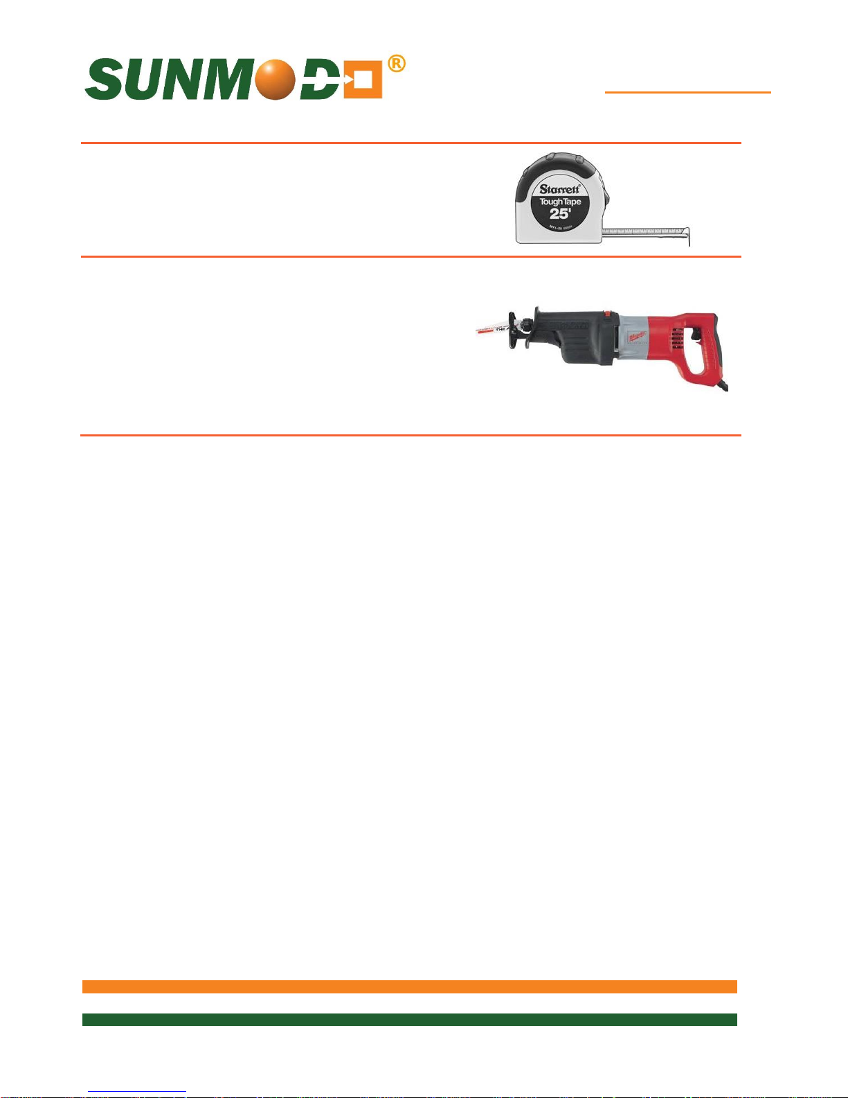
Tape measure
Saws for cutting aluminum posts and rails as
necessary
Page 16

EZ Tilt-Up System
16 of 28
Hardware
Torque lbs.
1/4-20 Bolts and Hex Flange Nut
7.5 ft. lbs.
1/4-20 Ground Lug, Flange Nut with 7/16 Hex Head
7.5 ft. lbs.
1/4-20 Ground Lug, Setscrew with 1/8 Allen drive.
4.2 ft. lbs. (50 in. lbs.)
1/4-20 Mid or End Clamp, Female Standoff with 7/16”
Hex Head Collar Nut
7.5 ft. lbs.
5/16 Lag Bolt
25 ft. lbs.
3/8-16 Bolts and Hex Flange Nuts
15 ft. lbs.
3/8-16 T-Bolts and Hex Flange Nuts
15 ft. lbs.
3/8-16 Setscrew with 3/16” Allen
10 ft. lbs.
Torque Values for EZ Tilt-Up Components
These maximum torque values must be adhered to, both for mechanical strength and to
insure the performance of the integral grounding and bonding features. It is
recommended that anti-seize compound be applied to the screw threads and a torque
wrench be used to measure the bolt torque during final assembly.
Page 17
EZ Tilt-Up System
17 of 28
EZ Tilt-Up System Overview
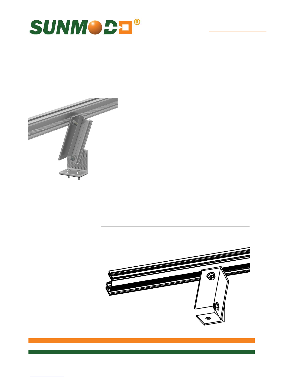
The EZ Tilt-Up System is an adjustable single module row and low point load system that
is ideal for light roof structure application. The design has an adjustable tilt leg that offers
maximum flexibility and tilt degree options that maximize power output production. The
installation is easy and quick which saves labor cost.
Flat Roof Mounting L-Foot combined with a Tilt-Up
Rail can give the system any pitch required.
SunModo offers three standard Tilt-Up Rail lengths 8
inch (front leg), and 14 or 25 inch (rear legs) in order
to achieve tilt angles of 10 and 20 degrees. A 9-foot
full length Tilt-Up Rail is available for on-site cutting.
Alternative Construction
The L-Foot, Front and Rear Tilt-Legs can be fabricated from 2 X 2 X 1/8 inch thick
aluminum angle channel. After fabricating these parts follow the instructions below to
complete the assembly.
Page 18
EZ Tilt-Up System
18 of 28
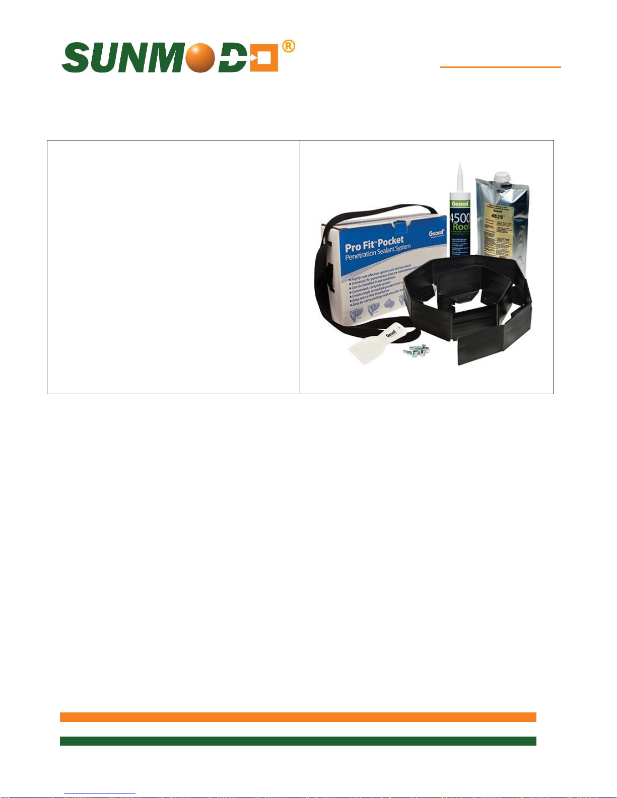
There are a variety of penetration sealing
Installation Instructions:
Penetration Sealant System
options, your roof installer should specify the
type of penetration sealant to be used.
A structural engineer should specify the type of
fastener to be used. Follow the manufacturer’s
recommendation on the installation and torque
to be used with a particular fastener type.
Page 19
EZ Tilt-Up System
19 of 28
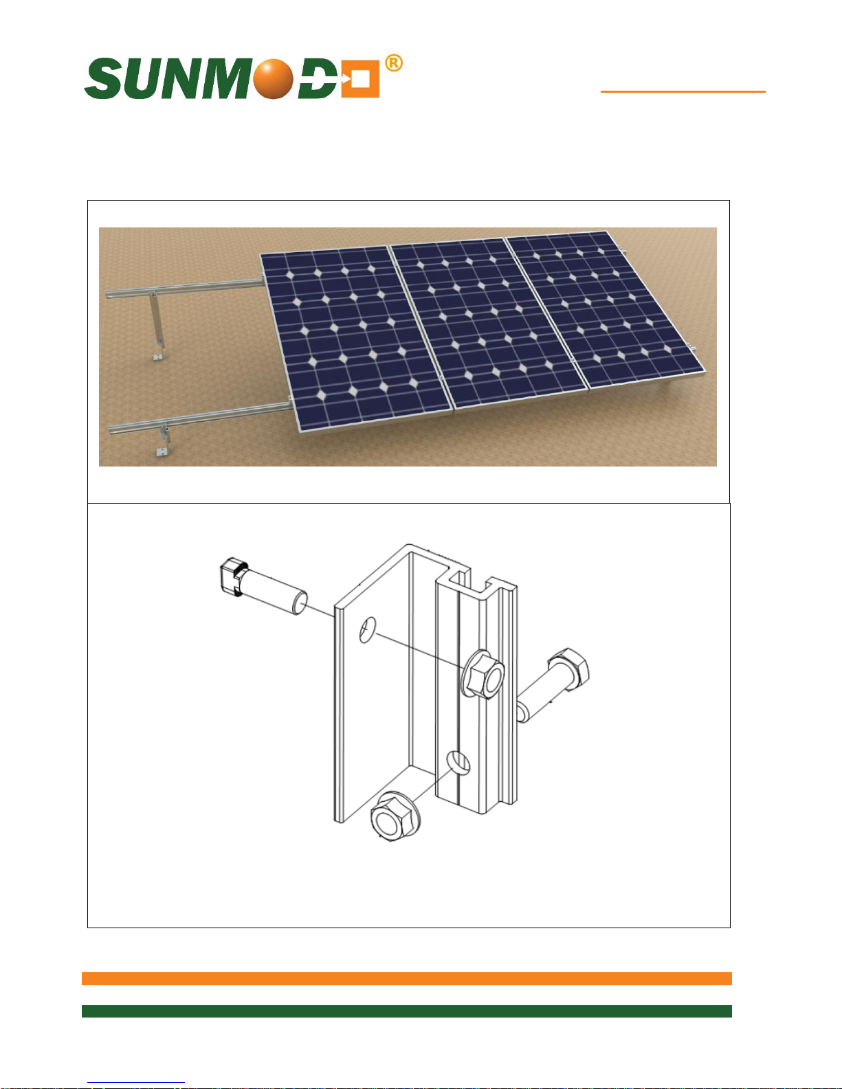
Tilt-Up Kit with hardware: K10284-XXX
EZ Tilt-Up Assembly Example
The EZ Tilt-Up shown below is just one example of the many ways the system can be configured.
Page 20
EZ Tilt-Up System
20 of 28
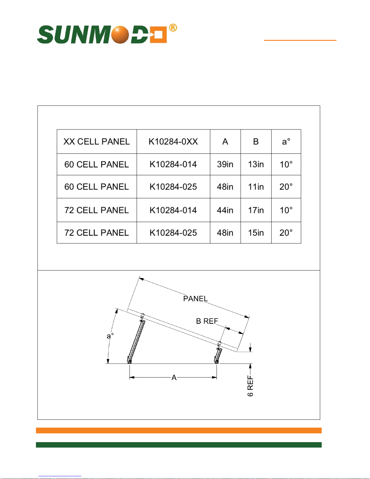
Rear Leg Selection Chart
As viewed from E-W
Dimensions are reference only
EZ Tilt-Up Tilt Angle Selection
The EZ Tilt-Up chart shown below has been provided to help you selected your desired tilt angle.
With standard Front Leg length of 8” (K10284-008) select the desired Rear Leg length using the
chart below:
Page 21
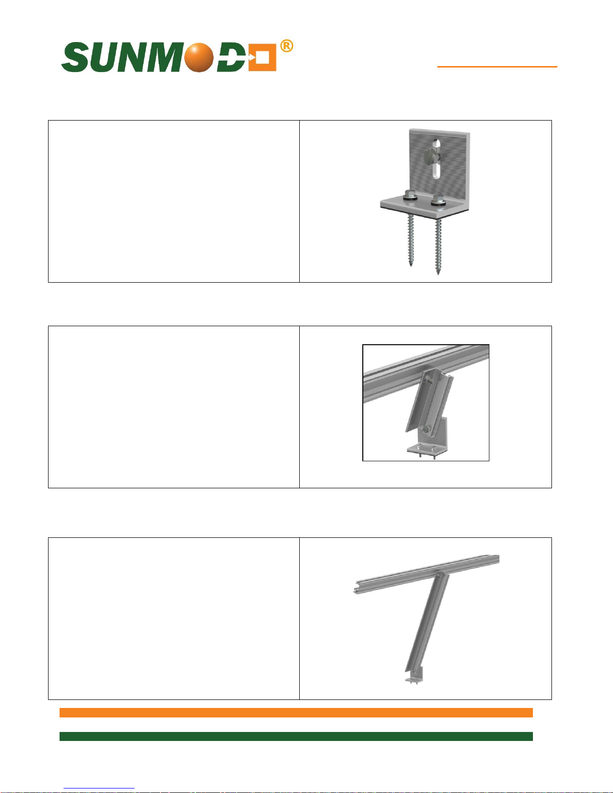
EZ Tilt-Up System
21 of 28
x 1” Bolt and 3/8-16 Flange Nut. Torque to 15 ft.
Attach the Rear Leg to the L-Foot using 3/8-16 x
Direct L-Foot Attachment
Secure the L-Foot to the roof using self-tapping
anchors. Follow the manufacturer’s
recommendation on the installation and torque
to be used with a particular fastener type.
Self-tapping anchors shown are not provided.
Front Rail Attachment
Attach the Front Leg to the L-Foot using 3/8-16
lbs.
Attach the HR150 or HR250 Rail to the Front
Leg using 3/8-16 x 1” T-Bolt and 3/8-16 Flange
Nut. Torque to 15 ft. lbs.
Rear Rail Attachment
1” Bolt and 3/8-16 Flange Nut. Torque to 15 ft.
lbs.
Attach the HR150 or HR250 Rail to the Front
Leg using 3/8-16 x 1” T-Bolt and 3/8-16 Flange
Nut. Torque to 15 ft. lbs.
Page 22
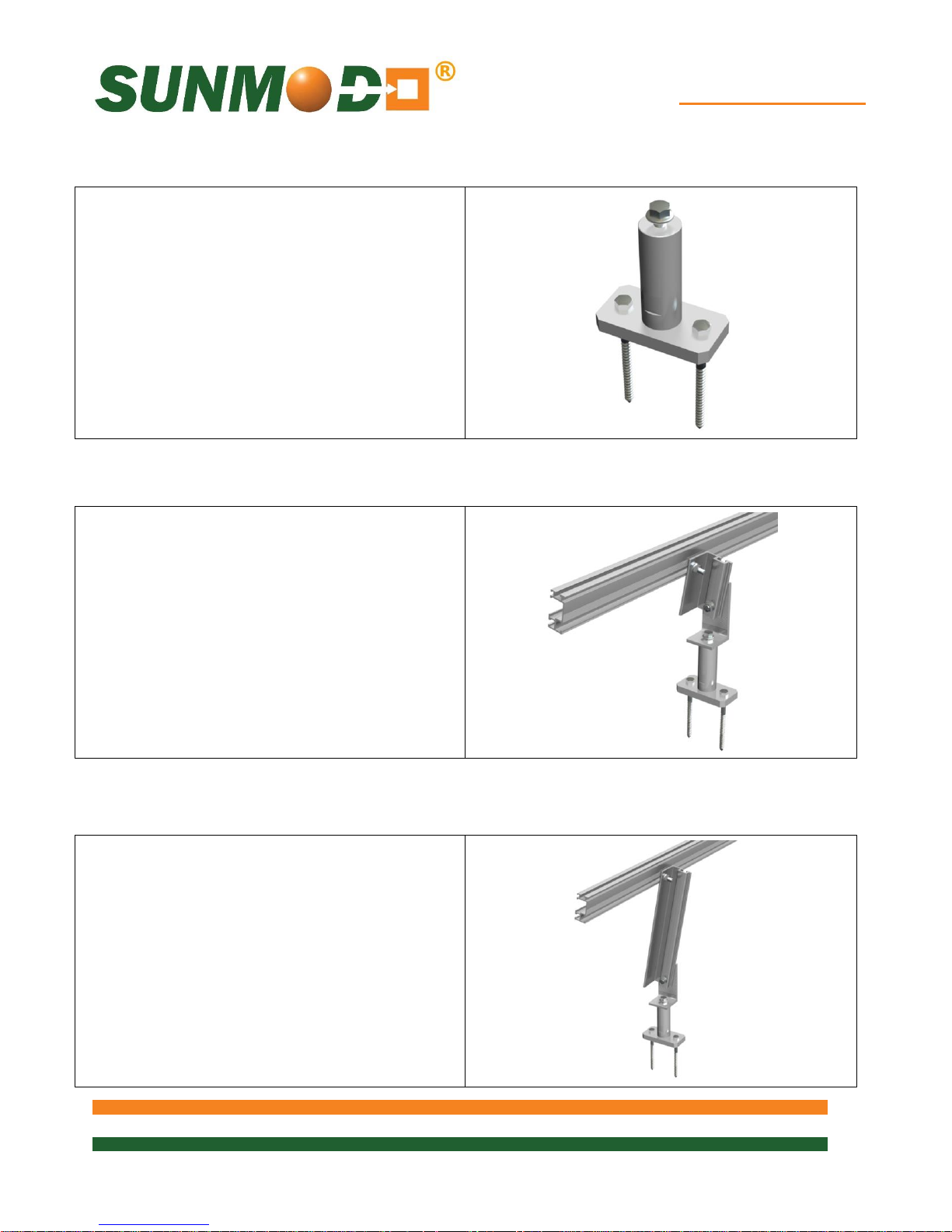
EZ Tilt-Up System
22 of 28
x 1” Bolt and 3/8-16 Flange Nut. Torque to 15 ft.
Attach the Rear Leg to the L-Foot using 3/8-16 x
Top Mount Standoff L-Foot Attachment
Secure the Top Mount Standoff to the roof
structure using 5/16 Lag Screws.
Front Rail Attachment
Attach the L-Foot to the Top Mount Standoff.
Torque to 15 ft. lbs.
Attach the Front Leg to the L-Foot using 3/8-16
lbs.
Attach the HR150 or HR250 Rail to the Front
Leg using 3/8-16 x 1” T-Bolt and 3/8-16 Flange
Nut. Torque to 15 ft. lbs.
Rear Rail Attachment
Attach the L-Foot to the Top Mount Standoff.
Torque to 15 ft. lbs.
1” Bolt and 3/8-16 Flange Nut. Torque to 15 ft.
lbs.
Attach the HR150 or HR250 Rail to the Front
Leg using 3/8-16 x 1” T-Bolt and 3/8-16 Flange
Nut. Torque to 15 ft. lbs.
Page 23
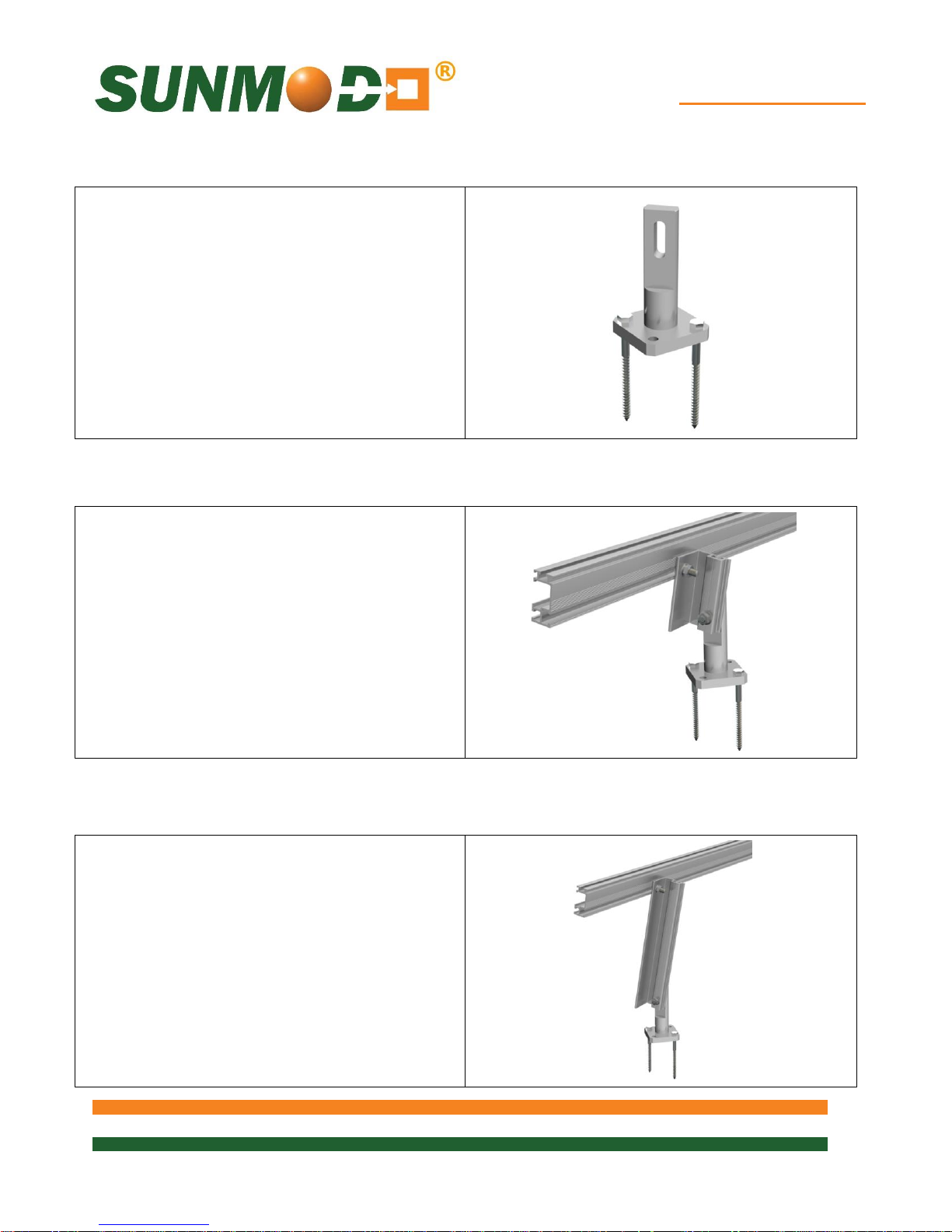
EZ Tilt-Up System
23 of 28
Side Mount Standoff L-Foot Attachment
Secure the Side Mount Standoff to the roof
structure using 5/16 Lag Screws.
Front Rail Attachment
Attach the Front Leg to the Side Mount Standoff
using 3/8-16 x 1” Bolt and 3/8-16 Flange Nut.
Torque to 15 ft. lbs.
Attach the HR150 or HR250 Rail to the Front
Leg using 3/8-16 x 1” T-Bolt and 3/8-16 Flange
Nut. Torque to 15 ft. lbs.
Rear Rail Attachment
Attach the Rear Leg to the Side Mount Standoff
using 3/8-16 x 1” Bolt and 3/8-16 Flange Nut.
Torque to 15 ft. lbs.
Attach the HR150 or HR250 Rail to the Front
Leg using 3/8-16 x 1” T-Bolt and 3/8-16 Flange
Nut. Torque to 15 ft. lbs.
Page 24
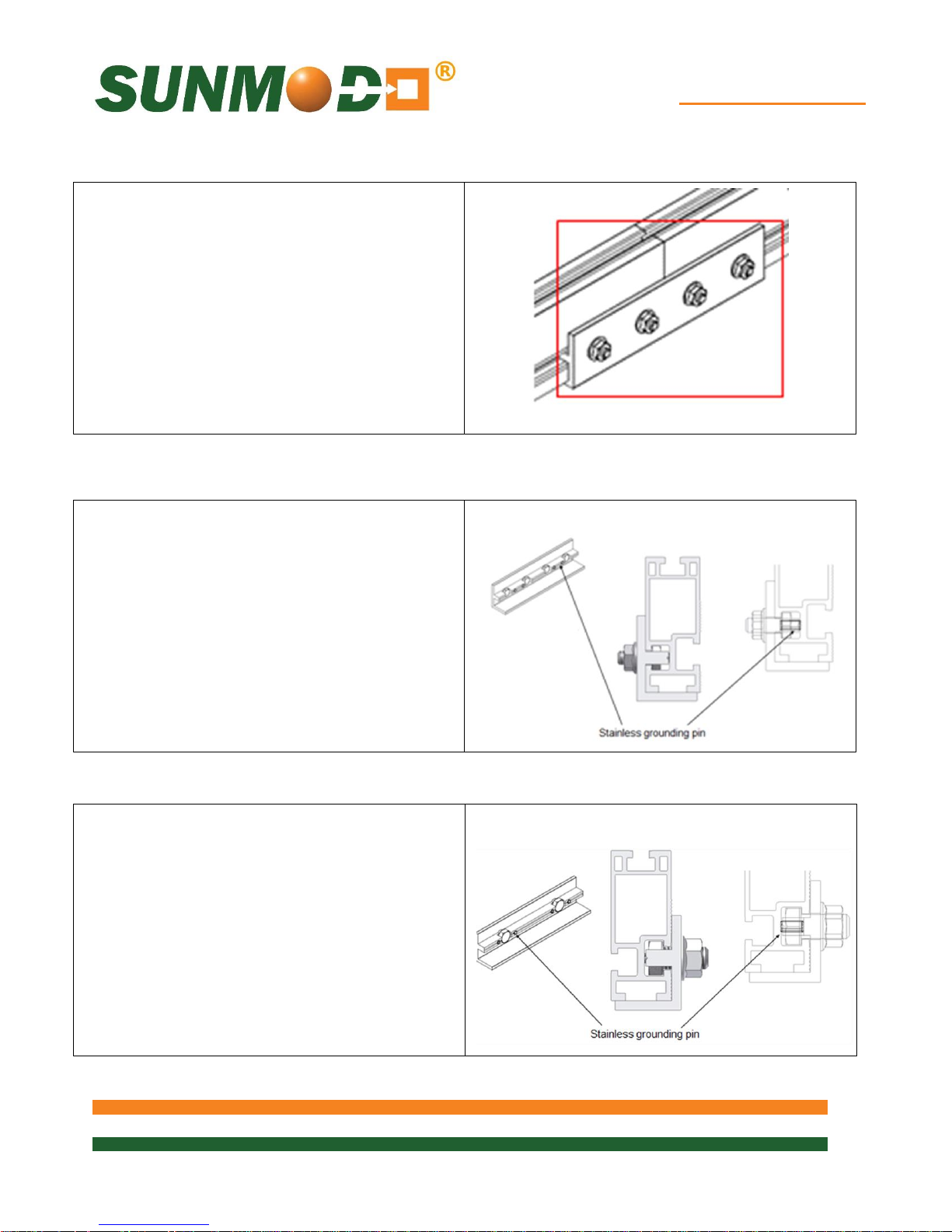
EZ Tilt-Up System
24 of 28
Where a splice is required for the Rail, the splice
Where a splice is required for the Rail, the splice
Where rail splicing is required, either the 2 bolts
Shown is the 4 bolts for the 1/4” rail slot version.
Rail Splice Installation – 1/4 or 3/8
for the 3/8” rail slot or the 4 bolts for the 1/4” rail
slots can be used.
1/4 Rail Splice to Rail Sections
should be inserted before the Rail is fastened in
place.
Slide the Rail Splice onto the end of the Rails
and center. Torque 1/4” Flange Nuts to 7.5 ft.
lbs.
3/8 Rail Splice to Rail Sections
should be inserted before the Rail is fastened in
place.
Slide the Rail Splice onto the end of the Rails
and center. Torque 3/8” Flange Nuts to 15 ft.
lbs.
Page 25
EZ Tilt-Up System
25 of 28
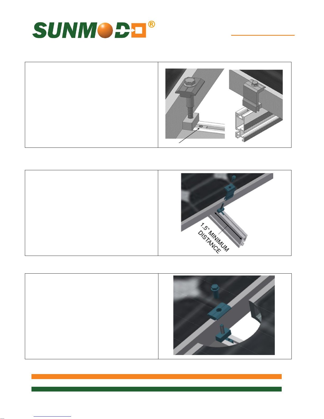
There must be a minimum of 1.5 inches of Rail
the Rails.
Insert the T-Bolt in the Rail slot and turn
Proceed with the mounting of the PV panels
Clamp Installation – Portrait Orientation
using the mid and end clamps. Specific
mounting instructions are shown in the following
sections for Portrait and Landscape mounting.
Installing Mid Clamps: A mid clamp is used
between PV panels. It will produce 1/2” spacing
between PV panel frames.
An End Clamp is used to secure PV panels at
the ends of a row.
End Clamp Installation
extending beyond the PV panel frame.
Clamp the PV panel frame by inserting the T-
Bolt into the Rail slot. Position the End Clamp
firmly against the PV panel frame and secure
using the 1/4-20 Collar Bolt. Using a 7/16”
socket, torque to 7.5 ft. lbs.
Note: When two or more PV panels are installed
grounding via the End Clamp is optional. For a
single panel configuration (shown), insert the TBolt into a T-Bolt Holder for grounding the panel to
Mid Clamp Attachment
clockwise 90° to engage the head into the slot.
Insert Grounding T-Bolt Holder to lock T-Bolt in
place.
Thread the 1/4-20 Collar Bolt onto the top of the
T-Bolt as shown. After positioning the Mid
Clamp firmly against the PV panel frame, using
a 7/16” socket, tighten to 7.5 ft. lbs.
End Clamp Attachment
Page 26
EZ Tilt-Up System
26 of 28
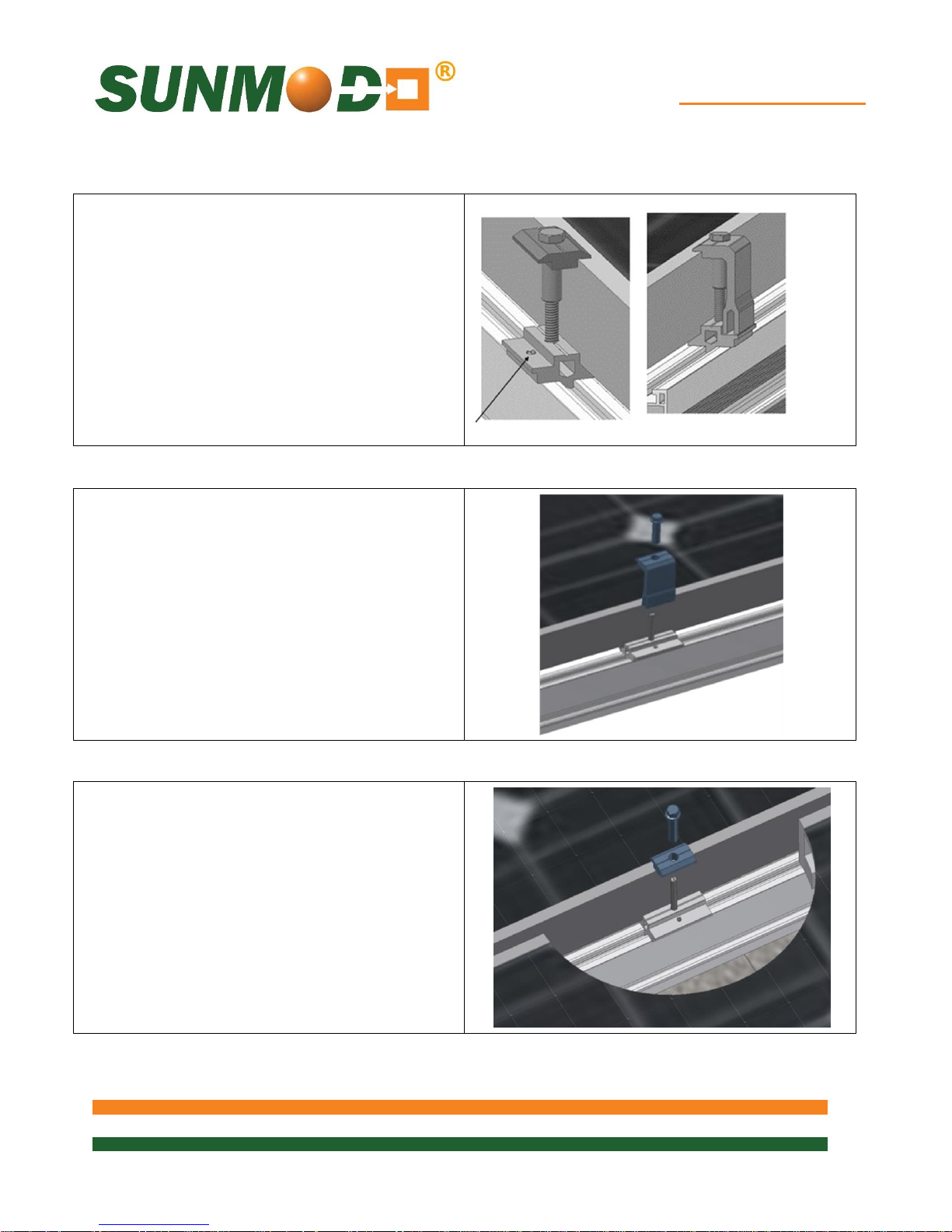
End Clamps are used at the ends of a row of PV
Insert the T-Bolt in the Rail slot and turn
Proceed with the mounting of the PV panels
Clamp Installation – Landscape Orientation
using the mid and end clamps. Specific
mounting instructions are shown in the following
sections for Portrait and Landscape mounting.
Installing Mid Clamps: A mid clamp is used
between PV panels. It will produce 1/2” spacing
between PV panel frames.
An End Clamp is used to secure PV panels at
the ends of a row.
Landscape End Clamp Installation
panels.
Insert the T-Bolt in the Rail slot and turn
clockwise 90° to engage the head into the slot.
Insert Grounding T-Bolt Holder to lock T-Bolt in
place.
Thread the 1/4” Collar Bolt onto the top of the T-
Bolt as shown. After positioning the End Clamp
firmly against the PV panel frame, using a 7/16”
socket, tighten to 7.5 ft. lbs.
Mid Clamp Installation
clockwise 90° to engage the head into the slot.
Insert Grounding T-Bolt Holder to lock T-Bolt in
place.
Thread the 1/4” Collar Bolt onto the top of the TBolt as shown. After positioning the Mid Clamp
firmly against the PV panel frame, using a 7/16”
socket, tighten to 7.5 ft. lbs.
Page 27
EZ Tilt-Up System
27 of 28
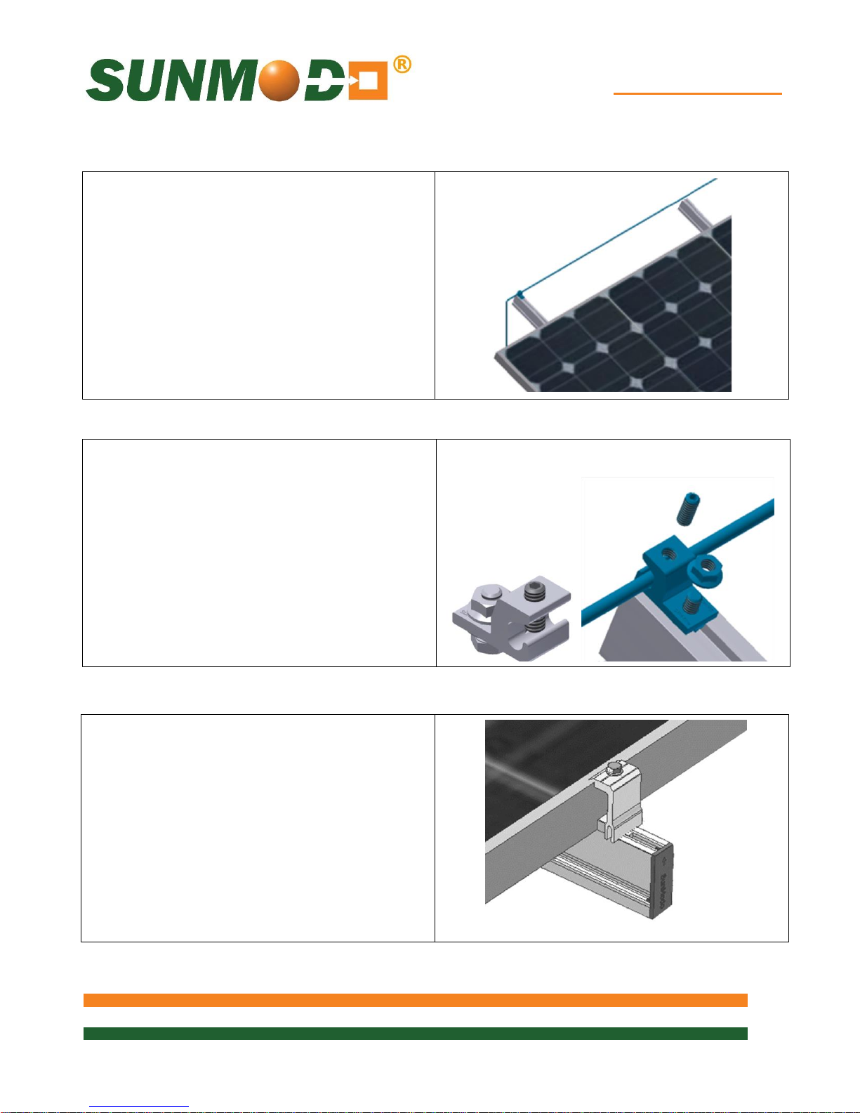
Rail End Covers can be attached to the
One Rail per row of panels should have a
installation document D10003 are available from
One Rail per row of panels should have
The picture shows a grounding lug mounted on
Ground Wire Attachment
one Rail per row of panels, and a #6 solid
copper grounding wire connecting the Ground
Lugs to the building ground per NEC 690.47.
Ground Lug Installation
Ground Lug for fastening the ground conductor
to the array. The Ground Lug is mounted on the
top or side of the Rail using a special 1/4” T-
Bolt, Grounding Spacer, and Flange Nut.
Grounding Lugs K10179-001, and detailed
SunModo separately.
Rail End Covers
mounting rails as shown.
Page 28
EZ Tilt-Up System
28 of 28
See www.sunmodo.com for current warranty documents and information.
SunModo Corporation
14800 NE 65th Street
Vancouver, WA 98682
Ph: 360-844-0048
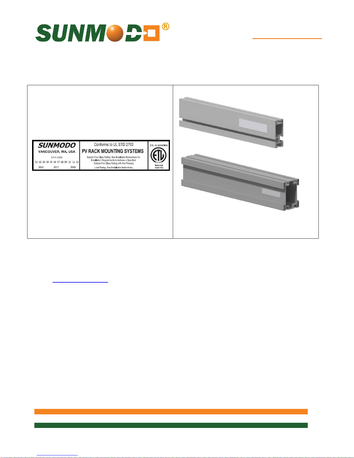
UL 2703 Label Placement
When requested the UL 2703 Label can be
located on East-West running Rail or Beam.
 Loading...