


Sun Microsystems, Inc.
www.sun.com
Submit comments about this document at: http://www.sun.com/hwdocs/feedback
Sun Ultra™ 20 M2 Workstation
Service Manual
Part No. 819-6584-11
January 2007, Revision A

Copyright ©2007 Sun Microsystems, Inc., 4150 Network Circle,Santa Clara, California 95054, U.S.A. All rights reserved.
Sun Microsystems, Inc. hasintellectual propertyrights relating to technology embodied in theproduct that is described in this document. In
particular,and without limitation, these intellectual property rightsmight include one or more of the U.S. patentslisted at
http://www.sun.com/patents and one or more additional patentsor pending patent applications in the U.S. and in other countries.
Parts ofthe product might be derived from BerkeleyBSD systems, licensed from the University ofCalifornia. UNIX is a registered trademark in
the U.S.and in other countries, exclusivelylicensed through X/Open Company, Ltd.
Sun, SunMicrosystems, the Sun logo, Java, Solaris, Sun Ultra, and NetBeans are trademarks or registered trademarks of Sun Microsystems, Inc.
in theU.S. and other countries.
AMD, Opteron, the AMDlogo, the AMD Opteron logo are trademarks or registered trademarks of Advanced Micro Devices. The PostScript
logo isa trademark or registered trademark of AdobeSystems, Incorporated.
Use ofany spare or replacement CPUs is limitedto repairor one-for-one replacement of CPUs in products exported incompliance with U.S.
export laws.Use of CPUs as product upgrades unless authorized by the U.S. Government is strictlyprohibited.
DOCUMENTATION IS PROVIDED "AS IS" AND ALL EXPRESS ORIMPLIED CONDITIONS, REPRESENTATIONS AND WARRANTIES,
INCLUDING ANYIMPLIED WARRANTY OFMERCHANTABILITY, FITNESS FOR APARTICULAR PURPOSE OR NON-INFRINGEMENT,
ARE DISCLAIMED,EXCEPT TO THE EXTENT THAT SUCHDISCLAIMERS ARE HELD TO BE LEGALLY INVALID.
U.S. GovernmentRights—Commercial use. Government users are subject tothe Sun Microsystems, Inc. standard license agreement and
applicable provisions of theFAR and its supplements.
Copyright ©2007 Sun Microsystems, Inc., 4150 Network Circle,Santa Clara, California 95054, Etats-Unis. Tous droits réservés.
Sun Microsystems, Inc. détientles droitsde propriété intellectuels relatifs à la technologie incorporée dans le produit qui est décrit dans ce
document. Enparticulier, et ce sans limitation, ces droits de propriété intellectuelle peuvent inclure un ou plus des brevets américains listés à
l'adresse http://www.sun.com/patents et un ou les brevets supplémentaires ou les applications debrevet en attente aux Etats - Uniset dans les
autres pays.
Des partiesde ce produit pourront être dérivées des systèmes BerkeleyBSD licenciés par l'Université deCalifornie. UNIX est une marque
déposée auxEtats-Unis et dans d'autres pays et licenciée exclusivement par X/Open Company, Ltd.
Sun, SunMicrosystems, le logo Sun, Java, Solaris et NetBeans Sun Ultra sont desmarques de fabrique ou des marques déposées de Sun
Microsystems, Inc. aux Etats-Unis et dans d'autres pays.
AMD, Opteron, the AMDlogo, the AMD Opteron logo are trademarks or registered trademarks of Advanced Micro Devices. Le logo PostScript
est unemarque de fabrique ou une marque déposéede Adobe Systems, Incorporated.
L'utilisation depieces detachees ou d'unites centralesde remplacement est limitee aux reparations ou a l'echange standard d'unites centrales
pour lesproduits exportes, conformement a la legislation americaine en matiere d'exportation. Sauf autorisation par les autorites des EtatsUnis, l'utilisationd'unites centrales pour proceder a des mises a jour de produits est rigoureusement interdite.
LA DOCUMENTATION EST FOURNIE "EN L'ETAT"ET TOUTESAUTRES CONDITIONS, DECLARATIONS ET GARANTIES EXPRESSES
OU TACITES SONTFORMELLEMENT EXCLUES, DANS LA MESURE AUTORISEE PAR LA LOI APPLICABLE,Y COMPRIS NOTAMMENT
TOUTE GARANTIE IMPLICITE RELATIVE A LA QUALITE MARCHANDE, A L'APTITUDEA UNE UTILISATION PARTICULIEREOU A
L'ABSENCE DECONTREFACON.

iii
Contents
Preface xi
1. Sun Ultra 20 M2 Workstation Hardware Features 1–1
1.1 Front Panel 1–2
1.2 Back Panel 1–3
1.3 Internal Components and Cables 1–4
2. Unpacking, Cabling, and Powering the Sun Ultra 20 M2 Workstation 2–1
2.1 Planning the Installation Process 2–2
2.2 Checking Package Contents 2–3
2.3 Connecting External Devices to the Workstation 2–4
2.4 Powering On the Workstation 2–6
2.5 Powering Off the Workstation 2–6
3. Troubleshooting 3–1
3.1 Troubleshooting Overview 3–1
3.2 Visual Inspection 3–2
3.2.1 Performing an External Visual Inspection 3–2
3.2.2 Performing an Internal Visual Inspection 3–2
3.3 Troubleshooting Procedures 3–3
3.4 Obtaining Technical Assistance 3–8

iv Sun Ultra 20 M2 Workstation Service Manual • January 2007
4. Running Diagnostics 4–1
4.1 Understanding the Diagnostic Partition 4–2
4.2 Starting Pc-Check Diagnostics 4–2
4.3 System Information Menu 4–3
4.4 Advanced Diagnostics 4–4
4.4.1 Hard Disk Drive Testing 4–6
4.5 Immediate Burn-In Testing 4–8
4.6 Deferred Burn-In Testing 4–10
4.7 Create Diagnostic Partition 4–11
4.7.1 Adding a Diagnostic Partition to the First Bootable Disk 4–11
4.7.2 Creating a Log File on the Diagnostic Partition 4–12
4.7.3 Accessing the Diagnostic Partition Under Red Hat Linux 4–13
4.7.4 Accessing the Diagnostic Partition Under the
Solaris 10 Operating System 4–14
4.7.5 Accessing the Diagnostic Partition Under Windows XP 4–16
4.8 Show Results Summary 4–17
4.9 Print Results Report 4–18
4.10 About Pc-Check 4–18
4.11 Exit to DOS 4–18
5. Maintaining the Workstation 5–1
5.1 Electrostatic Discharge (ESD) Precautions 5–2
5.2 Opening the Workstation 5–2
5.2.1 Tools and Supplies Needed 5–2
5.2.2 Powering Off the System and Removing the Left Side Access
Panel 5–3
5.2.3 Removing the Front Bezel 5–4
5.3 Closing the Workstation 5–5
5.3.1 Postinstallation Instructions 5–5
5.3.2 Installing the Front Bezel 5–5

Contents v
5.3.3 Installing the Left Side Access Panel 5–6
5.4 Removing or Adding a Hard Disk Drive 5–8
5.4.1 Removing a Hard Disk Drive 5–8
5.4.2 Installing a Hard Disk Drive 5–10
5.5 Installing SAS Card, Cables, and Hard Drives 5–12
5.6 Replacing the Storage Backplane 5–15
5.6.1 Removing the Storage Backplane 5–15
5.6.2 Installing the Storage Backplane 5–17
5.7 Replacing the DVD Drive 5–19
5.7.1 Removing the DVD Drive 5–19
5.7.2 Installing the DVD Drive 5–20
5.8 Removing or Installing DIMMs 5–22
5.8.1 Removing DIMMs 5–22
5.8.2 Installing DIMMs 5–23
5.8.3 Reconfiguring the System Memory 5–24
5.9 Removing and Installing a PCI-E Card 5–25
5.9.1 Removing a PCI-E Card 5–25
5.9.2 Installing a PCI-E Card 5–27
5.10 Removing and Installing PCI Cards 5–29
5.10.1 Removing a PCI Card 5–29
5.10.2 Installing a PCI Card 5–31
5.11 Replacing the System Battery 5–33
5.12 Replacing the System Fan 5–36
5.13 Replacing the Power Supply 5–38
5.13.1 Removing the Power Supply 5–38
5.13.2 Installing the Power Supply 5–41
5.14 Replacing the I/O Board Assembly 5–42
5.14.1 Removing the I/O Board Assembly 5–42

vi Sun Ultra 20 M2 Workstation Service Manual • January 2007
5.14.2 Installing the I/O Board Assembly 5–44
5.15 Replacing System Cables 5–45
5.16 Replacing the Heatsink and CPU 5–46
5.16.1 Removing the Heatsink and CPU 5–46
5.16.2 Installing a Heatsink and CPU 5–49
5.17 Replacing the Motherboard 5–53
5.17.1 Removing the Motherboard 5–53
5.17.2 Installing the Motherboard 5–56
5.18 Updating the BIOS 5–58
5.18.1 Flashing the BIOS 5–58
5.18.2 Resetting Previous BIOS Settings 5–59
A. System Specifications A–1
A.1 System Components and Features A–2
A.2 Memory Configurations A–3
A.3 PCI-E and PCI Expansion Slots A–4
A.4 Physical Specifications A–4
A.5 Power Specifications A–5
A.6 Environmental Specifications A–6
B. BIOS POST Codes B–1
Index Index–1

vii
Figures
FIGURE 1-1 Front Panel Components 1–2
FIGURE 1-2 Back Panel Components 1–3
FIGURE 1-3 Internal System Components 1–4
FIGURE 1-4 Power Supply and Component Cable Connections to Motherboard 1–5
FIGURE 2-1 Process Flow for Setting Up the Sun Ultra 20 M2 Workstation 2–2
FIGURE 2-2 External Cable Connections 2–4
FIGURE 2-3 Connecting the Monitor to the System 2–5
FIGURE 5-1 Removing the Side Access Panel 5–3
FIGURE 5-2 Removing the Front Bezel 5–4
FIGURE 5-3 Installing the Front Bezel 5–6
FIGURE 5-4 Installing the Left Side Access Panel 5–7
FIGURE 5-5 Removing a Hard Disk Drive 5–9
FIGURE 5-6 Installing a Hard Disk Drive 5–11
FIGURE 5-7 Installing a SAS Card 5–13
FIGURE 5-8 Location of the Storage Backplane 5–15
FIGURE 5-9 Removing the Storage Backplane 5–16
FIGURE 5-10 Installing the Storage Backplane 5–17
FIGURE 5-11 Removing the DVD Drive 5–19
FIGURE 5-12 Installing the DVD Drive 5–20
FIGURE 5-13 Location of Power and IDE Cables 5–21

viii Sun Ultra 20 M2 Workstation Service Manual • January 2007
FIGURE 5-14 DIMM Locations 5–22
FIGURE 5-15 Removing a DIMM 5–23
FIGURE 5-16 Installing a DIMM 5–24
FIGURE 5-17 Removing a PCI-E Graphics Card 5–26
FIGURE 5-18 Installing a PCI-E Graphics Card 5–28
FIGURE 5-19 Removing a PCI Card 5–30
FIGURE 5-20 Installing a PCI card 5–32
FIGURE 5-21 Removing the System Battery 5–34
FIGURE 5-22 Installing a System Battery 5–35
FIGURE 5-23 Removing the System Fan 5–36
FIGURE 5-24 Installing the System Fan 5–37
FIGURE 5-25 Location of the Power Supply 5–38
FIGURE 5-26 Locations of Power Supply Connections on the Motherboard 5–39
FIGURE 5-27 Removing the Power Supply From the Chassis 5–40
FIGURE 5-28 Installing the Power Supply Into the Chassis 5–41
FIGURE 5-29 Removing the I/O Board Assembly 5–43
FIGURE 5-30 Installing the I/O Board Assembly 5–44
FIGURE 5-31 Unlatching the Heatsink/Fan Assembly 5–47
FIGURE 5-32 Removing the Heatsink/Fan Assembly From the Motherboard 5–48
FIGURE 5-33 Removing the CPU From the Workstation 5–49
FIGURE 5-34 Installing the CPU 5–50
FIGURE 5-35 Installing the Heatsink/Fan Assembly 5–51
FIGURE 5-36 Securing the Heatsink/Fan Assembly Latches 5–52
FIGURE 5-37 Removing the Nine Motherboard Screws 5–54
FIGURE 5-38 Removing the Motherboard From the Chassis 5–55
FIGURE 5-39 Installing the Motherboard 5–57
FIGURE B-1 Location of Port 80 LED B–1

ix
Tables
TABLE 1-1 Front Panel Components 1–2
TABLE 1-2 Back Panel Components 1–3
TABLE 1-3 Internal System Components 1–4
TABLE 1-4 Power Supply and Component Cable Connections to Motherboard 1–5
TABLE 2-1 Items Included in the Sun Ultra 20 M2 Workstation Box 2–3
TABLE 3-1 Troubleshooting Procedures 3–4
TABLE 3-2 Sun Web Sites and Telephone Numbers 3–8
TABLE 4-1 System Information Menu Options 4–3
TABLE 4-2 Advanced Diagnostics Tests Menu Options 4–4
TABLE 4-3 Parameters for the HDD Tests 4–7
TABLE 4-4 Continuous Burn-in Testing Options 4–8
TABLE 4-5 Show Results Summary 4–17
TABLE 5-1 Battery Specifications 5–33
TABLE 5-2 Power Supply Cable Connections 5–39
TABLE A-1 Sun Ultra 20 M2 Workstation Components A–2
TABLE A-2 Sun Ultra 20 M2 Workstation Memory Configurations A–3
TABLE A-3 Internal Expansion Slots A–4
TABLE A-4 Sun Ultra 20 M2 Workstation Physical Specifications A–4
TABLE A-5 Input Voltage Range A–5
TABLE A-6 Input Frequency Range A–5

x Sun Ultra 20 M2 Workstation Service Manual • January 2007
TABLE A-7 Input Current A–5
TABLE A-8 Sun Ultra 20 M2 Workstation Environmental Specifications A–6
TABLE B-1 BIOS Port 80 POST Codes B–2

xi
Preface
The Sun Ultra 20 M2 Workstation Service Manual provides a detailed description of
the hardware and software applications used to support the Sun Ultra 20 M2
Workstation. This book is intended for system administrators, network
administrators, or service technicians who have knowledge of workstation hardware
and software.
How this Document is Organized
Chapter 1 provides an overview of the Sun Ultra 20 M2 Workstation.
Chapter 2 describes how to connect external cables and power on or off the
workstation.
Chapter 3 provides visual inspection and troubleshooting procedures.
Chapter 4 describes how to run diagnostics and remove or replace the diagnostic
partition.
Chapter 5 describes how to remove and replace components.
Appendix A contains information on system specifications.
Appendix B contains information on BIOS POST codes.

xii Sun Ultra 20 M2 Workstation Service Manual • January 2007
Shell Prompts
Typographic Conventions
Shell Prompt
C shell machine-name%
C shell superuser machine-name#
Bourne shell and Korn shell $
Bourne shell and Korn shell superuser #
Typeface
*
* The settings on your browser might differ from these settings.
Meaning Examples
AaBbCc123 The names of commands, files,
and directories; on-screen
computer output
Edit your.login file.
Use ls -a to list all files.
% You have mail.
AaBbCc123
What you type, when contrasted
with on-screen computer output
% su
Password:
AaBbCc123 Book titles, new words or terms,
words to be emphasized.
Replace command-line variables
with real names or values.
Read Chapter 6 in the User’s Guide.
These are called class options.
You must be superuser to do this.
To delete a file, type rm filename.

Preface xiii
Related Documentation
The document set for the Sun Ultra 20 M2 Workstation is described in the Where To
Find Sun Ultra 20 M2 Workstation Documentation sheet that is packed with your
system. All documents are posted at the product’s documentation site; see the
following URL:
http://www.sun.com/documentation
Translated versions of some of these documents are available at the product’s
documentation site in Simplified Chinese, Traditional Chinese, French, German,
Italian, Japanese, Korean, and Spanish.
English documentation is revised more frequently and might be more up-to-date
than the translated documentation.
Documentation, Warranty, Support, and
Training URLs
Sun Function URL Description
Hardware
Documentation
http://www.sun.com/documentation Sun hardware documentation
Software
Documentation
http://docs.sun.com Solaris OS and other software
documentation
Warranty http://www.sun.com/service/support/
warranty/index.html
View specific details regarding your
warranty
Support http://www.sun.com/support/ Obtain technical support, including
patches
Training http://www.sun.com/training/ Learn about Sun courses and educational
offerings

xiv Sun Ultra 20 M2 Workstation Service Manual • January 2007
Ordering Components
You can order additional components and replacement parts for the Sun Ultra 20 M2
Workstation. Contact your local Sun sales representative for more information. For
the most up-to-date component information, see the Sun Ultra 20 M2 Workstation
components list at:
http://sunsolve.sun.com/handbook_pub/
Third-Party Web Sites
Sun is not responsible for the availability of third-party web sites mentioned in this
document. Sun does not endorse and is not responsible or liable for any content,
advertising, products, or other materials that are available on or through such sites
or resources. Sun will not be responsible or liable for any actual or alleged damage
or loss caused by or in connection with the use of or reliance on any such content,
goods, or services that are available on or through such sites or resources.
Safety Information
Read the following documents for safety information:
■ Important Safety Information for Sun Hardware Systems, 816-7190
■ Sun Ultra 20 M2 Workstation Safety and Compliance Guide, 819-2149

Preface xv
Sun Welcomes Your Comments
Sun is interested in improving its documentation and welcomes your comments and
suggestions. You can submit your comments by going to:
http://www.sun.com/hwdocs/feedback/
Please include the title and part number of your document with your feedback: Sun
Ultra 20 M2 Workstation Service Manual, 819-6584-11.

xvi Sun Ultra 20 M2 Workstation Service Manual • January 2007

1-1
CHAPTER
11
Sun Ultra 20 M2 Workstation
Hardware Features
This chapter provides an overview of the Sun Ultra 20 M2 Workstation hardware
features, and includes the following sections:
■ Section 1.1, “Front Panel” on page 1-2
■ Section 1.2, “Back Panel” on page 1-3
■ Section 1.3, “Internal Components and Cables” on page 1-4

1-2 Sun Ultra 20 M2 Workstation Service Manual • January 2007
1.1 Front Panel
FIGURE 1-1 illustrates the front panel of the Sun Ultra 20 M2 Workstation. TABLE 1-1
lists the components called out in the figure.
FIGURE 1-1 Front Panel Components
TABLE 1-1 Front Panel Components
Label Button/LED/Port Label Button/LED/port
1 Power button 4 Two USB 2.0 ports
2 Power LED 5 Microphone-in jack
3 Two 1394 ports 6 Headphone-out jack

Chapter 1 Sun Ultra 20 M2 Workstation Hardware Features 1-3
1.2 Back Panel
FIGURE 1-2 depicts the back panel of the Sun Ultra 20 M2 Workstation. TABLE 1-2 lists
the components called out in the figure.
FIGURE 1-2 Back Panel Components
TABLE 1-2 Back Panel Components
Label Connector/Slot Label Connector/Slot
1 Power connector 8 Four USB 2.0 connectors
2 Power switch 9 PCI Express x16 graphics slot
3 Onboard DB15 VGA graphics
connector (for ES 1000 graphics
controller)
10 PCI Express x1 slot
4 Line-in jack 11 PCI Express x16 mechanical slot
(x8 electrical)
5 Line-out jack 12 Three PCI 33-MHz 32-bit slots
6 Microphone jack 13 Cover plate, no slot
7 Two Ethernet connectors

1-4 Sun Ultra 20 M2 Workstation Service Manual • January 2007
1.3 Internal Components and Cables
FIGURE 1-3 shows the location for major system components and connectors.
TABLE 1-3 lists the components called out in the figure.
FIGURE 1-3 Internal System Components
TABLE 1-3 Internal System Components
Label Component Label Component
1 Power supply 6 DVD release lever
2 Memory (DIMMs) 7 I/O board release thumbscrew
3 System fan 8 Heatsink release lever
4 PCI Express slots (3) numbered
PCI-E slot 0 (top) to PCI-E slot 2
9 System serial number
5 PCI slots (3) numbered PCI slot 0
(top) to PCI slot 2
10 Hard disk drive(s)

Chapter 1 Sun Ultra 20 M2 Workstation Hardware Features 1-5
FIGURE 1-4 shows the cable connections on the motherboard. TABLE 1-4 lists the
components called out in the figure.
FIGURE 1-4 Power Supply and Component Cable Connections to Motherboard
TABLE 1-4 Power Supply and Component Cable Connections to Motherboard
Label Cable Connection Label Cable Connection
1 Power supply 3 to DVD drive 8 DVD drive to motherboard IDE
2 DVD drive analog to motherboard J8 9 I/O board J5 to motherboard USB 3
3 I/O board J1 to motherboard J7 10 Storage backplane HDD2 to motherboard SATA 2
4 Power supply P2 to motherboard PWR2 11 Storage backplane HDD1 to motherboard SATA 1
5 Power supply P1 to motherboard PWR1 12 I/O board J12 to motherboard FPB
6 System fan to motherboard SYS_FAN 13 I/O board J8 to motherboard 1394-1 and 1394-2
7 Power supply P4 to storage backplane J3 14 CPU fan to motherboard CPU_FAN

1-6 Sun Ultra 20 M2 Workstation Service Manual • January 2007

2-1
CHAPTER
22
Unpacking, Cabling, and Powering
the Sun Ultra 20 M2 Workstation
This chapter describes how to connect cables and power the Sun Ultra 20 M2
Workstation on and off. The chapter includes the following sections.
■ Section 2.1, “Planning the Installation Process” on page 2-2
■ Section 2.2, “Checking Package Contents” on page 2-3
■ Section 2.3, “Connecting External Devices to the Workstation” on page 2-4
■ Section 2.4, “Powering On the Workstation” on page 2-6
■ Section 2.5, “Powering Off the Workstation” on page 2-6

2-2 Sun Ultra 20 M2 Workstation Service Manual • January 2007
2.1 Planning the Installation Process
Use the following flowchart to assist you with installing the Sun Ultra 20 M2
Workstation.
FIGURE 2-1 Process Flow for Setting Up the Sun Ultra 20 M2 Workstation
Ye s
No
No
Install
optional
components.
Ye s
See Chapter 1.
To install DIMMs, a graphic
accelerator, PCI/PCI-E
cards, hard drives, or a
DVD drive, see Chapter 2.
See Section 2.4, “Powering On the
Workstation” on page 2-6.
See the Sun Ultra 20 M2 Workstation
Installation Guide.
Install your
OS.
To install an optional,
supported OS, see the Sun
Ultra 20 M2 Workstation
Operating System Installation
Guide.
See Section 2.3, “Connecting
External Devices to the
Workstation” on page 2-4.
Unpack the workstation and
familiarize yourself with the
workstation features.
Connect the workstation and
external device cables.
Power on the workstation.
Configure
preinstalled
OS
software?
Configure the preinstalled Solaris 10
Operating System.
Install
optional
components?
READY TO WORK!
START

Chapter 2 Unpacking, Cabling, and Powering the Sun Ultra 20 M2 Workstation 2-3
2.2 Checking Package Contents
Carefully unpack all workstation components from the packing cartons. The
following items are contained in the package.
A country kit is optional, ships in a separate package, and includes a power cable,
keyboard, and mouse.
TABLE 2-1 Items Included in the Sun Ultra 20 M2 Workstation Box
Hardware • Sun Ultra 20 M2 Workstation
• DMS-59 cable
(if the workstation is configured with an NVS285 graphics card)
Documentation
*
* Depending on the system configuration ordered, some systems might not include documentation or the Tools
and Drivers CD.
• Sun Ultra 20 M2 Workstation Installation Manual
• Where to Find Sun Ultra 20 M2 Workstation Documentation
(lists available online documents for this product)
• Sun safety and license documents
• Welcome letter
CD-ROM • Sun Ultra 20 M2 Workstation Tools and Drivers CD
(includes drivers and diagnostics software)

2-4 Sun Ultra 20 M2 Workstation Service Manual • January 2007
2.3 Connecting External Devices to the
Workstation
FIGURE 2-2 illustrates the external device cable connections to the workstation.
FIGURE 2-2 External Cable Connections
Perform this procedure to connect external devices to the workstation.
1. Connect the workstation power cord to a grounded electrical outlet.
2. Connect the keyboard to a USB connector on the back or front panel.
3. Connect the mouse to the USB connector on the underside of the keyboard or to a
USB connector on the front or back panel.
4. Connect the Ethernet cable to either Ethernet connector on the Sun Ultra 20 M2
Workstation, and connect the other end of the cable to an Ethernet RJ-45 jack.

Chapter 2 Unpacking, Cabling, and Powering the Sun Ultra 20 M2 Workstation 2-5
5. Connect the monitor cable as follows:
■ If a PCI Express graphics card is not installed in the top PCI-E slot, connect the
monitor to the onboard video connector. See the top of
FIGURE 2-3.
■ If a PCI Express graphics card is installed in the top PCI-E slot, connect the
monitor to the graphics card connector. See the bottom of
FIGURE 2-3.
Your graphics card might require a DVI cable to connect to your monitor.
FIGURE 2-3 Connecting the Monitor to the System
6. Connect any additional external devices to the workstation’s other connectors.

2-6 Sun Ultra 20 M2 Workstation Service Manual • January 2007
2.4 Powering On the Workstation
Perform this procedure to power on the workstation.
1. Turn on the power to the monitor and to all external devices.
2. Turn the power switch on the rear of the workstation to the On ( | ) position.
3. Press and release the power switch on the front panel.
4. After several seconds, verify that the platform power LED next to the power
switch is lit.
The platform power LED lights after the workstation begins the internal booting
process.
5. If you need to change the system parameters in the BIOS, press the F2 key during
the POST process to access the BIOS Setup Utility.
Caution – Be careful when making changes to the system BIOS, as some changes
can cause your system to malfunction.
2.5 Powering Off the Workstation
1. Save your data and close any open applications.
2. Read both of the following power-off options, and then follow one of the options
to turn off the workstation.
■ Power off the workstation by using the operating system shutdown command or
menu option.
In most cases, this initiates an orderly shutdown of the operating system and
shuts off the workstation power.
Caution – To avoid data loss, use the first option whenever possible.
■ If the first option does not shut off the workstation power, press and hold the
power button for approximately four seconds.
This option shuts down the power to the workstation but does not initiate an
orderly shutdown of the operating system. This option might result in data loss.

Chapter 2 Unpacking, Cabling, and Powering the Sun Ultra 20 M2 Workstation 2-7
If the proceeding options do not power off the workstation, turn the power switch
on the back panel to the Off ( 0 ) position.
After powering off the workstation, wait at least four seconds before powering on
the workstation again.

2-8 Sun Ultra 20 M2 Workstation Service Manual • January 2007

3-1
CHAPTER
3
Troubleshooting
This chapter describes visual inspection and troubleshooting procedures, and
provides contact information if you require technical assistance. The following
sections are included in this chapter:
■ Section 3.1, “Troubleshooting Overview” on page 3-1
■ Section 3.2, “Visual Inspection” on page 3-2
■ Section 3.3, “Troubleshooting Procedures” on page 3-3
■ Section 3.4, “Obtaining Technical Assistance” on page 3-8
3.1 Troubleshooting Overview
Before troubleshooting your specific workstation problem, collect the following
information:
■ What events occurred prior to the failure?
■ Was any hardware or software modified or installed?
■ Was the workstation recently installed or moved?
■ How long has the workstation exhibited symptoms?
■ What is the duration or frequency of the problem?
After you assess the problem and note your current configuration and environment,
you can choose from several ways to troubleshoot your workstation.
■ Visually inspect your system as described in Section 3.2, “Visual Inspection” on
page 3-2.
■ See the troubleshooting procedures described in Section 3.3, “Troubleshooting
Procedures” on page 3-3.
■ Execute diagnostics tests as described in Chapter 4.

3-2 Sun Ultra 20 M2 Workstation Service Manual • January 2007
If you are not able to resolve the problem, contact Sun technical support. Support
numbers and web sites are listed in Section 3.4, “Obtaining Technical Assistance” on
page 3-8.
3.2 Visual Inspection
Improperly set controls and loose or improperly connected cables are common
causes of problems with hardware components. When investigating a system
problem, first check all external switches, controls, and cable connections.
If an external visual inspection does not resolve your problem, visually inspect the
system’s interior hardware for problems such as a loose card, cable connector, or
mounting screw.
3.2.1 Performing an External Visual Inspection
1. Turn off the system and any attached peripherals (if applicable).
2. Verify that all power cables are properly connected to the system, the monitor, and
peripherals, and check their power sources.
3. Inspect connections to any attached devices, including network cables, keyboard,
monitor, and mouse.
3.2.2 Performing an Internal Visual Inspection
1. Shut down the operating system, if necessary, and turn off the platform power on
the front of the workstation.
2. Turn off the AC power on the back of the workstation.
3. Turn off any attached peripherals, but do not disconnect the power cables.
4. Remove the left side access panel, following the procedures in Section 5.2,
“Opening the Workstation” on page 5-2.
Caution – Some components, such as the heatsink, can become extremely hot
during system operations. Allow these components to cool before handling them.

Chapter 3 Troubleshooting 3-3
5. Verify that the components are fully seated in their sockets or connectors and that
the sockets are clean.
6. Verify that all cables inside the system are firmly attached to their appropriate
connectors.
7. Replace the left side access panel.
8. Reconnect the system and any attached peripherals to their power sources, and
then power them on.
3.3 Troubleshooting Procedures
TABLE 3-1 contains possible problems that might arise during the use of your
workstation. Possible solutions are listed for each problem. If the solutions listed
here do not fix the problem, run the appropriate diagnostic test (see Chapter 4).
As you work, keep notes in case you need to call Sun technical support:

3-4 Sun Ultra 20 M2 Workstation Service Manual • January 2007
TABLE 3-1 Troubleshooting Procedures
Problem Possible solution
Workstation does
not power on when
the front-panel
Power button is
pressed.
• Is the Power button LED illuminated on the front of the system?
Ensure that the power cord is connected to the system and to a
grounded power receptacle.
• Does the wall outlet have power?
Test by connecting another device.
• Does the system beep when the system is powered on?
The system beeps when no keyboard or a malfunctioning
keyboard is plugged in.
• Does the monitor sync within 5 minutes after the power-on?
The green LED on the monitor stops flashing and remains
illuminated.
• Is the monitor connected to the onboard video connector or PCI
Express video card? Connect the monitor to the active video
connector.
Workstation halts
during POST
without displaying
error messages.
Check the BIOS POST LED display on the motherboard. See
Appendix B for detailed information on the POST codes.
Workstation powers
on, but the monitor
does not.
• Is the Power button for the monitor turned on?
• Is the monitor power cord connected to a wall outlet?
• Does the wall outlet have power? Test by connecting another
device.
• Is the monitor connected to the onboard video connector or PCI
Express video connector?
Workstation does
not power off when
the front-panel
Power button is
pressed.
• Try all of the power-off options described in Section 2.5,
“Powering Off the Workstation” on page 2-6.
• If the workstation still does not power off, disconnect the power
cable from the back of the chassis.
Workstation appears
to be in low-power
mode, but the Power
button LED does not
blink.
The power-indicator LED blinks only when all workstation
components are in low-power mode. A tape drive might be
connected to your workstation. Because tape drives do not enter
low-power mode, the power-indicator LED does not blink.
The network status
indicator does not
light up.
• Check the cabling and network equipment to make sure that all
cables are correctly seated.
• Reinstall the network drivers.

Chapter 3 Troubleshooting 3-5
Newly installed
memory is not
detected.
• Make sure that the memory is properly seated on the DIMM
sockets.
• Move the memory to the other DIMM socket to determine
whether the socket is defective.
• Make sure that you are using, 512 MB, 1 GB, or 2GB Unbuffered
DDR2 667 SDRAM modules with 3.05 cm max. height.
• Make sure that the memory is installed in pairs.
System cannot read
the disk
information.
Check to see that the disk is properly seated. If that does not resolve
the issue, do the following:
1. Turn off the workstation by pressing the Power button.
2. Remove the left side access panel.
3. Check to make sure that the power and data cables are connected
to the backplane of the disk drive and that the pins in the cable and
connector are not bent.
4. Replace the left side access panel.
5. Turn on the workstation.
CD or DVD does not
eject from the media
tray when you press
the Eject button.
• Move the mouse or press any key on the keyboard. The drive
might be in the low power mode.
• Use the utility software installed on your workstation to eject the
CD.
System cannot read
CD or DVD
information.
Check the following:
• Are you using the correct type of CD or DVD?
• Do other CDs or DVDs work in this drive?
• Is the CD or DVD properly inserted in the drive?
• Is the CD or DVD clean and unscratched?
• Are the cables connected to the DVD drive?
Keyboard or mouse
does not respond to
actions.
• Are the keyboard and mouse Type 7? Verify the model on the
underside of the keyboard.
• Verify that the mouse and keyboard cables are connected to the
onboard USB 2.0 connectors on the workstation.
• Verify that the workstation is powered on and that the front
Power LED is illuminated.
TABLE 3-1 Troubleshooting Procedures (Continued)
Problem Possible solution

3-6 Sun Ultra 20 M2 Workstation Service Manual • January 2007
Hung or frozen
workstation: No
response from
mouse or keyboard
or any application.
Are the keyboard and mouse Type 7? Verify the model on the
underside of the keyboard.
Try to access your system from a different workstation on the
network.
1. From a terminal window, type: ping hostname
2. If there is no response, remotely log in from another system, using
telnet or rlogin, and ping the system again.
3. Attempt to kill processes until the system responds.
If the above procedures do not work:
1. Press the Power button to power off the system.
2. Wait 20 to 30 seconds and power on the system.
See Section 2.5, “Powering Off the Workstation” on page 2-6 for
more detailed information.
TABLE 3-1 Troubleshooting Procedures (Continued)
Problem Possible solution

Chapter 3 Troubleshooting 3-7
There is no video
display on the
monitor screen.
Check the following:
Try to access your system from a different workstation on the
network.
1. From a terminal window, type: ping hostname
2. If there is no response, remotely log in from another system, using
telnet or rlogin, and ping the system again.
3. Attempt to kill processes until the system responds.
If the above procedures do not work:
1. Press the Power button to power off the system.
2. Wait 20 to 30 seconds and power on the system.
See Section 2.5, “Powering Off the Workstation” on page 2-6 for
more detailed information.
• Is the cable connected to the onboard video connector or PCI
Express video connector?
• Is the monitor power cord connected to the power outlet?
• Does the wall outlet have power? Test it by connecting another
device.
• Is the video card seated correctly in its connector?
• Are the internal cables properly connected to the video card?
• Does the monitor work when connected to another system?
• If you have another monitor, does it work when connected to the
original system?
• Verify that the BIOS settings are correct.
An external device
connected to a USB
connector does not
work.
• Reduce the number of external devices connected to a USB hub.
• Connect the device to a USB hub and connect the hub to the USB
ports on the workstation.
• Refer to the documentation that is packaged with the device.
External device is
not working.
• Check the documentation packaged with the device to determine
whether you must install device drivers.
• Ensure that the cables for the external device are firmly connected,
and that the pins in the cable and connector are not bent.
• Power off the system, re-attach the external device, and power on
the system.
TABLE 3-1 Troubleshooting Procedures (Continued)
Problem Possible solution

3-8 Sun Ultra 20 M2 Workstation Service Manual • January 2007
3.4 Obtaining Technical Assistance
If the troubleshooting procedures in this chapter fail to solve your problem, you can
receive additional technical support at the Sun web sites and telephone numbers
listed in
TABLE 3-2.
TABLE 3-2 Sun Web Sites and Telephone Numbers
Workstation Documents and Support Resources URL or Telephone Number
PDF files for all the current Sun Ultra 20 M2
Workstation documents.
http://www.sun.com/documentation/
Solaris OS and other software documents. This
web site has full search capabilities.
http://docs.sun.com/documentation/
Discussion and troubleshooting forums. http://supportforum.sun.com/
Support, diagnostic tools, and alerts for all Sun
products.
http://www.sun.com/bigadmin/
Links to software patches. Lists some system
specifications, troubleshooting and maintenance
information, and other tools.
http://www.sunsolve.sun.com/handbook_pub/
Sun service program phone numbers. 1-800-872-4786 (1-800-USA-4Sun) Select Option 1
International telephone numbers for Sun service
support.
http://www.sun.com/service/contacting/
solution.html
Warranty and contract support contacts. Links to
other service tools.
http://www.sun.com/service/warrantiescontra
cts/index.html
Warranties for every Sun product. http://www.sun.com/service/support/warranty

4-1
CHAPTER
4
Running Diagnostics
The Pc-Check diagnostics software detects and tests motherboard components,
ports, slots, and installed components on the Sun Ultra 20 M2 Workstation. Pc-Check
is included on the Sun Ultra 20 M2 Workstation Tools and Drivers CD.
If you encounter a hardware-related error message (such as a memory error or hard
disk error) on your Sun Ultra 20 M2 Workstation, run one of the following tests:
■ Advanced Diagnostics Test: Specific hardware component tests
■ Immediate Burn-in Test: Sun-supplied diagnostic scripts for the Sun Ultra 20 M2
Workstation
The following sections describe how to start and use the diagnostics, and provide
detailed descriptions of menu items and tests.
■ Section 4.1, “Understanding the Diagnostic Partition” on page 4-2
■ Section 4.2, “Starting Pc-Check Diagnostics” on page 4-2
■ Section 4.3, “System Information Menu” on page 4-3
■ Section 4.4, “Advanced Diagnostics” on page 4-4
■ Section 4.5, “Immediate Burn-In Testing” on page 4-8
■ Section 4.6, “Deferred Burn-In Testing” on page 4-10
■ Section 4.7, “Create Diagnostic Partition” on page 4-11
■ Section 4.8, “Show Results Summary” on page 4-17
■ Section 4.9, “Print Results Report” on page 4-18
■ Section 4.10, “About Pc-Check” on page 4-18
■ Section 4.11, “Exit to DOS” on page 4-18

4-2 Sun Ultra 20 M2 Workstation Service Manual • January 2007
4.1 Understanding the Diagnostic Partition
A diagnostic partition is required for the test scripts to write their log files. Without
a diagnostic partition, the only output is the display on the diagnostic screens.
The diagnostic partition is preinstalled on the Sun Ultra 20 M2 Workstation. You do
not need to reinstall the diagnostic partition unless you removed it.
If you removed the diagnostic partition, you can re-create it using the Create
Diagnostic Partition option on the Tools and Drivers CD. See Section 4.7, “Create
Diagnostic Partition” on page 4-11 for instructions.
4.2 Starting Pc-Check Diagnostics
Prerequisites
■ Your workstation must be running a Sun-supported Linux or Solaris™ OS. Refer
to the Sun Ultra 20 M2 Workstation Operating System Installation Guide for a list of
supported operating systems.
■ You must access and execute Pc-Check from the Sun Ultra 20 M2 Workstation
Tools and Drivers CD.
Do the following steps to access the Pc-Check Diagnostics main menu.
1. Insert the Sun Ultra 20 M2 Workstation Tools and Drivers CD into your DVD
drive and reboot the system.
The system boots to the Sun Ultra 20 M2 Workstation Tools and Drivers CD main
menu.
2. Type 1 to run the Hardware Diagnostics Software.
The system information loads, the Diagnostics main menu opens, and the following
menu options display:
■ System Information Menu
■ Advanced Diagnostics Tests
■ Immediate Burn-in Testing
■ Deferred Burn-in Testing
■ Create Diagnostic Partition
■ Show Results Summary
■ Print Results Report
■ About PC-CHECK
■ Exit to DOS

Chapter 4 Running Diagnostics 4-3
Each entry in the Diagnostics main menu is described in the following sections.
■ To test a specific hardware component, select Advanced Diagnostics Test.
■ To run one of the Sun-supplied test scripts, select Immediate Burn-in Testing.
Navigation instructions are shown at the bottom of each screen.
■ Use the keyboard’s arrow keys to navigate through menus.
■ Press the Enter key to select a menu option.
■ Press the ESC key to exit a menu (or submenu).
4.3 System Information Menu
TABLE 4-1 describes each option in the System Information menu.
TABLE 4-1 System Information Menu Options
Option Description
System Overview Includes basic information about your system,
motherboard, BIOS, processor, memory cache, drives,
video, modem, network, buses, and ports.
Hardware ID Image Menu Enables you to create a document showing information
about your system, including comparisons between the
updates and the newest versions of your system. XML
is the format used to create and display this
information, though you can also choose a text format
(.txt) as well.
System Management Information Provides information obtained from the system about
the BIOS type, system, motherboard, enclosure,
processors, memory modules, cache, slots, system
event log, memory array, memory devices, memory
device mapped addresses, and system boot.
PCI Bus Information Includes details about specific devices from pci-
config space within the system, similar to the System
Management Information section.
IDE Bus Information Shows the master/slave devices on the primary and
secondary IDE controllers.
PCMCIA/CardBus Info Not relevant to the Sun Ultra 20 M2 Workstation.
Interrupt Vectors Details and lists device interrupt vector information.
IRQ Information Shows hardware interrupt assignments.
Device Drivers Shows device drivers loaded under Open DOS.

4-4 Sun Ultra 20 M2 Workstation Service Manual • January 2007
4.4 Advanced Diagnostics
TABLE 4-2 gives the name and a brief description of each option in the Advanced
Diagnostics Tests menu.
APM Information Tests the Advanced Power Management (APM)
capabilities of the system. You can choose to change
the power state, view the power status, indicate CPU
usage, get a PM event, or change the interface mode.
I/O Port Browser Shows the I/O port assignment for the hardware
devices on the system.
Memory Browser Enables you to view the mapped memory for the entire
system.
Sector Browser Reads sector information from the hard disks and DVD
disks sector by sector.
CPU Frequency Monitor Tests the processor speed.
CMOS RAM Utilities Shows the CMOS settings of the system.
SCSI Utilities Not applicable for the Sun Ultra 20 M2 Workstation.
Text File Editor Opens a text editor.
Start-Up Options Enables you to set up options for diagnostics testing.
TABLE 4-2 Advanced Diagnostics Tests Menu Options
Option Description
Processor Details information about the processor and includes a
Processor Tests menu to test the processor on the
system.
Memory Details information about the memory and includes a
Memory Tests menu to test the memory on the system.
Also lists each type of memory in the system, such as
system, cache, or video memory.
Motherboard Details information about the motherboard and
includes a Motherboard Tests menu to test the
motherboard on the system.
Diskettes Not relevant to Sun Ultra 20 M2 Workstation.
TABLE 4-1 System Information Menu Options (Continued)
Option Description

Chapter 4 Running Diagnostics 4-5
Hard Disks Details information about the hard disk and includes a
Hard Disk Tests menu to test hard disks on the system.
Refer to Section 4.4.1, “Hard Disk Drive Testing” on
page 4-6, for detailed information about testing hard
disks and script information.
CD-ROM/DVD Includes a CD-ROM/DVD menu to test DVD devices
on the system.
ATAPI Devices Details information about devices attached to the IDE
controllers on the system other than a DVD or hard
disks (for example, zip drives).
Serial Ports Not applicable for the Sun Ultra 20 M2 Workstation.
Parallel Ports Not applicable for the Sun Ultra 20 M2 Workstation.
Modems Not applicable for the Sun Ultra 20 M2 Workstation.
ATA Includes an ATA test menu.
USB Details information about the USB devices on the
system and includes a USB Tests menu to test the USB.
FireWire Details information about FireWire devices and
includes a FireWire tests menu.
Network Performs network register controller tests.
Keyboard Includes a Keyboard Test menu with options for
performing different tests on the keyboard.
Mouse Details information about the mouse and includes a
menu to test the mouse on the system.
Joystick Provides details information about a third party
joystick (not available from Sun) and includes a menu
to test the joystick.
Audio Details information about the audio devices on the
system and includes an Audio Tests menu to test audio
device information. A PCI audio card is required to
run this test.
Video Details information about the video card. Initially, the
monitor might flicker, but then it brings up a Video
Test Options menu that enables you to perform various
video tests.
Printers Not applicable to the Sun Ultra 20 M2 Workstation.
Firmware - ACPI Details information about Advanced Configurable
Power Interface (ACPI) and includes an ACPI Tests
menu to test ACPI.
TABLE 4-2 Advanced Diagnostics Tests Menu Options (Continued)
Option Description

4-6 Sun Ultra 20 M2 Workstation Service Manual • January 2007
4.4.1 Hard Disk Drive Testing
Follow these steps to test the hard disk drive (HDD).
1. From the Diagnostics main menu, choose Advanced Diagnostics Tests.
The Advanced Diagnostics menu displays.
2. From the Advanced Diagnostics menu, choose Hard Disks.
The Select Drive menu displays.
3. From the Select Drive menu, choose the hard disk you are testing.
The Hard Disk Diagnostics window opens, showing both the information for the
hard disk you selected and the Hard Disk Tests menu.
The Hard Disk Tests menu displays the following options:
■ Select Drive
■ Test Settings
■ Read Test
■ Read Verify Test
■ Non-Destructive Write Test
■ Destructive Write Test
■ Mechanics Stress Test
■ Internal Cache Test
■ View Error Log
■ Utilities Menu
■ Exit
The Media Test options include the Read Test, the Read Verify Test, the NonDestructive Write Test, and the Destructive Write Test. These tests are relevant to
testing the media associated with the HDD hardware, such as the physical disk.
Caution – Running the Destructive Write Test destroys any data that is on the
HDD.
The Device Test options include the Mechanics Stress Test and the Internal Cache
Test. These tests are relevant to testing nonmedia-related devices associated with the
HDD hardware, such as the head and internal cache.

Chapter 4 Running Diagnostics 4-7
As well as choosing any of these tests, you can also define several parameters of the
test. You can change the parameters within the Test Settings option.
TABLE 4-3 gives
the options within Test Settings.
TABLE 4-3 Parameters for the HDD Tests
Option Description
Media Test Settings Enables you to select the test time duration, the
percentage of the hard disk to test, and the sectors to
be tested on the hard disk.
Device Test Settings Enables you to select the test time durations of the
devices and the test level.
Number of Retries Enables you to select the number of times to retry
testing a device before terminating the test.
Maximum Errors Enables you to select the number of errors allowed
before terminating the test.
Check SMART First SMART stands for Smart Monitoring Analysis
Reporting Test. SMART-enabled drives provide
predictive failure analysis and diagnostic information.
HPA Protection HPA stands for Host Protected Area.
Exit Exits the menu.

4-8 Sun Ultra 20 M2 Workstation Service Manual • January 2007
4.5 Immediate Burn-In Testing
The Immediate Burn-In Testing option enables you to run burn-in test scripts on
your workstation. Three scripts were created for testing your system:
■ quick.tst – This script performs a non-detailed test of all hardware
components, including those components that require user input, as well as a
more in-depth memory test. You must interact with the Pc-Check software to
progress through these interactive tests. These interactive tests cannot be run
unattended and do not contain any “timeout” facilities. The interactive tests will
wait until the user provides the correct input.
■ noinput.tst – This script is used as a first triage of any hardware-related
problems or issues. The script performs a non-detailed test of most hardware
components, excluding those components that require user input (keyboard,
mouse, sound, video). This test does not require user input.
■ full.tst – This script performs the most detailed and comprehensive test on all
hardware components, including those components which require user input.
This script contains a more in-depth memory test than quick.tst, as well as
external port tests (which might require loopback connectors). You must interact
with the test utility to progress through these interactive tests.
Tip – Each of these scripts tests the operating status of your entire system. If you
want to test only a certain percentage of your system’s hard drives, refer to
Section 4.4.1, “Hard Disk Drive Testing” on page 4-6 to change the test options.
When you select the Immediate Burn-in Testing menu option, the Continuous Burnin Testing window displays. The screen includes the list of options shown in
TABLE 4-4 for running the tests. When a quick.tst, noinput.tst,orfull.tst
script is loaded, the defaults indicated in the third column are automatically loaded.
TABLE 4-4 Continuous Burn-in Testing Options
Option Default – General
Default Using quick.tst,
noinput.tst, or full.tst
Script All Possible Choices
Pass Control Overall Time Overall Passes Individual Passes, Overall
Passes, or Overall Time
Duration 01:00 1 Type any number to choose
the time duration of the test
Script File N/A quick.tst,
noinput.tst, or
full.tst
quick.tst,
noiniput.tst, or
full.tst

Chapter 4 Running Diagnostics 4-9
To load one of the scripts available to test the devices on your system, do the
following steps.
● From the main menu, choose Immediate Burn-in Testing.
The top portion of the window lists the options described in
TABLE 4-4, and the
bottom portion of the window lists the following Burn-in menu options:
■ Load Burn-in Script
Type one of the following:
■ quick.tst, noinput.tst,orfull.tst
■ If you created and saved your own script, type d:\testname.tst
Where testname is the name of the script that you created.
■ Save Burn-in Script
To save a burn-in script that you created, type d:\testname.tst
Where testname is the name of the script that you created.
■ Change Options
Opens the Burn-in Options menu, which enables you to modify the various
options listed in
TABLE 4-4 for the currently loaded test script.
Report File None None User-defined
Journal File None D:\noinput.jrl, D:\
quick.jrl, or D:\
full.jrl
User-defined
Journal Options Failed Tests All Tests, Absent Devices, and
Test Summary
Failed Tests, All Tests, Absent
Devices, and Test Summary
Pause on Error N N Y or N
Screen Display Control Panel Control Panel Control Panel or Running
Tests
POST Card N N Y or N
Beep Codes N N Y or N
Maximum Fails Disabled Disabled 1-9999
TABLE 4-4 Continuous Burn-in Testing Options (Continued)
Option Default – General
Default Using quick.tst,
noinput.tst, or full.tst
Script All Possible Choices

4-10 Sun Ultra 20 M2 Workstation Service Manual • January 2007
■ Select Tests
Opens a listing of the tests available for your workstation configuration and the
currently loaded test script.
■ Perform Burn-in Tests
Starts to run the currently loaded burn-in test script.
4.6 Deferred Burn-In Testing
You can use the Deferred Burn-in Testing option to create and save your own scripts
to run at a later time.
● From the main menu, choose Deferred Burn-in Testing.
The top portion of the window lists the options described in
TABLE 4-4, and the
bottom portion of the window lists the following Burn-in menu options:
■ Load Burn-in Script
Type one of the following:
■ quick.tst, noinput.tst,orfull.tst
■ If you created and saved your own script, type d:\testname.tst
Where testname is the name that you created.
■ Save Burn-in Script
To save a burn-in script that you created, type d:\testname.tst
Where testname is the name of the script that you created.
■ Change Options
Opens the Burn-in Options menu, which enables you to modify the various
options listed in
TABLE 4-4 for the currently loaded test script.
■ Select Tests
Opens a listing of all of the possible types of tests available for you to run for the
currently loaded test script.

Chapter 4 Running Diagnostics 4-11
4.7 Create Diagnostic Partition
The diagnostic partition is preinstalled on the Sun Ultra 20 M2 Workstation. You
need to reinstall the diagnostic partition only if you reformatted your hard drive.
Using the Erase Primary Boot Hard Disk utility on the Tools and Drivers CD
preserves the diagnostic partition (see the Sun Ultra 20 M2 Workstation Operating
System Installation Guide).
The Create Diagnostic Partition option installs a diagnostic partition on the first
bootable disk seen by the workstation. The first bootable disk is on the
primary/master storage (for example, SATA) device.
The following sections explain how to create and access the diagnostic partition on
the Sun Ultra 20 M2 Workstation:
■ Section 4.7.1, “Adding a Diagnostic Partition to the First Bootable Disk” on
page 4-11
■ Section 4.7.2, “Creating a Log File on the Diagnostic Partition” on page 4-12
■ Section 4.7.3, “Accessing the Diagnostic Partition Under Red Hat Linux” on
page 4-13
■ Section 4.7.4, “Accessing the Diagnostic Partition Under the Solaris 10 Operating
System” on page 4-14
■ Section 4.7.5, “Accessing the Diagnostic Partition Under Windows XP” on
page 4-16
4.7.1 Adding a Diagnostic Partition to the First
Bootable Disk
From the boot loader, Pc-Check can view only the first or second hard disk on the
system. The software automatically installs the diagnostic partition on the first
bootable disk. To add the diagnostic partition on the first bootable disk:
1. Insert the Tools and Drivers CD into the DVD drive tray.
2. Reboot the workstation.
3. At the Tools and Drivers CD main menu, type 1 to run Hardware Diagnostics.
The Hardware Diagnostics menu displays.

4-12 Sun Ultra 20 M2 Workstation Service Manual • January 2007
4. From the main menu, choose Create Diagnostic Partition.
■ If the first bootable disk is clear of partitions, the Sun Microsystems Partitioning
Utility window appears. It states: “Your primary hard disk is not partitioned.
Would you like to partition it now?”
■ Select Yes and press the Enter key.
■ A window appears stating, “Partitioning complete. Your machine will now be
restarted.”
■ If the first bootable disk is not clear of partitions, a window appears stating that
the software is unable to create a hardware diagnostic partition because there are
already partitions on the disk.
If this happens, repeat this procedure after you remove the partitions as described
in the Sun Ultra 20 M2 Workstation Operating System Installation Guide.
5. Press the Enter key to reboot your workstation.
4.7.2 Creating a Log File on the Diagnostic Partition
All the scripts that are loadable with the hardware diagnostics software are
predefined with logging to the diagnostic partition enabled. The names of log files
correspond to the name of the script. For example, a script named noinput.tst
creates a log file named noinput.jrl.
The following instructions show an example of how to create and access a log file on
the diagnostic partition for the noinput.tst script.
1. Insert the Tools and Drivers CD into the DVD drive tray.
2. Reboot the workstation.
3. From the Tools and Drivers CD main menu, choose 1 to run the Hardware
Diagnostics software.
The Hardware Diagnostics menu displays.
4. From the Hardware Diagnostics main menu, choose Immediate Burn-In Testing.
5. Select Load Burn-in Script.
6. Do one of the following actions:
a. Type noinput.tst and press the Enter key.
b. If you are using a test you created yourself, type d:\testname .tst into the Load
Burn-in Script field, where testname is the name of the test you created.
7. Select Perform Burn-in Tests to run the script.
8. When the tests are complete, press the Esc key to exit the Display Results window.

Chapter 4 Running Diagnostics 4-13
9. Select Exit to DOS and press the Enter key.
10. At the DOS prompt, type the following:
11. Type the following to list the contents of the diagnostic partition.
The noinput.jrl log displays.
4.7.3 Accessing the Diagnostic Partition Under Red Hat
Linux
Perform this procedure to access the diagnostic partition when you are running a
Red Hat Linux OS.
1. Remove the Tools and Drivers CD from the DVD drive tray.
2. Reboot the workstation and start the Red Hat Linux OS.
3. Become superuser.
4. To determine whether your diagnostic partition is configured to be mounted, type
the following command:
■ If this command does not list the log files created by the hardware diagnostics
software, then the OS was not configured to mount the diagnostic partition.
Continue to Step 5.
■ If the command lists the log files created by the hardware diagnostics software,
then the OS is configured to mount the diagnostic partition. All users have read
access to this partition. Only the superuser has read/write access to this partition.
You do not need to continue this procedure.
5. Insert the Tools and Drivers CD into the DVD drive tray.
6. When the CD mounts, open a terminal window.
C:> d:
D:> dir
# ls /diagpart

4-14 Sun Ultra 20 M2 Workstation Service Manual • January 2007
7. Type the following command:
Where mountpoint is the CD mountpoint and linux_version is the version of Linux
that you installed. For example:
8. Type the following command to install the diagnostic partition:
9. Press the Enter key.
The following lines appear if the diagnostic partition is mounted successfully:
10. Type the following command:
The contents of the diagnostic partition are listed.
4.7.4 Accessing the Diagnostic Partition Under the
Solaris 10 Operating System
Perform this procedure to access the diagnostic partition when you are running the
Solaris 10 Operating System.
1. Remove the Tools and Drivers CD from the DVD drive tray.
2. Reboot the machine and start the Solaris 10 Operating System.
3. Log in as superuser.
# cd mountpoint/drivers/linux/linux_version
# cd /mnt/cdrom/drivers/linux/red_hat
# ./install.sh
Mounting Diagnostic Partition
Installation Successful
# ls /diagpart

Chapter 4 Running Diagnostics 4-15
4. Type the following command to determine if your diagnostic partition is
configured to be mounted:
■ If this command does not list the log files created by the hardware diagnostics
software, then the OS is not configured to mount the diagnostic partition.
Continue to Step 5.
■ If this command lists the log files created by the hardware diagnostics software,
then the OS is configured to mount the diagnostic partition. All users have read
access to this partition. Only the superuser has read/write access to this partition.
You do not need to continue this procedure.
5. Insert the Tools and Drivers CD into the DVD drive tray.
6. When the CD mounts, open a terminal window.
7. Type the following to change directories:
8. Type the following command to install the diagnostic partition:
9. Press the Enter key.
The following lines appear if the diagnostic partition is mounted successfully:
10. Type the following command to list the contents of the diagnostic partition.
# ls /diagpart
# cd /cdrom/cdrom0/drivers/sx86
# ./install.sh
Mounting Diagnostic Partition
Installing Successful
# ls /diagpart

4-16 Sun Ultra 20 M2 Workstation Service Manual • January 2007
4.7.5 Accessing the Diagnostic Partition Under
Windows XP
If you are running Windows XP on the Sun Ultra 20 M2 Workstation, you cannot
access the diagnostic partition using Windows XP.
The only way to retrieve the contents (log files) on the diagnostic partition is to
attach a USB diskette drive to the Sun Ultra 20 M2 Workstation and complete the
following procedure.
1. Connect the USB diskette drive to any USB port on the Sun Ultra 20 M2
Workstation.
2. Insert the Tools and Drivers CD into the DVD drive tray.
3. Reboot the workstation.
4. At the Tools and Drivers CD main menu, type 4 to exit to DOS.
5. To change to the d: drive, type the following at the DOS command prompt.
6. Copy the log file to the diskette.
For example, to copy a file named noinput.jrl to the diskette, type:
The journal file is now saved to the diskette in the USB diskette drive.
C:> d:
D:> copy d:\noinput.jrl a:\

Chapter 4 Running Diagnostics 4-17
4.8 Show Results Summary
The summary lists the tests run and shows the results. Pass, Fail, or N/A (not
applicable) displays for each option.
TABLE 4-5 lists all possible options that are available with the Tools and Drivers CD.
Some options might not appear when the Show Results Summary displays if they
are not applicable to your workstation’s configuration.
TABLE 4-5 Show Results Summary
Option Description
Processor This section shows the following tests conducted against the
processor: Core Processor Tests, AMD 64-Bit Core Tests, Math CoProcessor Tests – Pentium Class FDIV and Pentium Class FIST,
MMX Operation, 3DNow! Operation, SSE Instruction Set, SSE2
Instruction Set, and MP Symmetry.
Motherboard This section shows the following tests conducted against the
motherboard: DMA Controller Tests, System Timer Tests, Interrupt
Test, Keyboard Controller Tests, PCI Bus Tests, and CMOS
RAM/Clock Tests.
Memory, Cache
Memory, and Video
Memory
This section shows the following tests conducted against the various
types of memory: Inversion Test Tree, Progressive Inv. Test, Chaotic
Addressing Test, and Block Rotation Test.
Input Device This section shows the following tests conducted against the input
device: Verify Device, Keyboard Repeat, and Keyboard LEDs.
Mouse This section shows the following tests conducted against the mouse:
Buttons, Ballistics, Text Mode Positioning, Text Mode Area Redefine,
Graphics Mode Positions, Graphics Area Redefine, and Graphics
Cursor Redefine.
Video This section shows the following tests conducted against the video:
Color Purity Test, True Color Test, Alignment Test, LCD Test, and
Test Cord Test.
Multimedia This section shows the following tests conducted against the
multimedia components: Internal Speaker Test, FM Synthesizer Test,
PCM Sample Test, CD/DVD Drive Read Test, CD/DVD Transfer
(KB/Sec), CD/DVD Transfer Rating, CD/DVD Drive Seek Test,
CD/DVD Seek Time (ms), CD/DVD Test Disk Read, and CD/DVD
Tray Test.
ATAPI Devices This section shows the following tests conducted against ATAPI
devices: Linear Read Test, Non-Destructive Write, and Random
Read/Write Test.

4-18 Sun Ultra 20 M2 Workstation Service Manual • January 2007
4.9 Print Results Report
The Print Results Report option enables you to print the results of the diagnosis of
your system. Ensure that your workstation is connected to a printer, and then type
the required information to print the results.
4.10 About Pc-Check
The About Pc-Check window includes general information about Pc-Check software,
including resident and nonresident components, such as mouse devices.
4.11 Exit to DOS
The Exit to DOS option exits Pc-Check and returns you to the DOS prompt.
Hard Disk This section shows the following tests conducted against the hard
disk: Read Test, Read Verify Test, Non-Destructive Write Test,
Destructive Write Test, Mechanics Stress Test, and Internal Cache
Test.
USB This section shows the following tests conducted against the USB:
Controller Tests and Functional Tests.
Hardware ID The compare test is used to determine the machine ID for the
system. This test is not available for the Sun Ultra 20 M2
Workstation.
TABLE 4-5 Show Results Summary (Continued)
Option Description

5-1
CHAPTER
5
Maintaining the Workstation
This chapter provides instructions on how to add, replace, and configure the
components in the Sun Ultra 20 M2 Workstation after it is set up. The following
sections are included in this chapter:
■ Section 5.1, “Electrostatic Discharge (ESD) Precautions” on page 5-2
■ Section 5.2, “Opening the Workstation” on page 5-2
■ Section 5.3, “Closing the Workstation” on page 5-5
The following procedures are for replacing customer-replaceable units (CRUs):
■ Section 5.4, “Removing or Adding a Hard Disk Drive” on page 5-8
■ Section 5.5, “Installing SAS Card, Cables, and Hard Drives” on page 5-12
■ Section 5.6, “Replacing the Storage Backplane” on page 5-15
■ Section 5.7, “Replacing the DVD Drive” on page 5-19
■ Section 5.8, “Removing or Installing DIMMs” on page 5-22
■ Section 5.9, “Removing and Installing a PCI-E Card” on page 5-25
■ Section 5.10, “Removing and Installing PCI Cards” on page 5-29
■ Section 5.11, “Replacing the System Battery” on page 5-33
■ Section 5.12, “Replacing the System Fan” on page 5-36
■ Section 5.13, “Replacing the Power Supply” on page 5-38
■ Section 5.14, “Replacing the I/O Board Assembly” on page 5-42
■ Section 5.15, “Replacing System Cables” on page 5-45
The following procedures should only be performed by trained field service
technicians:
■ Section 5.16, “Replacing the Heatsink and CPU” on page 5-46
■ Section 5.17, “Replacing the Motherboard” on page 5-53
■ Section 5.18, “Updating the BIOS” on page 5-58

5-2 Sun Ultra 20 M2 Workstation Service Manual • January 2007
5.1 Electrostatic Discharge (ESD)
Precautions
Electrostatic discharge (ESD) can damage your processor, disk drives, expansion
boards, and other components. Always observe the following precautions before you
install a system component:
■ Do not remove a component from its protective packaging until you are ready to
install it.
■ Wear a wrist strap and attach it to the system chassis ground or to any metal part
of the system before handling components.
■ Turn off the power switch on the back of the chassis.
Caution – Do not operate the workstation for more than ten minutes when the left
side access panel is removed. Improper cooling airflow might damage the system’s
components.
5.2 Opening the Workstation
This section describes how to remove the left side access panel and the front bezel.
5.2.1 Tools and Supplies Needed
■ Phillips screwdriver
■ Flat-head screwdriver
■ Antistatic wrist strap (shipped with every CRU)

Chapter 5 Maintaining the Workstation 5-3
5.2.2 Powering Off the System and Removing the Left
Side Access Panel
Before you remove, replace, or install any components, perform the following steps.
1. Power off the system and all of the peripherals connected to it.
2. Turn the power switch on the back of the chassis to the Off position ( 0 ).
Caution – Failure to properly turn off the system before you start installing
components can cause serious component damage.
3. To maintain system grounding, do not unplug the AC power cord from the back
of the system unless the specific procedure instructs you to unplug it.
4. Loosen the two captive thumbscrews located on the rear edge of the left side
access panel (see
FIGURE 5-1).
5. Slide the access panel approximately 1.5 cm toward the back of the workstation.
6. Tilt the top edge of the panel out, then lift the panel upward.
7. Carefully set the panel aside.
FIGURE 5-1 Removing the Side Access Panel

5-4 Sun Ultra 20 M2 Workstation Service Manual • January 2007
5.2.3 Removing the Front Bezel
Note – Do not remove the front bezel unless removal is required to complete the
current maintenance procedure.
Follow these instructions to remove the front bezel.
1. Perform the steps listed in Section 5.2.2, “Powering Off the System and Removing
the Left Side Access Panel” on page 5-3.
2. Loosen the two left side bezel tabs (see
FIGURE 5-2) by gently pressing the side of
each tab inward and slightly forward.
The edge of the bezel nearest the tabs moves slightly away from the front of the
chassis as the ridges holding each tab in place are released.
Caution – Be very careful when pulling the bezel away from the chassis. The bezel
tabs and the chassis hooks might break if you apply too much force or attempt to
swing the bezel open.
FIGURE 5-2 Removing the Front Bezel

Chapter 5 Maintaining the Workstation 5-5
3. Gently move the left-front side of the bezel slightly to the left, then forward to
disengage the three chassis hooks on the right side (see
FIGURE 5-2).
4. Remove the bezel and set it aside.
5.3 Closing the Workstation
This section describes how to install the left side access panel and the front bezel.
5.3.1 Postinstallation Instructions
Perform the following steps after installing a workstation component.
1. Ensure that all the components are installed as described in the step-by-step
instructions.
2. Reinstall any PCI cards, PCI-E cards, or peripherals that you removed.
3. Reinstall the system’s front bezel and left side access panel. See the following
sections:
■ Section 5.3.2, “Installing the Front Bezel” on page 5-5.
■ Section 5.3.3, “Installing the Left Side Access Panel” on page 5-6
4. Connect all external cables to the system, then connect the AC power cord.
See Section 2.3, “Connecting External Devices to the Workstation” on page 2-4.
5. Power on the system.
See Section 2.4, “Powering On the Workstation” on page 2-6.
5.3.2 Installing the Front Bezel
Follow these steps to install the front bezel.
1. Insert the right side bezel hooks into the right side chassis slots. See
FIGURE 5-3.
2. Insert the left side bezel tabs into the chassis slots, and gently press the left side
of the bezel toward the chassis until the tabs lock.

5-6 Sun Ultra 20 M2 Workstation Service Manual • January 2007
Caution – Use care when installing the bezel. The bezel tabs and the chassis hooks
might break if you apply too much force or attempt to swing the bezel closed.
FIGURE 5-3 Installing the Front Bezel
5.3.3 Installing the Left Side Access Panel
Install the left side access panel after you finish inspecting or installing components.
1. Ensure that all of the components are installed as described in the step-by-step
instructions for the procedure you are following.
2. Reinstall any PCI cards, PCI-E cards, or peripherals that you removed.
3. Reinstall the front bezel.
4. Position the access panel so the lip on the inside bottom of the panel fits over the
bottom chassis rail.

Chapter 5 Maintaining the Workstation 5-7
5. Pressing gently against the top of the access panel, slide the panel toward the
front of the chassis. See
FIGURE 5-4.
The access panel lies flat against the chassis, with no gaps between the two.
6. Tighten the two captive thumbscrews located on the rear lip of the panel.
The access panel is installed flat against the chassis with the thumbscrews tightened.
FIGURE 5-4 Installing the Left Side Access Panel

5-8 Sun Ultra 20 M2 Workstation Service Manual • January 2007
5.4 Removing or Adding a Hard Disk Drive
This section contains procedures to remove and replace a hard disk drive (HDD).
Terms used in this section are defined as follows:
■ HDD–A hard disk drive equipped with rails and a locking mechanism
compatible with the HDD cage in the Sun Ultra 20 M2 Workstation.
■ HDD cage–The metal assembly that holds HDDs within the system. The rails on
the HDDs fit into guides on the HDD cage. The HDD cage is neither replaceable
nor is it removed during maintenance procedures.
■ Storage backplane–The storage backplane is located beneath the HDD cage.
When correctly inserted into the HDD cage, the HDD makes contact with the
connectors on the storage backplane. The storage backplane also has cables
linking it to the power supply and to storage device connectors on the
motherboard.
■ Hard drive assembly–Installed HDDs, the HDD cage, and the storage backplane.
5.4.1 Removing a Hard Disk Drive
Note – The Sun Ultra 20 M2 Workstation accommodates up to two HDDs. If you are
not removing an existing HDD, proceed to Section 5.4.2, “Installing a Hard Disk
Drive” on page 5-10.
Follow this procedure to remove an HDD.
1. Follow the instructions in Section 5.2.2, “Powering Off the System and Removing
the Left Side Access Panel” on page 5-3
.
2. Gently lay the system on its right side on a stable, nonslip surface.
3. Locate the HDD to be removed.

Chapter 5 Maintaining the Workstation 5-9
4. Push the plastic latch in the direction of the engraved arrow (away from the metal
locking handle) until the HDD handle pops out (see
FIGURE 5-5).
FIGURE 5-5 Removing a Hard Disk Drive
5. Grasp the HDD handle and pull straight up to remove the HDD from the system.
6. Set the HDD on an antistatic surface.

5-10 Sun Ultra 20 M2 Workstation Service Manual • January 2007
7. Choose your next step.
■ If you removed an HDD and want to replace it, see Section 5.4.2, “Installing a
Hard Disk Drive” on page 5-10.
■ If you removed an HDD and are not replacing it at this time, close the system by
performing the steps in Section 5.3.1, “Postinstallation Instructions” on page 5-5.
5.4.2 Installing a Hard Disk Drive
Perform this procedure to install an HDD.
1. Perform the steps listed in Section 5.2.2, “Powering Off the System and Removing
the Left Side Access Panel” on page 5-3.
2. Gently lay the system on its right side on a stable, nonslip surface.
3. Remove the new HDD from its antistatic packaging.
Caution – Handle the HDD with care. Dropping or jarring the HDD can cause
damage.

Chapter 5 Maintaining the Workstation 5-11
4. Push the plastic latch in the direction of the engraved arrow (away from the metal
handle) until the HDD handle pops out.
FIGURE 5-6 Installing a Hard Disk Drive
5. Locate the HDD assembly and HDD cage guides.
You must install a boot drive in HDD1, the top slot. Install a secondary HDD in
HDD2, the bottom slot.
6. Align the HDD so the drive is centered with the HDD1 or HDD2 indicator on the
HDD cage. Be sure that the labelled side of the HDD faces the top of the system.
7. Slide the HDD into the HDD cage until the metal locking handle begins to close.
Note – Press on the plastic parts on either side of the metal locking handle to ensure
that the handle engages the HDD cage.
8. Press the metal locking handle closed until it locks the HDD into the HDD cage.
When correctly installed, the hard drive connector seats firmly into the storage
backplane connector.

5-12 Sun Ultra 20 M2 Workstation Service Manual • January 2007
9. Inspect the hard drive assembly to verify the following items:
■ The metal locking handle is fully closed.
■ The HDD is seated in the backplane connector.
10. To close the system, perform the steps in Section 5.3.1, “Postinstallation
Instructions” on page 5-5.
5.5 Installing SAS Card, Cables, and Hard
Drives
To replace the SATA drives with SAS drives, use the following procedure. You will
need to order a SAS installation kit that includes a SAS PCIe card, and SAS HDDs.
The following procedure describes how to modify the current installation and install
the SAS components:
1. Power off the system, open and position the chassis, and remove the access panel.
See Section 5.2.2, “Powering Off the System and Removing the Left Side Access
Panel” on page 5-3.
2. Remove the SATA HDDs from the drive bay.
See Section 5.4.1, “Removing a Hard Disk Drive” on page 5-8
3. Move the HDD cables from the motherboard to the SAS card as follows:
a. Release the HDD cables from the tiedowns (2 places).
b. Disconnect the SATA1 (blue connector) cable from the motherboard SATA1
connector and install it on PHY0 of the SAS card.
c. Disconnect the SATA2 (green connector) cable from the motherboard SATA2
connector and install it on PHY1 of the SAS card.
Note – To ease the installation process, connect the cables to the SAS before
inserting the card in the PCI slot.
4. Locate the PCI-E2 slot.
PCI-E2 is the preferred slot. This x8 slot should be used because it is best to reserve
PCI-E0 (x16) for the graphics card, but the card will work in either slot.
See FIGURE 5-7 for PCI card locations.

Chapter 5 Maintaining the Workstation 5-13
5. Using a No. 2 Phillips screwdriver, remove the chassis filler panel from the PCI
card slot.
See
FIGURE 5-19. Save the screw for the next step.
6. Insert the SAS card into the PCIe card slot and secure the card with a screw.
See FIGURE 5-7.
7. To keep the cables out of the air stream, carefully resecure them in the tie-downs.
FIGURE 5-7 Installing a SAS Card
8. Install the SAS drives.
See Section 5.4.2, “Installing a Hard Disk Drive” on page 5-10.
9. If you are finished working, reinstall the access panel, power on the system, and
verify the installation.
Refer to Section 5.3.3, “Installing the Left Side Access Panel” on page 5-6.

5-14 Sun Ultra 20 M2 Workstation Service Manual • January 2007
10. Install a new operating system for the new SAS configuration.
Refer to the Sun Ultra 20 M2 Workstation Operating System Installation Guide at:
http://www.sun.com/products-n-solutions/hardware/docs/
Workstation_Products/Workstations/ultra_20m2/index.html
Note – This step is necessary only if your SAS drive does not contain a preinstalled
operating system.

Chapter 5 Maintaining the Workstation 5-15
5.6 Replacing the Storage Backplane
This section describes how to remove and install the storage backplane. For a
definition of terms used in this section, see Section 5.4, “Removing or Adding a Hard
Disk Drive” on page 5-8.
5.6.1 Removing the Storage Backplane
Perform this procedure to remove the storage backplane.
1. Follow the instructions in Section 5.2.2, “Powering Off the System and Removing
the Left Side Access Panel” on page 5-3
.
2. Gently lay the system on its right side on a stable, nonslip surface.
3. Locate the HDD assembly (see
FIGURE 5-8).
FIGURE 5-8 Location of the Storage Backplane

5-16 Sun Ultra 20 M2 Workstation Service Manual • January 2007
4. Remove any installed HDDs and place them on an antistatic surface.
See Section 5.4.1, “Removing a Hard Disk Drive” on page 5-8.
5. Disconnect the power and storage interface cables (see FIGURE 5-9).
FIGURE 5-9 Removing the Storage Backplane
6. Using a #2 Phillips screwdriver, remove the four screws securing the storage
backplane to the chassis. Set the screws aside for later use (see
FIGURE 5-9).
Note – Do not attempt to remove the HDD cage.
7. Remove the storage backplane and set it aside.
8. Proceed to Section 5.6.2, “Installing the Storage Backplane” on page 5-17 to install
the new storage backplane.

Chapter 5 Maintaining the Workstation 5-17
5.6.2 Installing the Storage Backplane
Perform this procedure to install a storage backplane.
1. Ensure that the power switch on the back panel is in the Off position ( 0 ), and
that the system is lying on its side with the left side access panel removed.
2. Remove the new storage backplane from its packaging.
3. Slide the storage backplane under the hard drive cage.
Position the screw holes over the holes in the chassis.
FIGURE 5-10 Installing the Storage Backplane
4. Fasten the storage backplane to the hard drive cage.
Using a #2 Phillips screwdriver, install the four screws to secure the storage
backplane to the hard drive cage. Torque the screws to 8- to 9-inch pounds.
5. Connect and route the cables (see
FIGURE 5-10).
a. Connect the storage interface cables to the storage backplane connector.
b. Connect the power supply power cable to disk backplane power connector.
Refer to the cabling diagram in the service label on the side of the chassis for
information on cable routing.

5-18 Sun Ultra 20 M2 Workstation Service Manual • January 2007
6. Install all hard drives into the hard drive cage.
See Section 5.4.2, “Installing a Hard Disk Drive” on page 5-10.
7. Inspect the storage backplane, cables, and installed HDDs.
■ Be sure that the power cable is seated in the storage backplane.
■ Be sure that the storage interface cables are seated in the storage backplane
connectors.
8. To close the system, perform the steps in Section 5.3.1, “Postinstallation
Instructions” on page 5-5.

Chapter 5 Maintaining the Workstation 5-19
5.7 Replacing the DVD Drive
This section describes the procedures to remove and replace the DVD drive.
5.7.1 Removing the DVD Drive
Perform this procedure to remove the DVD drive.
1. Remove any media in the DVD drive.
2. Follow the instructions in Section 5.2.2, “Powering Off the System and Removing
the Left Side Access Panel” on page 5-3.
3. Remove the front bezel (see Section 5.2.3, “Removing the Front Bezel” on page 5-4).
4. Disconnect the cables from the back of the DVD drive.
5. Push the drive retaining lever tab up to release the retaining hooks (see
FIGURE 5-11).
FIGURE 5-11 Removing the DVD Drive
6. Gently pull out the DVD drive from the front of the chassis.
7. Place the DVD drive on an antistatic surface.
8. Install the new DVD drive as shown in Section 5.7.2, “Installing the DVD Drive” on
page 5-20.

5-20 Sun Ultra 20 M2 Workstation Service Manual • January 2007
5.7.2 Installing the DVD Drive
Perform this procedure to install the DVD drive.
1. Follow the instructions in Section 5.2.2, “Powering Off the System and Removing
the Left Side Access Panel” on page 5-3.
2. Remove the new DVD drive from its packaging.
3. Lifting the front end slightly, slide the 5.25-inch DVD drive into the drive bay.
until the holes on the side align with the hooks on the drive retaining lever.
FIGURE 5-12 Installing the DVD Drive
4. To lock the drive in the drive bay, rotate the drive retaining lever downward.
5. Verify that the drive is captured by the retaining hooks.

Chapter 5 Maintaining the Workstation 5-21
6. Connect the IDE, power, and jumper cables to the back of the DVD drive (see
FIGURE 5-13).
Refer to the cabling diagram in the service label on the side of the chassis for
information on correct cable routing.
FIGURE 5-13 Location of Power and IDE Cables
7. Replace the front bezel and left side cover of the workstation.
8. To close the system, perform the steps in Section 5.3.1, “Postinstallation
Instructions” on page 5-5.

5-22 Sun Ultra 20 M2 Workstation Service Manual • January 2007
5.8 Removing or Installing DIMMs
This section contains instructions for removing and installing a dual inline memory
module (DIMM).
Caution – DIMMs are sensitive to ESD. Be especially careful to follow ESD
precautions when changing DIMMs (see Section 5.1, “Electrostatic Discharge (ESD)
Precautions” on page 5-2).
5.8.1 Removing DIMMs
Perform this procedure to remove a DIMM.
1. Follow the instructions in Section 5.2.2, “Powering Off the System and Removing
the Left Side Access Panel” on page 5-3
.
2. Gently lay the system on its right side on a stable, nonslip surface.
3. Identify the location from which you will remove a DIMM (see
FIGURE 5-14).
FIGURE 5-14 DIMM Locations

Chapter 5 Maintaining the Workstation 5-23
4. Place your forefingers on the top of the DIMM.
5. Remove the DIMM by pressing down on the ejector bars at both ends of the
DIMM socket (
FIGURE 5-15).
FIGURE 5-15 Removing a DIMM
6. Set the DIMM aside on an antistatic surface.
7. Choose the next step.
■ To install a new DIMM, see Section 5.8.2, “Installing DIMMs” on page 5-23.
■ If you are finished, replace the left side access panel.
5.8.2 Installing DIMMs
When you install a DIMM in the workstation, keep the following guidelines in mind:
■ Memory modules must be installed and removed in pairs, observing sequential
slot positions.
■ DIMM slots are numbered 0 to 3. Slot 0 is closest to the CPU.
■ Populate DIMM slots 2 and 3 first, followed by slots 0 and 1.
Perform this procedure to install DIMMs:
1. Follow the instructions in Section 5.2.2, “Powering Off the System and Removing
the Left Side Access Panel” on page 5-3
.
2. Gently lay the system on its right side on a stable, nonslip surface.
3. Identify the location into which you will install a DIMM (see
FIGURE 5-14).
4. Align the DIMM with the proper slot.
Note – Be sure to align the notch in the DIMM with the notch in the connector.

5-24 Sun Ultra 20 M2 Workstation Service Manual • January 2007
5. Insert the DIMM into the slot.
Using both thumbs, press the DIMM straight down into the DIMM slot until both
ejector levers click, locking the DIMM in the DIMM slot.
■ Insert DIMMs evenly, pressing straight down along the DIMM slot until they are
locked into place.
■ The DIMM is seated when you hear a click and the DIMM ejector levers are in the
vertical position.
FIGURE 5-16 Installing a DIMM
6. Repeat Step 3 through Step 5 for each DIMM that you want to replace.
7. To close the system, perform the steps in Section 5.3.1, “Postinstallation
Instructions” on page 5-5.
5.8.3 Reconfiguring the System Memory
The system automatically detects the amount of memory installed. Run the BIOS
setup to view the new value for total system memory, and make a note of it.

Chapter 5 Maintaining the Workstation 5-25
5.9 Removing and Installing a PCI-E Card
This section describes how to remove and install a PCI Express (PCI-E) card.
To remove and replace PCI cards, see Section 5.10, “Removing and Installing PCI
Cards” on page 5-29.
5.9.1 Removing a PCI-E Card
Perform this procedure to remove a PCI-E card.
1. Perform the steps listed in Section 5.2.2, “Powering Off the System and Removing
the Left Side Access Panel” on page 5-3.
2. Gently lay the system on its right side on a stable, nonslip surface.
3. Remove any cables connected to the card.
If you are removing an NVIDIA FX3500 card, remove the power supply cable from
the power connector on the FX3500 card.

5-26 Sun Ultra 20 M2 Workstation Service Manual • January 2007
4. Unfasten and open the PCI-E card retainer (see FIGURE 5-17).
FIGURE 5-17 Removing a PCI-E Graphics Card
5. Remove the PCI-E card.
Gently rock the card forward, and then lift it straight out of the card slot and set it
aside on an antistatic surface.
6. Choose your next step.
■ If you are replacing the card, follow the instructions in Section 5.9.2, “Installing a
PCI-E Card” on page 5-27.
■ If you are not replacing the graphics card, replace the slot filler panel, then close
the system by performing the steps in Section 5.3.1, “Postinstallation Instructions”
on page 5-5.

Chapter 5 Maintaining the Workstation 5-27
5.9.2 Installing a PCI-E Card
Note – See Section 1.3, “Internal Components and Cables” on page 1-4 for PCI-E
slot locations and to Section A.3, “PCI-E and PCI Expansion Slots” on page A-4, for
slot specifications.
Follow this procedure to install a card into a PCI-E slot.
1. Perform the steps listed in Section 5.2.2, “Powering Off the System and Removing
the Left Side Access Panel” on page 5-3.
2. Gently lay the system on its right side on a stable, nonslip surface.
3. Refer to the service label on the inside of the access panel to help you choose an
empty card slot that is compatible with the card that you are installing.
4. Remove the metal bracket cover for the slot from the back panel.
5. Remove the card from its protective packaging, and lay the card on an antistatic
surface until you are ready to install it.
6. Position the card in the selected slot. Ensure that the notch on the bottom right
corner of the card engages the latch on the motherboard. (The middle PCI-E slot
does not have a latch.) See
FIGURE 5-18.
7. Press down on the card until it is completely seated in the slot.

5-28 Sun Ultra 20 M2 Workstation Service Manual • January 2007
8. If you are installing an NVIDIA FX3500 graphics card, connect the graphics power
cable to the connector on the card. This might require moving the cable out of its
cable tie.
FIGURE 5-18 Installing a PCI-E Graphics Card

Chapter 5 Maintaining the Workstation 5-29
9. Fasten the retaining screw into place. Torque the screws to 8- to 9-inch pounds.
10. Close the system by performing the steps in Section 5.3.1, “Postinstallation
Instructions” on page 5-5.
Note – The onboard ATI graphics controller automatically stops working when you
install a graphics card into the PCI-E x16 slot (PCI-E slot 0). Therefore, a monitor
connected to the onboard DB15 VGA graphics connector will not provide any
output.
5.10 Removing and Installing PCI Cards
This section describes removing and installing standard PCI cards.
To remove and replace PCI-E cards, see Section 5.9, “Removing and Installing a PCI-
E Card” on page 5-25.
5.10.1 Removing a PCI Card
This procedure describes how to remove a typical PCI card (including a host bus
adapter). PCI cards might vary in the way in they are installed in the system.
1. Perform the steps listed in Section 5.2.2, “Powering Off the System and Removing
the Left Side Access Panel” on page 5-3.
2. Gently lay the system on its right side on a stable, nonslip surface.
3. Remove any cables connected to the card.
4. Unscrew the PCI card retainer screw (see
FIGURE 5-19).

5-30 Sun Ultra 20 M2 Workstation Service Manual • January 2007
5. Remove the PCI card.
Gently rock the PCI card forward, and then lift it straight out of the PCI card slot
and set it aside on an antistatic surface.
FIGURE 5-19 Removing a PCI Card
6. Choose your next step:
■ If you are not replacing the PCI card, replace the slot filler panel, then close the
system by performing the steps in Section 5.3.1, “Postinstallation Instructions” on
page 5-5.
■ If you are replacing the card, follow the instructions in Section 5.10.2, “Installing a
PCI Card” on page 5-31.

Chapter 5 Maintaining the Workstation 5-31
5.10.2 Installing a PCI Card
Note the following if you are installing 33 Mhz PCI cards:
■ Slot 0 can accept only a 32-bit full-length card (64-bit cards are too long).
■ Slot 1 and Slot 2 can accept 32- or 64-bit full-length cards.
Note – Any 64-bit PCI cards that you install will run in 32-bit mode.
Follow this procedure to install a PCI card.
Note – See Section 1.3, “Internal Components and Cables” on page 1-4 for PCI slot
locations and to Section A.3, “PCI-E and PCI Expansion Slots” on page A-4, for slot
specifications.
1. Perform the steps listed in Section 5.2.2, “Powering Off the System and Removing
the Left Side Access Panel” on page 5-3.
2. Gently lay the system on its right side on a stable, nonslip surface.
3. See the service label on the access panel to determine a slot that is compatible
with the card you are installing.
4. Remove the metal bracket cover for the slot from the back panel.
5. Remove the PCI card from its protective packaging, and lay the card on an
antistatic surface until you are ready to install it.

5-32 Sun Ultra 20 M2 Workstation Service Manual • January 2007
6. Position the card over the selected slot (see FIGURE 5-20).
FIGURE 5-20 Installing a PCI card
7. Press down on the card until it is completely seated in the slot.
8. Fasten the retaining screw into place. Torque the screws to 8- to 9-inch pounds.
9. Close the system by performing the steps in Section 5.3.1, “Postinstallation
Instructions” on page 5-5.

Chapter 5 Maintaining the Workstation 5-33
5.11 Replacing the System Battery
The battery specifications for the Sun Ultra 20 M2 Workstation are shown in
TABLE 5-1.
Perform this procedure to remove and replace the system battery.
Caution – If you remove the system battery, you could erase all system-specific
information saved in the CMOS.
1. Perform the steps listed in Section 5.2.2, “Powering Off the System and Removing
the Left Side Access Panel” on page 5-3.
2. Gently lay the system on its right side on a stable, nonslip surface.
3. Pinch the battery latch together (squeezing away from the battery) until the
battery pops out of the motherboard socket (see
FIGURE 5-21).
TABLE 5-1 Battery Specifications
Specification Value
Voltage 3 VDC
Type CR 2032

5-34 Sun Ultra 20 M2 Workstation Service Manual • January 2007
4. Lift the battery to remove it (see FIGURE 5-21).
FIGURE 5-21 Removing the System Battery

Chapter 5 Maintaining the Workstation 5-35
5. Insert a new battery with the positive sign (+) facing up (see FIGURE 5-22).
Tilt the battery into the battery connector, angling the battery under the battery
latch. Slide the battery until it clicks into place.
FIGURE 5-22 Installing a System Battery
6. Close the system by performing the steps in Section 5.3.1, “Postinstallation
Instructions” on page 5-5

5-36 Sun Ultra 20 M2 Workstation Service Manual • January 2007
5.12 Replacing the System Fan
Perform this procedure to replace the system fan.
1. Follow the steps in Section 5.2.2, “Powering Off the System and Removing the Left
Side Access Panel” on page 5-3.
2. Locate the system fan on the back inside panel of the workstation.
3. Disconnect the system fan’s power connector from the SYS_FAN connector on the
motherboard.
To locate the SYS_FAN connector, refer to the Service Label on the left side access
panel or to Section 1.3, “Internal Components and Cables” on page 1-4.
4. Release the fan’s power cord from the cable management strap.
5. Gently lift the two latches on the bottom of the fan bracket until the latches clear
the chassis.
6. Slide the fan assembly down to release the four hooks on the back of the bracket
from the holes in the chassis (see
FIGURE 5-23).
FIGURE 5-23 Removing the System Fan
7. Pull the fan away from the chassis.
8. Remove the new fan from its package.
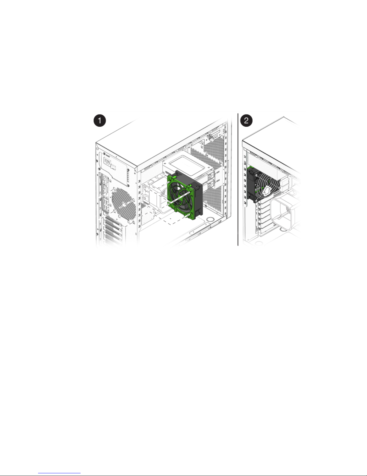
Chapter 5 Maintaining the Workstation 5-37
9. Locate the four corner holes in the chassis grill where the fan tabs will be
installed.
10. Gently press the fan against the chassis, with the four hooks on the back of the
fan bracket in the corner holes on the chassis grill.
11. Slide the fan up until the latches click into their locked position (see
FIGURE 5-24).
FIGURE 5-24 Installing the System Fan
12. Route the fan’s power cord through the cable management strap near the top right
corner of the motherboard.
13. Connect the fan cable to the SYS_FAN connector on the motherboard.
14. Close the system by performing the steps in Section 5.3.1, “Postinstallation
Instructions” on page 5-5.

5-38 Sun Ultra 20 M2 Workstation Service Manual • January 2007
5.13 Replacing the Power Supply
This section describes removing and installing the power supply.
5.13.1 Removing the Power Supply
Perform this procedure to remove the power supply.
1. Follow the steps in Section 5.2.2, “Powering Off the System and Removing the Left
Side Access Panel” on page 5-3.
2. Unplug the AC power cord from the system.
3. Gently lay the system on its right side on a stable, nonslip surface.
4. Locate the power supply (see
FIGURE 5-25).
FIGURE 5-25 Location of the Power Supply

Chapter 5 Maintaining the Workstation 5-39
5. Unfasten the connectors from the motherboard and release the cable management
straps (see
FIGURE 5-26).
6. Unfasten the power connectors attached to the motherboard, DVD drive, and
storage backplane (see
FIGURE 5-26 and TABLE 5-2).
FIGURE 5-26 Locations of Power Supply Connections on the Motherboard
7. Working from outside the back of the chassis, unfasten the four mounting screws.
TABLE 5-2 Power Supply Cable Connections
Power cable Connector Power cable Connector
P1 Motherboard PWR1 P3 DVD drive
P2 Motherboard PWR2 P4 Storage backplane

5-40 Sun Ultra 20 M2 Workstation Service Manual • January 2007
8. Remove the power supply from the interior of the system chassis (see FIGURE 5-27).
FIGURE 5-27 Removing the Power Supply From the Chassis
9. Install the new power supply as shown as Section 5.13.2, “Installing the Power
Supply” on page 5-41.

Chapter 5 Maintaining the Workstation 5-41
5.13.2 Installing the Power Supply
Perform this procedure to install the power supply.
1. Remove the new power supply from its package.
2. Locate where the power supply is to be installed, then place the power supply
inside the chassis (see
FIGURE 5-28).
a. Align the power supply IEC-320 connector (power cord socket) and fan with the
chassis back-panel opening.
b. Position the power supply with the chassis power supply brackets.
c. Rotate the power supply down and into the chassis.
FIGURE 5-28 Installing the Power Supply Into the Chassis
3. Fasten the four mounting screws on the back of the chassis to secure the power
supply to the chassis.
4. Reconnect the power supply cables (see
FIGURE 5-26 and TABLE 5-2), and then secure
them with the cable management straps.

5-42 Sun Ultra 20 M2 Workstation Service Manual • January 2007
Caution – When you connect the power supply cables, make sure that the cables do
not interfere with the DIMMs. If the cables push against the DIMMs, the DIMMs
might loosen from their connectors.
5. Verify that the four mounting screws are secure, that all cables are reconnected,
and that the cables are secured by the cable management straps.
6. Close the system by performing the steps in Section 5.3.1, “Postinstallation
Instructions” on page 5-5.
5.14 Replacing the I/O Board Assembly
The I/O board assembly sits beneath the DVD drive and contains the power switch,
power LED, and external connectors for the front panel.
5.14.1 Removing the I/O Board Assembly
Perform this procedure to remove the I/O board assembly.
1. Follow the steps in Section 5.2.2, “Powering Off the System and Removing the Left
Side Access Panel” on page 5-3.
2. Disconnect any audio, USB, and IEEE 1394 cables connected to the front of the
workstation.
3. Remove the front bezel (see Section 5.2.3, “Removing the Front Bezel” on page 5-4).
4. Locate the back of the I/O board assembly within the workstation.
5. Disconnect all cables on the back of the I/O board.

Chapter 5 Maintaining the Workstation 5-43
6. Loosen the captive screw securing the I/O board to the metal frame (see
FIGURE 5-29).
FIGURE 5-29 Removing the I/O Board Assembly
7. Push the I/O board out the front of the chassis.
8. Install the new I/O board assembly as shown in Section 5.14.2, “Installing the I/O
Board Assembly” on page 5-44.

5-44 Sun Ultra 20 M2 Workstation Service Manual • January 2007
5.14.2 Installing the I/O Board Assembly
Perform this procedure to install the I/O board assembly.
1. Follow the steps in Section 5.2.2, “Powering Off the System and Removing the Left
Side Access Panel” on page 5-3.
2. Place the system unit on a flat, stable surface.
3. Push the I/O board through the back of the metal I/O board frame until the front
panel is flush with the bezel opening (see
FIGURE 5-30). Wiggle side to side if the
board binds as you install it.
FIGURE 5-30 Installing the I/O Board Assembly
4. Tighten the captive screw on the metal I/O board frame to secure the I/O board.
5. Connect the internal USB, Power/LED, 1394, and audio cables to the back of the
I/O board.
The cables are color coded and keyed to ensure correct installation. See
FIGURE 1-4
and the service label on the chassis cover for the locations of the I/O board
connections.
6. Replace the front bezel.
7. Close the system by performing the steps in Section 5.3.1, “Postinstallation
Instructions” on page 5-5.
 Loading...