

Page 1

Sun™Ultra™2
UltraSPARC™-IIModuleX-Option
The Network Is the Computer
Sun Microsystems Computer Company
2550 Garcia Avenue
Mountain View, CA 94043 USA
415 960-1300 fax 415 969-9131
Part No.: 805-0937-10
Revision A, March 1997
™
Page 2

Copyright 1997 Sun Microsystems,Inc.2550GarciaAvenue,MountainView, California 94043-1100U.S.A.
All rights reserved.Thisproductordocumentisprotectedbycopyrightanddistributedunderlicensesrestrictingitsuse,copying,distribution,
and decompilation. No part of this productordocumentmaybereproducedinanyformbyanymeanswithoutpriorwrittenauthorizationof
Sun and its licensors, if any.
Portions of this productmaybederivedfromtheUNIX®system and fromtheBerkeley4.3BSDsystem,licensedfromtheUniversityof
California. UNIX is a registeredtrademarkintheUnitedStatesandinothercountriesandisexclusivelylicensedbyX/OpenCompanyLtd.
Third-partysoftware,includingfonttechnologyinthisproduct,isprotectedbycopyrightandlicensedfrom Sun’s suppliers.
RESTRICTEDRIGHTSLEGEND:Use,duplication,ordisclosurebythegovernmentis subject to restrictions as set forth in subparagraph(c)(1)(ii)
of the Rights in Technical Data and Computer Softwareclause at DFARS 252.227-7013 and FAR52.227-19.
Sun, Sun Microsystems,the Sun logo, Ultra, OpenBoot, and Solaris are trademarks or registered trademarks of Sun Microsystems, Inc. inthe
United States and in other countries. All SPARC trademarks areused under license and are trademarks or registered trademarks of SPARC
International, Inc. in the United States and in other countries. Productsbearing SPARCtrademarks are based upon an architecture developed by
Sun Microsystems,Inc.
The OPEN LOOK®and Sun™ Graphical User Interfaces weredeveloped by Sun Microsystems, Inc. for its users and licensees. Sun
acknowledges thepioneering efforts of Xerox Corporation in researchingand developing the concept of visual or graphical user interfaces for the
computer industry.Sun holds a nonexclusive license from Xerox to the Xerox Graphical User Interface, which license also covers Sun’s licensees
who implement OPEN LOOK GUIs and otherwise comply with Sun’s written license agreements.
X WindowSystem is a trademark of X Consortium, Inc.
THIS PUBLICATION IS PROVIDED “AS IS” WITHOUT WARRANTY OF ANY KIND, EITHER EXPRESS OR IMPLIED, INCLUDING,
BUT NOT LIMITED TO, THE IMPLIED WARRANTIES OF MERCHANTABILITY, FITNESS FOR A PARTICULAR PURPOSE, OR
NON-INFRINGEMENT.
Copyright 1997 Sun Microsystems,Inc., 2550 Garcia Avenue,Mountain View, Californie 94043-1100U.S.A.
Tous droitsréservés. Ce produit ou document est protégé par un copyright et distribué avec des licences qui en restreignentl’utilisation, la copie
et ladécompilation. Aucune partie de ce produit ou de sa documentation associée ne peut êtrereproduite sous aucune forme, par quelque moyen
que ce soit, sans l’autorisation préalable et écrite de Sun et de ses bailleurs de licence, s’ilyena.
Des parties de ce produitpourront être derivées du système UNIX®et du système Berkeley 4.3 BSD licencié par l’Université de Californie. UNIX
est unemarqueenregistrée aux Etats-Unis et dans d’autres pays, et licenciée exclusivement parX/Open Company Ltd. Le logiciel détenu par des
tiers, et qui comprendla technologie relative aux polices de caractères, est protégé par un copyright et licencié par des fournisseurs de Sun.
Sun, Sun Microsystems,le logo Sun, Ultra, OpenBoot, et Solaris sont des marques déposées ou enregistrées de Sun Microsystems, Inc. aux EtatsUnis etdansd’autres pays. Toutesles marques SPARC,utilisées sous licence, sont des marquesdéposées ou enregistrées de SPARCInternational,
Inc. aux Etats-Unis et dans d’autrespays. Les produits portant les marques SPARCsont basés sur une architecturedéveloppée par Sun
Microsystems,Inc.
Les utilisateurs d’interfaces graphiques OPEN LOOK®et Sun™ ont été développés de Sun Microsystems,Inc. pour ses utilisateurs et licenciés.
Sun reconnaîtles efforts de pionniers de Xerox Corporation pour la rechercheet le développement du concept des interfaces d’utilisation visuelle
ou graphique pour l’industrie de l’informatique. Sun détient une licence non exclusive de Xeroxsur l’interface d’utilisation graphique, cette
licence couvrant aussi les licenciés de Sun qui mettent en place les utilisateurs d’interfaces graphiques OPEN LOOK et qui en outre se
conforment aux licences écrites de Sun.
Le système X Windowest un produit du X Consortium, Inc.
CETTE PUBLICATION EST FOURNIE "EN L’ETAT" SANS GARANTIE D’AUCUNE SORTE, NI EXPRESSE NI IMPLICITE, Y COMPRIS, ET
SANS QUE CETTE LISTE NE SOIT LIMITATIVE, DES GARANTIES CONCERNANT LA VALEUR MARCHANDE, L’APTITUDE DES
PRODUITS A REPONDRE A UNE UTILISATIONPARTICULIERE OU LE FAITQU’ILS NE SOIENT PAS CONTREFAISANTS DE PRODUITS
DE TIERS.
Please
Recycle
Page 3

ElectromagneticCompatibility
FCC Class B Notice — United States
This device complies with Part 15 of the FCC Rules. Operation is subject to the following two
conditions:
1. This device may not cause harmful interference.
2. This device must accept any interference received, including interference that may cause
operation.
Note - This equipment has been tested and found to comply with the limits for a Class B
digital device, pursuant to Part 15 of the FCC Rules. These limits are designed to provide
reasonable protection against harmful interference in a residential installation. This
equipment generates, uses and can radiate radio frequency energy and, if not installed and
used in accordance with the instructions, may cause harmful interference to radio
communications. However, there is no guarantee that interference will not occur in a
particular installation. If this equipment does cause harmful interference to radio or
television reception, which can be determined by turning the equipment off and on, the user
is encouraged to try to correct the interference by one or more of the following measures:
• Reorient or relocate the receiving antenna.
• Increase the separation between the equipment and receiver.
• Connect the equipment into an outlet on a circuit different from that to
which the receiver is connected.
• Consult the dealer or an experienced radio/television technician for help.
iii
Page 4

Shielded Cables
Connections between the workstation and peripherals must be made using shielded cables in
order to maintain compliance with FCC radio frequency emission limits.
Modifications
Modifications to this device that are not approved by the party responsible for compliance
may void the authority granted to the user by the FCC to operate this equipment.
DOC Class B Notice — Canada
This digital apparatus does not exceed the Class B limits for radio noise emission for a digital
apparatus as set out in the Radio Interference Regulations of the Canadian Department of
Communications.
Avisconcernantles systèmes appartenantà la classe B du DOC — Canada
Le présent appareil numérique n’émet pas de bruits radioélectriques dépassant les limites
applicables aux appareils numériques de la classe B prescrites dans le Règlement sur le
brouillage radioélectriques édicté par le Ministère des Communications du Canada.
iv Sun Ultra 2 UltraSPARC-IIModule X-Option—March1997
Page 5

Nippon — Japan
ElectromagneticCompatibility v
Page 6

vi Sun Ultra 2 UltraSPARC-IIModule X-Option—March1997
Page 7

Contents
Electromagnetic Compatibility. . . . . . . . . . . . . . . . . . . . . . . . . . . iii
1. UltraSPARC-II Module X-Option. . . . . . . . . . . . . . . . . . . . . . . 1-1
1.1 System Software Requirements . . . . . . . . . . . . . . . . . . . . . 1-2
1.1.1 Solaris . . . . . . . . . . . . . . . . . . . . . . . . . . . . . . . . . . . . . . 1-2
1.1.2 Open Boot PROM . . . . . . . . . . . . . . . . . . . . . . . . . . . . 1-2
1.2 System Hardware Requirements . . . . . . . . . . . . . . . . . . . . 1-2
1.2.1 Determining Clock Frequency. . . . . . . . . . . . . . . . . . 1-2
1.3 SCD Compliance. . . . . . . . . . . . . . . . . . . . . . . . . . . . . . . . . . 1-2
1.4 UltraSPARC-II Module X-Option Kit. . . . . . . . . . . . . . . . . 1-3
1.5 Flash PROM Update Utility . . . . . . . . . . . . . . . . . . . . . . . . 1-3
1.6 Using This Book . . . . . . . . . . . . . . . . . . . . . . . . . . . . . . . . . . 1-3
2. Opening the System Unit . . . . . . . . . . . . . . . . . . . . . . . . . . . . . . 2-1
2.1 Removing Power from the System. . . . . . . . . . . . . . . . . . . 2-1
2.2 Removing the System Unit Cover . . . . . . . . . . . . . . . . . . . 2-3
2.3 Attaching the Wrist Strap . . . . . . . . . . . . . . . . . . . . . . . . . . 2-5
vii
Page 8

3. Updating the Flash PROM . . . . . . . . . . . . . . . . . . . . . . . . . . . . . 3-1
4. Removing the UltraSPARC Module . . . . . . . . . . . . . . . . . . . . . 4-1
5. Installing the UltraSPARC Module. . . . . . . . . . . . . . . . . . . . . . 5-1
6. Completing the Installation . . . . . . . . . . . . . . . . . . . . . . . . . . . . 6-1
6.1 Changing the Clocking Select Jumper. . . . . . . . . . . . . . . . 6-1
6.2 Closing the System Unit . . . . . . . . . . . . . . . . . . . . . . . . . . . 6-3
6.3 Turning On the Power . . . . . . . . . . . . . . . . . . . . . . . . . . . . . 6-5
6.4 Power-On Self-Test (POST) . . . . . . . . . . . . . . . . . . . . . . . . . 6-5
6.5 EnergyStar. . . . . . . . . . . . . . . . . . . . . . . . . . . . . . . . . . . . . . . 6-5
viii Sun Ultra 2 UltraSPARC-II Module X-Option—March 1997
Page 9

UltraSPARC-II ModuleX-Option
This book contains procedures for installing an UltraSPARC-II module
x-option in a SunUltra2 system.
1
Figure 1-1 Ultra 2 System
1-1
Page 10

1
1.1 System SoftwareRequirements
1.1.1 Solaris
Ultra 2 systems equipped with UltraSPARC-II module(s) require using
Solaris 2.5.1 or later system software releases.
1.1.2 Open Boot PROM
UltraSPARC-II systems require OpenBootPROM version 3.7 (or later).
1.2 System HardwareRequirements
Ultra 2 systems operated in multiprocessor mode must use processor modules
of the same clock frequency.
1.2.1 Determining Clock Frequency
To determine the clock frequency of the processor module(s) already installed
in your system:
♦ Query your system by typing:
% prtconf -vp | grep banner-name
banner-name: ‘Sun Ultra 2 UPA/SBus (2 X UltraSPARC 168Hz)’
The system responds with the quantity (for example, 2 X) and speed (168
MHz) of the UltraSPARC module(s) installed.
1.3 SCD Compliance
Sun Ultra 2 systems have been independently tested and verified to comply
with revision 2.1 of the SPARC Compliance Definition (SCD) developed by
SPARC International, Inc. These systems are binary compatible with all other
systems and software that conform to SCD version 2.1.
1-2 Sun Ultra 2 UltraSPARC-II Module X-Option—March1997
Page 11

1.4 UltraSPARC-II Module X-Option Kit
Each UltraSPARC-II module x-option kit contains:
• This book
• UltraSPARC-II module
• Antistatic wrist strap
1.5 Flash PROM Update Utility
If you do not have OpenBoot PROM version 3.7 (or later) installed in your
system and do not have the flash PROM update utility software containing
version 3.7 (or later), you must obtain the software from SunServiceor
another authorized service provider.
1.6 Using This Book
This book shows you how to install and test UltraSPARC-II modules in Ultra 2
systems. The procedures are arranged in a sequence of four chapters. Read
and perform the procedures in the remainder of this book in sequence, starting
with Chapter 2, “Opening the System Unit,” and ending with
Chapter 6.
1
UltraSPARC-II Module X-Option 1-3
Page 12

1
1-4 Sun Ultra 2 UltraSPARC-II Module X-Option—March1997
Page 13

OpeningtheSystemUnit
This chapter contains the following sections:
• Removing Power from the System
• Removing the System Unit Cover
• Attaching the Wrist Strap
2.1 Removing Power from the System
Before turning off system power, shut down the operating system to avoid loss
of data.
1. If your system is not a standalone, notify users that the system is going
down.
Refer to the Solaris Handbook for the procedure.
2. Back up the system files and data.
Refer to the Solaris Handbook for the procedure.
3. Shut down the system.
4. Turn the power off to the monitor and all peripherals connected to the
system.
2
5. Remove DC power from the system by pressing the Standby side of the
Note – After the Standby switch is pressed, it returns to its original position.
power switch on the back panel (Figure 2-1).
2-1
Page 14

2
Standby
Figure 2-1 Standby Switch
When the power is off, the LED on the middle front of the system is not lit and
the fans are not running (Figure 2-2).
LED
Figure 2-2 Front Panel LED Location
2-2 Sun Ultra 2 UltraSPARC-II Module X-Option—March1997
Page 15

Caution – When the Power On/Standby switch is pressed and the AC power
cord remains connected to a power outlet, hazardous AC voltage is still present
in the power supply primary.
6. Detach all cords and cables connected to the system unit except for the AC
power cord.
The AC power cord provides the grounding path for safely discharging
static electricity. Note where each cord and cable attaches to the system
unit.
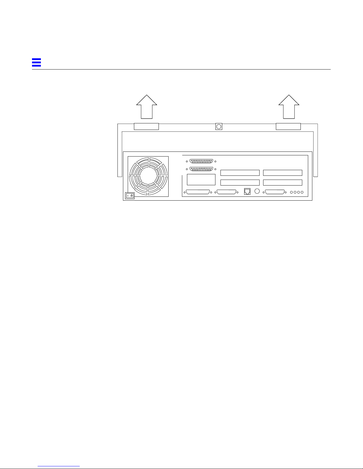
2.2 Removing the System UnitCover
2
Plastic tab Plastic tab
Figure 2-3 Opening the System Unit
1. Use a Phillips screwdriver to remove the lock block (if installed) on the
top cover and back panel (Figure 2-3).
2. Pull the two top cover plastic tabs towards yourself (Figure 2-3).
Lock block
Opening the System Unit 2-3
Page 16
2
Figure 2-4 Lifting the Top Cover
3. Lift the top cover so that it clears the chassis, and push the cover forward
so that it clears the chassis (Figure 2-4).
2-4 Sun Ultra 2 UltraSPARC-II Module X-Option—March1997
Page 17

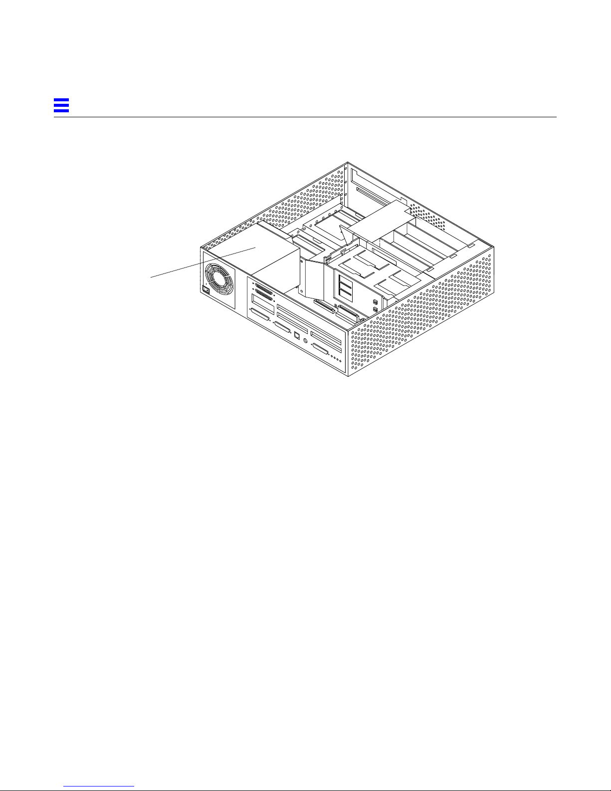
2.3 Attaching the Wrist Strap
Wrap the wrist strap twice around your
wrist (adhesive against your skin).
Figure 2-5 Attaching the Wrist Strap
2
Attach end to metal
casing of power supply
Opening the System Unit 2-5
Page 18
2
Power supply
Figure 2-6 Power Supply Location
1. Unwrap the first two folds of the wrist strap and wrap the adhesive side
firmly around your wrist (Figure 2-5).
2. Attach the adhesive copper strip to the metal casing of the power supply
inside your system (Figure 2-6).
2-6 Sun Ultra 2 UltraSPARC-II Module X-Option—March1997
Page 19

UpdatingtheFlashPROM
♦ Use the flash PROM update CD-ROM and the accompanying
programming guide to update your system flash PROM to OpenBoot
PROM version 3.7 (or later).
Note – If you do not have OpenBoot PROM version 3.7 (or later) installed in
your system and do not have the flash PROM update utility software
containing version 3.7 (or later), you must obtain the software from SunService
or another authorized service provider.
3
3-1
Page 20

3
3-2 Sun Ultra 2 UltraSPARC-II Module X-Option—March1997
Page 21

RemovingtheUltraSPARCModule
Read this chapter if:
• Your system is equipped with one UltraSPARC module and you are
replacing the module
• Your system is equipped with one UltraSPARC module and you are
replacing the module with two new modules
• Your system is equipped with two UltraSPARC modules and you are
replacing them with two new modules
Skip this chapter and read Chapter 5 if:
• Your system is equipped with one UltraSPARC-II module and you are
adding a second module of the same clock frequency
4
4-1
Page 22

4
Slot 0
Slot 1
Figure 4-1 UltraSPARC Module Locations and Shroud-Assembly Processor Area
4-2 Sun Ultra 2 UltraSPARC-II Module X-Option—March1997
Page 23

4
135-degrees
90-degrees
Figure 4-2 Removing the UltraSPARC Module
1. Grip the sides of the shroud-assembly processor area (Figure 4-1).
2. With the thumbs of both hands, simultaneously lift the two levers on the
90-degrees
module upwards and to the side (about 135-degrees) (Figure 4-2).
135-degrees
3. Lift the module upwards until it clears the system chassis.
4. Place the module on an antistatic surface.
Removing the UltraSPARCModule 4-3
Page 24

4
4-4 Sun Ultra 2 UltraSPARC-II Module X-Option—March1997
Page 25

Slot 0
Slot 1
InstallingtheUltraSPARCModule
Figure 5-1 Ultra 2 Processor Slot Locations
5
1. Unpack the processor module.
2. Place the module on an antistatic surface.
3. Identify the appropriate or available slot (Figure 5-1).
5-1
Page 26

5
• If your system is equipped with one UltraSPARC module, the module must
be installed in slot 0.
• If your system is equipped with two UltraSPARC modules, each slot will
have a module installed.
4. On the antistatic surface, hold the module in an upright position so that
the plastic surface faces you (Figure 5-2).
5. Move the levers on the module to the 135-degree position (Figure 5-2).
135-degrees
90-degrees
90-degrees
Figure 5-2 Lowering the Module Into the Chassis
6. Lower the module along the vertical plastic guides until the module
touches the slot socket on the main logic board (Figure 5-2).
135-degrees
5-2 Sun Ultra 2 UltraSPARC-II Module X-Option—March1997
Page 27

5
7. With both hands, simultaneously turn and press the levers downward to
the fully horizontal position. Firmly press the module downward into the
socket until it is fully seated and the levers are fully locked
(Figure 5-3).
Figure 5-3 Locking the Module in Place
Installing the UltraSPARCModule 5-3
Page 28

5
5-4 Sun Ultra 2 UltraSPARC-II Module X-Option—March1997
Page 29

CompletingtheInstallation
5.1 Changing the Clocking SelectJumper
• Table 6-1 gives information about the clocking select jumper functionality.
• Figure 6-1 shows the location of the clocking select jumper on the main logic
board.
• Figure 6-2 shows the two available jumper settings.
Table 5-1 UltraSPARC Module Clocking Select Jumper Settings
Jumper Pins1+2Select Pins2+3Select
5
Default Jumper on
Pins
J2301 300 MHz, 2 Mbytes
external cache
UltraSPARC-II
modules.
All 168 MHz and
200 MHz
UltraSPARC-I
modules.
2+3
5-1
Page 30

5
J3002
J2301
Back Panel
Main Logic Board (MLB)
Fan
Power
Supply
Fan
Left Panel
Fan
Fan
CPU — 0
CPU — 1
J2801
J2901
Speaker
Front Panel
Figure 5-1 Clocking Select Jumper Location on Main Logic Board
Right Panel
5-2 UltraSPARC-II Module X-Option—March1997
Page 31
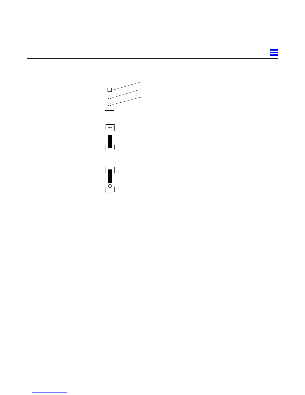
*
J2301
*
J2301
*
J2301
Pin 1
Pin 2
Pin 3
Default jumper position,
UltraSPARC-I modules,
168 MHz and 200 MHz
Jumper position,
UltraSPARC-II modules,
300 MHz
5
A
B
Figure 5-2 Clocking Select Jumper Positions
To change the jumper:
♦ Use needlenose pliers to remove the jumper from position A and to install
the jumper at position B (Figure 6-2).
5.2 Closing the System Unit
1. Remove the wrist strap from your wrist and then from the power supply.
2. Hold the cover at an angle to the system unit. Seat the cover lip to the
chassis lip.
3. Slowly lower the cover onto the system unit so that the rear of the cover
seats with the chassis back panel (Figure 6-3).
Completing the Installation 5-3
Page 32

5
Figure 5-3 Lowering the Cover Onto the System Unit Back Panel
4. Guide the two top cover plastic tabs in place onto the back panel.
You will hear a click as each tab seats with the back panel (Figure 6-4).
5. Use a Phillips screwdriver to reinstall the lock block to the back pane
(Figure 6-4).
Plastic tab
Figure 5-4 Cover Tabs and Lock Block
5-4 UltraSPARC-II Module X-Option—March1997
Lock block
Plastic tab
Page 33

5.3 Turning On the Power
1. Reattach all cords and cables connected to the system unit.
2. Turn on the power in this order:
• External SCSI peripheral with SCSI terminator attached
• External SCSI peripheral daisy-chained to the SCSI peripheral with the SCSI
terminator attached
• Monitor
• Power On/Standby switch on the system unit back panel (Figure 6-5).
The operating system should load or the ok prompt should appear on the
monitor.
5
Figure 5-5 Power On/Standby Switch
5.4 Power-On Self-Test (POST)
For a full description of the Power-On Self-Test (POST), refer to the Sun Ultra 2
Service Manual.
5.5 EnergyStar
If you experience RED State Exception failures when exercising EnergyStar
suspend/resume functions, install patch 104729-01.
An alternative is to install the Solaris 2.5.1 Hardware: 4/97 release which also
incorporates a correction to this problem.
Completing the Installation 5-5
Page 34

5
5-6 UltraSPARC-II Module X-Option—March1997
 Loading...