

Page 1
Sun Blade
TM
T6320 Server Module
Service Manual
Sun Microsystems, Inc.
www.sun.com
Part No. 820-2386-12
June 2009, Revision A
Submit comments about this document at: http://www.sun.com/hwdocs/feedback
Page 2

Copyright ©2009 Sun Microsystems, Inc., 4150Network Circle,Santa Clara, California 95054, U.S.A.All rights reserved.
Sun Microsystems,Inc. has intellectual property rights relating to technology embodiedin the product that is described inthis document. In
particular,and without limitation, these intellectualproperty rightsmay include one or more ofthe U.S. patents listed at
http://www.sun.com/patents and one or more additional patentsor pending patent applications in the U.S.and in other countries.
This distributionmay include materials developed bythird parties.
Parts ofthe product may be derivedfrom BerkeleyBSD systems, licensed from the University ofCalifornia. UNIX is a registered trademarkin
the U.S.and in other countries, exclusivelylicensed through X/Open Company, Ltd.
Sun, SunMicrosystems, the Sun logo, Java,Solaris and Sun Blade are trademarks orregistered trademarks of SunMicrosystems, Inc., and its
subsidiaries, inthe U.S. and other countries.
All SPARC trademarks are used under licenseand aretrademarks or registered trademarks of SPARC International,Inc. in the U.S. and other
countries. Productsbearing SPARC trademarks are based upon architecture developedby Sun Microsystems, Inc.
Products covered byand information contained in thisservice manual are controlled by U.S. ExportControl lawsand may be subject tothe
export orimport laws in other countries.Nuclear, missile, chemical biologicalweapons or nuclear maritime end uses orend users, whether
direct orindirect, arestrictly prohibited.Export or reexport to countries subject toU.S. embargoor to entities identified onU.S. export exclusion
lists, including,but not limited to, thedenied persons and specially designatednationals lists is strictly prohibited.
Use ofany spare or replacement CPUs is limitedto repairor one-for-one replacement of CPUs in products exportedin compliance with U.S.
export laws.Use of CPUs as productupgrades unless authorized by the U.S. Governmentis strictly prohibited.
DOCUMENTATION IS PROVIDED "AS IS" AND ALL EXPRESS OR IMPLIED CONDITIONS, REPRESENTATIONS AND WARRANTIES,
INCLUDING ANY IMPLIED WARRANTY OF MERCHANTABILITY, FITNESS FOR A PARTICULARPURPOSE OR NON-INFRINGEMENT,
ARE DISCLAIMED, EXCEPT TO THE EXTENT THAT SUCH DISCLAIMERS ARE HELD TO BE LEGALLY INVALID.
Copyright ©2009 Sun Microsystems, Inc., 4150Network Circle,Santa Clara, California 95054, Etats-Unis.Tousdroits réservés.
Sun Microsystems,Inc. détient les droits de propriété intellectuels relatifs àla technologie incorporée dans le produit quiest décrit dans ce
document. Enparticulier, et ce sanslimitation, ces droits de propriété intellectuelle peuvent inclure unou plus des brevets américains listés à
l’adresse http://www.sun.com/patentset un ou les brevets supplémentaires oules applications de brevet enattente auxEtats - Unis et dansles
autres pays.
Cette distributionpeut comprendredes composants développés par destierces parties.
Des partiesde ce produit pourront être dérivées des systèmes BerkeleyBSD licenciés par l’Université deCalifornie. UNIX est une marque
déposée auxEtats-Unis et dans d’autres payset licenciée exclusivement par X/Open Company, Ltd.
Sun, SunMicrosystems, le logo Sun, Java,Solaris et Sun Blade sont des marquesde fabrique ou des marques déposées deSun Microsystems,
Inc., etses filiales, aux Etats-Unis etdans d’autres pays.
Toutes les marques SPARC sont utilisées souslicence et sont des marques defabrique ou des marques déposées de SPARCInternational, Inc.
aux Etats-Uniset dans d’autres pays. Lesproduits portantles marquesSPARCsont basés sur une architecture développéepar Sun
Microsystems, Inc.
Ce produitest soumis à la législationaméricaine en matière de contrôle des exportationset peut être soumis à la règlementationen vigueur
dans d’autrespays dans le domaine desexportations et importations. Les utilisations , ouutilisateurs finaux, pour des armesnucléaires, des
missiles, desarmes biologiques et chimiques oudu nucléaire maritime, directement ou indirectement, sont strictement interdites. Les
exportations oureexportations vers les pays sousembargo américain,ou vers des entités figurantsur les listes d’exclusion d’exportation
américaines, ycompris, mais de manière nonexhaustive, la liste de personnes qui fontobjet d’un ordre de ne pas participer, d’une façon directe
ou indirecte,aux exportations des produits ou des servicesqui sont régis par lalégislation américaine en matière de contrôle desexportations et
la listede ressortissants spécifiquement désignés, sontrigoureusement interdites. L’utilisation de pièces détachéesou d’unités centrales de
remplacement estlimitée aux réparations ou àl’échange standardd’unités centrales pour les produits exportés,conformément à la législation
américaine enmatière d’exportation. Sauf autorisation par les autoritésdes Etats-Unis, l’utilisation d’unités centralespour procéderà des mises
à jourde produits est rigoureusement interdite.
LA DOCUMENTATION EST FOURNIE "EN L’ETAT" ET TOUTES AUTRES CONDITIONS, DECLARATIONS ET GARANTIES EXPRESSES
OU TACITES SONT FORMELLEMENT EXCLUES,DANS LA MESURE AUTORISEE PAR LA LOI APPLICABLE, Y COMPRISNOTAMMENT
TOUTE GARANTIE IMPLICITE RELATIVE A LA QUALITE MARCHANDE, A L’APTITUDE A UNE UTILISATION PARTICULIERE OU A
L’ABSENCE DE CONTREFACON.
Page 3

Contents
Preface ix
1. Sun Blade T6320 Server Module Product Description 1–1
1.1 Component Overview 1–1
1.1.1 Multicore Processor Information 1–9
1.2 Support for RAID Storage Configurations 1–10
1.2.1 Sun Blade RAID 5 Expansion Module 1–11
1.2.2 Sun Blade RAID 0/1 G2 Expansion Module 1–11
1.3 Finding the Serial Number 1–11
1.4 Additional Service Related Information 1–14
2. Sun Blade T6320 Server Module Diagnostics 2–1
2.1 Sun Blade T6320 Server Module Diagnostics Overview 2–2
2.2 Memory Configuration and Fault Handling 2–7
2.2.1 FB-DIMM Configuration Guidelines 2–7
2.2.1.1 DIMM Installation Rules 2–8
2.2.1.2 Memory Fault Handling 2–11
2.2.1.3 Troubleshooting Memory Faults 2–11
2.3 Interpreting System LEDs 2–12
2.3.1 Front Panel LEDs and Buttons 2–12
iii
Page 4

2.3.2 Ethernet Port LEDs 2–16
2.4 Using ILOM for Diagnosis and Repair Verification 2–16
2.5 Using the ILOM Web Interface For Diagnostics 2–18
2.5.1 Changing POST Settings With the ILOM Web Interface 2–19
2.5.2 Changing POST Settings With the ILOM CLI 2–21
2.5.3 Displaying System Faults 2–21
2.5.3.1 Viewing Fault Status Using the ILOM Web Interface 2–
22
2.5.3.2 Viewing Fault Status Using the ILOM CLI 2–23
2.5.4 Displaying the Environmental Status with the ILOM CLI 2–24
2.5.5 Displaying the Environmental Status and Sensor Readings with the
ILOM Web Interface 2–25
2.5.6 Displaying FRU Information 2–27
2.5.6.1 Using the ILOM Web Interface to Display FRU
Information 2–27
2.5.6.2 Using the CLI to Display FRU Information 2–28
2.6 Running POST 2–31
2.6.1 Controlling How POST Runs 2–31
2.6.2 Changing POST Parameters 2–34
2.6.2.1 Using the Web Interface to Change POST Parameters
2–34
2.6.2.2 Using the CLI to Change POST Parameters 2–37
2.6.3 Interpreting POST Messages 2–38
2.6.4 Clearing POST Detected Faults 2–39
2.6.4.1 Clearing Faults With the Web Interface 2–40
2.6.4.2 Clearing Faults With the ILOM CLI 2–41
2.6.4.3 Clearing Faults Manually with ILOM 2–42
2.6.4.4 Clearing Hard Drive Faults 2–42
2.7 Using the Solaris Predictive Self-Healing Feature 2–42
iv Sun Blade T6320 Server Module Service Manual • June 2009
Page 5

2.7.1 Identifying Faults With the fmadm faulty and fmdump
Commands 2–43
2.7.1.1 Using the fmadm faulty Command 2–43
2.7.1.2 Using the fmdump Command 2–44
2.7.2 Clearing PSH Detected Faults 2–45
2.7.3 Clearing the PSH Fault From the ILOM Logs 2–46
2.8 Collecting Information From Solaris OS Files and Commands 2–47
2.8.1 Checking the Message Buffer 2–47
2.8.2 Viewing the System Message Log Files 2–48
2.9 Managing Components With Automatic System Recovery Commands 2–
48
2.9.1 Displaying System Components With the show /SYS Command
2–50
2.10 Exercising the System With SunVTS 2–51
2.10.1 Checking SunVTS Software Installation 2–51
2.10.2 Exercising the System Using SunVTS Software 2–52
2.10.3 Steps for Exercising the System With SunVTS Software 2–52
2.11 Resetting the Password to the Factory Default 2–56
2.11.1 To Reset the Root Password to the Factory Default 2–56
3. Replacing Hot-Swappable and Hot-Pluggable Components 3–1
3.1 Hot-Pluggable Hard Drives 3–1
3.2 Hot-Plugging a Hard Drive 3–1
3.2.1 Rules for Hot-Plugging 3–2
3.2.2 Removing a Hard Drive 3–2
3.2.3 Replacing a Hard Drive or Installing a New Hard Drive 3–4
3.3 Adding PCI ExpressModules 3–5
4. Replacing Cold-Swappable Components 4–1
4.1 Safety Information 4–1
Contents v
Page 6

4.1.1 Safety Symbols 4–2
4.1.2 Electrostatic Discharge Safety 4–2
4.1.2.1 Using an Antistatic Wrist Strap 4–2
4.1.2.2 Using an Antistatic Mat 4–3
4.2 Common Procedures for Parts Replacement 4–3
4.2.1 Required Tools 4–3
4.2.2 Shutting Down the System 4–3
4.2.3 Using the ILOM Web Interface to Shut Down the Server Module
4–4
4.2.4 Using the ILOM CLI to Shut Down the Server Module 4–5
4.3 Removing and Replacing DIMMs 4–10
4.3.1 Removing the DIMMs 4–10
4.3.2 Replacing the DIMMs 4–14
4.3.2.1 Verifying DIMM Installation 4–15
4.4 Removing and Replacing the Service Processor 4–15
4.4.1 Removing the Service Processor 4–15
4.4.2 Replacing the Service Processor 4–17
4.5 Removing and Replacing the Battery on the Service Processor 4–18
4.5.1 Replacing the Battery on the Service Processor 4–19
4.6 Replacing or Installing the Sun Blade RAID 5 Expansion Module 4–20
4.6.1 Installing the RAID 5 Expansion Module 4–21
4.6.2 Configuring the RAID 5 Expansion Module 4–24
4.6.3 Creating a Bootable Array With the RAID 5 Expansion Module 4–
25
4.6.4 Additional Information 4–25
4.7 Removing and Replacing the Sun Blade G2 RAID 0/1 Expansion Module
4–25
4.7.1 Replacing the RAID 0/1 Expansion Module 4–26
4.7.2 Verifying the RAID 0/1 Expansion Module Installation 4–27
4.8 Finishing Component Replacement 4–28
vi Sun Blade T6320 Server Module Service Manual • June 2009
Page 7

4.8.1 Replacing the Cover 4–28
4.8.2 Reinstalling the Server Module in the Chassis 4–28
A. Specifications A–1
A.1 Physical Specifications A–1
A.1.1 System Environmental Specifications A–2
A.2 Motherboard Block Diagram A–3
B. Creating a Bootable Array With the Sun Blade RAID 5 Expansion Module B–1
B.1 About Creating a Bootable Array on a SPARC System B–2
B.2 Creating a Bootable Array Task Map B–2
B.3 Modifying the Miniroot Directory On the Install Server B–3
B.4 Modifying the Product Installation Directory on the Install Server B–5
B.5 Building a Logical Drive On Which to Install the Solaris OS B–6
B.6 Next Steps B–11
B.6.1 Additional Information B–12
C. Installing the Solaris OS and the RAID 5 Expansion Module Driver C–1
C.1 Preparing to Install the Solaris OS C–1
C.2 Installing the RAID 5 Expansion Module Driver With the Solaris OS C–2
C.3 Next Steps C–4
C.3.1 Additional Information C–4
D. XVR-50 Graphics Accelerator D–1
D.1 Features D–1
D.2 Video Formats D–2
D.3 Sun OpenGL for Solaris Software D–3
D.4 Man Pages D–3
D.5 Optional Video Output D–4
D.6 Default Color Depth D–4
Contents vii
Page 8

D.7 Checking Device Configuration D–5
D.8 HD15 Video Output Port D–6
Index Index–1
viii Sun Blade T6320 Server Module Service Manual • June 2009
Page 9

Preface
The Sun BladeTMT6320 Server Module Service Manual provides information to aid in
diagnosing hardware problems and describes how to replace components. This
manual also describes how to add components such as hard drives and memory.
This manual is written for technicians, service personnel, and system administrators
who service and repair computer systems. The person qualified to use this manual:
■ Can open a system chassis, and can identify and replace internal components.
■ Understands the Solaris™ Operating System and the command-line interface.
■ Has superuser privileges for the system being serviced.
■ Understands typical hardware troubleshooting tasks.
Using UNIX Commands
This document might not contain information about basic UNIX®commands and
procedures such as shutting down the system, booting the system, and configuring
devices. Refer to the following for this information:
■ Software documentation that you received with your system
■ Solaris Operating System documentation, which is at:
http://docs.sun.com
ix
Page 10

Typographic Conventions
*
Typeface
AaBbCc123 The names of commands, files,
AaBbCc123
AaBbCc123 Book titles, new words or terms,
* The settings on your browser might differ from these settings.
Meaning Examples
Edit your.login file.
and directories; on-screen
computer output
What you type, when contrasted
with on-screen computer output
words to be emphasized.
Replace command-line variables
with real names or values.
Type ls -a to list all files.
% You have mail.
% su
Password:
Read Chapter 6 in the User’s Guide.
These are called class options.
Yo u must be superuser to do this.
To delete a file, type rm filename.
Shell Prompts
Shell Prompt
C shell machine-name%
C shell superuser machine-name#
Bourne shell and Korn shell $
Bourne shell and Korn shell superuser #
Accessing Sun Documentation
You can view, print, or purchase a broad selection of Sun documentation, including
localized versions, at:
http://docs.sun.com/app/docs/prod/blade.t6320
To find other product documents, search on the software name or book title.
x Sun Blade T6320 Server Module Service Manual • June 2009
Page 11

Document Title Description
Sun Blade T6320 Server Module Product Notes,
820-2383
Sun Blade T6320 Server Module Installation
Guide, 820-2384
Sun Integrated Lights Out Manager 2.0
Supplement for Sun Blade T6320 Server
Modules, 820-2546
Sun Blade T6320 Server Module Safety and
Compliance Manual, 820-2387
Chassis Documentation (Refer to the documents for your specific modular system chassis.)
Integrated Lights Out Manager ILOM
Administration Guide
Modular System Product Notes Late-breaking information about the chassis and related
Modular System Service Manual Component removal and replacement procedures, diagnostics
Software Documentation
Sun Integrated Lights out Manager 2.0 User’s
Guide, 820-1188
Configuring Jumpstart Servers to Provision Sun
x86-64 Systems, 819-1962-10
Solaris 10 8/07 Installation Guide: NetworkBased Installations
Sun VTS 6.4 User’s Guide, 820-1669 Testing the server module, and creating custom hardware tests.
Beginner’s Guide to LDoms: Understanding and
Deploying Logical Domains, 820-0832
Solaris Operating System documentation All information related to Solaris system administration
Important late-breaking information about the server module
and related software.
Basic information about installing, powering on and installing
software. If you purchased hard drives with preinstalled
software you can also find information here:
http://www.sun.com/software/preinstall
ILOM information specific to the UltraSPARC and the Sun Blade
T6320 server module. Provides command comparisons of the
ALOM CMT and ILOM CLI command sets.
Important safety information for the
module
ILOM information specific to the modular system chassis.
software.
information and specifications.
Advanced Lights Out Manager (ALOM) CMT software.
Configuring JumpStart servers.
Setting up network-based installations and JumpStart servers.
Learning about LDoms principles.
commands and features. Go to http://www.docs.sun.com
.
Sun Blade T6320 server
Preface xi
Page 12

Third-Party Web Sites
Sun is not responsible for the availability of third-party web sites mentioned in this
document. Sun does not endorse and is not responsible or liable for any content,
advertising, products, or other materials that are available on or through such sites
or resources. Sun will not be responsible or liable for any actual or alleged damage
or loss caused by or in connection with the use of or reliance on any such content,
goods, or services that are available on or through such sites or resources.
Documentation, Support, and Training
Sun Function URL
Documentation http://docs.sun.com/app/docs/prod/blade.t6320
Support http://www.sun.com/support/
Training http://www.sun.com/training/
Preinstalled Software http://www.sun.com/software/preinstall/
Sun Welcomes Your Comments
Sun is interested in improving its documentation and welcomes your comments and
suggestions. You can submit your comments by going to:
http://www.sun.com/hwdocs/feedback/
Please include the title and part number of your document with your feedback:
Sun Blade T6320 Server Module Service Manual, part number 820-2386.
xii Sun Blade T6320 Server Module Service Manual • June 2009
Page 13

CHAPTER
1
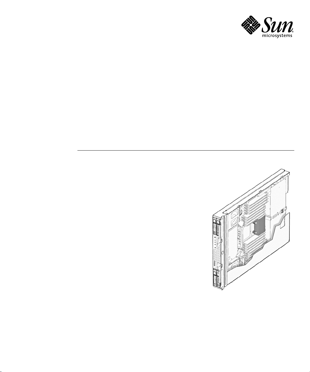
Sun Blade T6320 Server Module Product Description
This chapter provides an overview of the features of the Sun BladeTMT6320 server
module. (A server module is also known as a “blade.”)
The following topics are covered:
■ Section 1.1, “Component Overview” on page 1-1
■ Section 1.2, “Support for RAID Storage Configurations” on page 1-10
■ Section 1.3, “Finding the Serial Number” on page 1-11
■ Section 1.4, “Additional Service Related Information” on page 1-14
1.1 Component Overview
FIGURE 1-1, FIGURE 1-2 and FIGURE 1-3 show the main Sun Blade T6320 components
and some basic connections to the chassis. For information about connectivity to
system fans, PCI ExpressModules, Ethernet modules, and other components, see the
chassis documentation at:
http://docs.sun.com/app/docs/prod/blade.t6320
1-1
Page 14
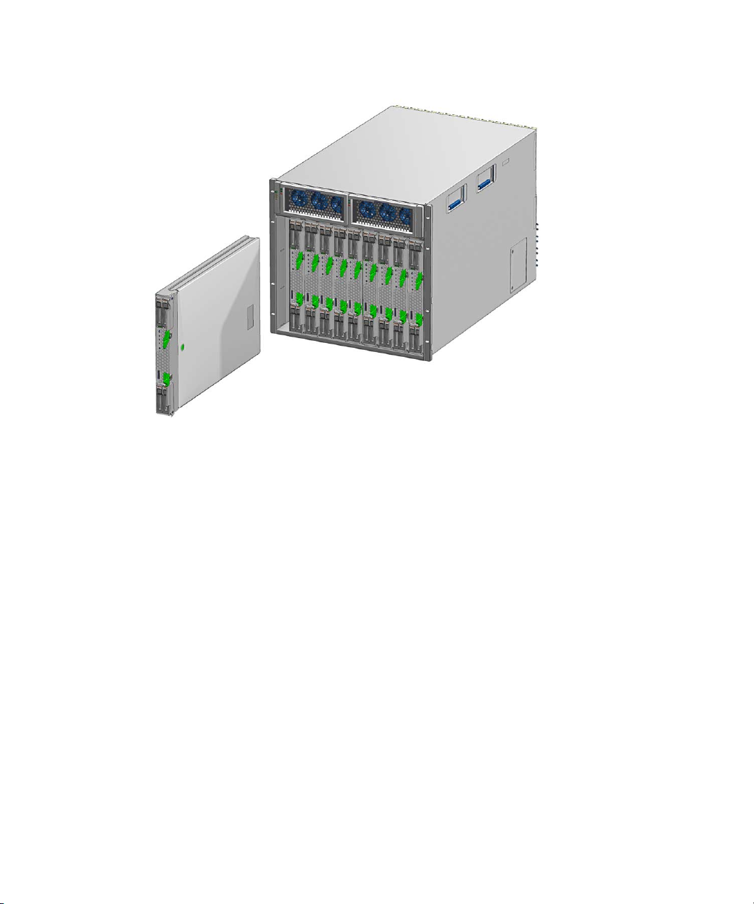
FIGURE 1-1 Sun Blade T6320 Server Module With Chassis
TABLE 1-1 lists the Sun Blade T6320 server module features. TABLE 1-2 lists some of
chassis input-output features.
1-2 Sun Blade T6320 Server Module Service Manual • June 2009
Page 15
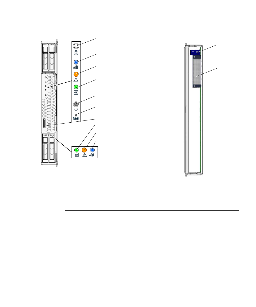
FIGURE 1-2 Front and Rear Panels
Front View
White - Locator LED
(press to reset the LED)
Blue - Ready to Remove LED
Amber - Service Action Required LED
Green - OK LED
Power button
NMI (non-maskable interrupt, for
service use only)
Universal Connector Port (UCP)
Green - Drive OK LED
Amber - Drive Service Action Required LED
Blue - Drive Ready to Remove LED
Rear View
Power
connector
Signal
connector
Note – For information about connecting to the server module refer to the Sun Blade
T6320 Server Module Installation Guide, 820-2384.
Chapter 1 Sun Blade T6320 Server Module Product Description 1-3
Page 16
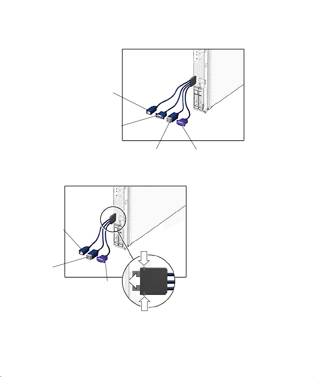
FIGURE 1-3 Cable Dongle Connectors
RJ-45 (Do not use this connector with
the Sun Blade T6320 Server Module)
DB-9 serial, male
(TTYA)
Four connector dongle cable (UCP-4)
RJ-45 serial
USB 2.0
(two connectors)
USB 2.0
(two connectors)
Three connector dongle cable (UCP-3)
VGA 15-pin, female
VGA 15-pin, female
Insert the connector straight into the server module.
1-4 Sun Blade T6320 Server Module Service Manual • June 2009
Page 17

Caution – Insert the connector straight into the server module. The cable dongle is
for temporary connections only. The cable dongle has not been evaluated for
electromagnetic compatibility (EMC). The cable dongle or server module connectors
could be damaged by closing rack doors or other impacts. Remove the cable dongle
during normal system operation.
Note – If you are using the older 4-cable dongle (UCP-4), do not use the RJ-45
connector with the Sun Blade T6320 server module. Use the DB-9 connector for serial
connections.
TABLE 1-1 Sun Blade T6320 Server Module Features
Feature Description
Processor One UltraSPARC®T2 multicore processor with 4MB L2 cache. Can execute up to 64
threads.
Memory 16 slots for fully buffered DIMMs (FB-DIMM), 667 MHz:
• 1 Gbyte (16 Gbyte maximum)
• 2 Gbyte (32 Gbyte maximum)
• 4 Gbyte (64 Gbyte maximum)
Internal hard drives Up to four hot-pluggable 2.5-inch hard drives.
• SFF SAS 73 Gbyte, 15k rpm, and 10k rpm
• SFF SAS 146 Gbyte, 10k rpm
(Filler panels are inserted anywhere hard drives are not installed.)
RAID Expansion
Modules
RAID expansion modules (hard drive management) with RAID 0, 1 controller.
Eight links, x2 SAS (3 Gb/s) or SATA (1.5 Gb/s), supporting four internal hard drives
and four x2 links to midplane. See Section 1.2, “Support for RAID Storage
Configurations” on page 1-10.
Chapter 1 Sun Blade T6320 Server Module Product Description 1-5
Page 18

TABLE 1-1 Sun Blade T6320 Server Module Features (Continued)
Feature Description
Universal
Connector Port
One universal connector port (UCP) in the front panel. A universal cable is included with
the chassis and can be purchased separately (
FIGURE 1-3). The following connections are
supported:
• USB 2.0*
• VGA video
• Serial (
FIGURE 1-3).
• Local keyboard, video, mouse, storage support (KVMS)
®
Architecture SPARC
V9 architecture, ECC protected
Platform group: sun4v
Platform name: SUNW, Sun Blade T6320 Server Module
Minimum system firmware 7.0.6 or subsequent compatible release
Solaris 10 8/07 OS with appropriate patches
XVR-50 on-board
graphics accelerator
• 2D 24-bit color graphics
• Flexible 8- and 24-bit color application support
• HD15 monitor connector for a wide range of Sun monitors
®
• 3D support through Sun OpenGL
Some USB connectors are thick andmay distort ordamage the connectorwhen you tryto connect twoUSB cables. You can use a USB hub
to avoid this problem.
TABLE 1-2 Interfaces With the chassis
Feature Description
for SolarisTMsoftware
Ethernet ports Two 10 Gb ethernet ports. Consult the chassis documentation or Network Express
Module (NEM) documentation for ethernet pass-through specifications. (See
FIGURE 1-5
and FIGURE A-2.)
PCI Express I/O Two 8-lane ports connect to chassis midplane. Can support up to two 8-lane PCI
ExpressModules (PCI EM). (
FIGURE 1-5)
SAS/SATA Four channels for remote storage connect from the RAID Express Module (REM) to the
chassis midplane.
Remote
Management
ILOM management controller on the service processor. CLI management (ssh only) and
N1 system manager support. DMTF CLI and ALOM-CMT compatible CLI available
through ssh. Remote console (remote KVMS) is configurable through OpenBoot PROM
and ILOM.
Remote
management
ILOM management controller on the service processor. CLI management (telnet, ssh) and
N1 system manager support. ALOM CMT shell within the ILOM controller.
Power Power is provided in the chassis
Cooling Environmental controls are provided by the chassis.
1-6 Sun Blade T6320 Server Module Service Manual • June 2009
Page 19
For more information about chassis features and controls, refer to the service manual
for your blade chassis at:
http://docs.sun.com/app/docs/prod/blade.srvr
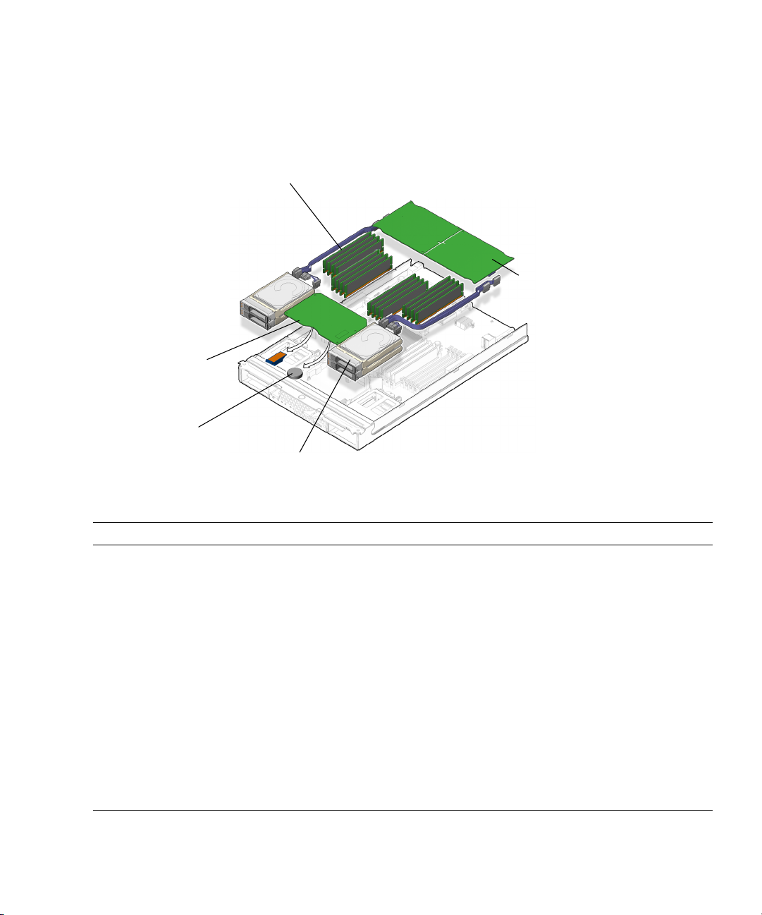
FIGURE 1-4 Field-Replaceable Units
FB-DIMMs
Service processor
with NVRAM (EEPROM)
with ILOM and ALOM
Battery
Hard drives
RAID Expansion Module
TABLE 1-3 Sun Blade T6320 Server Module FRU List
FRU Description FRU Name
Service
processor
card
Controls the host power and monitors host
system events (power and environmental).
Socketed EEPROM stores system configuration,
SYS/SP Section 4.4, “Removing and
all Ethernet MAC addresses, and the host ID.
Service
Lithium battery SYS/SP/BAT Section 4.5, “Removing and
processor
battery
REMs RAID expansion modules (Hard drive
SYS/MB/REM Section 4.6, “Replacing or
management for up to 12 hard drives)
Chapter 1 Sun Blade T6320 Server Module Product Description 1-7
*
Replacement Instructions
Replacing the Service
Processor” on page 4-15
Replacing the Battery on
the Service Processor” on
page 4-18
Installing the Sun Blade
RAID 5 Expansion Module”
on page 4-20
Section 4.6, “Replacing or
Installing the Sun Blade
RAID 5 Expansion Module”
on page 4-20
Page 20

TABLE 1-3
Sun Blade T6320 Server Module FRU List (Continued)
FRU Description FRU Name
*
FB-DIMMs 1 Gbyte, 2 Gbyte, 4 Gbyte SYS/MB/CMPx/B
Rx/CHx/Dx
Hard drive SFF SAS, or SATA 2.5-inch hard drive in NEMO
HDD0,1,2,3 Section 3.2.2, “Removing a
bracket
Server
Enclosure with CPU, motherboard SYS/MB New server module
Module
* The FRU name is used in system messages.
Replacement Instructions
Section 4.3.1, “Removing
the DIMMs” on page 4-10
Hard Drive” on page 3-2
1-8 Sun Blade T6320 Server Module Service Manual • June 2009
Page 21
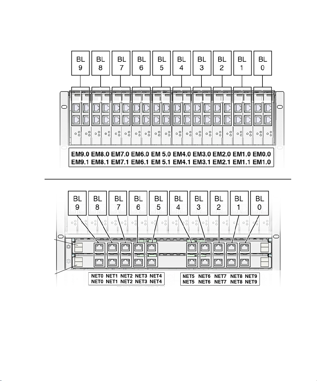
FIGURE 1-5 PCI Express and Ethernet Connections on a Sun Blade 6000 Modular System
BL = blade (server module)
NEM1
NEM0
1.1.1 Multicore Processor Information
The UltraSPARC®T2 multicore processor is the basis of the Sun Blade T6320 server
module. The processor has four, six, or eight UltraSPARC cores. Each core equates to
a 64-bit execution pipeline capable of running eight threads. The result is that the
Chapter 1 Sun Blade T6320 Server Module Product Description 1-9
Page 22

8-core processor handles up to 64 active threads concurrently. For more information
about the UltraSPARC
http://www.sun.com/processors/UltraSPARC-T2/features.xml
http://www.sun.com/servers/wp.jsp?tab=1
®
T2 multicore processor, go to:
1.2 Support for RAID Storage Configurations
In addition to software RAID configurations, you can set up hardware RAID 1
(mirroring) and hardware RAID 0 (striping) configurations for any pair of internal
hard drives using the on-board controller, providing a high-performance solution for
hard drive mirroring.
By attaching one or more external storage devices (such as the Sun Blade 6000 Disk
Module) to the Sun Blade T6320 server module, you can use a RAID to configure
system drive storage in a variety of different RAID levels.
As shipped, the internal hard drives are not configured for RAID. To make a disk
part of a RAID array while preserving the data on the drive, add the drive to a
mirrored RAID set (also known as hardware RAID Level 1).
Before configuring RAID, you must configure a RAID expansion module (REM).The
Sun Blade T6340 Server Module supports two REMs, the Sun Blade RAID 5 and Sun
Blade RAID 0/1 G2 Expansion Modules.
Refer to the following for RAID configuration instructions:
■ Uniform Command-Line Interface User's Guide, 820-2145
■ Sun StorageTek RAID Manager Software User's Guide, 820-1177
■ Sun StorageTek SAS RAID HBA Installation Guide Eight-Port, Internal HBA
http://docs.sun.com/app/docs/doc/820-1847-17
■ Sun Blade 6000 Disk Module Administration Guide, 820-4922
http://docs.sun.com/app/docs/prod/blade.6000disk~blade6000dskmod
Note – The Sun Blade 6000 Disk Module is an external storage blade that provides
eight additional drives for configuring RAID and is supported for both REMs.
1-10 Sun Blade T6320 Server Module Service Manual • June 2009
Page 23

1.2.1 Sun Blade RAID 5 Expansion Module
The Sun Blade RAID 5 Expansion Module supports RAID levels 0, 1, 1E, 10, 5, or 6
with global or dedicated hot spares. When a Sun Blade RAID 5 Expansion Module is
installed, SAS drives can be installed in disk slots 0 through 3. You can configure
these disks as RAID 0, 1, 5, or 10.
For information on creating a bootable array, see Appendix B. For information on
installing the OS on a bootable array, see Appendix C.
1.2.2 Sun Blade RAID 0/1 G2 Expansion Module
The Sun Blade RAID 0/1 G2 Expansion Module supports RAID 1 (two mirrored
disks with an optional hot spare) or RAID 1E (three or more mirrored disks with one
or two hot spares).
1.3 Finding the Serial Number
To obtain support for your system, you need the serial number. The serial number is
located on a sticker on the front of the server module (
FIGURE 1-6).
Chapter 1 Sun Blade T6320 Server Module Product Description 1-11
Page 24
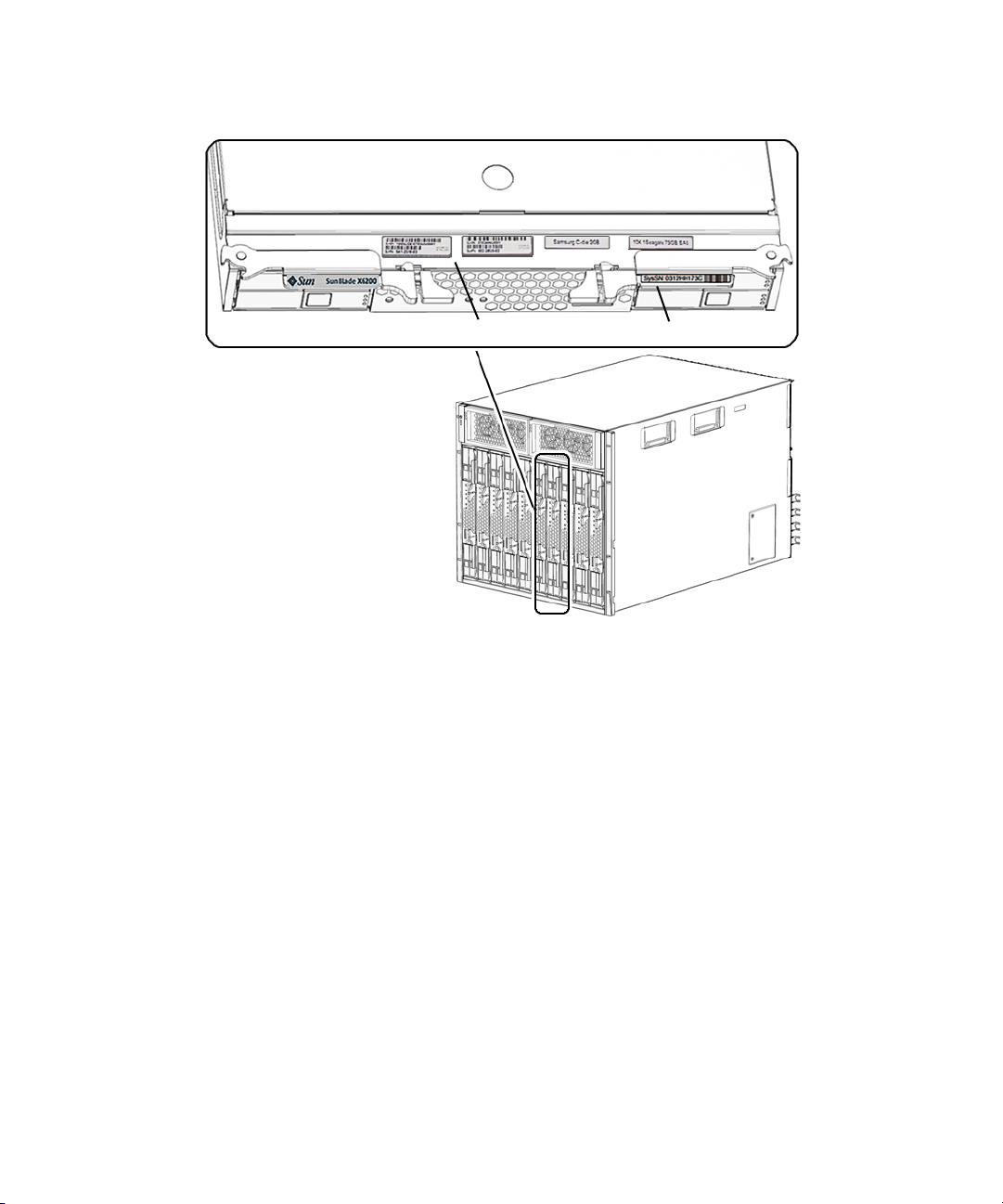
FIGURE 1-6 Serial Number and MAC Address Location
MAC address
Serial number
You can type the ILOM show /SYS command or the ALOM CMT showplatform
command to obtain the chassis serial number. Both examples are shown below.
1-12 Sun Blade T6320 Server Module Service Manual • June 2009
Page 25

-> show /SYS
/SYS
Targets:
SERVICE
LOCATE
ACT
OK2RM
SP
MB
MIDPLANE
HDD0
HDD1
HDD2
HDD3
NEM0
NEM1
FM0... .... .... ...
Properties:
type = Host System
keyswitch_state = Normal
chassis_name = SUN BLADE 6000 MODULAR SYSTEM
chassis_part_number = 123-4567-89
chassis_serial_number = 0000000-0000YB005A
chassis_manufacturer = SUN MICROSYSTEMS
product_name = Sun Blade T6320 Server Module
product_part_number = 541-2517-04
product_serial_number = 1005LCB-07385R001H
product_manufacturer = SUN MICROSYSTEMS
fault_state = OK
clear_fault_action = (none)
prepare_to_remove_status = NotReady
prepare_to_remove_action = (none)
return_to_service_action = (none)
power_state = On
ALOM CMT example:
Chapter 1 Sun Blade T6320 Server Module Product Description 1-13
Page 26
sc> showplatform
SUNW, Sun Blade T6320 Server Module
Blade Serial Number: 1005LCB-07385N005L
Chassis Serial Number: 1005LCB-0709YM007M
Slot Number: 5
Domain Status
------ -----S0 Running
sc>
1.4 Additional Service Related Information
Documentation for the Sun Blade T6320 server module, and related hardware and
software is listed in “Accessing Sun Documentation” on page x.
The following resources are also available.
■ SunSolve
the level of your service contract, you have access to Sun patches, the Sun System
Handbook, the SunSolve knowledge base, the Sun Support Forum, and additional
documents, bulletins, and related links. Access this site at:
http://www.sunsolve.sun.com/handbook_pub/
■ Predictive Self-Healing Knowledge Database – You can access the knowledge
article corresponding to a self-healing message by taking the Sun Message
Identifier (SUNW-MSG-ID) and typing it into the field on this page:
http://www.sun.com/msg/
sm
Online – Provides a collection of support resources. Depending on
1-14 Sun Blade T6320 Server Module Service Manual • June 2009
Page 27

CHAPTER
2
Sun Blade T6320 Server Module Diagnostics
This chapter describes the diagnostics that are available for monitoring and
troubleshooting the Sun Blade T6320 server module.
This chapter is intended for technicians, service personnel, and system
administrators who service and repair computer systems.
The following topics are covered:
■ Section 2.1, “Sun Blade T6320 Server Module Diagnostics Overview” on page 2-2
■ Section 2.2, “Memory Configuration and Fault Handling” on page 2-7
■ Section 2.3, “Interpreting System LEDs” on page 2-12
■ Section 2.4, “Using ILOM for Diagnosis and Repair Verification” on page 2-16
■ Section 2.5, “Using the ILOM Web Interface For Diagnostics” on page 2-18
■ Section 2.6, “Running POST” on page 2-31
■ Section 2.7, “Using the Solaris Predictive Self-Healing Feature” on page 2-42
■ Section 2.8, “Collecting Information From Solaris OS Files and Commands” on
page 2-47
■ Section 2.9, “Managing Components With Automatic System Recovery
Commands” on page 2-48
■ Section 2.10, “Exercising the System With SunVTS” on page 2-51
2-1
Page 28

2.1 Sun Blade T6320 Server Module Diagnostics Overview
There are a variety of diagnostic tools, commands, and indicators you can use to
monitor and troubleshoot a Sun Blade T6320 server module.
■ LEDs – Provide a quick visual notification of the status of the server module and
some of the FRUs.
■ ILOM firmware –This system firmware runs on the service processor. In addition
to providing the interface between the hardware and the Solaris OS, ILOM tracks
and reports the health of key server module components. ILOM works closely
with POST and Solaris Predictive Self-Healing technology to keep the system up
and running even when there is a faulty component. For more information about
ILOM, see these documents:
■ Sun Integrated Lights out Manager 2.0 User’s Guide, 820-1188
■ Sun Integrated Lights Out Manager 2.0 Supplement for Sun Blade T6320 Server
Modules, 820-2546. This document describes ILOM information specific to the
UltraSPARC and the Sun Blade T6320 server module. It also provides
command comparisons of the ALOM CMT and ILOM CLI command sets.
■ Appendix D of this service manual provides some information about using the
ALOM CMT CLI.
■ Power-on self-test (POST) – POST performs diagnostics on system components
upon system reset to ensure the integrity of those components. POST is
configurable and works with ILOM to take faulty components offline if needed.
■ Solaris OS Predictive Self-Healing (PSH) – This technology continuously
monitors the health of the CPU and memory, and other components. PSH works
with ILOM to take a faulty component offline if needed. The Predictive SelfHealing technology enables Sun systems to accurately predict component failures
and mitigate many serious problems before they occur.
■ Log files and console messages – Provide the standard Solaris OS log files and
investigative commands that can be accessed and displayed on the device of your
choice.
■ SunVTS™ – An application that exercises the system, provides hardware
validation, identifies possible faulty components, and provides recommendations
for repair.
The LEDs, ILOM, Solaris OS PSH, and many of the log files and console messages
are integrated. For example, when the Solaris software detects a fault, it will display
the fault, log it, pass information to ILOM where the fault is logged, and depending
on the fault, one or more LEDs may be illuminated.
2-2 Sun Blade T6320 Server Module Service Manual • June 2009
Page 29

The diagnostic flowchart in FIGURE 2-1 and TABLE 2-1 describes an approach for using
the server module diagnostics to identify a faulty field-replaceable unit (FRU). The
diagnostics you use, and the order in which you use them, depend on the nature of
the problem you are troubleshooting, so you might perform some actions and not
others.
Use this flowchart to understand what diagnostics are available to troubleshoot
faulty hardware, and use
TABLE 2-1 to find more information about each diagnostic in
this chapter.
Chapter 2 Sun Blade T6320 Server Module Diagnostics 2-3
Page 30
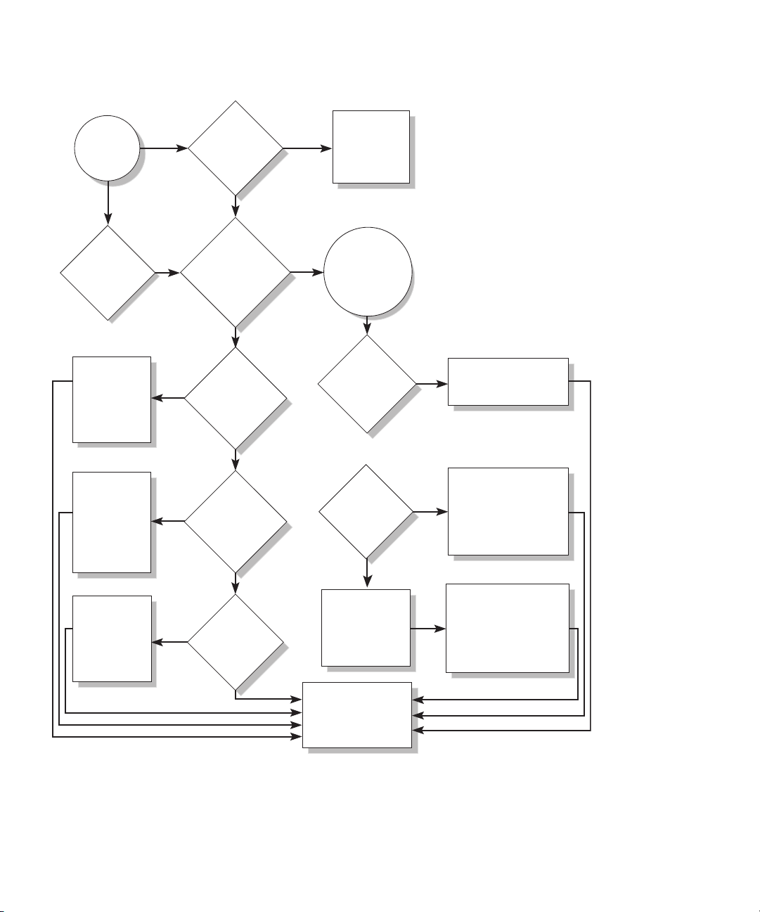
FIGURE 2-1 Diagnostic Flowchart
Faulty
hardware
suspected
Are any
Service
LEDs
0n?
Identify faulty
FRU from the
fault message
and replace
the FRU.
Identify faulty
FRU from the
Sun VTS
message and
replace the
FRU.
1. Are the
Power OK
2. Are any
faults reported
by the ILOM
/SP/faultmgt
command?
the Solaris logs
indicate a faulty
Yes
Sun VTS report
any faulty
Yes
devices?
LEDs
off?
No
No
3. Do
FRU?
No
4. Does
No
show
Yes
command displays
Yes
environmental
Check the
power source
and
connections.
The ILOM
show/SP/
faultmgt
a fault
6. Is
the fault an
fault?
No
7. Is the
fault a PSH
detected
fault?
No
Numbers in this flow chart
correspond to the Action
numbers in Table 2-1.
Identify the fault condition
from the fault message.
Yes
Identify and replace the
faulty FRU from the PSH
message and perform the
Yes
procedure to clear the
PSH detected fault.
Identify faulty
FRU from the
POST message
and replace
the FRU.
Yes
5. Does
POST report
any faulty
devices?
No
8. The fault
is a POST
detected fault.
9. Contact Sun
Support if the fault
condition persists.
2-4 Sun Blade T6320 Server Module Service Manual • June 2009
Identify and replace the
faulty FRU from the POST
message and perform the
procedure to clear the
POST detected faults.
Page 31

TABLE 2-1 Diagnostic Flowchart Actions
Action
No. Diagnostic Action Resulting Action
1.
Check the OK LED. The OK LED is located on the front of the Sun Blade
T6320 server module.
If the LED is not lit, check that the blade is properly
connected and the chassis has power.
2.
Type the ILOM
show
/SP/faultmgmt
command to check
for faults.
The faultmgmt command displays the following
types of faults:
• Environmental faults
• Solaris Predictive Self-Healing (PSH) detected
faults
• POST detected faults
Faulty FRUs are identified in fault messages using
the FRU name. For a list of FRU names, see
TABLE 1-3.
3.
Check the Solaris
log files for fault
information.
The Solaris message buffer and log files record
system events and provide information about faults.
• If system messages indicate a faulty device,
replace the FRU.
• To obtain more diagnostic information, go to
4.
Action
4.
Run the SunVTS
software.
SunVTS can exercise and diagnose FRUs. To run
SunVTS, the server module must be running the
Solaris OS.
• If SunVTS reports a faulty device replace the FRU.
• If SunVTS does not report a faulty device, go to
5.
Action
5.
Run POST. POST performs basic tests of the server module
components and reports faulty FRUs.
• If POST indicates a faulty FRU, replace the FRU.
• If POST does not indicate a faulty FRU, go to
9.
Action
6.
Determine if the
fault is an
environmental
fault.
If the fault listed by the show /SP/faultmgmt
command displays a temperature or voltage fault,
then the fault is an environmental fault.
Environmental faults can be caused by faulty FRUs
(chassis power supply, fan, or blower) or by
environmental conditions such as high ambient
temperature, or blocked airflow.
For more information, see
these sections
Section 2.3, “Interpreting
System LEDs” on page 2-12
Section 2.5.3, “Displaying
System Faults” on
page 2-21
Section 2.8, “Collecting
Information From Solaris
OS Files and Commands”
on page 2-47
Section 2.10, “Exercising
the System With SunVTS”
on page 2-51
Section 2.6, “Running
POST” on page 2-31
Section 2.5.3, “Displaying
System Faults” on
page 2-21
See the Modular System
Service Manual, 820-0051.
Chapter 2 Sun Blade T6320 Server Module Diagnostics 2-5
Page 32

TABLE 2-1 Diagnostic Flowchart Actions (Continued)
Action
No. Diagnostic Action Resulting Action
7.
Determine if the
fault was detected
by PSH.
If the fault message displays the following text, the
fault was detected by the Solaris Predictive SelfHealing software:
Host detected fault
If the fault is a PSH detected fault, identify the faulty
FRU from the fault message and replace the faulty
FRU.
After the FRU is replaced, perform the procedure to
clear PSH detected faults.
8.
Determine if the
fault was detected
by POST.
POST performs basic tests of the server module
components and reports faulty FRUs. When POST
detects a faulty FRU, it logs the fault and if possible
takes the FRU offline. POST detected FRUs display
the following text in the fault message:
FRU-name deemed faulty and disabled
In this case, replace the FRU and run the procedure
to clear POST detected faults.
9.
Contact Sun for
support.
The majority of hardware faults are detected by the
server module diagnostics. In rare cases it is possible
that a problem requires additional troubleshooting.
If you are unable to determine the cause of the
problem, contact Sun for support.
For more information, see
these sections
Section 2.7, “Using the
Solaris Predictive SelfHealing Feature” on
page 2-42
Section 4.2, “Common
Procedures for Parts
Replacement” on page 4-3
Section 2.7.2, “Clearing
PSH Detected Faults” on
page 2-45
Section 2.7.3, “Clearing the
PSH Fault From the ILOM
Logs” on page 2-46
Section 2.6, “Running
POST” on page 2-31
Section 4.2, “Common
Procedures for Parts
Replacement” on page 4-3
Section 2.6.4, “Clearing
POST Detected Faults” on
page 2-39
Sun Support information:
http://www.sun.com/
support
Section 1.3, “Finding the
Serial Number” on
page 1-11
2-6 Sun Blade T6320 Server Module Service Manual • June 2009
Page 33

2.2 Memory Configuration and Fault Handling
New dual rank fully-buffered (FB) DIMMs replace the single rank FB-DIMMs. The
Sun Blade T6320 server module has 16 connectors (slots) that hold Sun approved,
industry standard FB-DIMMs in the following capacities:
■ 1 Gbyte (maximum of 16 Gbytes)
■ 2 Gbyte (maximum of 32 Gbytes)
■ 4 Gbyte (maximum of 64 Gbytes)
■ 8 Gbyte (maximum of 128 Gbytes)
The Sun Blade T6320 server module performs best if all 16 connectors are populated
with 16 identical FB-DIMMs. This configuration also enables the system to continue
operating even when a FB-DIMM fails, or if an entire channel fails.
Note – Only dual rank type DIMMs are available as an assemble to order (ATO)
option.
2.2.1 FB-DIMM Configuration Guidelines
You must follow these guidelines when adding or replacing FB-DIMMs:
■ Valid quantities of FB-DIMMs are 4, 8, or 16 (See FIGURE 2-3).
■ All FB-DIMMs in the server must be the same capacity.
■ All FB-DIMMs in a branch must have the same part number.
Note – FB-DIMMs that run on 1.5V are not supported in this server. An FB-DIMM
that runs on 1.5V is sometimes noted with an LV on the part number label. Do not
install these FB-DIMMs in this server.
When Upgrading Memory
When adding memory to the server, ensure that you follow all of the guidelines. You
might need to move some of the original FB-DIMMs to ensure that all FB-DIMMs in
a branch have the same part number.
Chapter 2 Sun Blade T6320 Server Module Diagnostics 2-7
Page 34

When Replacing Faulty FB-DIMMs
Within each branch, ensure that the replacement FB-DIMM has the same part
number as the FB-DIMM you are removing. If you are unable to obtain an FB-DIMM
with the same part number, you might need to replace all FB-DIMMs in the branch
to ensure that they all have the same part number.
The following table lists the supported FB-DIMMs and part numbers.
TABLE 2 Supported FB-DIMMs and Part Numbers
Description Ordered Separately Assembled at Factory
FB-DIMMs Supported at November 2007 Release of the Server Module
1 GB single rank x4 FB-DIMM x 2 (2 GB FB-DIMM Memory Kit) X4200A 4200A
2 GB single rank x4 FB-DIMM x 2 (4 GB FB-DIMM Memory Kit) X4203A 4203A
4 GB dual rank x8 DIMM x 2 (8 GB FB-DIMM Memory Kit) X4204A 4204A
FB-DIMMs Added at October 2008 Release of the Server Module
1 GB dual rank x8 FB-DIMM x 2 (2 GB FB-DIMM Memory Kit) X4200AF 4200AF
2 GB dual rank x8 FB-DIMM x 2 (4 GB FB-DIMM Memory Kit) X4203AF 4203AF
8 GB dual rank x8 FB-DIMM x 2 (16 GB FB-DIMM Memory Kit) X4290AF 4290AF
2.2.1.1 DIMM Installation Rules
Caution – The following FB-DIMM rules must be followed. The server module
might not operate correctly if the FB-DIMM rules are not followed. Always use
DIMMs that have been qualified by Sun.
FB-DIMMs must be installed in groups of four, each of the same capacity.
The following configurations are supported in the Sun Blade T6320 server module:
■ Four FB-DIMMs (Group 1) Channel 0, FB-DIMM connector 0 in all branches must
be populated.
■ Eight FB-DIMMs (Groups 1 and 2)
■ Sixteen FB-DIMMs (Groups 1, 2 and 3)
See Section 4.3.1, “Removing the DIMMs” on page 4-10 for FB-DIMM installation
instructions.
2-8 Sun Blade T6320 Server Module Service Manual • June 2009
FIGURE 2-3 shows where to to install FB-DIMMs in groups of four.
Page 35
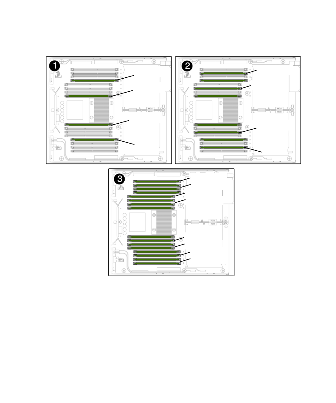
FIGURE 2-3 FB-DIMM Installation Rules
Four DIMMs installed
BR2/CH0/D0
BR3/CH0/D0
BR1/CH0/D0
BR0/CH0/D0
Eight DIMMs installed
BR1/CH1/D0
BR0/CH1/D0
BR2/CH1/D0
BR3/CH1/D0
BR1/CH1/D1
BR1/CH0/D1
BR0/CH1/D1
BR0/CH0/D1
BR2/CH0/D1
BR2/CH1/D1
BR3/CH0/D1
BR3/CH1/D1
Sixteen DIMMs installed
Chapter 2 Sun Blade T6320 Server Module Diagnostics 2-9
Page 36

FIGURE 2-4 DIMM Locate Button and DIMM LEDs
You can also use TABLE 2-2 to identify the DIMMs you want to remove.
TABLE 2-2 FB-DIMM Configuration and Installation
Branch Name Channel Name FRU Name
Motherboard
FB-DIMM
Connector
FB-DIMM
Installation
*
Order
Branch 0 Channel 0 /SYS/MB/CMP0/BR0/CH0/D0 J1001 1 A
/SYS/MB/CMP0/BR0/CH0/D1 J1101 3 B
Channel 1 /SYS/MB/CMP0/BR0/CH1/D0 J1201 2 A
/SYS/MB/CMP0/BR0/CH1/D1 J1301 3 B
Branch 1 Channel 0 /SYS/MB/CMP0/BR1/CH0/D0 J1401 1 C
/SYS/MB/CMP0/BR1/CH0/D1 J1501 3 D
Channel 1 /SYS/MB/CMP0/BR1/CH1/D0 J1601 2 C
/SYS/MB/CMP0/BR1/CH1/D1 J1701 3 D
Branch 2 Channel 0 /SYS/MB/CMP0/BR2/CH0/D0 J2001 1 E
/SYS/MB/CMP0/BR2/CH0/D1 J2101 3 F
Channel 1 /SYS/MB/CMP0/BR2/CH1/D0 J2201 2 E
/SYS/MB/CMP0/BR2/CH1/D1 J2301 3 F
Branch 3 Channel 0 /SYS/MB/CMP0/BR3/CH0/D0 J2401 1 G
2-10 Sun Blade T6320 Server Module Service Manual • June 2009
FB-DIMM
\
Pair
Page 37

TABLE 2-2
FB-DIMM Configuration and Installation (Continued)
Motherboard
Branch Name Channel Name FRU Name
FB-DIMM
Connector
/SYS/MB/CMP0/BR3/CH0/D1 J2501 3 H
Channel 1 /SYS/MB/CMP0/BR3/CH1/D0 J2601 2 G
/SYS/MB/CMP0/BR3/CH1/D1 J2701 3 H
* Upgrade path: DIMMs should be added with each group populated in the order shown.
\ Fault replacement path: Each pair is addressed as a unit, and each pair must be identical.
2.2.1.2 Memory Fault Handling
The Sun Blade T6320 server module uses advanced ECC technology, also called chipkill,
that corrects up to 4-bits in error on nibble boundaries, as long as they are all in the same
DRAM. If a DRAM fails, the DIMM continues to function.
Note – The chipkill function is only supported on DIMMs that use “x4” DRAMs.
The following server module features manage memory faults independently.
■ POST – Runs when the server module is powered on (based on configuration
variables) and thoroughly tests the memory subsystem.
If a memory fault is detected, POST displays the fault with the FRU name of the
faulty DIMMs, logs the fault, and disables the faulty DIMMs by placing them in
the Automatic System Recovery (ASR) blacklist. For a given memory fault, POST
disables half of the physical memory in the system. When this occurs, you must
replace the faulty DIMMs based on the fault message and enable the disabled
DIMMs with the ILOM command set /SYS/component component_state=
enabled .
■ Solaris Predictive Self-healing (PSH) technology – A feature of the Solaris OS,
uses the fault manager daemon (fmd) to watch for various kinds of faults. When
a fault occurs, the fault is assigned a unique fault ID (UUID), and logged. PSH
reports the fault and provides a recommended proactive replacement for the
DIMMs associated with the fault.
FB-DIMM
Installation
*
Order
FB-DIMM
\
Pair
2.2.1.3 Troubleshooting Memory Faults
If you suspect that the server module has a memory problem, follow the flowchart
(see
FIGURE 2-1). Type the ILOM command: show /SP/faultmgmt . The
faultmgmt command lists memory faults and lists the specific DIMMs that are
Chapter 2 Sun Blade T6320 Server Module Diagnostics 2-11
Page 38

associated with the fault. Once you have identified which DIMMs to replace, see
Chapter 4 for DIMM removal and replacement instructions. You must perform the
instructions in that chapter to clear the faults and enable the replaced DIMMs.
2.3 Interpreting System LEDs
The Sun Blade T6320 server module has LEDs on the front panel and the hard
drives. The behavior of LEDs on your server module conforms to the American
National Standards Institute (ANSI) Status Indicator Standard (SIS). These standard
LED behaviors are described in
2.3.1 Front Panel LEDs and Buttons
The front panel LEDs and buttons are located in the center of the server module
(
FIGURE 2-5, TABLE 2-3, and TABLE 2-4, and TABLE 2-5).
TABLE 2-3
2-12 Sun Blade T6320 Server Module Service Manual • June 2009
Page 39

FIGURE 2-5 Front Panel and Hard Drive LEDs
Front View
White - Locator LED
(press to reset the LED)
Blue - Ready to Remove LED
Amber - Service Action Required LED
Green - OK LED
Power button
NMI (non-maskable interrupt
for service use only)
Universal Connector Port (UCP)
Green - Drive OK LED
Amber - Drive Service Action Required LED
Blue - Drive Ready to Remove LED
.
TABLE 2-3 LED Behavior and Meaning
LED Behavior Meaning
Off The condition represented by the color is not true.
Steady on The condition represented by the color is true.
Standby blink The system is functioning at a minimal level and ready to resume full
function.
Slow blink Transitory activity or new activity represented by the color that is
taking place.
Fast blink Attention is required.
Feedback flash Activity is taking place commensurate with the flash rate (such as
disk drive activity).
The LEDs have assigned meanings, described in TABLE 2-4.
Chapter 2 Sun Blade T6320 Server Module Diagnostics 2-13
Page 40

TABLE 2-4 LED Behaviors With Assigned Meanings
Color Behavior Definition Description, Actions, and ILOM Commands
White Off Steady state
Fast blink 4 Hz repeating
sequence, equal
intervals On and
Off.
This indicator helps you to locate a particular enclosure, board, or
subsystem (for example, the Locator LED). The LED is activated
using one of the following methods:
• Type the ILOM command: set /SYS/LOCATE value=on
• Press the button to toggle the indicator on or off.
This LED provides the following indications:
• Off– Normal operating state.
Fast blink – The server module received a signal as a result of one
of the preceding methods and is indicating that the server module
is active.
• Type the ILOM command:
set /SYS/LOCATE value=Fast_Blink
Blue Off Steady state Steady state - If LED is off, it is not safe to remove the server
module from the chassis. You must use software to take the
component offline or shut down the server.
Steady on Steady state If the blue LED is on, a service action can be safely performed on
the component.
To remove a server module (and illuminate the blue LED), type:
set /SYS/ prepare_to_remove_action=true
To remove a hard drive, use the Solaris cfgadm command
Amber Off Steady state
Steady on Steady state This indicator signals the existence of a fault condition. Service is
required (for example, the Service Required LED). The ILOM
show /SP/faultmgmt command provides details about any
faults that cause this indicator to be lit. To turn off an amber LED,
type: set /SYS/return_to_service_action=True
Green Off Steady state Off – The system is unavailable. Either it has no power or ILOM is
not running.
2-14 Sun Blade T6320 Server Module Service Manual • June 2009
Page 41

TABLE 2-4 LED Behaviors With Assigned Meanings (Continued)
Color Behavior Definition Description, Actions, and ILOM Commands
Standby
blink
Repeating sequence
consisting of a brief
(0.1 sec.) on flash
The system is running at a minimum level and is ready to be
quickly revived to full function (for example, the System Activity
LED).
followed by a long
off period (2.9 sec.)
Steady on Steady state Status normal; system or component functioning with no service
actions required.
Slow blink A transitory (temporary) event is taking place for which direct
proportional feedback is not needed or not feasible.
ILOM is enabled but the server module is not fully powered on.
Indicates that the service processor is running while the system is
running at a minimum level in standby mode and ready to be
returned to its normal operating state.
TABLE 2-5 Front Panel Buttons
Button Color Description
Power button gray Turns the host system on and off. Use a paper clip or other small
tipped object to completely press this button.
(reset) gray This button does not function on the Sun Blade T6320 server
module.
Chapter 2 Sun Blade T6320 Server Module Diagnostics 2-15
Page 42

2.3.2 Ethernet Port LEDs
For information about Ethernet LEDs see the service manual for your modular
system chassis or ethernet device at:
http://docs.sun.com/app/docs/prod/blade.6000mod
2.4 Using ILOM for Diagnosis and Repair Verification
The Sun Integrated Lights Out Manager (ILOM) is contained on firmware on the
service processor in the Sun Blade T6320 server module. ILOM enables you to
remotely manage and administer your server module.
Note – ILOM also contains an ALOM-CMT compatibility shell. For more
information about ALOM-CMT compatibility see the Sun Integrated Lights Out
Manager 2.0 Supplement for Sun Blade T6320 Server Modules, 820-2546. Appendix D of
this service manual also provides some information about the ALOM CMT CLI.
ILOM enables you to run remote diagnostics such as power-on self-test (POST), that
would otherwise require physical proximity to the server module serial port. You
can also configure ILOM to send email alerts of hardware failures, hardware
warnings, and other events related to the server module or to ILOM.
The ILOM circuitry runs independently of the server module, using the server
module standby power. Therefore, ILOM firmware and software continue to
function when the server module operating system goes offline or when the server
module is powered off.
Faults detected by ILOM, POST, and the Solaris Predictive Self-healing (PSH)
technology are forwarded to ILOM for fault handling (
In the event of a system fault, ILOM ensures that the Service Action Required LED is
lit, FRU ID PROMs are updated, the fault is logged, and alerts are displayed (faulty
FRUs are identified in fault messages using the FRU name. For a list of FRU names,
see
TABLE 1-3).
2-16 Sun Blade T6320 Server Module Service Manual • June 2009
FIGURE 2-6).
Page 43
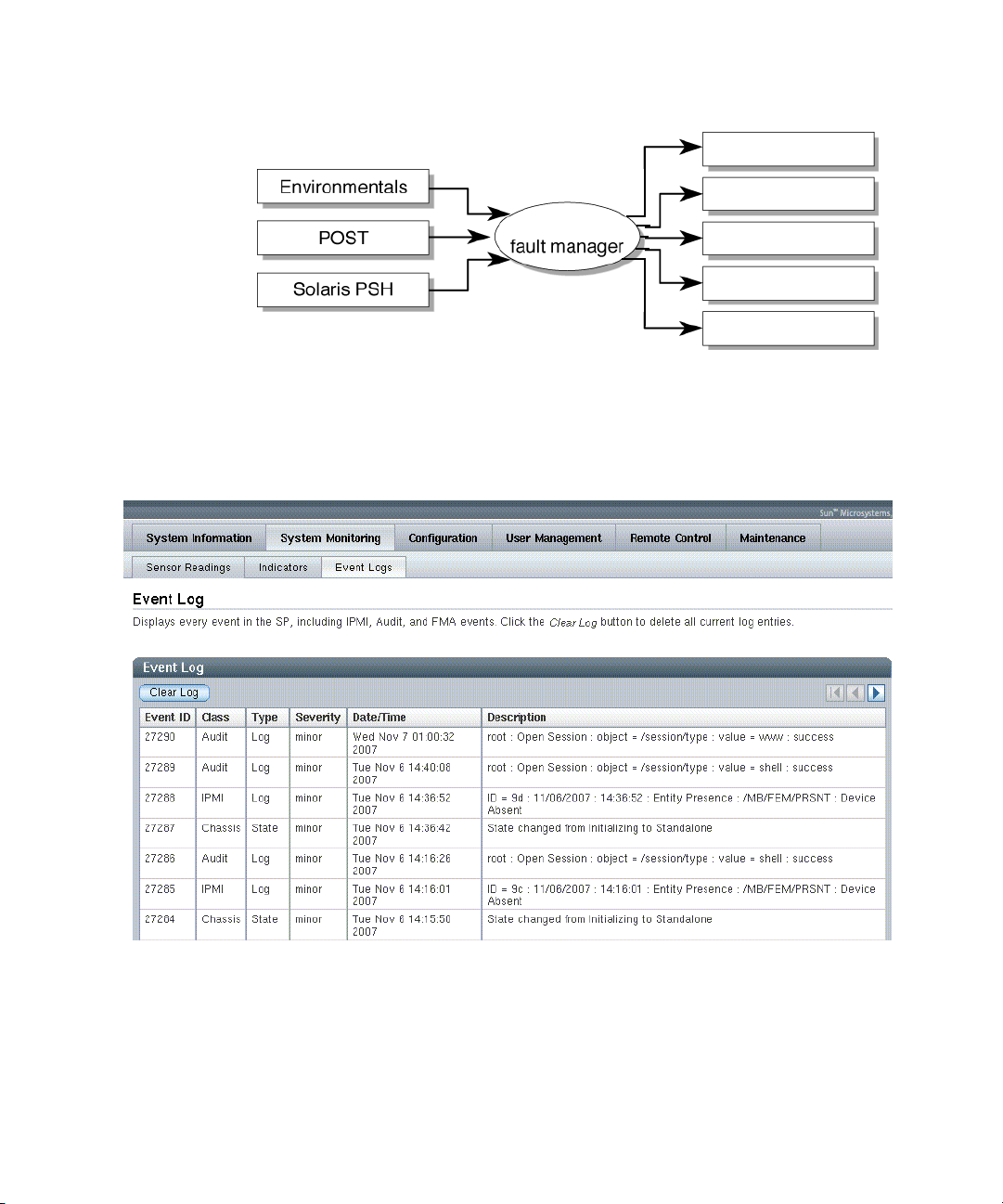
FIGURE 2-6 ILOM Fault Management
In ILOM you can view the ILOM logs to see alerts. FIGURE 2-7 is a sample of the
ILOM web interface. Using the CLI you can type the show
/SP/logs/event/list/ command.
FIGURE 2-7 Sample Event Log in ILOM Web Interface
ILOM
Service Required LED
FRU LEDs
FRUID PROMs
Event Logs
Alerts
ILOM can detect when a fault is no longer present and clears the fault in several
ways:
■ Fault recovery – The system automatically detects that the fault condition is no
longer present. ILOM extinguishes the Service Action Required LED and updates
the FRU PROM.
Chapter 2 Sun Blade T6320 Server Module Diagnostics 2-17
Page 44

Many environmental faults can automatically recover. For example, a temperature
that is exceeding a threshold might return to normal limits, when you connect a
fan. The recovery of environmental faults is automatically detected. Recovery
events are reported using one of two forms:
■ fru at location is OK.
■ sensor at location is within normal range.
There are three thresholds for an environmental fault:
■ Warning: ILOM issues a command to burst the fan speed.
■ Soft shutdown: ILOM initiates a graceful shutdown.
■ Hard shutdown: Immediate shutdown.
Environmental faults can be repaired through hot removal of the faulty FRU. The
FRU removal is automatically detected by the environmental monitoring and all
faults associated with the removed FRU are cleared. The message for that case,
and the alert sent for all FRU removals is:
fru at location has been removed.
■ Fault repair – The fault has been repaired by human intervention. In most cases,
ILOM detects the repair and extinguishes the Service Required LED. In the event
that ILOM does not perform these actions, you must perform these tasks
manually with the following commands:
■ set /SYS/clear_fault_action=true (The ALOM-CMT equivalent is
clearfault) Clears the PSH fault logs but does not enable the component.
See Section 2.7.2, “Clearing PSH Detected Faults” on page 2-45.
■ set /SYS/component/component_state=enabled (The ALOM-CMT
equivalent is enablecomponent) Clears POST generated faults and enables
the component. See Section 2.6.4, “Clearing POST Detected Faults” on
page 2-39.
2.5 Using the ILOM Web Interface For Diagnostics
These instructions use the ILOM web interface. To use the command line interface
(CLI), see Appendix D of this manual, theSun Integrated Lights Out Manager 2.0
Supplement for Sun Blade T6320 Server Modules, or the Sun Integrated Lights out
Manager 2.0 User’s Guide.
2-18 Sun Blade T6320 Server Module Service Manual • June 2009
Page 45

1. Connect to the ILOM web interface by typing the IP address for the Sun Blade
T6320 server module service processor in a web browser.
If you do not know the IP address for the server module, you can obtain the
service processor IP address from the following:
■ ILOM CLI: ->show /SP/network
■ ALOM-CMT compatibility shell: sc> showsc
■ Chassis CMM ILOM: ->show /CH/BLx/SP/network (Where BLx is the
number of the blade server module in the chassis.)
2. Type the username and password to access the diagnostics menus in the ILOM
web interface. The default user name is root, and the default password is
changeme
FIGURE 2-8 ILOM Login Screen
2.5.1 Changing POST Settings With the ILOM Web Interface
There are two tabs in the web interface to control the POST settings:
Chapter 2 Sun Blade T6320 Server Module Diagnostics 2-19
Page 46

1. Select the Remote Control tab and the Diagnostics tab (FIGURE 2-9).
2. Set the verbosity level, trigger, and other settings as needed.
TABLE 2-6 shows how different settings produce POST output.
FIGURE 2-9 Setting POST Diagnostics Levels With the ILOM Web Based Interface
3. To set the diagnostics mode, select the Remote Control tab and the Keyswitch
tab.
2-20 Sun Blade T6320 Server Module Service Manual • June 2009
Page 47

2.5.2 Changing POST Settings With the ILOM CLI
1. Type the show command to see the current POST settings:
-> show /HOST/diag
/HOST/diag
Targets
Properties:
level = max
mode = normal
trigger = power-on-reset error-reset
verbosity = normal
Commands:
cd
set
show
2. Change the POST settings with the set /HOST/diag command.
For example:
-> set /HOST/diag level=min
Set ’level’ to ’min’
-> set /HOST/diag mode=Normal
Set ’mode’ to ’Normal’
-> set /HOST/diag verbosity=max
Set ’verbosity’ to ’max’
-> set /HOST/diag trigger=power-on-reset trigger=error-reset
Set ’trigger’ to ’power-on-reset’
Set ’trigger’ to ’error-reset’
2.5.3 Displaying System Faults
ILOM displays the following faults with the web interface and CLI:
■ Environmental faults – Temperature or voltage problems that might be caused by
faulty FRUs (power supplies, fans, or blower), or by room temperature or blocked
air flow.
■ POST detected faults – Detected by the power-on self-test diagnostics.
■ PSH detected faults – Detected by the Solaris Predictive Self-healing (PSH)
technology
Chapter 2 Sun Blade T6320 Server Module Diagnostics 2-21
Page 48
Use the web interface or type the show /SP/faultmgmt command for the
following reasons:
■ To see if any faults have been passed to, or detected by the ILOM firmware.
■ To obtain the fault message ID (SUNW-MSG-ID) for PSH detected faults.
■ To verify that the replacement of a FRU has cleared the fault and not generated
any additional faults.
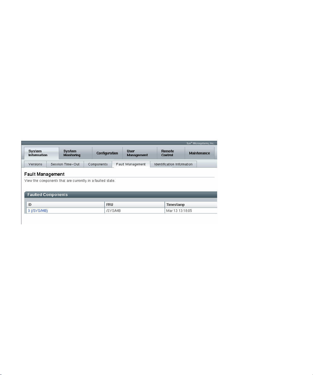
2.5.3.1 Viewing Fault Status Using the ILOM Web Interface
In the ILOM web interface, you can view the system components currently in a fault
state using the Fault Management page.
FIGURE 2-10 Fault Management Page Example
The Fault Management page lists faulted components by ID, FRU, and TimeStamp.
You can access additional information about the faulted component by clicking the
faulted component ID. For example, if you clicked the faulted component ID, 0
SYS/MB/, the following dialog window appears displaying additional details about
the faulted component.
2-22 Sun Blade T6320 Server Module Service Manual • June 2009
Page 49

FIGURE 2-11 Faulted Component ID Window
Alternatively, in the ILOM web interface, you can identify the fault status of a
component on the Component Management page.
FIGURE 2-12 Component Management Page - Fault Status
2.5.3.2 Viewing Fault Status Using the ILOM CLI
In the ILOM CLI, you can view the fault status of component(s) by using the show
command. For example:
Chapter 2 Sun Blade T6320 Server Module Diagnostics 2-23
Page 50

->show /SP/faultmgmt
2.5.4 Displaying the Environmental Status with the ILOM CLI
The ILOM show command displays a snapshot of the server module environmental
status. This command displays system temperatures, hard drive status, power
supply and fan status, front panel LED status, voltage, and current sensors. The
output uses a format similar to the Solaris OS command prtdiag (1M).
At the -> prompt, type the show command.
The output differs according to your system model and configuration.
-> show /SYS/MB/V_VCORE
/SYS/MB/V_VCORE
Targets:
Properties:
type = Voltage
class = Threshold Sensor
value = 1.224 Volts
upper_nonrecov_threshold = 1.38 Volts
upper_critical_threshold = 1.34 Volts
upper_noncritical_threshold = 1.32 Volts
lower_noncritical_threshold = 1.15 Volts
lower_critical_threshold = 1.12 Volts
lower_nonrecov_threshold = 1.08 Volts
Commands:
cd
show
Note – Some environmental information might not be available when the server
module is in standby mode.
2-24 Sun Blade T6320 Server Module Service Manual • June 2009
Page 51

2.5.5 Displaying the Environmental Status and Sensor Readings with the ILOM Web Interface
1. Open a web browser and type the IP address of the server module service
processor in the browser.
2. Select the top System Monitoring tab and the lower Sensor Readings tab
(
FIGURE 2-13).
3. Double click on the sensor reading that you want to check (
FIGURE 2-13 Obtaining Sensor Readings and Environmental Status With the ILOM Web Interface
FIGURE 2-13).
Chapter 2 Sun Blade T6320 Server Module Diagnostics 2-25
Page 52

FIGURE 2-14 Sensor Reading Window for an FB-DIMM in Channel 1
2.5.6 Displaying FRU Information
ILOM can display static FRU information such as the FRU manufacturer, serial
number and some FRU status information (
FIGURE 2-15).
Note – To view dynamic FRU information you must type the ALOM CMT showfru
command. The dynamic FRU information provides more details about FRUs.
2.5.6.1 Using the ILOM Web Interface to Display FRU Information
1. Select the System Information and Components tabs.
2. Click on the component to view the FRU information (
2-26 Sun Blade T6320 Server Module Service Manual • June 2009
FIGURE 2-15).
Page 53

FIGURE 2-15 Static FRU Information in the ILOM Web Interface
2.5.6.2 Using the CLI to Display FRU Information
The show /SYS/MB command displays static information about the FRUs in the
server module. Use this command to see information about an individual FRU,
or for all the FRUs.
Chapter 2 Sun Blade T6320 Server Module Diagnostics 2-27
Page 54

● At the -> prompt, type the show command.
In the following example, the show command displays information about the
motherboard (MB).
-> show /SYS/MB
/SYS/MB
Targets:
FEM0
REM0
SEEPROM
SCC_NVRAM
NET
SASHBA
USB0
USB1
T_AMB
CMP0
V_VMEML
V_VMEMR
V_+3V3_STBY
V_VCORE
V_+3V3_MAIN
V_VDDIO
V_+12V0_MAIN
VCORE_POK
VMEML_POK
VMEMR_POK
Properties:
type = Motherboard
fru_name = MB
fru_description = 4C,1.17GHZ N2,T6320,DIRECT-A
fru_manufacturer = Celestica
fru_version = 01_01
fru_part_number = 5407368
fru_serial_number = 1B1174
fault_state = Faulted
clear_fault_action = (none)
Commands:
cd
show
->
This example shows a portion of the more detailed dynamic FRU information
provided by the ALOM CMT showfru command.
2-28 Sun Blade T6320 Server Module Service Manual • June 2009
Page 55

sc> showfru
/SYS/SP (container)
SEGMENT: ST
/Status_CurrentR
/Status_CurrentR/UNIX_Timestamp32: Thu Feb 17 07:25:57 2000
/Status_CurrentR/status: 0x00 (OK)
SEGMENT: TH ...
... ... ...
SEGMENT: FD
/Customer_DataR
/Customer_DataR/UNIX_Timestamp32: Wed Feb 16 08:41:44 GMT 2000
/Customer_DataR/Cust_Data: QT
/InstallationR (1 iterations)
/InstallationR[0]
/InstallationR[0]/UNIX_Timestamp32: Thu Feb 17 07:26:09 GMT 2000
/InstallationR[0]/Fru_Path: /SYS/MB/REM
/InstallationR[0]/Parent_Part_Number: 5017821
/InstallationR[0]/Parent_Serial_Number: 5C00FV
/InstallationR[0]/Parent_Dash_Level: 04
/InstallationR[0]/System_Id: 1005LCB-0709YM00FV
/InstallationR[0]/System_Tz: 0
/InstallationR[0]/Geo_North: 0
/InstallationR[0]/Geo_East: 0
/InstallationR[0]/Geo_Alt: 0
/InstallationR[0]/Geo_Location: GMT
... ... ...
/SYS/MB/CMP0/BR0/CH0/D0 (container)
/SPD/Timestamp: Mon Feb 12 12:00:00 2007
/SPD/Description: DDR2 SDRAM FB-DIMM, 4 GByte
/SPD/Manufacture Location: ff
/SPD/AMB Vendor: IDT
/SPD/Vendor: Micron Technology
/SPD/Vendor Part No: 36HTF51272F667E1D4
/SPD/Vendor Serial No: d2174043
/SPD/Num_Banks: 8
/SPD/Num_Ranks: 2
/SPD/Num_Rows: 14
/SPD/Num_Cols: 11
/SPD/Sdram_Width: 4
/SunSPD/Sun_Serial_Number: 002C010707D2174043
/SunSPD/SPD_Format_Version: 20
/SunSPD/Sun_Part_Dash_Rev: 000-0000-00 Rev 00
/SunSPD/Certified_Platforms: 0x00000001 (OK)
/SunSPD/Sun_Key_Code: 0x0000
/SunSPD/Sun_Certification: NO
/SunSPD/timestamp: Thu Feb 17 07:26:20 2000
/SunSPD/MACADDR: 00:14:4F:98:84:7A
Chapter 2 Sun Blade T6320 Server Module Diagnostics 2-29
Page 56

/SunSPD/status 0x00 (OK)
/SunSPD/Initiator N/A
/SunSPD/Message: No message
/SunSPD/powerupdate: Thu Feb 17 07:01:16 2000
/SunSPD/Poweron_minutes: 1487
/SYS/MB/CMP0/BR1/CH0/D0 (container)
... ... ...
sc>
2.6 Running POST
Use POST to test and verify server module hardware. Power-on self-test (POST) is a
group of PROM-based tests that run when the server module is powered on or reset.
POST checks the basic integrity of the critical hardware components in the server
module (CPU, memory, and I/O buses).
If POST detects a faulty component, it is disabled automatically, preventing faulty
hardware from potentially harming any software. If the system is capable of running
without the disabled component, the system will boot when POST is complete. For
example, if one of the processor cores is deemed faulty by POST, that core will be
disabled, and the system will boot and run using the remaining cores.
You can use POST as an initial diagnostic tool for the system hardware. In this case,
configure POST to run in diagnostic service mode for maximum test coverage and
verbose output.
Note – Devices can be manually enabled or disabled using ASR commands (see
Section 2.9, “Managing Components With Automatic System Recovery Commands”
on page 2-48).
2.6.1 Controlling How POST Runs
The server module can be configured for normal, extensive, or no POST execution.
You can also control the level of tests that run, the amount of POST output that is
displayed, and which reset events trigger POST by using diag variables.
2-30 Sun Blade T6320 Server Module Service Manual • June 2009
Page 57

TABLE 2-6 lists the DIAG variables used to configure POST and FIGURE 2-16 shows
how the variables work together.
TABLE 2-6 Parameters Used For POST Configuration
Parameter Values Description
setkeyswitch
diag_mode off POST does not run.
diag_level min If diag_mode = normal, runs minimum set of
diag_trigger none Does not run POST on reset.
diag_verbosity none No POST output is displayed.
*
*
normal The system can power on and run POST (based
on the other parameter settings). For details see
FIGURE 2-16. This parameter overrides all other
commands.
diag The system runs POST based on predetermined
settings.
stby The system cannot power on.
locked The system can power on and run POST, but no
flash updates can be made.
normal Runs POST according to diag_level value.
service Runs POST with preset values for diag_level
and diag_verbosity.
tests.
max If diag_mode = normal, runs all the minimum
tests plus extensive CPU and memory tests.
user_reset Runs POST upon user-initiated resets.
power_on_reset Only runs POST for the first power on. This is the
default.
error_reset Runs POST if fatal errors are detected.
all_reset Runs POST after any reset.
min POST output displays functional tests with a
banner and pinwheel.
normal POST output displays all test and informational
messages.
max POST displays all test, informational, and some
debugging messages.
Chapter 2 Sun Blade T6320 Server Module Diagnostics 2-31
Page 58

FIGURE 2-16 Flowchart of ILOM Variables for POST Configuration
2-32 Sun Blade T6320 Server Module Service Manual • June 2009
Page 59

TABLE 2-7 shows typical combinations of ILOM variables and associated POST
modes.
TABLE 2-7 POST Modes and Parameter Settings
Parameter
diag_mode normal off service normal
setkeyswitch
diag_level min n/a max max
diag_trigger power-on-reset
diag_verbosity normal n/a max max
Description of POST
execution
* The setkeyswitch parameter, when set to diag, overrides all the other POST variables.
Normal Diagnostic Mode
(default settings) No POST Execution
*
normal normal normal diag
none all-resets all-resets
error-reset
This is the default POST
configuration. This
configuration tests the
system thoroughly, and
suppresses some of the
detailed POST output.
POST does not
run, resulting in
quick system
initialization, but
this is not a
suggested
configuration.
Diagnostic Service
Mode
POST runs the full
spectrum of tests
with the maximum
output displayed.
Keyswitch Diagnostic
Preset Values
POST runs the full
spectrum of tests
with the maximum
output displayed.
2.6.2 Changing POST Parameters
You can use the web interface or the CLI to change the POST parameters.
2.6.2.1 Using the Web Interface to Change POST Parameters
1. From the ILOM web interface, select the Remote Console tab (FIGURE 2-17).
2. Select the Diagnostics Tab.
3. Select the POST settings that you require.
TABLE 2-7 describes how the POST settings will execute.
4. Click the Save button.
Note – If you do not have a console window open, you should open one. POST will
only display output to a console window, not the web interface.
Chapter 2 Sun Blade T6320 Server Module Diagnostics 2-33
Page 60

FIGURE 2-17 Setting POST Parameters With the ILOM Web Interface
5. Select the Remote Power Control Tab.
6. Select a power control setting and Select Save (
2-34 Sun Blade T6320 Server Module Service Manual • June 2009
FIGURE 2-18).
Page 61

FIGURE 2-18 Changing Power Settings with the ILOM Web Interface
When you power cycle the server module, POST runs and displays output to the
service processor console window:
{0} ok Chassis | critical: Host has been powered off
Chassis | major: Host has been powered on
2007-11-07 18:22:19.511 0:0:0>
2007-11-07 18:22:19.560 0:0:0>Sun Blade T6320 Server Module POST 4.27.4
2007/10/02 19:09
/export/delivery/delivery/4.27/4.27.4/post4.27.x/Niagara/glendale/integrated
(root)
2007-11-07 18:22:19.836 0:0:0>Copyright 2007 Sun Microsystems, Inc. All rights
reserved
2007-11-07 18:22:20.001 0:0:0>VBSC cmp 0 arg is: 00ffffff.ffff00ff
2007-11-07 18:22:20.108 0:0:0>POST enabling threads: 00ffffff.ffff00ff
2007-11-07 18:22:20.223 0:0:0>VBSC mode is: 00000000.00000001
2007-11-07 18:22:20.321 0:0:0>VBSC level is: 00000000.00000001
Chapter 2 Sun Blade T6320 Server Module Diagnostics 2-35
Page 62

2007-11-07 18:22:20.421 0:0:0>VBSC selecting Normal mode, MAX Testing.
2007-11-07 18:22:20.533 0:0:0>VBSC setting verbosity level 3
2007-11-07 18:22:20.629 0:0:0> Niagara2, Version 2.1
2007-11-07 18:22:20.714 0:0:0> Serial Number: 0f880060.768660a8
2007-11-07 18:22:20.843 0:0:0>Basic Memory Tests.....
7. Read the POST output to determine if you need to perform service actions.
See Section 2.6.3, “Interpreting POST Messages” on page 2-38.
2.6.2.2 Using the CLI to Change POST Parameters
1. Verify the current post parameters with the show command. Type:
-> show /HOST/diag
/HOST/diag
Targets:
Properties:
level = min
mode = normal
trigger = power-on-reset error-reset
verbosity = normal
Commands:
cd
set
show
->
2. Type the set command to change the POST parameters.
TABLE 2-7 describes how the POST settings will execute. This example shows how
to set the verbosity to max.
-> set /HOST/diag verbosity=max
Set ’verbosity’ to ’max’
->
2-36 Sun Blade T6320 Server Module Service Manual • June 2009
Page 63
3. Power cycle the server module to run POST.
There are several ways to initiate a reset. The following example uses the ILOM
reset command.
-> reset /SYS
Are you sure you want to reset /SYS (y/n)? y
Performing hard reset on /SYS
->
4. Read the POST output to determine if you need to perform service actions. See
Section 2.6.3, “Interpreting POST Messages” on page 2-38.
2.6.3 Interpreting POST Messages
When POST is finished running and no faults were detected, the system will boot.
If POST detects a faulty device, the fault is displayed and the fault information is
passed to ILOM or ALOM CMT for fault handling. Faulty FRUs are identified in
fault messages using the FRU name. For a list of FRU names, see Appendix A.
1. Interpret the POST messages:
POST error messages use the following syntax:
c:s > ERROR: TEST = failing-test
c:s > H/W under test = FRU
c:s > Repair Instructions: Replace items in order listed by H/W
under test above
c:s > MSG = test-error-message
c:s > END_ERROR
In this syntax, c = the core number, s = the strand number.
Warning and informational messages use the following syntax:
INFO or WARNING: message
The following example shows a POST error message report for a missing PCI device:
0:0:0>ERROR: TEST = PIU PCI id test
0:0:0>H/W under test = MB/PCI-SWITCH
0:0:0>Repair Instructions: Replace items in order listed by ‘H/W under test’
above.
0:0:0>MSG = PCI ID test device missing Cont.
DEVICE NAME: MB/PCI-SWITCH
0:0:0>END_ERROR
Chapter 2 Sun Blade T6320 Server Module Diagnostics 2-37
Page 64

2. Type the show /SPfaultmgmt command to obtain additional fault
information.
The fault is captured by ILOM, where the fault is logged. The Service Action
Required LED is lit, and the faulty component is disabled.
For example:
ok #.
->
->
show /SP/faultmgmt
/SP/faultmgmt
Targets:
0 (/SYS/MB/CMP0/BR2/CH1/D1)
Properties:
Commands:
cd
show
In this example, /SYS/MB/CMP0/BR2/CH1/D1 is disabled. The system can
boot using memory that was not disabled until the faulty component is
replaced.
Note – You can use ASR commands to display and control disabled components.
See Section 2.9, “Managing Components With Automatic System Recovery
Commands” on page 2-48.
2.6.4 Clearing POST Detected Faults
In most cases, when POST detects a faulty component, POST logs the fault and
automatically takes the failed component out of operation by placing the component
in the ASR blacklist.
See Section 2.9, “Managing Components With Automatic System Recovery
Commands” on page 2-48).
After the faulty FRU is replaced, you must clear the fault by removing the
component from the ASR blacklist.
2-38 Sun Blade T6320 Server Module Service Manual • June 2009
Page 65

2.6.4.1 Clearing Faults With the Web Interface
This procedure describes how to enable components after a POST fault has been
generated. The POST fault log is not actually cleared.
1. Select the tabs: System Information and Components tabs (
2. Select the radio button for the component that you must clear.
3. In the Actions menu, select: Enable Component.
FIGURE 2-19 Enabling Components With the ILOM Web Interface
FIGURE 2-19).
Note – The Clear Faults command in the Action menu will only clear the PSH-
generated faults, and will not enable a component.
Chapter 2 Sun Blade T6320 Server Module Diagnostics 2-39
Page 66

2.6.4.2 Clearing Faults With the ILOM CLI
1. At the ILOM prompt, type the show /SP/faultmgmt command to identify
POST detected faults.
POST detected faults are distinguished from other faults by the text:
deemed faulty and disabled, and no UUID number is reported.
For example:
-> show /SP/faultmgmt
■ If no fault is reported, you do not need to do anything else. Do not perform the
subsequent steps.
■ If a fault is detected, continue with Step 2.
2. Type the set component_state=enabled command to clear the fault and
remove the component from the ASR blacklist.
Type the FRU name that was reported in the fault in the previous step.
This example shows how to change directory to thread P32 on the CPU and
enable it.
-> cd /SYS/MB/CMP0/P32
/SYS/MB/CMP0/P32
-> show
/SYS/MB/CMP0/P32
Targets:
Properties:
type = CPU thread
component_state = Disabled
Commands:
cd
show
-> set component_state=enabled
Set ’component_state’ to ’enabled’
The fault is cleared and should not show up when you type the show
/SP/faultmgmt command. Additionally, the Service Action Required LED is no
longer illuminated.
3. Reboot the server module.
You must reboot the server module for the enablecomponent command to take
effect.
2-40 Sun Blade T6320 Server Module Service Manual • June 2009
Page 67

4. At the ILOM prompt, type the show /SP/faultmgmt command to verify that
no faults are reported.
-> show /SP/faultmgmt
Last POST run: THU MAR 09 16:52:44 2006
POST status: Passed all devices
No failures found in System
2.6.4.3 Clearing Faults Manually with ILOM
The ILOM set /SYS/clear_fault_action=enabled command allows you to
manually clear certain types of faults without replacing a FRU. It also allows you to
clear a fault if ILOM was unable to automatically detect the FRU replacement.
2.6.4.4 Clearing Hard Drive Faults
ILOM can detect hard drive replacement. However, to configure and unconfigure a
hard drive, you must type the Solaris cfgadm command. See Section 3.2, “Hot-
Plugging a Hard Drive” on page 3-1. ILOM does not handle hard drive faults. Use
the Solaris message files to view hard drive faults. See Section 2.8, “Collecting
Information From Solaris OS Files and Commands” on page 2-47.
2.7 Using the Solaris Predictive Self-Healing Feature
The Solaris Predictive Self-Healing (PSH) technology enables the Sun Blade T6320
server module to diagnose problems while the Solaris OS is running. Many
problems can be resolved before they negatively affect operations.
The Solaris OS uses the fault manager daemon, fmd(1M), which starts at boot time
and runs in the background to monitor the system. If a component generates an
error, the daemon handles the error by correlating the error with data from previous
errors and other related information to diagnose the problem. Once diagnosed, the
fault manager daemon assigns the problem a Universal Unique Identifier (UUID)
that distinguishes the problem across any set of systems. When possible, the fault
manager daemon initiates steps to self-heal the system and take the component
offline. The daemon also logs the fault to the syslogd daemon and provides a fault
notification with a message ID (MSGID). You can use the message ID to get
additional information about the problem from Sun’s knowledge article database.
Chapter 2 Sun Blade T6320 Server Module Diagnostics 2-41
Page 68

The Predictive Self-Healing technology covers the following Sun Blade T6320 server
module components:
■ UltraSPARC
■ Memory
■ I/O bus
®
T2 multicore processor (CPU)
The PSH console message provides the following information:
■ Type
■ Severity
■ Description
■ Automated response
■ Impact
■ Suggested action for system administrator
If the Solaris PSH facility has detected a faulty component, type the fmdump
command to identify the fault. Faulty FRUs are identified in fault messages using
the FRU name. For a list of FRU names, see Appendix A.
Note – Additional Predictive Self-Healing information is available at:
http://www.sun.com/msg
2.7.1 Identifying Faults With the fmadm faulty and fmdump Commands
2.7.1.1 Using the fmadm faulty Command
Type the fmadm faulty command to identify a faulty component.
1. Type fmadm faulty.
# fmdadm faulty
STATE RESOURCE /UUID
faulted cpu:///cpuid=8/serial=FAC006AE4515C47
8856153f-6f9b-47c6-909a-b05180f53c07
The output shows the UUID of the related fault and provides information for
clearing the fault.
2-42 Sun Blade T6320 Server Module Service Manual • June 2009
Page 69

2. Use the output of this command to clear the fault as shown in Section 2.7.2,
“Clearing PSH Detected Faults” on page 2-45.
If fmadm faulty does not identify a faulty component or if you need more
detailed information, type the fmdump command.
2.7.1.2 Using the fmdump Command
The fmdump command displays the list of faults detected by the Solaris PSH facility.
Use this command for the following reasons:
■ To see if any faults have been detected by the Solaris PSH facility.
■ To obtain the fault message ID (SUNW-MSG-ID) for detected faults.
■ To verify that the replacement of a FRU has not generated any additional faults.
If you already have a fault message ID, go to Step 2 to obtain more information
about the fault from the Sun Predictive Self-Healing Knowledge Article web site.
Note – Faults detected by the Solaris PSH facility are also reported through ILOM
alerts. In addition to the PSH fmdump command, the ILOM show /SYS/ command
also provides information about faults and displays fault UUIDs. See Section 2.5.3,
“Displaying System Faults” on page 2-21.
1. Check the event log by typing the fmdump command with -v for verbose
output.
For example:
# fmdump -v
TIME UUID SUNW-MSG-ID
Apr 24 06:54:08.2005 lce22523-lc80-6062-e61d-f3b39290ae2c SUN4V8000-6H
100% fault.cpu.ultraSPARCT2l2cachedata
FRU:hc:///component=MB
rsrc: cpu:///cpuid=0/serial=22D1D6604A
In this example, a fault is displayed, indicating the following details:
■ Date and time of the fault (Apr 24 06:54:08.2005)
■ Universal Unique Identifier (UUID) that is unique for every fault (lce22523-
lc80-6062-e61d-f3b39290ae2c)
■ Sun message identifier (SUNW4V-8000-6H) that can be used to obtain additional
fault information
■ Faulted FRU (FRU:hc:///component=MB). In this example it is identified as MB,
indicating that the motherboard requires replacement.
2. Use the Sun message ID to obtain more information about this type of fault.
Chapter 2 Sun Blade T6320 Server Module Diagnostics 2-43
Page 70

a. In a browser, go to the Predictive Self-Healing Knowledge Article web site:
http://www.sun.com/msg
b. Type the message ID in the SUNW-MSG-ID field, and press Lookup.
In this example, the message ID SUN4U-8000-6H returns the following
information for corrective action:
CPU errors exceeded acceptable levels
Type
Fault
Severity
Major
Description
The number of errors associated with this CPU has exceeded
acceptable levels.
Automated Response
The fault manager will attempt to remove the affected CPU from
service.
Impact
System performance may be affected.
Suggested Action for System Administrator
Schedule a repair procedure to replace the affected CPU, the
identity of which can be determined using fmdump -v -u <EVENT_ID>.
Details
The Message ID: SUN4U-8000-6H indicates diagnosis has
determined that a CPU is faulty. The Solaris fault manager arranged
an automated attempt to disable this CPU. The recommended action
for the system administrator is to contact Sun support so a Sun
service technician can replace the affected component.
c. Follow the suggested actions to repair the fault.
2.7.2 Clearing PSH Detected Faults
When the Solaris PSH facility detects faults, the faults are logged and displayed on
the console. After the fault condition is corrected, for example by replacing a faulty
FRU, you might have to clear the fault.
Note – If you are diagnosing or replacing faulty DIMMs, do not follow this
procedure. Instead, perform the procedure in Section 4.3.2, “Replacing the DIMMs”
on page 4-14.
2-44 Sun Blade T6320 Server Module Service Manual • June 2009
Page 71

1. After replacing a faulty FRU, boot the system.
2. Type fmadm faulty:
# fmdadm faulty
STATE RESOURCE /UUID
faulted cpu:///cpuid=8/serial=FAC006AE4515C47
8856153f-6f9b-47c6-909a-b05180f53c07
3. Clear the fault from all persistent fault records.
In some cases, even though the fault is cleared, some persistent fault information
remains and results in erroneous fault messages at boot time. To ensure that these
messages are not displayed, perform the following command:
fmadm repair UUID
For example:
# fmadm repair cpu:///cpuid=8/serial=FAC006AE4515C47
fmadm: recorded repair to cpu:///cpuid=8/serial=FAC006AE4515C47
# fmadm faulty
STATE RESOURCE/UUID
Note – You can also use the FRU fault UUID instead of the Fault Management
Resource Identifier (FMRI).
Typing fmadm faulty after the repair command verifies that there are no more
faults.
2.7.3 Clearing the PSH Fault From the ILOM Logs
When the Solaris PSH facility detects faults, the faults are also logged by the ILOM
software.
Note – If you clear the faults using Solaris PSH, you do not have to clear the faults
in ILOM. If you clear the faults in ILOM, you do not also have to clear them with
Solaris PSH.
Note – If you are diagnosing or replacing faulty DIMMs, do not follow this
procedure. Instead, perform the procedure in Section 4.3.2, “Replacing the DIMMs”
on page 4-14.
Chapter 2 Sun Blade T6320 Server Module Diagnostics 2-45
Page 72

1. After replacing a faulty FRU, at the ILOM prompt, type the ILOM -> show
faults command to identify PSH detected faults.
PSH detected faults are distinguished from other faults by the text:
Host detected fault.
For example:
-> show /SP/faultmgmt
■ If no fault is reported, you do not need to do anything else.
■ If the fault is reported, continue with Step 2.
2. Type the clear_fault command with the UUID provided in the showfaults
output:
-> set /SYS/component clear_fault_action=true
Clearing fault from component...
Fault cleared.
2.8 Collecting Information From Solaris OS Files and Commands
With the Solaris OS running on the Sun Blade T6320 server module, you have all the
Solaris OS files and commands available for collecting information and for
troubleshooting.
In the event that POST, ILOM, or the Solaris PSH features did not indicate the source
of a fault, check the message buffer and log files for fault notifications. Hard drive
faults are usually captured by the Solaris message files.
Type the syslogd command to view the most recent system message.
Use the /var/adm/messages file to view the system messages log file.
2.8.1 Checking the Message Buffer
1. Log in as superuser.
2-46 Sun Blade T6320 Server Module Service Manual • June 2009
Page 73

2. Type the syslogd command.
# syslogd
The syslogd command displays the most recent messages generated by the
system.
2.8.2 Viewing the System Message Log Files
The error logging daemon, syslogd, automatically records various system
warnings, errors, and faults in message files. These messages can alert you to system
problems such as a device that is about to fail.
The /var/adm directory contains several message files. The most recent messages
are in the /var/adm/messages file. After a period of time (usually every ten days),
a new messages file is automatically created. The original contents of the
messages file are rotated to a file named messages.1. Over a period of time, the
messages are further rotated to messages.2 and messages.3, and then deleted.
1. Log in as superuser.
2. Type the following command.
# more /var/adm/messages
3. If you want to view all logged messages, type this command.
# more /var/adm/messages*
2.9 Managing Components With Automatic System Recovery Commands
The Automatic System Recovery (ASR) feature enables the server module to
automatically unconfigure failed components to remove them from operation until
they can be replaced. In the Sun Blade T6320 server module, the following
components are managed by the ASR feature:
■ UltraSPARC T2 processor strands
■ Memory DIMMs
■ I/O bus
Chapter 2 Sun Blade T6320 Server Module Diagnostics 2-47
Page 74

The database that contains the list of disabled components is called the ASR blacklist
(asr-db).
In most cases, POST automatically disables a component when it is faulty. After the
cause of the fault is repaired (FRU replacement, loose connector reseated, and so on),
you must remove the component from the ASR blacklist.
The ASR commands (
TABLE 2-8) enable you to view and manually add or remove
components from the ASR blacklist. These commands are run from the ILOM ->
prompt. For information about ALOM CMT commands, see the Sun Integrated Lights
Out Manager 2.0 Supplement for Sun Blade T6320 Server Modules, 820-2546.
TABLE 2-8 ASR Commands
ILOM Web
Interface ILOM Command ALOM Command Description
Select the
following tabs:
System
Information,
Components,
Actions,
then select the
action.
No equivalent in ILOM clearasrdb Removes all entries
* The showcomponent command might not report all blacklisted DIMMs.
show /SYS/component
component_state
set /SYS/component
component_state=enabled
set /SYS/component
component_state=disabled
showcomponent
enablecomponent asrkey Removes a
disablecomponent asrkey Adds a component to
*
Displays system
components and
their current state.
component from the
asr-db blacklist,
where asrkey is the
component to enable.
the asr-db blacklist,
where asrkey is the
component to
disable.
from the asr-db
blacklist.
Note – The components (asrkeys) vary from system to system, depending on how
many cores and memory are present. Type the showcomponent command to see the
asrkeys on a given system.
Note – A reset or powercycle is required after disabling or enabling a
component. If the status of a component is changed with power on there is no effect
to the system until the next reset or powercycle.
2-48 Sun Blade T6320 Server Module Service Manual • June 2009
Page 75

2.9.1 Displaying System Components With the show /SYS Command
To see examples of ILOM web interface and CLI commands that show component
status, see Section 2.5.4, “Displaying the Environmental Status with the ILOM CLI”
on page 2-24.
The show command displays the system components (asrkeys) and reports their
status.
1. At the -> prompt, type the show command.
An example with no disabled components.
-> show /SYS/MB/USB0
/SYS/MB/USB0
Targets:
Properties:
type = USB Port
component_state = Enabled
Commands:
cd
show
->
An example showing a disabled component:
-> show /SYS/MB/USB0
/SYS/MB/USB0
Targets:
Properties:
type = USB Port
component_state = Disabled
Commands:
cd
show
Chapter 2 Sun Blade T6320 Server Module Diagnostics 2-49
Page 76

2.10 Exercising the System With SunVTS
Sometimes a system exhibits a problem that cannot be isolated definitively to a
particular hardware or software component. In such cases, it might be useful to run
a diagnostic tool that stresses the system by continuously running a comprehensive
battery of tests. Sun provides the SunVTS software for this purpose.
2.10.1 Checking SunVTS Software Installation
This procedure assumes that the Solaris OS is running on the Sun Blade T6320 server
module, and that you have access to the Solaris command line.
1. Check for the presence of SunVTS packages using the pkginfo command.
# pkginfo | grep -i vts
system SUNWvts SunVTS Framework
system SUNWvtsmn SunVTS Manufacturing package
system SUNWvtsr SunVTS Framework (root)
system SUNWvtsts SunVTS for Tests
#
■ If SunVTS software is loaded, information about the packages is displayed.
■ If SunVTS software is not loaded, no information is displayed.
TABLE 2-9 lists some SunVTS packages.
TABLE 2-9 Sample of installed SunVTS Packages
Package Description
SUNWvts SunVTS framework
SUNWvtsr SunVTS Framework (root)
SUNWvtsts SunVTS for tests
SUNWvtsmn SunVTS man pages
If SunVTS is not installed, you can obtain the installation packages from the
following resources:
■ Solaris Operating System DVDs
■ Sun Download Center: http://www.sun.com/oem/products/vts
2-50 Sun Blade T6320 Server Module Service Manual • June 2009
Page 77

The SunVTS 6.4PS1 software, and subsequent compatible versions, are supported on
the Sun Blade T6320 server module.
SunVTS installation instructions are described in the Sun VTS 6.4 User’s Guide, 820-
1669.
2.10.2 Exercising the System Using SunVTS Software
Before you begin, the Solaris OS must be running. You should verify that SunVTS
validation test software is installed on your system. See Section 2.10.1, “Checking
SunVTS Software Installation” on page 2-51.
The SunVTS installation process requires that you specify one of two security
schemes to use when running SunVTS. The security scheme you choose must be
properly configured in the Solaris OS for you to run SunVTS.
SunVTS software features both character-based and graphics-based interfaces.
For more information about the character-based SunVTS TTY interface, and
specifically for instructions on accessing it by TIP or telnet commands, refer to the
Sun VTS 6.4 User’s Guide.
Finally, this procedure describes how to run SunVTS tests in general. Individual tests
might presume the presence of specific hardware, or might require specific drivers,
cables, or loopback connectors. For information about test options and prerequisites,
refer to the following documentation:
■ SunVTS 6.4 Test Reference Manual for SPARC Platforms
■ Sun VTS 6.4 User’s Guide
2.10.3 Steps for Exercising the System With SunVTS Software
1. Log in as superuser to a system with a graphics display.
The display system should be one with a frame buffer and monitor capable of
displaying bitmap graphics such as those produced by the SunVTS GUI.
2. Enable the remote display.
On the display system, type:
# /usr/openwin/bin/xhost + test-system
where test-system is the name of the server you plan to test.
Chapter 2 Sun Blade T6320 Server Module Diagnostics 2-51
Page 78
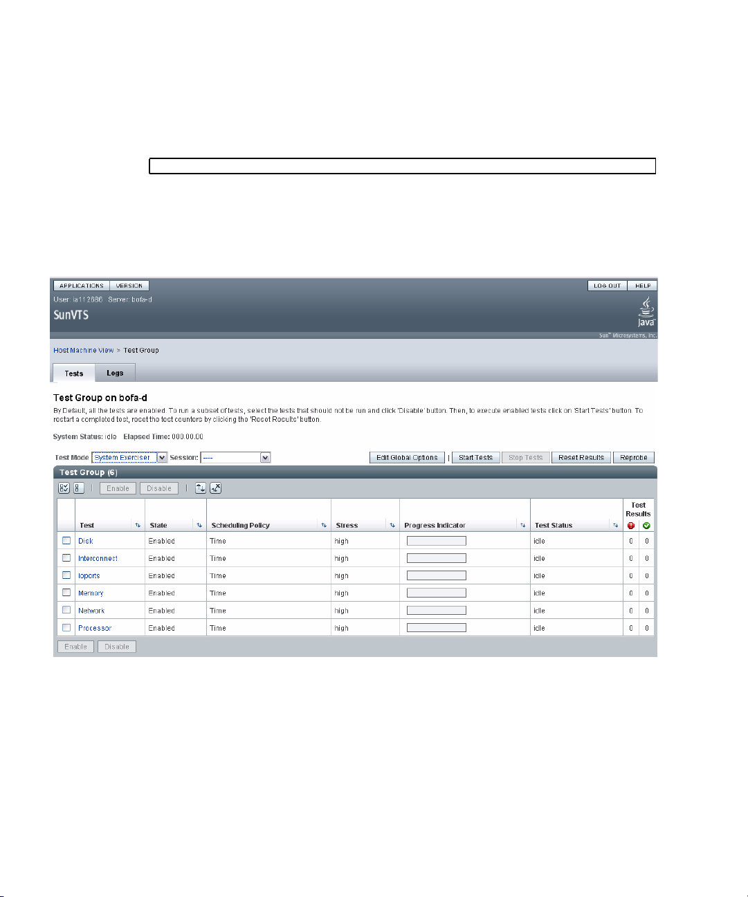
3. Remotely log in to the server as superuser.
4. Start SunVTS software.
# /opt/SUNWvts/bin/sunvts -display display-system:0
FIGURE 2-20 SunVTS BI
Type a command such as rlogin or telnet.
As SunVTS starts, it prompts you to choose between using CLI, BI, or tty
interfaces. A representative SunVTS BI is displayed below (
FIGURE 2-20).
2-52 Sun Blade T6320 Server Module Service Manual • June 2009
Page 79

5. (Optional) Select the test category you want to run.
Certain tests are enabled by default, and you can choose to accept these.
Alternatively, you can enable or disable test categories by clicking the checkbox
next to the test name or test category name. Tests are enabled when checked, and
disabled when not checked.
TABLE 2-10 lists tests that are especially useful to run on this server.
TABLE 2-10 Useful SunVTS Tests to Run on This Server
Category SunVTS Tests FRUs Exercised by Tests
CPU mptest CPU and motherboard
Graphics pfbtest, graphicstest—indirectly:
systest
Processor cmttest, cputest, fputest, iutest,
l1dcachetest, dtlbtest, and
l2sramtest—indirectly: mptest, and
systest
Disk disktest Disks, cables, disk backplane
Environment hsclbtest, cryptotest Crypto engine (CPU), SP <-->, host
Network nettest, netlbtest,xnetlbtest Network interface, network cable, CPU
Memory pmemtest, vmemtest, ramtest DIMMs, motherboard
I/O ports usbtest, iobustest Motherboard, service processor
DIMMs, CPU motherboard
DIMMs, CPU motherboard
communication channels (motherboard)
motherboard
(Host to service processor interface)
6. (Optional) Customize individual tests.
You can customize test categories by right-clicking on the name of the test.
7. Start testing.
Click the Start button that is located at the top left of the SunVTS window. Status
and error messages appear in the test messages area located across the bottom of
the window. You can stop testing at any time by clicking the Stop button.
During testing, SunVTS software logs all status and error messages. To view
these messages, click the Log button or select Log Files from the Reports menu.
This action opens a log window from which you can choose to view the
following logs:
■ Information – Detailed versions of all the status and error messages that
appear in the test messages area.
■ Test Error – Detailed error messages from individual tests.
Chapter 2 Sun Blade T6320 Server Module Diagnostics 2-53
Page 80

■ VTS Kernel Error – Error messages pertaining to SunVTS software itself. Look
here if SunVTS software appears to be acting strangely, especially when it
starts up.
■ Solaris OS Messages (/var/adm/messages) – A file containing messages
generated by the operating system and various applications.
■ Log Files (/var/sunvts/logs) – A directory containing the log files.
2.11 Resetting the Password to the Factory Default
The procedure for resetting the ILOM root password to the factory default
(changeme) requires installation of a jumper on the service processor. This
procedure should be performed by a technician, a service professional, or a system
administrator who services and repairs computer systems. This person should meet
the criteria described in the preface of the Sun Blade T6320 Server Module Service
Manual.
2.11.1 To Reset the Root Password to the Factory Default
1. Remove the server module from the modular system chassis.
Prepare for removal using ILOM or ALOM CMT commands and ensure that the
blue OK to Remove LED is lit, indicating that it is safe to remove the blade.
2. Open the server module and install a standard jumper on the two pins at
location J0600.
3. Close the server module, install it in the modular system chassis, and boot the
server module.
Refer to the Sun Blade T6320 Server Module Installation Guide for instructions.
The ILOM root password is now reset to the factory default (changeme).
4. Change the root password.
Refer to the Sun Blade T6320 Server Module Installation Guide for instructions.
5. Remove the server module from the modular system chassis and remove the
jumper.
As in Step 1, prepare for removal using ILOM or ALOM CMT commands and
ensure that the blue OK to Remove LED is lit, indicating that it is safe to remove
the blade.
2-54 Sun Blade T6320 Server Module Service Manual • June 2009
Page 81

6. Close the server module, install it in the modular system chassis, and boot the
server module.
Refer to the Sun Blade T6320 Server Module Installation Guide for instructions.
Chapter 2 Sun Blade T6320 Server Module Diagnostics 2-55
Page 82

2-56 Sun Blade T6320 Server Module Service Manual • June 2009
Page 83

CHAPTER
3
Replacing Hot-Swappable and HotPluggable Components
This chapter describes how to remove and replace the hot-swappable and hotpluggable field-replaceable units (FRUs) in the Sun Blade T6320 server module.
The following topics are covered:
■ Section 3.1, “Hot-Pluggable Hard Drives” on page 3-1
■ Section 3.2, “Hot-Plugging a Hard Drive” on page 3-1
■ Section 3.3, “Adding PCI ExpressModules” on page 3-5
3.1 Hot-Pluggable Hard Drives
Hot-pluggable devices are those devices that can be removed and installed while the
system is running, but you must perform administrative tasks first. The Sun Blade
T6320 server module hard drives can be hot-swappable (depending on how they are
configured).
For information about a hot-swappable or hot-pluggable PCI ExpressModule (PCI
EM) or network express module (NEM), see the service manual for your modular
system chassis.
3.2 Hot-Plugging a Hard Drive
The hard drives in the Sun Blade T6320 server module are hot-pluggable, but this
capability depends on how the hard drives are configured.
3-1
Page 84

3.2.1 Rules for Hot-Plugging
To safely remove a hard drive, you must:
■ Prevent any applications from accessing the hard drive.
■ Remove the logical software links.
Hard drives cannot be hot-plugged if:
■ The hard drive provides the operating system, and the operating system is not
mirrored on another drive.
■ The hard drive cannot be logically isolated from the online operations of the
server module.
If your drive falls into these conditions, you must shut the system down before you
replace the hard drive. See Section 4.2.2, “Shutting Down the System” on page 4-3.
3.2.2 Removing a Hard Drive
1. Identify the physical location of the hard drive that you want to replace
(
FIGURE 3-2).
2. Type the Solaris OS commands required to stop using the hard drive.
The exact commands required depend on the configuration of your hard drives.
You might need to unmount file systems or perform RAID commands.
One command that you may use to take the drive offline is cfgadm. For more
information see the Solaris cfgadm man page.
3. Verify that the blue Drive Ready to Remove LED is illuminated on the front of
the hard drive.
3-2 Sun Blade T6320 Server Module Service Manual • June 2009
Page 85

FIGURE 3-1 Hard Drive Locations and LEDs
Amber LED
Service Action Required
HDD2
HDD0
Green LED
Drive OK
HDD3
HDD1
Blue LED
Drive Ready to Remove
4. Push the latch release button (FIGURE 3-2).
Caution – The latch is not an ejector. The latch can be damaged if you bend it too
much. Handle the hard drive carefully: the hard drive printed circuit board is not
covered.
5. Grasp the latch and pull the drive out of the drive slot.
Chapter 3 Replacing Hot-Swappable and Hot-Pluggable Components 3-3
Page 86

FIGURE 3-2 Hard Drive Locations, Release Button, and Latch
HDD2
HDD0
HDD3
HDD1
3.2.3 Replacing a Hard Drive or Installing a New Hard Drive
The hard drive is physically addressed to the slot in which it is installed.
Note – If you removed a hard drive, ensure that you install the replacement drive in
the same slot.
1. If necessary, remove the hard drive filler panel.
2. Slide the drive into the bay until it is fully seated (
3-4 Sun Blade T6320 Server Module Service Manual • June 2009
FIGURE 3-2.).
Page 87

3. Close the latch to lock the drive in place.
4. Perform administrative tasks to reconfigure the hard drive.
The procedures that you perform at this point depend on how your data is
configured. You might need to partition the drive, create file systems, load data from
backups, or have data updated from a RAID configuration.
■ You can use the Solaris command cfgadm -al to list all disks in the device tree,
including 'unconfigured' disks.
■ If the disk is not in the list, such as with a newly installed disk, you can use
devfsadm to configure it into the tree. See the devfsadm man page for details.
3.3 Adding PCI ExpressModules
The PCI ExpressModules (PCI EMs) plug into the chassis. To verify installation and
to set up the PCI EMs see:
■ The service manual for your modular system chassis.
■ Sun Integrated Lights Out Manager 2.0 Supplement for Sun Blade T6320 Server
Modules, 820-2546
Chapter 3 Replacing Hot-Swappable and Hot-Pluggable Components 3-5
Page 88

3-6 Sun Blade T6320 Server Module Service Manual • June 2009
Page 89

CHAPTER
4
Replacing Cold-Swappable Components
This chapter describes how to remove and replace field-replaceable units (FRUs) that
must be cold-swapped.
The following topics are covered:
■ Section 4.1, “Safety Information” on page 4-1
■ Section 4.2, “Common Procedures for Parts Replacement” on page 4-3
■ Section 4.3, “Removing and Replacing DIMMs” on page 4-10
■ Section 4.4, “Removing and Replacing the Service Processor” on page 4-15
■ Section 4.5, “Removing and Replacing the Battery on the Service Processor” on
page 4-18
■ Section 4.6, “Replacing or Installing the Sun Blade RAID 5 Expansion Module” on
page 4-20
■ Section 4.7, “Removing and Replacing the Sun Blade G2 RAID 0/1 Expansion
Module” on page 4-25
■ Section 4.8, “Finishing Component Replacement” on page 4-28
4.1 Safety Information
This section describes important safety information you need to know prior to
removing or installing parts in the Sun Blade T6320 server module.
For your protection, observe the following safety precautions when setting up your
equipment:
4-1
Page 90

■ Follow all Sun standard cautions, warnings, and instructions marked on the
equipment and described in Important Safety Information for Sun Hardware Systems,
816-7190.
■ Ensure that the voltage and frequency of your power source match the voltage
and frequency inscribed on the equipment s electrical rating label.
■ Follow the electrostatic discharge safety practices as described in this section.
4.1.1 Safety Symbols
The following symbols might appear in this manual, note their meanings:
Caution – There is a risk of personal injury and equipment damage. To avoid
personal injury and equipment damage, follow the instructions.
Caution – Hot surface. Avoid contact. Surfaces are hot and might cause personal
injury if touched.
Caution – Hazardous voltages are present. To reduce the risk of electric shock and
danger to personal health, follow the instructions.
4.1.2 Electrostatic Discharge Safety
Electrostatic discharge (ESD) sensitive devices, such as the motherboard, hard
drives, and memory cards require special handling.
Caution – The boards and hard drives contain electronic components that are
extremely sensitive to static electricity. Ordinary amounts of static electricity from
clothing or the work environment can destroy components. Do not touch the
components along their connector edges.
4.1.2.1 Using an Antistatic Wrist Strap
Wear an antistatic wrist strap and use an antistatic mat when handling components
such as drive assemblies, boards, or cards. When servicing or removing server
module components, attach an antistatic strap to your wrist and then to a metal area
4-2 Sun Blade T6320 Server Module Service Manual • June 2009
Page 91

on the chassis. Do this after you disconnect the power cords from the server module.
Following this practice equalizes the electrical potentials between you and the server
module.
4.1.2.2 Using an Antistatic Mat
Place ESD-sensitive components such as the motherboard, memory, and other PCB
cards on an antistatic mat.
4.2 Common Procedures for Parts Replacement
Before you can remove and replace internal components, you must perform the
procedures in this section.
4.2.1 Required Tools
You can service the Sun Blade T6320 server module with the following tools:
■ Antistatic wrist strap
■ Antistatic mat
4.2.2 Shutting Down the System
Performing a graceful shutdown ensures that all of your data is saved and that the
system is ready for restart. This section describes procedures for using the ILOM CLI
and the ILOM web interface to shut down the system.
Chapter 4 Replacing Cold-Swappable Components 4-3
Page 92

1. Log in as superuser or equivalent.
TABLE 4-1 Poweroff Command Equivalents
ILOM Web Interface Tabs ILOM CLI
Remote Control,
Remote Power Control,
Select Action
-> stop /sys sc> poweroff -y Use a paper clip to press the
-> stop -script /sys
Depending on the nature of the problem, you might want to view the system
status, the log files, or run diagnostics before you shut down the system. For
more information, refer to:
■ Sun Integrated Lights Out Manager 2.0 Supplement for Sun Blade T6320 Server
Modules, 820-2546. This document describes ILOM information specific to the
UltraSPARC and the Sun Blade T6320 server module. It also provides command
comparisons of the ALOM CMT and ILOM CLI command sets.
■ Appendix D of this service manual also provides some information about ILOM.
2. Notify affected users.
Refer to your Solaris system administration documentation for additional
information.
3. Save any open files and quit all running programs.
Refer to your application documentation for specific information on these
processes.
4. Shut down the Solaris OS using the shutdown (1M)command.
ALOM-CMT
Compatibility Shell Server Module Power Button
power button for a graceful
shutdown.
5. Use either the ILOM web interface, or the ILOM CLI, to finish the shut down
sequence as described in the following sections.
You can also press the power button on the front of the server module to initiate
a graceful shutdown.
4.2.3 Using the ILOM Web Interface to Shut Down the Server Module
1. From the ILOM web interface, select the tabs: Remote Control, Remote Power
Control (
In the Select Action menu, choose a shutdown option.
4-4 Sun Blade T6320 Server Module Service Manual • June 2009
FIGURE 4-1).
Page 93

FIGURE 4-1 Powering Off the Server Module with the ILOM Web Interface
4.2.4 Using the ILOM CLI to Shut Down the Server Module
1. Switch from the system (host) console to the ILOM -> prompt by typing the
#. (Hash-Period) key sequence.
Chapter 4 Replacing Cold-Swappable Components 4-5
Page 94

2. At the ILOM -> prompt, type the set /SYS/PS0
prepare_to_remove_action=true command and type y to confirm.
ILOM CLI, ILOM web interface, and ALOM-CMT command equivalents are
shown in
-> set /SYS/ prepare_to_remove_action=true
Are you sure you want to stop /SYS (y/n)? y
Stopping /SYS
TABLE 4-1.
The blue blade ok2 remove LED is illuminated.
The top white LED is the Locator LED. You can also set the white locator LED to
blink:
-> set /SYS/LOCATE value=fast_blink
Once you have located the server module, you can press the Locator LED to turn
it off.
3. If a cable is connected to the front of the server module, disconnect it.
4-6 Sun Blade T6320 Server Module Service Manual • June 2009
Page 95
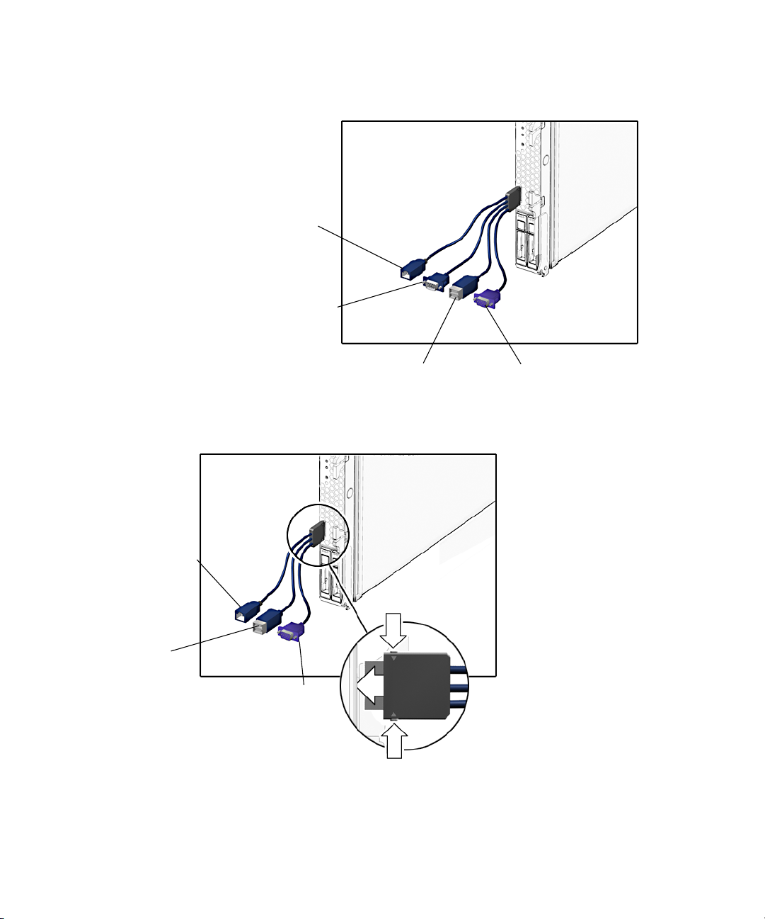
FIGURE 4-2 Disconnecting the Cable Dongle
RJ-45 (Do not use this connector with
the Sun Blade T6320 Server Module)
DB-9 serial, male
(TTYA)
Four connector dongle cable (UCP-4)
RJ-45 serial
USB 2.0
(two connectors)
USB 2.0
(two connectors)
Three connector dongle cable (UCP-3)
VGA 15-pin, female
VGA 15-pin, female
Chapter 4 Replacing Cold-Swappable Components 4-7
Page 96

Caution – The cable dongle is for temporary connections only. The cable dongle has
not been evaluated for electromagnetic compatibility (EMC). The cable dongle or
server module connectors could be damaged by rack doors or other impacts.
Remove the cable dongle during normal system operation.
Note – If you are using the older 4-cable dongle (UCP-4), do not use the RJ-45
connector with the Sun Blade T6320 server module. Use the DB-9 connector for serial
connections.
4. Open the ejector levers (
FIGURE 4-3 Removing the Sun Blade T6320 Server Module From the Chassis
FIGURE 4-3).
5. While pinching the release latches, slowly pull the server module forward
until the slide rails latch.
4-8 Sun Blade T6320 Server Module Service Manual • June 2009
Page 97

Caution – Hold the server module firmly so that you do not drop it. The server
module weighs approximately 16 pounds (7.3 kg).
Caution – Do not stack server modules higher than five units tall. They might fall
and cause damage or injury.
FIGURE 4-4 Stack Five Server Modules or Fewer
6. Set the server module on an antistatic mat.
7. Attach an antistatic wrist strap.
When servicing or removing server module components, attach an antistatic strap to
your wrist and then to a metal area on the chassis.
Chapter 4 Replacing Cold-Swappable Components 4-9
Page 98

FIGURE 4-5 Antistatic Mat and Wrist Strap
8. While pressing the top cover release button, slide the cover toward the rear of
the server module about an inch (2.5 mm).
9. Lift the cover off the chassis.
4.3 Removing and Replacing DIMMs
This section describes how to remove and replace DIMMs.
4.3.1 Removing the DIMMs
LEDs indicate if a DIMM requires replacement.
■ If the system is still powered on and installed in the chassis, see Section 2.2,
“Memory Configuration and Fault Handling” on page 2-7 to determine if a
DIMM requires replacement.
■ If the server module is powered off, you can remove the server module from the
chassis. Pressing the DIMM Locate button illuminates and LED next to the faulty
DIMMs (
Caution – Ensure that you follow antistatic practices as described in Section 4.1.2,
“Electrostatic Discharge Safety” on page 4-2.
4-10 Sun Blade T6320 Server Module Service Manual • June 2009
FIGURE 4-6).
Page 99

1. Perform the procedures described in Section 4.2, “Common Procedures for Parts
Replacement” on page 4-3.
2. Locate the DIMMs that you want to replace (
FIGURE 4-7).
The server module has a DIMM locate button on the motherboard. Press the
DIMM locate button to illuminate the LEDs of the bad DIMMs.
FIGURE 4-6 DIMM Locate Button and DIMM LEDs
You can also use FIGURE 4-7 and TABLE 4-2 to identify the DIMMs that you want to
remove.
Chapter 4 Replacing Cold-Swappable Components 4-11
Page 100

FIGURE 4-7 DIMM Installation Rules
Four DIMMs installed
BR2/CH0/D0
BR3/CH0/D0
BR1/CH0/D0
BR0/CH0/D0
Eight DIMMs installed
BR1/CH1/D0
BR0/CH1/D0
BR2/CH1/D0
BR3/CH1/D0
BR1/CH1/D1
BR1/CH0/D1
BR0/CH1/D1
BR0/CH0/D1
BR2/CH0/D1
BR2/CH1/D1
BR3/CH0/D1
BR3/CH1/D1
Sixteen DIMMs installed
TABLE 4-2 FB-DIMM Configuration
Branch Name Channel Name FRU Name
Motherboard
FB-DIMM
Connector
FB-DIMM
Installation
*
Order
Branch 0 Channel 0 /SYS/MB/CMP0/BR0/CH0/D0 J1001 1 A
/SYS/MB/CMP0/BR0/CH0/D1 J1101 3 B
4-12 Sun Blade T6320 Server Module Service Manual • June 2009
FB-DIMM
\
Pair
 Loading...