

Page 1

External I/O Expansion Unit
for SPARC Enterprise
T5120/T5140/T5220/T5240/T5440 Servers
Installation and Service Manual
Part No. E20767-01
April 2011
Page 2

Copyright ©2007, 2011, Oracle and/orits affiliates.All rightsreserved.
FUJITSU LIMITEDprovided technicalinput andreview on portions of this material.
Oracle and/orits affiliatesand FujitsuLimited eachown orcontrol intellectual propertyrights relatingto products andtechnology describedin this
document, andsuch products,technology andthis documentare protected bycopyright laws,patents, andother intellectualproperty lawsand
international treaties.
This documentand theproduct andtechnology towhich itpertains are distributed underlicenses restrictingtheir use,copying, distribution,and
decompilation. Nopart ofsuch productor technology, orof thisdocument, maybe reproduced in anyform byany meanswithout priorwritten
authorization ofOracle and/orits affiliatesand FujitsuLimited, andtheir applicablelicensors, ifany. The furnishingsof thisdocument toyou doesnot
give youany rightsor licenses,express orimplied, withrespect to the product ortechnology towhich itpertains, andthis documentdoes notcontain or
represent any commitment of any kind on the part of Oracle or Fujitsu Limited, or any affiliateof eitherof them.
This documentand theproduct andtechnology describedin thisdocument mayincorporate third-party intellectual propertycopyrighted byand/or
licensed fromthe suppliersto Oracleand/or itsaffiliates and Fujitsu Limited, including software andfont technology.
Per theterms ofthe GPLor LGPL,a copyof thesource codegoverned bythe GPLor LGPL,as applicable, is available upon request bythe EndUser.Please
contact Oracleand/or itsaffiliates orFujitsu Limited.
This distributionmay includematerials developedby thirdparties.
Parts ofthe product maybe derivedfromBerkeley BSDsystems, licensedfrom theUniversity of California. UNIX isa registered trademarkin theU.S. and
in othercountries, exclusivelylicensed throughX/Open Company, Ltd.
Oracle andJava areregisteredtrademarks ofOracle and/orits affiliates.Fujitsu andthe Fujitsulogo are registered trademarks ofFujitsu Limited.
All SPARC trademarksare usedunder license and are registered trademarks ofSPARC International,Inc. inthe U.S.and other countries.Products bearing
SPARC trademarksare basedupon architectures developed byOracle and/orits affiliates.SPARC64 is atrademark ofSPARC International,Inc., used
under licenseby FujitsuMicroelectronics, Inc. and Fujitsu Limited. Other names may be trademarks of their respectiveowners.
United StatesGovernment Rights- Commercialuse. U.S.Government usersare subject to the standardgovernment userlicense agreementsof Oracle
and/or itsaffiliates andFujitsu Limitedand theapplicable provisions of theFARand itssupplements.
Disclaimer: Theonly warrantiesgranted byOracle andFujitsu Limited,and/or anyaffiliate ofeither ofthem inconnection withthis documentor any
product ortechnology describedherein are thoseexpressly setforth inthe licenseagreement pursuant to which the product ortechnology isprovided.
EXCEPT ASEXPRESSLY SETFORTH IN SUCH AGREEMENT,ORACLE ORFUJITSU LIMITED,AND/OR THEIRAFFILIATESMAKE NO
REPRESENTATIONS OR WARRANTIESOF ANYKIND (EXPRESSOR IMPLIED)REGARDING SUCHPRODUCT ORTECHNOLOGY ORTHIS
DOCUMENT,WHICH AREALL PROVIDEDAS IS,AND ALLEXPRESS ORIMPLIED CONDITIONS,REPRESENTATIONSAND WARRANTIES,
INCLUDING WITHOUTLIMITATION ANY IMPLIED WARRANTY OF MERCHANTABILITY,FITNESS FORA PARTICULAR PURPOSE OR NONINFRINGEMENT,ARE DISCLAIMED,EXCEPT TO THEEXTENT THAT SUCH DISCLAIMERS ARE HELD TOBE LEGALLY INVALID. Unless
otherwise expresslyset forthin suchagreement, to the extent allowed by applicable law,in noevent shallOracle orFujitsu Limited,and/or anyof their
affiliates haveany liabilityto anythird party under any legal theory for any loss of revenuesor profits,loss ofuse ordata, orbusiness interruptions,or for
any indirect,special, incidentalor consequentialdamages, evenif advisedof thepossibility ofsuch damages.
DOCUMENTATION IS PROVIDED “AS IS” AND ALL EXPRESS OR IMPLIED CONDITIONS, REPRESENTATIONS ANDWARRANTIES,
INCLUDING ANYIMPLIED WARRANTY OF MERCHANTABILITY, FITNESSFOR APARTICULAR PURPOSE ORNON-INFRINGEMENT,ARE
DISCLAIMED, EXCEPTTO THEEXTENT THAT SUCHDISCLAIMERS AREHELD TOBE LEGALLY INVALID.
Please
Recycle
Page 3

Copyright ©2007, 2011, Oracle et/ouses sociétésaffiliées. Tous droitsréservés.
FUJITSU LIMITEDa fourniet vérifiédes donnéestechniques decertaines partiesde cecomposant.
Oracle et/ouses sociétésaffiliées etFujitsu Limiteddétiennent etcontrôlent chacunedes droits de propriétéintellectuelle relatifsaux produitset
technologies décritsdans cedocument. Demême, cesproduits, technologieset cedocument sontprotégés par des lois sur le copyright, des brevets,
d’autres loissur lapropriété intellectuelle et des traités internationaux.
Ce document,le produitet lestechnologies afférents sont exclusivementdistribués avecdes licencesqui enrestreignent l’utilisation, lacopie, la
distribution etla décompilation.Aucune partiede ceproduit, deces technologiesou dece documentne peutêtre reproduite sousquelque formeque ce
soit, parquelque moyenque cesoit, sansl’autorisation écritepréalable d’Oracleet/ou sessociétés affiliéeset deFujitsu Limited,et deleurs éventuels
bailleurs delicence. Cedocument, bienqu’il vousait étéfourni, nevous confèreaucun droit et aucunelicence, expressesou tacites,concernant leproduit
ou latechnologie auxquelsil serapporte. Parailleurs, ilne contientni nereprésente aucunengagement, dequelque typeque cesoit, dela partd’Oracle ou
de FujitsuLimited, oudes sociétésaffiliées del’une oul’autre entité.
Ce document,ainsi queles produitset technologiesqu’il décrit,peuvent inclure des droitsde propriétéintellectuelle departies tierces protégéspar
copyright et/oucédés souslicence pardes fournisseursà Oracleet/ou sessociétés affiliéeset FujitsuLimited, ycompris deslogiciels etdes technologies
relatives auxpolices decaractères.
Conformément auxconditions dela licenceGPL ouLGPL, unecopie ducode sourcerégi parla licenceGPL ouLGPL, selonle cas,est disponiblesur
demande parl’Utilisateur final.Veuillez contacter Oracleet/ou sessociétés affiliéesou FujitsuLimited.
Cette distributionpeut comprendre des composantsdéveloppés pardes partiestierces.
Des partiesde ceproduit peuventêtre dérivées des systèmes Berkeley BSD, distribués sous licence par l’Université de Californie. UNIX est une marque
déposée auxÉtats-Unis etdans d’autrespays, distribuéeexclusivement souslicence parX/Open Company, Ltd.
Oracle etJava sontdes marquesdéposées d’OracleCorporation et/oude sessociétés affiliées. Fujitsu etle logoFujitsu sontdes marquesdéposées de
Fujitsu Limited.
Toutes lesmarques SPARCsont utiliséessous licenceet sontdes marquesdéposées deSPARC International, Inc.,aux États-Uniset dansd’autres pays. Les
produits portantla marque SPARCreposent sur des architectures développéespar Oracleet/ou sessociétés affiliées. SPARC64 est une marquede SPARC
International, Inc.,utilisée souslicence parFujitsu Microelectronics, Inc. etFujitsu Limited.Toutautre nom mentionné peut correspondreà desmarques
appartenant àd’autres propriétaires.
United StatesGovernment Rights- Commercialuse. U.S. Government users are subjectto thestandard governmentuser licenseagreements ofOracle
and/or itsaffiliates andFujitsu Limitedand theapplicable provisions of theFARand itssupplements.
Avis denon-responsabilité : lesseules garantiesoctroyées par Oracle et Fujitsu Limited et/ou toute société affiliée del’une oul’autre entitéen rapport
avec cedocument outout produitou toutetechnologie décritsdans lesprésentes correspondent aux garantiesexpressément stipuléesdans lecontrat de
licence régissantle produitou latechnologie fournis.SAUF MENTIONCONTRAIRE EXPRESSÉMENTSTIPULÉE DANSCE CONTRAT,ORACLE OU
FUJITSU LIMITEDET LESSOCIÉTÉS AFFILIÉESÀ L’UNE OU L’AUTRE ENTITÉREJETTENT TOUTEREPRÉSENTATION OU TOUTE GARANTIE,
QUELLE QU’ENSOIT LANATURE(EXPRESSE OUIMPLICITE) CONCERNANTCE PRODUIT, CETTE TECHNOLOGIE OU CE DOCUMENT,
LESQUELS SONTFOURNIS ENL’ÉTAT. EN OUTRE,TOUTES LES CONDITIONS, REPRÉSENTATIONS ET GARANTIESEXPRESSES OUTACITES,Y
COMPRIS NOTAMMENT TOUTEGARANTIE IMPLICITERELATIVEÀ LAQUALITÉ MARCHANDE,À L’APTITUDE À UNEUTILISATION
PARTICULIÈRE OU À L’ABSENCEDE CONTREFAÇON, SONT EXCLUES,DANS LAMESURE AUTORISÉE PAR LA LOI APPLICABLE. Sauf mention
contraire expressément stipulée dansce contrat,dans lamesure autoriséepar laloi applicable,en aucuncas Oracleou FujitsuLimited et/oul’une ou
l’autre deleurs sociétésaffiliées ne sauraient être tenuesresponsables enversune quelconquepartie tierce, sousquelque théoriejuridique quece soit,de
tout manqueà gagnerou deperte deprofit, deproblèmes d’utilisation ou de perte de données, ou d’interruptionsd’activités, oude toutdommage
indirect, spécial,secondaire ou consécutif, même si ces entités ont été préalablement informées d’une telle éventualité.
LA DOCUMENTATIONEST FOURNIE« EN L’ÉTAT » ET TOUTEAUTRE CONDITION,DÉCLARATION ETGARANTIE, EXPRESSEOU TACITE, EST
FORMELLEMENT EXCLUE,DANS LAMESURE AUTORISÉEPAR LA LOIEN VIGUEUR,Y COMPRISNOTAMMENTTOUTE GARANTIE
IMPLICITE RELATIVE À LAQUALITÉ MARCHANDE,À L’APTITUDE ÀUNE UTILISATION PARTICULIÈRE OU ÀL’ABSENCE DE
CONTREFAÇON.
Page 4

Page 5

Contents
Preface xi
1. Overview 1–1
1.1 General Description 1–2
1.1.1 Chassis 1–4
1.1.2 Power Supply Units 1–5
1.1.2.1 AC Power 1–6
1.1.2.2 Fans 1–6
1.1.3 I/O Boats 1–6
1.2 Card Slots 1–8
1.2.1 Carriers 1–9
1.2.2 Link Kit 1–12
1.2.3 Cable Management 1–13
1.3 Carriers 1–16
1.3.1 Carrier Removal and Insertion 1–17
1.3.2 Card Locks 1–19
1.2.1.1 Carrier Slots 1–9
1.2.1.2 Dummy Cards 1–11
1.2.3.1 Minimum Bend Radius for Link Cables 1–15
1.2.3.2 Cable Management Unit 1–15
v
Page 6

1.3.3 Tightening Sequence for Card Locks 1–20
1.3.3.1 Tightening Sequence for Wide Cards 1–21
1.3.3.2 Tightening Sequence for Narrow Cards 1–21
1.3.4 Examples of PCI Card Installation 1–22
1.3.4.1 Using Card Locks With Tall PCI Cards 1–24
1.3.4.2 Using Card Locks With Low and Very Low Height PCI
Cards 1–25
1.3.4.3 Using Card Locks With Unusual PCI Card Shapes 1–26
1.3.5 PCI Card Mounting Problems 1–26
1.3.5.1 Tilted Cards 1–26
1.3.5.2 Hidden Problems 1–28
1.3.6 Carrier Keys 1–32
1.4 External I/O Expansion Unit Configurations 1–33
1.4.1 Single Boat Configuration 1–33
1.4.2 Dual Boat Configuration 1–33
1.5 LEDs 1–34
1.6 System Management 1–36
1.6.1 Maximum Temperatures in the External I/O Expansion Unit 1–36
1.7 Site Preparation 1–38
1.7.1 Physical Requirements 1–38
1.7.2 Electrical Requirements 1–38
1.8 Service Information 1–39
1.9 Electrostatic Discharge Precautions 1–40
2. Installing the External I/O Expansion Unit in a Rack 2–1
2.1 Tools 2–1
2.2 Installing the Mounting Brackets in a Rack 2–2
2.3 Installing the External I/O Expansion Unit in the Rack 2–7
2.4 Installing the Cable Management Unit 2–9
vi External I/O Expansion Unit Installation and Service Manual for SPARC Enterprise T5xxx Servers • April 2011
Page 7

2.5 Installing the AC Cords 2–13
2.6 Installing the Link Kit 2–16
3. Working With PCI Cards 3–1
3.1 Installing a PCI Card 3–1
3.2 Replacing a PCI Card 3–9
3.3 Installing Cables for PCI Cards 3–16
4. Servicing and Replacing Components 4–1
4.1 Service Procedures Task Map 4–2
4.2 Replacing a Power Supply Unit 4–3
4.3 Preparing the Cable Plate for Service 4–5
4.4 Replacing a Carrier 4–7
4.5 Replacing a Link Cable 4–10
4.6 Replacing a Link Card in the Host Server 4–10
4.7 Replacing a Link Card in an I/O Boat 4–11
4.8 Installing a Second I/O Boat 4–13
4.9 Replacing an I/O Boat 4–16
4.9.1 Replacing a Boat in a Single Boat Configuration 4–16
4.9.2 Replacing a Boat in a Dual Boat Configuration 4–19
4.10 Replacing the External I/O Expansion Unit Chassis 4–21
4.10.1 Locating the New System Serial Number Label 4–22
4.10.2 Preparing the External I/O Expansion Unit 4–22
4.10.3 Moving the Bezel to the New Chassis 4–24
4.10.4 Installing the External I/O Expansion Unit in the Rack 4–28
A. Specifications A–1
A.1 Physical Specifications A–2
A.2 Clearance for Service Access A–2
A.3 Environmental Specifications A–3
Contents vii
Page 8

A.4 Power Source Requirements A–4
A.5 Acoustic Noise Emissions A–4
A.6 Agency Compliance Specifications A–5
B. External I/O Expansion Unit LED Status Indicators B–1
B.1 LED Locations B–2
B.2 LED States B–4
C. Using the ILOM CLI C–1
C.1 Using the CLI C–1
C.1.1 Starting the CLI C–2
C.1.2 Listing Valid Targets In a Namespace C–2
C.1.3 Listing Targets Below a Namespace C–2
C.1.4 Displaying Information About a Target or FRU C–2
C.1.5 Exiting the CLI C–3
C.2 Examples of CLI Commands for an I/O Box C–3
D. Troubleshooting with ILOM Diagnostic Messages D–1
D.1 ILOM Messages D–2
D.1.1 Types of ILOM Messages for External I/O Expansion Unit D–2
D.1.2 Terms Used in ILOM Messages for External I/O Expansion Unit
D–2
D.2 Examples of Messages D–3
D.2.1 When Service Is Required D–3
D.2.2 When Service Is Not Required D–4
D.3 Clearing Ext FRU and Ext Sensor Messages D–4
D.4 Ext FRU Messages D–5
D.5 Ext info Messages D–6
D.6 Ext sensor Messages D–7
D.6.1 I2C_A Bus and I2C_B Bus D–10
viii External I/O Expansion Unit Installation and Service Manual for SPARC Enterprise T5xxx Servers • April 2011
Page 9

D.6.1.1 Causes D–10
D.6.1.2 Power Supply Fault D–10
D.6.1.3 Clearing a Chassis or Boat Fault D–11
D.6.2 Main I2C Bus D–11
D.6.2.1 Causes D–11
D.6.2.2 Clearing a Power Supply Fault D–11
D.6.2.3 Clearing Other Faults D–12
D.6.3 Platform I2C Bus D–12
D.6.3.1 Causes D–12
D.6.3.2 Resolution D–12
D.6.4 Management Bus Link Down D–13
D.6.4.1 Causes D–13
D.6.4.2 Resolution D–13
D.6.5 Management Bus Link Fail D–13
D.6.5.1 Causes D–13
D.6.5.2 Resolution D–14
D.6.6 Interrupt Signal Failures D–14
D.6.6.1 Causes D–14
D.6.6.2 Resolution D–14
D.6.7 Two Boats Report They Are in the Same Location in the Same
External I/O Expansion Unit D–15
D.6.7.1 Cause D–15
D.6.7.2 Resolution D–15
D.6.8 Boat Not Monitored D–15
D.6.8.1 Cause D–16
D.6.8.2 Resolution D–16
D.6.9 I2C Bus Taken by Second System D–16
D.6.9.1 Cause D–16
D.6.9.2 Resolution D–17
Contents ix
Page 10

D.6.10 Boat Presence Signal Failure D–17
D.6.10.1 Cause D–17
D.6.10.2 Resolution D–17
D.6.11 Cannot Determine Boat Location D–17
D.6.11.1 Cause D–17
D.6.11.2 Resolution D–17
D.6.12 Link Card Operating in Wrong Mode D–18
D.6.12.1 Cause D–18
D.6.12.2 Resolution D–18
D.6.13 Can’t Read ManR FRUID Data D–18
D.6.13.1 Cause D–18
D.6.13.2 Resolution D–18
D.6.14 Fan Controller Reset D–19
D.6.14.1 Cause D–19
D.6.14.2 Resolution D–19
D.6.15 Fan Controller Timeout D–19
D.6.15.1 Cause D–19
D.6.15.2 Resolution D–19
D.6.16 Bridge Controller Reset D–19
D.6.17 Bridge Controller Timeout D–20
E. Troubleshooting Hardware Problems E–1
E.1 Troubleshooting the External I/O Expansion Unit E–1
Index Index–1
x External I/O Expansion Unit Installation and Service Manual for SPARC Enterprise T5xxx Servers • April 2011
Page 11

Preface
This manual provides procedures for installing, using, and maintaining the External
I/O Expansion Unit on SPARC Enterprise T5120, T5140, T5220, T5240, and T5440
servers.
This document is written for technicians, system administrators, authorized service
providers, and users who have advanced experience troubleshooting and replacing
hardware.
Note – In programs and manuals, External I/O Expansion Unit might be
abbreviated to I/O Box.
This chapter includes the following sections
■ “External I/O Expansion Unit Documents” on page xi
■ “Text Conventions” on page xii
■ “Notes on Safety” on page xiii
■ “Documentation Feedback” on page xiii
External I/O Expansion Unit Documents
All documents for your External I/O Expansion Unit are available online at the
following locations:
■ External I/O Expansion Unit hardware documents:
http://download.oracle.com/docs/cd/E19322-01/index.html
xi
Page 12

■ Sun Oracle software-related manuals (Oracle Solaris OS, and so on):
http://www.oracle.com/technetwork/documentation/index.html
Book Title
External I/O Expansion Unit Installation and Service Manual
External I/O Expansion Unit Product Notes
External I/O Expansion Unit Safety and Compliance Guide
Text Conventions
This manual uses the following fonts and symbols to express specific types of
information.
Fonts/symbols Meaning Example
AaBbCc123 What you type, when contrasted
with on-screen computer output.
This font represents the example of
command input in the frame.
AaBbCc123 The names of commands, files, and
directories; on-screen computer
output.
This font represents the example of
command input in the frame.
Italic Indicates the name of a reference
manual
" " Indicates names of chapters,
sections, items, buttons, or menus
XSCF> adduser jsmith
XSCF> showuser -P
User Name: jsmith
Privileges: useradm
auditadm
See the SPARC Enterprise
M3000/M4000/M5000/M8000/M90
00 Servers XSCF User’s Guide.
See Chapter 2, "System Features."
xii External I/O Expansion Unit Installation and Service Manual for SPARC Enterprise T5xxx Servers • April 2011
Page 13

Notes on Safety
Read the following documents thoroughly before using or handling any External I/O
Expansion Unit.
■ External I/O Expansion Unit Safety and Compliance Guide.
■ SPARC Enterprise M3000/M4000/M5000/M8000/M9000 Servers Important Legal and
Safety Information
Documentation Feedback
If you have any comments or requests regarding this document, go to the following
web site.
http://www.oraclesurveys.com/se.ashx?s=25113745587BE578
Preface xiii
Page 14

xiv External I/O Expansion Unit Installation and Service Manual for SPARC Enterprise T5xxx Servers • April 2011
Page 15

CHAPTER
1
Overview
The External I/O Expansion Unit provides a host server with additional slots for PCI
cards.
■ The single I/O boat configuration provides six slots for I/O cards.
■ The optional two I/O boat configuration (FIGURE 1-1) provides twelve slots.
Note – The External I/O Expansion Unit might be abbreviated to I/O Box in
programs and manuals.
This chapter contains the following topics:
■ Section 1.1, “General Description” on page 1-2
■ Section 1.2, “Card Slots” on page 1-8
■ Section 1.3, “Carriers” on page 1-16
■ Section 1.4, “External I/O Expansion Unit Configurations” on page 1-33
■ Section 1.5, “LEDs” on page 1-34
■ Section 1.6, “System Management” on page 1-36
■ Section 1.7, “Site Preparation” on page 1-38
■ Section 1.8, “Service Information” on page 1-39
■ Section 1.9, “Electrostatic Discharge Precautions” on page 1-40
1-1
Page 16

FIGURE 1-1 External I/O Expansion Unit, Front and Rear Views
1
2
Figure Legend
Front view
1
2 Rear view
1.1 General Description
FIGURE 1-2 shows the major units for the External I/O Expansion Unit, which are
described separately in this chapter.
Note – All slot numbers run from left to right, regardless of whether you are
viewing the front or the back of the External I/O Expansion Unit. At the front of the
External I/O Expansion Unit, the power supplies are numbered from left to right.
I/O boats at the rear of the External I/O Expansion Unit are also numbered from left
to right.
1-2 External I/O Expansion Unit Installation and Service Manual for SPARC Enterprise T5xxx Servers • April 2011
Page 17

FIGURE 1-2 Major Units for the External I/O Expansion Unit, Top View
1
2
3
4
9
6
5
7
8
Chassis
1
2 Power Supply Unit 1 7 Internal AC cable
6
I/O boat 1
3 Power Supply Unit 0 8 Cable management unit (one of two types is included)
4 Centerplane 9 Link kit
I/O boat 0
5
Chapter 1 Overview 1-3
Page 18

1.1.1 Chassis
The External I/O Expansion Unit chassis includes the centerplane (item 4 in
FIGURE 1-2) and two non-removable internal AC cables (item 7 in FIGURE 1-2).
There are no serviceable components inside the chassis. If the centerplane or the
internal AC cables are damaged, the chassis must be replaced.
Note – A replacement chassis does not include power supply units (PSUs) or I/O
boats. Transfer the PSUs and I/O boats from the damaged chassis to the replacement
chassis.
Each internal AC cable supplies only one PSU. To ensure redundant power, use the
two AC cords supplied with the External I/O Expansion Unit to connect the internal
AC cables to separate AC sources.
Caution – Do not connect the internal AC cables directly to a power strip. Use the
the AC power cords supplied with the External I/O Expansion Unit to connect the
internal AC cables to electrical power.
Caution – Do not substitute other AC power cords for the AC power cords supplied
with the External I/O Expansion Unit. The substitute AC power cords might not
have the same power rating.
1-4 External I/O Expansion Unit Installation and Service Manual for SPARC Enterprise T5xxx Servers • April 2011
Page 19

1.1.2 Power Supply Units
The External I/O Expansion Unit has two power supply units (PSUs) for
redundancy. See
Each PSU includes an integral fan.
FIGURE 1-3 Power Supply Unit
FIGURE 1-3.
7
8
1
6
5
Figure Legend
1 PSU 5 Fan
2 Handle locking screw 6 Caution labels
3 Handle 7 PSU slot 0
4 AC switch 8 PSU slot 1
4
3
Chapter 1 Overview 1-5
2
Page 20

1.1.2.1 AC Power
The PSU slots are powered through internal AC cables that extend out of the rear of
the chassis (
FIGURE 1-2).
The PSUs do not share AC current. Connect both internal AC cables to AC power.
The internal AC cable for a PSU is the cable terminating nearest that PSU slot.
The PSUs should be connected to two independent external AC power sources so
that service will not be interrupted if one AC power source fails.
1.1.2.2 Fans
A fan is located in the front of each PSU. If one fan fails, the remaining fan supplies
enough air to cool two I/O boats.
Note – The fan might turn on when you insert a PSU into the External I/O
Expansion Unit. This is normal behavior if you are installing a second PSU while the
first PSU is powered on. The fan receives DC power through the centerplane.
1.1.3 I/O Boats
The External I/O Expansion Unit can contain up to two I/O boats (FIGURE 1-4).
Note – The maximum number of I/O boats that can be attached to a server can vary
according to the server model. See TABLE 1-1.
TABLE 1-1 Number of I/O Boats Per Server
Server Model Maximum Number of I/O Boats Supported
SPARC Enterprise T5120 Server 1
SPARC Enterprise T5140 Server 2
SPARC Enterprise T5220 Server 2 (Maximum of 1 I/O boat per processor)
SPARC Enterprise T5240 Server 2 (Maximum of 1 I/O boat per processor)
SPARC Enterprise T5440 Server 4 (Maximum of 1 I/O boat per processor)
1-6 External I/O Expansion Unit Installation and Service Manual for SPARC Enterprise T5xxx Servers • April 2011
Page 21

FIGURE 1-4 I/O Boat
1
5
2
3
4
Figure Legend
1 I/O boat 5 Boat slot 0
2 Captive screws 6 Boat slot 1
3 Link card carrier (slot 0) 7 Caution labels
4 PCI card carriers (slots 1-6)
7
The PCI Express I/O boat accepts PCI Express cards up to x8 lanes wide.
6
Chapter 1 Overview 1-7
Page 22

FIGURE 1-5 Logical Layout of I/O Boats
Note – A switch is a device that connects multiple busses to a single bus.
In the I/O boat, all PCI card data passes through the link card.
When you run system diagnostics, the switches are displayed in the output of
OpenBoot PROM probing. However, the link cards themselves never appear during
OpenBoot PROM probing.
1.2 Card Slots
The card slots have the following characteristics:
■ An I/O boat has seven card slots. Slot numbers 0 through 6 are counted from left
to right.
■ Slot 0 is reserved for the link card. Slot 0 is the first slot in the left side of the I/O
boat. For information about link cards, see Section 1.2.2, “Link Kit” on page 1-12.
1-8 External I/O Expansion Unit Installation and Service Manual for SPARC Enterprise T5xxx Servers • April 2011
Page 23

■ Slots 1-6 are for PCI cards. (PCI cards are sometimes known as host adapters or
host bus adapters.)
■ PCI card slots are not hot-pluggable.
■ The PCI Express I/O boat supports up to x8 card sockets. PCI Express x16 cards
are not supported in the PCI Express I/O boat.
Note – Graphics cards are not supported.
Caution – Do not insert a x16 PCI Express card in an I/O boat. The x16 card
connector is too large for the x8 card socket and will damage the socket.
1.2.1 Carriers
All PCI cards in the External I/O Expansion Unit are mounted on carriers
(
FIGURE 1-25). Carriers control RFI emissions and maintain the proper flow of air
through the External I/O Expansion Unit.
The front of each carrier is labelled with its slot number (PCIE 1, and so forth).
Note – Slot 0 is reserved for the link card. This slot is marked LINK 0.
Carriers are physically keyed to fit only specific slot numbers. The keys can be
adjusted for other slots as needed.
New carriers include dummy cards. The dummy cards help the carriers to stay in
place and to control the passage of air through the I/O boat. For information about
dummy cards, see Section 1.2.1.2, “Dummy Cards” on page 1-11.
1.2.1.1 Carrier Slots
There are seven carriers in each I/O boat (FIGURE 1-6). Carriers can be adjusted to fit
various sizes and shapes of PCI cards. Link cards use the same type of carrier.
■ Carrier slot 0 is always used for the link card.
■ Carrier slots 1 through 6 are used for PCI cards.
Chapter 1 Overview 1-9
Page 24

FIGURE 1-6 PCI Carrier
Figure Legend
1 Carrier handle
2 Carrier locking screw
1-10 External I/O Expansion Unit Installation and Service Manual for SPARC Enterprise T5xxx Servers • April 2011
Page 25

1.2.1.2 Dummy Cards
New carriers are shipped with dummy cards (FIGURE 1-7).
FIGURE 1-7 Dummy Card
The service labels (not shown in FIGURE 1-7) on the dummy card include simplified
instructions for removing and installing PCI cards.
Note – Be certain that the dummy cards are fully seated. This action minimizes the
vibration of unused carriers in the I/O boat slots.
PCI-E
Chapter 1 Overview 1-11
Page 26

1.2.2 Link Kit
One link kit (FIGURE 1-8) is required for each I/O boat.
A link kit includes two link cards. One link card goes into the host server. The other
link card goes into the I/O boat. The link cards are physically identical.
A low-profile bracket is included so a link card can be used in a low-profile I/O card
slot.
FIGURE 1-8 Link Kit
Slot 0 in each I/O boat is the dedicated link card slot. Use slot 0 only for the link
card.
1-12 External I/O Expansion Unit Installation and Service Manual for SPARC Enterprise T5xxx Servers • April 2011
Page 27

1.2.3 Cable Management
A cable management unit attaches to the rear of the system rack. There are two types
of cable management units.
■ Some racks allow the routing of cables along both sides of the rack. The type A
cable plate (
of the rack.
■ Some racks allow routing of cables only along the right side of the rack. The type
B cable plate (
rack.
FIGURE 1-9 Cable Management Unit (Type A) for Routing Cables to Both Sides of the
FIGURE 1-9) supports cable routing along both the left and right sides
FIGURE 1-10) is optimized for cable routing along the right side of the
Rack
3
2
1
Figure Legend
1 Type A cable plate
2 Support brackets
3 Cable plate locking screws
3
2
Chapter 1 Overview 1-13
Page 28

FIGURE 1-10 Cable Management Unit (Type B) for Routing Cables Only to the Right Side of
a Rack
3
2
1
3
2
Figure Legend
1 Type B cable plate
2 Support brackets
3 Cable plate locking screws
Note – If the PSU1 power cable does not reach the rack power distribution unit,
route the cable on the left side of the rack.
1-14 External I/O Expansion Unit Installation and Service Manual for SPARC Enterprise T5xxx Servers • April 2011
Page 29

1.2.3.1 Minimum Bend Radius for Link Cables
The link cables might be damaged if they are coiled too tightly. The minimum bend
radius for the link cable is 1.85 in. (47 mm).
Caution – Coiling the link cables with a smaller bend radius than listed above will
break the cables.
1.2.3.2 Cable Management Unit
The cable management unit contains two support brackets and a cable plate.
The support brackets attach with screws to the rear of the system rack. The cable
plate rests on the support brackets.
The cable plate has two positions (
■ In the normal position, the cable plate rests on the support brackets.
■ In the raised position, the cable plate rests slightly above the support brackets.
FIGURE 1-11).
This position provides clearance for you to remove and replace an I/O boat.
FIGURE 1-11 Cable Plate (Side Views of Normal and Service Positions)
2
1
3
Figure Legend
1 Cable plate in the normal position (lowered)
2 Cable plate in the service position (raised)
3 Cable plate locking screw
Chapter 1 Overview 1-15
Page 30

1.3 Carriers
In the I/O boat, all PCI cards are mounted on carriers. When you insert the carrier
and card into the boat and push the carrier handle into the closed position, the
carrier mechanism automatically seats the PCI card.
FIGURE 1-12 shows a carrier with an attached PCI card.
Note – The service life of a carrier is at least 100 PCI card insertions. To avoid
premature failure of the carrier, do not repeatedly open and close the carrier more
than is necessary to familiarize yourself with its operation.
FIGURE 1-12 Carrier
1
2
3
Figure Legend
1 PCI card
2 Carrier
3 Carrier handle in unlocked position
FIGURE 1-13 shows the details of a typical carrier.
1-16 External I/O Expansion Unit Installation and Service Manual for SPARC Enterprise T5xxx Servers • April 2011
Page 31

FIGURE 1-13 Carrier Features
2
3
1
5
6
4
5
5
Figure Legend
1 Carrier main body (metal) 4 Carrier handle
2 Carrier plate (plastic) 5 Card locks (see Section 1.3.2, “Card Locks” on page 1-19)
3 Carrier slot keyholes 6 Turnaround area for card lock
1.3.1 Carrier Removal and Insertion
A carrier operates by raising or lowering a PCI card into or out of a card socket. The
vertical movement is approximately 0.4 in. (10 mm).
A small metal latch (item 3 in
latch locks the carrier handle in the extended position. This action prevents the
carrier plate and PCI card from falling and damaging the PCI slot connector as you
pull the carrier unit out of the carrier slot.
FIGURE 1-14) is located at the front of the carrier. The
Chapter 1 Overview 1-17
Page 32
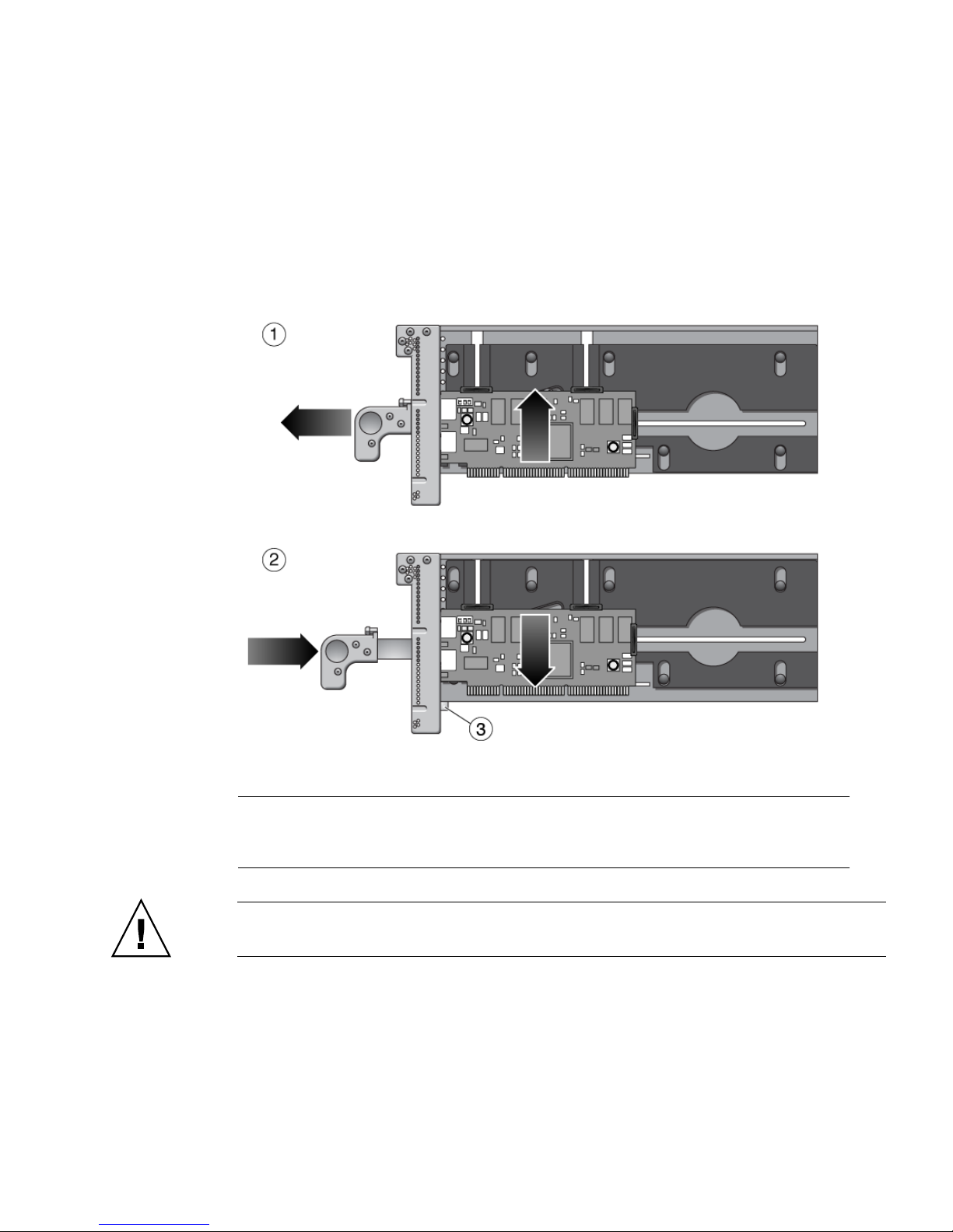
After the carrier is out of the I/O boat, you can unlock the carrier handle by pushing
in the metal latch while pushing the carrier handle into its closed position. Note that
the closed position provides more vertical clearance for a PCI card when you install
or remove the PCI card.
When you insert the carrier into the I/O boat, the latch automatically unlocks itself.
FIGURE 1-14 Carriers
Figure Legend
1 Pull carrier handle to raise PCI card out of PCI slot socket
2 Push carrier handle and latch (3) to lower PCI card into socket
3 Latch
Caution – All carriers must contain either a PCI card or a dummy card to avoid loss
of cooling air.
1-18 External I/O Expansion Unit Installation and Service Manual for SPARC Enterprise T5xxx Servers • April 2011
Page 33

1.3.2 Card Locks
A PCI card is attached to the carrier with screw-mounted locks or retainers
(
FIGURE 1-15). Card locks hold a PCI card to its carrier and prevent the PCI card from
shifting or tilting. The PCI card must be securely mounted in order for the carrier to
correctly seat the PCI card in the card socket in the I/O boat.
FIGURE 1-15 Card Locks
1
2
Figure Legend
1 Type A (Square). There are three of these.
2 Type B (S-shaped)
3 Type C (Small)
3
Chapter 1 Overview 1-19
Page 34

There are three types of locks:
■ Type A is a square-shaped lock. Three of these are supplied with each carrier.
■ Type B is an oblong lock that has an S-shaped profile. It provides a longer
extension (0.75 in., 19 mm) than type A. Type B can be used as a top or side
mount, wherever a longer reach is needed. One of this type is included with each
carrier.
■ Type C is a small quarter-round lock. It can support the bottom edge of a wide PCI
card, but only when the lock is at the far right side of its slot (the side farthest
from the front of the carrier). For a narrow width card, use this lock only to
support the side of the card. Do not use this lock to support the bottom edge of a
narrow width card because the lock might interfere with the card socket in the I/O
boat. This lock fits only the bottom slot on the carrier. One of this type is supplied
with each carrier.
One function of the locks is to secure the PCI card to the carrier. Another is to apply
a downward force to the top of the card to seat the card in the card socket when the
carrier is inserted into the I/O boat. In addition, the locks help prevent the card from
tilting so that card edge pins line up properly with the pins in the socket.
Because PCI card types are available in various sizes and shapes, you should choose
a combination of card locks that is best suited to the size and shape of the PCI card.
1.3.3 Tightening Sequence for Card Locks
To fasten a PCI card to a carrier so that the card will seat reliably, tighten the card
locks in the sequence shown in
PCI card shapes and sizes can vary, so use the following instructions as suggestions,
not as strict requirements.
■ If the PCI card is wide, use the tightening sequence shown in FIGURE 1-16. A wide
card is one that can rest on the type C card lock (item 1 in
card lock is in its extreme right position.
■ If the PCI card is narrow, use the tightening sequence shown in FIGURE 1-17.A
narrow card is one that is too short to rest on the type C card lock when the card
lock is in its extreme right position.
Caution – If you move the type C card lock out of the extreme right position while
the plastic part of the card lock is facing down, the PCI card will not seat properly,
and the bottom of the card lock can damage the PCI card socket in the I/O boat. If
you move the type C card lock to the left at any time, always rotate the card lock so
that the plastic part faces either left or right.
FIGURE 1-16 or FIGURE 1-17.
FIGURE 1-16) when the
1-20 External I/O Expansion Unit Installation and Service Manual for SPARC Enterprise T5xxx Servers • April 2011
Page 35
1.3.3.1 Tightening Sequence for Wide Cards
FIGURE 1-16 Card Lock Sequence for Wide Cards
2 3
1
● Rest the bottom edge of the PCI card on the type C card lock (number 1 in
FIGURE 1-16) to ensure that the bottom of the PCI card is perfectly horizontal,
then tighten the remaining card locks in the sequence shown.
1.3.3.2 Tightening Sequence for Narrow Cards
4
FIGURE 1-17 Card Lock Sequence for Narrow Cards
1
4
2
3
● Tighten the upper left card lock (number 1 in FIGURE 1-17), while ensuring that
the card is perfectly horizontal. Then tighten the remaining card locks in the
sequence shown, as applicable.
Chapter 1 Overview 1-21
Page 36

1.3.4 Examples of PCI Card Installation
FIGURE 1-15 shows the locks for a typical PCI card.
However, cards can be much wider or narrower, or taller or shorter.
FIGURE 1-19, and FIGURE 1-20 show how cards can vary in height, width, and shape.
FIGURE 1-18,
Note – The lock arrangements shown in these figures are suggestions and are not
intended as requirements.
When installing a card, it might be necessary to swap locks from slot to slot in order
to find the best way to secure a PCI card to its carrier. Use
TABLE 1-2 to select locks
that are best suited to your PCI card.
TABLE 1-2 Card and Lock Styles
Suggested Lock Type
PCI Card Shape Top Lock/Card Height Side Lock/Card Width Bottom Lock Example
Wide Type A (x2) Type A
12 in. (304 mm)
maximum card width
Average width Type A (x2) Type A
5.75 in. (146 mm)
minimum card width
Type B
5.0 in. (127 mm)
minimum card width
Type C
Type C
*
FIGURE 1-18
(item 1)
†
FIGURE 1-18
(item 2)
Narrow width Type A (1 or 2) Type A
5.75 in. (146 mm)
FIGURE 1-18
(item 3)
minimum card width
Type B
5.0 in. (127 mm)
minimum card width
Type C
3.0 in. (76 mm)
minimum card width
Very narrow width Type A (1 or 2) Type B
5.0 in. (127 mm)
FIGURE 1-18
(item 4)
minimum card width
Type C
3.0 in. (76 mm)
minimum card width
Tall Type A Type A or B Type C
‡
FIGURE 1-18
(All)
1-22 External I/O Expansion Unit Installation and Service Manual for SPARC Enterprise T5xxx Servers • April 2011
Page 37

TABLE 1-2
PCI Card Shape Top Lock/Card Height Side Lock/Card Width Bottom Lock Example
Card and Lock Styles (Continued)
Suggested Lock Type
Low height Type A
2.0 in. (51mm)
minimum card height
or
Type B
1.25 in. (31mm)
minimum card height
Type A
5.75 in. (146 mm)
minimum card width
Type B
5.0 in. (127 mm)
minimum card width
Type C
3.0 in. (76 mm)
minimum card width
Very low height Type A
2.0 in. (51mm)
minimum card height
or
Type B
1.25 in. (31mm)
minimum card height
Type A
5.75 in. (146 mm)
minimum card width
Type B
5.0 in. (127 mm)
minimum card width
Type C
3.0 in. (76 mm)
minimum card width
Very low height
and narrow width
Type B
1.25 in. (31mm)
minimum card height
Type C
3.0 in. (76 mm)
minimum card width
Irregular shape As needed As needed As needed
FIGURE 1-19
(item 1)
FIGURE 1-19
(item 2)
FIGURE 1-20
(item 1)
**
FIGURE 1-20
(item 2)
* Do not use the type C lock to support the bottom of a card if the lock will be in a location that causes the lock to interfere with the PCI
card connector in the I/O boat.
† Do not use the type C lock to support the bottom of a card if the lock will be in a location that causes the lock to interfere with the PCI
card connector in the I/O boat.
‡ Do not use the type C lock to support the bottom of a card if the lock will be in a location that causes the lock to interfere with the PCI
card connector in the I/O boat.
** Do not use the type C lock to support the bottom of a card if the lock will be in a location that causes the lock to interfere with the PCI
card connector in the I/O boat.
Chapter 1 Overview 1-23
Page 38

1.3.4.1 Using Card Locks With Tall PCI Cards
FIGURE 1-18 Lock Arrangements for Wide and Narrow PCI cards
1
2
3
4
Figure Legend
1 Tall and wide card 2 type A on top, 1 type A on right, 1 type C on bottom of the PCI card
2 Tall and average width card 2 type A on top, 1 type A on right, 1 type C on bottom of the PCI card
3 Tall and narrow card 1 type A on top, 1 type A on right, 1 type C on lower right side of the PCI card
4 Tall and very narrow card 1 type A on top, 1 type B on right, 1 type C on lower right side of the PCI card
1-24 External I/O Expansion Unit Installation and Service Manual for SPARC Enterprise T5xxx Servers • April 2011
Page 39

1.3.4.2 Using Card Locks With Low and Very Low Height PCI Cards
FIGURE 1-19 Lock Arrangements for Low and Very Low Height PCI cards
1
2
Figure Legend
1 Low height card 2 type A on top, 1 type A on right side, 1 type C on lower right side of the PCI card
2 Very low height card 1 type B on top, 1 type A on right edge, 1 type C on lower right side of the PCI card
Chapter 1 Overview 1-25
Page 40

1.3.4.3 Using Card Locks With Unusual PCI Card Shapes
FIGURE 1-20 Lock Arrangements for Unusually-Shaped Cards
1
2
Figure Legend
1 Very low height and narrow width card 1 type B on top, 1 type C on right side of the PCI card
2 Irregularly-shaped card 1 type A and 1 type B on top, 1 type A on right side, 1 type C on lower right
side of the PCI card
1.3.5 PCI Card Mounting Problems
1.3.5.1 Tilted Cards
There are two common problems that involve PCI cards that turn at an angle when
mounted in PCI carriers.
■ The most common problem is that a PCI card can slip and tilt during seating when
you do not apply enough pressure on a PCI carrier card lock when mounting the
card on the carrier.
■ A less common problem is that the bracket of a PCI card will bend when you
apply too much pressure on a PCI carrier card lock when mounting the card on a
carrier.
1-26 External I/O Expansion Unit Installation and Service Manual for SPARC Enterprise T5xxx Servers • April 2011
Page 41

FIGURE 1-21 Excessive Force on a Lock Can Bend or Break the PCI Card
Figure Legend
1 Correct
2 Incorrect
Here are some rules to avoid the tilting of PCI cards:
1. You must have at least one lock on top of the card. If the top of the card is too low
to accept a lock, the card cannot be used.
2. Find a lock to fit the top of the card and provide side support to prevent the card
from tilting. A tilted card (
FIGURE 1-21) will not seat properly.
3. Support of the bottom of the card is not a major priority because the carrier plate
itself provides some support for the bottom of the card.
4. Use only enough pressure to hold the lock against the PCI card. The bottom of the
PCI card should stay parallel with the bottom of the carrier.
Chapter 1 Overview 1-27
Page 42
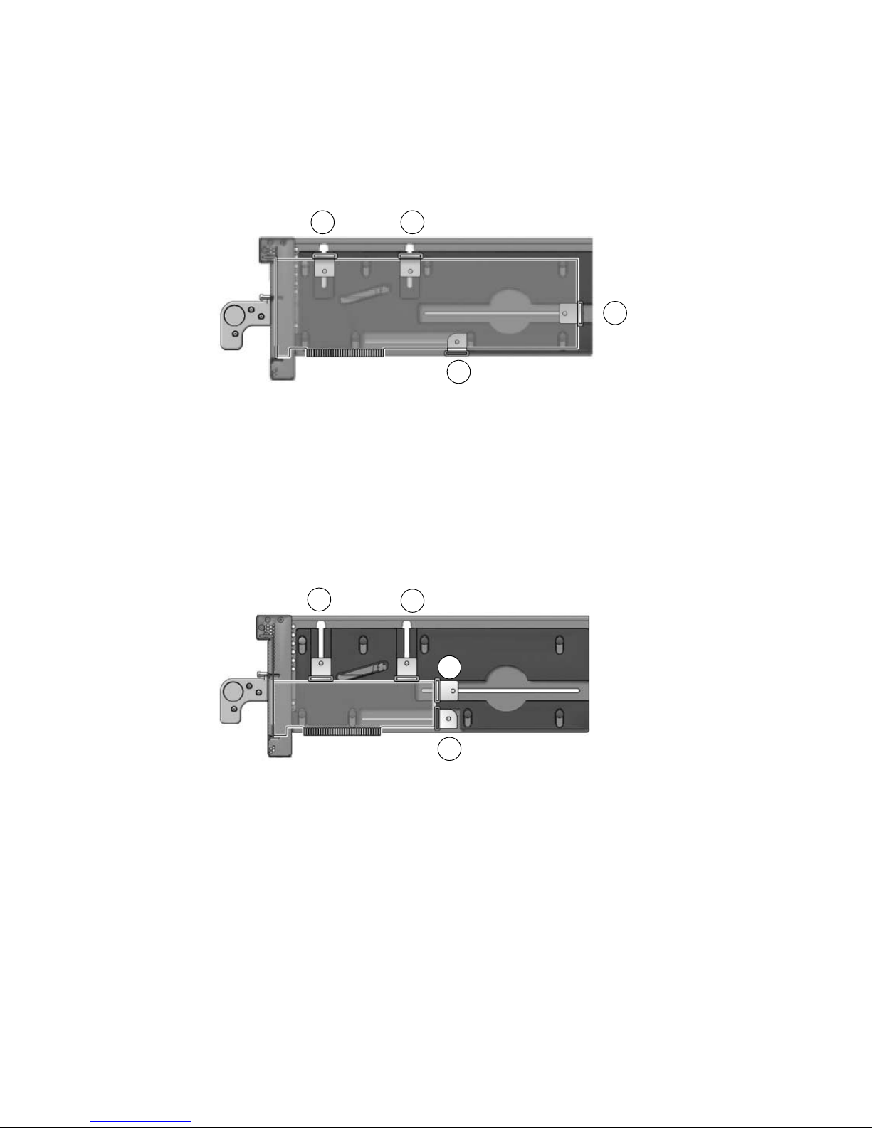
1.3.5.2 Hidden Problems
The following features are located inside the front housing of the carrier. Because
they are difficult to see, they can complicate the mounting of cards on carriers.
■ Card alignment post (FIGURE 1-22 and FIGURE 1-23)
■ Card alignment tab (FIGURE 1-22)
■ Internal RFI gasket (FIGURE 1-24)
Alignment Post and Alignment Tab
The card alignment post and the card alignment tab help to keep the front of the PCI
card in the correct vertical orientation, with support from properly-installed card
locks.
FIGURE 1-22 Card Alignment Post and Card Alignment Tab
1
Figure Legend
1 Card alignment post
2 Card alignment tab
1-28 External I/O Expansion Unit Installation and Service Manual for SPARC Enterprise T5xxx Servers • April 2011
2
Page 43

The post fits in a notch in the metal bracket of the PCI card (item 1 in FIGURE 1-22). If
you do not position the post in the notch, the card mounting bracket might bend, so
that the card lies at an angle on the carrier. The angle prevents the card from making
proper electrical contact with the socket in the I/O boat.
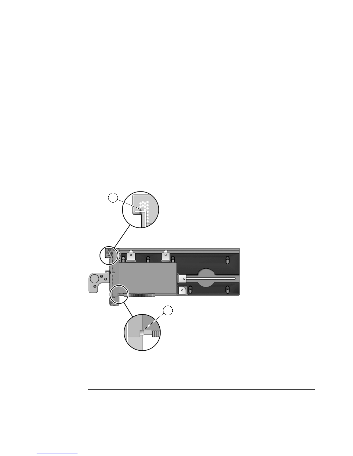
The tab (item 2 in
FIGURE 1-22) fits in a notch at the bottom of the PCI card. The tab
helps to align the card when you install it in the carrier. (Note that some card types
might not have the notch).
Note – The tab lifts the front of the card out of the card connector when you remove
the carrier from the I/O boat. If you cannot use a type C lock (
FIGURE 1-15) to support
the bottom of the PCI card, the card alignment tab is the only point that can provide
support to lift the card out of the socket.
FIGURE 1-23 shows how the bracket fits over the card alignment post.
Chapter 1 Overview 1-29
Page 44

FIGURE 1-23 Card Alignment Post (Detail)
1
2
3
Figure Legend
1 Carrier front housing
2 Card alignment post
3 PCI card bracket
1-30 External I/O Expansion Unit Installation and Service Manual for SPARC Enterprise T5xxx Servers • April 2011
Page 45
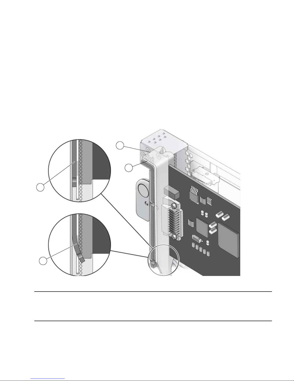
Internal RFI Gasket
An RFI gasket is located inside the carrier housing, next to the card alignment post.
(A smaller RFI gasket is located on the outside of the carrier housing.) When you
insert the PCI card into the carrier, be sure that the bottom of the metal card bracket
does not scrape or loosen the bottom of the gasket (
The gasket material is flexible enough that you might not notice that the bracket has
dislodged the gasket. Remember to inspect the condition of this gasket before you
install the carrier in the I/O boat.
FIGURE 1-24 Internal RFI Gasket
FIGURE 1-24).
1
2
3
4
Figure Legend
1 PCI card
2 RFI gasket (extends to the bottom front of the PCI carrier)
3 Correct example: the RFI gasket lies flat
4 Incorrect example: the card bracket has hooked behind the RFI gasket
Chapter 1 Overview 1-31
Page 46
1.3.6 Carrier Keys
Each carrier is keyed to a specific slot (FIGURE 1-25) in the I/O boat. The key is an M2
screw on the top of each carrier. Each carrier slot (0 through 6) will accept only a
carrier that has a key in the hole location for that slot.
FIGURE 1-25 Screw Hole Locations for the Carrier Slot Key
1
2
Figure Legend
1 Key (M2 screw)
2 Hole locations for carrier slots 0, 1, 2, 3 (front row)
Hole locations for carrier slots 4, 5, 6, 7 (rear row)
* Hole 0 and slot 0 are for the link card only.
† Hole 7 is reserved for future configurations.
*
†
If you replace a carrier, install the key in the keyhole that corresponds to the slot that
you use. A replacement carrier includes one key. It also includes an assortment of
labels. Affix the appropriate label (LINK 0 or PCIE n) to the front of the replacement
carrier for easy identification.
1-32 External I/O Expansion Unit Installation and Service Manual for SPARC Enterprise T5xxx Servers • April 2011
Page 47

1.4 External I/O Expansion Unit
Configurations
The External I/O Expansion Unit is available with one or two I/O boats.
1.4.1 Single Boat Configuration
The base configuration for an External I/O Expansion Unit has a single boat, with a
filler panel in the second boat bay.
A link card in the host server connects to a link card in the External I/O Expansion
Unit. A link cable connects the two link cards.
The link kit includes a 13 ft/4 m cable.
1.4.2 Dual Boat Configuration
The dual boat configuration provides twelve I/O slots. Each of the I/O boats requires
its own link kit, so the host server must have two I/O slots available for this purpose.
Note – The maximum number of I/O boats that can be attached to a server can vary
according to the server model. See TABLE 1-1.
Note – If you are installing a second boat in the External I/O Expansion Unit, both
boats must be connected to the same host server. Do not connect the second boat to a
different server. The second boat can be connected to a different domain on the same
server, but not to a domain on a different server.
Note – Do not daisy-chain two boats (connect a boat to another boat through link
cards). Daisy-chain configurations are not allowed.
Chapter 1 Overview 1-33
Page 48

1.5 LEDs
LEDs are located on the front (FIGURE 1-26) and rear (FIGURE 1-27) of the chassis and
on individual PSUs.
See Appendix B for information about interpreting LED states.
FIGURE 1-26 LEDs on the Front of the Chassis
1 2 3 4
9
5
6
7
8
Figure Legend
1 Chassis locate (LED and switch) 7 PSU0 DC power
2 Chassis fault/service required 8 PSU0 AC power
3 Chassis power 9 PSU1 ready to remove
4 Chassis overtemp 10 PSU1 fault/locate
5 PSU0 ready to remove 11 PSU1 DC power
6 PSU0 fault/locate 12 PSU1 AC power
10 11
12
Note – The Locate LED is a lighted push-button switch. When the flashing of its
LED has helped you to locate the External I/O Expansion Unit, turn off the LED by
pressing the switch. Note that the LED does not turn off if you press less than 0.5
seconds. You can also manually turn on the LED by pressing the button.
1-34 External I/O Expansion Unit Installation and Service Manual for SPARC Enterprise T5xxx Servers • April 2011
Page 49

FIGURE 1-27 LEDs on the Rear of the Chassis
5 6 7
11 12
1 2 3 4
13
14
8 9 10
11 12
Figure Legend
1 Chassis locate (LED and switch) 8 I/O boat 1 ready to remove
2 Chassis fault/service required 9 I/O boat 1 fault/locate
3 Chassis power 10 I/O boat 1 DC power
4 Chassis overtemp 11 Link card data
5 I/O boat 0 ready to remove 12 Link card management
6 I/O boat 0 fault/locate 13 Slot attention/locate (all PCI carriers)
7 I/O boat 0 DC power 14 Slot power (all PCI carriers)
1.6 System Management
The PSUs contain temperature sensors. The PSUs can shut down automatically if
they detect an extreme temperature. The PSUs also have sensors for voltage and
current levels.
Chapter 1 Overview 1-35
Page 50

Temperature sensors are also located inside the I/O boats. FRU ID circuits are located
on the link cards, the PSUs, the I/O boats, and on the chassis centerplane.
Temperature data and FRU ID information is available on an I2C bus (Inter-IC bus)
in the External I/O Expansion Unit and the link cards.
The service processor in the host system can monitor the I2C bus in the External I/O
Expansion Unit. The service processor can power down the External I/O Expansion
Unit if parameters exceed maximum limits.
There is no service processor in the External I/O Expansion Unit itself.
For examples of software commands, see Appendix C.
1.6.1 Maximum Temperatures in the External I/O
Expansion Unit
TABLE 1-2 summarizes the maximum temperatures for the External I/O Expansion
Unit. The table also includes error messages that the host might display if these
temperatures exceed the maximum values.
TABLE 1-3 Maximum Temperatures
Temperature Where Measured Comments
38˚C (100˚F) At the intake of the PSU The error message is:
Ext info /SYS/IOX@nnnn/PSn THERMCTRL/T_AMBIENT has
exceeded high warning threshold
54˚C (130˚F) Inside the PSU The error message is:
Ext info /SYS/IOX@nnnn/PSn THERMCTRL/T_HOTSPOT has
exceeded high warning threshold
Note: The PSU can turn itself off if its internal temperature
exceeds this value.
60˚C (140˚F) Inside the I/O boat The error messages are:
Ext info /SYS/IOX@nnnn/IOBn THERMCTRL/T_CHIP has
exceeded high warning threshold
Ext info /SYS/IOX@nnnn/IOBn THERMCTRL/T_HOTSPOT has
exceeded high warning threshold
65˚C (150˚F) Inside the I/O boat The error messages are:
Ext info /SYS/IOX@nnnn/IOBn THERMCTRL/T_CHIP has
exceeded high critical threshold
Ext info /SYS/IOX@nnnn/IOBn THERMCTRL/T_HOTSPOT has
exceeded high critical threshold
1-36 External I/O Expansion Unit Installation and Service Manual for SPARC Enterprise T5xxx Servers • April 2011
Page 51

1.7 Site Preparation
The following information summarizes installation requirements for the External I/O
Expansion Unit.
For additional specifications and compliance information, see Appendix A.
1.7.1 Physical Requirements
■ The External I/O Expansion Unit with the cable management unit attached is 17.3
in. (440 mm) wide and 39.4 in. (1000 mm) deep.
■ The movement of air through the External I/O Expansion Unit chassis is from
front to back.
■ The External I/O Expansion Unit is four rack units tall (6.9 inches/175 mm).
■ Service access to the External I/O Expansion Unit is from the front or rear. The
mounting rails do not slide.
■ The link kit includes a 13 ft/4 m cable.
■ The maximum weight of the External I/O Expansion Unit is approximately 81
pounds (36.8 kg).
Caution – Mount the heaviest subassemblies at the lowest available opening in a
rack to minimize the precarious effects of a top-heavy system.
Note – Do not install another product between two External I/O Expansion Units if
the product is short in height and shorter in depth than the External I/O Expansion
Units. If there is little space between the upper and lower External I/O Expansion
Units, there might not be enough space for your hands and arms to connect cables on
the rear of the product.
1.7.2 Electrical Requirements
■ The maximum wattage per PCI card is 25 watts.
■ Two AC cords (supplied) must be used with the internal AC cables (FIGURE 1-2).
■ The supply voltage is 100 VAC to 240 VAC, 50-60 Hz.
■ The maximum power rating of External I/O Expansion Unit is 600 watts.
Chapter 1 Overview 1-37
Page 52

1.8 Service Information
Service and installation information is also available on service labels that are located
on the External I/O Expansion Unit top cover and on the dummy cards that are
shipped with new carriers.
TABLE 1-4 Service Information Summary
Topic Comments
Access • Service access to the External I/O Expansion Unit is from the
front or rear of the unit.
• The top cover is removable.
Air flow • Air flow in the External I/O Expansion Unit is from front to
back.
• Fans are located in the power supply units. There are no
separate fans or fan trays.
• The PSU and I/O boat slots have pivoting metal flaps that drop
down to close the slots when a PSU or I/O boat is removed.
This prevents the loss of cooling air.
Mounting brackets The External I/O Expansion Unit is mounted on fixed brackets.
Sliding rails are not available for this product.
PCI cable removal • When removing cables such as LAN cables, if you have
difficulty unlatching the connector, press the latch with a
flathead screwdriver to remove the cable.
AC cables and cords • The internal AC cables (
are damaged, replace the chassis.
• Each internal AC cable connects to only one PSU. Connect both
AC cables to AC power to ensure that both PSUs are
operational.
• The internal AC cables are not connected directly to AC voltage.
Use the AC power cords to connect the internal AC cables to AC
voltage.
• Do not use AC cables designed for other products with the
External I/O Expansion Unit.
FIGURE 1-2) are not removable. If they
1-38 External I/O Expansion Unit Installation and Service Manual for SPARC Enterprise T5xxx Servers • April 2011
Page 53

TABLE 1-4 Service Information Summary (Continued)
Topic Comments
Link cables • The link kit has one cable. The connector is designed in a way
such that it cannot be connected upside down.
Jumpers • The External I/O Expansion Unit does not have jumper pins.
• For information about any jumper pins that might be present on
a specific PCI card, see the instructions that came with the card.
System serial number • For a new system, the system serial number is located on labels
on the chassis bezel and inside the right I/O boat bay.
• For a FRU chassis, the system serial number is located inside the
left I/O boat bay. Two additional serial number labels are
included to be placed on the chassis bezel.
1.9 Electrostatic Discharge Precautions
Caution – Circuit board components are vulnerable to damage by electrostatic
discharge (ESD). An electrostatic charge can build up on the human body and then
discharge when you touch a board. Such discharge can be produced by walking
across a carpet and touching a board, or by other similar cause. Before handling any
board, ensure that you dissipate your body’s charge. Touch a conductive surface of
the chassis or other element connected to common earth ground to discharge the
static electricity present in your body.
To minimize risk of ESD damage:
■ Handle the board by the edges only.
■ Store the board in an antistatic bag.
■ Use a grounding strap and an ESD mat whenever you work on a board.
Chapter 1 Overview 1-39
Page 54

1-40 External I/O Expansion Unit Installation and Service Manual for SPARC Enterprise T5xxx Servers • April 2011
Page 55

CHAPTER
2
Installing the External I/O
Expansion Unit in a Rack
The following topics are in this chapter:
■ Section 2.1, “Tools” on page 2-1
■ Section 2.2, “Installing the Mounting Brackets in a Rack” on page 2-2
■ Section 2.3, “Installing the External I/O Expansion Unit in the Rack” on page 2-7
■ Section 2.4, “Installing the Cable Management Unit” on page 2-9
■ Section 2.5, “Installing the AC Cords” on page 2-13
■ Section 2.6, “Installing the Link Kit” on page 2-16
2.1 Tools
You need the following tools for this installation:
■ Phillips No. 1 screwdriver
■ Phillips No. 2 screwdriver
■ ESD-protected mat and a grounding strap
■ (Suggested) digital voltmeter to verify correct grounding
2-1
Page 56

2.2 Installing the Mounting Brackets in a
Rack
The External I/O Expansion Unit mounting kit (FIGURE 2-1) includes a right-side
mounting bracket and a left-side mounting bracket. The mounting brackets are
adjustable for length and are shipped unassembled. The mounting kit includes two
chassis lock brackets.
FIGURE 2-1 Mounting Kit
1
2
3
4
Figure Legend
1 Left mounting bracket
2 Right mounting bracket
3 Left chassis lock bracket
4 Right chassis lock bracket
1. Use an antistatic strap for this procedure.
2. Locate a suitable mounting location in the rack.
■ The External I/O Expansion Unit occupies a height of four rack units (6.9 in./175
mm).
■ Mount the heaviest subassemblies at the lowest available opening to minimize the
precarious effects of a top-heavy system.
2-2 External I/O Expansion Unit Installation and Service Manual for SPARC Enterprise T5xxx Servers • April 2011
Page 57

■ If you are installing more than one External I/O Expansion Unit, install them
together. Do not install a shorter subassembly between External I/O Expansion
Unit where the rear of the shorter subassembly might difficult to reach.
■ If the rack is marked with rack units, place the mounting bracket so that the lower
screw hole on the bracket is one hole above an RU mark (
FIGURE 2-2). This aligns
the mounting bracket with the lower RU mark.
FIGURE 2-2 Typical Rack Unit Marks
3. Using No. 2 Phillips screws, attach the chassis lock brackets to the sides of the
External I/O Expansion Unit (
FIGURE 2-3).
Chapter 2 Installing the External I/O Expansion Unit in a Rack 2-3
Page 58

FIGURE 2-3 Installing the Chassis Lock Brackets
4. Loosen the screws (FIGURE 2-4) that hold the sliding flanges to the mounting
brackets.
This action allows the rear flanges to adjust to fit different rack depths.
2-4 External I/O Expansion Unit Installation and Service Manual for SPARC Enterprise T5xxx Servers • April 2011
Page 59

FIGURE 2-4 Sliding Flange
Figure Legend
1
2
1 Sliding flange
2 Flange crews
5. If your rack has threaded holes, continue at Step 7.
6. If your rack has square holes, install cage nuts in the rack pillars.
TABLE 2-1 lists the locations for the cage nuts. Note that these are relative locations.
Adjust the actual hole locations as needed to leave space for a power distribution
unit, additional External I/O Expansion Units, or other rack-mounted equipment.
Chapter 2 Installing the External I/O Expansion Unit in a Rack 2-5
Page 60

TABLE 2-1 Cage Nut Locations
Rack Unit Hole No. Front Rear
412
11
10 cage nut cage nut
39
8
7
2 6 cage nut cage nut
5 cage nut cage nut
4
13
2 cage nut cage nut
1
7. Attach the mounting brackets to the rack (FIGURE 2-5):
a. At the front of the rack, orient the hooked portion of the mounting bracket
away from you.
b. Loosely attach the front of the mounting bracket to the rack.
Install and tighten the screws, then loosen each screw approximately one-half
turn.
c. Repeat Step a and Step b for the second mounting bracket.
d. At the rear of the rack, slide the end of each mounting bracket to fit the depth
of the rack.
e. Loosely attach the rear ends of the mounting brackets to the rack.
f. Narrow the space between the rear ends of the mounting brackets by sliding
the ends of the brackets toward each other.
Note – At the front of the rack, the space between the brackets should be equal to or
slightly wider than the width of the External I/O Expansion Unit chassis. At the rear
of the rack, the space between the brackets should be slightly narrower than the
width of the External I/O Expansion Unit chassis. This arrangement allows the
correct fitting of the brackets to the sides of the External I/O Expansion Unit. See
Section 2.3, “Installing the External I/O Expansion Unit in the Rack” on page 2-7.
2-6 External I/O Expansion Unit Installation and Service Manual for SPARC Enterprise T5xxx Servers • April 2011
Page 61
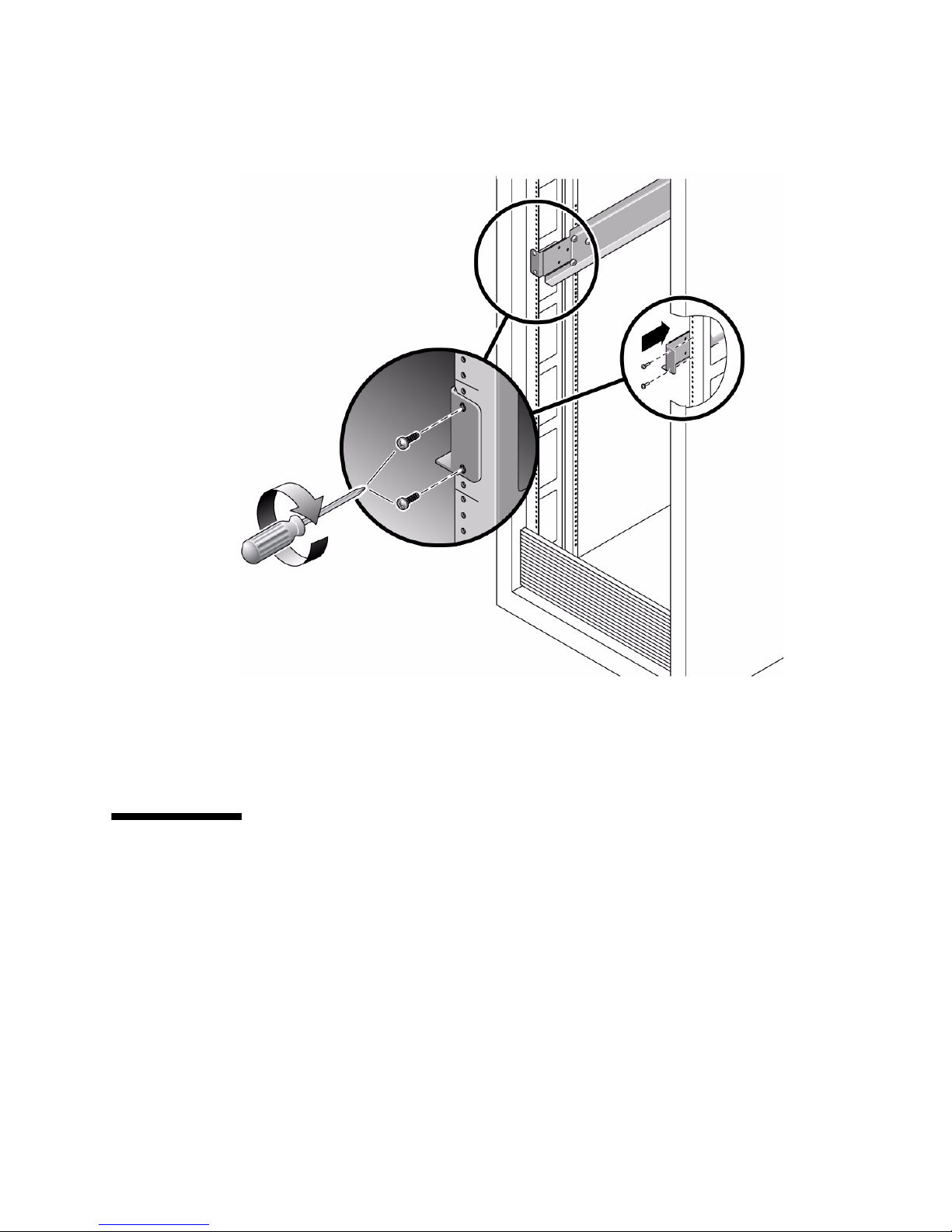
FIGURE 2-5 Installing the Mounting Brackets in a Rack
8. Tighten the screws at the front of the rack.
9. Verify that the brackets at the rear of the rack can still slide slightly to the left
and right.
2.3 Installing the External I/O Expansion
Unit in the Rack
1. Use an antistatic strap for this procedure.
2. Place the External I/O Expansion Unit on the front of the mounting brackets and
slide the External I/O Expansion Unit into the rack.
As you slide the External I/O Expansion Unit into the rack, the sides of the
External I/O Expansion Unit chassis push the ends of the brackets apart from each
other. When the chassis is almost completely in the rack, bulges on the underside
Chapter 2 Installing the External I/O Expansion Unit in a Rack 2-7
Page 62

of the chassis contact hooks that are located on the mounting brackets, wedging
the mounting brackets tightly against the sides of the chassis. This wedging action
stabilizes the External I/O Expansion Unit and is necessary to reduce the amount
of vibration that occurs when the system is running.
3. Tighten the screws at the rear of the mounting brackets.
4. Lock the front of the External I/O Expansion Unit in place with two screws on
each side (
FIGURE 2-6 Installing the External I/O Expansion Unit in the Rack
FIGURE 2-6).
2-8 External I/O Expansion Unit Installation and Service Manual for SPARC Enterprise T5xxx Servers • April 2011
Page 63

2.4 Installing the Cable Management Unit
At the rear of the rack, install the cable management support brackets:
1. Use an antistatic strap for this procedure.
2. Place the support brackets just above the chassis mounting brackets (
FIGURE 2-7)
and loosely attach the support brackets to the rack with two screws each.
Do not tighten the screws yet.
Note – The cable management unit includes one cable plate, either type A
(FIGURE 2-8)ortype B (FIGURE 2-9).
■ Use the type A cable plate in racks that allow the routing of cables along both
sides of the rack.
■ Use the type B cable plate in racks that allow the routing of cables only along the
right side of the rack.
Chapter 2 Installing the External I/O Expansion Unit in a Rack 2-9
Page 64
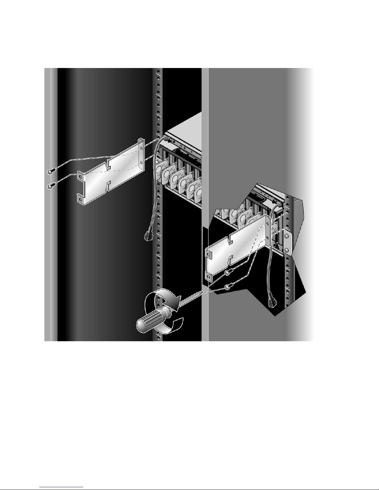
FIGURE 2-7 Installing the Support Brackets
2-10 External I/O Expansion Unit Installation and Service Manual for SPARC Enterprise T5xxx Servers • April 2011
Page 65

FIGURE 2-8 Type A Cable Plate
FIGURE 2-9 Type B Cable Plate
Chapter 2 Installing the External I/O Expansion Unit in a Rack 2-11
Page 66

3. Place the cable plate between the support brackets (FIGURE 2-10).
On each side of the cable plate, the forward tab rests on the bottom of the large
cutout in the support bracket. The rear tab rests in a small depression in the top of
the support bracket. This is the normal operating position for the cable plate.
FIGURE 2-10 Cable Plate and Support Bracket, Side View
1
2
3
Figure Legend
1 Cable plate
2 Support bracket
3 Supporting tabs on the cable plate
4. Tighten the green cable plate locking screws at each side of the cable plate.
5. Tighten the mounting screws on the support brackets.
2-12 External I/O Expansion Unit Installation and Service Manual for SPARC Enterprise T5xxx Servers • April 2011
Page 67

2.5 Installing the AC Cords
1. Use an antistatic strap for this procedure.
2. Attach an AC cord to an internal AC cable at the rear of the External I/O
Expansion Unit, then connect the AC cord to an AC outlet.
■ The PSUs should be connected to two independent external AC power sources so
that service will not be interrupted if one AC power source fails.
■ For the type A cable plate, route the AC cords along the nearest side of the rack.
■ For the type B cable plate, route the left AC cord over the top of the cable plate to
the right side of the rack. Place the connector of the left AC internal cable in the
rectangular opening in the top of the type B cable plate to save space.
Note – Do not attempt to connect the internal AC cable directly to an AC socket
(power distribution unit or power strip). You must use one of the AC cords supplied
with the External I/O Expansion Unit.
3. Attach an AC cord to the remaining internal AC cable as in Step 2.
Note – The fan might turn on when you insert a power supply into the External I/O
Expansion Unit. This is normal behavior if you are replacing a PSU while the other
PSU is powered up.
Chapter 2 Installing the External I/O Expansion Unit in a Rack 2-13
Page 68

FIGURE 2-11 AC Cables for Type A Cable Management Plate
1
2
Figure Legend
1 Internal AC cable, left
2 Internal AC cable, right
2-14 External I/O Expansion Unit Installation and Service Manual for SPARC Enterprise T5xxx Servers • April 2011
Page 69
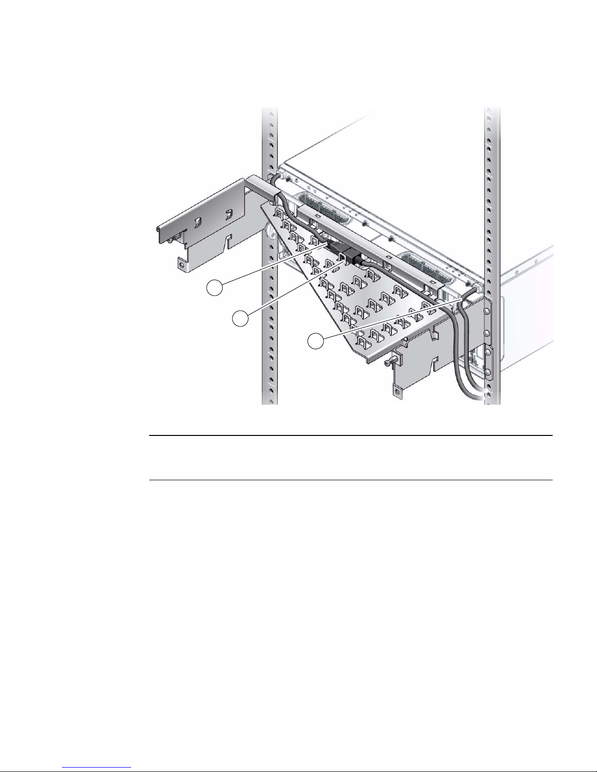
FIGURE 2-12 AC Cables and Cords for Type B Cable Plate
1
2
3
Figure Legend
1 Internal AC cable, left
2 AC cord (connectors are placed in rectangular opening to reduce height)
3 Internal AC cable, right
Chapter 2 Installing the External I/O Expansion Unit in a Rack 2-15
Page 70

4. If you wish to test the External I/O Expansion Unit for basic electrical
functionality, do the following:
a. Turn on the PSU AC switches.
The switches are located on the front of the power supplies.
The LEDs on the power supplies should display the following indications after
a short initialization period.
TABLE 2-2 Normal PSU Indications
LED Indication
AC Power On (green LED)
DC Power On (green LED)
For other LED combinations, see
TABLE B-4.
b. Turn off the PSU AC switches.
The LEDs on the PSUs continue glowing until DC current in the PSUs is
depleted. This can take approximately five to ten seconds.
2.6 Installing the Link Kit
A link kit includes two identical link cards, one for the host server and one for the
I/O boat. You can install either card in either location.
The link card in the I/O boat is always installed in boat slot 0. If your External I/O
Expansion Unit has two I/O boats, then link cards must be located in slot 0 of both
boats.
Note – If you are installing a second boat in the External I/O Expansion Unit, both
boats must be connected to the same host server. Do not connect the second boat to a
different server. The second boat can be connected to a different domain on the same
server, but not to a domain on a different server.
Note – Do not daisy-chain two boats (connect a boat to another boat through link
cards). Daisy-chain configurations are not allowed.
2-16 External I/O Expansion Unit Installation and Service Manual for SPARC Enterprise T5xxx Servers • April 2011
Page 71
Note – The minimum bend radius for the link cable is 1.85 in. (47 mm).
1. Use an antistatic strap for this procedure.
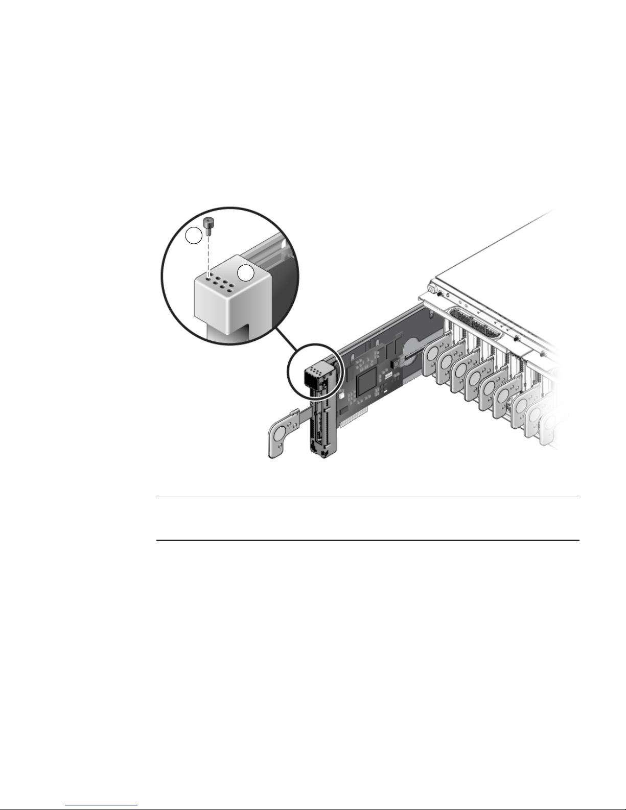
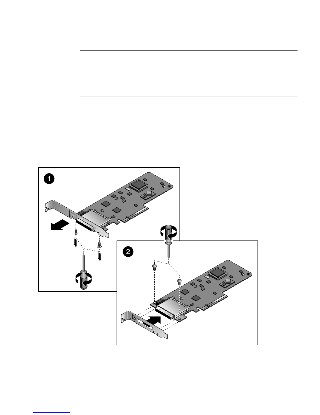
2. Install a low profile bracket on one link card, as follows.
Note – The low profile bracket is used only in the host server. The link card in the
I/O boat must use a full height bracket.
a. At the rear of the card, remove two No. 1 Phillips screws from the full height
bracket, then pull the bracket off the card.
See detail 1 in
FIGURE 2-13 Installing the Low Profile Bracket
FIGURE 2-13.
Chapter 2 Installing the External I/O Expansion Unit in a Rack 2-17
Page 72

b. Fit the low profile bracket over the cable connector and use the two No. 1
Phillips screws to attach the bracket to the card.
See detail 2 in
FIGURE 2-13.
Note – A link kit might include an extra low profile bracket. If you are installing two
I/O boats in the External I/O Expansion Unit, there might be two unused low profile
brackets after you finish the installation.
3. Install the link card with the low profile bracket in the host server.
See the service manual for your host server for instructions for installing a PCI
card in a host slot.
4. If a link card is not already installed in the I/O boat, install it now.
a. Remove the carrier in slot 0 of the I/O boat.
Slot 0 is used for the link card. It is the leftmost slot in the boat. For details
about card removal and replacement, see Section 3.1, “Installing a PCI Card” on
page 3-1.
Caution – The carrier can be damaged during removal and during insertion. For
safe handling of the carrier, read the Cautions in Section 3.1, “Installing a PCI Card”
on page 3-1.
b. Install the link card in the carrier.
c. Install the carrier and link card in slot 0.
5. Connect the link cable to both link cards.
FIGURE 2-14 Link Cable Plug
2-18 External I/O Expansion Unit Installation and Service Manual for SPARC Enterprise T5xxx Servers • April 2011
Page 73

Note – If it is necessary to disconnect a link cable, pull the ring-shaped tab
approximately 0.15 in./2 mm in the direction shown by the arrow in FIGURE 2-15.
Caution – Do not pull the ring tab more than 0.15 in./2 mm, or it will break. When
disconnecting the cable from a link card, pull the cable plug while pulling carefully
on the ring tab.
FIGURE 2-15 Link Cable Ring Tab
Chapter 2 Installing the External I/O Expansion Unit in a Rack 2-19
Page 74

2-20 External I/O Expansion Unit Installation and Service Manual for SPARC Enterprise T5xxx Servers • April 2011
Page 75

CHAPTER
3
Working With PCI Cards
This chapter gives procedures for installing PCI and link cards, and related cables.
■ Section 3.1, “Installing a PCI Card” on page 3-1
■ Section 3.2, “Replacing a PCI Card” on page 3-9
■ Section 3.3, “Installing Cables for PCI Cards” on page 3-16
3.1 Installing a PCI Card
1. Determine which card locks you will use to mount your PCI card on a carrier.
The size and shape of the PCI card affect the quantity and type of card locks you
use. Before you start this procedure, you must decide which locks you will use for
the PCI card. See Section 1.3.2, “Card Locks” on page 1-19
2. Use an antistatic strap for this procedure.
3. Unscrew the carrier locking screw (item 2 in
FIGURE 3-1) on the carrier handle.
3-1
Page 76
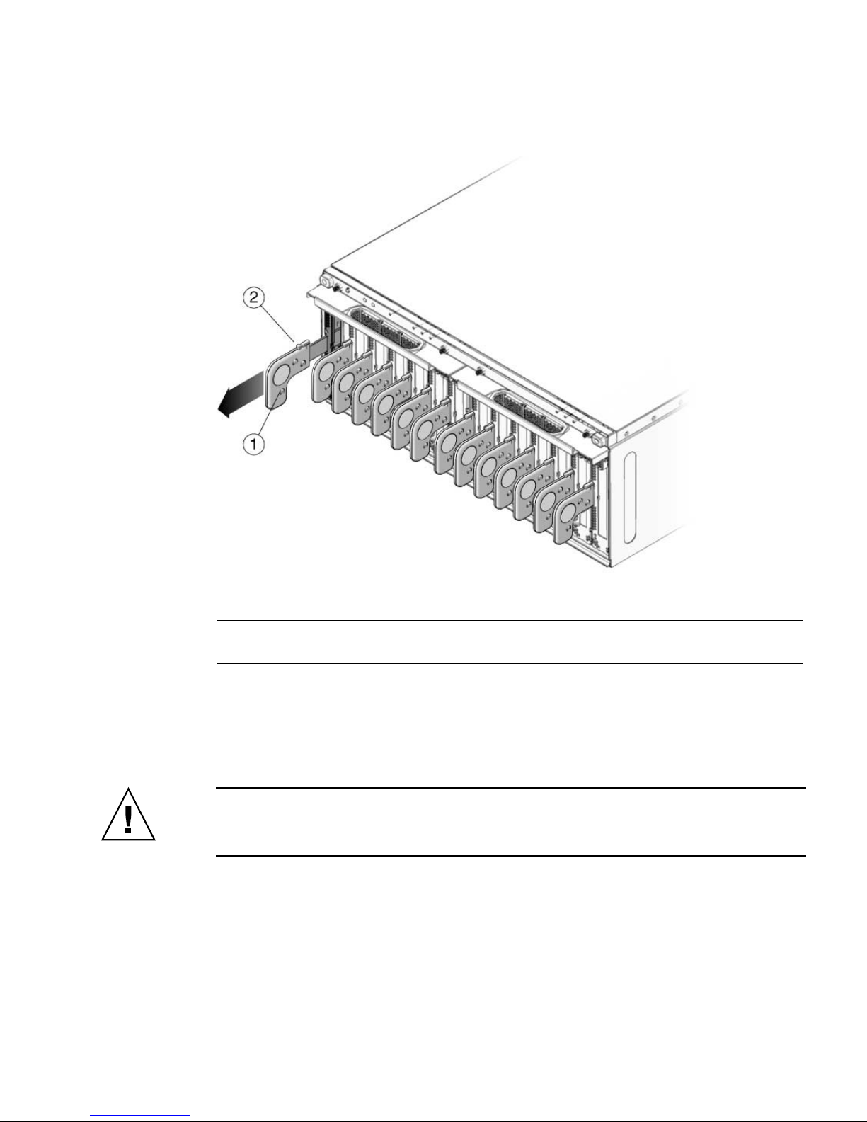
FIGURE 3-1 Unlocking and Removing a Carrier
Figure Legend
1 Carrier handle
2 Carrier locking screw
4. Press lightly on the front of the carrier, and pull out the carrier handle until it
clicks into the open position (approximately 1.5 in./38 mm).
Pressing the front of the carrier prevents movement of the carrier when you pull
the carrier handle.
Caution – Pulling the carrier handle raises the carrier plate. If the carrier moves
forward before the carrier plate is completely raised, the plastic locator bar
(FIGURE 3-2) might be damaged by hitting the lower front edge of the I/O boat.
3-2 External I/O Expansion Unit Installation and Service Manual for SPARC Enterprise T5xxx Servers • April 2011
Page 77

FIGURE 3-2 Locator Bar on Carrier
5. Pull the carrier out of the slot and place it on an antistatic work surface.
6. Press the locking latch (
FIGURE 3-3) while you push the carrier handle into the
closed position.
This action lowers the carrier plate, giving you more room to move the PCI card
into place on the carrier.
FIGURE 3-3 Closing the Carrier Handle
1
2
Figure Legend
1 Push carrier handle to the right
2 Push locking latch to the left
Chapter 3 Working With PCI Cards 3-3
Page 78

7. Place the carrier on a padded static-safe surface and loosen the card lock screws.
The screws are on the back of the carrier (
FIGURE 3-4 Screws for Card Locks
FIGURE 3-4).
1
Figure Legend
1 Card lock screws
8. Turn the carrier over and remove the dummy card or PCI card.
9. For very small PCI cards (1.25 in./31 mm tall or 3.0 in./76 mm wide), it is
necessary to do one or both of the following:
■ Move the long card lock (type B lock) from the horizontal slider slot to the front
vertical slider slot, then slide it down to reach the top of the PCI card.
■ Rotate the small card lock (type C lock) and slide it to the rear edge of the PCI
card.
See
FIGURE 1-19 and FIGURE 1-20 for examples.
10. Place the PCI card on the carrier.
a. Place the front of the card inside the housing (
FIGURE 3-5).
3-4 External I/O Expansion Unit Installation and Service Manual for SPARC Enterprise T5xxx Servers • April 2011
Page 79

FIGURE 3-5 Inserting the PCI Card
1
Figure Legend
1 See the following caution.
Caution – Do not allow the bottom edge of the PCI card bracket to tear the RFI
gasket in the front of the carrier (FIGURE 3-5).
b. A rectangular notch is located on the bottom front of the PCI card. Fit the
notch over the card alignment tab (item 1 in
card bracket over the card alignment post (item 2 in
FIGURE 3-6), then fit the top of the
FIGURE 3-6).
Chapter 3 Working With PCI Cards 3-5
Page 80

FIGURE 3-6 Placing the PCI Card on the Carrier
2
1
Figure Legend
1 Card alignment tab
2 Card alignment post
11. Attach the PCI card to the carrier with one card lock:
a. Slide a card lock to the right edge of the PCI card.
b. Hold the card in place and partially tighten the card lock screw.
Push the card lock against the card with sufficient pressure to slightly compress
the RFI gasket.
c. Verify that the PCI card is not tilted, then tighten the card lock screw.
3-6 External I/O Expansion Unit Installation and Service Manual for SPARC Enterprise T5xxx Servers • April 2011
Page 81

FIGURE 3-7 Using Card Lock to Hold the PCI Card
1
Figure Legend
1 Card lock
12. Slide the remaining card locks to the edges of the PCI card and tighten the
screws.
The shape of a PCI card might prevent the use of some card locks. The minimum
requirement is one card lock on the side of the PCI card and one card lock on the
top.
Note – If the card lock screws are loose, the card locks will slip. The PCI card will
not seat properly.
Caution – If the bottom card lock (Type C) is not used, leave it at the far right side
of the slot (
FIGURE 3-8). The PCI card will not seat properly if the bottom of the card
lock touches the card socket.
FIGURE 3-8 Correct Location for an Unused Type C Card Lock
1
Figure Legend
1 Location of type C card lock when not in use
Chapter 3 Working With PCI Cards 3-7
Page 82

Caution – Do not apply excessive pressure on the upper card locks. Too much
pressure will bend the PCI card bracket. See FIGURE 3-9.
FIGURE 3-9 Excessive Pressure Bends the PCI Card Bracket
Figure Legend
1 Moderate pressure on an upper card lock holds the PCI card in a horizontal position.
2 Excessive pressure bends the PCI card bracket.
13. Pull the carrier handle into the fully open position to raise the carrier plate.
If the carrier plate is not completely raised, the bottom edge will hit the card socket
in the I/O boat in Step 14 and Step 15.
14. Carefully place the replacement carrier in the card guides at the top and bottom
of the carrier slot in the I/O boat.
15. Push the carrier into the carrier slot.
Caution – Do not press the carrier handle while you push the carrier into the slot.
Push only the front of the carrier when seating the carrier in the slot. Pushing the
carrier handle might damage the carrier plate by causing it to drop down before the
carrier is fully seated in the slot.
16. Push the carrier handle into the closed position (
FIGURE 3-10).
This action seats the PCI card in the card socket.
3-8 External I/O Expansion Unit Installation and Service Manual for SPARC Enterprise T5xxx Servers • April 2011
Page 83

Caution – If the carrier handle does not close easily, the PCI card might not be
seating properly in the card socket in the I/O boat. Remove the carrier and inspect
the PCI card. If the bottom of the PCI card is not perfectly horizontal, loosen the card
locks and realign the card on the carrier. For troubleshooting information, see
Appendix E.
FIGURE 3-10 PCI Card and Carrier
Figure Legend
1 Carrier handle (in closed position)
2 Carrier locking screw
17. Use the carrier locking screw located on the top of the handle to lock the carrier
handle in place.
18. Add the PCI card to an Oracle Solaris domain.
For details, refer to the service manual for your host server.
3.2 Replacing a PCI Card
Caution – If you install a PCI card while the External I/O Expansion Unit is
running, be prepared to complete the installation in approximately two minutes. If
you leave a carrier slot empty, the External I/O Expansion Unit might overheat.
1. Use an antistatic strap for this procedure.
2. Remove the PCI card from the Oracle Solaris domain.
For details, refer to the service manual for your host server.
Chapter 3 Working With PCI Cards 3-9
Page 84

3. Remove the carrier from the carrier slot in the I/O boat.
a. Loosen the carrier locking screw on the carrier handle.
b. Press lightly on the front of the carrier, and pull the carrier handle out fully.
Caution – Pulling the carrier handle raises the carrier plate. If the carrier moves
forward before the carrier plate is completely raised, the plastic locator bar
(FIGURE 3-2) might be damaged by hitting the lower front edge of the I/O boat.
c. Pull the carrier out of the carrier slot and place on an antistatic surface.
4. Press the locking latch (
FIGURE 3-11) while you push the carrier handle into the
closed position.
This action lowers the PCI card, facilitating the replacement of the card.
FIGURE 3-11 Closing the Carrier Handle
1
2
Figure Legend
1 Push carrier handle to the right
2 Push locking latch to the left
5. Remove the existing card from the carrier.
6. If you are installing an exact replacement, go to Step 8.
7. For very small PCI cards (1.25 in./31 mm tall or 3.0 in./76 mm wide), it is
necessary to do one or both of the following:
■ Move the long card lock (type B lock) from the horizontal slider slot to the front
vertical slider slot, then slide it down to reach the top of the PCI card.
■ Rotate the small card lock (type C lock) and slide it to the rear edge of the PCI
card.
See
FIGURE 1-19 and FIGURE 1-20 for examples.
3-10 External I/O Expansion Unit Installation and Service Manual for SPARC Enterprise T5xxx Servers • April 2011
Page 85

8. Place the PCI card on the carrier.
a. Place the front of the card inside the housing (
FIGURE 3-12 Inserting the PCI Card
FIGURE 3-12).
1
Figure Legend
1 See the following caution.
Caution – Do not allow the bottom edge of the PCI card bracket to tear the RFI
gasket in the front of the carrier (FIGURE 3-5).
b. A rectangular notch is located on the bottom front of the PCI card. Fit the
notch over the card alignment tab (item 1 in
card bracket over the card alignment post (item 2 in
FIGURE 3-6), then fit the top of the
FIGURE 3-6).
Chapter 3 Working With PCI Cards 3-11
Page 86
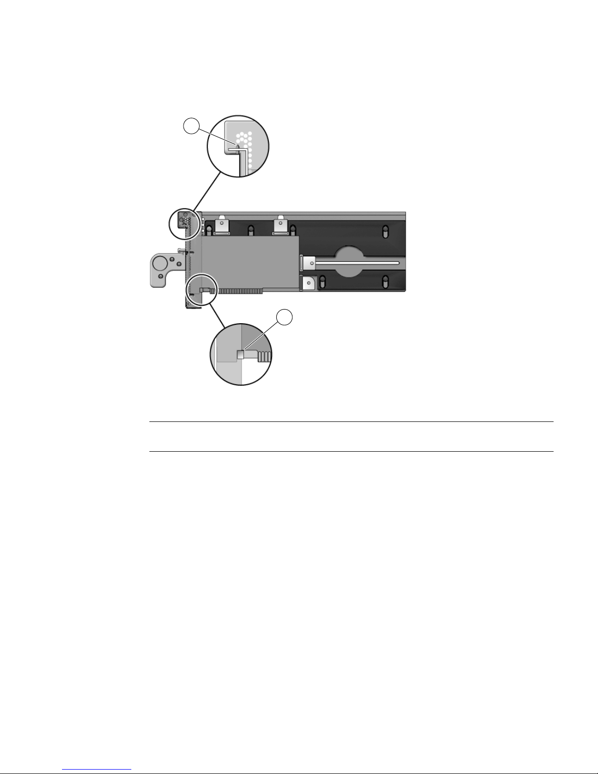
FIGURE 3-13 Placing the PCI Card on the Carrier
2
1
Figure Legend
1 Card alignment tab
2 Card alignment post
9. Attach the PCI card to the carrier with one card lock:
a. Slide a card lock to the right edge of the PCI card.
b. Hold the card in place and partially tighten the card lock screw.
c. Verify that the PCI card is not tilted, then tighten the card lock screw.
3-12 External I/O Expansion Unit Installation and Service Manual for SPARC Enterprise T5xxx Servers • April 2011
Page 87

FIGURE 3-14 Using Card Lock to Hold the PCI Card
1
Figure Legend
1 Card lock
10. Slide the remaining card locks to the edges of the PCI card and tighten the
screws.
The shape of a PCI card might prevent the use of some card locks. The minimum
requirement is one card lock on the side of the PCI card and one card lock on the
top.
Note – If the card lock screws are loose, the card locks will slip and the PCI card will
not seat properly.
Caution – If the bottom card lock (type C) is not used, leave it at the far right side of
the slot (
FIGURE 3-15). The PCI card will not seat properly if the bottom of the card
lock touches the card socket.
FIGURE 3-15 Location for an Unused Type C Card Lock
1
Figure Legend
1
Correct location and orientation for an unused type C card lock
Chapter 3 Working With PCI Cards 3-13
Page 88

Caution – Do not apply excessive pressure on the upper card locks. Too much
vertical pressure will bend the PCI card bracket. See FIGURE 3-16.
FIGURE 3-16 Excessive Pressure Bends the PCI Card Bracket
Figure Legend
1 Moderate pressure on an upper card lock holds the PCI card in a horizontal position.
2 Excessive pressure on an upper card lock can bend the PCI card bracket.
11. Pull the carrier handle into the fully open position to raise the carrier plate.
Caution – If the carrier plate is not completely raised when you insert the carrier in
Step 13, the plastic locator bar (
FIGURE 3-17) might break by hitting the lower front
edge of the I/O boat.
3-14 External I/O Expansion Unit Installation and Service Manual for SPARC Enterprise T5xxx Servers • April 2011
Page 89
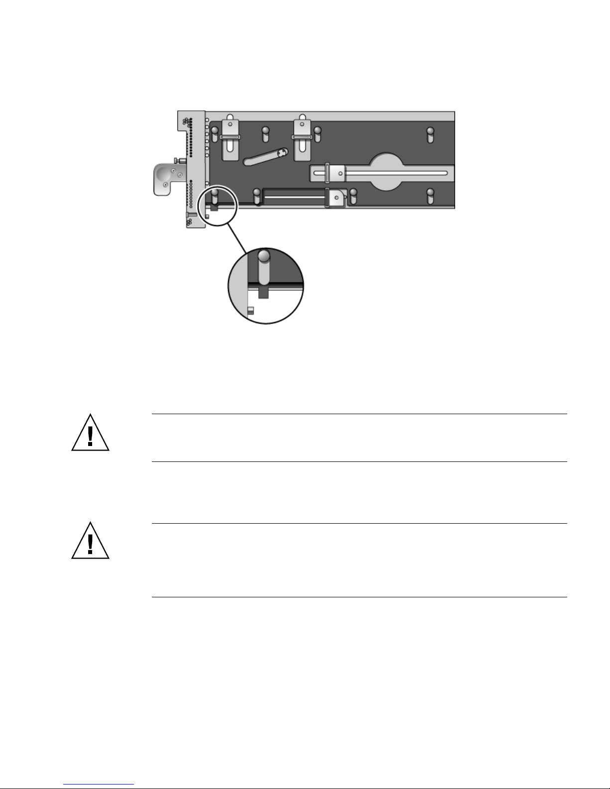
FIGURE 3-17 Locator Bar on Carrier (Carrier Handle Shown in the Closed Position)
12. Carefully place the carrier in the card guides at the top and bottom of the carrier
slot in the I/O boat.
13. Press on the metal front panel of the carrier to push the carrier fully into the
carrier slot.
Caution – Do not press the plastic carrier handle during Step 13. If you press the
handle, the PCI card and the sliding carrier plate might suddenly fall, breaking the
plastic locator bar (FIGURE 3-17) by hitting it against the lower edge of the I/O boat.
14. Push the carrier handle into the closed position.
This action seats the PCI card in the card socket.
Caution – If the carrier handle does not close easily, the PCI card might not be
seating properly in the card socket in the I/O boat. Remove the carrier and inspect
the PCI card. If the bottom of the PCI card is not perfectly horizontal, loosen the card
locks and realign the card on the carrier. For troubleshooting information, see
Appendix E.
Chapter 3 Working With PCI Cards 3-15
Page 90

FIGURE 3-18 PCI Card and Carrier
Figure Legend
1 Carrier handle (in closed position)
2 Carrier locking screw
15. Use the carrier locking screw located on the top of the handle to lock the carrier
handle in place.
16. Add the PCI card to an Oracle Solaris domain.
For details, refer to the service manual for your host server.
3.3 Installing Cables for PCI Cards
1. Use an antistatic strap for this procedure.
2. Route the cables across the top of the cable management unit as shown in
FIGURE 3-19 or FIGURE 3-20.
a. Route the cables along the right and left sides of the rack.
b. Place the ends of the cables on the top of the cable plate, then curve the
cables down to the corresponding PCI cards.
c. Use cable ties to hold the cables in place on the top of the cable management
unit.
Note – Before tightening the cable ties, ensure that each cable has a service loop
(freedom of movement) of at least 2 in./50 mm. This allows the cable plate and
cables to be moved from the normal position (
without the need to untie the cables.
3-16 External I/O Expansion Unit Installation and Service Manual for SPARC Enterprise T5xxx Servers • April 2011
FIGURE 4-4) to the service position
Page 91

FIGURE 3-19 Example of Cable Management for the Type A Cable Plate
Chapter 3 Working With PCI Cards 3-17
Page 92
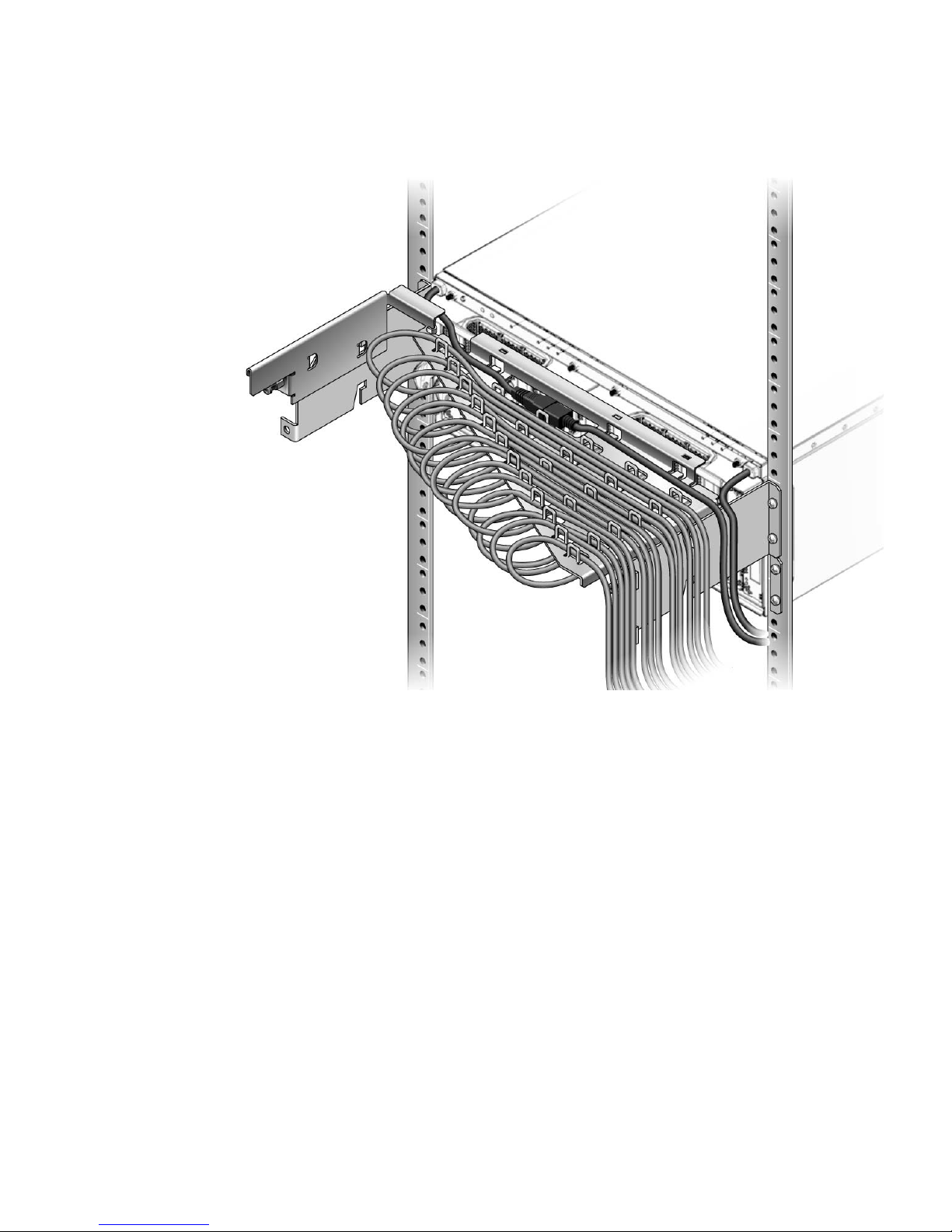
FIGURE 3-20 Example of Cable Management for the Type B Cable Plate
3. Attach I/O cables from the PCI cards and their respective devices or network
ports.
3-18 External I/O Expansion Unit Installation and Service Manual for SPARC Enterprise T5xxx Servers • April 2011
Page 93

CHAPTER
4
Servicing and Replacing
Components
This chapter includes the service procedures for replacing field-replaceable units and
installing optional assemblies.
This chapter includes the following topics:
■ Section 4.1, “Service Procedures Task Map” on page 4-2
■ Section 4.2, “Replacing a Power Supply Unit” on page 4-3
■ Section 4.3, “Preparing the Cable Plate for Service” on page 4-5
■ Section 4.4, “Replacing a Carrier” on page 4-7
■ Section 4.5, “Replacing a Link Cable” on page 4-10
■ Section 4.6, “Replacing a Link Card in the Host Server” on page 4-10
■ Section 4.7, “Replacing a Link Card in an I/O Boat” on page 4-11
■ Section 4.8, “Installing a Second I/O Boat” on page 4-13
■ Section 4.9, “Replacing an I/O Boat” on page 4-16
■ Section 4.10, “Replacing the External I/O Expansion Unit Chassis” on page 4-21
4-1
Page 94

4.1 Service Procedures Task Map
TABLE 4-1 Service Task Map
FRU Task Comments
PCI card
PSU
Cable
Management
Carrier
Link
I/O boat
Chassis
• Install a new PCI card Section 3.1, “Installing a PCI Card” on page 3-1
• Replace an existing PCI card Section 3.2, “Replacing a PCI Card” on page 3-9
• Replace a PSU Section 4.2, “Replacing a Power Supply Unit” on page 4-3
• Prepare the cable plate for I/O boat
service
Section 4.3, “Preparing the Cable Plate for Service” on
page 4-5
• Replace a carrier Section 4.4, “Replacing a Carrier” on page 4-7
• Replace a link cable Section 4.5, “Replacing a Link Cable” on page 4-10
• Replace a link card • Section 4.6, “Replacing a Link Card in the Host Server”
on page 4-10
• Section 4.7, “Replacing a Link Card in an I/O Boat” on
page 4-11
• Install a second I/O boat Section 4.8, “Installing a Second I/O Boat” on page 4-13
• Replace an I/O boat • Section 4.9.1, “Replacing a Boat in a Single Boat
Configuration” on page 4-16
• Section 4.9.2, “Replacing a Boat in a Dual Boat
Configuration” on page 4-19
Replace the External I/O Expansion
Unit chassis
Section 4.10, “Replacing the External I/O Expansion Unit
Chassis” on page 4-21.
4-2 External I/O Expansion Unit Installation and Service Manual for SPARC Enterprise T5xxx Servers • April 2011
Page 95

4.2 Replacing a Power Supply Unit
This is a hot replacement procedure, meaning that the PSU can be replaced while the
system is still running, provided that a second PSU is working properly.
1. Use an antistatic strap for this procedure.
2. Unpack the new power supply unit and set it flat on an antistatic surface.
Caution – Do not rest a PSU vertically. The plastic electrical connector on the back is
breakable.
3. At the front of the defective PSU, turn off the PSU AC switch and verify that the
DC Power LED ( ) turns off.
4. Loosen the handle locking screw on the PSU handle.
5. Unlock the PSU by swinging the handle out 90 degrees into the fully open
position. (
6. Place a hand under the PSU to prevent it from falling, then pull the PSU out of
the External I/O Expansion Unit.
FIGURE 4-1)
Caution – The PSU is heavy (7.5 lb/3.4 kg).
When you can see the warning label on the top of the PSU, the PSU is almost fully
out of the PSU slot.
Caution – Do not allow the rear of the PSU to drop. The connector at the rear of the
PSU can be damaged if it strikes the edge of the slot.
A pivoting flap behind the PSU drops down to prevent loss of cooling air.
Chapter 4 Servicing and Replacing Components 4-3
Page 96

FIGURE 4-1 PSU
3
Figure Legend
1 Handle
2 Handle locking screw
3 Warning labels
1
2
7. Set the PSU flat on an antistatic surface.
8. Insert the new PSU into the External I/O Expansion Unit.
The pivoting flap automatically swings up and out of the way.
Note – The fan in the new PSU turns on immediately if the External I/O Expansion
Unit is running.
9. Turn the PSU handle 90 degrees into the closed position.
10. Secure the handle locking screw on the PSU handle.
11. Turn on the AC switch on the PSU.
The Fault/Locate LED ( ) on the PSU lights up momentarily during the
initialization then turns off. You should see the AC power ( ) and DC power
( ) LEDs turn on after the initialization.
For other LED indications, see Appendix B.
4-4 External I/O Expansion Unit Installation and Service Manual for SPARC Enterprise T5xxx Servers • April 2011
Page 97

4.3 Preparing the Cable Plate for Service
On the cable management unit, raise the cable plate (FIGURE 4-2 or FIGURE 4-3) to
provide easier removal of a PCI carrier or I/O boat.
1. Use an antistatic strap for this procedure.
2. Loosen two cable plate locking screws (item 3 in
3. Pull the cable plate toward you approximately 0.5 in./13 mm, then raise it
approximately 0.75 in./20 mm, until the bottom of the plate is above the tops of
the support brackets.
4. Push the cable plate forward to its service position (
plate rests on the support brackets.
The tabs on the sides of the cable plate should lie in the small notches on the tops
of the support brackets.
FIGURE 4-2 Type A Cable Plate
FIGURE 4-4).
FIGURE 4-4) so that the cable
Chapter 4 Servicing and Replacing Components 4-5
Page 98

FIGURE 4-3 Type B Cable Plate
The left side of FIGURE 4-4 shows the cable plate in its normal position.
The right side of the illustration shows the service position.
FIGURE 4-4 Cable Plate (Side Views of Normal and Service Positions)
2
1
3
Figure Legend
1 Cable plate in the normal position (lowered)
2 Cable plate in the service position (raised)
3 Cable plate locking screw (two places)
5. After the carrier or I/O boat has been replaced, move the cable plate down into
its normal position and tighten the cable plate locking screws.
4-6 External I/O Expansion Unit Installation and Service Manual for SPARC Enterprise T5xxx Servers • April 2011
Page 99

4.4 Replacing a Carrier
The External I/O Expansion Unit must be powered off during this procedure.
A carrier is keyed to a specific slot in an I/O boat. The key is an M2 screw
(
FIGURE 4-5).
FIGURE 4-5 Screw Hole Locations for the Carrier Slot Key
1
2
3
Figure Legend
1 Key
2 Keyholes 0-7
3 Carrier label
* Keyhole 7 is reserved for future use.
*
1. Use an antistatic strap for this procedure.
2. Stop the domains that are connected to the External I/O Expansion Unit.
For information about stopping a domain, refer to the documentation for the
server.
3. Move the cable plate to the service position:
Chapter 4 Servicing and Replacing Components 4-7
Page 100

a. Loosen the cable plate locking screw(s) (item 3 in FIGURE 4-4).
b. Pull the cable plate toward you approximately 0.5 in./13 mm, then raise it
approximately 0.75 in./20 mm, until the bottom of the plate is above the tops
of the support brackets.
c. Push the cable plate forward to its service position (item 2 in
FIGURE 4-4)so
that the cable plate rests on the support brackets.
The tabs on the sides of the cable plate should lie in the small notches on the
tops of the support brackets.
4. Disconnect the I/O cable(s) from the PCI card in the carrier.
5. Remove the carrier from the I/O boat:
a. Loosen the carrier locking screw on the carrier handle.
b. Pull the carrier handle out fully.
Caution – Pulling the carrier handle raises the carrier plate. If the carrier moves
forward before the carrier plate is completely raised, the plastic locator bar
(FIGURE 3-2) might be damaged by hitting the lower front edge of the I/O boat.
c. Pull the carrier out of the carrier slot and place it on an antistatic surface.
d. Press the locking latch (
FIGURE 3-3) while you push the carrier handle into the
closed position.
This action lowers the carrier plate, giving you more room to move the PCI
card into place on the carrier.
6. Install an M2 screw on the replacement carrier, in the key hole (
FIGURE 4-5) that
corresponds to the slot number of the defective carrier.
Carriers are keyed to specific slots in an I/O boat. If a carrier does not fit in a slot,
verify that the M2 screw is in the hole that corresponds to that slot.
7. Attach a label with the slot name and number to the carrier.
The replacement carrier includes an assortment of adhesive labels including LINK
0, PCIE 1, and so forth. Use the replacement label that corresponds to the label on
the defective carrier. Place the label just below the opening in the front of the
carrier (
FIGURE 4-5).
8. Transfer the PCI card from the defective carrier to the replacement carrier:
a. Remove the dummy card from the replacement carrier by loosening the
Phillips screws on the card locks.
4-8 External I/O Expansion Unit Installation and Service Manual for SPARC Enterprise T5xxx Servers • April 2011
 Loading...