

Sun Microsystems Sun StorEdge A1000, StorEdge D1000 Installation, Operation And Service Manual [en, fr, es, de]
Page 1
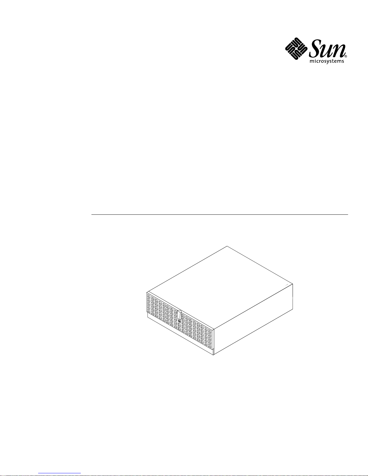
Sun StorEdge™A1000 and D1000
Installation, Operations, and
Service Manual
Sun Microsystems, Inc.
4150 Network Circle
Santa Clara, CA 95054 U.S.A.
650-960-1300
Part No. 806-2624-12
November 2002, Revision A
Send comments about this document to: [email protected]
Page 2

Copyright 2002Sun Microsystems,Inc., 4150Network Circle,Santa Clara,California 95054,U.S.A. All rightsreserved.
Sun Microsystems, Inc.has intellectualproperty rightsrelating totechnology embodiedin theproduct thatis described inthis document.In
particular,and withoutlimitation, theseintellectual propertyrights mayinclude one ormore ofthe U.S.patents listedat
http://www.sun.com/patentsand one or more additional patents or pending patent applications in the U.S. and in other countries.
This document and the product to which it pertains are distributed under licenses restricting their use, copying, distribution, and
decompilation. No part of the product or of this document may be reproduced in any form by any means without prior written authorization of
Sun and its licensors, if any.
Third-partysoftware, including font technology,is copyrighted and licensed fromSun suppliers.
Parts of the product may be derived from Berkeley BSD systems, licensed from the University of California. UNIX is a registeredtrademark in
the U.S. and in other countries, exclusively licensed through X/Open Company,Ltd.
Sun, Sun Microsystems,the Sun logo, AnswerBook2, docs.sun.com, Sun StorEdge, and Solaris are trademarks or registered trademarks of Sun
Microsystems,Inc. in the U.S. and in other countries.
All SPARC trademarks are used under license and are trademarks or registered trademarks of SPARCInternational, Inc. in the U.S. and in other
countries. Productsbearing SPARC trademarks arebased upon an architecturedeveloped by Sun Microsystems, Inc.
The OPEN LOOK and Sun™ Graphical User Interface was developed by Sun Microsystems,Inc. for its users and licensees. Sun acknowledges
the pioneering efforts of Xerox in researchingand developing the concept of visual or graphical user interfaces for the computer industry.Sun
holds a non-exclusive license from Xerox to the Xerox Graphical User Interface, which license also covers Sun’s licensees who implement OPEN
LOOK GUIs and otherwise comply with Sun’s written license agreements.
Use, duplication, or disclosureby the U.S.Government is subject to restrictionsset forth in the Sun Microsystems,Inc. license agreementsand as
providedin DFARS227.7202-1(a) and 227.7202-3(a) (1995), DFARS252.227-7013(c)(1)(ii) (Oct. 1998), FAR12.212(a) (1995), FAR52.227-19, or
FAR52.227-14 (ALTIII), as applicable.
DOCUMENTATION IS PROVIDED "AS IS" AND ALL EXPRESS OR IMPLIED CONDITIONS, REPRESENTATIONS AND WARRANTIES,
INCLUDING ANY IMPLIED WARRANTYOF MERCHANTABILITY,FITNESS FOR A PARTICULAR PURPOSE OR NON-INFRINGEMENT,
ARE DISCLAIMED, EXCEPT TO THE EXTENT THAT SUCH DISCLAIMERS ARE HELD TO BE LEGALLY INVALID.
Copyright 2002 Sun Microsystems, Inc., 4150 Network Circle, Santa Clara, California 95054, Etats-Unis. Tousdroits réservés.
Sun Microsystems,Inc. a les droits de propriété intellectuels relatants à la technologie incorporée dans le produit qui est décrit dans ce
document. En particulier,et sans la limitation, ces droits de propriété intellectuels peuvent inclure un ou plus des brevetsaméricains énumérés
à http://www.sun.com/patents et un ou les brevets plus supplémentaires ou les applications de brevet en attente dans les Etats-Unis et dans
les autrespays.
Ce produitou document est protégé par un copyright et distribué avec des licences qui en restreignentl’utilisation, la copie, la distribution, et la
décompilation. Aucune partie de ce produit ou document ne peut être reproduite sous aucune forme, parquelque moyen que ce soit, sans
l’autorisation préalable et écrite de Sun et de ses bailleurs de licence, s’il y ena.
Le logiciel détenu par des tiers, et qui comprend la technologie relative aux polices de caractères, est protégé par un copyright et licencié par des
fournisseurs de Sun.
Des parties de ce produit pourront êtredérivées des systèmes Berkeley BSD licenciés par l’Université de Californie. UNIX est une marque
déposée aux Etats-Unis et dans d’autres pays et licenciée exclusivement par X/Open Company,Ltd.
Sun, Sun Microsystems, le logo Sun, AnswerBook2, docs.sun.com, Sun StorEdge, et Solaris sont des marquesde fabrique ou des marques
déposées de Sun Microsystems, Inc. aux Etats-Unis et dans d’autres pays.
Toutesles marquesSPARCsont utilisées sous licence et sont des marques de fabrique ou des marques déposées de SPARCInternational, Inc.
aux Etats-Unis et dans d’autres pays. Les produits protant les marques SPARC sont basés sur une architecture développée par Sun
Microsystems,Inc.
L’interfaced’utilisation graphique OPEN LOOK et Sun™ a été développée par Sun Microsystems, Inc. pour ses utilisateurs et licenciés. Sun
reconnaîtles effortsde pionniers de Xerox pour la rechercheet le développment du concept des interfaces d’utilisation visuelle ou graphique
pour l’industrie de l’informatique. Sun détient une license non exclusive do Xeroxsur l’interface d’utilisation graphique Xerox, cette licence
couvrant également les licenciées de Sun qui mettent en place l’interface d ’utilisation graphique OPEN LOOK et qui en outre se conforment
aux licences écrites de Sun.
LA DOCUMENTATION EST FOURNIE "EN L’ÉTAT" ET TOUTES AUTRES CONDITIONS, DECLARATIONS ET GARANTIES EXPRESSES
OU TACITESSONT FORMELLEMENT EXCLUES, DANS LA MESURE AUTORISEE PARLA LOI APPLICABLE, Y COMPRIS NOTAMMENT
TOUTE GARANTIE IMPLICITE RELATIVE A LA QUALITE MARCHANDE, A L’APTITUDE A UNE UTILISATION PARTICULIERE OU A
L’ABSENCE DE CONTREFAÇON.
Please
Recycle
Page 3

Regulatory Compliance Statements
Your Sun product is marked to indicate its compliance class:
• Federal Communications Commission (FCC) — USA
• Industry Canada Equipment Standard for Digital Equipment (ICES-003) — Canada
• Voluntary Control Council for Interference (VCCI) — Japan
• Bureau of Standards Metrology and Inspection (BSMI) — Taiwan
Please read the appropriate section that corresponds to the marking on your Sun product before attempting to install the
product.
FCC Class A Notice
This device complies with Part 15 of the FCC Rules. Operation is subject to the following two conditions:
1. This device may not cause harmful interference.
2. This device must accept any interference received, including interference that may cause undesired operation.
Note: This equipment has been tested and found to comply with the limits for a Class A digital device, pursuant to Part 15 of
the FCC Rules. These limits are designed to provide reasonable protection against harmful interference when the equipment
is operated in a commercial environment. This equipment generates, uses, and can radiate radio frequency energy, and if it is
not installed and used in accordance with the instruction manual, it may cause harmful interference to radio communications.
Operation of this equipment in a residential area is likely to cause harmful interference, in which case the user will be required
to correct the interference at his own expense.
Shielded Cables: Connections between the workstation and peripherals must be made using shielded cables to comply with
FCC radio frequency emission limits. Networking connections can be made using unshielded twisted-pair (UTP) cables.
Modifications:Any modifications made to thisdevice that are not approved by Sun Microsystems,Inc. may void the authority
granted to the user by the FCC to operate this equipment.
FCC Class B Notice
This device complies with Part 15 of the FCC Rules. Operation is subject to the following two conditions:
1. This device may not cause harmful interference.
2. This device must accept any interference received, including interference that may cause undesired operation.
Note: This equipment has been tested and found to comply with the limits for a Class B digital device, pursuant to Part 15 of
the FCC Rules. These limits are designed to provide reasonable protection against harmful interference in a residential
installation. This equipment generates, uses and can radiate radio frequency energy and, if not installed and used in
accordance with the instructions, may cause harmful interference to radio communications. However, there is no guarantee
that interference will not occur in a particular installation. If this equipment does cause harmful interference to radio or
television reception, which can be determined by turning the equipment off and on, the user is encouraged to try to correct the
interference by one or more of the following measures:
• Reorient or relocate the receiving antenna.
• Increase the separation between the equipment and receiver.
• Connect the equipment into an outlet on a circuit different from that to which the receiver is connected.
• Consult the dealer or an experienced radio/television technician for help.
Shielded Cables: Connections between the workstation and peripherals must be made using shielded cables in order to
maintain compliance with FCC radio frequency emission limits. Networking connections can be made using unshielded
twisted pair (UTP) cables.
Modifications:Any modifications made to thisdevice that are not approved by Sun Microsystems,Inc. may void the authority
granted to the user by the FCC to operate this equipment.
iii
Page 4
ICES-003 Class A Notice- Avis NMB-003, Classe A
This Class A digital apparatus complies with Canadian ICES-003.
Cet appareil numérique de la classe A est conforme à la norme NMB-003 du Canada.
ICES-003 Class B Notice- Avis NMB-003, Classe B
This Class B digital apparatus complies with Canadian ICES-003.
Cet appareil numérique de la classe B est conforme à la norme NMB-003 du Canada.
iv Sun StorEdge A1000 and D1000 Installation, Operations, and Service Manual • November 2002
Page 5
BSMI Class A Notice
The following statement is applicable to products shipped to Taiwan and marked as Class A on the product compliance
label.
NOTE: Include the following BMSI DoC mark when requested to do so by Compliance Engineering. Otherwise, remove this
paragraph and graphic.
v
Page 6

Declaration of Conformity
Compliance ID: 1630
Product Name: Sun StorEdge A1000,Tabletop; Sun StorEdge D1000,Tabletop
This product has been tested and complies with:
EMC
USA - FCC Class B
This equipment complies with Part 15 of the FCC Rules. Operation is subject to the following two conditions:
1) This equipment may not cause harmful interference.
2) This equipment must accept any interference that may cause undesired operation.
European Union
This equipment complies with the following requirements of the EMC Directive 89/336/EEC:
EN55022 / CISPR22 (1985) Class B
EN50082-1 IEC801-2 (1991) 4 kV (Direct), 8 kV (Air)
IEC801-3 (1984)3 V/m
IEC801-4 (1988)1.0 kV Power Lines, 0.5 kV Signal Lines
EN61000-3-2/IEC1000-3-2(1994) Pass
Safety
This equipment complies with the following requirements of Low Voltage Directive 73/23/EEC:
EC Type Examination Certificates:
EN60950/IEC950
EN60950 w/ Nordic Deviations
Supplementary Information:
This product was tested and complies with all the requirements for the CE Mark.
/ S / / S /
Dennis P. Symanski DATE John Shades DATE
Manager, Product Compliance Quality Assurance Manager
Sun Microsystems, Inc. Sun Microsystems Scotland, Limited
901 San Antonio Road, M/S UMPK15-102 Springfield, Linlithgow
Palo Alto, CA 94303, USA West Lothian, EH49 7LR
Tel: 650-786-3255 Scotland, United Kingdom
Fax: 650-786-3723 Tel: 0506 670000
vi Sun StorEdge A1000 and D1000 Installation, Operations, and Service Manual • November 2002
Page 7
Safety Agency Compliance
Statements
Read this section before beginning any procedure. The
following text provides safety precautions to follow when
installing a Sun Microsystems product.
Safety Precautions
For your protection, observe the following safety
precautions when setting up your equipment:
■ Follow all cautions and instructions marked on the
equipment.
■ Ensure that the voltage and frequency of your power
source match the voltage and frequency inscribed on
the equipment’s electrical rating label.
■ Never push objects of any kind through openings in
the equipment. Dangerous voltages may be present.
Conductive foreign objects could produce a short
circuit that could cause fire, electric shock, or damage
to your equipment.
Symbols
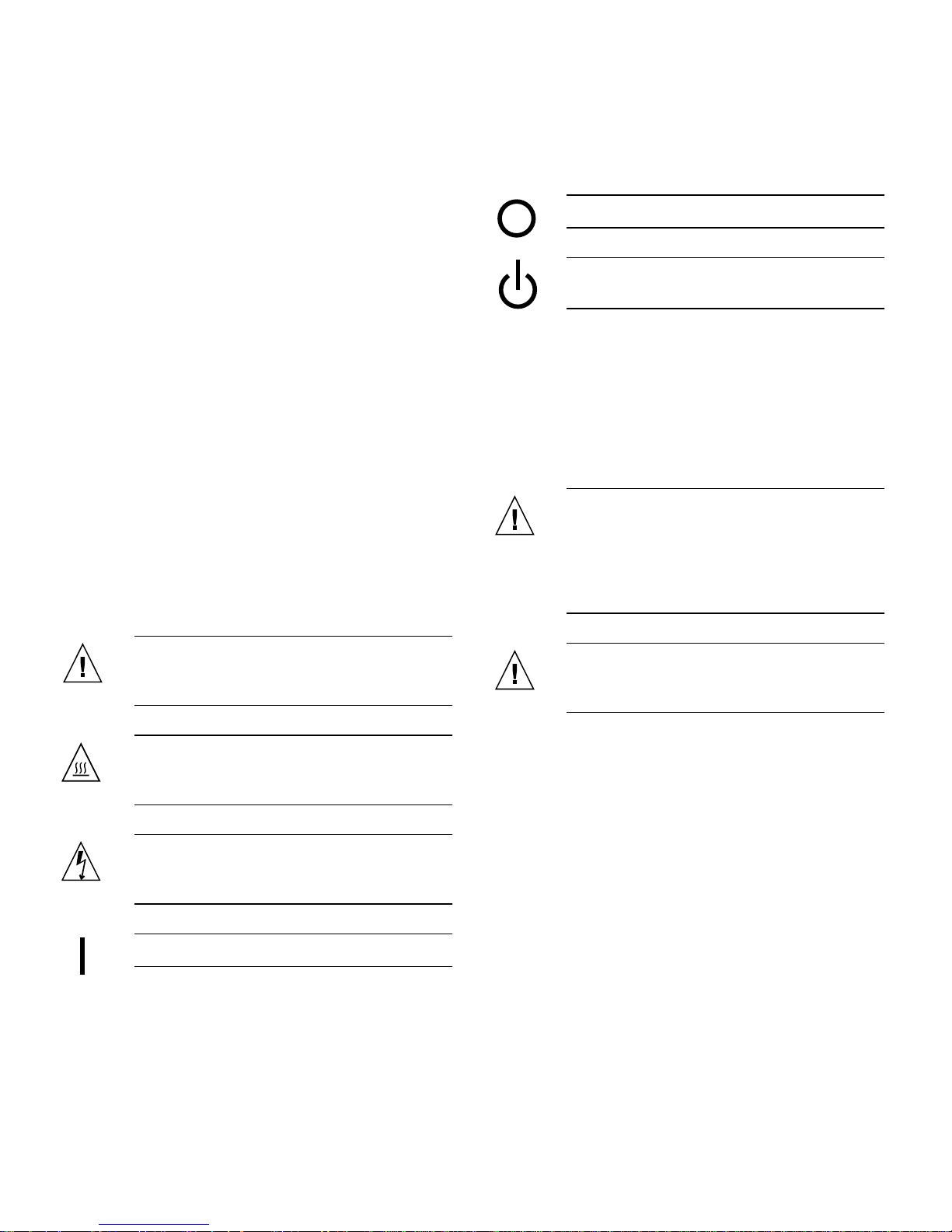
The following symbols may appear in this book:
Depending on the type of power switch your device has,
one of the following symbols may be used:
Off – Removes AC power from the system.
Standby – The On/Standby switch is in the
standby position.
Modifications to Equipment
Do not make mechanical or electrical modifications to the
equipment. Sun Microsystems is not responsible for
regulatory compliance of a modified Sun product.
Placement of a Sun Product
Caution – Do not block or cover the openings
of your Sun product. Never place a Sun
product near a radiator or heat register.
Failure to follow these guidelines can cause
overheating and affect the reliability of your
Sun product.
Caution – There is a risk of personal injury
and equipment damage. Follow the
instructions.
Caution – Hot surface. Avoid contact.
Surfaces are hot and may cause personal
injury if touched.
Caution – Hazardous voltages are present. To
reduce the risk of electric shock and danger to
personal health, follow the instructions.
On – Applies AC power to the system.
Caution – The workplace-dependent noise
level defined in DIN 45 635 Part 1000 must be
70Db(A) or less.
vii
Page 8
SELV Compliance
Safety status of I/O connections comply to SELV
requirements.
Power Cord Connection
Caution – Sun products are designed to work
with single-phase power systems having a
grounded neutral conductor. To reduce the
risk of electric shock, do not plug Sun
products into any other type of power system.
Contact your facilities manager or a qualified
electrician if you are not sure what type of
power is supplied to your building.
Caution – Not all power cords have the same
current ratings. Household extension cords do
not have overload protection and are not
meant for use with computer systems. Do not
use household extension cords with your Sun
product.
Caution – Your Sun product is shipped with a
grounding type (three-wire) power cord. To
reduce the risk of electric shock, always plug
the cord into a grounded power outlet.
The following caution applies only to devices with a
Standby power switch:
Lithium Battery
Caution – On Sun CPU boards, there is a
lithium battery molded into the real-time
clock, SGS No. MK48T59Y, MK48TXXB-XX,
MK48T18-XXXPCZ, M48T59W-XXXPCZ, or
MK48T08. Batteries are not customer
replaceable parts. They may explode if
mishandled. Do not dispose of the battery in
fire. Do not disassemble it or attempt to
recharge it.
Battery Pack
Caution – There is a sealed lead acid battery
in Sun StorEdge A1000 units. Portable Energy
Products No. TLC02V50. There is danger of
explosion if the battery pack is mishandled or
incorrectly replaced. Replace only with the
same type of Sun Microsystems battery pack.
Do not disassemble it or attempt to recharge it
outside the system. Do not dispose of the
battery in fire. Dispose of the battery properly
in accordance with local regulations.
System Unit Cover
You must remove the cover of your Sun computer system
unit to add cards, memory, or internal storage devices. Be
sure to replace the top cover before powering on your
computer system.
Caution – The power switch of this product
functions as a standby type device only. The
power cord serves as the primary disconnect
device for the system. Be sure to plug the
power cord into a grounded power outlet that
is nearby the system and is readily accessible.
Do not connect the power cord when the
power supply has been removed from the
system chassis.
viii Sun StorEdge A1000 and D1000 Installation, Operations, and Service Manual • November 2002
Caution – Do not operate Sun products
without the top cover in place. Failure to take
this precaution may result in personal injury
and system damage.
Page 9
Laser Compliance Notice
Sun products that use laser technology comply with Class 1
laser requirements.
Class 1 Laser Product
Luokan 1 Laserlaite
Klasse 1 Laser Apparat
Laser Klasse 1
CD-ROM
■ N'insérez en aucun cas un objet quelconque dans les
orifices de l'équipement. Des tensions potentiellement
dangereuses risquent d'être présentes dans
l'équipement. Tout objet étranger conducteur risque
de produire un court-circuit pouvant présenter un
risque d'incendie ou de décharge électrique, ou
susceptible d'endommager le matériel.
Symboles
Les symboles suivants peuvent figurer dans cet ouvrage :
Attention – Vous risquez d'endommager le
matériel ou de vous blesser. Observez les
consignes indiquées.
Caution – Use of controls, adjustments, or the
performance of procedures other than those
specified herein may result in hazardous
radiation exposure.
GOST-R Certification Mark
Conformité aux normes de sécurité
Lisezattentivementlasection suivante avant de commencer
la procédure. Le document ci-dessous présente les
consignes de sécurité à respecter au cours de l'installation
d'un produit Sun Microsystems.
Mesures de sécurité
Pour votre protection, observez les mesures de sécurité
suivantes lors de l'installation de l'équipement:
■ Observez tous les avertissements et consignes
indiqués sur l'équipement.
■ Assurez-vous que la tension et la fréquence de votre
source d'alimentation électrique correspondent à la
tension et à la fréquence indiquées sur l'étiquette de la
tension électrique nominale du matériel.
Attention – Surface brûlante. Evitez tout
contact. Ces surfaces sont brûlantes. Vous
risquez de vous blesser si vous les touchez.
Attention – Tensions dangereuses. Pour
réduire les risques de décharge électrique et
de danger physique, observez les consignes
indiquées.
MARCHE – Met le système sous tension
alternative.
Selon le type d'interrupteur marche/arrêt dont votre
appareil est équipé, l'un des symboles suivants sera utilisé :
ARRET – Met le système hors tension
alternative.
VEILLEUSE – L'interrupteur Marche/Veille
est sur la position de veille.
Modifications de l'équipement
N'apportez aucune modification mécanique ou électrique à
l'équipement. Sun Microsystems décline toute
responsabilité quant à la non-conformité éventuelle d'un
produit Sun modifié.
ix
Page 10
Positionnement d’un produit Sun
Attention – N'obstruez ni ne recouvrez les
orifices de votre produit Sun. N'installez
jamais un produit Sun près d'un radiateur ou
d'une source de chaleur. Si vous ne respectez
pas ces consignes, votre produit Sun risque de
surchauffer et son fonctionnement en sera
altéré.
Attention – Votre produit Sun est livré avec
un cordon d'alimentation avec raccord à la
terre (triphasé). Pour réduire les risques de
décharge électrique, branchez toujours ce
cordon sur une source d'alimentation mise à la
terre.
L'avertissement suivant s'applique uniquement aux
systèmes équipés d'un interrupteur Veille :
Attention – Le niveau de bruit inhérent à
l'environnement de travail, tel qu'il est défini
par la norme DIN 45 635 - section 1000, doit
être inférieur ou égal à 70Db(A).
Conformité aux normes SELV
Le niveau de sécurité des connexions E/S est conforme aux
normes SELV.
Raccordement à la source d'alimentation
électrique
Attention – Les produits Sun sont conçus
pour fonctionner avec des systèmes
d'alimentation électrique monophasés avec
prise de terre. Pour réduire les risques de
décharge électrique, ne branchez jamais les
produits Sun sur une source d'alimentation
d'un autre type. Contactez le gérant de votre
bâtiment ou un électricien agréé si vous avez
le moindre doute quant au type d'alimentation
fourni dans votre bâtiment.
Attention – .L'interrupteur d'alimentation de
ce produit fonctionne uniquement comme un
dispositif de mise en veille. Le cordon
d'alimentation constitue le moyen principal de
déconnexion de l'alimentation pour le
système. Assurez-vous de le brancher dans
une prise d'alimentation mise à la terre près
du système et facile d'accès. Ne le branchez
pas lorsque l'alimentation électrique ne se
trouve pas dans le châssis du système.
Pile au lithium
Attention – Sur les cartes UC Sun, une
batterie au lithium a été moulée dans l'horloge
temps réel, de type SGS nº MK48T59Y,
MK48TXXB-XX, MK48T18-XXXPCZ,
M48T59W-XXXPCZ ou MK48T08. Cette
batterie ne doit pas être remplacée par le
client. Elle risque d'exploser en cas de
mauvaise manipulation. Ne la jetez pas au feu.
Ne la démontez pas et ne tentez pas de la
recharger.
Attention – Tous les cordons d'alimentation
n'ont pas la même intensité nominale. Les
cordons d'alimentation à usage domestique ne
sont pas protégés contre les surtensions et ne
sont pas conçus pour être utilisés avec des
ordinateurs. N'utilisez jamais de cordon
d'alimentation à usage domestique avec les
produits Sun.
x Sun StorEdge A1000 and D1000 Installation, Operations, and Service Manual • November 2002
Page 11
Bloc-batterie
CD-ROM
Attention – Les unités Sun StorEdge A1000
contiennent une batterie étanche au plomb.
Produits énergétiques portatifs nº TLC02V50.
Il existe un risque d'explosion si ce bloc
batterie est manipulé ou installé de façon
incorrecte. Ne le remplacez que par un bloc
batterie Sun Microsystems du même type. Ne
le démontez pas et n'essayez pas de le
recharger hors du système. Ne le jetez pas au
feu. Mettez-le au rebut conformément aux
réglementations locales en vigueur.
Couvercle du système
Pour ajouter des cartes, de la mémoire ou des unités de
stockage internes, vous devez démonter le couvercle de
votre système Sun. N'oubliez pas de le remettre en place
avant de mettre le système sous tension.
Attention – Ne travaillez jamais avec un
produit Sun dont le couvercle n'est pas
installé. Si vous ne respectez pas cette
consigne, vous risquez de vous blesser ou
d'endommager le système.
Avis de conformité des appareils laser
Les produits Sun faisant appel à la technologie laser sont
conformes aux normes de sécurité des appareils laser de
classe 1.
Class 1 Laser Product
Luokan 1 Laserlaite
Klasse 1 Laser Apparat
Laser Klasse 1
Attention – .L'utilisation de contrôles et de
réglages ou l'application de procédures autres
que ceux spécifiés dans le présent document
peuvent entraîner une exposition à des
radiations dangereuses.
Notice de qualité GOST-R
Einhaltung sicherheitsbehördlicher
Vorschriften
Lesen Sie diesen Abschnitt sorgfältig durch, bevor Sie mit
dem Arbeitsablauf beginnen. Der folgende Text beschreibt
Sicherheitsmaßnahmen, die bei der Installation von SunProdukten zu beachten sind.
Sicherheitsmaßnahmen
Zu Ihrem eigenen Schutz sollten Sie die folgenden
Sicherheitsmaßnahmen bei der Installation befolgen :
■ Befolgen Sie alle auf die Geräte aufgedruckten
Anweisungen und Warnhinweise.
■ Beachten Sie die Geräteaufschrift, um sicherzustellen,
daß Netzspannung und -frequenz mit der
Gerätespannung und -frequenz übereinstimmen.
■ Führen Sie niemals Gegenstände in die
Geräteöffnungen ein. Es könnten elektrische
Spannungsfelder vorhanden sein. Leitende
Fremdkörper können Kurzschlüsse, Feuer und
elektrische Schläge verursachen oder Ihr Gerät
beschädigen.
Symbole
Die folgenden Symbole werden in diesem Handbuch
verwendet:
xi
Page 12
Achtung – Es besteht die Gefahr der
Verletzung und der Beschädigung des Geräts.
Befolgen Sie die Anweisungen.
Achtung – Heiße Oberfläche. Vermeiden Sie
jede Berührung. Diese Oberflächen sind sehr
heiß und können Verbrennungen verursachen.
Achtung – Elektrisches Spannungsfeld
vorhanden. Befolgen Sie die Anweisungen,
um elektrische Schläge und Verletzungen zu
vermeiden.
Ein – Das System wird mit Wechselstrom
versorgt.
Abhängig von der Art des Stromschalters Ihres Gerätes
wird eventuell eines der folgenden Symbole verwendet:
Aufstellung von Sun-Geräten
Achtung – Geräteöffnungen Ihres SunProdukts dürfen nicht blockiert oder
abgedeckt werden. Sun-Geräte sollten niemals
in der Nähe von Heizkörpern oder
Heißluftklappen aufgestellt werden.
Nichtbeachtung dieser Richtlinien können
Überhitzung verursachen und die
Zuverlässigkeit Ihres Sun-Geräts
beeinträchtigen.
Achtung – Der Geräuschpegel, definiert nach
DIN 45 635 Part 1000, darf am Arbeitsplatz
70dB(A) nicht überschreiten.
SELV-Richtlinien
Alle Ein-/Ausgänge erfüllen die SELV-Anforderungen.
Netzanschlußkabel
Aus– Das System wird nicht mehr mit
Wechselstrom versorgt.
Wartezustand – (Der Ein-/Standby-Schalter
befindet sich in der Standby-Position.
Modifikationen des Geräts
Nehmen Sie keine elektrischen oder mechanischen
Gerätemodifikationen vor. Sun Microsystems ist für die
Einhaltung der Sicherheitsvorschriften von modifizierten
Sun-Produkten nicht haftbar.
Achtung – Sun-Geräte benötigen ein
einphasiges Stromversorgungssystem mit
eingebautem Erdleiter. Schließen Sie SunGeräte nie an ein anderes
Stromversorgungsystem an, um elektrische
Schläge zu vermeiden. Falls Sie die
Spezifikationen der Gebäudestromversorgung
nicht kennen, sollten Sie den
Gebäudeverwalter oder einen qualifizierten
Elektriker konsultieren.
Achtung – Nicht alle Netzanschlußkabel
besitzen die gleiche Stromleitung. Normale
Verlängerungskabel besitzen keinen
Überspannungsschutz und sind nicht für den
Gebrauch mit Computersystemen geeignet.
Benutzen Sie keine
Haushaltverlängerungskabel für Sun-Geräte.
xii Sun StorEdge A1000 and D1000 Installation, Operations, and Service Manual • November 2002
Page 13
Achtung – Ihr Sun-Gerät wurde mit einem
geerdeten (dreiadrigen) Netzanschlußkabel
geliefert. Stecken Sie dieses Kabel immer nur
in eine geerdete Netzsteckdose, um
Kurzschlüsse zu vermeiden.
Der folgende Hinweis bezieht sich nur auf Geräte mit
Standby-Stromschalter:
Achtung – Der Stromschalter dieses Produkts
funktioniert nur als Standby-Gerät. Das
Netzanschlußkabel dient als
Hauptabschaltgerät für das System. Stellen Sie
sicher, daß Sie das Netzanschlußkabel in den
geerdeten Stromausgang in der Nähe des
Systems einstecken. Schließen Sie das
Netzanschlußkabel nicht an, wenn die
Stromzufuhr vom Systemgehäuse entfernt
wurde.
Lithium-Batterie
Batterien
Achtung – Die Geräte Sun StorEdge A1000
enthalten auslaufsichere Bleiakkumulatoren,
Produkt-Nr. TLC02V50 für portable
Stromversorgung. Wenn die Batterien nicht
richtig gehandhabt oder ausgetauscht werden,
besteht Explosionsgefahr. Tauschen Sie
Batterien nur gegen Batterien gleichen Typs
von Sun Microsystems aus. Versuchen Sie
nicht, die Batterien zu entfernen oder
außerhalb des Geräts wiederaufzuladen.
Entsorgen Sie die Batterien nicht im Feuer.
Entsorgen Sie die Batterien ordnungsgemäß
entsprechend den vor Ort geltenden
Vorschriften.
Abdeckung des Systems
Sie müssen die Abdeckung des Sun-Computersystems
entfernen, um Karten, Speicher oder interne Speichergeräte
hinzuzufügen. Stellen Sie sicher, daß Sie die Abdeckung
wieder einsetzen, bevor Sie den Computer einschalten.
Achtung – CPU-Karten von Sun verfügen
über eine Echtzeituhr mit integrierter
Lithiumbatterie, Teile-Nr. MK48T59Y,
MK48TXXB-XX, MK48T18-XXXPCZ,
M48T59W-XXXPCZ oder MK48T08.
Batterien sollten nicht vom Kunden
ausgetauscht werden. Sie können bei falscher
Handhabung explodieren. Entsorgen Sie die
Batterien nicht im Feuer. Entfernen Sie sie
nicht und versuchen Sie auch nicht, sie
wiederaufzuladen.
Achtung – Sun-Geräte dürfen nicht ohne
Abdeckung in Gebrauch genommen werden.
Nichtbeachtung dieses Warnhinweises kann
Verletzungen oder Systembeschädigungen zur
Folge haben.
Laserrichtlinien
Alle Sun-Produkte, die Lasertechnologie nutzen, erfüllen
die Laserrichtlinien der Klasse 1.
Class 1 Laser Product
Luokan 1 Laserlaite
Klasse 1 Laser Apparat
Laser Klasse 1
xiii
Page 14
CD-ROM
Achtung – Die Verwendung von anderen
Steuerungen und Einstellungen oder die
Durchführung von Arbeitsabläufen, die von
den hier beschriebenen abweichen, können
gefährliche Strahlungen zur Folge haben.
Verbandsmarke GOST-R
Normativas de seguridad
Lea esta sección antes de llevar a cabo cualquier
procedimiento. El texto que aparece a continuación explica
las medidas de seguridad que deben tomarse durante la
instalación de un producto Sun Microsystems.
Precaución – Superficie caliente. Evite todo
contacto. Las superficies están calientes y
pueden causar lesiones personales si se tocan.
Precaución – Riesgo de voltajes peligrosos.
Para reducir el riesgo de descargas eléctricas y
de daños en la salud de las personas, siga las
instrucciones.
Encendido – Proporciona alimentación de CA
al sistema.
Según el tipo de interruptor de alimentación del que
disponga el dispositivo, se utilizará uno de los símbolos
siguientes:
Apagado – Corta la alimentación de CA del
sistema.
Medidas de seguridad
Por su propia seguridad, tome las medidas de seguridad
siguientes al instalar el equipo:
■ Siga todas los avisos y las instrucciones que aparecen
impresas en el equipo.
■ Cerciórese de que el voltaje y la frecuencia de la
fuente de alimentación coinciden con el voltaje y
frecuencia indicados en la etiqueta de clasificación
eléctrica del equipo.
■ No introduzca objetos de ningún tipo a través de las
aberturas del equipo. Dentro pueden darse voltajes
peligrosos. Los objetos conductores extraños podrían
producir un cortocircuito y, en consecuencia, fuego,
descargas eléctricas o daños en el equipo.
Símbolos
Los símbolos siguientes pueden aparecer en este manual:
Precaución – Existe el riesgo de que se
produzcan lesiones personales y daños en el
equipo. Siga las instrucciones.
Espera – El interruptor de encendido/espera
está en la posición de espera.
Modificaciones en el equipo
No realice modificaciones mecánicas ni eléctricas en el
equipo. Sun Microsystems no se hará responsable del
cumplimiento de las normas en el caso de un producto Sun
que ha sido modificado.
Lugar y colocación de un producto Sun
Precaución – No obstruya ni tape las rejillas
del producto Sun. Nunca coloque un producto
Sun cerca de radiadores o fuentes de calor. El
incumplimiento de estas directrices puede
causar un recalentamiento y repercutir en la
fiabilidad del producto Sun.
Precaución – El nivel de ruido en el lugar de
trabajo, definido en el apartado 1000 de DIN
45 635, debe ser 70 Db (A) o inferior.
xiv Sun StorEdge A1000 and D1000 Installation, Operations, and Service Manual • November 2002
Page 15
Cumplimiento de las normas SELV
Las condiciones de seguridad de las conexiones de E/S
cumplen las normas SELV.
Conexión del cable de alimentación
Precaución – Los productos Sun han sido
diseñados para funcionar con sistemas de
alimentación monofásicos que tengan un
conductor neutral a tierra. Para reducir el
riesgo de descargas eléctricas, no enchufe
ningún producto Sun a otro tipo de sistema de
alimentación. Si no está seguro del tipo de
alimentación del que se dispone en el edificio,
póngase en contacto con el encargado de las
instalaciones o con un electricista cualificado.
Precaución – No todos los cables de
alimentación tienen la misma clasificación de
corriente. Los cables de prolongación
domésticos no ofrecen protección frente a
sobrecargas y no están diseñados para ser
utilizados con sistemas informáticos. No
utilice cables de prolongación domésticos con
el producto Sun.
Precaución – El interruptor de alimentación
del producto funciona como dispositivo de
espera solamente. El cable de alimentación
actúa como el dispositivo de desconexión
primario del sistema. Cerciórese de enchufar
el cable de alimentación a una toma de
corriente con conexión a tierra situada cerca
del sistema y a la que se pueda acceder con
facilidad. No conecte el cable de alimentación
cuando se haya quitado la fuente de
alimentación del bastidor del sistema.
Batería de litio
Precaución – En la placa CPU de los
productos Sun, hay una batería de litio
incorporada en el reloj en tiempo real, SGS
núm. MK48T59Y, MK48TXXB-XX, MK48T18XXXPCZ, M48T59W-XXXPCZo MK48T08. Los
usuarios no deben cambiar las baterías.
Podrían estallar si no se utilizan
adecuadamente. No arroje la batería al fuego.
No la desmonte ni intente recargarla.
Precaución – El producto Sun se suministra
con un cable de alimentación (de tres hilos)
con conexión a tierra. Para reducir el riesgo de
descargas eléctricas, enchufe siempre el cable
a una toma de corriente con conexión a tierra.
La precaución siguiente sólo se aplica a aquellos
dispositivos que posean un interruptor de alimentación de
espera:
Paquete de baterías
Precaución – Las unidadesSun StorEdge
A1000 contienen una batería de plomo sellada,
Productos eléctricos portátiles núm.
TLC02V50. Existe el riesgo de explosión si el
paquete de baterías no se utiliza
correctamente o se sustituye de forma
incorrecta. Sustitúyalo sólo por el mismo tipo
de paquete de baterías de Sun Microsystems.
No lo desmote o intente recargarlo fuera del
sistema. No arroje la batería al fuego.
Deshágase de las baterías correctamente
siguiendo las normas locales vigentes.
xv
Page 16
Cubierta de la unidad del sistema
Deberetirar la cubierta de la unidad del sistema informático
Sun para añadir tarjetas, memoria o dispositivos de
almacenamiento internos. Asegúrese de volver a colocar la
cubierta superior antes de encender el equipo.
Precaución – No ponga en funcionamiento
los productos Sun sin que la cubierta superior
se encuentre instalada. De lo contrario,
podrían producirse lesiones personales o
daños en el sistema.
Nordic Lithium Battery Cautions
Norge
ADVARSEL – Litiumbatteri —
Eksplosjonsfare.Ved utskifting benyttes kun
batteri som anbefalt av apparatfabrikanten.
Brukt batteri returneres apparatleverandøren.
Sverige
Aviso de cumplimiento de las normas para
láser
LosproductosSun que utilizan tecnología láser cumplen los
requisitos para láser de Clase 1.
Class 1 Laser Product
Luokan 1 Laserlaite
Klasse 1 Laser Apparat
Laser Klasse 1
CD-ROM
Precaución – La utilización de controles,
ajustes o la realización de los procedimientos
distintos a los especificados en el presente
documento podrían provocar la exposición a
radiaciones peligrosas.
VARNING – Explosionsfara vid felaktigt
batteribyte. Använd samma batterityp eller en
ekvivalent typ som rekommenderas av
apparattillverkaren. Kassera använt batteri
enligt fabrikantens instruktion.
Danmark
ADVARSEL! – Litiumbatteri —
Eksplosionsfare ved fejlagtig håndtering.
Udskiftning må kun ske med batteri af samme
fabrikat og type. Levér det brugte batteri
tilbage til leverandøren.
Suomi
VAROITUS – Paristo voi räjähtää, jos se on
virheellisesti asennettu. Vaihda paristo
ainoastaan laitevalmistajan suosittelemaan
tyyppiin. Hävitä käytetty paristo valmistajan
ohjeiden mukaisesti.
Certificación GOST-R
xvi Sun StorEdge A1000 and D1000 Installation, Operations, and Service Manual • November 2002
Page 17

Contents
Declaration of Conformity vi
Contents xvii
Preface xxi
Using UNIX Commands xxi
Typographic Conventions xxii
Shell Prompts xxii
Related Documentation xxiii
Accessing Sun Documentation xxiii
Sun Welcomes Your Comments xxiii
1. Getting Started 1
SCSI Host Adapters 1
Before You Begin 1
Sun StorEdge A1000 Configurations 2
Sun StorEdge D1000 Configurations 3
Preparing and Installing the System 5
Installing the System 5
2. Product Overview 7
Contents xvii
Page 18

System Hardware 7
Sun StorEdge A1000 Hardware
RAID System 7
Components at the Front of the Unit 8
Components at the Back of the Unit 9
Power Modules 11
Cooling System 12
Disk Drives 12
Dummy Drives 12
Sun StorEdge A1000 Hardware RAID
Controller Module 13
Sun StorEdge A1000 Software 13
The Sun StorEdge D1000 Unit 14
Components at the Front of the Unit 14
Components at the Back of the Unit 15
Power Modules 18
Cooling System 18
Disk Drives 19
Dummy Drives 19
Sun StorEdge D1000 Software Considerations 20
3. Removing and Replacing Components 21
Hot-pluggable Parts 21
Replaceable with Power Off 21
Replacing Hot-Pluggable Parts 22
Hard Disk Drives 22
Cooling Canisters 23
Power Supplies 24
Replacing Parts with the Power Off 26
Controller Board 26
xviii Sun StorEdge A1000 and D1000 Installation, Operations, and Service Manual • November 2002
Page 19

Battery (A1000 Only) 28
SIMM Upgrade Procedure (A1000 only) 30
A. System Specifications 33
Physical Specifications 33
Electrical Specifications 33
Environmental Specifications 35
Contents xix
Page 20

xx Sun StorEdge A1000 and D1000 Installation, Operations, and Service Manual • November 2002
Page 21

Preface
The Sun™ StorEdge™ A1000 and D1000 Installation, Operations, and Service Manual
provides installation and configuration information and service procedures to
customers and service personnel for the Sun StorEdge A1000 and D1000 systems.
These instructions are designed for an experienced system administrator.
Using UNIX Commands
This document might not contain information on basic UNIX®commands and
procedures such as shutting down the system, booting the system, and configuring
devices.
See one or more of the following for this information:
■ Solaris Handbook for Sun Peripherals
■ AnswerBook2
■ Other software documentation that you received with your system
™
online documentation for the Solaris™operating environment
xxi
Page 22

Typographic Conventions
Typeface
AaBbCc123 The names of commands, files,
AaBbCc123
AaBbCc123 Book titles, new words or terms,
* The settings on your browser might differ from these settings.
*
Meaning Examples
Edit your.login file.
and directories; on-screen
computer output
What you type, when contrasted
with on-screen computer output
words to be emphasized.
Replace command-line variables
with real names or values.
Use ls -a to list all files.
% You have mail.
% su
Password:
Read Chapter 6 in the User’s Guide.
These are called class options.
You must be superuser to do this.
To delete a file, type rm filename.
Shell Prompts
Shell Prompt
C shell machine-name%
C shell superuser machine-name#
Bourne shell and Korn shell $
Bourne shell and Korn shell superuser #
.
xxii Sun StorEdge A1000 and D1000 Installation, Operations, and Service Manual • November 2002
Page 23

Related Documentation
Application Title Part Number
RAID Installation RAID Manager 6.1.1 Installation and
Support Guide for Solaris
RAID User Guide RAID Manager 6.1.1 User’s Guide 805-4057
RAID Release Notes Sun StorEdge A1000 Product Release
Notes
Hot-plug Instructions Sun StorEdge D1000 Storage Guide 805-4013
805-4058
805-3656
Accessing Sun Documentation
You can view, print, or purchase a broad selection of Sun documentation, including
localized versions, at:
http://www.sun.com/documentation
Sun Welcomes Your Comments
Sun is interested in improving its documentation and welcomes your comments and
suggestions. You can email your comments to Sun at:
Please include the part number (805-2624-11) of your document in the subject line of
your email.
Preface xxiii
Page 24

xxiv Sun StorEdge A1000 and D1000 Installation, Operations, and Service Manual • November 2002
Page 25

CHAPTER
1
Getting Started
The Sun StorEdge A1000 and D1000 systems are made up of a chassis, dual
power supplies, dual cooling canisters, the controller module and from 4 to 12
hot-pluggable, UltraSCSI hard disk drives. Both the A1000 and D1000 units may
be used on the desktop.
This chapter provides instructions on how to prepare the area, connect the
cables and power on the system.
SCSI Host Adapters
You must use one of two host adapter boards available from Sun, depending on
your host system’s requirements:
■ For SBus based hosts — SBus to differential UltraSCSI adapter, UDWIS/S Model
X1065A
■ For PCI based hosts — PCI to dual differential UltraSCSI adapter, Model X6541A
Before You Begin
Make sure you do the following before you install the system:
1. Read the Product Notes, if any, for updated product information.
Information contained in the Product Notes may affect your installation.
1
Page 26
2. Prepare the site for the installation, including determining site power and sizing
requirements.
Refer to Appendix A for power, size, and weight statistics.
3. Halt operations and power off your host system.
Refer to your host system documentation for instructions on powering off the
system.
4. Install either an SBus wide intelligent UltraSCSI differential (UDWIS/S) or a PCI
adapter card into your host system.
Refer to the documentation that shipped with the adapter card for installation
instructions.
5. Have other documents available during the installation.
■ Software documents (available on the system CD)
6. Decide which configuration to use.
Sun StorEdge A1000 Configurations
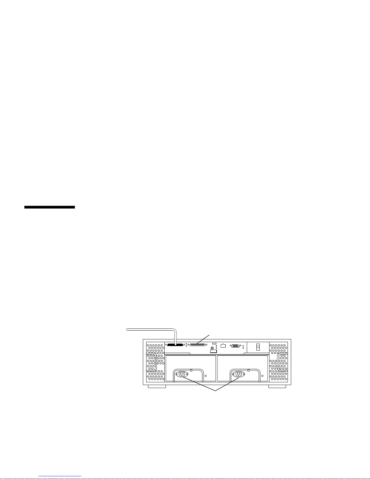
You can use the Sun StorEdge A1000 Hardware RAID controller as a single unit
connected to one or more hosts, or connect up to ten units together in a chain. For
optimal performance, chain only three Sun StorEdge A1000 units together.
See
FIGURE 1-1 and FIGURE 1-2.
SCSI Connectors
SCSI Cable to Host
FIGURE 1-1 Single Sun StorEdge A1000 Connected to a Single Host
IN/OUT
IN/OUT
Terminator
AC Power Connectors
2 Sun StorEdge A1000 and D1000 Installation, Operations, and Service Manual • November 2002
Page 27
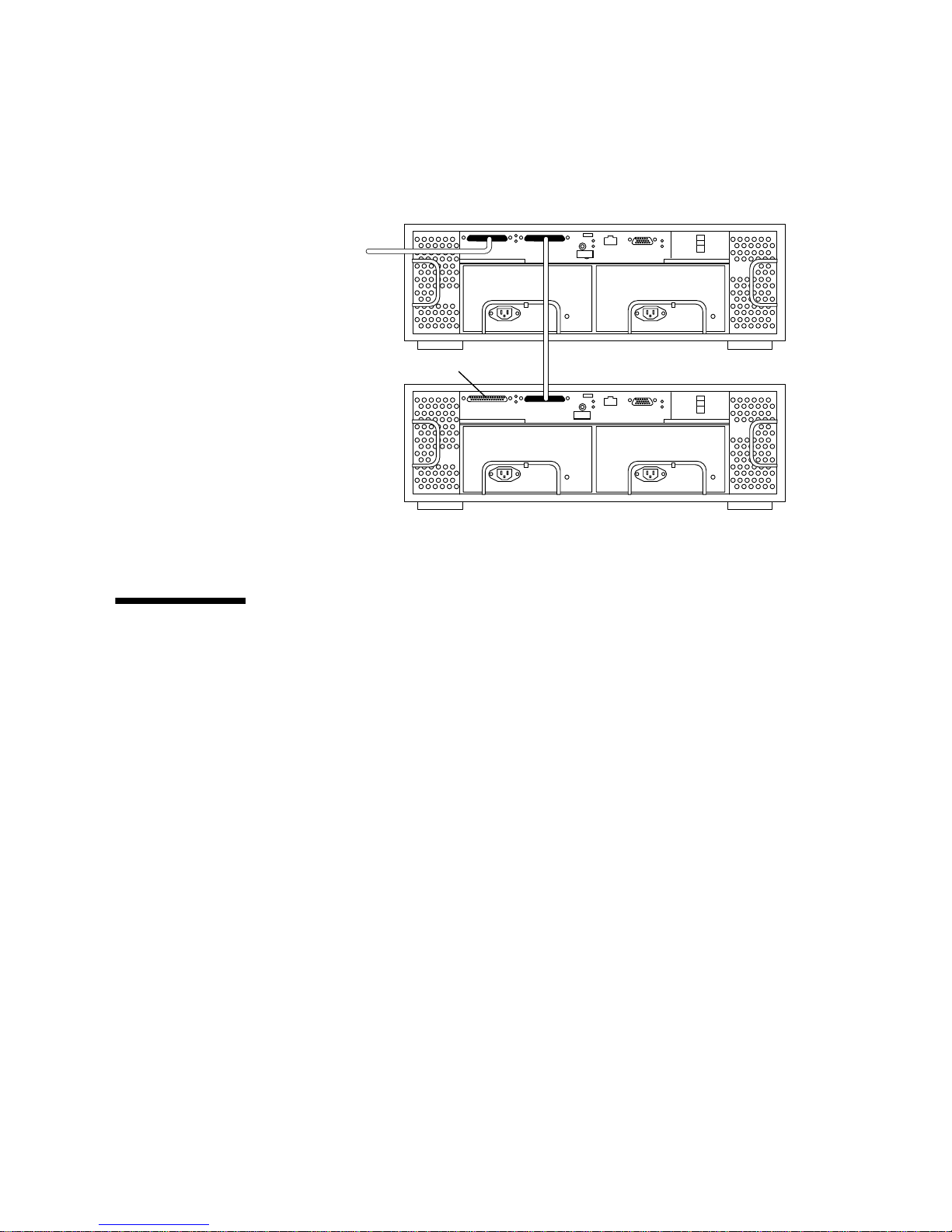
SCSI Connectors
IN/OUT
SCSI Cable to Host
Terminator
FIGURE 1-2 A Sun StorEdge A1000 in a Chained Configuration
IN/OUT
Sun StorEdge D1000 Configurations
You can use the Sun StorEdge D1000 unit in several different configurations.
■ As a single box of disks attached to a single host ( FIGURE 1-3)
Chapter 1 Getting Started 3
Page 28
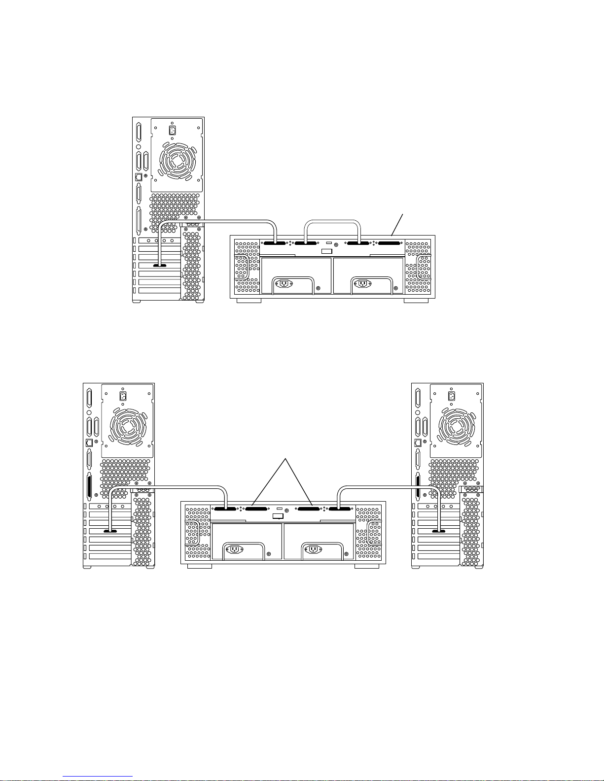
Terminator
FIGURE 1-3 A Single Sun StorEdge D1000 Connected to a Single Host
Terminators
FIGURE 1-4 A Single Sun StorEdge D1000 Split Between Two Hosts
■ A single unit split between two hosts, where each host has access to half the disks
(
FIGURE 1-4).
4 Sun StorEdge A1000 and D1000 Installation, Operations, and Service Manual • November 2002
Page 29
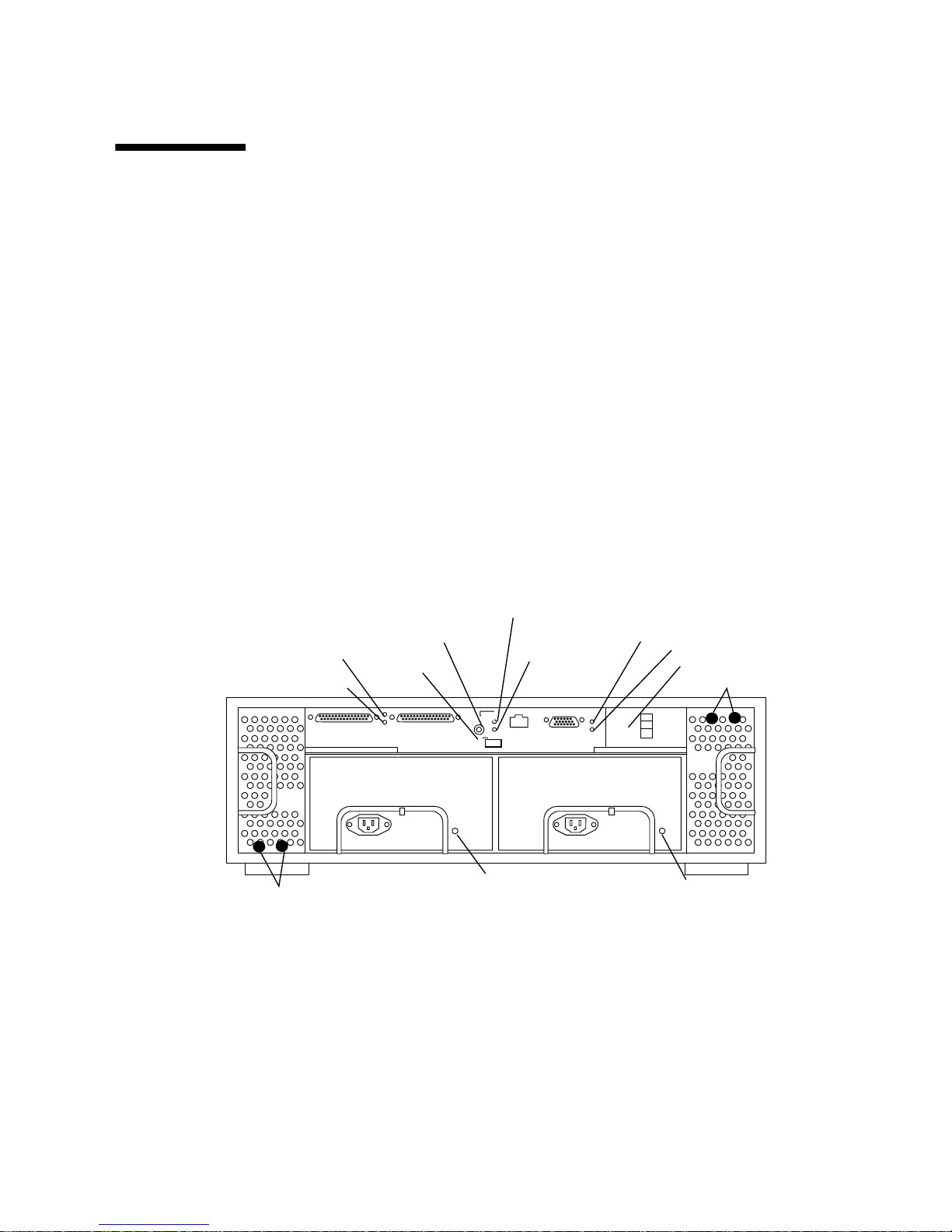
Preparing and Installing the System
You must perform the following tasks to prepare and install your Sun StorEdge
A1000 or D1000 system.
1. Set up your Sun StorEdge A1000 or D1000 with the mounting hardware, if any,
that came with your system.
2. Determine which SCSI target addresses are available on your host system.
Refer to the Solaris Handbook for SMCC Peripherals available on the Solaris AnswerBook
on-line documentation for information on how to determine which SCSI target IDs
are already in use.
Installing the System
1. Set the target addresses for your system (A1000 hardware RAID controller).
Temperature Fault
Battery Fault
Battery Charge
Battery
Blower Status 3 and 4
Controller Fault
Controller Active
SCSI ID Switch
Power Switch
Controller Power
IN/OUT
IN/OUT
Power
Blower Status 1 and 2
Supply
Status
Note: x = 10Base-T Ethernet (reserved for factory or future use)
y = RS232C port(reserved for factory or future use)
FIGURE 1-5 Sun StorEdge A1000 Rear View
2. Set the option switch (D1000).
FIGURE 2-7 or FIGURE 2-8 for split box configurations.
See
y
x
Power
Supply
Status
Chapter 1 Getting Started 5
Page 30
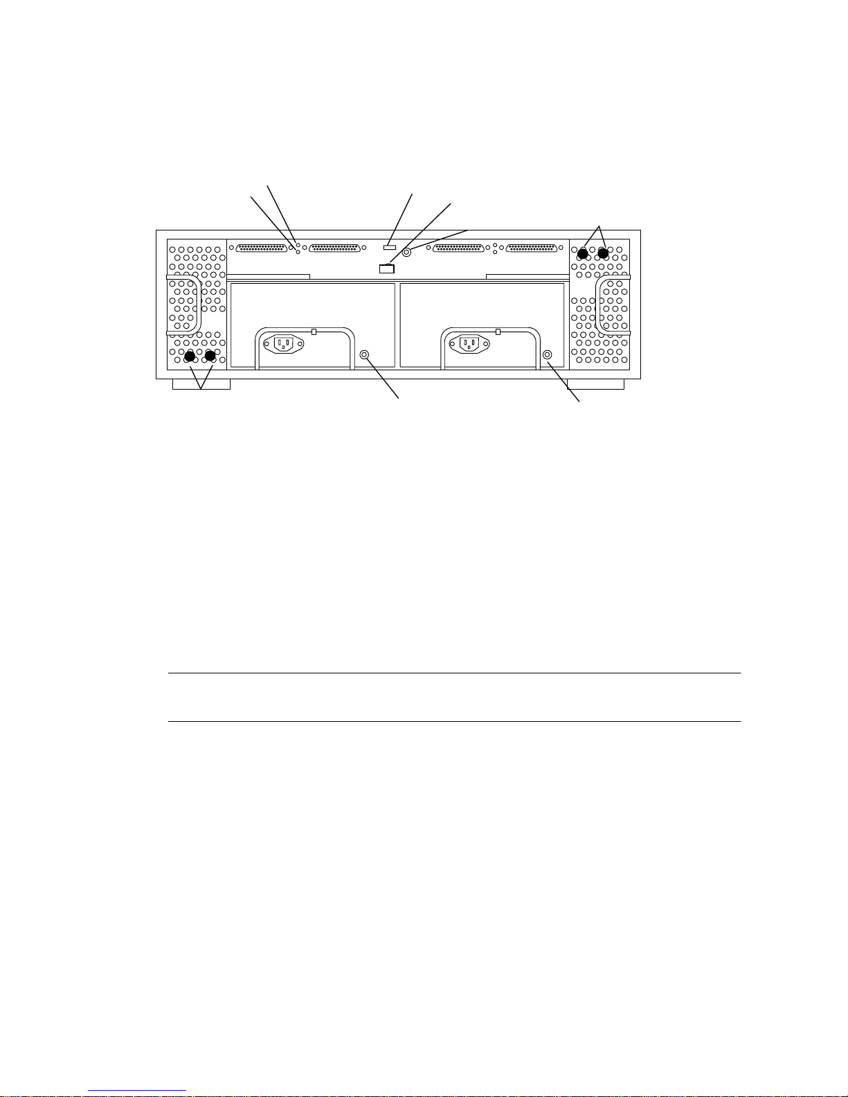
Temperature Fault
Controller Power
Option Switch
Power Switch
Module ID
Blower Status 3and 4
IN/OUT-1 IN/OUT-1
Blower Status 1 and 2
Power
Supply
Status
FIGURE 1-6 Sun StorEdge D1000 Rear View
IN/OUT -2
IN/OUT -2
Power
Supply
Status
3. Connect the cables and power cords.
Use only UltraSCSI cables.
4. Install one or more terminators, depending on the configuration you have chosen.
5. Turn on the power to the Sun StorEdge A1000 or D1000 system and the host
system.
6. Install any additional software.
Note – For the Sun StorEdge A1000 you must use RAID Manager 6.1.1 (or better),
which comes with your unit.
6 Sun StorEdge A1000 and D1000 Installation, Operations, and Service Manual • November 2002
Page 31

CHAPTER
2
Product Overview
This chapter describes the controller module and other system components,
except the hard drives. For information on the drives, refer to the documents
that you received with them.
System Hardware
The system comes in two basic configurations:
■ A1000 unit — Hardware RAID controller based configuration
■ D1000 unit — “Just a Bunch of Disks” (JBOD) configuration
Sun StorEdge A1000Hardware
RAID System
The system chassis houses several removable devices, including:
■ Sun StorEdge A1000 Hardware RAID Controller Module
■ Two power supplies
■ Battery
■ Dual cooling canisters
■ Disk drives
7
Page 32
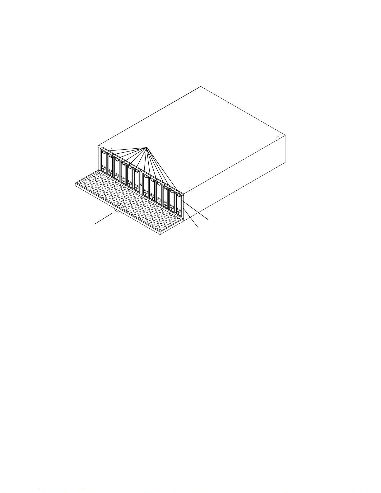
Components at the Front of the Unit
Back
Drive LEDs
Front
Door Latch
System Power LED
System Summary Fault LED
FIGURE 2-1 Sun StorEdge A1000 Front — An Example of a Twelve 1-inch Drive System
Front Door
The lockable front door opens to allow access to the hard disk drives. The door keys
are in the ship kit pouch.
The system backplane for the hard disk drives can accept up to eight 1.6-inch drives
or twelve 1-inch drives.
LEDs on the Front (FIGURE 2-1)
■ System Power LED: lights green when the system is powered on.
■ System Summary Fault LED: lights amber when a system component, such as a
disk, cooling canister or a power supply, needs service.
■ Each slot for a hard disk drive has a two-color LED above the disk drive. The
LED:
■ Remains unlit when no drive is in the slot
■ Lights green when the drive is present but not active
8 Sun StorEdge A1000 and D1000 Installation, Operations, and Service Manual • November 2002
Page 33
■ Flashes green when the drive in the slot is active
■ Lights amber when the drive has been marked as failed by the A1000 controller
Components at the Back of the Unit
At the rear of the A1000 system are two power supplies, two cooling canisters
with two blowers each, a battery, two 68-pin connectors for the host SCSI bus, a
SCSI ID switch and a locking power switch.
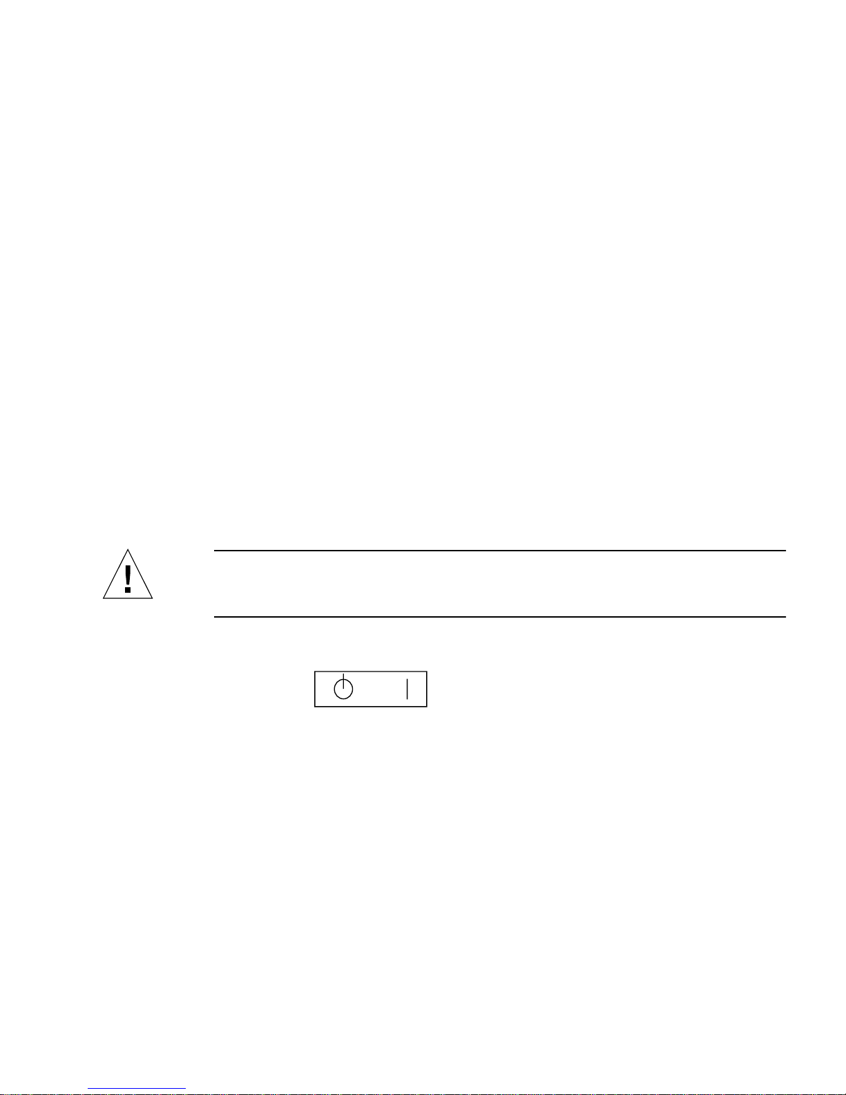
Power Switch
The Sun StorEdge A1000 system has one rocker power switch to control both power
supplies (
■ Right — Momentary ON position |, either or both power supplies provide power
to the system
■ Center — Neutral position, when the switch is released from the ON position, the
switch settles into the Neutral position and the power supplies remain on.
■ Left — Standby Position, neither power supply provides power.
FIGURE 2-3).
Caution – Turning the power switch to the Standby position does not completely
cut off power to the system. AC input to each power supply is still connected to the
electrical outlet until the power cord is unplugged.
Standby
Neutral
FIGURE 2-2 Power Switch
Momentary On
SCSI ID Switch
The A1000 configuration has one SCSI ID switch for selecting the controller SCSI
target address, from 0 to 15. Different SCSI target IDs are required if you have two or
more A1000 systems daisy-chained together.
Chapter 2 Product Overview 9
Page 34
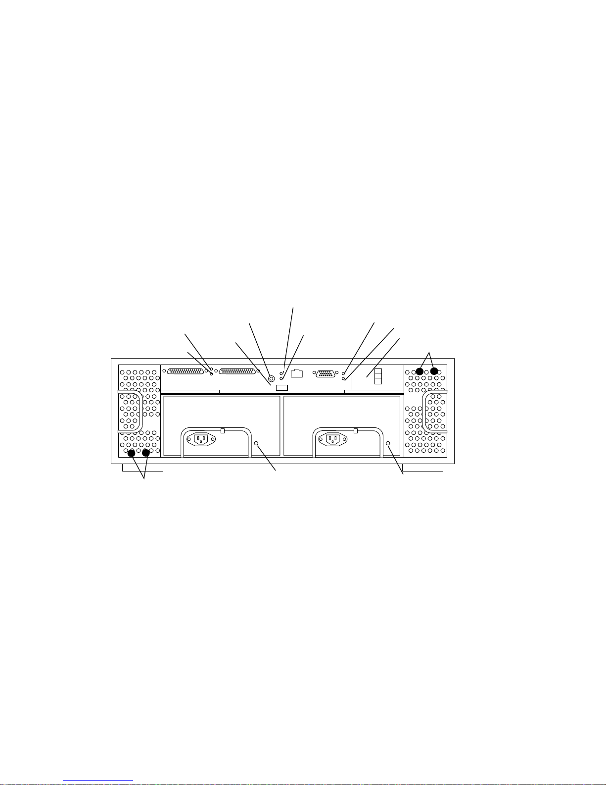
Battery
The Sun StorEdge A1000 system has a data cache hold-up battery in the hardware
RAID controller board. During a power outage, a properly charged battery will
maintain electrical power to the controller’s data cache memory for up to three days.
Thus, all data stored in data cache memory will be preserved as long as the battery
can sustain power to the data cache memory. The battery is self recharging with the
power on and is replaceable, after a two-year life, without removing any other
modules.
■ The “Caution” label contains weight and length information for safe removal and
and installation purposes.
■ The “Battery Support Information” label contains three dates for maintenance
purposes.
Temperature Fault
Battery Fault
Battery Charge
Battery Canister
Blower Status 3 and 4
Controller Fault
Controller Active
SCSI ID Switch
Power Switch
Controller Power
IN/OUT
Blower Status 1 and 2
IN/OUT
Power
Supply
Status
y
x
Power
Supply
Status
Note: x = 10Base-T Ethernet (reserved for factory or future use)
y = RS232C port(reserved for factory or future use)
FIGURE 2-3 Sun StorEdge A1000 Rear View
LEDs on the Back
■ Power Supply Status, one two-color LED on each power module:
■ Lights green when the power supply is operating properly
■ Lights amber when the power supply has failed but the other power supply is
operating normally, or if the power cord is unplugged
■ Off if both power supplies are not plugged in or have failed
10 Sun StorEdge A1000 and D1000 Installation, Operations, and Service Manual • November 2002
Page 35

■ Cooling Canister Status, 2 two-color LEDs on each cooling canister (one for each
blower):
■ lights green when the individual blower is operating properly
■ lights amber when the individual blower has failed
■ Off when the cooling canister is not inserted
The A1000 controller has 6 single-color LEDS:
■ Controller Fault
■ Lights amber when a controller fault is detected
■ Off when the controller functions normally
■ Controller Activity :
■ Lights green when the controller is active
■ Off when the controller is inactive
■ Temperature Fault
■ Lights amber when the controller board is over normal operating temperature
■ Off when the controller temperature is normal
■ Controller Power
■ Lights green when the controller board is powered on
■ Off when it receives no power
■ Battery Fault
■ Lights amber when there is no battery or there is a battery fault
■ Off when the battery is fully charged
■ Battery Charge:
■ Lights solid green when the battery is fast charging
■ Flashes green when the battery is in the pre-charging phase
■ Off when the battery is not charging
Power Modules
The Sun StorEdge A1000 system has two hot-pluggable and interchangeable power
supplies. The two power supplies provide power to the internal components,
converting incoming AC voltage to DC voltages. These are redundant power
supplies—one power supply will maintain electrical power to the system if the other
power supply fails. Both power supplies are removable canisters that slide into one
of two slots on the back of the system. Each canister has a locking handle, a power
status LED, and an AC power cord connector.
Chapter 2 Product Overview 11
Page 36
Cooling System
The Sun StorEdge A1000 system has two cooling canisters. Each contains two
blowers. The cooling canisters are hot-pluggable and interchangeable.
The Sun StorEdge A1000 system can operate fully cooled with three of the four
blowers functioning. If two blowers fail, the remaining two can maintain the system
in a 30C environment, but the reliability of the components may be affected.
The blower speeds are variable and increase their speed to counteract unusual
cooling conditions, such as one failed blower or increased internal temperature.
Caution – Do not operate the system for extended periods with one or more
redundant modules not installed. The cooling system will become inefficient.
Disk Drives
For specific information about the drives installed in your system, see the separate
drive documentation that comes with your system.
Disk Drive Address ID Assignments
Each drive bay is assigned an address ID. T
Sun StorEdge A1000
In a Sun StorEdge A1000, the RAID Manager software identifies the drives as
follows:
■ 8-drive system
[2,0] [2,1] [2,2] [2,3] and [1,0] [1,1] [1,2] [1,3]
■ 12-drive system (default)
[2,0] [2,1] [2,2] [2,3] [2,4] [2,5] and [1,0] [1,1] [1,2] [1,3] [1,4] [1,5]
Dummy Drives
If you ordered a system with less than the maximum number of disk drives, dummy
drives fill the holes for the emply slots. The dummy drives are air baffles; they allow
the system to maintain maximum cooling. If any slot does not contain a disk drive,
you must fill the slot with a dummy drive so the unit will cool properly.
12 Sun StorEdge A1000 and D1000 Installation, Operations, and Service Manual • November 2002
Page 37

Sun StorEdge A1000 Hardware RAID
Controller Module
The Sun StorEdge A1000 hardware RAID controller module is a compact unit
designed to provide high-performance disk array management services. The
controller module supports dual SCSI hosts on a 16-bit SCSI-2 bus. There are 2 SCSI
controllers inside the controller module that manage data distribution and storage
for up to 12 disk drives. The controllers perform system status and fault detection
functions as well. RAID Manager allows the user to reset the disk array in different
RAID configurations.
The Sun StorEdge A1000 controller module comes with two 4MB Single Inline
Memory Modules (SIMMs) for program memory and two 8MB SIMMs for data
cache memory installed and two UltraSCSI connectors (68-pin) for the host
connection. Data cache memory is a memory buffer on the controller used to support
the Write Cache feature of RAID Manager, the disk array management software.
The standard configuration contains 24 MB of DRAM, upgradable to 80 MB DRAM.
See “SIMM Upgrade Procedure (A1000 only)” on page 30.
Sun StorEdge A1000 Software
The firmware for your Sun StorEdge A1000 Hardware RAID Controller is installed
at the factory. The RAID Manager software is shipped with your system and runs on
the host system. It allows you to configure the system for RAID functionality.
Chapter 2 Product Overview 13
Page 38
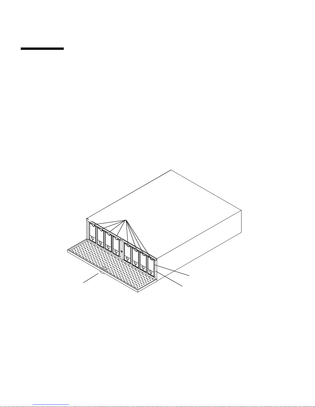
The Sun StorEdge D1000 Unit
The system chassis houses several removable devices, including:
■ D1000 controller interface board, providing two independent USCSI bus
connections
■ Dual power supplies
■ Dual cooling canisters
■ Disk drives
Components at the Front of the Unit
Drive LEDs
System Power LED
Door Latch
FIGURE 2-4 Sun StorEdge D1000 Front — An Example of a Eight 1.6-inch Drive System
(Reserved)
Front Door
The lockable front door opens to allow access to the hard disk drives. The door keys
are in the ship kit pouch.
14 Sun StorEdge A1000 and D1000 Installation, Operations, and Service Manual • November 2002
Page 39
The system backplane for the hard disk drives can accept up to eight 1.6-inch drives
or twelve 1-inch drives.
LEDs on the Front
■ System Power LED: lights green when the system is powered on.
■ Each slot for a hard disk drive has a two-color LED above the disk drive. The
LED:
■ Remains unlit when no drive is in the slot
■ Lights green when the drive is present but not active
■ Flashes green when the drive in the slot is active
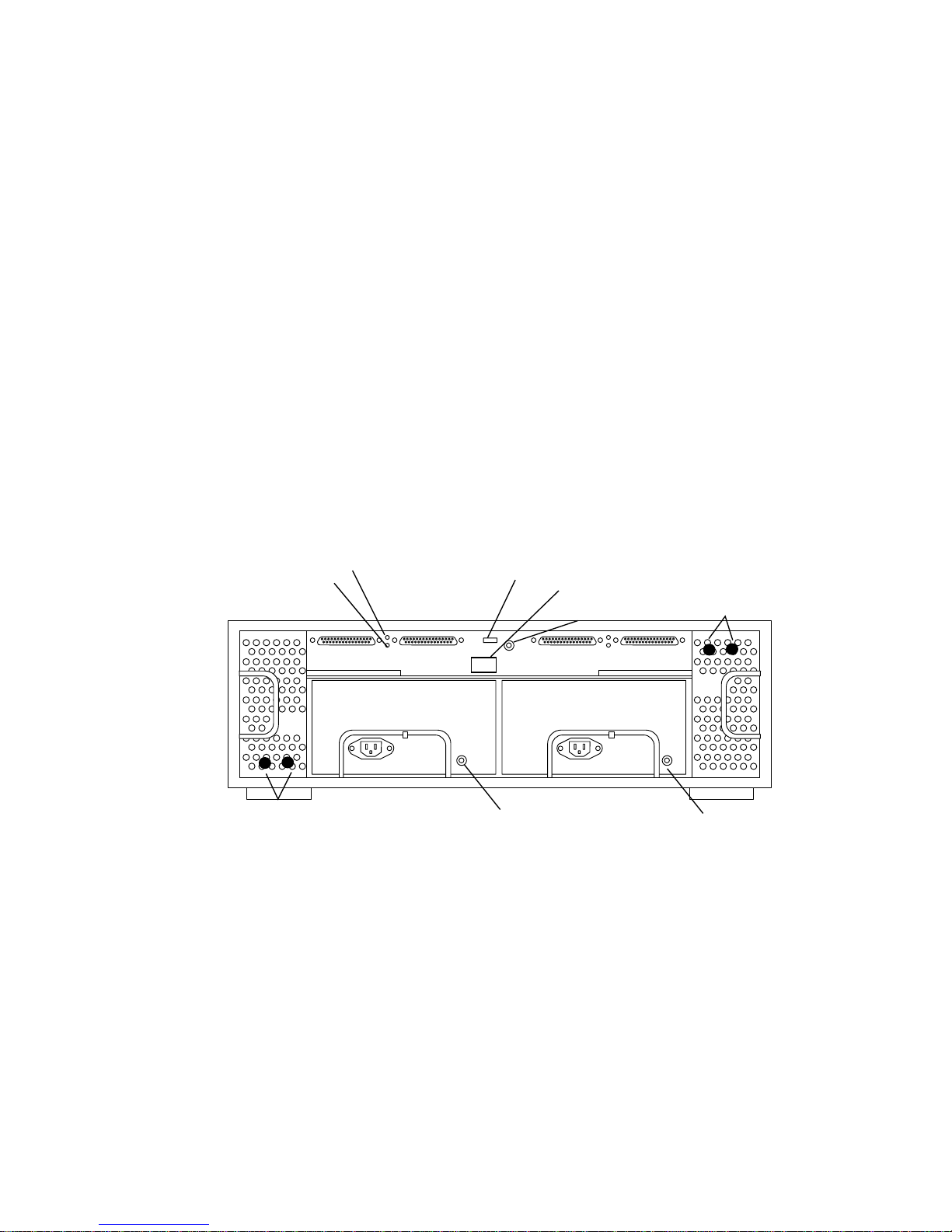
Components at the Back of the Unit
Temperature Fault
Controller Power
IN/OUT-1 IN/OUT-1
Blower Status 1 and 2
FIGURE 2-5 Sun StorEdge D1000 Rear View
Option Switch
IN/OUT -2
Power
Supply
Status
Power Switch
Reserved
IN/OUT -2
Blower Status 3and 4
Power
Supply
Status
At the rear of the D1000 system are two power supplies, two cooling canisters
with two blowers each, four 68-pin connectors for the host SCSI buses, and a
rocker power switch.
Chapter 2 Product Overview 15
Page 40
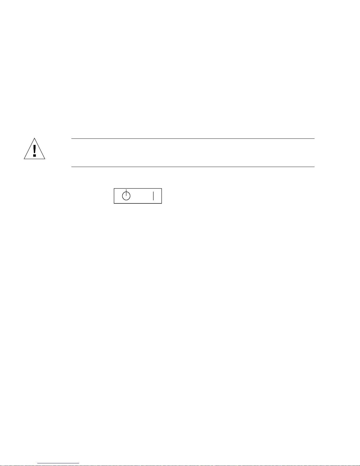
Power Switch
The Sun StorEdge D1000 system has one rocker power switch to control both power
supplies (
■ Right — Momentary ON position |, either or both power supplies provide power
to the system
■ Center — Neutral position, when the switch is released from the ON position, the
switch settles into the Neutral position and the power supplies remain on.
■ Left — Standby Position, neither power supply provides power.
Caution – Turning the power switch to the Standby position does not completely
cut off power to the system. AC input to each power supply is still connected to the
electrical outlet until the power cord is unplugged.
FIGURE 2-3).
Standby
Momentary On
Neutral
FIGURE 2-6 Power Switch
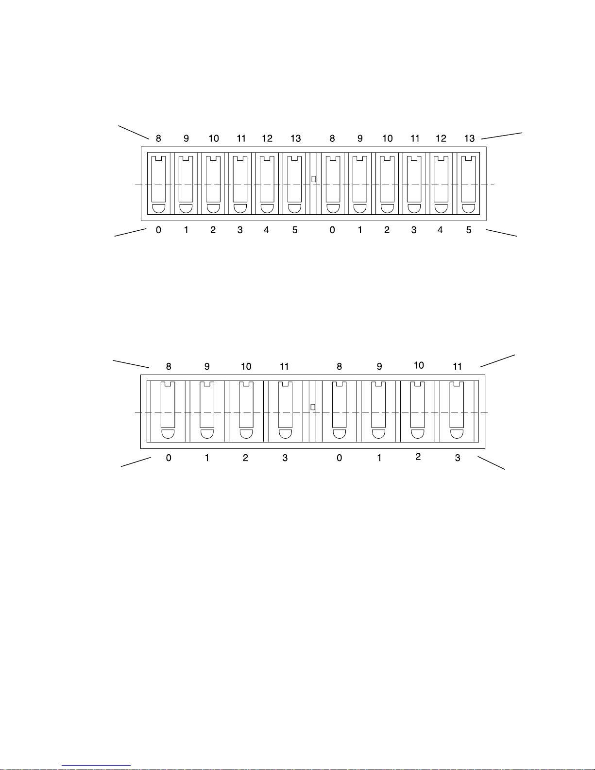
Option Switch
1. Disk Array 1 ID (FIGURE 2-7 for the 12-slot and FIGURE 2-8 for the 8-slot)
■ Up: 8–11 or 8–13 (factory default)
■ Down: 0–3 or 0–5
2. Disk Array 2 ID (
■ Up: 8–11 or 8–13
■ Down: 0–3 or 0–5 (factory default)
3. Drives Remote Start
■ Up: wait for SCSI command (factory default)
■ Down: check switch 4
4. Drives Delayed Start
FIGURE 2-7 for the 12-slot and FIGURE 2-8 for the 8-slot)
■ Up: start with (12 x SCSI device ID number) seconds delay (factory default)
■ Down: start at power-on
5. Reserved (No function)
16 Sun StorEdge A1000 and D1000 Installation, Operations, and Service Manual • November 2002
Page 41
Option Switch 2
Up
Default
SCSI Disk Array 2
SCSI Disk Array 1
Option Switch 1
Up
Default
Option Switch 2
Down
Option Switch 2
Up
Default
Option Switch 2
Down
Option Switch 1
Down
FIGURE 2-7 Sun StorEdge D1000 SCSI Disk ID Address Assignment —12-drive system
Option Switch 1
SCSI Disk Array 2
SCSI Disk Array 1
Up
Default
Option Switch 1
Down
FIGURE 2-8 Sun StorEdge D1000 SCSI Disk ID Address Assignment —8-drive system
Chapter 2 Product Overview 17
Page 42

LEDs on the Back
■ Power Supply Status, one two-color LED on each power module:
■ Lights green when the power supply is operating properly
■ Lights amber when the power supply has failed but the other power supply is
operating normally, or when the power cord is unplugged
■ Off if both power supplies are not plugged in or have failed
■ Cooling Status, 2 two-color LEDs on each cooling canister (one for each blower):
■ lights green when the individual blower is operating properly
■ lights amber when the individual blower has failed
■ Off when the cooling canister is not inserted
The D1000 controller interface board has 2 single-color LEDS.
■ The Temperature Fault LED
■ Lights amber when the board has detected a thermal fault
■ Off when the temperature is normal
■ The Controller Interface BoardPower LED
■ Lights green when the controller interface board is powered on
■ Off when the controller interface board is receiving no power
Power Modules
The Sun StorEdge D1000 system has two hot-pluggable and interchangeable power
supplies. Two DC power supplies in the chassis provide power to the internal
components, converting incoming AC voltage to DC voltages. These are redundant
power supplies—one power supply will maintain electrical power to the system if
the other power supply fails. Both power supplies are removable canisters that slide
into one of two slots on the back of the system. Each canister has a locking handle, a
power status LED, and an AC power cord connector.
Cooling System
The Sun StorEdge D1000 system has two cooling canisters. Each contains two
blowers. The cooling canisters are hot-pluggable and interchangeable.
The D1000 system can operate fully cooled with three of the four blowers
functioning. If two blowers fail, the remaining two can maintain the system in a 30C
environment, but the reliability of the components may be affected.
18 Sun StorEdge A1000 and D1000 Installation, Operations, and Service Manual • November 2002
Page 43

The blower speeds are variable and increase their speed to counteract unusual
cooling conditions, such as one failed blower or increased internal temperature.
Caution – Do not operate the system for extended periods with one or more
redundant modules not installed. The cooling system will become inefficient.
Disk Drives
See the documentation that comes with your system for information about the
drives installed in your system.
Sun StorEdge D1000
In a Sun StorEdge D1000, the Unix File System software identifies the drives as
follows:
■ 8-drive system (default switch setting)
(where t is the drive number)
cxt0dxsx, cxt1dxsx, cxt2dxsx, cxt3cxsx and
cxt8dxsx, cxt9dxsx, cxt10dxsx, cxt11dxsx
■ 12-drive system (default switch setting)
(where t is the drive number)
cxt0dxsx, cxt1dxsx, cxt2dxsx, cxt3cxsx, cxt4cxsx, cxt5cxsx and
cxt8dxsx, cxt9dxsx, cxt10dxsx, cxt11dxsx, cxt12cxsx,
cxt13cxsx
Dummy Drives
If you ordered a system with less than the maximum number of disk drives, dummy
drives fill the holes for the emply slots. The dummy drives are air baffles; they allow
the system to maintain maximum cooling. If any slot does not contain a disk drive,
you must fill the slot with a dummy drive so the unit will cool properly.
Chapter 2 Product Overview 19
Page 44

Sun StorEdge D1000 Software
Considerations
The Sun StorEdge D1000 may be used as simply additional disk storage for an
existing host system; it may be used in conjunction with Veritas™ VxVm in a RAID
based system. See the Veritas software user’s guide on your system CD. A Veritas
VxVm license can be obtained from Sun.
20 Sun StorEdge A1000 and D1000 Installation, Operations, and Service Manual • November 2002
Page 45

CHAPTER
3
Removing and Replacing
Components
The Sun StorEdge A1000 and D1000 systems contain easy access components, some
of which are hot-pluggable and some of which must be replaced with the power off.
Hot-pluggable Parts
■ Hard Disk Drives
■ Cooling Canisters
■ Power Supplies
Replaceable with Power Off
■ Sun StorEdge D1000 controller board
■ Sun StorEdge A1000 controller board
■ Sun StorEdge A1000 Battery
■ Sun StorEdge A1000 SIMMs
21
Page 46
Replacing Hot-Pluggable Parts
Hard Disk Drives
The Sun StorEdge A1000 or D1000 system you ordered comes configured with either
1.6-inch drives or one-inch drives. The procedure for removing and replacing the
drives differs only in the software you use to control the disks. In all cases the hard
disks are hot-pluggable.
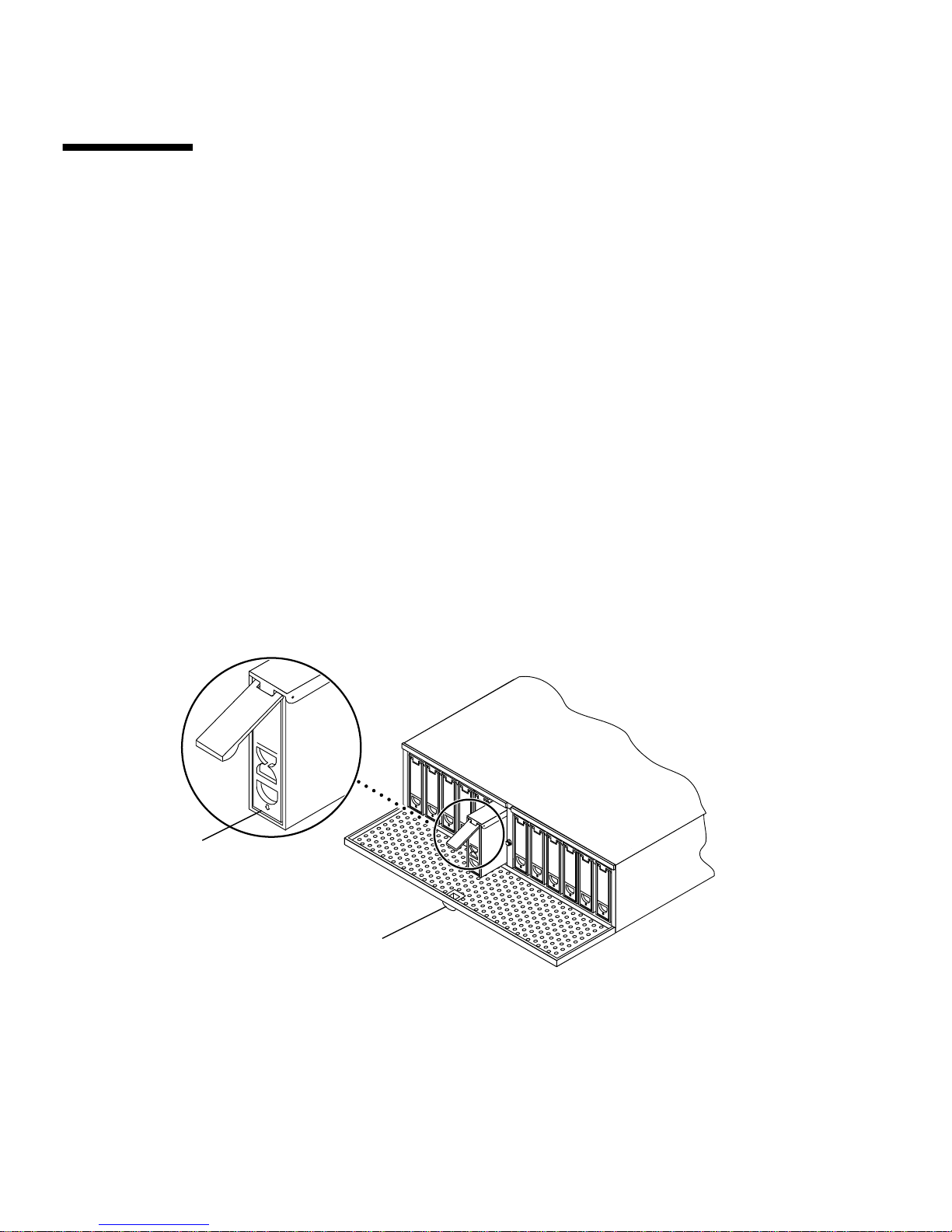
▼ To Remove a Disk Drive
1. Be sure there is no activity to the drives and prepare the software environment.
See the documentation that came with your software.
■ Instructions for hot plugging or unplugging a disk in the Sun StorEdge A1000
system are in RAID Manager documentation.
■ Instructions for hot plugging or unplugging a disk in the Sun StorEdge D1000
system are in Sun StorEdge D1000 Storage Guide.
Arrow
Button Latch
FIGURE 3-1 Removing and Replacing a Disk Drive
2. Unlock and open the door at the front of the chassis.
Push down the button latch at the center of the door (
22 Sun StorEdge A1000 and D1000 Installation, Operations, and Service Manual • November 2002
FIGURE 3-1).
Page 47
3. Unlatch the drive bracket handle to release it (FIGURE 3-1).
Push down in the direction of the arrow to release the latch.
4. Pull the bracket handle out and swing it open.
5. Continue to pivot the disk drive bracket handle against the chassis, applying mild
pressure until the drive disconnects.
6. Slide the drive out
▼ To Replace a Disk Drive
1. Hold the locking handle on the disk drive open (FIGURE 3-1).
2. Slide the replacement disk drive into the vacant slot.
3. Gently push the drive until the locking handle engages.
4. Close the locking handle handle completely, using gentle downward pressure.
Cooling Canisters
The Sun StorEdge A1000 or D1000 comes with two cooling canisters, each of which
contains two blowers. If any of the blowers fails, the LED on the back of the system
lights amber, indicating which blower has failed. To replace a blower, replace the
entire canister.
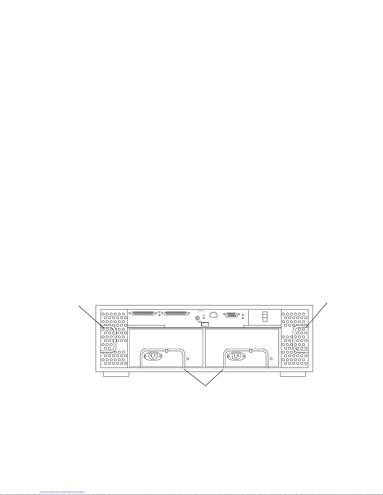
Cooling Canister Locking Handles
FIGURE 3-2 Rear of Sun StorEdge A1000 System
Cooling Canister Locking Handles
Power Supply Locking Handles
Chapter 3 Removing and Replacing Components 23
Page 48
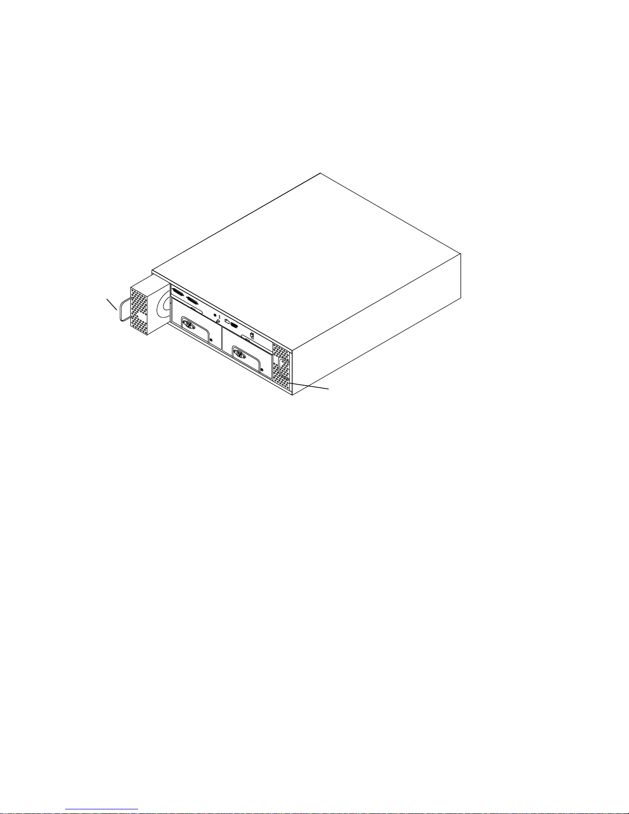
▼ To Remove and Replace a Cooling Canister
1. Release the locking handle and pull the cooling canister out (FIGURE 3-2 and
Locking Handle
FIGURE 3-3).
Locking Handle
FIGURE 3-3 Removing and Replacing a Cooling Canister
2. Orient the new cooling canister so that the round intake holes face inward and the
locking handle is on the outside edge of the canister on each side.
The locking handle should face inward when it is closed.
3. Slide the new cooling canister into the slot and push it until it engages.
The LEDs for the cooling canister light green when the connector is properly
engaged.
4. Close the locking handle.
Power Supplies
The Sun StorEdge A1000 or D1000 enclosure comes with two power supplies. The
LED on the power supply lights amber when the power supply fails. Although the
system can run well with only one power supply, the faulty one should be replaced
in case the good one goes bad. You can replace a failed or failing power supply
without turning the system off.
24 Sun StorEdge A1000 and D1000 Installation, Operations, and Service Manual • November 2002
Page 49
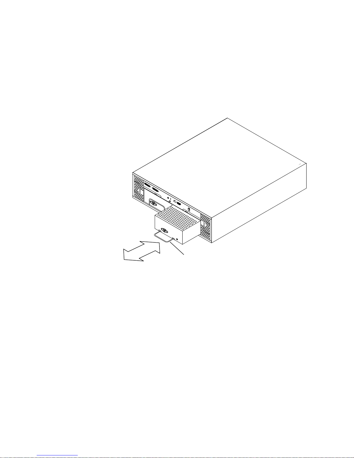
▼ To Replace a Power Supply
1. Disconnect the power cord from the power supply you intend to replace.
You cannot remove the power supply without first disconnecting the power cord.
See
FIGURE 3-2. and FIGURE 3-3 for the positions of the power connector and locking
handle.
Locking Handle
FIGURE 3-4 Removing and Replacing a Power Supply
2. Pull the locking handle down and slide the power supply out of the bay
(
FIGURE 3-4).
3. Slide the new power supply into the bay.
Small rails on the power supply base fit into cut-outs in the chassis.
4. Push firmly until the power supply connector engages.
5. With the locking handle in the closed (up) position, connect the power cord.
The LED for the power supply should light green.
Chapter 3 Removing and Replacing Components 25
Page 50
Replacing Parts with the Power Off
Controller Board
You must turn off the power to replace the controller board in either the Sun
StorEdge A1000 and D1000 versions of the system.
▼ To Remove the Controller Board
Caution – If the Sun StorEdge D1000 array is part of a Sun StorEdge A3500 array or
a Sun StorEdge A3500FC array, please refer to FIN I0670-1 for additional precautions
that must be taken to ensure the proper replacement of the controller/ESM card.
1. Stop the software communication with the Sun StorEdge A1000 or D1000 system.
See the documentation that came with your software.
2. Turn off the power to the system.
Push the power switch to the standby position. Press the left side of the switch.
3. Remove the SCSI cables and terminators on the controller board.
4. Attach an antistatic wrist strap to the exposed metal part of the chassis at the
center post between the power supply bays.
26 Sun StorEdge A1000 and D1000 Installation, Operations, and Service Manual • November 2002
Page 51
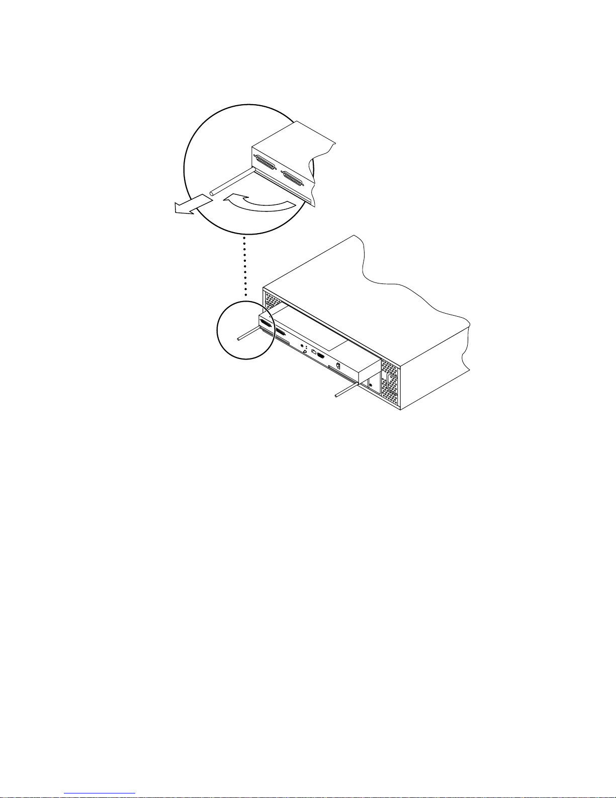
FIGURE 3-5 Controller Board Levers
5. Slide the controller board canister out and set it on an antistatic mat.
a. Use the levers at each side to release the controller board.
b. Hold the levers to slide the canister out.
Chapter 3 Removing and Replacing Components 27
Page 52
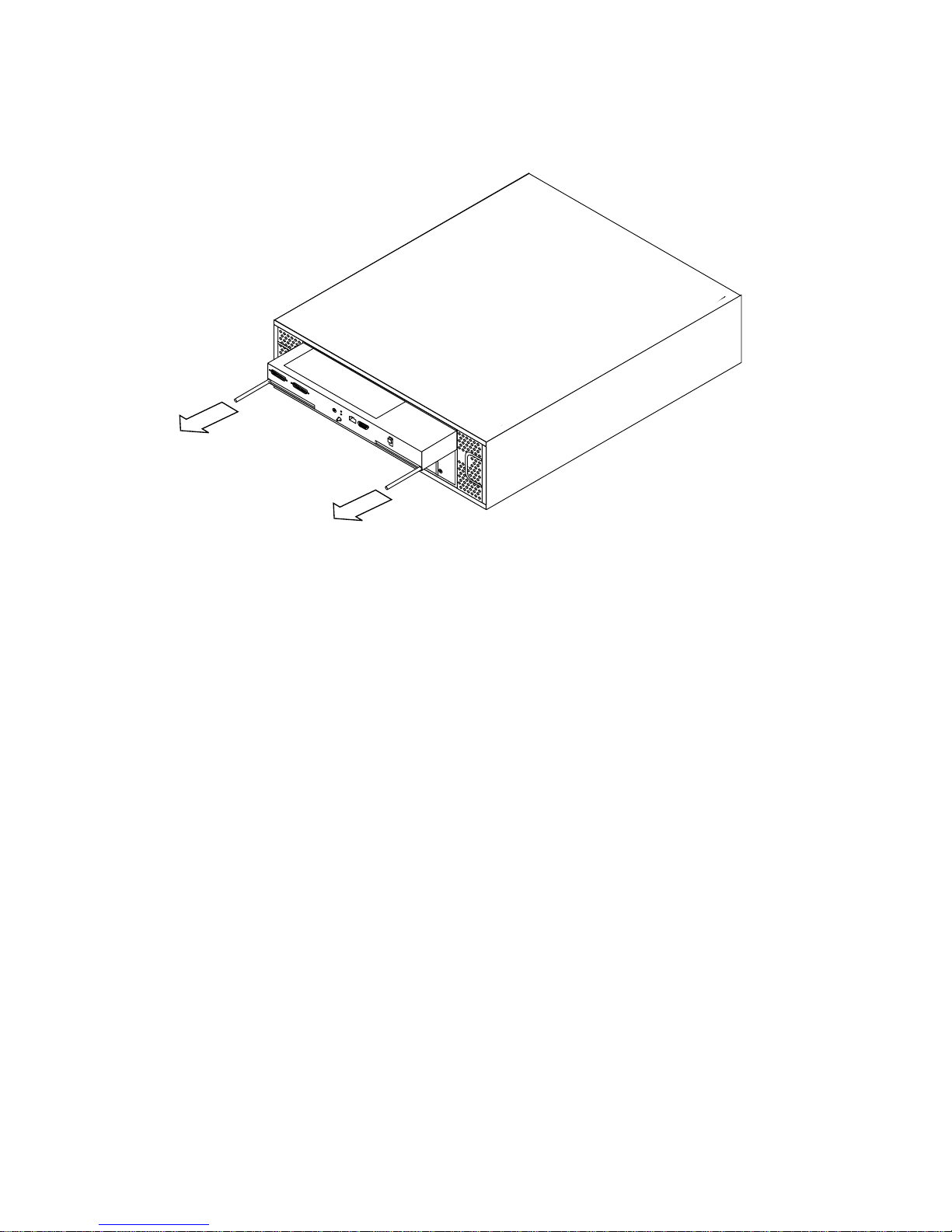
FIGURE 3-6 Removing the Controller Board
▼ To Replace the Controller Board
1. Slide the replacement controller board in its canister into the slot in the chassis.
The top of the canister has rails that fit into guide hooks in the chassis.
2. Push firmly until the controller board connector engages.
3. Push both handles inward until they are flush with the canister.
4. Connect the cables and remove the antistatic strap.
5. Turn the power on.
Push the power switch to the momentary on position (right side) and then release it.
Battery (A1000 Only)
You must turn off the power to replace the battery. Note all the cautions and
warnings in this chapter and the safety information at the front of the book.
▼ To Replace the Battery
Replace the battery only with the same type of Sun Microsystems battery.
28 Sun StorEdge A1000 and D1000 Installation, Operations, and Service Manual • November 2002
Page 53
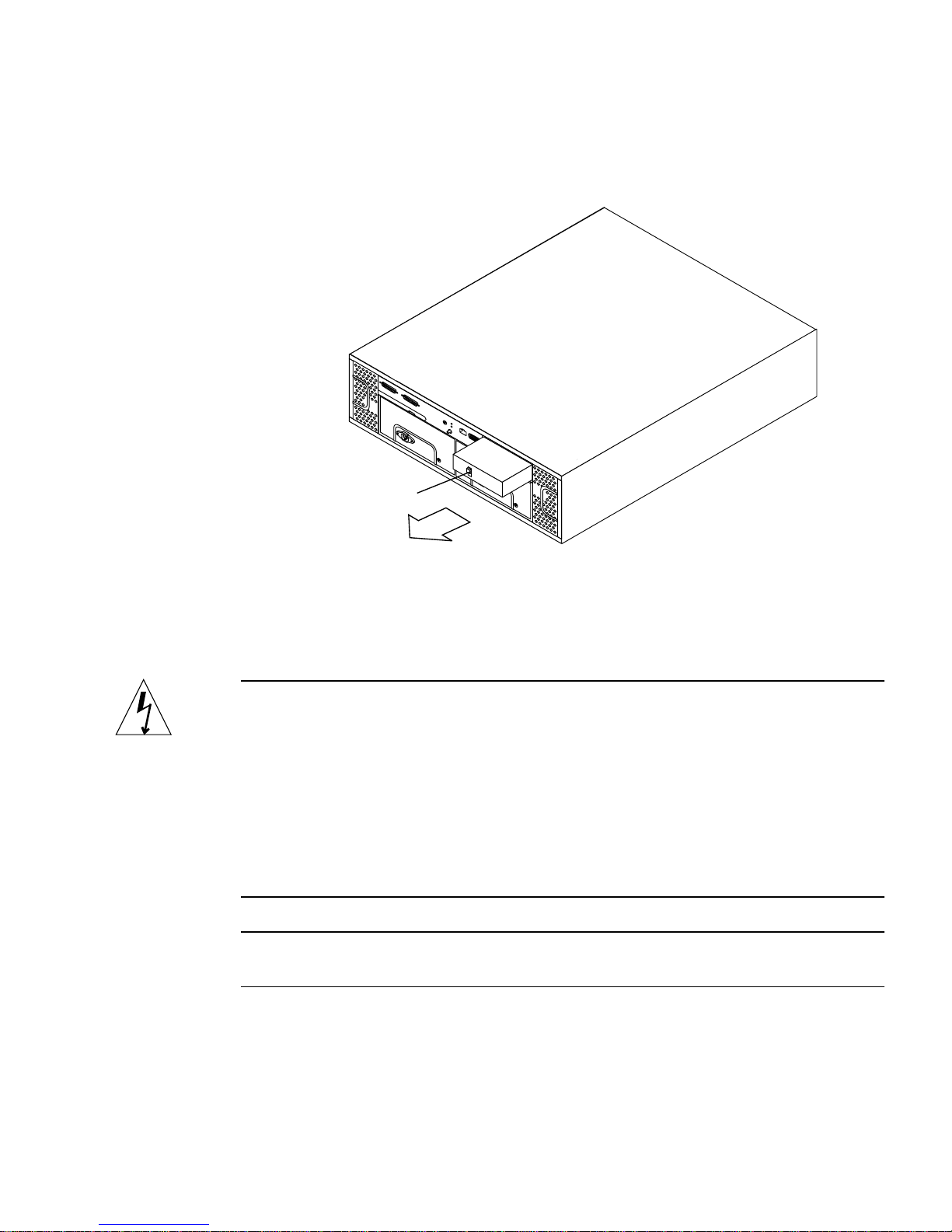
1. Locate the battery on the back of the unit. See FIGURE 3-2.
Battery Catch
FIGURE 3-7 Removing the Battery
2. Push down the catch on the outside of the battery.
3. Pull the battery out.
Caution – There is a sealed lead acid battery in Sun StorEdge A1000 units. There is
danger of explosion if the battery pack is mishandled or incorrectly replaced.
Replace only with the same type of Sun Microsystems battery pack.
Dispose of the battery properly in accordance with local regulations. Do not
mishandle it, disassemble it, or attempt to recharge it outside the system. Do not
dispose of the battery in fire.
If the used battery is physically damaged and is leaking electrolyte gel, do not
process it for recycling. Manage damaged batteries according to your local
regulations, which may include management as a hazardous waste.
Note – If the replacement battery arrives with return paperwork, you must fill out
this paperwork and return the battery as instructed.
4. After properly disposing of the spent battery, slide the new one into the battery
port in the controller board.
Be sure the battery is firmly seated.
Chapter 3 Removing and Replacing Components 29
Page 54
5. Set the battery age.
# raidutil -c cxtxd0s2 -R
SIMM Upgrade Procedure (A1000 only)
The following procedure provides instructions for upgrading the A1000 controller
board from the factory configured 24 Mbytes to an 80 Mbyte system.
Caution – Be sure to have an antistatic wrist strap and mat ready for the SIMMs
and the controller board.
1. Follow the procedure for removing the controller board from the system. See “To
Remove the Controller Board.”
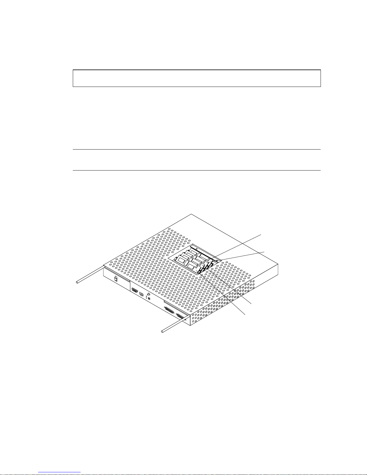
4 Mbyte
4 Mbyte
8 Mbyte
8 Mbyte
FIGURE 3-8 A1000 Controller—Fully populated with 8 Mbyte and 4 Mbyte SIMMs
(factory configuration)
2. Flip the controller canister over so you can see the SIMM cover.
See the orientation of the SCSI ports.
3. Remove the two screws that hold the SIMM cover to the center of the controller
canister and remove the cover.
This exposes the SIMMs (
30 Sun StorEdge A1000 and D1000 Installation, Operations, and Service Manual • November 2002
FIGURE 3-8).
Page 55
4. Attach the antistatic wrist strap to your wrist and an unpainted metal part of the
chassis.
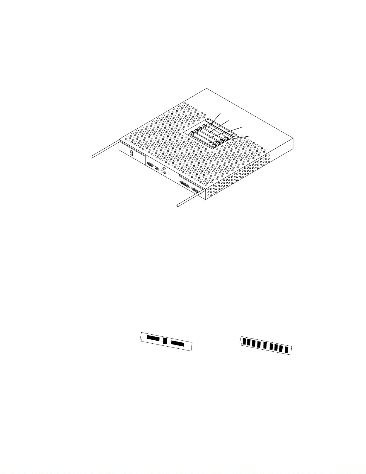
Slot A
Slot B
Slot C
Slot D
FIGURE 3-9 A1000 Controller—Empty SIMM slots
5. Remove the SIMMs and set them on an antistatic mat.
Remove the SIMMs from front to back. Press the small latch on each side of the
SIMM that releases it from the slot (
a. Remove first two SIMMs from slot D and slot C (
FIGURE 3-10).
FIGURE 3-10) and set them
aside.
These are 8 Mbyte SIMMs. You will use these SIMMs later.
b. Remove the SIMMs from slot B and slot A (
FIGURE 3-9).
These are the 4 Mbyte SIMMs which you can save for use in other hardware.
4 Mbyte SIMM (ICs on front side only)
8 Mbyte SIMM (ICs on both sides)
FIGURE 3-10 SIMMs
32 Mbyte SIMM (upgrade only)
6. Replace the 8 Mbyte SIMMs into slot A and slot B (FIGURE 3-9).
The SIMM is keyed and will fit only one way (notch in lower left corner)
(
FIGURE 3-10).
Chapter 3 Removing and Replacing Components 31
Page 56

7. Remove the two 32 Mbyte SIMMs from the antistatic packaging. Install them into
slot C and slot D (
FIGURE 3-9).
8. Place the part number label supplied with the upgrade kit over the barcode label
near the SIMM access door.
The new part number label correctly identifies your controller upgrade.
9. Remove the antistatic strap and replace the lid to the canister.
Secure the screws.
10. Replace the canister into the Sun StorEdge A1000 unit. See “To Replace the
Controller Board.”
FIGURE 3-11 Sun StorEdge A1000—SIMM Upgrade
32 Sun StorEdge A1000 and D1000 Installation, Operations, and Service Manual • November 2002
Page 57

APPENDIX
A
System Specifications
Physical Specifications
The outside measurements of the chassis are as follows:
■ Width: 53.34 cm (21.0 in)
■ Depth: 44.7 cm (17.6 in)
■ Height: 17.78 cm (7.0 in)
■ Weight: A1000 without disk drives: 19.3 kg (42.5 lbs)
fully loaded: 28.4 kg (62.5 lbs)
D1000 without disk drives: 18.6 kg (41.0 lbs)
fully loaded: 27.4 kg (60.5 lbs)
The unit’s total weight depends on the number of components installed in the
chassis.
Electrical Specifications
TABLE A-1 AC Power Requirements
Electrical Element Requirement
Voltage 100 VAC to 240 VAC
Frequency 47 - 63 Hz
Idle 2.14 amps
33
Page 58

TABLE A-1
AC Power Requirements
Electrical Element Requirement
Max. Operating 2.6 amps
Max. Surge 22 amp peaks
1
Typical current ratings at 240 volts AC, 60 Hz. Assumes a
0.70 power efficiency,0.99 power factor.
34 Sun StorEdge A1000 and D1000 Installation, Operations, and Service Manual • November 2002
Page 59

Environmental Specifications
Table A-2Environmental Requirements
Climate Control Location Minimum to Maximum Range
Temperature (dry bulb) Operating 5˚C to 40˚C
Storage -20˚C to 60˚C
Transit -20˚C to 60˚C
Temperature Derating (max.)
Relative Humidity (non-condensing) Operating 20% to 80%
Altitude (based on drives)
Heat Dissipation (maximum) Operating 260 Watts, 1092 BTU per hour
Sound Power and Pressure Operating 6.6 bels (power), 63.7 dBA (pressure)
* If you plan to operate the controller module at altitudes between 1000m and 3000m (3280 ft and 9850 ft), you must lower the environmental
temperature3.3˚ C (1.7˚ F) for every 1000m (3280 ft) above sea level.
*
Operating 3.3˚C per 1000m (1.7˚F per 1000 ft) above sea
level
Storage 10% to 93%
Transit 5% to 95%
Operating 3 Km (100 ft) below to 3,048m (10,000 ft) above
sea level
Storage 30.5m (100 ft) below to 3,048m (10,000 ft) above
sea level
Transit 30.5m (100 ft) below to 12,000m (40,000 ft) above
sea level
Appendix A System Specifications 35
Page 60

36 Sun StorEdge A1000 and D1000 Installation, Operations, and Service Manual • November 2002
 Loading...