

Page 1

SunSAI/P User’s Guide
Sun Microsystems, Inc.
901 San Antonio Road
Palo Alto, CA 94303-4900 USA
650 960-1300 Fax 650 969-9131
Part No. 805-6947-10
November 1998, Revision A
Send comments about this document to: [email protected]
Page 2

Copyright 1998Sun Microsystems, Inc., 901 San Antonio Road • Palo Alto, CA 94303 USA. All rights reserved.
This product or document is protectedby copyright and distributed underlicenses restrictingits use, copying, distribution, and
decompilation. No part ofthis productor document may be reproducedin any form byany means without prior writtenauthorization
of Sun and itslicensors, if any.Third-party software, including font technology, is copyrighted andlicensed fromSun suppliers.
Parts of the product may be derived from Berkeley BSD systems, licensed from theUniversity ofCalifornia. UNIXis aregistered trademark in
the U.S. and other countries, exclusively licensed through X/Open Company, Ltd.
Sun, Sun Microsystems,the Sun logo, AnswerBook, Java, the Java Coffee Cup, SunVTS, SunSolve, OpenBoot, and Solaris aretrademarks,
registeredtrademarks, or service marks of Sun Microsystems,Inc. inthe U.S.and othercountries. AllSPARCtrademarksare used under license
and are trademarks or registered trademarksof SPARCInternational, Inc.in theU.S. and othercountries. Products bearing SPARCtrademarks
arebased uponan architecturedevelopedby SunMicrosystems, Inc.
The OPEN LOOK and Sun™ Graphical User Interface was developedby SunMicrosystems, Inc. for its users and licensees. Sun acknowledges
the pioneering effortsof Xerox in researching and developing the concept of visual or graphical user interfaces for the computer industry. Sun
holds a non-exclusive license fromXerox to the Xerox GraphicalUser Interface,which licensealso coversSun’s licenseeswho implementOPEN
LOOK GUIs and otherwise comply with Sun’s written license agreements.
RESTRICTEDRIGHTS: Use, duplication, or disclosure bythe U.S. Government is subject to restrictions of FAR52.227-14(g)(2)(6/87) and
FAR52.227-19(6/87),or DFAR 252.227-7015(b)(6/95) and DFAR227.7202-3(a).
DOCUMENTATION ISPROVIDED “AS IS” AND ALL EXPRESS OR IMPLIED CONDITIONS, REPRESENTATIONSAND WARRANTIES,
INCLUDING ANY IMPLIED WARRANTY OF MERCHANTABILITY, FITNESS FOR A PARTICULAR PURPOSE OR NONINFRINGEMENT, ARE DISCLAIMED, EXCEPT TO THE EXTENT THAT SUCH DISCLAIMERS ARE HELD TO BE LEGALLY INVALID.
Copyright 1998 Sun Microsystems, Inc., 901 San Antonio Road • Palo Alto, CA 94303 Etats-Unis. Tousdroitsréservés.
Ce produit ou document est protégépar un copyright et distribué avec des licencesqui en restreignentl’utilisation, la copie, la distribution, et la
décompilation. Aucune partie de ce produit ou document ne peut être reproduitesous aucune forme, par quelque moyen que ce soit, sans
l’autorisation préalable et écrite de Sun et de ses bailleurs delicence, s’ily ena. Lelogiciel détenupar destiers, etqui comprendla technologie
relativeaux policesde caractères, est protégé parun copyrightet licenciépar desfournisseurs deSun.
Des parties de ce produitpourront être dérivéesdes systèmes BerkeleyBSD licenciéspar l’Université de Californie. UNIX est une marque
déposée auxEtats-Unis etdans d’autrespays et licenciée exclusivement par X/Open Company, Ltd.
Sun, Sun Microsystems,le logo Sun, AnswerBook, Java, le logo Jave Coffee Cup, SunVTS, SunSolve, OpenBoot, et Solaris sont des marques de
fabrique ou des marques déposées, ou marques de service, de Sun Microsystems,Inc. auxEtats-Unis etdans d’autrespays. Toutesles marques
SPARC sont utilisées sous licence et sont des marquesde fabrique ou des marques déposéesde SPARCInternational, Inc.aux Etats-Uniset
dans d’autres pays.Les produits portant les marquesSPARCsont basés sur une architecturedéveloppée par Sun Microsystems, Inc.
L’interfaced’utilisationgraphique OPEN LOOK et Sun™ a été développée par Sun Microsystems, Inc. pour ses utilisateurs et licenciés. Sun
reconnaîtles efforts de pionniers de Xerox pourla rechercheet le développement du concept des interfaces d’utilisation visuelle ou graphique
pour l’industrie de l’informatique. Sun détient une licence non exclusive deXerox sur l’interface d’utilisation graphique Xerox, cette licence
couvrant également les licenciésde Sunqui mettenten placel’interface d’utilisationgraphique OPENLOOK etqui en outre se conforment aux
licences écrites de Sun.
CETTE PUBLICATION EST FOURNIE "EN L’ETAT" ET AUCUNE GARANTIE, EXPRESSE OU IMPLICITE, N’EST ACCORDEE, Y
COMPRIS DES GARANTIES CONCERNANT LA VALEUR MARCHANDE, L’APTITUDE DE LA PUBLICATION A REPONDRE A UNE
UTILISATION PARTICULIERE, OU LE FAIT QU’ELLE NE SOIT PAS CONTREFAISANTE DE PRODUIT DE TIERS. CE DENI DE
GARANTIE NE S’APPLIQUERAIT PAS, DANS LA MESURE OU IL SERAIT TENU JURIDIQUEMENT NUL ET NON AVENU.
Please
Recycle
Page 3

Regulatory Compliance Statements
Your Sun product is marked to indicate its compliance class:
• Federal Communications Commission (FCC) — USA
• Department of Communications (DOC) — Canada
• Voluntary Control Council for Interference (VCCI) — Japan
Please read the appropriate section that corresponds to the marking on your Sun product before attempting to install the product.
FCC Class B Notice
This device complies with Part 15 of the FCC Rules. Operation is subject to the following two conditions:
1. This device may not cause harmful interference.
2. This device must accept any interference received, including interference that may cause undesired operation.
Note: This equipment has been tested and found to comply with the limits for a Class Bdigital device, pursuant to Part 15 of the FCC
Rules. These limits are designed to provide reasonable protection against harmful interference in a residential installation. This
equipment generates, uses and canradiate radio frequency energy and, if not installed and used in accordance with the instructions,
may cause harmful interference to radio communications. However, there is no guarantee that interference will not occur in a
particular installation. If this equipment does cause harmful interference to radio or television reception, which can be determined by
turning the equipment off and on, the user is encouraged to try to correct the interference by one or more of the following measures:
• Reorient or relocate the receiving antenna.
• Increase the separation between the equipment and receiver.
• Connect the equipment into an outlet on a circuit different from that to which the receiver is connected.
• Consult the dealer or an experienced radio/television technician for help.
Shielded Cables: Connections between the workstation and peripherals must be made using shielded cables in order to maintain
compliance with FCC radio frequency emission limits. Networking connections can be made using unshielded twisted pair (UTP)
cables.
Modifications: Any modifications made to this device that are not approved by Sun Microsystems, Inc. may void the authority
granted to the user by the FCC to operate this equipment.
DOC Class B Notice - AvisDOC, Classe B
This Class B digital apparatus meets all requirements of the Canadian Interference-Causing Equipment Regulations.
Cet appareil numérique de la classe B respecte toutes les exigences du Règlement sur le matériel brouilleur du Canada.
iii
Page 4
iv SunSAI/P User’s Guide • November 1998
Page 5

Declaration of Conformity
Compliance ID: DIGI-70000414
Product Name: SunSAI/P Adapter
This product has been tested and complies with Part 15 of the FCC Rules.
Operation is subject to the following two conditions:
1. This equipment may not cause harmful interference.
2. This equipment must accept any interference that may cause undesired operation.
EMC
This equipment complies with the following requirements of the EMC Directive 89/336/EEC:
EN55022 / CISPR22 (1985) Class B
EN50082-1 IEC801-2 (1991) 4 kV (Direct), 8 kV (Air)
IEC801-3 (1984) 3 V/m
IEC801-4 (1988) 1.0 kV Power Lines, 0.5 kV Signal Lines
EN61000-3-2/IEC1000-3-2(1994) Pass (Class D)
Supplementary Information
This product was tested and complies with all the requirements for the CE Mark when connected to a Sun workstation or server.
/ S / / S /
Dennis P. Symanski DATE John Shades DATE
Manager, Product Compliance Quality Assurance Manager
Sun Microsystems, Inc. Sun Microsystems Scotland, Limited
901 San Antonio Road, M/S UMPK15-102 Springfield, Linlithgow
Palo Alto, CA 94303, USA West Lothian, EH49 7LR
Tel: 650-786-3255 Scotland, United Kingdom
Fax: 650-786-3723 Tel: 0506 670000
Fax: 0506 760011
v
Page 6

vi SunSAI/P User’s Guide • November 1998
Page 7

Contents
1. Introduction 1
Components 1
Features 1
Board Operation 2
Customer Assistance 2
2. Installing SunSAI/P Boards 3
Before You Install the Board 3
▼ Installing the Board 3
Memory Window Size and Starting Address 4
3. EIA-232 Connectors and Cables 5
Connectors 5
Cables 6
Grounding 6
Environment 7
Capacitance vs. Length of Run 7
4. Connecting Peripherals 9
Connecting to a Modem 9
Connecting to a DTE Device 10
vii
Page 8

Software Handshaking (XON/XOFF) 10
Hardware Handshaking (Ready/Busy) 12
5. Device Driver Installation 13
Removing Previous Versions of the Driver Software 13
Installing the Driver Software Using pkgadd 14
Directory Structure 16
Loading the Driver 18
Using saipconfig to Configure the Driver Software 18
Rebooting the System 19
Automatic Configuration 19
Manual Configuration 20
Creating New Devices 23
Enabling the New Ports 24
Viewing the Man Pages 25
Editing the C Shell Environment 25
Editing the Bourne or Korn Shell Environments 26
Viewing the Man Pages 26
Un-Installing the Device Driver 27
6. TTY Devices 29
7. Setting Terminal Options with the sitty Utility 31
8. Sun Port Manager 35
Using SPM 35
A. Error Messages 37
B. Specifications 39
Power Requirements 39
viii SunSAI/P User’s Guide • November 1998
Page 9

Board Dimensions 39
Operating Environment 39
Serial Interface Surge Suppression 39
C. SunVTS Diagnostic Testing 41
Index 43
Contents ix
Page 10

x SunSAI/P User’s Guide • November 1998
Page 11

Figures
FIGURE 3-1 Eight-Port Connector Box 6
FIGURE 4-1 Modem Cable 9
FIGURE 4-2 Simple Terminal/Printer Cable 11
FIGURE 4-3 Terminal/Printer Cable with DTR Handshaking 12
FIGURE 5-1 SunSAI/P Software Directory Structure (/etc and /kernel Directories) 16
FIGURE 5-2 SunSAI/P Software Directory Structure (/opt Directory) 17
xi
Page 12

xii SunSAI/P User’s Guide • November 1998
Page 13

Tables
TABLE 3-1 DB-25 Connector Pin Assignments 5
TABLE 5-1 Format Used For Port Names 23
TABLE 7-1 sitty Options 32
TABLE C-1 SunVTS Documentation 41
xiii
Page 14

xiv SunSAI/P User’s Guide • November 1998
Page 15

CHAPTER
1
Introduction
The SunSAI/P User’s Guide covers the installation and configuration of the SunSAI/P
intelligent serial communications boards in Sun™ Microsystems™ PCI workstations
running the Solaris™ 2.5.1 Hardware: 4/97, 8/97, 11/97, Solaris 2.6, and Solaris 7
operating environments.
In addition to the adapter itself, you will also need to install device driver software
for your operating system, so that programs can communicate with the board.
Device driver installation instructions are included in this manual, after the
hardware installation instructions.
Components
The carton in which your SunSAI/P board was shipped should contain the
following items:
■ SunSAI/P board
■ SunSAI/P User’s Guide (this book)
■ One or more software packets containing device driver CD-ROM
■ Connector assembly
Features
■ Serial asynchronous board with eight ports
■ Maximum speed 115K bps per port
■ Meets PCI local bus specification rev. 2.1
■ PCI card: 32 bit data width, short length with 33 MHz operating frequency and
5.0 or 3.3 volts I/O signalling (universal card)
1
Page 16

Board Operation
The SunSAI/P board is a multi channel intelligent Serial Asynchronous Interface
board for computers incorporating the PCI bus standard.
The heart of the SunSAI/P board is a 32-bit RISC processor. The board has 128 KB of
dual-ported high-speed RAM used for program code and data buffering. The
SunSAI/P board supports “preset” throughput speeds of up to 115K bps for each
asynchronous port.
The processor and dual ported RAM relieves your computer of the burden of
managing the serial ports. The computer can transfer large blocks of data directly to
the memory on the board, then move on to other tasks while the board sends the
data out the serial ports one character at a time. Similarly, the board receives input
data and stores it in buffers in its dual ported RAM, so the computer only needs to
check periodically to see if data is available.
The dual ported RAM is memory which is accessible for read and write operations
by both the board and the computer. To the computer, the dual ported RAM looks
exactly like its own memory, and can be accessed by the same high speed memory
referencing commands it uses for its internal memory. This means that a block of
data that may take a number of seconds for the SunSAI/P board to receive or
transmit to the outside world can be transferred between the board and the
computer in mere microseconds.
The SunSAI/P board’s dual ported RAM is mapped into a 4 Megabyte unused area
in the host computer’s memory address space.
Customer Assistance
Be sure to read the Release Notes that may be included with this software. The
Release Notes contain information not available at this manual’s press time.
For assistance in the United States, please call 1-800-USA-4SUN.
For information on how to get the latest patches and patch revision, please visit the
SunSolve
Service provider. For additional information, access Sun on the World Wide Web at
http://www.sun.com and select Sales and Service.
2 SunSAI/P User’s Guide • November 1998
sm
website at http://sunsolve.sun.com, or contact your local Sun
Page 17

CHAPTER
2
Installing SunSAI/P Boards
Before You Install the Board
Write down the serial number of the board. You will need it if you have to contact
Sun regarding the board.
There are no switches or jumpers on the SunSAI/P board.
SunSAI/P boards contain static-sensitive components. Always touch a grounded
surface to discharge static electricity before handling the circuit board.
▼ Installing the Board
Now you are ready to install the SunSAI/P board in your computer. Follow these
steps:
Note – Refer to your system installation or service manual for detailed instructions
for the following steps.
1. Power off your system, using the standard shut down procedures described in the
Solaris Handbook for Sun Peripherals or your system service manual.
The Solaris Handbook for Sun Peripherals is shipped with the Solaris operating
environment software and is available on the http://docs.sun.com website.
2. Locate an available PCI slot in your computer and remove the slot plate.
3. Install the SunSAI/P board according to the instructions in the platform service or
installation manual.
3
Page 18

4. Install the connector box assembly on the SunSAI/P board by connecting the male
78-pin plug on the assembly to the female 78-pin connector on the end of the
SunSAI/P board. Be sure that the plug is completely installed—it may be a snug
fit.
Note – If you have difficulty connecting the DB-78 connector, try loosening the
screw in the endplate (the connector may not be exactly centered in the slot in the
back of the computer). Be sure to re-tighten the endplate screw once the DB-78
connector is securely attached.
5. Screw the connector into the board's endplate. Do not over-tighten the screws. If
the screws don't go in several turns, or if they don't reach the nuts in the endplate,
the 78-pin connectors are probably not completely mated.
6. Replace your computer's cover.
7. Power on your system, using the procedures described in the Solaris Handbook for
Sun Peripherals or your system service manual.
Memory Window Size and Starting
Address
The memory starting address is determined by the system. No switches or jumpers
are required to change these parameters.
The SunSAI/P board requires 4 Mbytes of unused PCI memory address space in
your computer.
4 SunSAI/P User’s Guide • November 1998
Page 19

CHAPTER
3
EIA-232 Connectors and Cables
Connectors
SunSAI/P boards are shipped with a connector box which provides eight female
DB-25 EIA-232 connectors wired for data terminal equipment (DTE) operation.
TABLE 3-1 DB-25 Connector Pin Assignments
Signal Description DTE Use Pin #
GND Chassis Ground N/A Shell
TxD Transmitted Data Output 2
RxD Received Data Input 3
RTS Request To Send Output 4
CTS Clear To Send Input 5
DSR Data Set Ready Input 6
SG Signal Ground reference 7
DCD Data Carrier Detect Input 8
DTR Data Terminal Ready Output 20
RI Ring Indicator Input 22
The pin assignments for the DB-25 connectors follow the usual conventions for
EIA-232 wiring.
5
Page 20
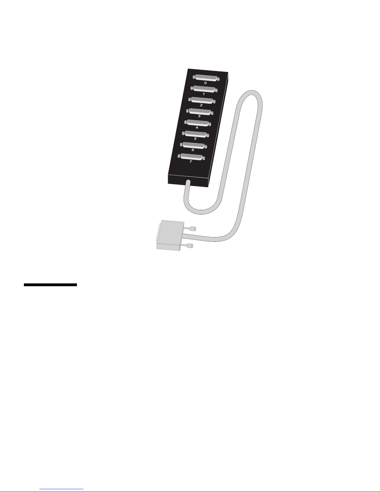
FIGURE 3-1 Eight-Port Connector Box
Cables
EIA-232 serial interface cables should be shielded, low capacitance cables, ideally
designed specifically for serial data transmission.
Grounding
The shield should be grounded at both ends of the cable. Chassis Ground, available
on the shell of the DB-25 connectors, is ideal for this purpose.
6 SunSAI/P User’s Guide • November 1998
Page 21

Environment
While good shielding provides reasonable protection against “noise” (ElectroMagnetic Interference, or EMI), cables should still be routed away from noise
sources wherever possible. Avoid laying cables in close proximity to transformers,
generators, motors, fluorescent lights, etc.
Capacitance vs. Length of Run
The total capacitance of a cable affects the integrity of transmitted data. As a rule of
thumb, the total capacitance of a cable (including the connectors) should not exceed
2500 pF for baud rates of up to 57,600 (1200pF for 115K baud and 600 pF for 230K
baud). Serial interface cable is usually rated in pico Farads per foot. Therefore, if a
cable has a capacitance of 50 pF/ft, and the connectors are 100 pF each, the
maximum recommended cable length is 46 feet for baud rates of up to 57,600. If the
cable is rated at 12.5 pF/ft, the maximum recommended cable length is 184 feet, and
5 pF/ft cable can be run up to 460 feet.
In situations where low-capacitance cable is unavailable, or very long cable runs are
required, “short-haul” modems, available from suppliers such as Black Box, can be
used to increase the effective range of the EIA-232 interface. Short-haul modems are
similar to standard modems, except that they are connected directly to each other
via a cable instead of going through a telephone circuit.
Note – Use only externally-powered short-haul modems with the SunSAI/P
adapter.
Chapter 3 EIA-232 Connectors and Cables 7
Page 22

8 SunSAI/P User’s Guide • November 1998
Page 23
CHAPTER
4
Connecting Peripherals
This section discusses various methods of connecting peripheral devices to the
SunSAI/P adapter.
Sample cable diagrams are provided to aid in constructing the correct cable for your
application.
Note – The cables shown in this section are for information only and are not
supplied by Sun Microsystems.
Connecting to a Modem
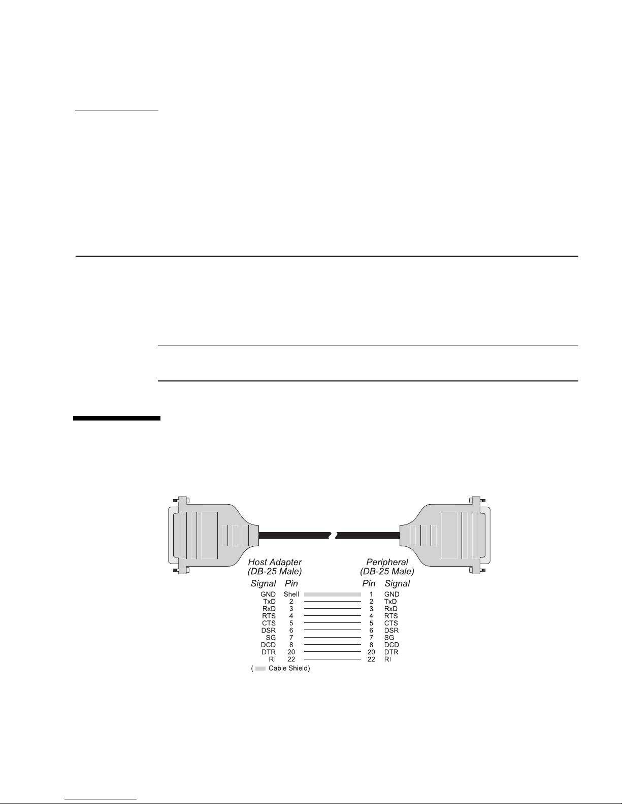
FIGURE 4-1 Modem Cable
9
Page 24

To connect the SunSAI/P board to a modem, use a standard “straight-through” cable
(
FIGURE 4-1) to connect the modem to one of the DB-25 connectors on the connector
box.
Note – Shielded cable must be used to remain in compliance with Part 15 of FCC
rules.
Connecting to a DTE Device
A DTE device is a terminal, serial printer, another computer's serial port, etc. To
connect the SunSAI/P board (which is also a DTE device) to another DTE device,
you need a null modem cable or adapter.
Software Handshaking (XON/XOFF)
In most cases, serial terminals and printers need only a “three-wire” connection to
the SunSAI/P board. The Solaris device driver supports XON/XOFF (software)
handshaking, so the only signal lines necessary are Transmitted Data (TxD),
Received Data (RxD) and Signal Ground (SG). Cables must be shielded to remain in
compliance with FCC certification requirements, and the shield should be connected
to Chassis Ground (GND) at both ends of the cable run.
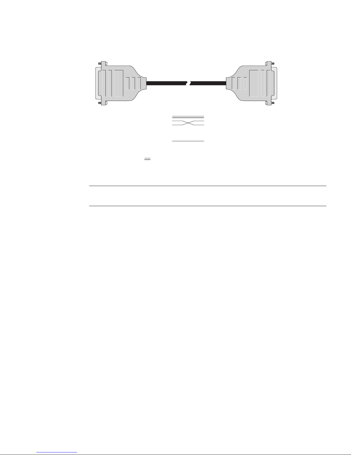
A simple cable for connecting a terminal or a printer to a DB-25 equipped SunSAI/P
board is shown below.
10 SunSAI/P User’s Guide • November 1998
Page 25
Host Adapter
(DB-25 Male)
Signal
( Cable Shield)
Pin Pin
Shell
GND
2
TxD
3
RxD
4
RTS
5
CTS
6
DSR
7
SG
8
DCD
20
DTR
22
RI
Peripheral
(DB-25 Male)
Signal
GND
1
TxD
2
RxD
3
RTS
4
CTS
5
DSR
6
SG
7
DCD
8
DTR
20
RI
22
FIGURE 4-2 Simple Terminal/Printer Cable
Note – Shielded cable must be used to remain in compliance with Part 15 of FCC
rules.
The cable shown in
FIGURE 4-2 is a three-wire null modem cable—that is, Transmitted
Data on one end of the cable is connected to Received Data at the other end, and vice
versa.
The male DB-25 end can be plugged directly into most serial terminals and printers
without any adapters. The female DB-25 end plugs directly into one of the DB-25
connectors on the connector box assembly.
Chapter 4 Connecting Peripherals 11
Page 26
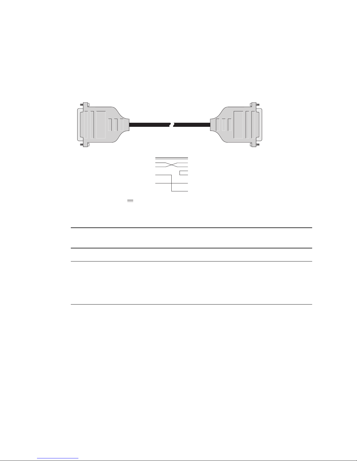
Hardware Handshaking (Ready/Busy)
Most terminals and printers use Data Terminal Ready (DTR) for Ready/Busy
hardware handshaking. The cable shown below supports this method.
Host Adapter
(DB-25 Male)
Signal
( Cable Shield)
Pin Pin
Shell
GND
2
TxD
3
RxD
4
RTS
5
CTS
6
DSR
7
SG
8
DCD
20
DTR
22
RI
Peripheral
(DB-25 Male)
Signal
GND
1
TxD
2
RxD
3
RTS
4
CTS
5
DSR
6
SG
7
DCD
8
DTR
20
RI
22
FIGURE 4-3 Terminal/Printer Cable with DTR Handshaking
Note – Shielded cable must be used to remain in compliance with Part 15 of FCC
rules.
Note – Some Okidata printers use a control signal on pin 11, called Supervisory
Send Data (SSD) instead of DTR. In this case, simply connect CTS on the female DB25 side to pin 11 of the male DB-25, instead of pin 20. Other printer manufacturers
may use different methods of flow control. Consult your printer's documentation for
specific wiring requirements.
12 SunSAI/P User’s Guide • November 1998
Page 27

CHAPTER
5
Device Driver Installation
Note – Software changes more rapidly than printed documentation can keep up.
For this reason, some of the screens or prompts may not appear exactly as shown.
Removing Previous Versions of the
Driver Software
Before installing the SunSAI/P driver software, you must first remove any previous
version of the SunSAI/P software that may be present on your system. If you
attempt to add the software packages over existing SunSAI/P packages, the
installation will fail.
1. Become superuser (root).
2. Check for any SunSAI/P software packages by using the pkginfo command:
# /usr/bin/pkginfo | grep SUNWsaip
If you find any SunSAI/P packages, you must remove them.
3. Remove any existing SunSAI/P software packages by using the pkgrm command:
# /usr/sbin/pkgrm SUNWsaip SUNWsaipu
13
Page 28

Installing the Driver Software Using
pkgadd
1. Log onto your system console as superuser (root).
2. Insert the SunSAI/P CD into your system’s CD-ROM drive.
The Solaris volume management software will mount the CD to the
/cdrom/sunsaip_2_0 directory.
3. To start the software installation, type:
# pkgadd -d /cdrom/sunsaip_2_0/Product SUNWsaip SUNWsaipu
Note – For more information about the pkgadd utility, refer to the pkgadd(1m)
man page or the Solaris documentation.
You will see the following, or similar, output:
Processing package instance <SUNWsaip> from </cdrom/sunsaip_2_0/Product>
Serial Asynchronous Interface Driver (PCI)
(sparc) 2.0,REV=year.month.day
Copyright 1998 Sun Microsystems, Inc. All rights reserved.
Automatically installing the default configuration.
To reconfigure or add new adapters, use the saipconfig utility.
The following has been automatically configured for adapter 1:
Adapter Type: 8-port PCI Async Intelligent Adapter.
Module Port Names
---------------------------
1 term/a000 - term/a007 -- also /dev/cua/axxx
Using </> as the package base directory.
## Processing package information.
## Processing system information.
6 package pathnames are already properly installed.
## Verifying disk space requirements.
## Checking for conflicts with packages already installed.
## Checking for setuid/setgid programs.
14 SunSAI/P User’s Guide • November 1998
Page 29

4. Answer yes (y) when asked to allow scripts to be run as superuser on your system.
This package contains scripts which will be executed with super-user
permission during the process of installing this package.
Do you want to continue with the installation of <SUNWsaip> [y,n,?] y
After several status messages, you will see the following, or similar, output:
Installation of <SUNWsaip> was successful.
Processing package instance <SUNWsaipu> from </cdrom/sunsaip_2_0/Product>
Serial Asynchronous Interface Utilities (PCI)
(sparc) 2.0,REV=year.month.day
Copyright 1998 Sun Microsystems, Inc. All rights reserved.
Using </opt> as the package base directory.
5. Answer yes (y) when asked to allow scripts to be run as superuser on your system.
This package contains scripts which will be executed with super-user
permission during the process of installing this package.
Do you want to continue with the installation of <SUNWsaipu> [y,n,?] y
The driver installation will continue automatically. When you will see the following
message, the driver software will have been successfully installed on your system.
Installation of <SUNWsaipu> was successful.
6. Unmount and eject the SunSAI/P CD.
Chapter 5 Device Driver Installation 15
Page 30
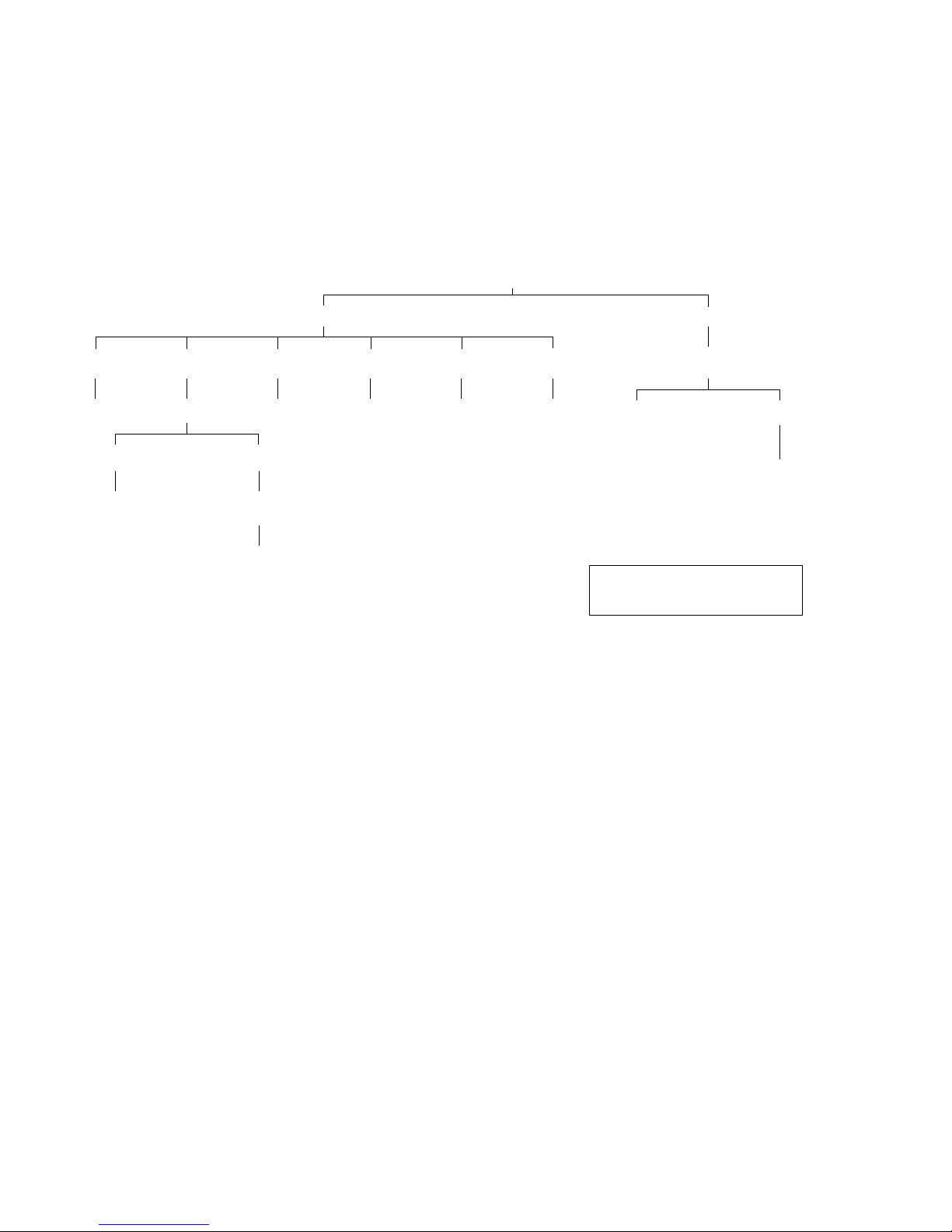
Directory Structure
FIGURE 5-1 and FIGURE 5-2 shows the directory structure of the SunSAI/P software
after it has been installed on your system.
root
/etc /kernel
/init.d
saip
saipconfig*
saipd*
/SUNWconn
/bin
/opt
FIGURE 5-1 SunSAI/P Software Directory Structure (/etc and /kernel Directories)
/rc0.d
K90saip
/saip
/bin
saipconfig
saipd
saipd32
saipd64
/rc1.d
K90saip
/rc2.d
S29saip
/rcS.d /drv
K90saip
saip
saip.conf
saipdl
saipdl.conf
* Signifies a symbolic link
/sparcv9
saip
saipdl
16 SunSAI/P User’s Guide • November 1998
Page 31
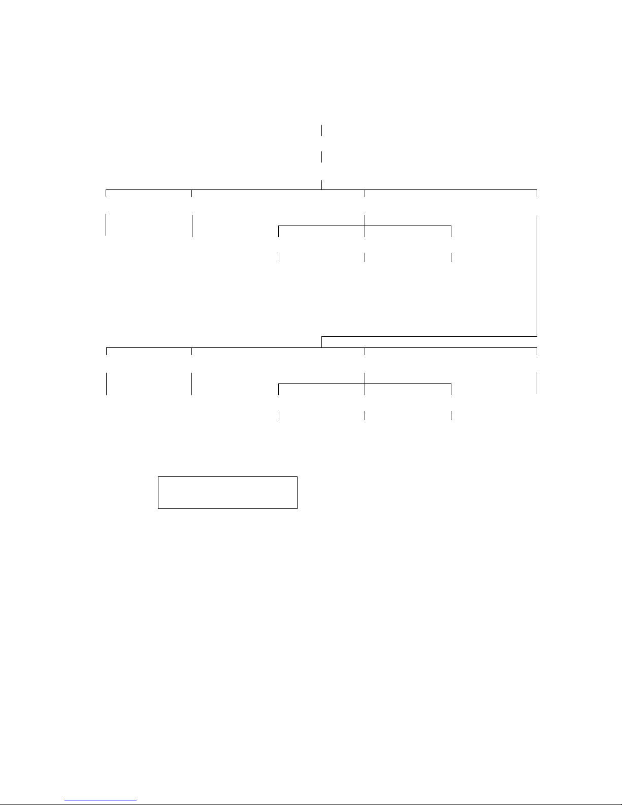
root
/opt
/SUNWconn
sitty*
spm*
sitty
sitty32
sitty64
spm
spm32
spm64
/include
saip.h*
/man1
sitty.1*
saip.h
/man1
sitty.1
* Signifies a symbolic link
/man
/man1m /man7d
saipd.1m*
spm.1m*
/man/bin /include
/man1m /man7d
saipd.1m
spm.1m
saip.7d*saipconfig.1m*
saipdl.7d*
saip.7dsaipconfig.1m
saipdl.7d
/saip/bin
/info
spm_info
spm_info1
spm_info2
spm_info3
spm_info4
spm_info5
spm_info6
FIGURE 5-2 SunSAI/P Software Directory Structure (/opt Directory)
Chapter 5 Device Driver Installation 17
Page 32

Loading the Driver
When the driver loads, you will see the following (or similar) message:
SUNWsaip port:0x00000000 mem=0x00400000 ports=8 SunSAI/P V x.x.x
If there is a problem with the board or the driver configuration, you may see error
messages after this screen—see Appendix A for explanations of the error messages
that may occur.
sitty options set from a run control (rc) script must be set after the download
program has run, and must wait for the board to boot before running.
sitty options should be added to the end of /etc/rc2.d. This can be done by
giving it a name such as “S99saip”or“S99sittystuff”, where the “S” must be a
capital letter, and the greater the number, the later the script is run.
Using saipconfig to Configure the
Driver Software
In some circumstances, you may want to configure the SunSAI/P device driver
manually. For example, you may want to use more adapters than are currently
loaded in the system, or you may need to change the default configuration. After
you have installed the driver software, use the saipconfig utility to configure the
driver software.
18 SunSAI/P User’s Guide • November 1998
Page 33
Rebooting the System
If you have installed additional boards since you have installed the driver software,
perform a reconfiguration boot before using the saipconfig utility.
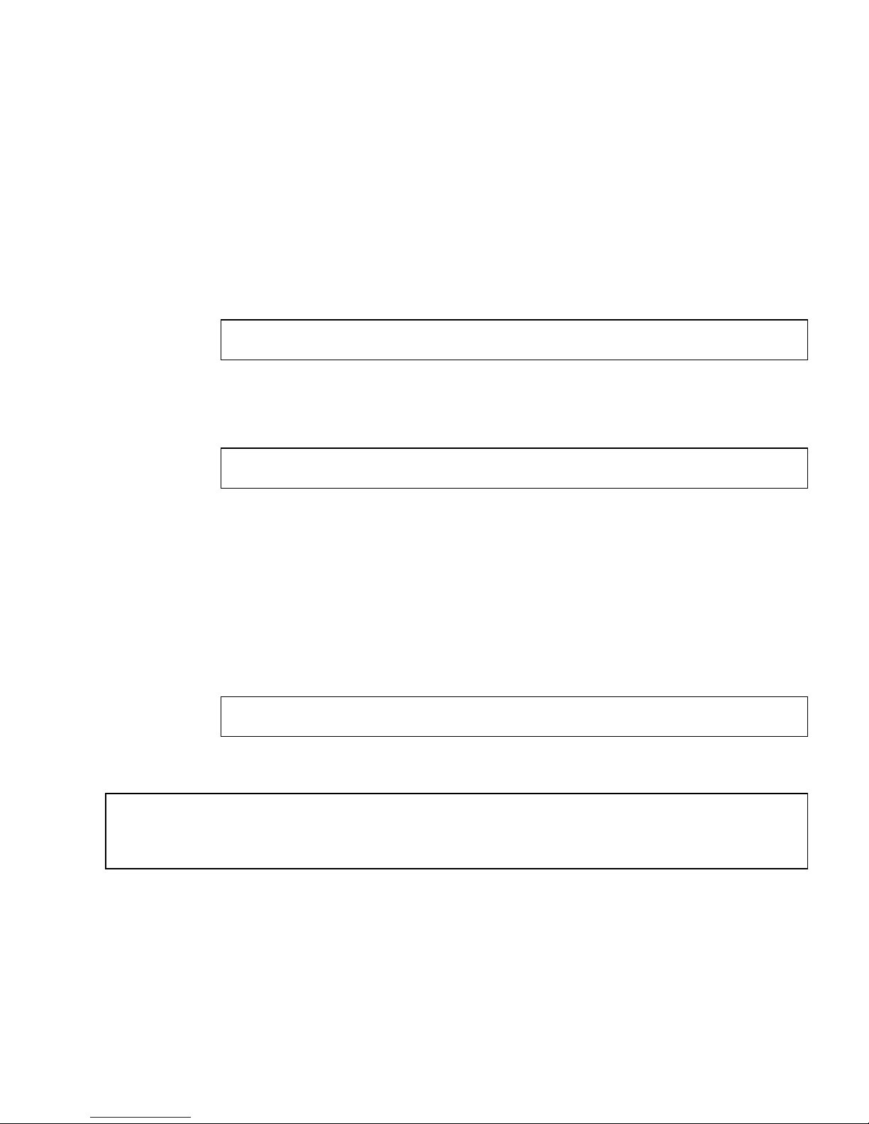
1. Shut down your system and display the OpenBoot prompt (ok) using the
procedures described in the Solaris Handbook for Sun Peripherals or your system
service manual.
For example, you can shut down the system using the shutdown command:
# /usr/sbin/shutdown -y -g10 -i0
Refer to the shutdown(1m) man page for more information.
2. Perform a reconfiguration book by typing the following at the OpenBoot prompt:
ok boot -r
Automatic Configuration
Follow this procedure to use the saipconfig utility to configure the SunSAI/P
interfaces on your system automatically.
1. Log onto to your system console as superuser (root).
2. To start the saipconfig utility, type:
# /etc/opt/SUNWconn/bin/saipconfig
3. Answer yes (y) to accept the default configuration.
The installation has detected 1 SunSAI/P serial adapter.
Would you like to automatically install the default configuration? y
Chapter 5 Device Driver Installation 19
Page 34

At this point, the saipconfig utility will configure the SunSAI/P interfaces
automatically. When saipconfig has finished configuring the interfaces, you will
see this message:
Configuration Completed.
Manual Configuration
Use the saipconfig utility to configure the SunSAI/P adapters on your system
manually. The utility will ask you a series of questions about how you want to
customize the adapters. After you have answered these questions, the utility will
reconfigure the driver software.
1. Log onto to your system console as superuser (root).
2. To start the saipconfig utility, type:
# /etc/opt/SUNWconn/bin/saipconfig
3. To configure the adapters manually, answer no (n) to this question:
The installation has detected 1 SunSAI/P serial adapter.
Would you like to automatically install the default configuration? n
The saipconfig utility will ask you questions about how you want to configure the
SunSAI/P interfaces.
This script installs the Sun PCI Serial Asynchronous Interface
driver :
This script also installs the information needed by Solaris to use
the additional ports available through this driver. Depending upon
your system, the driver may support up to 12 Host Adapters.
Press <CR> to proceed or "Q" to quit:
4. Press the Return key to configure your driver software.
20 SunSAI/P User’s Guide • November 1998
Page 35

5. Type the number of SunSAI/P adapters you want to configure on your system:
How many adapters do you wish to install (1-12)?
For each adapter that you specified in Step 5, you will be asked the questions shown
in Step 6 and Step 7.
6. Decide if you want to enable interrupts on the SunSAI/P adapter.
Type “y” to disable interrupts (the default value), or type “n” to enable interrupts,
on the adapter.
Note – We recommend that you use the default setting of disabled interrupts.
Configuring adapter 1.
Adapter type is 8-port PCI Async Intelligent Adapter.
8-port adapter:
In order to reduce response time to small packets (latency), it
may be helpful to enable interrupts on the adapter. However,
doing this will significantly increase driver CPU usage on your
Solaris system. By default, interrupts are disabled.
To enable interrupts, answer no.
Do you want to keep interrupts disabled on the adapter? (y/n)?
Chapter 5 Device Driver Installation 21
Page 36

7. Type “y” if you are satisfied with this adapter’s configuration.
You have selected the following configuration for adapter 1:
Adapter Type: 8-port PCI Async Intelligent Adapter.
Module Port Names
--------------------------1 term/a000 - term/a007 -- also /dev/cua/axxx
Interrupts disabled.
Is this configuration acceptable (y or n)?
Type “n” if you are not satisfied with the configuration.
Is this configuration acceptable (y or n)? n
Hit <CR> to re-configure adapter #1:
Press the Return key to return to Step 6.
After answering these questions for all of the SunSAI/P adapters on your system,
saipconfig will configure the interfaces automatically. When saipconfig has
finished configuring the interfaces, you will see this message:
Configuration Completed.
22 SunSAI/P User’s Guide • November 1998
Page 37

Creating New Devices
Devices have been created in /dev, giving the operating system the information to
use the additional ports.
The device driver will support up to 12 SunSAI/P adapters, depending upon your
system.
The devices are named according to the following convention:
TABLE 5-1 Format Used For Port Names
Format Description
/dev/term/ Directory path for dial-in devices.
/dev/cua/ Directory path for dial-out devices.
a - z, A - Z Module letter ID.
000 - 007 Port Number. For example, for the first board, the module letter and
port numbers will be a000 - a007. For the second board, they will
be b000 - b007.
Note – See Chapter 6 for more information about TTY device names.
Chapter 5 Device Driver Installation 23
Page 38
Enabling the New Ports
Please refer to your Solaris System Administration Guide, under the Peripherals Setup
section, for the details on how to enable serial ports.
Note – The System Administration Guide is shipped with the Solaris operating
environment, and it is available on the http://docs.sun.com/ website.
The following example shows how to set up serial ports for use with terminals:
1. Connect terminals to the ports (using a null modem, if necessary) and test the
connections to each terminal by entering the following command for each port
added:
# date > /dev/cua/a000
(Assuming the terminal is connected to a000.)
Please note that in the step above, the date command is used as a simple test, to
provide text output that can be redirected; there is no other significance to date in
this test.
■ If the date appears on the terminal screen, the device is properly connected.
■ If the date does not appear on the terminal screen, then that terminal is not
receiving data; check the power, cables, connections, and so on.
■ If nonsense characters are printed on the terminal screen, check the baud rates,
data bits, stop bits, and parity setting on your terminal.
Once you can redirect output to a terminal with the test above, perform the
following steps to enable that port:
2. Log onto the console as super-user (root).
3. Type (on a single command line):
# pmadm -a -p zsmon -s a000 -fu -i root -v ‘ttyadm -V‘ \
-m "‘ttyadm -d /dev/cua/a000 -l 9600 -s /usr/bin/login‘"
This will enable the port suitably for a terminal.
Note – Ports may also be enabled through the Solaris admintool program. Refer to
the System Administration Guide for more information.
24 SunSAI/P User’s Guide • November 1998
Page 39
Viewing the Man Pages
The SunSAI/P man pages are installed in the /opt/SUNWconn/man/ directory.
Before you can view the man pages, you will need to add this directory to your
MANPATH environment variable. The location of the MANPATH variable will depend
on which UNIX shell you are using.
Editing the C Shell Environment
1. Examine your $HOME/.login and $HOME/.cshrc files to locate the MANPATH
variable.
2. Using a text editor, add this line to the end of the file that contained the MANPATH
variable.
setenv MANPATH “/opt/SUNWconn/man/:$MANPATH”
If neither of these files contain this variable, add this line to the end of one of the
files, or contact your system administrator for assistance.
setenv MANPATH “/opt/SUNWconn/man/”
3. Use the source command on the file you edited to make the changes effective in
your current window.
For example, if you added the MANPATH line to the .login file, you would type:
% source $HOME/.login
Note – If you log out and then back into to your system, you will update the
MANPATH variable in all command windows and shells.
Chapter 5 Device Driver Installation 25
Page 40

Editing the Bourne or Korn Shell Environments
1. Using a text editor, add these two lines to the end of the $HOME/.profile file.
MANPATH=/opt/SUNWconn/man:$MANPATH
export MANPATH
If this file did not already contain this variable, add these lines to the end of the file,
or contact your system administrator for assistance.
MANPATH=/opt/SUNWconn/man
export MANPATH
2. Make the changes effective in your current window.
$ . $HOME/.profile
Note – If you log out and then back into to your system, you will update the
MANPATH variable in all command windows and shells.
Viewing the Man Pages
Once you have added the /opt/SUNWconn/man/ directory to your MANPATH
variable, you can use the /usr/man command to view these SunSAI/P man pages:
■ saip(7d)
■ saipconfig(1m)
■ saipd(1m)
■ saipdl(7d)
■ sitty(1)
■ spm(1m)
26 SunSAI/P User’s Guide • November 1998
Page 41
Un-Installing the Device Driver
Enter the following commands to un-install the device driver software:
1. Log onto the console as super-user (root).
2. Enter the following command:
# /usr/sbin/pkgrm SUNWsaip SUNWsaipu
3. You will see:
This package contains scripts which will be executed with super-user
permission during the process of removing this package.
Do you want to continue with the removal of this package [y,n,?,q] y
Answer “y”. The packages containing the driver and associated utilities will now be
removed from the system. In the event that some of the ports were open when
pkgrm was initiated, the unloading of the driver will fail. In this case it will be
necessary to reboot to complete the driver removal.
Chapter 5 Device Driver Installation 27
Page 42

28 SunSAI/P User’s Guide • November 1998
Page 43

CHAPTER
6
TTY Devices
This device driver supports two different device types on each line. On line “a000”,
where “a” refers to the first SunSAI/P board, and “000” refers to first line (port) on
that board, there are two devices:
/dev/term/a000
Dial-in TTY device, used for terminals, modems, printers, laboratory equipment,
etc.
This device is a traditional UNIX port with modem control. It requires Data
Carrier Detect (DCD) to be high before it will operate.
When used with a modem, the port will wait for carrier before sending out the
login: prompt, so the user is greeted properly upon making a connection.
When used with a terminal or other device, it is usually wise to wire the
SunSAI/P DCD signal to the terminal's DTR (Data Terminal Ready) line. When
the terminal is turned on, the system outputs a login: prompt. When the
terminal is turned off, any associated jobs are killed, and the user is logged out.
/dev/cua/a000
Dial-out TTY device. This is the same as /dev/term/a000 with the exception
that Data Carrier Detect need not be present to open the device. Once a
connection is established and DCD becomes active, standard devices behave in
the same way as modem devices-subsequent loss of the Data Carrier Detect signal
will cause the jobs to be killed and the user will be automatically logged off.
29
Page 44

30 SunSAI/P User’s Guide • November 1998
Page 45

CHAPTER
7
Setting Terminal Options with the
sitty Utility
sitty is a utility program that sets and displays the terminal options for the
SunSAI/P.
The sitty command must be run each time the machine is booted if non default
settings are required for certain ports. Usually, the best way to do this is by adding
sitty commands to your system initialization file (you can put them in a text file in
the /etc/rc2.d directory, and give the file a name such as /etc/rc2.d/S99saip
or /etc/rc2.d/S99sittystuff; refer to the Solaris System Administration Guide
for details). Alternatively, you may include the sitty command sequence in your
.login or .profile files. Your system administrator can help you edit these files.
The full pathname for the command is /opt/SUNWconn/bin/sitty.
The format is:
sitty [-a] [option(s)] [< ttyname]
With no options, sitty displays all SunSAI/P special driver settings, modem
signals, and all standard parameters for the TTY device referenced by standard
input.
Command options are provided to change flow control settings, force modem
control lines, and display all TTY settings (see
are passed to stty(1) for interpretation.
TABLE 7-1). Any unrecognized options
31
Page 46

TABLE 7-1 sitty Options
Option Description
-a Display all of the unique SunSAI/P option settings, as well as all of
the standard TTY settings reported by stty -a.
ttyname Set and display options for the given TTY device, instead of
standard input. ttyname is the full pathname
(e.g. /dev/term/a000) of the device.
The following options specify transient actions to be performed immediately.
break Send a 250 MS break signal out on the TTY line.
flush Immediately flush (discard) TTY input and output.
flushin Flush TTY input only.
flushout Flush TTY output only.
The following options are “sticky”, which means that the effects continue until the system is
rebooted or until the options are changed.
[-]fastbaud Alter the baud rate tables, so that the following baud rate changes
take place: 50=56700, 75=76800, 110=115200 , 200=230000,
300=76800, 600=115200, 1200=230000, and 1800=28800.
For example, 50 baud becomes 57,600 baud, 75 baud becomes 76,800
baud, and so on.
[-]forcedcd Disable [re-enable] carrier sense, so the TTY may be opened and
used even when carrier is not present.
[-]altpin Switches the function of the DSR and the DCD inputs on the,
modular connector, so that DCD is available when using an 8-pin
RJ-11 connector instead of the 10-pin RJ-45 connector.
edelay n Sets the number (n) of milliseconds of delay between the time the
first character arrives after a period of no characters and notification
of its arrival to the host. This delay is also referred to as the wakeup
rate between the host adapter software (FEPOS) and the host device
driver. This has the advantage of reducing host overhead by
allowing the host to process larger blocks of incoming data.
Larger edelay values result in more characters being sent in a
given time period. This will reduce host processor overhead and
increase overall system throughput. Smaller edelay values result in
fewer characters being sent in a given time period. This will
increase character response time and increase host processor
overhead.
32 SunSAI/P User’s Guide • November 1998
Page 47

TABLE 7-1 sitty Options (Continued)
Option Description
The default value for edelay is 100. This is a good value for normal
TTY activity like typing. For some applications like uucp,
decreasing the edelay value may increase character throughput,
but will result in increased system overhead. For applications
receiving continuous input at high speeds, increasing edelay will
result in lowering host overhead and increasing overall system
throughput. A value of 250 is reasonable.
The following options specify actions which are not “sticky”, meaning that the changes are
reset when the device is closed, and that the device will use the default values the next time
it is opened.
stopout Stop output exactly as if an xoff character was received.
startout Restart stopped output exactly as if an xon character was received.
stopin Activate flow control to stop input.
startin Release flow control to resume stopped input.
[-]dtr Raise [drop] the DTR modem control line, unless DTR hardware
flow control is selected.
[-]rts Raise [drop] the RTS modem control line, unless RTS hardware flow
control is selected.
[-]rtspace Enable [disable] RTS hardware input flow control, so RTS drops to
pause remote transmission.
[-]ctspace Enable [disable] CTS hardware output flow control, so local
transmission pauses when CTS drops.
[-]dsrpace Enable [disable] DSR hardware output flow control, so local
transmission pauses when DSR drops.
[-]dcdpace Enable [disable] DCD hardware output flow control, so local
transmission pauses when DCD drops.
[-]dtrpace Enable [disable] DTR hardware input flow control, so DTR drops to
pause remote transmission.
For more information, refer to the sitty(1), stty(1), ioctl(2), termio(7i),
and terminfo(4) man pages.
Chapter 7 Setting Terminal Options with the sitty Utility 33
Page 48

34 SunSAI/P User’s Guide • November 1998
Page 49

CHAPTER
8
Sun Port Manager
Sun Port Manager (SPM) is a software tool which provides a means to monitor the
status of the Front End Processor/Operating System (FEP/OS), which is the onboard software run by the SunSAI/P.
SPM also shows the status of the individual ports on a module by displaying a
simulated modem status register. Each of the eight supported EIA-232 signals is
displayed, along with input and output flow control status.
SPM is installed automatically when you install this device driver, and can be run
from any terminal on the system.
Using SPM
To run the Sun Port Manager, enter the following command from any terminal, or
the system console:
spm [-l logfile]
The -l logfile option specifies the file path for screen dumps. If this option is not
specified, the default log file path is /tmp/spmlog. The Sun Port Manager is fully
documented in context-sensitive help screens.
35
Page 50

36 SunSAI/P User’s Guide • November 1998
Page 51

APPENDIX
A
Error Messages
The following error messages are generated by the device driver:
WARNING: PCI SAI/8 memory allocation error. <2>
What it means: The operating system would not allocate memory to the driver.
Action to take: Adjust kernel resources. Reboot.
WARNING: PCI SAI/8 not resetting. <3>
What it means: The board doesn’t respond to reset.
Action to take: Make sure the board is fully seated in the slot. Potential hardware
problem.
WARNING: PCI SAI/8: No memory at 0xXX <4>.
What it means: The driver cannot read the board's dual ported memory.
Action to take: Make sure the board is fully seated in the slot. Potential hardware
problem.
WARNING: PCI SAI/8: port X failed diagnostics <5>.
What it means: The driver encountered an error executing on-board BIOS.
Action to take: Potential software problem.
WARNING: PCI SAI/8 FEPOS not functioning. <7>
What it means: The driver encountered an error executing on-board FEPOS.
Action to take: Potential software problem. Potential hardware problem.
37
Page 52

WARNING: saip_driver attach(0): Can't get config info for PCI
saip8 (#0)
What it means: The driver found a board in the system that had not been
configured.
Action to take: De-install driver with pkgrm. Install driver with pkgadd. Either
use the auto-install option or select the appropriate number of boards.
38 SunSAI/P User’s Guide • November 1998
Page 53

APPENDIX
B
Specifications
Power Requirements
■ +5 VDC 5%:960 mA typical
■ +12 VDC 5%:80 mA typical
■ -12 VDC 5%:80 mA typical
■ +3.3 VDC 5%:20 mA maximum
Board Dimensions
■ Length: 6.875 inches
■ Width: 0.5 inches
■ Height: 4.2 inches
■ Weight: 6.1 ounces
Operating Environment
■ Ambient temperature: 10˚ C to 55˚ C
■ Relative humidity: 5% to 90%
■ Air movement: 30 CFM forced
■ Altitude: 0 to 12,000 feet
Serial Interface Surge Suppression
■ Threshold Voltage (TxD & RxD): 12 Volts
■ Threshold Voltage (Control Lines): 12 Volts
■ Response Time: Less than 10 nS
39
Page 54

40 SunSAI/P User’s Guide • November 1998
Page 55

APPENDIX
C
SunVTS Diagnostic Testing
The SunVTS™ software executes multiple diagnostic hardware tests from a single
user interface and is used to verify the configuration and the functionality of most
hardware controllers and devices. The SunVTS software primarily operates from a
user interface that allows you to control all aspects of the diagnostic test operation.
The saiptest diagnostic, which is shipped with the SunVTS software, checks the
functionality of SunSAI/P adapters. This diagnostic can be run from the SunVTS
user interface, or it can be run from the command line. Refer to the SunVTS Test
Reference Manual for more information about the saiptest test.
Refer to the SunVTS documents for detailed information about the SunVTS software.
These documents are available on the Solaris on Sun Hardware AnswerBook, which
can viewed on the Sun Documentation website
(http://docs.sun.com/).
TABLE C-1 SunVTS Documentation
Title Description
SunVTS User’s Guide Describes the SunVTS environment; starting and
controlling the various user interfaces.
SunVTS Test Reference Manual Describes each SunVTS test; provides various test
options and command-line arguments.
SunVTS Quick Reference Card Provides an overview of vtsui interface features.
The main features of the SunVTS environment include:
■ SunVTS kernel
The SunVTS kernel (vtsk) controls all facets of the SunVTS environment. When
activated, vtsk probes the hardware configuration of the system being tested and
responds to commands from vtsui and vtstty. vtsk coordinates the operation of
individual tests and manages the messages sent by these tests.
41
Page 56

■ SunVTS user interface
The SunVTS graphical user interface (vtsui) operates on the windowing system.
vtsui controls vtsk and allows you to set user options, start and stop tests, and
read log files.
■ SunVTS TTY interface
The vtstty TTY user interface controls vtsk from either a command shell or a
terminal attached to a serial port. Most options available in vtsui have equivalent
options in vtstty.
Note – Some of the saiptest tests require a EIA-232 loopback plug, which can be
ordered through Sun (part number: 540-1558).
42 SunSAI/P User’s Guide • November 1998
Page 57

Index
B
board dimensions, 39
boot -r command, 19
C
cables, 6 to 7
capacitance, 7
diagrams, 9, 11, 12
environment, 7
grounding, 6
modem, 9
printer
simple, 11
with DTR, 12
recommended length, 7
terminal
simple, 11
with DTR, 12
configuring terminals, 31
connecting peripherals, 9 to 12
connector box
connector pin assignments, 5
illustrated, 6
creating new devices, 23
customer assistance, 2
pin assignments, 5
declaration of conformity, v
device driver
see software
devices
DTE, 10
DTR, 12
naming convention, 23
tty names, 29
diagnostic, 41
dial-in devices, 23, 29
dial-out devices, 23, 29
directory structure, 16
DTE devices, connecting, 10
DTR devices, 12
E
EIA-232
cables, 6
connector, pin assignments, 5
enabling ports, 24
environmental specifications, 39
error messages, 18, 37 to 38
D
DB-25 connector, 6
chassis ground, 6
F
FCC class B notice, iii
Index 43
Page 58

H
hardware
board operation, 2
components, 1
connector box, illustrated, 6
features, 1
handshaking, 12
installing, 3 to 4
RAM, 2
RISC processor, 2
OpenBoot prompt, 19
P
peripherals, connecting, 9 to 12
ports
enabling, 24
numbers, 23
power requirements, 39
I
installing
hardware, 3 to 4
software, 14 to 17
J
jumpers, 3, 4
M
man pages
listed, 26
viewing
Bourne shell, 26
C Shell, 25
Korn shell, 26
memory
on-board RAM, 2
starting address, 4
window size, 4
modem cable, 9
null, 10
N
null modem cable, 10
O
on-board memory, 2
R
rc script, 18
ready/busy hardware handshaking, 12
rebooting the system, 19
reconfiguration boot, 19
regulatory compliance statements, iii
run control scripts, 18
S
saipconfig utility, 18
saiptest diagnostic, 41
serial interface surge suppression, 39
shutdown command, 19
sitty utility, 18, 31
options, 32
software
configuring, 18 to 22, 31
automatic, 19
manual, 20
dial-in devices, 23, 29
dial-out devices, 23, 29
directory structure, 16
error messages, 18, 37 to 38
handshaking, 10
installation, 14 to 15
man pages, viewing, 25
new devices, 23
removing old versions, 13
Sun port manager, 35
supported Solaris versions, 1
un-installing, 27
Solaris environment
44 SunSAI/P User’s Guide • November 1998
Page 59

supported versions, 1
specifications
board dimensions, 39
environment, 39
power requirements, 39
serial interface surge suppression, 39
SPM, 35
starting, 35
Sun port manager, 35
starting, 35
SunSolve website, 2
SunVTS diagnostic, 41
U
un-installing software, 27
Index 45
Page 60

46 SunSAI/P User’s Guide • November 1998
 Loading...