

Page 1
English
User’s Manual
SUN-OPM200 Series
Fiber Optic Power Meter
Table: SUN-UM-TE-OPM004 Version: A/0
All the trademarks mentioned in this manual are registered property of Sun Telecom.
The right to interpret this manual is reserved by Sun Telecom.
Page 2

Page 3
Fib e r Opt i c Sol u tio n s P ro v ide r i
NOTICE
Safety Sign:
When using the optical power meter, always take bask safety precautions to
reduce the harm for the testers, and injury to persons. All the safety sign
may not mark in this manual.
Warning: Prohibited misconduct and operation, to prevent any
improper conduct and operation of the damage.
Notice: notice the important information, notification, and
references, these notice information should be understood.
Safety sign on the instrument:
WEEE Sign: Users of electrical and electronic equipment from
private households should have the possibility of returning
WEEE at least free of charge.
Safety Advice
1. When the tester use Disposable alkaline batteries, do not
charge it. Ensure the correct polarity installation, when
replace the battery.
2. When the products are not in use, please remove the
batteries and kept separate to avoid instrument damage caused by
Page 4

F ibe r O p tic Sol u tio n s P rov i d er ii
battery leakage. If leakage occurred, Please do not touch.
3. To prevent electric shock, do not open the product case, only the
authorized qualified professionals can do the maintenance; Do not
expose the testers to rain or wet conditions, to avoid the risk of fire or
electric shock
4. Instruments used LCD screen. Do not fall the instrument. If the LCD is
seriously hit, it may cause fluid leakage. And please do not touch.
Page 5

Fib e r Op t ic So l ut i o ns P r ovi d er iii
Contents
Chapter 1: Standard configuration .......................................................................1
Chapter 2: Overview ............................................................................................1
Chapter 3: Specifications .....................................................................................2
Chapter 4: Function .............................................................................................3
Chapter 5 OPM Software ...................................................................................14
Chapter 6 Operation Instruction and Notes .......................................................31
Chapter 7 Troubleshooting ................................................................................51
Chapter 8 General Maintenance ........................................................................52
Chapter 9 Quality Warranty ...............................................................................52
Page 6
F ibe r O pti c S olu t ion s P rov i der 1/54
No.
Product
Unit
Quantity
1
Optical Power Meter
set
1
2
AA 1.5V Battery
pieces
3
3
Power Adapter
piece
1
4
Soft Bag
piece
1
5
USB Line
piece
1
6
USB Disk
piece
1
7
FC Adapter
piece
1
8
SC Adapter
piece
1
9
ST Adapter
piece
1
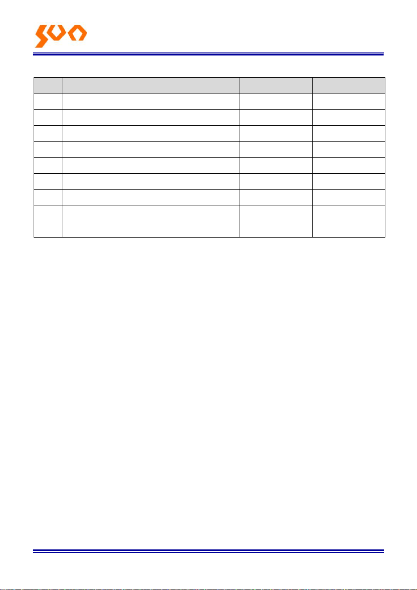
Chapter 1: Standard configuration
Chapter 2: Overview
SUN-OPM200 Series Handheld Optical Power Meter is a newly designed
fiber optic tester, which aims at the installation, engineering acceptance and
maintenance of fiber network.
Compared with other usual power meters, this power meter has more
functions when used with SUN-LS200 Series handheld optical light source,
like automatic wavelength identification, auto wavelength switching,
intelligent backlight, data savage via USB port.
Wave ID - Auto wavelength identification & switching
Frequency ID - Auto frequency identification
2 types of backlight modes, manual or outside light intensity, which
indicated by LED light red or blue color.
Intelligent backlight
1000 records storage or download via USB cable
USB communication port for saved testing records download
Reference power level can be set up and stored
User self-calibrating function
Auto-off function
Page 7
Fib e r Opt i c Sol u tio n s P ro v ide r 2/54
Model
SUN-OPM200-TC
SUN-OPM200-BC
Calibration Wavelength (nm)
850/1300/1310/1490/1550/1625
Detector type
InGaAs
Measurement Range (dBm)
-70 ~ +6
-50 ~ +26
Uncertainty (dB)
±0.15 (3.5%)
linearity (dB)
±0.02
Display resolution (dB)
0.01
Frequency ID (Hz)
270, 330, 1K, 2K
Wave ID (nm)
850, 1300, 1310, 1490, 1550, 1625
Date Storage Capacity
1000
Communication Port
USB
Standard Connector
FC /2.5mm universal
Optional Optical Connector
FC/SC/ST Interchangeable/2.5mm
Optional Optical Connector
LC/FC/SC/ST Interchangeable
Alkaline battery
3*AA, 1.5V
Power Adapter (V)
8.4
Battery Operating time (h)
200 without backlight
Operation Temperature (℃)
-10 ~ +60
Storage Temperature (℃)
-25 ~ +70
Dimension (mm)
175*90*44.5
Weight (g)
231
Up to 200hrs battery life
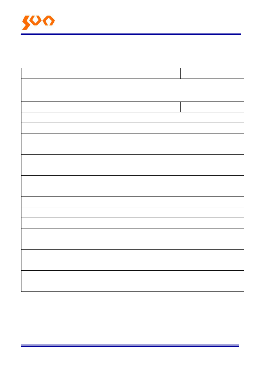
Chapter 3: Specifications
Remark: Battery operating time is based on the condition of the power off the backlight. If
power on the backlight continuously, the operation time will be shorter.
Page 8
Fib e r Opt i c Sol u tio n s P ro v ide r 3/54
Chapter 4: Function
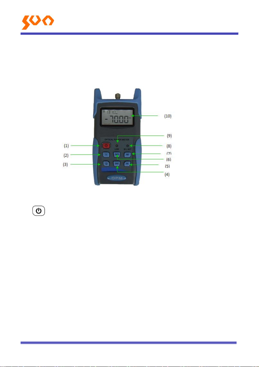
4.1 Front
4-1
(1) Power Key
ON/OFF the instrument
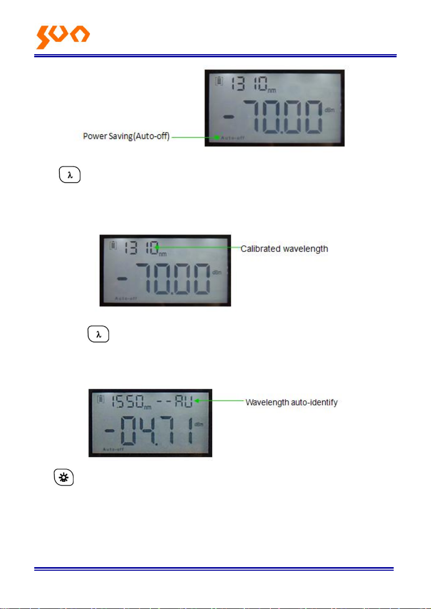
Power Saving setting: the unit will automatically shut off after 15 minutes idle
time, whatever in the condition of battery power supply or AC power supply.
Once choose this setting, the “auto-off” will display on the left bottom of the
screen. This power saving is the default setting, once open the power meter,
will enter into this mode. Shortly press the power button to deactivate auto
power saving mode.
Page 9
Fib e r Opt i c Sol u tio n s P ro v ide r 4/54
(2) Wavelength Selection/Wavelength Identify
Short press this key to switch the wavelength and display it on the top left of
the LCD screen, 1310nm is the default wavelength
Press the for 2 seconds, enter into wavelength auto-identify, on the
upper right of screen have “AU”, and also long press this key to quit this
function.
(3) Backlight Control (two mode of back light control, press this key to
choose one mode):
“LDR” the intelligent backlight control mode. Power meter will off/on the
backside in 15 seconds based on the outside light condition, and this is
Page 10
Fib e r Opt i c Sol u tio n s P ro v ide r 5/54
the default mode back light control key mode. Press to on/off the
back light
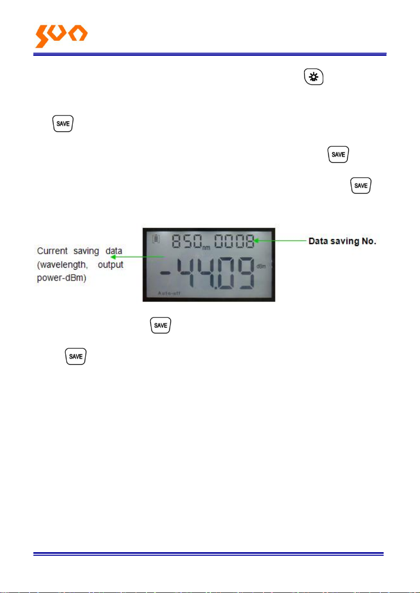
(4) Saving/Data-view Key.
Data-saving, can save data records no more than 1000. Press screen
will display the Data saving No., tip saving the data, double press to
confirm the saving.
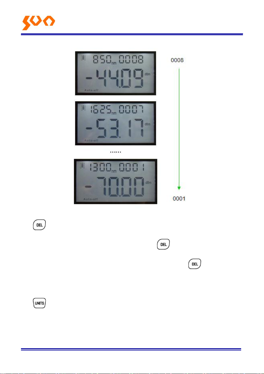
Data view. Long press to enter into the data view interface, short
press can view the data.
Page 11
Fib e r Opt i c Sol u tio n s P ro v ide r 6/54
(5) Delete/Cancel Key.
(1) Data Deletion. When view the data, press to delete the record.
(2) Cancel the saving. When in the saving mode, press to cancel the
current data saving.
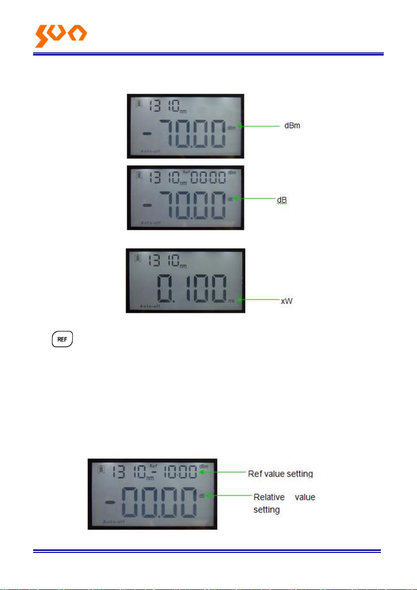
(6) Unit Switch Key
Press this key to switch between the absolute measurement (dBm), relative
measurement (dB) or xW of the optical power.
mW, dBm conversion: 10 log (mW) = (dBm)
Page 12
Fib e r Opt i c Sol u tio n s P ro v ide r 7/54
mW, uW and nW conversion: 1mW=103uW=106nW
(7) REF Setting:
To store the current power value as the reference value which will be
displayed on the top right of the LCD screen, at the same time the “Ref “ also
display on the right top. It will compare the current power with the reference
power and show the relative power value in dB.
The relationships between relative value (dB), absolute value (dBm), and
Ref value: relative value=|absolute value|-|Ref|
Page 13
Fib e r Opt i c Sol u tio n s P ro v ide r 8/54
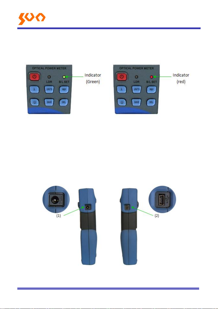
(8) “B/L SET” Backlight Indicator
Indicate backlight control mode. Green light indicate that “LDR” intelligent
backlight control mode, Red light indicate that key-control mode
(9) “LDR “ Intelligent Backlight Controller
In the intelligent backlight control mode, the controller will automatically
adjust the backlight with the outside light, which to save the power.
(10) Screen
Display the data and the instrument working mode.
4.2 Two sides
4-2 left side 4-3 right side
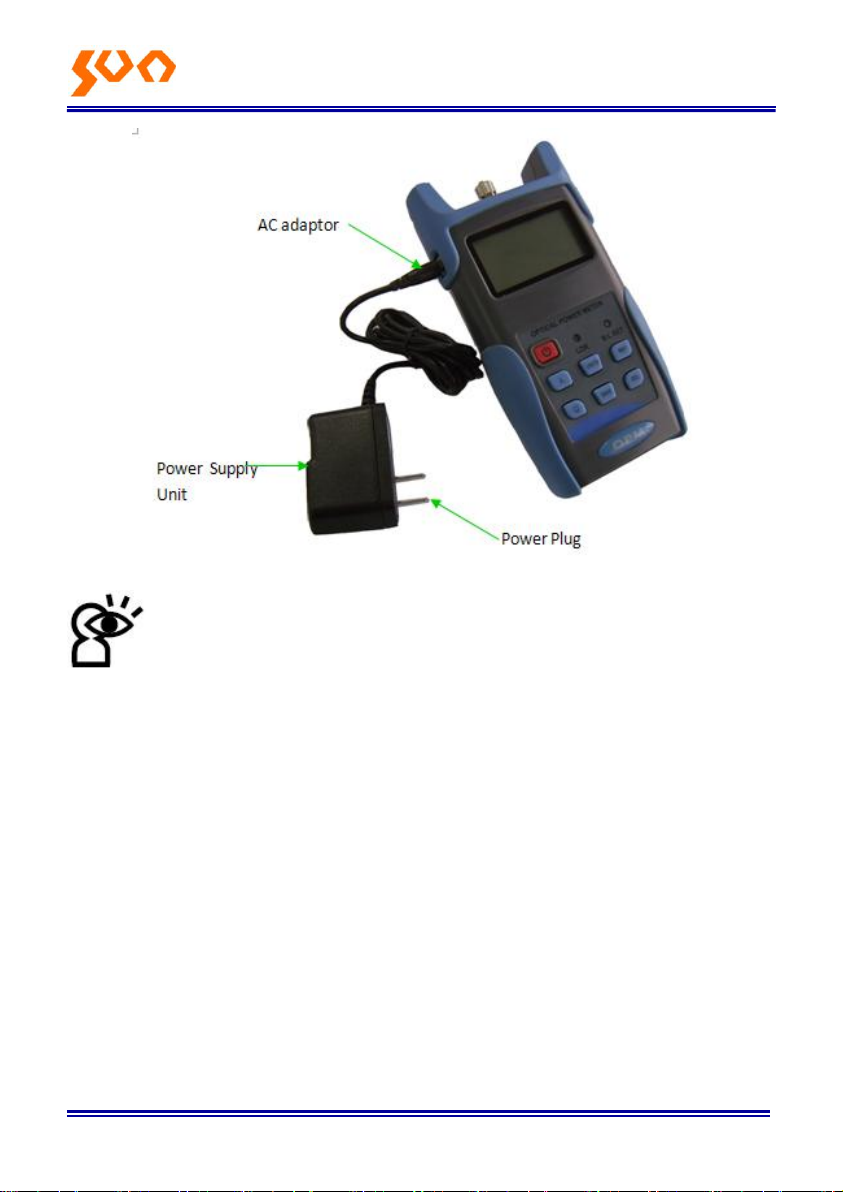
(1) Power Supply unit port: Can connect with the AC adaptor pic. 4-4.
Page 14
Fib e r Opt i c Sol u tio n s P ro v ide r 9/54
4-4
Notice: Please only use the power supply unit supplied with the
tester, use other kind of PSU may cause damage to the
instruments.
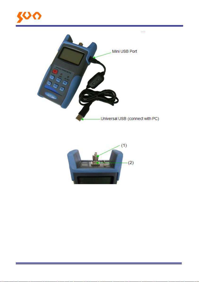
(2) USB Port.
Use the USB cable supplied to connect the Optical Power Meter to The USB
port on PC pic. 4-5.
Page 15
4.3 Top
Fib e r Op t ic So l u ti o n s Pro vid e r 10/54
4-5
4-6
(1) Dust Cap
In order to protect the optical connector, avoid damage on the connector, as
a result of that, when the tester not in use, please make sure that you place
the dust cap over the connectors.
(2) Optical Connector.
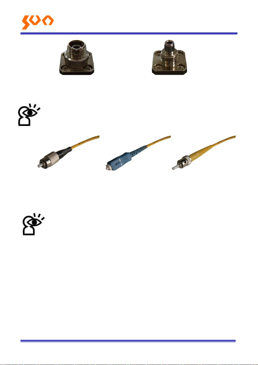
The standard of this power meter connector is Φ2.5mm PC universal
connector.pic. 4-7 & 4-8.Screw off the FC connector, it will turn to Φ2.5mm
universal connector.
Page 16
Fib e r Op t i c Sol u tio n s P ro v ide r 11/54
FC Patch Cord SC Patch Cord ST Patch Cord
4-7 FC connector 4-8 Φ2.5mm universal connectors
Notice: When change the optical connector, take care for the
connector and the end-face. FC connector can connect with FC
adaptor; Φ2.5mm universal connector can connect with FC, SC,
and ST adaptor. Pic 4-9
4-9
Notice: the tinny dust on the connector will affect the accurate of
the measurement value, so please clean the connector and the
patch cord end-face before the test.
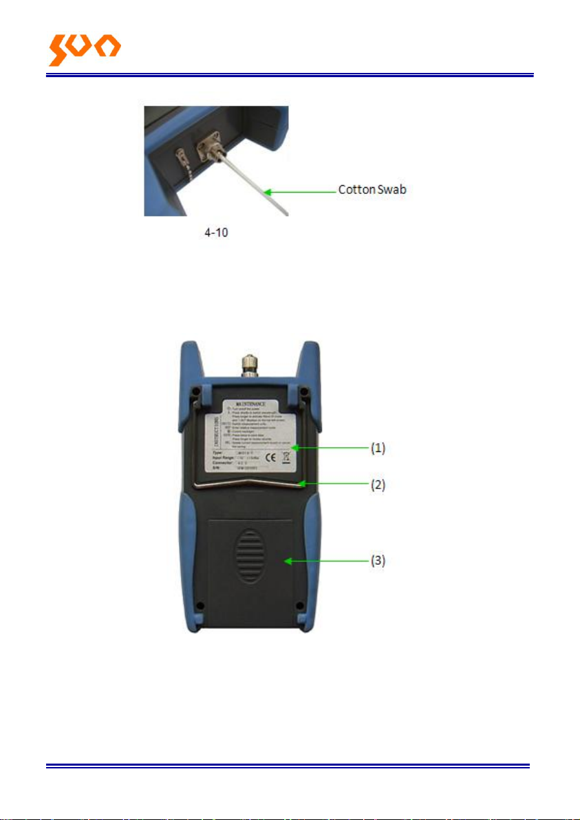
Use the alcohol and the cotton swab to clean the connector. Dip the cotton
swab with alcohol, insert the cotton swab in the connector, slightly rotating
the cotton swab, after that change a dry cotton swab and clean it again. Pic.
4-10.
Page 17
Fib e r Op t ic So l u ti o n s Pro vid e r 12/54
4.4 Backside
4-10
4-11
(1) Label
Content include the function, and the instrument information
(2) Bracket
Collapsible metal bracket, 0 ~ 90 degree can adjust.
Page 18

Fib e r Op t ic So l u ti o n s Pro vid e r 13/54
(3) Battery Pack: 3 pieces of 1.5V AA batteries.
Notice: When insert the batteries, take a note of their positive (+)
and negative (-) connector orientation. The negative battery
connector should be against the spring. And do recycle the
battery, do not throw the battery to the dustbin, or that will cause dangerous.
Page 19
F ibe r Opt i c So l uti o ns Pro vid e r 14/54
Chapter 5 OPM Software
5.1Install the device
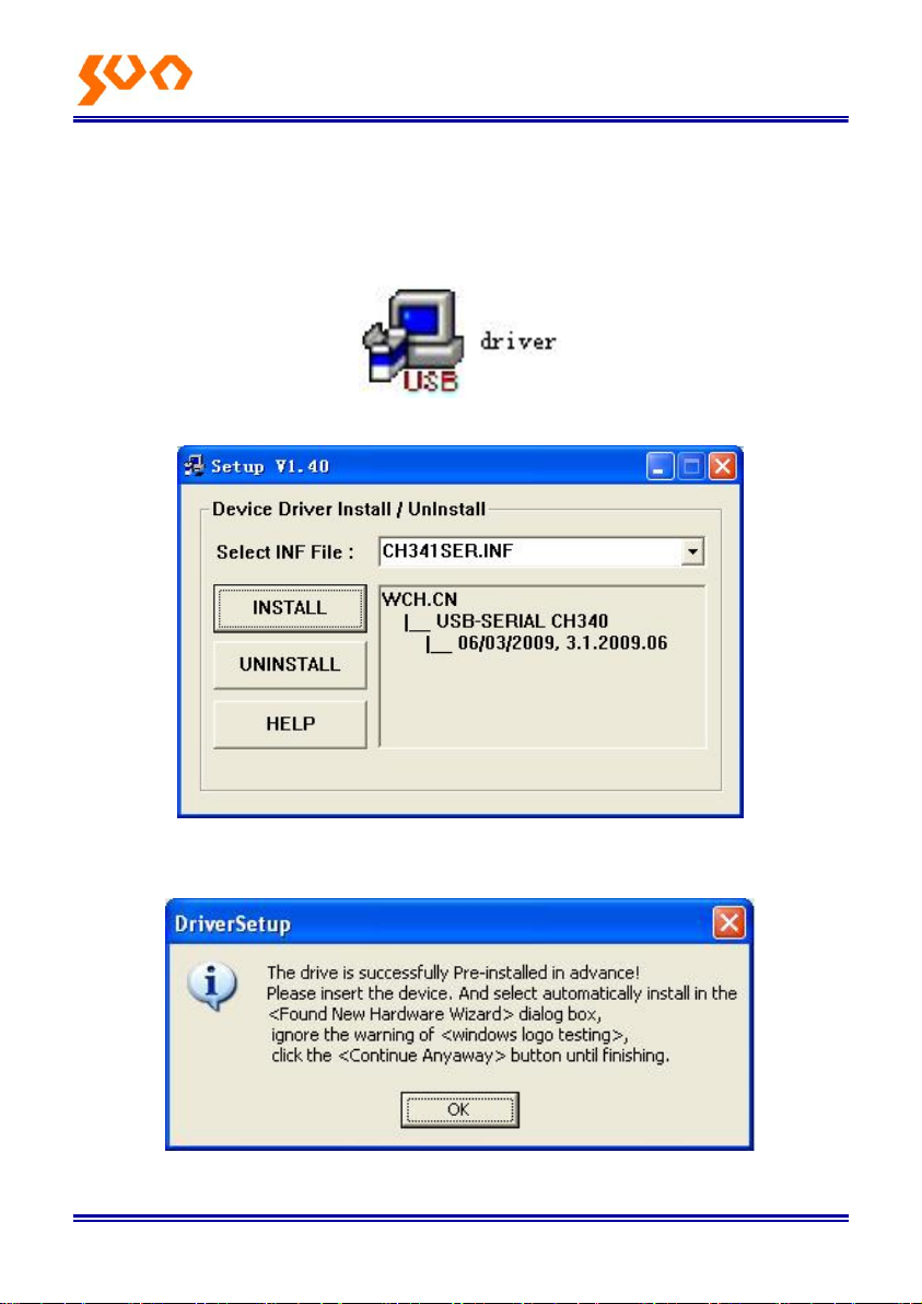
Run the software in the PC, find the “Driver.exe” as show in the below
Double click that “exe” program; the following will pop up (5-1).
5-1
Click “INSTALL”, after a few seconds, pop up 5-2.
5-2
Page 20
Fib e r Op t ic So l u ti o n s Pro vid e r 15/54
Press “OK” to exit this install interface. However the driver still haven’t install
yet, continue the following operation:
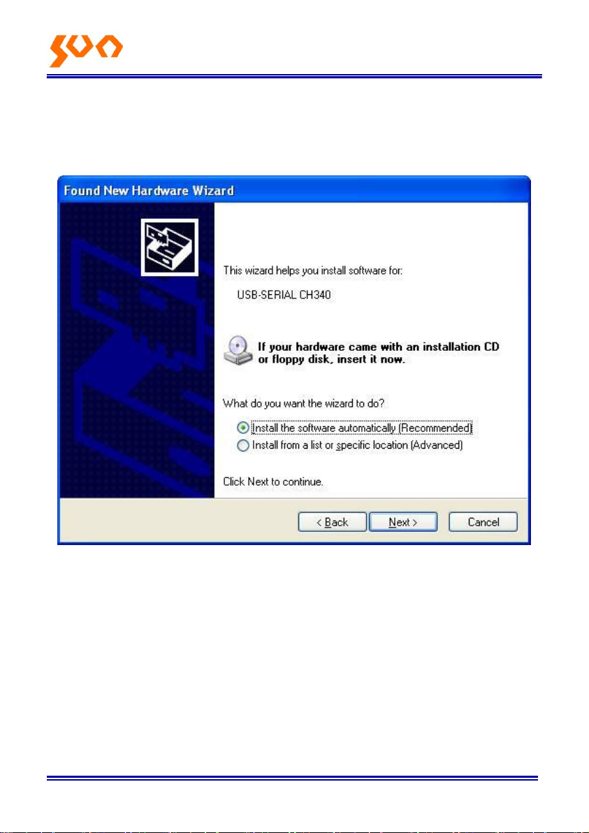
Use USB cable connect with power meter and the PC, switch on the
instrument, and pop up 5-3
Press “NEXT”, Pop up 5-4.
5-3
Page 21

Fib e r Op t ic So l u ti o n s Pro vid e r 16/54
Wait for a second, pop up 5-5.
5-4
Page 22
Fib e r Op t ic So l u ti o n s Pro vid e r 17/54
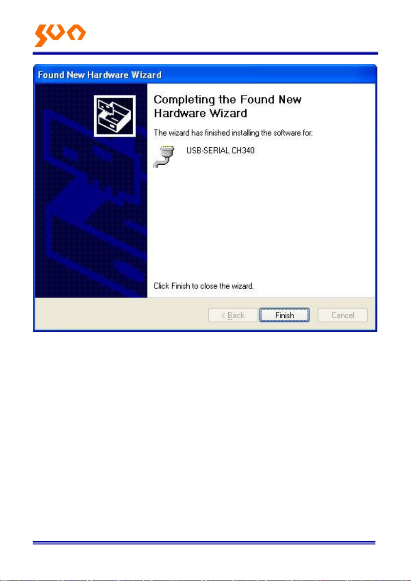
5-5
Press “Finish”, complete the deriver Installation.
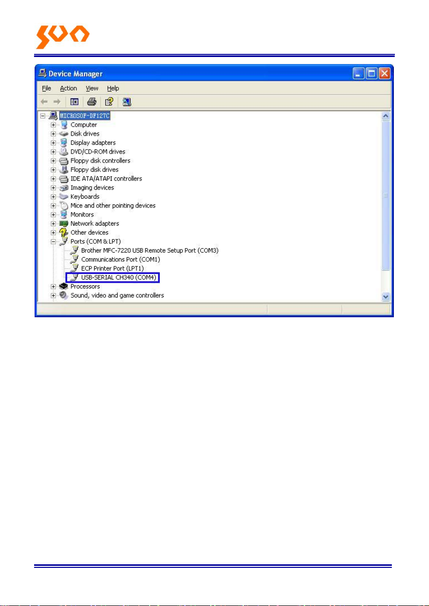
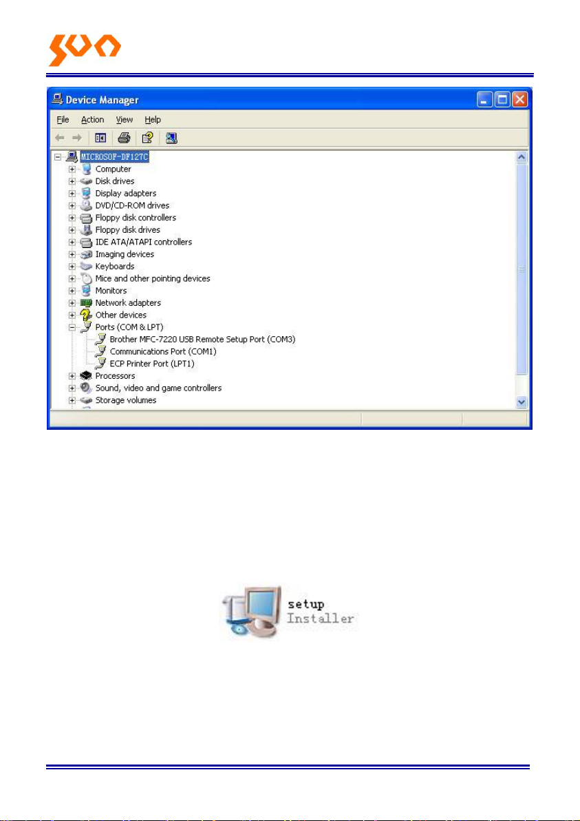
Please check if the installing is complete or not, to avoid the communication
problem when power meter connect with the PC. Open the “Device
Manager” (right click “My computer” choose “property”, pop up the property
interface, choose “hardware option”, click “Device Manager”), find the “Port
(COM and LPT)” if your interface is the same as the following pic 5-6, means
the install success. If the interface do not have “USB-SERIAL CH340” which
the same as 5-7, means the failure install, so need to re-install the devices.
Page 23
Fib e r Op t ic So l u ti o n s Pro vid e r 18/54
5-6
Page 24
Fib e r Op t ic So l u ti o n s Pro vid e r 19/54
5-7
After success install the devices, can switch off the power meter, and
disconnect the USB.
5.2 Install the application software
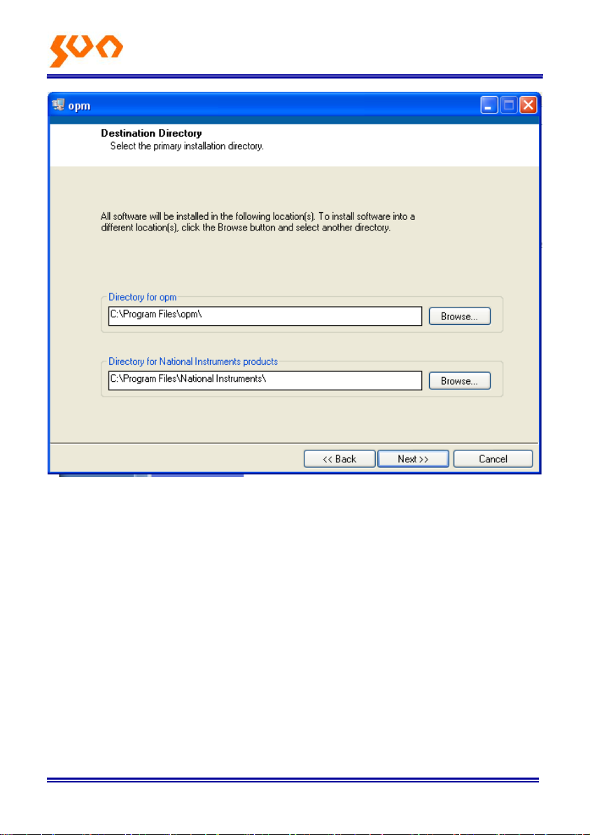
Run the CD in the PC; find the “setup” file
Double click this icon, pop up 5-8
Page 25
Fib e r Op t ic So l u ti o n s Pro vid e r 20/54
Press “Next “, and pop up 5-9.
5-8
Page 26
Fib e r Op t ic So l u ti o n s Pro vid e r 21/54
5-9
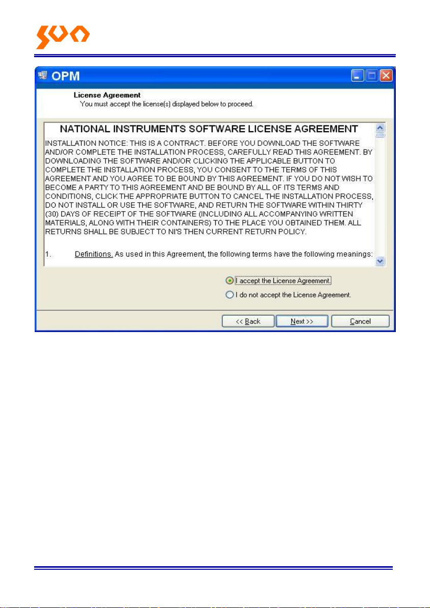
Choose “I accept …… “, Click “Next ", pop up 5-10.
Page 27
Fib e r Op t ic So l u ti o n s Pro vid e r 22/54
5-10
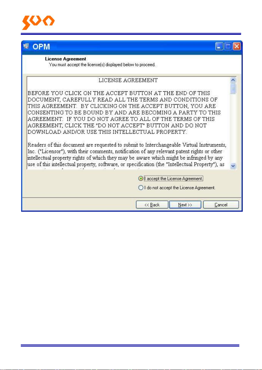
Choose “I accept ……” click “Next”, pop up 5-11.
Page 28
Fib e r Op t ic So l u ti o n s Pro vid e r 23/54
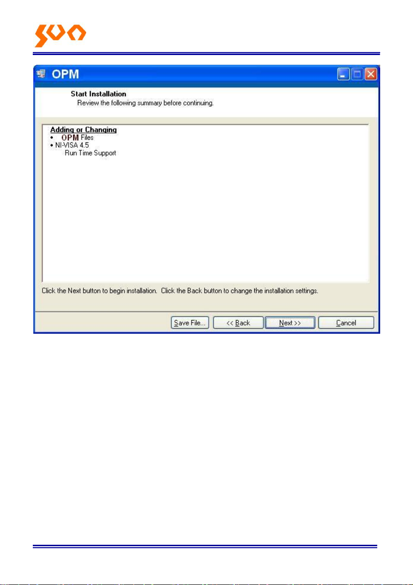
Click “Next “, pop up5-12.
5-11
Page 29
Fib e r Op t ic So l u ti o n s Pro vid e r 24/54
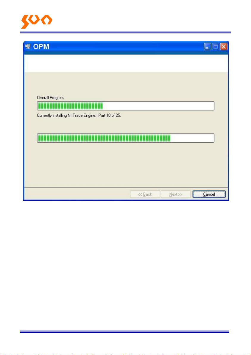
Wait for a seconds, Pop up 5-13.
5-12
Page 30
Fib e r Op t ic So l u ti o n s Pro vid e r 25/54
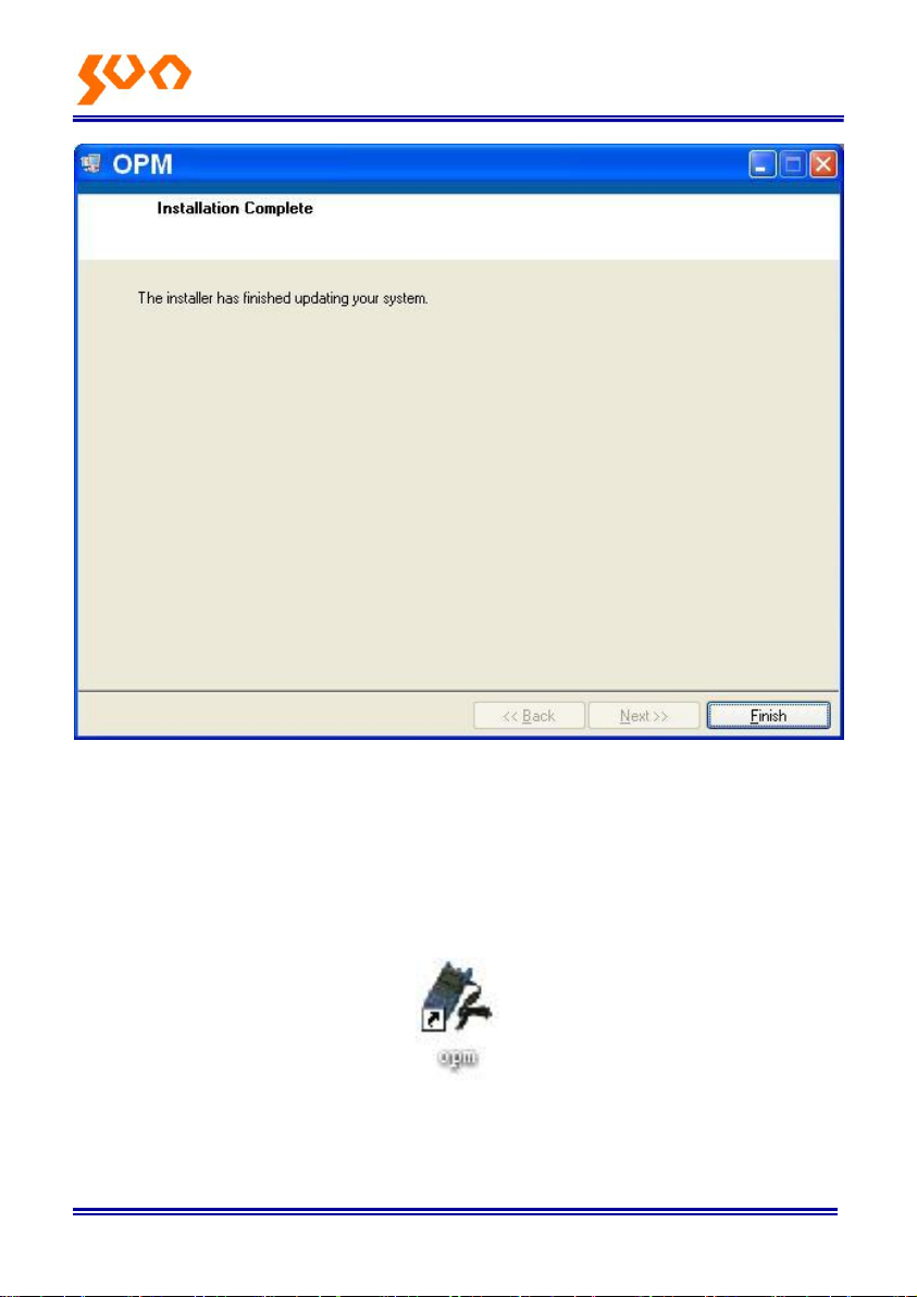
5-13
Click “Finish” to complete the installation.
5.3 Software function instruction
This software has two functions: data processing, and the instrument setting.
After finish the software, find the short cuts icon for this software.
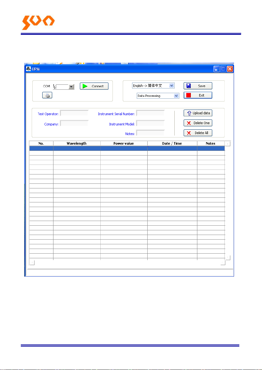
Double click this icon, open the software, and pop up the software interface
as pic 5-14, data processing is the default interface once opens the
software.
Page 31
Fib e r Op t ic So l u ti o n s Pro vid e r 26/54
5.3.1 Data Processing
5-14
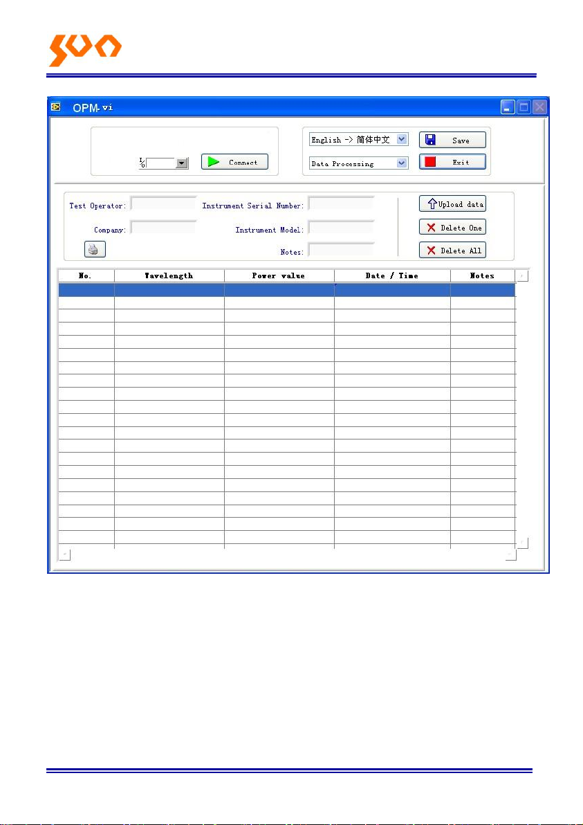
Data Processing interface include 4 parts.
(1) Manual
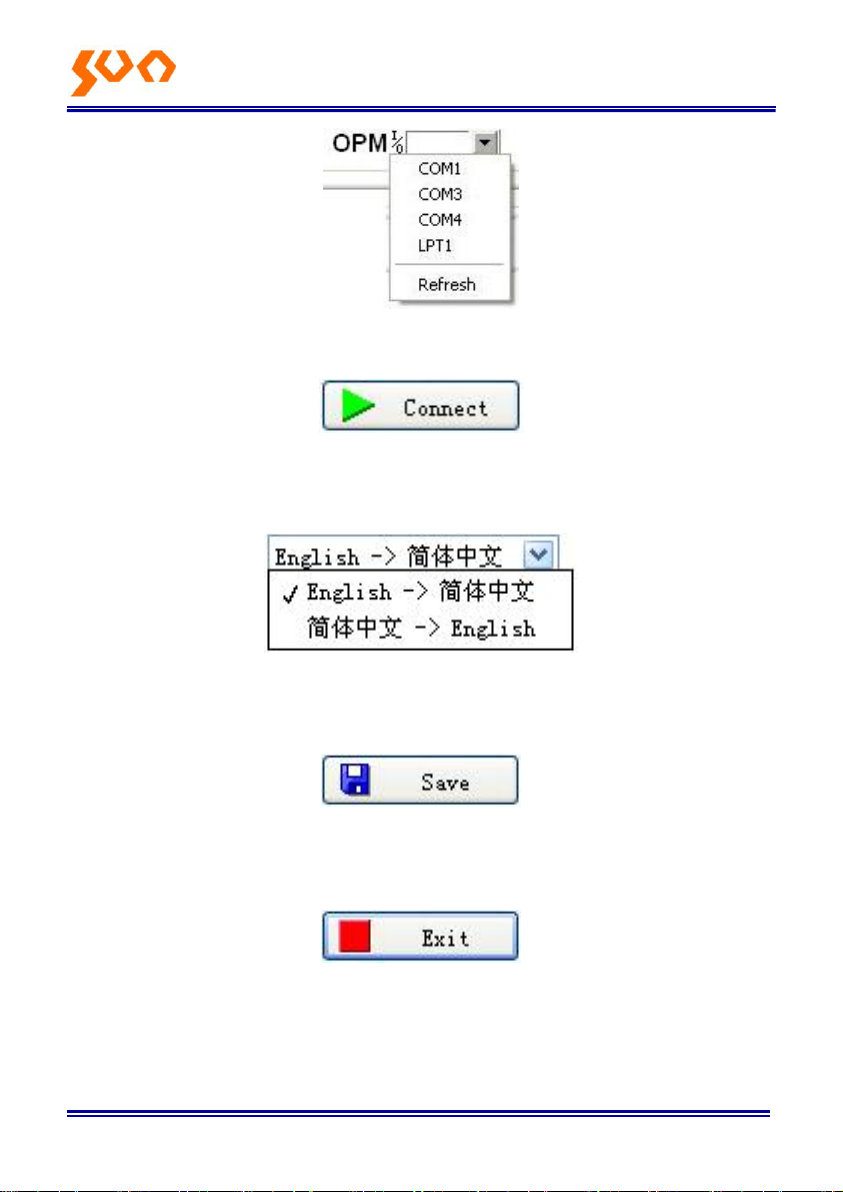
a) Port Option. Drop down the option box; choose the right port, which the
same port that the PC connected with the power meter.
Page 32
Fib e r Op t ic So l u ti o n s Pro vid e r 27/54
b) Connect icon, Connect the PC with the power meter, and communicate.
c) Language option, Drop-down the selection, Find the right language for
the user preference, Chinese/ English.
d) Function interface option: Two functions for option--data processing and
the instrument setting, drop-down the manual to choose.
e) Save button, save the current measurement data to the EXCEL file,
convenience for user to view and analysis the data on the PC.
f) Exit button, disconnect the communication, and close the software.
Page 33
Fib e r Op t ic So l u ti o n s Pro vid e r 28/54
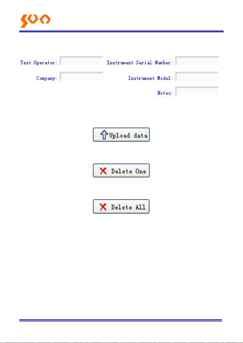
(2) Testing information form
Fill the information in blank
(3) Printing button to print the measurement value.
(4) Data process button
a) Upload the data to the PC; display the data on PC, for the user view.
b) Delete the choose data.
c) Delete all the data that saved in the instrument.
d) Data display area
To display the saved data of the instrument
Page 34
Fib e r Op t ic So l u ti o n s Pro vid e r 29/54
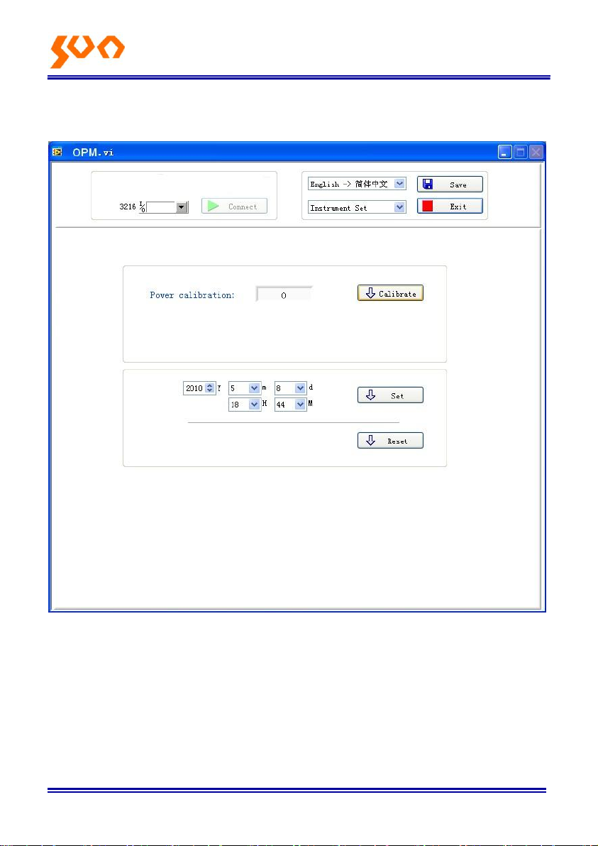
5.3.2 Power Meter setting
5-15
The Power Meter setting interface, pic. 5.3.2, which include 4 parts:
(1) Manu bar (Please refer description in data process interface)
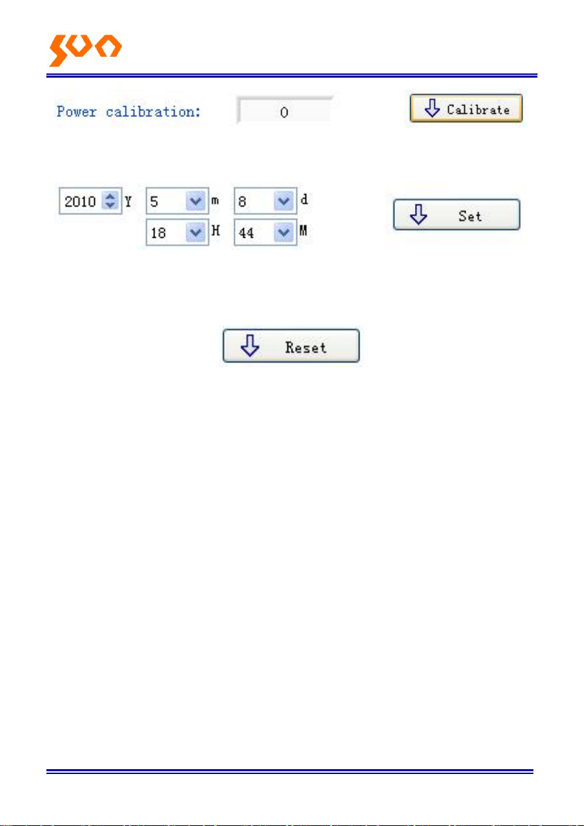
(2) Calibration, the user can do the self-calibration.
Page 35
Fib e r Op t ic So l u ti o n s Pro vid e r 30/54
(3) Time Setting.
(4) Recover the factory default setting. Power meter calibration recovers the
factory default setting.
Page 36
F ibe r Opt i c So l uti o ns Pro vid e r 31/54
Chapter 6 Operation Instruction and Notes
6.1 Powering the Optical Power Meter
The optical power meter can be battery powered or AC adaptor powered,
giving total flexibility for most testing sites and situations
6.1.1 AA battery
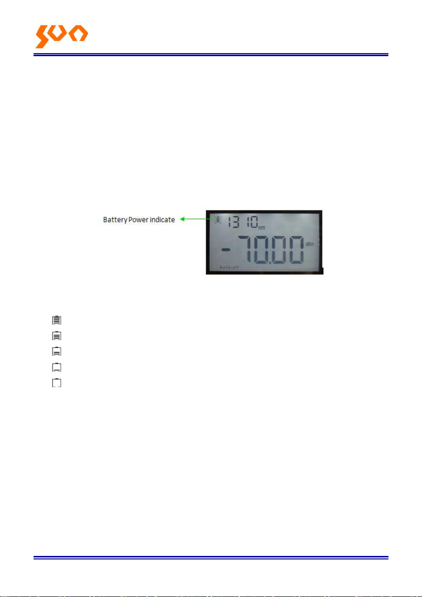
When use AA battery, the power meter will display the battery capacity on
the left top of the screen, refer to 6-1.
6-1
Power Grade:
left 70% ~ 100% electricity
left 40% ~ 70% electricity
left 30% ~ 40% electricity
left 20% ~ 30% electricity.
not enough electricity, left less than 20%, the power meter will forced
power off
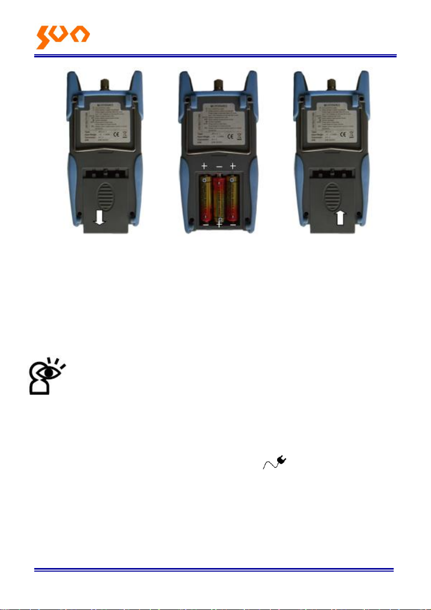
Fit the battery, 6-2
Page 37
Fib e r Op t ic So l u ti o n s Pro vid e r 32/54
6-2
Press the clip fastener on the battery compartment cover down. Remove the
battery compartment cover; remove all three batteries making a note of their
positive and negative connector orientation. The negative battery connector
should be against the spring. Insert 3 new 1.5VV AA batteries. Refit the
battery compartment cover. The clip fastener should click shut.
Notice: Make sure that you insert the batteries with their positive
and negative connectors correctly aligned.
6.1.2 Power Supply Unit
When the battery is used out, can use the power supply unit, and at this time
on the left top of the screen, there will be a sign ( 6-3).When the
battery in the power meter, and still have enough electricity, the tester will
choose AC power supply as the priority.
Page 38
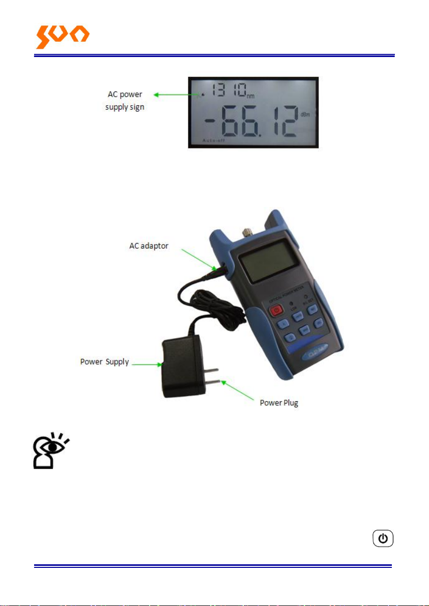
Fib e r Op t ic So l u ti o n s Pro vid e r 33/54
6-3
When use the AC adaptor, connect the power plug as pic 6-4, and insert to
the AC socket.
6-4
Notice: Please only use the power supply unit supplied with the
tester, use other kind of PSU may cause damage for the
instruments.
6.2 Power On the optical power meter
First of all insert the battery or the PSU, do not have any laser in, press
Page 39
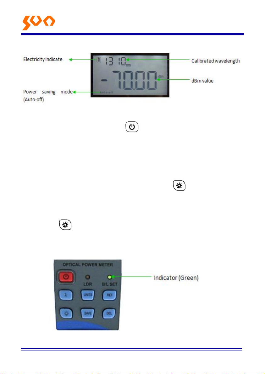
Fib e r Op t ic So l u ti o n s Pro vid e r 34/54
to open the tester, 6-5 is the opening interface
6-5
When the tester is standby, press key can cancel or choose auto-off
function. If auto-off function chosen, the “Auto-off” will display on the left
bottom of the screen.
6.3 Backlight setting
After turn on the optical power meter, long press to select backlight
control mode.
6.3.1 “LDR” Intelligent backlight control mode
Long press , “B/L SET “is green (6-6), after 10 seconds, the green
indicate off, the LDR the controller will automatically adjust the backlight
within 15 seconds with the outside light, which to save the power.
6-6
Page 40
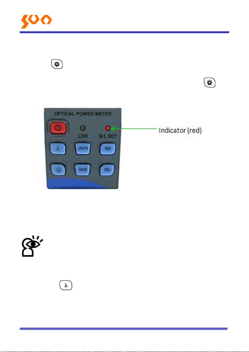
Fib e r Op t ic So l u ti o n s Pro vid e r 35/54
6.3.2 Choose the key control backlight mode.
Long press , “B/L SET “indicator turns to red (6-7), enter into key control
backlight mode, after 10 seconds the indicator off, short press can
ON/OFF the backlight.
6-7
6.4 Output power measurement
6.4.1 Take off the dust cap, connect with the patch cord.
Notice: Make sure the connector and the end-face of the patch
cord is clean, and take notice on the type of the patch cord, make
sure the correct patch cord are connected.
6.4.2 Select the wavelength
Shortly press to select the calibrated wavelength, and notice that if the
selected wavelength is not the same with the laser source wavelength,
which will cause the error of the measurement value. There are 6 calibration
wavelengths for selection.
Page 41
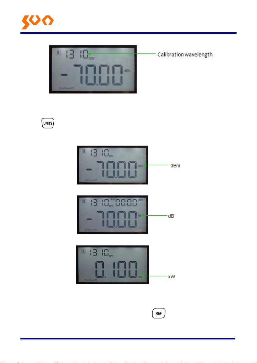
Fib e r Op t ic So l u ti o n s Pro vid e r 36/54
6-8
6.4.3 Unit Switch
Press to switch between the absolute measurement (dBm) and
relative measurement (dB) and xW of the optical power. (6-9)
6-9
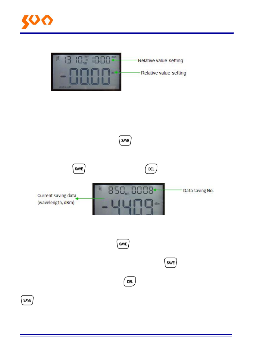
6.4.4 Relative value measurement
Each wavelength can set the Ref value, Press , set the current value as
the ref value, and automatically calculate out the relative value. (Right top of
Page 42
Fib e r Op t ic So l u ti o n s Pro vid e r 37/54
the screen display the “ref “and setting dBm value 6-10)
6-10
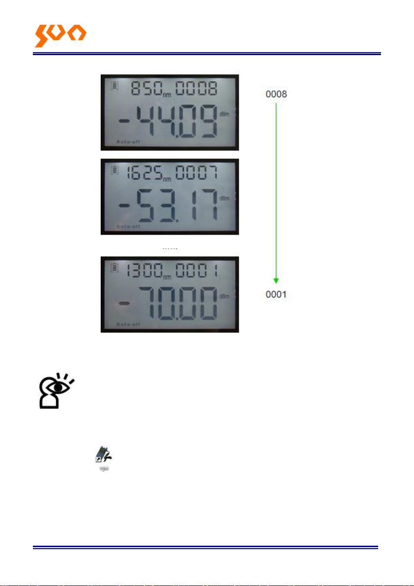
6.4.5 Data processing: Data storage and deletion.
The power meter has 1000 data records saving memory. When do the
output power measurement, press , at the right top of the screen will
display the data saving No. e.g.: “0008” (6-11), hint that if the data save or
not, double press confirm the saving, cancel saving.
6-11
Data view & delete. Long press to can view the saving record, the
screen will display the last saving data. Short press , can view the data
from the last record. (6-12) Press to delete the record, long press
exit the data view.
Page 43
Fib e r Op t ic So l u ti o n s Pro vid e r 38/54
6-12
6.5 Data Communication
Note: Before proceed the data communication, make sure the
driver and application software are installed successfully (Details
of installation please refer to chapter 5)
6.5.1 Open the software
Double click icon to open the software, user can choose the language
on request (Chinese or English), shown as figure 6-13.
Page 44
Fib e r Op t ic So l u ti o n s Pro vid e r 39/54
6-13
Connect Optical power meter with computer via USB cable, turns on the
power meter.
From the Device Manager: “Port (COM<P), we can see that power meter
port is “COM”, (6-14)
Page 45
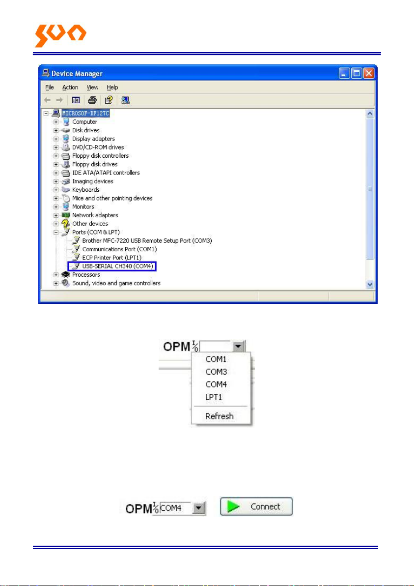
Fib e r Op t ic So l u ti o n s Pro vid e r 40/54
6-14
Therefore, choose “COM4” port shown as below figure (6-15)
6-15
Next click “Connect” as shown in below figure 6-16, will pop up a successful
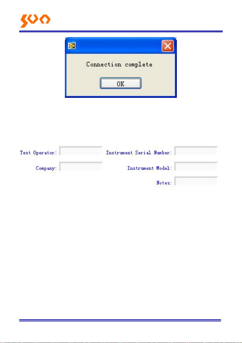
connection window shown as 6-17, click “OK” to finish the connection, the
unit can be communicated with computer properly.
6-16
Page 46
Fib e r Op t ic So l u ti o n s Pro vid e r 41/54
6-17
6.5.2 Data edit
Firstly, input the following basic information as shown on figure 6-18.
6-18
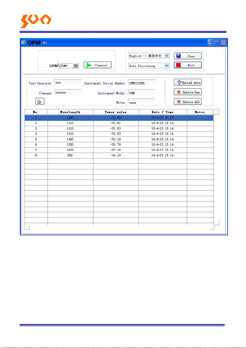
Then click “Upload data “, the saved data in the unit will be uploaded into
computer and shown as on below figure (6-19).
Page 47
Fib e r Op t ic So l u ti o n s Pro vid e r 42/54
6-19
Data edit at data display area, including data delete, data save and data
printing.
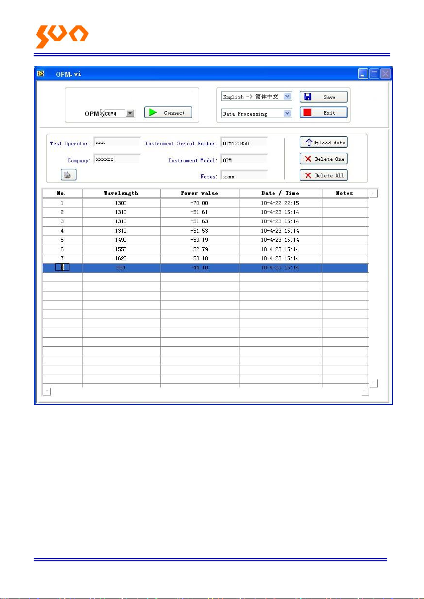
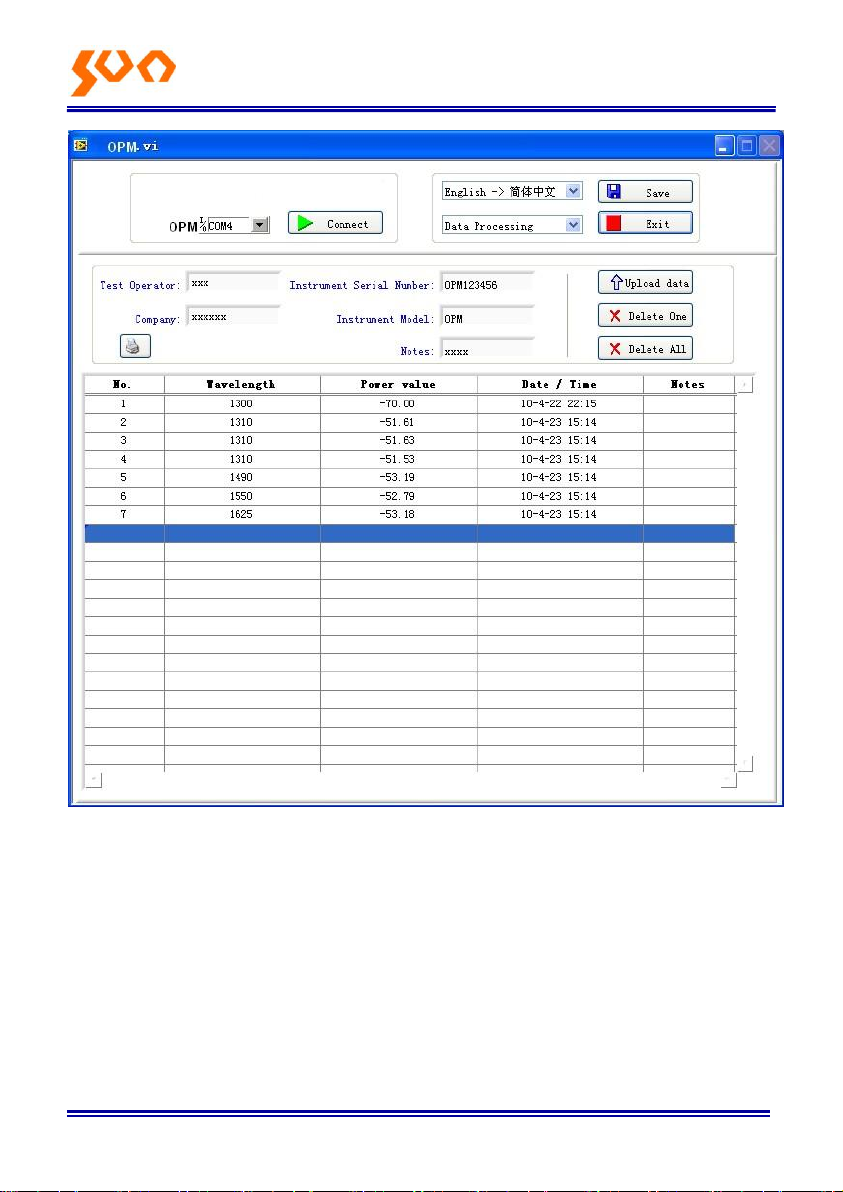
Select the required data, click “delete one “ to delete it from the sheet, as
shown on figure 6-20 and figure 6-21, in addition, the corresponding data
from the power meter also will be cleared accordingly.
Page 48
Fib e r Op t ic So l u ti o n s Pro vid e r 43/54
6-20
Page 49
Fib e r Op t ic So l u ti o n s Pro vid e r 44/54
6-21
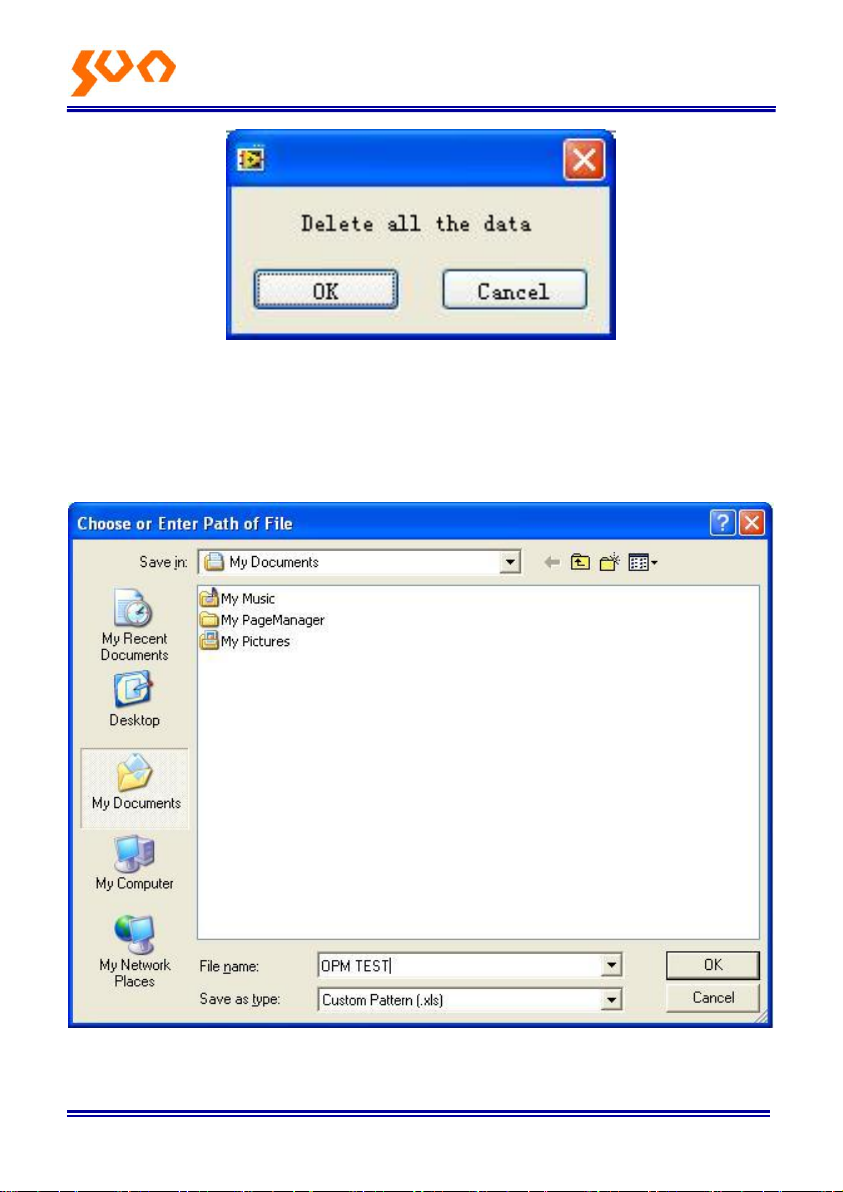
Click “Delete all “pop up a window shown as figure 6-22, click “OK “ to
delete all data, also will clear all saved data from the unit.
Page 50
Fib e r Op t ic So l u ti o n s Pro vid e r 45/54
6-22
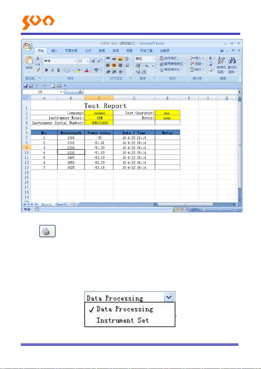
Click “Save” pop up a window shown as figure 6-23, input the file name,
choose the save path and press “ok” for storage. File will be with EXCEL
format and will pop up testing report automatically shown as figure 6-24.
6-23
Page 51
Fib e r Op t ic So l u ti o n s Pro vid e r 46/54
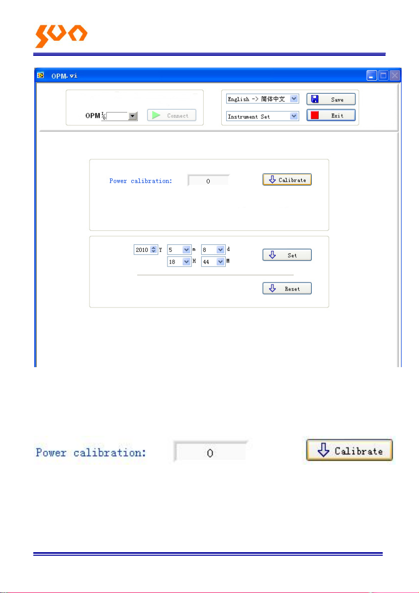
6-24
Click on the software, you can print testing report directly; you can
also print the testing report from Excel.
6.5.3 Function setting of the unit
Under function setting mode to switch the interface as shown on figure 6-25
and figure 6-26:
6-25
Page 52
Fib e r Op t ic So l u ti o n s Pro vid e r 47/54
6-26
There are there items can be set on the unit:
(1) Optical Power Calibration
6-27
Input the corresponding optical power and click “calibration “, users can
recalibrate the optical power by themselves.
Page 53
Fib e r Op t ic So l u ti o n s Pro vid e r 48/54
(2) Time setting
6-28
Input the corresponding date and time, and then click “Set “to modify the
time and date accordingly.
(3)Back to factory mode
6-29
Click “Reset”, the unit will be back to default setting (factory mode setting).
6.5.4 Close software
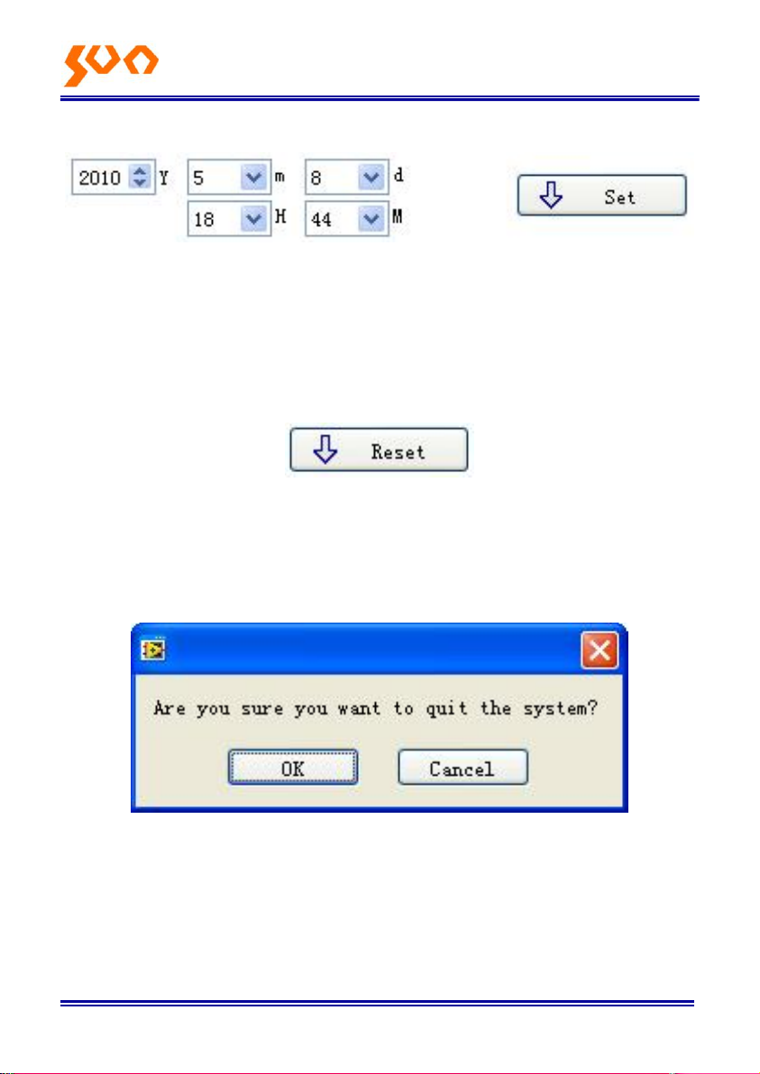
Click exit, pop up a window shown as below (figure 6-30):
6-30
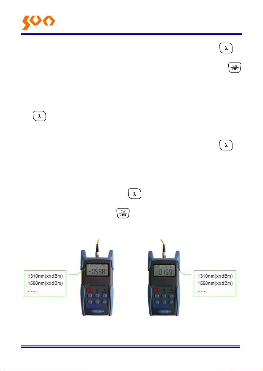
6.6 Wavelength Automatic Identification
Connect power meter with its same serials light source SUN-LS200
Series Light Source.
Page 54
Fib e r Op t ic So l u ti o n s Pro vid e r 49/54
Enable light source be Under “Wave ID” operation mode: press of
light source to emerge light output from light source. Hold down
for few seconds, light source will be enter into Wave ID mode, also
“—AU” will be shown on the upper right of LCD for an indication.
Enable power meter be under “Wave ID” operation mode: Hold down
for few seconds, power meter will be enter into Wave ID mode,
also “—AU” will be shown on the upper right of LCD for an indication.
Once the ID information is changed from light source (press to
change wavelength), after 3 to 5 seconds later, the detected information
on optical power meter also will be changed automatically according to
light source. Please refer to below figure (6-31) for easy understanding.
Exit Wave ID mode: Hold down again to exit Wave ID mode from
power meter and hold down again to exit Wave ID mode from light
source.
SUN-LS200 Light Source Power Meter
6-31
Page 55
Fib e r Op t ic So l u ti o n s Pro vid e r 50/54
6.7 Frequency detection
When use tone detection function, following requirements have to
be taken into account:
For A: Tone detection will be effective only with measurement
range between +6 ~ -40dBm.
For C: Tone detection can be worked only with measurement range
between +26 ~ -20dB, because the detected frequency will be unstable
when the power is weak.
How to act tone detection on Power Meter?
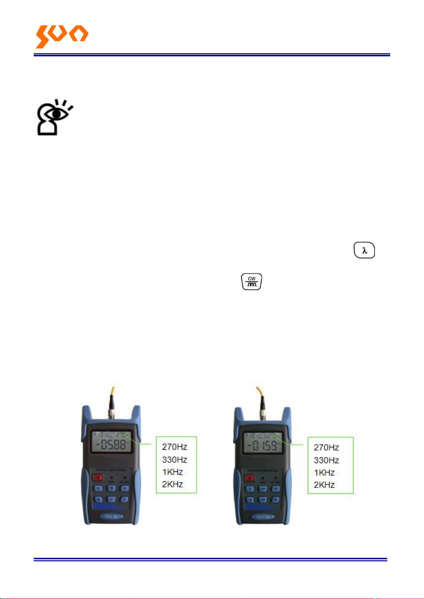
Connect power meter with its same serials light source SUN-LS200.
Output frequency from MATCHED optical light source: Press to
emerge light from the unit, press for very short second,
MATCHED light source will output frequencies of 270Hz, 330Hz, 1KHz,
2KHz accordingly, which will be shown on the upper right of the LCD in
MATCHED light source. In the mean time, the power meter will detect
the corresponding frequency automatically from MATCHED light source.
Please refer to below figure (6-32) for better understanding:
SUN-LS200 Light Source Power Meter
Page 56
Fib e r Op t ic So l u ti o n s Pro vid e r 51/54
Problems
Possible cause
Solution
Faint display on the
LCD screen
1. Power is off
2. The battery power
is too low
1. Press key.
2. Change the batteries
Inaccurate
measurements
1. Optical connector is
not clean.
2. incorrect fiber
connection
1. Clean optical connectors
2. Re-connect the fiber
6-32
Note:
Frequency ID and wave ID cannot be operated at the same time.
To avoid risk of serious eye damage, please do not look into the
optical port of laser source at any time.
6.8 Power off
Automatic power off: When auto-off function is activated, the unit will turn
itself off automatically after 10minutes idle time, whatever the power supply
is with alkaline batteries or is with power supply adaptor directly.
Manual power off: Under any operation mode, hold down for a few
seconds to turn the unit off.
Note: With either power off operation, the unit will store the last calibration
wavelength and backlight control mode automatically, which will be the
default setting when user turns unit on next time.
Chapter 7 Troubleshooting
Page 57

F ibe r Opt i c So l uti o ns Pro vid e r 52/54
Chapter 8 General Maintenance
Always keep the connector ports of your power meter are clean.
Do not use bad quality optical fiber connectors/adaptors; otherwise, it
will damage the interface of detector that will greatly affect the
performance of the unit.
Try to use only the adaptor supplied.
Once not in use, make sure dust-proof cap is placed properly over the
optical ports.
Carefully plug in/out for fiber connectors/adapters to avoid scratches on
the port of the power meter.
Keep regular cleanings on optical port of power meter; please clean with
cotton swabs supplied using alcohol properly.
Chapter 9 Quality Warranty
Details of warranty terms and conditions are given as below:
1) Sun Telecom warrants that Optical Power Meter will be free from
defects in material and workmanship for a period of 18 months. The date
will be started from the date of goods shipment.
2) If any defectives happened due to quality problems of the product during
the warranty period, SUN Telecom promises to repair or replace free of
charge. But the freight cost and related taxes will be shared by both
parties. SUN Telecom will pay the shipping cost from customer side to
our factory. And pay the import taxes related. Customer will pay the
shipping cost from our factory to customer side and its local import taxes
accordingly.
3) This warranty is limited to defects in workmanship and materials and
does not cover damages from accident, acts of god, neglect, wrong
usage or abnormal conditions of operation.
4) The company. will charge corresponding fees for the cost of materials,
Page 58

Fib e r Op t ic So l u ti o n s Pro vid e r 53/54
repair and shipping in conditions of below:
Defects occurred under normal use and service but out of the
warranty period.
Failures and damages occurred do not because of defects in
material and workmanship of products.
Failures and damages occurred because of failing to comply with the
Operation Instruction and necessary attention.
Abnormal conditions of operation or handling:
Such as artificial damage, or operating in abnormal conditions of like high
temperature, high voltage, humidity and etc., we will charge depend on the
actual failure rating.
Page 59

F ibe r Opt i c So l uti o ns Pro vid e r 54/54
An important message from Sun Telecom
We guarantee that any information you supply will remain confidential.
By returning this card, you will automatically be notified about updates,
modifications, and recalibration.
Warranty Registration Card
Serial Number:
Model Number:
Date of Purchase:
Company Name:
Company Address:
TEL: FAX:
E-mail:
Note: Please fax this note within one month from the date of receiving
units.
YOUR OPINION
Do you have any comments on the quality of this product or the service from
us?
Page 60

SHANGHAI SUN TELECOMMUNICATION CO., LTD.
Building No.145 Lane 666, Xianing Rd.
Jinshan Industrial Zone, Jinshan District
ShangHai, China 201506
Tel: +86 21 60138638 Fax: +86 21 60138635-401
E-mail: [email protected]
http://www.suntelecom.cn/
 Loading...