

Page 1

Sun Microsystems, Inc.
www.sun.com
Submit comments about this document at: http://www.sun.com/hwdocs/feedback
Sun Netra™CP3240 Switch
Installation Guide
Part No. 820-3251-13
September 2009, Revision A
Page 2

Please
Recycle
Copyright ©2009 SunMicrosystems, Inc., 4150 Network Circle, Santa Clara, California 95054, U.S.A. All rights reserved.
Sun Microsystems, Inc.has intellectualproperty rights relating to technology embodied in the product that is described in this document. In
particular,and withoutlimitation, theseintellectual property rightsmay includeone ormore of the U.S. patents listed at
http://www.sun.com/patents andone ormore additional patents or pending patent applications in the U.S. and in other countries.
This distributionmay includematerials developedby third parties.
Parts ofthe product maybe derivedfrom Berkeley BSD systems, licensed from the University of California. UNIX is a registered trademarkin
the U.S.and inother countries,exclusively licensedthrough X/Open Company, Ltd.
Sun, SunMicrosystems, the Sun logo, Solaris,Netra and the Netra logo are trademarksor registered trademarksof Sun Microsystems, Inc., orits
subsidiaries, inthe U.S.and othercountries.
Products covered by and information contained in this service manual are controlled byU.S. ExportControl laws and may be subject to the
export orimport lawsin othercountries. Nuclear, missile, chemical biological weapons or nuclear maritime end uses or end users, whether
direct or indirect, are strictly prohibited. Exportor reexport tocountries subjectto U.S.embargo or to entities identified on U.S. export exclusion
lists, including,but notlimited to,the deniedpersons andspecially designatednationals listsis strictlyprohibited.
Use ofany spare orreplacement CPUs is limited to repair or one-for-one replacementof CPUsin products exportedin compliancewith U.S.
export laws.Use ofCPUs asproduct upgrades unless authorized by the U.S. Government is strictly prohibited.
DOCUMENTATION IS PROVIDED "AS IS" AND ALL EXPRESS OR IMPLIED CONDITIONS, REPRESENTATIONS AND WARRANTIES,
INCLUDING ANY IMPLIED WARRANTY OF MERCHANTABILITY, FITNESS FOR A PARTICULARPURPOSE OR NON-INFRINGEMENT,
ARE DISCLAIMED, EXCEPT TO THE EXTENT THAT SUCH DISCLAIMERS ARE HELD TO BE LEGALLY INVALID.
Copyright ©2009 SunMicrosystems, Inc., 4150 Network Circle, Santa Clara, California 95054, Etats-Unis. Tous droits réservés.
Sun Microsystems, Inc.détient lesdroits de propriété intellectuels relatifs à la technologie incorporée dans le produit quiest décritdans ce
document. Enparticulier,et cesans limitation,ces droits depropriété intellectuelle peuvent inclure un ou plus des brevetsaméricains listésà
l’adresse http://www.sun.com/patents et un ou les brevets supplémentaires oules applicationsde brevet enattente auxEtats -Unis et dans les
autres pays.
Cette distributionpeut comprendre des composants développés par des tierces parties.
Des partiesde ceproduit pourront être dérivées des systèmes Berkeley BSD licenciés par l’Université de Californie. UNIX est une marque
déposée auxEtats-Unis etdans d’autres payset licenciéeexclusivement parX/Open Company, Ltd.
Sun, SunMicrosystems, le logo Sun, Solaris, Netra et le logo Netra sont des marques de fabrique ou des marques déposées de Sun
Microsystems, Inc., ou ses filiales, auxEtats-Unis et dans d’autres pays.
Ce produit estsoumis àla législationaméricaine enmatière de contrôle des exportations et peut être soumis à la règlementation en vigueur
dans d’autres paysdans ledomaine desexportations etimportations. Lesutilisations ,ou utilisateursfinaux, pourdes armesnucléaires, des
missiles, desarmes biologiqueset chimiquesou dunucléaire maritime, directement ou indirectement, sont strictement interdites. Les
exportations oureexportations vers les pays sous embargo américain, ou vers des entités figurant sur les listes d’exclusion d’exportation
américaines, ycompris, maisde manière nonexhaustive, laliste depersonnes quifont objetd’un ordre de ne pas participer, d’unefaçon directe
ou indirecte, auxexportations desproduits ou des services qui sont régis par la législation américaine en matière de contrôle des exportations et
la listede ressortissants spécifiquementdésignés, sontrigoureusement interdites. L’utilisation de piècesdétachées oud’unités centralesde
remplacement est limitée aux réparations ou à l’échange standard d’unités centrales pour les produits exportés, conformément à la législation
américaine enmatière d’exportation. Sauf autorisation par les autorités des Etats-Unis, l’utilisation d’unités centrales pour procéder à des mises
à jourde produits estrigoureusement interdite.
LA DOCUMENTATION EST FOURNIE "EN L’ETAT" ET TOUTES AUTRES CONDITIONS, DECLARATIONS ET GARANTIES EXPRESSES
OU TACITES SONT FORMELLEMENT EXCLUES, DANS LA MESURE AUTORISEE PAR LALOI APPLICABLE,Y COMPRISNOTAMMENT
TOUTE GARANTIE IMPLICITE RELATIVE A LA QUALITE MARCHANDE, A L’APTITUDE A UNE UTILISATION PARTICULIERE OU A
L’ABSENCE DE CONTREFACON.
Page 3

Please
Recycle
Page 4

Page 5

v
Contents
Preface xix
1. Getting Started 1–1
1.1 System Requirements 1–2
1.1.1 Connectivity 1–2
1.1.1.1 Hub Connectivity 1–2
1.1.2 Electrical and Environmental 1–2
1.2 Unpacking 1–4
1.3 Handling Switches 1–4
1.4 Connectors 1–5
1.5 Jumper Options 1–5
1.6 Switch and RTM Faceplates 1–6
1.6.1 Base 10/100/1000 Uplink Ports (RJ-45) 1–7
1.6.2 10/100 Management Port (RJ-45) 1–7
1.6.3 Serial Management Port (RJ-45) 1–7
1.7 RTM Airflows 1–7
1.7.1 RTM Airflow Requirements 1–7
1.7.2 RTM Pressure Drop Versus Airflows (Impedence Curves) 1–8
1.8 Removing and Installing Switches 1–10
1.8.1 Removing a Switch Set 1–10
Page 6

vi Sun Netra CP3240 Switch Installation Guide • September 2009
1.8.1.1 Removing a Switch From the Front of the Server 1–11
1.8.1.2 Removing a Rear Transition Module for a Switch 1–13
1.8.2 Installing a Switch Set 1–14
1.8.2.1 Installing the Rear Transition Module for a Switch 1–14
1.8.2.2 Installing a Switch 1–14
1.9 Switch LEDs 1–15
1.9.1 ATCA Board Status LEDs 1–15
1.9.2 Hot-Swap LED 1–16
2. Overview 2–1
2.1 Features 2–2
2.1.1 General 2–2
2.1.2 Base Interface 2–3
2.1.3 Fabric Gigabit Interface 2–4
2.1.4 AMC Sites 2–5
2.2 Switch Components 2–6
2.2.1 Broadcom StrataXGS 3 BCM56503 Ethernet Switch 2–6
2.2.2 Broadcom StrataXGS 3 BCM56800 Ethernet Switch 2–6
2.2.3 Broadcom BCM5464R and BCM5461S 10/100/1000Base-T Ethernet
PHY 2–6
2.2.4 Freescale PowerQUICC II MPC8247 Communications Processor
2–7
2.2.5 Pigeon Point BMR-H8S-AMCc AdvancedTCA IPMI Subsystem
2–7
2.3 Protocols, RFCs, and MIBs Support 2–8
2.3.1 FASTPATH Switching 2–8
2.3.1.1 Additional Layer 2 Functionality 2–9
2.3.1.2 System Facilities 2–9
2.3.1.3 Switching MIBs 2–10
2.3.1.4 Routing MIBs 2–10
Page 7

Contents vii
2.3.2 FASTPATH Routing 2–11
2.3.3 FASTPATH Quality of Service 2–12
2.3.3.1 DiffServ 2–12
2.3.3.2 Access Control Lists (ACLs) 2–12
2.3.3.3 Class of Service (CoS) 2–13
2.3.3.4 Quality of Service MIBs 2–13
2.3.4 FASTPATH Multicast 2–13
2.3.4.1 Multicast MIBs 2–14
2.3.5 FASTPATH IPv6 Routing 2–14
2.3.5.1 IPv6 Routing MIBs 2–15
2.3.6 FASTPATH Management 2–15
2.3.6.1 SSL 3.0 and TLS 1.0 2–16
2.3.6.2 SSH 1.5 and 2.0 2–16
2.3.6.3 Additional Management Features 2–16
2.4 Functional Diagrams and Port Maps 2–17
2.4.1 Switch 2–17
2.4.2 Rear Transition Modules (RTM)s 2–18
2.4.2.1 Copper RTM 2–19
2.4.2.2 Fiber Optic RTM 2–21
2.4.3 Base Fabric Switch Subsystem 2–23
2.4.4 Expansion Fabric Switch Subsystem 2–24
2.4.5 AdvancedMC Sites 2–25
2.4.5.1 AMC Port Maps 2–26
2.4.5.2 AMC Module Support by Site 2–30
2.4.5.3 AMC Port Restrictions for RTMs 2–30
3. Configuring Jumper Settings 3–1
3.1 Jumper Settings 3–2
3.1.1 P4 Cross-Connect Control 3–2
Page 8

viii Sun Netra CP3240 Switch Installation Guide • September 2009
3.1.2 P6(1-2) Fabric Zero Reset Configuration Word 3–3
3.1.3 P6(3-4) Base Zero Reset Configuration Word 3–3
3.1.4 P8(1-2) Base Write Protect 3–3
3.1.5 P8(3-4) Fabric Write Protect 3–4
3.1.6 P9 IPMC Firmware Program 3–4
3.1.7 P10(1-2) IPMC Reset 3–4
3.1.8 P10(3-4) IPMC FWE 3–5
3.1.9 P11(1-2) Forced-Board Enable 3–5
3.1.10 P11(3-4) IPMC Board Reset 3–5
3.1.11 P12(1-2) and P12 (3-4) EMI Ground to Logic Ground 3–6
3.1.12 P13 Serial Direction 3–6
3.2 Jumper Locations 3–7
4. Configuring Switch Software 4–1
4.1 IPMI Firmware Sensors 4–2
4.1.1 State Sensors 4–2
4.1.2 Threshold Sensors 4–4
4.2 uBoot 4–5
4.2.1 uBoot Console 4–5
4.2.2 E-Keying Control in uBoot 4–6
4.2.3 Serial-Baud Rate Control in uBoot 4–7
4.3 Linux 4–7
4.3.1 e-Keying 4–7
4.3.2 e-Keying Bypass 4–8
4.3.3 ATCA LEDs 4–8
4.4 Serial Select 4–8
4.5 Serial Location 4–9
4.5.1 Changing Serial Location from UBoot 4–9
4.5.2 Changing Serial Location from FASTPATH 4–9
Page 9

Contents ix
4.6 Boot Sequence 4–10
4.6.1 Boot Utility Menu 4–11
4.6.1.1 Load Code Update Package using TFTP/FTP 4–12
4.6.1.2 Erase Current Configuration 4–12
4.6.1.3 Erase Permanent Storage 4–12
4.6.1.4 Select Boot Method 4–12
4.6.1.5 Start Diagnostic Application 4–13
4.7 Primary and Backup Flash 4–13
4.8 Dual Firmware Images 4–13
4.8.1 Booting the Non-Active Image 4–13
4.8.2 Updating the Non-Active Image 4–14
4.8.3 Fabric 1G/10G Auto-negotiation 4–14
4.9 Network Boot 4–14
4.10 FASTPATH 4–18
4.10.1 Management Options 4–18
4.10.1.1 CLI 4–18
4.10.2 Basic CLI Commands 4–19
4.10.3 Logins and Prompts 4–20
4.10.3.1 CLI Defaults 4–20
4.10.3.2 Web Interface Defaults 4–20
4.10.3.3 SNMP Defaults 4–21
4.10.4 Secure Remote Access 4–21
4.10.4.1 SSH and SSL/TLS Keys 4–21
4.10.4.2 Enabling SSH and SSL 4–21
4.10.5 Default Settings 4–22
4.10.6 Port Ordering 4–22
4.11 Firmware Updates 4–24
4.11.1 Firmware List 4–24
Page 10

x Sun Netra CP3240 Switch Installation Guide • September 2009
4.11.2 Firmware Upgrades 4–24
4.12 Fiber Optic RTM Configuration 4–25
4.12.1 Module Support 4–25
4.12.2 Backplane Ports Versus RTM Optical Ports 4–25
4.12.3 10G Configuration for RTM Optical Port 4–25
4.12.4 1G Configuration for RTM Optical Port 4–26
A. Environment Specifications A–1
A.1 Electrical and Environmental A–2
A.1.1 Absolute Maximum Ratings A–2
A.1.2 Normal Operating Ranges A–2
A.2 Reliability A–3
A.3 Mechanical A–3
A.3.1 Board Dimensions and Weight A–3
B. Connectors B–1
B.1 Connector Assignments B–2
B.2 Connector Locations (Topside) B–3
B.3 ATCA Zone 2 P20 ZD Connector (J5) B–5
B.4 ATCA Zone 2 P21 ZD Connector (J4) B–6
B.5 ATCA Zone 2 P22 ZD Connector (J3) B–6
B.6 ATCA Zone 2 P23 ZD Connector (J2) B–7
B.7 ATCA Zone 2 P24 ZD Connector (J1) B–8
B.8 Serial RJ-45 Connector (J13 Top) B–8
B.9 Serial Cable B–9
B.10 10/100/1000Base-T RJ-45 Connector (J13 3rd, J13 Bottom) B–10
B.11 10/100Base-TX RJ-45 Connector (J13 2nd) B–10
B.12 ATCA Zone 3 RTM Connector Top (J8) B–11
B.13 ATCA Zone 3 RTM Connector (J7-Middle) B–11
Page 11

Contents xi
B.14 ATCA Zone 3 RTM Connector (J6-Bottom) B–12
C. Datasheet Reference C–1
D. Agency Certifications D–1
D.1 CE Certification D–1
D.2 NEBS/ETSI D–1
D.3 Safety D–2
D.4 Emissions Test Regulations D–3
D.4.1 EN 50081-1 Emissions D–3
D.4.2 EN 55024 Immunity D–3
D.5 Regulatory Information D–4
D.5.1 D.4.1FCC (USA) D–4
D.5.2 Industry Canada (Canada) D–5
Index Index–1
Page 12

xii Sun Netra CP3240 Switch Installation Guide • September 2009
Page 13

xiii
Figures
FIGURE 1-1 Switch and RTM Faceplates 1–6
FIGURE 1-2 Netra CP3240H-RTM-CU Airflow (Pa) 1–8
FIGURE 1-3 Netra CP3240H-RTM-CU Airflow (InchesH20) 1–8
FIGURE 1-4 Netra CP3240H-RTM-OP Airflow (Pa) 1–9
FIGURE 1-5 Netra CP3240H-RTM-OP Airflow (InchesH20) 1–9
FIGURE 1-6 Front Cable Management Bracket in Lower Position 1–11
FIGURE 1-7 Injector/Ejector on the Switch (Open Position) 1–12
FIGURE 2-1 Switch Functional Block Diagram 2–17
FIGURE 2-2 Copper RTM Functional Block Diagram 2–19
FIGURE 2-3 Fiber Optic RTM Functional Block Diagram 2–21
FIGURE 2-4 Base Fabric Switch Subsystem 2–23
FIGURE 2-5 Expansion Fabric Switch Subsystem 2–24
FIGURE 2-6 AMC Port Map Diagram 2–26
FIGURE 3-1 Switch Jumper Locations 3–7
FIGURE A-1 PCB Dimensions A–4
FIGURE B-1 Connector Locations (Topside) B–3
FIGURE B-2 ATCA Zone 1 Connector (J9) B–5
Page 14

xiv Sun Netra CP3240 Switch Installation Guide • September 2009
Page 15

xv
Tables
TABLE 1-1 Power Requirements 1–2
TABLE 1-2 Airflow Requirements 1–7
TABLE 1-3 ATCA Board Status LEDs 1–15
TABLE 1-4 Hot-Swap LED States 1–16
TABLE 2-1 Switch External Ports 2–18
TABLE 2-2 Zone 3 RTM Ports 2–18
TABLE 2-3 Copper RTM External Ports 2–20
TABLE 2-4 Copper RTM Port Restrictions 2–20
TABLE 2-5 Fiber Optic External RTM Ports 2–22
TABLE 2-6 Fiber Optic RTM Port Restrictions 2–22
TABLE 2-7 AMC Ethernet Port Availability 2–27
TABLE 2-8 AMC Site 1: AMC.0 Mid-size, AMC.2 Type E1, AMC.2 Type 5 (Optional), LED Module
Support 2–27
TABLE 2-9 AMC Site #2 AMC.0 Mid-Size, AMC.2 Type E1, AMC.2 Type 5, Double module support, LED
Module Support 2–28
TABLE 2-10 AMC Site 3: AMC.0 Mid-size, AMC.2 Type E1, Master Clock Generator Support, LED
Support 2–29
TABLE 2-11 AMC Modules by Site 2–30
TABLE 2-12 AMC Port Restrictions for Copper RTMs 2–30
TABLE 2-13 AMC Port Restrictions for Fiber Optic RTMs 2–30
TABLE 3-1 Switch Configuration Jumper Settings 3–2
TABLE 3-2 P4 Cross-Connect Jumper Settings 3–2
Page 16

xvi Sun Netra CP3240 Switch Installation Guide • September 2009
TABLE 3-3 P6 (1-2) Fabric Zero Reset Jumper Settings 3–3
TABLE 3-4 P6 (3-4) Base Zero Reset Jumper Settings 3–3
TABLE 3-5 P8 (1-2) Base Write-Protect Jumper Settings 3–3
TABLE 3-6 P8 (3-4) Fabric Write Protect Jumper Settings 3–4
TABLE 3-7 P9 IPMC Firmware Program Jumper Settings 3–4
TABLE 3-8 P10 (1-2) IPMC Reset Jumper Settings 3–4
TABLE 3-9 P10 (3-4) IPMC FWE Reserved Jumper Settings 3–5
TABLE 3-10 P11 (1-2) Forced-Board Enable Jumper Settings 3–5
TABLE 3-11 P11 (3-4) IPMC Board Reset Jumper Settings 3–5
TABLE 3-12 P12 (1-2) and P12 (3-4) Grounding Jumper Settings 3–6
TABLE 3-13 P13 Serial Direction Jumper Settings 3–6
TABLE 4-1 IPMI State Sensors 4–2
TABLE 4-2 0 4–2
TABLE 4-3 IPMI Sensor Logic 4–3
TABLE 4-4 IPMI Thresold Sensors 4–4
TABLE 4-5 uBoot Console Commands 4–6
TABLE 4-6 Basic CLI Commands 4–19
TABLE 4-7 Port Order List 4–22
TABLE A-1 Absolute Maximum Electrical and Temperature Ratings A–2
TABLE A-2 Normal Operating Electrical and Temperature Ratings A–2
TABLE A-3 Board Dimensions and Weight A–3
TABLE B-1 Connector Assignments B–2
TABLE B-2 ATCA Zone 1 Connector (J9) Pins B–4
TABLE B-3 ATCA Zone 2 P20 ZD Connector (J5) B–5
TABLE B-4 ATCA Zone 2 P21 ZD Connector (J4) B–6
TABLE B-5 ATCA Zone 2 P22 ZD Connector (J3) B–6
TABLE B-6 ATCA Zone 2 P23 ZD Connector (J2) B–7
TABLE B-7 ATCA Zone 2 P24 ZD Connector (J1) B–8
TABLE B-8 Serial RJ-45 Connector (J13-Top) B–8
TABLE B-9 Minimum Serial Cable Pinouts B–9
Page 17

Tables xvii
TABLE B-10 10/100/1000Base-T RJ-45 Connector (J13-3rd and Bottom) B–10
TABLE B-11 10/100Base-TX RJ-45 Connector (J13-2nd) B–10
TABLE B-12 ATCA Zone 3 RTM Connector (J8-Top)) B–11
TABLE B-13 ATCA Zone 3 RTM Connector (J7-Middle) B–11
TABLE B-14 ATCA Zone 3 RTM Connector (J6-Bottom) B–12
Page 18

xviii Sun Netra CP3240 Switch Installation Guide • September 2009
Page 19

xix
Preface
The Sun Netra CP3240 Switch Installation Guide describes the installation and
configuration of the Sun Netra CP3240 switch. This guide also includes information
about software, environment specifications, connectors, and certifications.
Before You Read This Document
Obtain and read the following documents:
■ Sun Netra CP3x40 Switch Safety and Compliance Manual (820-3505)
■ Sun Netra CP3240 Switch Product Notes (820-3260)
Page 20

xx Sun Netra CP3240 Switch Installation Guide • September 2009
How This Document Is Organized
Chapter 1 provides unpacking instructions and initial setup information for the
switch. It provides information and procedures needed to install and make the Sun
Netra CP3240 switch operational.
Chapter 2 introduces the key features of the switch. This chapter includes a product
definition, a list of product features, and a functional block diagram with a brief
description of each block. This chapter can be used to compare the features of the
switch against the needs of a specific application.
Chapter 3 describes the jumper settings on the switch. This chapter details factory
default settings and provides information about tailoring the board to the needs of
specific applications.
Chapter 4 describes the software packages running on the switch. This section serves
as a primer for using the software on the switch.
Appendix A contains the electrical, environmental, and mechanical specifications for
the switch.
Appendix B This appendix provides a connector location illustration and connector
pin out tables. A detailed description and pin out for each connector is given.
Appendix C provides links to websites with information about many of the devices
and technologies used in the switch.
Appendix D presents UL, CE, and FCC agency approval and certification
information for the switch.
Page 21

Preface xxi
Typographic Conventions
Note – Characters display differently depending on browser settings. If characters
do not display correctly, change the character encoding in your browser to Unicode
UTF-8.
Typeface Meaning Examples
AaBbCc123 The names of commands, files,
and directories; on-screen
computer output
Edit your.login file.
Use ls -a to list all files.
% You have mail.
AaBbCc123 What you type, when contrasted
with on-screen computer output
%
su
Password:
AaBbCc123 Book titles, new words or terms,
words to be emphasized.
Replace command-line variables
with real names or values.
Read Chapter 6 in the User’s Guide.
These are called class options.
You must be superuser to do this.
To delete a file, type rm filename.
Page 22

xxii Sun Netra CP3240 Switch Installation Guide • September 2009
Related Documentation
The following table lists the documentation for this product. The online
documentation is available at:
http://docs.sun.com/app/docs/prod/cp3240.switch?l=en#hic
The following table lists the documentation that is related to this product. The online
documentation is available at:
http://docs.sun.com/app/docs/prod/n900.srvr#hic
Application Title Part Number Format Location
Latest
information
Sun Netra CP3x40 Switch Product
Notes
820-3260-xx PDF Online
Ponter doc Sun Netra CP3240 Switch Getting
Started Guide
820-3254-xx Printed Shipping Kit
Usage Sun Netra CP3240 Switch User’s
Guide
820-3252-xx PDF Online
Reference Sun Netra CP3240 Switch Software
Reference Manual
820-3253-xx PDF Online
AMC Ponter
doc
Sun Netra CP3240 Advanced
Mezzanine Card Getting Started
Guide
820-7260-xx Printed Shipping Kit
AMC
Installation
Sun Netra CP3240 Advanced
Mezzanine Card 10G Copper User’s
Guide
820-7261-xx PDF Online
AMC
Installation
Sun Netra CP3240 Advanced
Mezzanine Card 10G Optic User’s
Guide
820-7262-xx PDF Online
AMC
Reference
Sun Netra CP3240 Advanced
Mezzanine Card LED User ’s Guide
820-7263-xx PDF Online
Safety Sun Netra CP3x40 Switch Safety
and Compliance Manual
820-3505-xx PDF Online
Page 23

Preface xxiii
.
Third-Party Web Sites
Sun is not responsible for the availability of third-party web sites mentioned in this
document. Sun does not endorse and is not responsible or liable for any content,
advertising, products, or other materials that are available on or through such sites
or resources. Sun will not be responsible or liable for any actual or alleged damage
or loss caused by or in connection with the use of or reliance on any such content,
goods, or services that are available on or through such sites or resources.
Sun Welcomes Your Comments
Sun is interested in improving its documentation and welcomes your comments and
suggestions. You can submit your comments by going to:
Application Title Part Number Format Location
Latest
information
Netra CT 900 Server Product Notes 819-1180-xx PDF Online
Pointer Doc Netra CT 900 Server Getting Started
Guide
819-1173-xx Printed Shipping kit
Overview Netra CT 900 Server Overview 819-1174-xx PDF Online
Installation Netra CT 900 Server Installation
Guide
819-1175-xx PDF Online
Service Netra CT 900 Server Service Manual 819-1176-xx PDF Online
Administration Netra CT 900 Server Administration
and Reference Manual
819-1177-xx PDF Online
Programming Netra CT 900 Software Developer’s
Guide
819-1178-xx PDF Online
Safety Netra CT 900 Server Safety and
Compliance Guide
819-1179-xx PDF Online
Setup Netra CT 900 Server Hardware
Setup Guide
819-1647-xx PDF Online
Safety Important Safety Information for
Sun Hardware Systems
816-7190-xx Printed Shipping kit
Page 24

xxiv Sun Netra CP3240 Switch Installation Guide • September 2009
http://www.sun.com/hwdocs/feedback
Please include the title and part number of your document with your feedback:
Sun Netra CP3240 Switch Installation Guide, part number 820-3251-13.
Page 25

1-1
CHAPTER
1
Getting Started
This chapter provides information and procedures needed to install and make the
Sun Netra CP3240 switch operational. This chapter should be read before using the
board.
In addition to this chapter, refer to the following safety documentation:
■ Netra CP3X20 Switch Safety and Compliance Manual (820-3505)
■ Important Safety Information for Sun Hardware Systems (816-7190)
Caution – When the system is plugged in, energy hazards are present on the
midplane. Do not reach into the enclosure.
Caution – Static electricity can damage electronic components. Wear a wrist strap
grounded through one of the system’s ESD ground jacks when removing and
replacing hot-swappable components.
This chapter contains the following topics:
■ Section 1.1, “System Requirements” on page 1-2
■ Section 1.2, “Unpacking” on page 1-4
■ Section 1.3, “Handling Switches” on page 1-4
■ Section 1.4, “Connectors” on page 1-5
■ Section 1.5, “Jumper Options” on page 1-5
■ Section 1.6, “Switch and RTM Faceplates” on page 1-6
■ Section 1.7, “RTM Airflows” on page 1-7
■ Section 1.8, “Removing and Installing Switches” on page 1-10
■ Section 1.9, “Switch LEDs” on page 1-15
Page 26

1-2 Sun Netra CP3240 Switch Installation Guide • September 2009
1.1 System Requirements
The following sections briefly describe the minimum system requirements and the
configurable features. Links are provided to other chapters and appendices
containing more detailed information.
1.1.1 Connectivity
The switch can work in any AdvancedTCA shelf. It is mainly designed to be used as
hub blade, however, it can also operate a node or a full-mesh blade.
1.1.1.1 Hub Connectivity
In AdvancedTCA. the hub board defines the system, so it is important that it be put
in the correct slot. In all shelves there are two slots specifically designated for hub
boards, logical slots 1 and 2. If the slots are not labeled, these slots are easily
identifiable because they have a larger number of Zone 2 connectors than the other
slots (the only slots with all five Zone 2 connectors).
Base is always routed in a dual star. This means every node slot has a Base channel
routed to each of the hub slots. Independent of how the Fabric is used, a hub board
is always needed for Base. If full mesh node boards are used in a full mesh shelf, a
hub board is not needed for Fabric.
1.1.2 Electrical and Environmental
The switch has the following power requirements:
TABLE 1-1 Power Requirements
State Power in Watts (W)
Idle, no AMCs 45W
All ports linked with RTM, no AMCs 72W
All ports linked with RTM, heavy traffic, no AMCs 78W
Designed max power with 15W RTM, and 100W
shared for all AMC sites
200W
Page 27
Chapter 1 Getting Started 1-3
The 48VDC has a tolerance of 0VDC to 75VDC without damage. The switch will
operate when 48VDC is 36VDC to 72VDC, inclusive.
Caution – Any input voltage outside the range of 0VDC to 75VDC can damage the
switch.
The switch requires air flow. A minimum of 100 LFM should be kept on the board at
all times. If an RTM is being used, active RTM cooling is not required.
Caution – None of the integrated chips junction temperature should exceed 125˚C.
The switch requires air flow to meet this requirement. Testing should be done in
your shelf to find the quantity of air flow needed. 100 LFM is the recommended
minimum quantity of air flow.
The switch might contain materials that require regulation upon disposal. Please
dispose of this product in accordance with local rules and regulations. For disposal
or recycling information, please contact your local authorities or the Electronic
Industries Alliance at http://www.eiae.org/.
Page 28

1-4 Sun Netra CP3240 Switch Installation Guide • September 2009
1.2 Unpacking
Check the shipping carton for damage. If the shipping carton or contents are
damaged, notify the carrier and Sun. Retain the shipping carton and packing
material for inspection by the carrier. Obtain authorization before returning any
product to Sun. Refer to the Netra CP3240 Switch Getting Started Guide (820-3254) for
return instructions.
Caution – This board must be protected from static discharge and physical shock.
Never remove any of the socketed parts except at a static-free workstation. Use the
anti-static bag shipped with the product to handle the board. Wear a wrist strap
grounded through one of the system's ESD ground jacks when installing or servicing
system components.
1.3 Handling Switches
Caution – The system is sensitive to static electricity. To prevent damage to the
assembly, always connect an antistatic wrist strap between you and the system.
Caution – Do not flex the switches; the surface-mounted components can break if
the switch is bent.
To minimize the amount of switch flexing, observe the following precautions:
■ When removing a switch from an electrostatic discharge bag, keep it vertical until
you place the switch on the electrostatic discharge mat.
■ Do not place a switch on a hard surface. Use a cushioned antistatic mat. The
switch connectors and components have very thin pins that bend easily.
■ Be careful of small parts located on the component side of a switch.
■ Do not use an oscilloscope probe on the components. The soldered pins are easily
damaged or shorted by the probe point.
■ Transport a switch in an antistatic bag.
Page 29

Chapter 1 Getting Started 1-5
Caution – The heat sinks on a switch can be damaged by incorrect handling. Do not
touch the heat sinks while installing or removing a switch. Hold a switch only by the
edges. If a heat sink is loose or broken, obtain a replacement switch.
Caution – The heat sinks on a switch can be damaged by improper packaging.
When storing or shipping a switch, ensure that the heat sinks have sufficient
protection.
1.4 Connectors
The switch includes several connectors to interface to application-specific devices.
Refer to the Chapter B for complete connector descriptions and pin outs.
1.5 Jumper Options
The switch provides several jumper configuration options for features. Location
figures and descriptions are provided in Chapter 3.
Page 30
1-6 Sun Netra CP3240 Switch Installation Guide • September 2009
1.6 Switch and RTM Faceplates
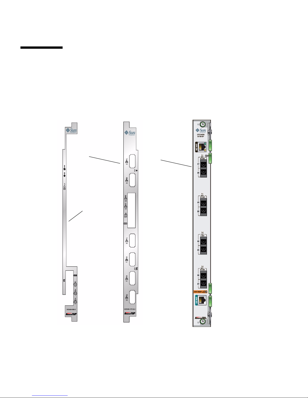
The following shows the Sun Netra CP3240 switch and the copper RTM
(XCP3240H-RTM-CU-Z) and the fiber optic RTM (XCP3240H-RTM-OP-Z).
FIGURE 1-1 Switch and RTM Faceplates
Copper RTM Fiber Optic
RTM
Switch
Faceplate
Page 31

Chapter 1 Getting Started 1-7
1.6.1 Base 10/100/1000 Uplink Ports (RJ-45)
There are two front panel Base 10/100/1000Base-T Ethernet uplink ports on the
faceplate. They are ports number 18 and 19 on the Base network.
1.6.2 10/100 Management Port (RJ-45)
There is a 10/100 management Ethernet port on the faceplate. This port can be used
to manage the Base and Fabric. This port and the 10/100 management port on the
RTM can be used at the same time.
1.6.3 Serial Management Port (RJ-45)
There is a RS-232 serial management port on the faceplate. This port can be used to
manage the Base and Fabric. See Section 4.4, “Serial Select” on page 4-8 for
information about how to switch between managing the Base and the Fabric.
1.7 RTM Airflows
1.7.1 RTM Airflow Requirements
The following chart provides the RTM airflow requirements. No alarms are triggered
at any of the listed temperatures for the given airflow.
TABLE 1-2 Airflow Requirements
Watts m3/min CFM
Power Level
25˚C 28˚C 40˚C 55˚C 25˚C 28˚C 40˚C 55˚C
25 0.07 0.07 0.14 0.14 2.5 2.5 5 5
Page 32
1-8 Sun Netra CP3240 Switch Installation Guide • September 2009
1.7.2 RTM Pressure Drop Versus Airflows (Impedence
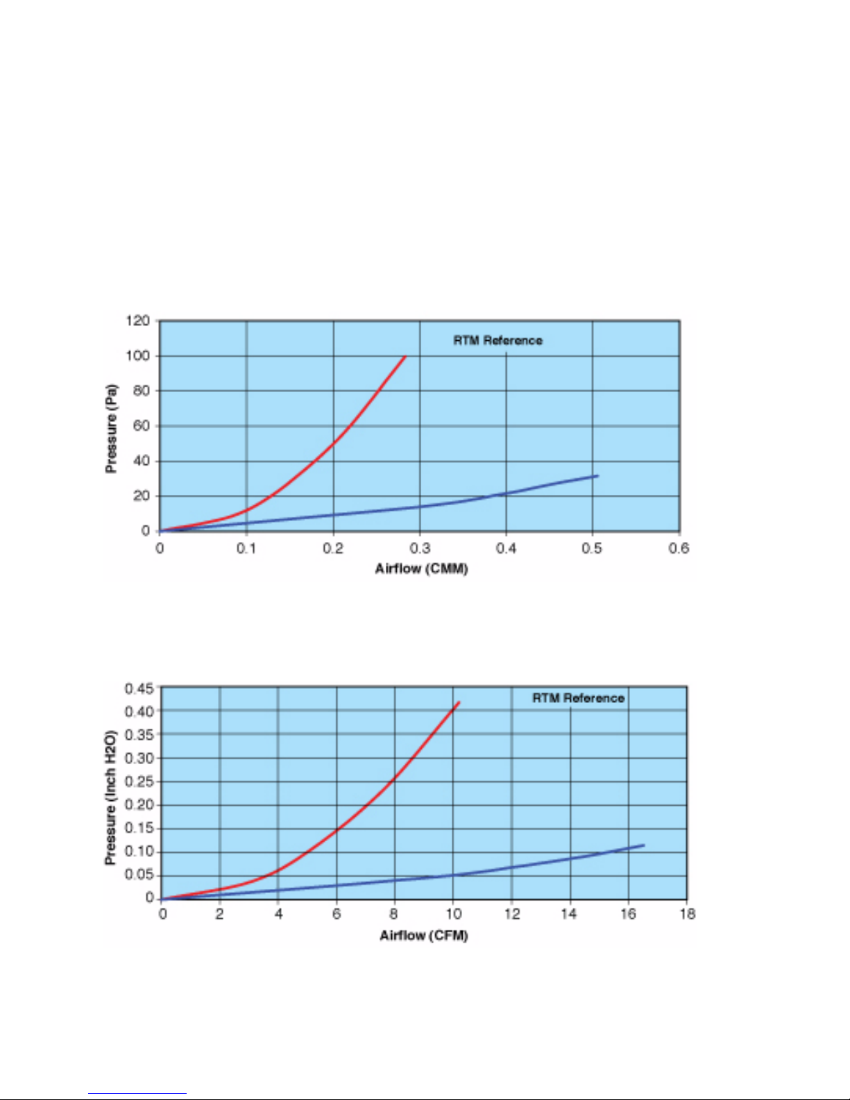
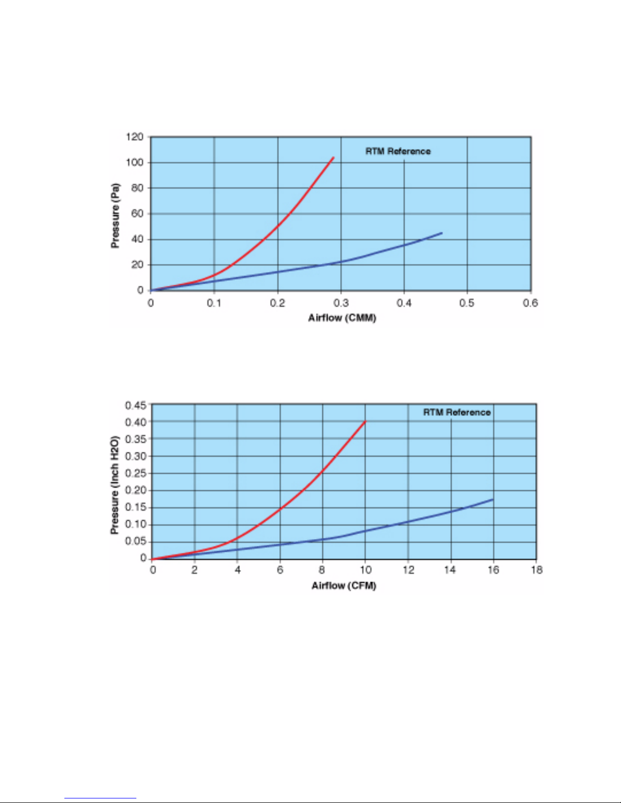
Curves)
The following graphs plot the impedance curves for the RTMs, per PICMG 3.0
requirements.
FIGURE 1-2 Netra CP3240H-RTM-CU Airflow (Pa)
FIGURE 1-3 Netra CP3240H-RTM-CU Airflow (InchesH
2
0)
Page 33
Chapter 1 Getting Started 1-9
FIGURE 1-4 Netra CP3240H-RTM-OP Airflow (Pa)
FIGURE 1-5 Netra CP3240H-RTM-OP Airflow (InchesH20)
Page 34

1-10 Sun Netra CP3240 Switch Installation Guide • September 2009
1.8 Removing and Installing Switches
This section describes how to remove and install switches.
If you are hot-swapping the rear transition module for a switch, you must remove
the switch from the front of the system before removing the rear transition module
from the rear of the system. Do not remove the rear transition module without first
removing the accompanying switch from the front.
1.8.1 Removing a Switch Set
Following are the instructions for removing a switch and, if necessary, the
accompanying rear transition module.
Page 35
Chapter 1 Getting Started 1-11
1.8.1.1 Removing a Switch From the Front of the Server
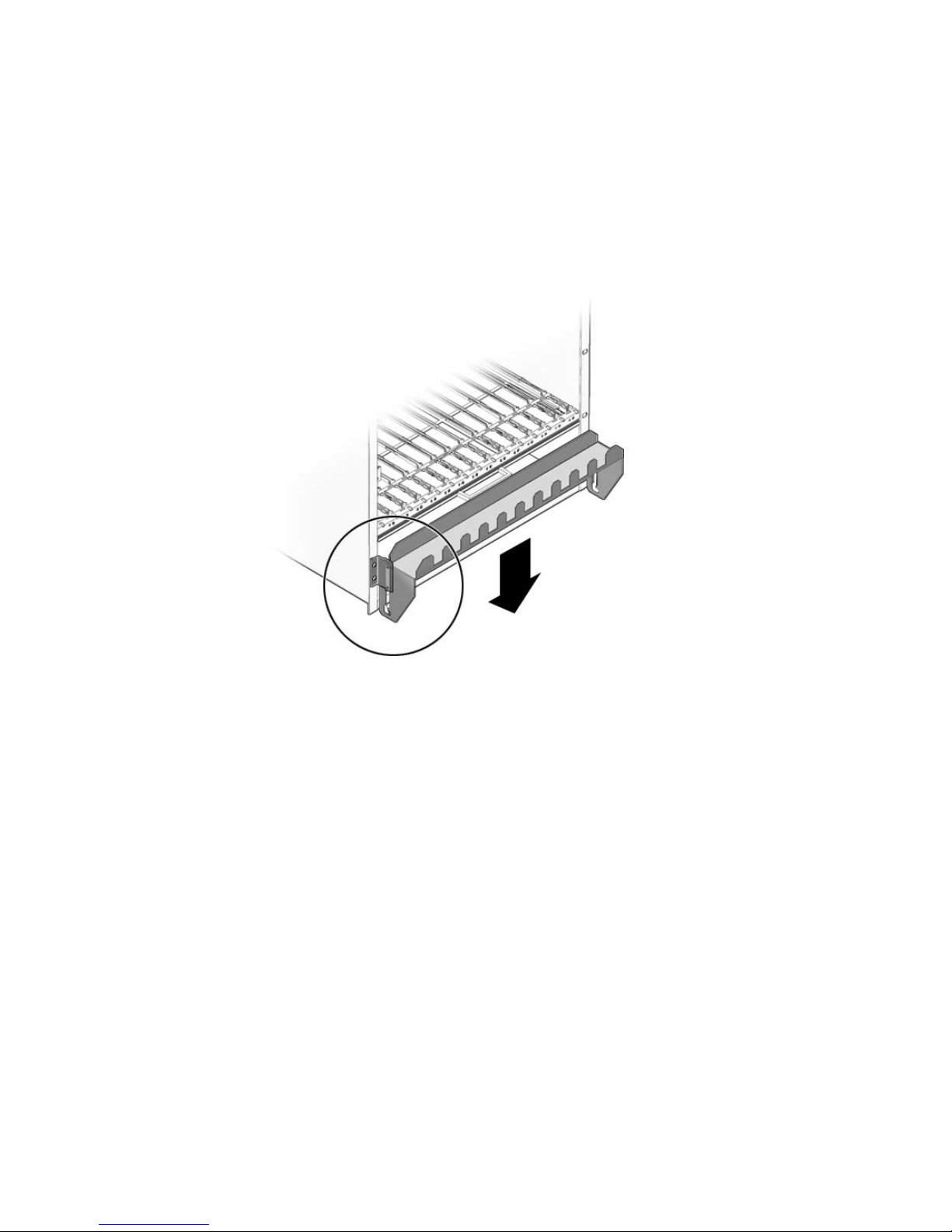
1. Move the front cable management bracket to the lower position (FIGURE 1-6).
FIGURE 1-6 Front Cable Management Bracket in Lower Position
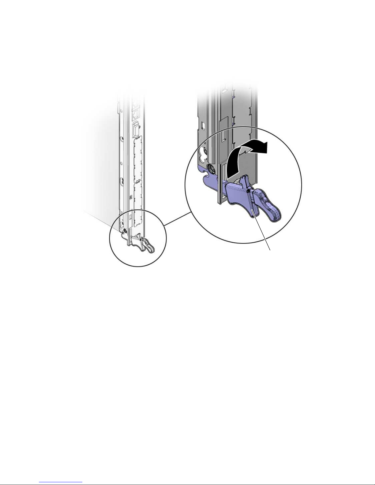
2. Disengage the injector/ejector mechanisms at the top and bottom of the board to
notify software that the board is about to be removed. Wait for the Hot-Swap LED
to light.
FIGURE 1-7 shows the proper way to remove or insert a hot-swappable board into a
system.
Page 36
1-12 Sun Netra CP3240 Switch Installation Guide • September 2009
FIGURE 1-7 Injector/Ejector on the Switch (Open Position)
3. Disconnect all cables connected to the switch.
4. Loosen the two board retention screws that fasten the board to the enclosure.
5. Open the ejectors fully, rotating the handles outward until the board disengages
from the midplane.
6. Slide the board evenly out of the enclosure.
7. Determine if you are going to replace the rear transition module.
■ If you are going to replace the rear transition module, go to “Removing a Rear
Transition Module for a Switch” on page 1-13.
■ If you are not going to replace the rear transition module, you must install a
replacement switch or a filler panel to maintain the enclosures shielding and
cooling performance. Refer to Section 1.8.2.2, “Installing a Switch” on page 1-14.
injector/ejector mechanism
Page 37

Chapter 1 Getting Started 1-13
Note – As long as the switch is removed from the slot, and the system is running
with only the single remaining switch, you do not have redundancy for that
component. Both switches must be installed and running to have redundancy for
that component.
1.8.1.2 Removing a Rear Transition Module for a Switch
1. Remove the switch from the front of the server, if you have not already done so.
Refer to “Removing a Switch From the Front of the Server” on page 1-11 for those
instructions. Do not remove the rear transition module until you have first removed
the switch.
Note – Opening the handle on the RTM shuts down both the RTM and the switch.
2. Disconnect any cables connected to the rear transition module for the switch.
3. Loosen any retention screws that fasten the module to the enclosure.
4. Open the ejectors fully, rotating the handles outward until the board disengages
from the midplane.
5. Slide the module evenly out of the enclosure.
6. Install a replacement rear transition module or a filler panel to maintain the
enclosure’s shielding and cooling performance.
Refer to Section 1.8.2.1, “Installing the Rear Transition Module for a Switch” on
page 1-14.
Caution – Failure to cover all rear panel slots with rear transition modules or filler
panels can negatively impact the cooling of the system.
Page 38

1-14 Sun Netra CP3240 Switch Installation Guide • September 2009
1.8.2 Installing a Switch Set
If you have a rear-access server, you must install the rear transition module before
installing the front switch.
■ If you want to install the rear transition module, go to Section 1.8.2.1, “Installing
the Rear Transition Module for a Switch” on page 1-14.
■ If you want to install a switch, go to Section 1.8.2.2, “Installing a Switch” on
page 1-14.
1.8.2.1 Installing the Rear Transition Module for a Switch
1. Choose an appropriate slot for the rear transition module.
Rear transition modules must be installed inline behind the accompanying front
board. For example, if the accompanying front board is installed in slot 7, its rear
transition module must be installed at the back of the system in slot 7.
2. Remove the filler panel, if necessary.
3. Prepare the rear transition module by opening its injector/ejector handles.
4. Carefully align the edges of the board with the guides in the slot.
Look into the enclosure to verify correct alignment of the rails in the guides.
Caution – Do not force the module into the slot. If it does not fit properly, check to
ensure that you have the correct matching RTM for the switch.
5. Keeping the board aligned in the guides, slide the board in until the
injector/ejector mechanisms engage the retention bar.
6. Simultaneously push in the board and rotate the injector/ejector handles to their
closed positions (rotate inward) to seat the midplane connectors.
7. Tighten the board retention screws to anchor the board in the shelf.
8. Connect the cables to the rear transition module.
1.8.2.2 Installing a Switch
1. Locate the switch slots.
The switches can be inserted only in slot 7 or slot 8 in the Netra CT 900 server.
2. Move the front cable management bracket to the lower position (
FIGURE 1-6).
3. Remove the filler panel, if necessary.
Page 39

Chapter 1 Getting Started 1-15
4. Prepare the switch by opening its injector/ejector handles (FIGURE 1-7).
5. Carefully align the edges of the board with the guides in the slot.
Look into the enclosure to verify correct alignment of the rails in the guides.
6. Keeping the board aligned in the guides, slide the board in until the
injector/ejector mechanisms engage the retention bar.
7. Simultaneously push in the board and rotate the injector/ejector handles to their
closed positions (rotate inward) to seat the midplane connectors.
If system power is on, the Hot-Swap LED should light up. The Hot-Swap LED
should blink for several seconds, and then go off. If the Hot-Swap LED does not go
off after several seconds, push harder on the injector/ejector handles to verify that
they are pushed in all the way.
8. Tighten the board retention screws to anchor the board in the shelf.
9. Connect the cables to the switch.
1.9 Switch LEDs
The following sections give the status information for all of the LEDs on the switch.
■ “ATCA Board Status LEDs” on page 1-15
■ “Hot-Swap LED” on page 1-16
1.9.1 ATCA Board Status LEDs
TABLE 1-3 describes the three LEDs defined by ATCA to monitor board status.
TABLE 1-3 ATCA Board Status LEDs
LED Color Normal Operation Description
OOS Red Off Out of service. This LED lights on a critical switch
error, such that the board should be removed.
OK Green On This LED is lit when the switch is booted and
switching
A Amber Off Minor Error/User Defined. This LED can be defined
by the user via software applicatons.
Page 40

1-16 Sun Netra CP3240 Switch Installation Guide • September 2009
Note that both the OOS and MINOR LEDs are lit when the board is powered but not
booted. This includes all Hot-Swap states M1 through M3. Refer to “Hot-Swap LED”
on page 1-16.
1.9.2 Hot-Swap LED
This blue LED communicates the Hot-Swap status of the switch. TABLE 1-4 shows the
different states of the Hot-Swap LED.
Note – A board should be hot-swapped only when the LED is solid blue.
TABLE 1-4 Hot-Swap LED States
Order Visible State State Description
1 Solid M1 FRU Inactive The Intelligent Platform
Management Interface (IPMI)
microcontroller is booted, but the
payload is not. The bottom latch is
not fully closed.
2 Blinking (from solid) M2 Activation
Request
The IPMI microcontroller has
requested permission to boot the
payload from the shelf
management controller.
3 Off M3-M4 Active The IPMI microcontroller has
received permission to boot the
payload, and has done so. This
should be the state under normal
operation.
4 Blinking (from off) M5-M6
Deactivation
Request
The IPMI microcontroller has
requested permission to shut
down the payload. Opening the
bottom latch activates this state.
Back to 1
Page 41

2-1
CHAPTER
2
Overview
This chapter introduces the key features of the switch and RTMs. This chapter
includes a product definition, a list of product features, and functional block
diagrams with brief descriptions. This chapter can be used to compare the features
of the switch against the needs of a specific application.
This chapter contains the following topics:
■ Section 2.1, “Features” on page 2-2
■ Section 2.2, “Switch Components” on page 2-6
■ Section 2.3, “Protocols, RFCs, and MIBs Support” on page 2-8
■ Section 2.4, “Functional Diagrams and Port Maps” on page 2-17
Page 42

2-2 Sun Netra CP3240 Switch Installation Guide • September 2009
2.1 Features
Part of Sun’s ATCA platform, the Sun Netra CP3240 switch complies with PICMG
3.0 R2.0 ECN002 and PCIMG 3.1 Option 1 and Option 9. The Sun Netra CP3240
switch implements two separate switched networks on a single PCB. By separating
the Base and Fabric networks, the Sun Netra CP3240 switch provides a separate
control plane and data plane. It provides 1Gigabyte Ethernet switching on the 3.0
Base Fabric, and the 3.1 Expansion Fabric provides 1Gigabyte/10Gigabyte Ethernet
switching. Both of these networks are fully managed with the robust FASTPATH
management suite. Both networks support Layer 2 switching as well as Layer 3
routing.
The Sun Netra CP3240 switch can host three AdvancedMC mid-size modules. A
variety of different AMC types can be used, including AMC.1, AMC.2, and AMC.3.
Netra CP3240 switch supports connectivity to three AMCs and to RTMs with
multiple 10Gigabyte-Ethernet links.
The XCP3240H-RTM-CU-Z (copper) and XCP3240H-RTM-OP-Z (fiber optic) are
Sun’s RTMs that are paired with the Sun Netra CP3240 switch.
The following sections briefly outline the features of the Sun Netra CP3240 switch.
2.1.1 General
■ PICMG 3.0 AdvancedTCA form factor
■ PICMG 3.0 R2.0 ECN002 compliant
■ PICMG 3.0 compliant 10/100/1000Base-T Ethernet Base Fabric hub board
■ PICMG 3.1 Option 1 (1000Base-BX) and Option 9 (10GBase-BX4) compliant
Ethernet Expansion Fabric hub board
■ Two separate subsystems providing two separate networks on a single PCB
■ 14-slot shelf supported
■ Manage both switches with a single serial port and Ethernet management port
■ Low power < 100 watts under heavy load (without AMCs)
■ Operates with or without an RTM
■ Changeable RTM to support different technologies (for example, RJ-45 versus SFP,
XFP versus CX4)
■ AdvancedTCA and AdvancedMC IPMI support with Pigeon Point Systems
BMR-H8S-AMCc Board Manager
■ Dual-image IPMI firmware
Page 43

Chapter 2 Overview 2-3
2.1.2 Base Interface
■ Broadcom BCM56503-based design
■ Full gigabit non-blocking, wire-speed switching/routing
■ Layer 2 switching
■ Layer 3 routing
■ 27 ports:
■ 14 10/100/1000Base-T Ethernet ports for node slots
■ 1 10/100/1000Base-T Ethernet port for redundant switch
■ 2 10/100/1000Base-T Ethernet ports for front panel access
■ 2 10/100/1000Base-T Ethernet ports for rear panel access (with RTM)
■ 3 1000Base-BX Ethernet ports for AMC sites (AMC.2 Type E1 compliant)
■ 1 10/100/1000Base-T Ethernet port primary shelf manager
■ 1 10/100Base-TX Ethernet port for redundant shelf manager (cross-connect)
■ 1 10GBase-BX4 Ethernet port to the redundant hub board via the Update
Channel
■ 2 10GBase-CX4 Ethernet ports for rear-panel access (with RTM)
■ 400MHz Freescale MPC8247 control CPU
■ 256MB PC100 SDRAM
■ 64MB on-board flash
■ Hardware redundant flash for guaranteed flash recovery
■ 10/100BaseTX out-of-band management Ethernet port
■ Front- and rear-access RJ-45 serial management port
■ Full IPv6 support
■ L2 and L3 Multicast support
Page 44

2-4 Sun Netra CP3240 Switch Installation Guide • September 2009
2.1.3 Fabric Gigabit Interface
■ Broadcom BCM56800-based design
■ Full gigabit non-blocking, wire-speed switching/routing
■ Layer 2 switching
■ Layer 3 routing
■ 20 total ports:
■ 14 10GBase-BX4 Ethernet ports for node slots
■ 1 10GBase-BX4 Ethernet port for redundant switch
■ 1 10GBase-BX4 for AMC site (AMC.2 Type 5)
■ 4 10GBase-CX4 for rear-panel access (with RTM)
■ Auto-negotiation between 1GbE (1000Base-BX 3.1 Option 1) and 10GbE
(10GbEBase-BX4 3.1 Option 9)
■ 400MHz Freescale MPC8247 control CPU
■ 256MB PC100 SDRAM
■ 64MB on board flash
■ Hardware redundant flash for guaranteed flash recovery
■ 10/100BaseTX out-of-band RJ-45 management Ethernet port
■ Front- and rear-access RJ-45 serial management port
■ Full IPv6 support
■ L2 and L3 multicast support
Page 45

Chapter 2 Overview 2-5
2.1.4 AMC Sites
■ Site 1 1000Base-BX to 3.0 network (AMC port 0) is ethernet port 22
■ Site 2 1000Base-BX to 3.0 network (AMC port 0) is ethernet port 23
■ Site 2 10GBase-BX to 3.1 network (AMC port 8-11) is ethernet port 16
■ Site 3 1000Base-BX to 3.0 network (AMC port 0) is ethernet port 24
Site 1: AMC.0 Mid-size, AMC.2 Type E1
■ 1000Base-BX to 3.0 network (AMC port 0)
■ AMC ports 4-7 connected to AMC site 2
■ SAS/SATA ports routed between AMCs (AMC port 2-3)
Site 2: AMC.0 Mid-size, AMC.2 Type 5 and E1
■ 10GBase-BX4 to 3.1 network (AMC port 8-11)
■ 1000Base-BX to 3.0 network (AMC port 0)
■ AMC ports 4-7 connected to AMC site 1
■ SAS/SATA ports routed between AMCs (AMC port 2-3)
Site 3: AMC.0 Mid-size, AMC.2 Type E1
■ 1 1000Base-BX to 3.0 network (AMC port 0)
■ SAS/SATA ports routed between AMCs (AMC port 2-3)
■ Update channel support for redundant master clock generators (AMC port 15)
■ PCI-E Fabric clock support
Page 46

2-6 Sun Netra CP3240 Switch Installation Guide • September 2009
2.2 Switch Components
The following sections list and describe key components of the Sun Netra CP3240
switch.
2.2.1 Broadcom StrataXGS 3 BCM56503 Ethernet Switch
The Sun Netra CP3240 switch uses Broadcom StrataXGS 3 BCM56503 for Base
Ethernet switching/routing. This chip is an Ethernet switch with 24 1Gigabyte ports
and 3 10Gigabyte ports. It provides non-blocking, wire-speed switching and routing
on all ports under 100% load. The BCM56503 features many advanced features
presented to the user via the FASTPATH software. See the Section 4.10, “FASTPATH”
on page 4-18 for more information.
2.2.2 Broadcom StrataXGS 3 BCM56800 Ethernet Switch
The Sun Netra CP3240 switch uses Broadcom StrataXGS 3 BCM56800 for Fabric
Ethernet switching/routing. This chip is an Ethernet switch with 20 10Gigabyte
ports. It provides non-blocking, wire-speed switching and routing on all ports under
100% load. The BCM56800 features many advanced features presented to the user
via the FASTPATH software. See Section 4.10, “FASTPATH” on page 4-18 for more
information.
2.2.3 Broadcom BCM5464R and BCM5461S
10/100/1000Base-T Ethernet PHY
Quad and single ports respectively, the Broadcom PHYs provide the physical
interfacing for 10/100/1000Base-T. They are low-power devices and provide features
such as jumbo frames support, auto-MDIX, and cable testing.
Page 47

Chapter 2 Overview 2-7
2.2.4 Freescale PowerQUICC II MPC8247
Communications Processor
The Freescale MPC8247 is a microprocessor designed for maximum flexibility. It
features a dual core architecture with a PPC G2 LE core and a RISC core controlling
the peripherals. Running at 400MHz with only 1 watt of power, the MPC8247
provides high performance with incredibly low power consumption. Paired with the
256MB PC100 SDRAM and 64MB flash, the CPU subsystem of the Sun Netra CP3240
switch is more than enough to handle the switching application and future
upgrades.
2.2.5 Pigeon Point BMR-H8S-AMCc AdvancedTCA
IPMI Subsystem
The Sun Netra CP3240 switch uses the near-industry standard Pigeon Point Systems
BMR-H8S-AMCc for dedicated IPMI management. It controls all interaction between
the Sun Netra CP3240 switch and the shelf management controller. It fully supports
the PICMG 3.0 R2.0 ECN002 and the AMC.0 R2.0 specifications. The
BMC-H8S-AMCc provides all required management for the AMC modules, in
addition to the voltage monitoring, temperature monitoring, e-Keying, and other
services it provides for the Sun Netra CP3240 switch. Pigeon Point Systems is the
leading provider of IPMI firmware for AdvancedTCA, and the firmware has been
thoroughly tested to be fully compliant with the specification.
Page 48

2-8 Sun Netra CP3240 Switch Installation Guide • September 2009
2.3 Protocols, RFCs, and MIBs Support
The Sun Netra CP3240 switch features Level7 FastPath 2340 switching software,
version 4.4.4 and newer. This software provides layer 2 switching, quality of service,
IPv4 routing, IPv6 routing, and IP multicast.
2.3.1 FASTPATH Switching
■ IEEE 802.1ab—Link Level Discovery
■ IEEE 802.1D—Spanning Tree
■ IEEE 802.1p—Ethernet Priority with User Provisioning and Mapping
■ IEEE 802.1Q—Virtual LANs with Port-based VLANs
■ IEEE 802.1S—Multiple Spanning Tree
■ IEEE 802.1v—Protocol-based VLANs
■ IEEE 802.1W—Rapid Spanning Tree
■ IEEE 802.1X—Port-based Authentication
■ IEEE 802.3—10 Base-T
■ IEEE 802.3ab—1000 Base-T
■ IEEE 802.3ac—VLAN Tagging
■ IEEE 802.3ad—Link Aggregation
■ IEEE 802.3ae—10 Gigabyte
■ IEEE 802.3u—100 Base-T
■ GARP—Generic Attribute Registration Protocol: Clause 12, 802.1D-2004
■ GMRP—Dynamic L2 Multicast Registration: Clause 10, 802.1D-2004
■ GVRP—Dynamic VLAN Registration: Clause 11.2, 802.1Q-2003
■ IEEE 802.3x—Flow Control
■ draft-ietf-magma-snoop-10.txt—Considerations for IGMP and MLD Snooping
Switches
Page 49

Chapter 2 Overview 2-9
2.3.1.1 Additional Layer 2 Functionality
■ Broadcast/Multicast/Unknown Unicast storm recovery
■ Double VLAN/vMAN tagging
■ DHCP filtering
■ Jumbo Ethernet frames
■ Many-to-one port mirroring (Tx, Rx, both)
■ Static MAC filtering
■ MAC-based VLANs
■ IP subnet-based VLANs
■ Port description
■ Protected ports
■ Network and host DoS attack suppression
2.3.1.2 System Facilities
■ Event and Error Logging Facility
■ Run-time and configuration download capability
■ PING utility
■ XMODEM
■ RFC 768—UDP
■ RFC 783—TFTP
■ RFC 791—IP
■ RFC 792—ICMP
■ RFC 793—TCP
■ RFC 951—BootP
■ RFC 1321—Message Digest Algorithm
■ RFC 1534—Interoperation between BootP and DHCP
■ RFC 2030—Simple Network Time Protocol (SNTP) V4 for IPv4, IPv6, and OSI
■ RFC 2131—DHCP client/server
■ RFC 2132—DHCP options and BootP vendor extensions
■ RFC 2865—RADIUS client
■ RFC 2866—RADIUS accounting
■ RFC 2868—RADIUS attributes for Tunnel protocol support
■ RFC 2869—RADIUS extensions
■ rfc2869bis—RADIUS support for Extensible Authentication Protocol (EAP)
Page 50

2-10 Sun Netra CP3240 Switch Installation Guide • September 2009
■ RFC 3164—BSD Syslog protocol
■ RFC 3396—Encoding long options in the Dynamic Host Configuration Protocol
(DHCPv4)
■ RFC 3580—802.1X RADIUS usage guidelines
2.3.1.3 Switching MIBs
■ RFC 1213 — MIB-II
■ RFC 1493 — Bridge MIB
■ RFC 1643 — Ethernet-like MIB
■ RFC 2233 — The Interfaces Group MIB using SMI v2
■ RFC 2618 — RADIUS authentication client MIB
■ RFC 2620 — RADIUS accounting MIB
■ RFC 2674 — VLAN MIB
■ RFC 2737—Entity MIB version 2
■ RFC 2819—RMON groups 1, 2, 3 and 9
■ RFC 3291—Textual conventions for Internet Network Addresses
■ RFC 3635—Definitions of managed objects for the Ethernet-like interface types
■ IEEE 802.1X MIB (IEEE802.1-PAE-MIB)
■ IEEE 802.3AD MIB (IEEE802.3-AD-MIB)
■ FASTPATH Enterprise MIBs supporting switching features
2.3.1.4 Routing MIBs
■ RFC 1724—RIP v2 MIB extension
■ RFC 1850—OSPF MIB
■ RFC 2096—IP forwarding table MIB
■ RFC 2787—VRRP MIB
■ RFC 2863—The Interfaces Group MIB
■ FASTPATH Enterprise MIBs supporting routing features
Page 51

Chapter 2 Overview 2-11
2.3.2 FASTPATH Routing
■ RFC 826—Ethernet ARP
■ RFC 894—Transmission of IP Datagrams over Ethernet networks
■ RFC 896—Congestion control in IP/TCP networks
■ RFC 919—IP Broadcast
■ RFC 922—IP Broadcast in the presence of subnets
■ RFC 950—IP subnetting
■ RFC 1027—Using ARP to implement Transparent Subnet Gateways (proxy ARP)
■ RFC 1058—RIP v1
■ RFC 1256—ICMP router discovery messages
■ RFC 1321—Message Digest Algorithm
■ RFC 1765—OSPF database overflow
■ RFC 1812—Requirements for IP version 4 routers
■ RFC 2082—RIP-2 MD5 authentication
■ RFC 2131—DHCP relay
■ RFC 2328—OSPFv2 (FASTPATH supports Broadcast interfaces.)
■ RFC 2453—RIP v2
■ RFC 3046—DHCP/BootP relay
■ RFC 3101—OSPF “Not So Stubby Area” (NSSA) option
■ RFC 3768—Virtual Router Redundancy Protocol
■ Route redistribution across RIP and OSPF
■ VLAN routing
■ Weighted static routes
Page 52

2-12 Sun Netra CP3240 Switch Installation Guide • September 2009
2.3.3 FASTPATH Quality of Service
2.3.3.1 DiffServ
■ RFC 2474—Definition of the Differentiated Services field (DS field) in the IPv4
and IPv6 headers
■ RFC 2475—Architecture for differentiated services
■ RFC 2597—Assured Forwarding PHB Group
■ RFC 3246—Expedited forwarding PHB (Per-Hop Behavior)
■ RFC 3260—New terminology and clarifications for DiffServ
Optional policy attributes:
■ Assign matching traffic flow to a specific queue
■ Redirect or mirror (flow-based mirroring) matching traffic flow to a specific port
2.3.3.2 Access Control Lists (ACLs)
Permit/Deny actions for inbound or outbound IP traffic classification based on:
■ Type of Service (TOS) or Differentiated Services (DS) DSCP field
■ Source IP address
■ Destination IP address
■ TCP/UDP source port
■ TCP/UDP destination port
■ IP protocol number
Permit/Deny actions for inbound or outbound Layer 2 traffic classification based on:
■ Source MAC address
■ Destination MAC address
■ Ethertype
■ 802.1p user priority (outer and/or inner VLAN tag)
■ VLAN identifier value or range (outer and/or inner VLAN tag)
Optional rule attributes:
■ Assign matching traffic flow to a specific queue
■ Redirect or mirror (flow-based mirroring) matching traffic flow to a specific port
■ Generate trap log entries (ACL logging) containing rule hit counts
Page 53

Chapter 2 Overview 2-13
2.3.3.3 Class of Service (CoS)
Direct user configuration of the following:
■ IP DSCP to traffic-class mapping
■ Interface trust mode: 802.1p, IP DSCP, or untrusted
■ Interface traffic-shaping rate
■ Minimum and maximum bandwidth per queue
■ Strict priority versus weighted (WRR/WFQ) scheduling per queue
■ Tail drop versus weighted random early detection (WRED) queue depth
management
2.3.3.4 Quality of Service MIBs
■ RFC 3289—MIB for the Differentiated Services Architecture (read-only)
■ Private MIBs for full configuration of DiffServ, ACL, and CoS functionality
2.3.4 FASTPATH Multicast
■ RFC 1112—Host Extensions for IP multicasting
■ RFC 2236—IGMPv2
■ RFC 2362—PIM-SM
■ RFC 2365—Administratively scoped boundaries
■ RFC 3376—IGMPv3
■ IP multicast traceroute
■ Draft-ietf-pim-v2-dm-03—PIM-DM
■ Draft-ietf-idmr-dvmrp-v3-10—DVMRP
■ Static RP configuration
■ Draft-holbrook-idmr-igmpv3-ssm-08.txt—IGMPv3/MLDv2 for SSM
■ Draft ietf-magma-igmp-proxy-06.txt—IGMP/MLD-based multicast forwarding
(IGMP/MLD Pproxying)
■ Draft ietf-smm-arch-06.txt—Source specific multicast for IP
■ Draft ietf-magma-igmpv3-and-routing-05.txt—IGMPv3 and Multicast Routing
Protocol interaction
Page 54

2-14 Sun Netra CP3240 Switch Installation Guide • September 2009
2.3.4.1 Multicast MIBs
■ RFC 2932—IPv4 multicast routing MIB
■ RFC 2933—IGMP MIB
■ RFC 2934—PIM MIB for IPv4
■ Draft-ietf-magma-mgmd-mib-03.txt—Multicast Group Membership Discovery
MIB
■ Draft-ietf-idmr-dvmrp-mib-11.txt—DVMRP MIB
■ IANA-RTP-PROTO-MIB
■ FASTPATH Enterprise MIBs supporting multicast features
2.3.5 FASTPATH IPv6 Routing
■ RFC 1981—Path MTU for IPv6
■ RFC 2373—IPv6 addressing
■ RFC 2460—IPv6 protocol specification
■ RFC 2461—Neighbor discovery
■ RFC 2462—Stateless autoconfiguration
■ RFC 2463—ICMPv6
■ RFC 2464—IPv6 over Ethernet
■ RFC 2711—IPv6 router alert
■ RFC 2740—OSPFv3 (FASTPATH supports Broadcast and Point-to-Point
interfaces.)
■ RFC 2893—Transition mechanisms for IPv6 hosts and routers (6over4 configured)
■ RFC 3315—DHCPv6 (stateless + relay)
■ RFC 3484—Default address selection for IPv6
■ RFC 3493—Basic Socket Interface for IPv6
■ RFC 3513—Addressing architecture for IPv6
■ RFC 3542—Advanced Sockets API for IPv6
■ RFC 3587—IPv6 Global Unicast Address format
■ RFC 3736—Stateless DHCPv6
■ Dual IPv4/IPv6 TCP/IP stack
Page 55

Chapter 2 Overview 2-15
2.3.5.1 IPv6 Routing MIBs
■ RFC 2465—IPv6 MIB
■ RFC 2466—ICMPv6 MIB
■ FASTPATH Enterprise MIBs supporting IPv6 features
2.3.6 FASTPATH Management
■ RFC 854—Telnet
■ RFC 855—Telnet option specifications
■ RFC 1155—SMI v1
■ RFC 1157—SNMP
■ RFC 1212—Concise MIB definitions
■ RFC 1867—HTML/2.0 forms with file upload extensions
■ RFC 1901—Community based SNMP v2
■ RFC 1908—Coexistence between SNMP v1 and SNMP v2
■ RFC 2068—HTTP/1.1 protocol as updated by draft-ietf-http-v11-spec-rev-03
■ RFC 2271—SNMP framework MIB
■ RFC 2295—Transparent content negotiation
■ RFC 2296—Remote variant selection; RSVA/1.0 state management cookies
draft-ietf-http-state-mgmt-05
■ RFC 2570—Introduction to SNMPv3
■ RFC 2576—Coexistence between SNMP v1, v2 and v3
■ RFC 2578—SMI v2
■ RFC 2579—Textual conventions for SMI v2
■ RFC 2580—Conformance statements for SMI v2
■ RFC 3410—Introduction and applicability statements for Internet-Standard
Management Framework
■ RFC 3411—Architecture for describing SNMP management frameworks
■ RFC 3412—Message processing and dispatching for SNMP
■ RFC 3413—SNMP applications
■ RFC 3414—User-based security model for SNMP v3
■ RFC 3415—View-based access control model for SNMP
■ RFC 3416—Version 2 of the protocol operations for SNMP
Page 56

2-16 Sun Netra CP3240 Switch Installation Guide • September 2009
■ RFC 3417—Transport mappings for SNMP
■ RFC 3418—MIB for SNMP
■ Configurable management VLAN
2.3.6.1 SSL 3.0 and TLS 1.0
■ RFC 2246—TLS protocol, version 1.0
■ RFC 2346—AES Ciphersuites for transport layer security
■ RFC 2818—HTTP over TLS
2.3.6.2 SSH 1.5 and 2.0
■ Draft-ietf-secsh-transport-16—SSH Transport Layer Protocol
■ Draft-ietf-secsh-userauth-17—SSH Authentication Protocol
■ Draft-ietf-secsh-connect-17—SSH Connection Protocol
■ Draft-ietf-secsh-architecture-14—SSH protocol architecture
■ Draft-ietf-secsh-publickeyfile-03—SECSH Public Key File format
■ Draft-ietf-secsh-dh-group-exchange-04—Diffie-Hellman Group Exchange for the
SSH Transport Layer Protocol
■ HTML 4.0 Specification—December, 1997
■ Java and Java Script 1.3
2.3.6.3 Additional Management Features
■ Industry Standard CLI with the following features:
■ Scripting capability
■ Command completion
■ Context sensitive help
■ User password encryption
■ Multi-session Telnet server
■ TACACS+
■ Dual firmware image support
Page 57
Chapter 2 Overview 2-17
2.4 Functional Diagrams and Port Maps
2.4.1 Switch
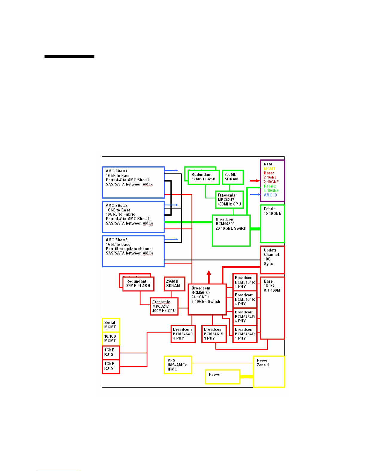
FIGURE 2-1 Switch Functional Block Diagram
Page 58

2-18 Sun Netra CP3240 Switch Installation Guide • September 2009
2.4.2 Rear Transition Modules (RTM)s
The Sun Netra CP3240 switch supports RTMs through ATCA Zone 3 connectors (see
TABLE 2-2). The Sun Netra CP3240 switch was designed to support multiple RTM
designs.
4 Fabric 10Gigabyte, 2 Base 10Gigabyte, 2 Base 1Gigabyte, AMC I/O, and
management ports are run to the RTM. Several voltage rails are supplied, and all of
the signals needed to design an ECN002 compliant RTM are present.
The Sun Netra CP3240 switch is paired with either a copper or fiber optic RTM. The
following sections describe each RTM.
TABLE 2-1 Switch External Ports
Front Panel Port Type Fiber Optic AMC Module Logical Port Comments
RJ-45 #1 Serial RS-232 RS-232 RJ-45
RJ-45 #2 Management 10/100 Base T RJ-45
RJ-45 #3 Base 1GBE 10/100/1000Base T RJ-45 Base - 18 Standard I/F is copper
RJ-45 #4 Base 1GBE 10/100/1000Base T RJ-45 Base - 19 Standard I/F is copper
TABLE 2-2 Zone 3 RTM Ports
Base Ports 1G Infrastructure 10G Infrastructure
Base Port 20 1G SGMII None
Base Port 21 1G SGMII None
Base Port 26 None 10G XAUI
Base Port 27 None 10G XAUI
Fabirc Port 17 1G SGMII 10G XAUI
Fabirc Port 18 1G SGMII 10G XAUI
Fabirc Port 19 1G SGMII 10G XAUI
Fabirc Port 20 1G SGMII 10G XAUI
Page 59
Chapter 2 Overview 2-19
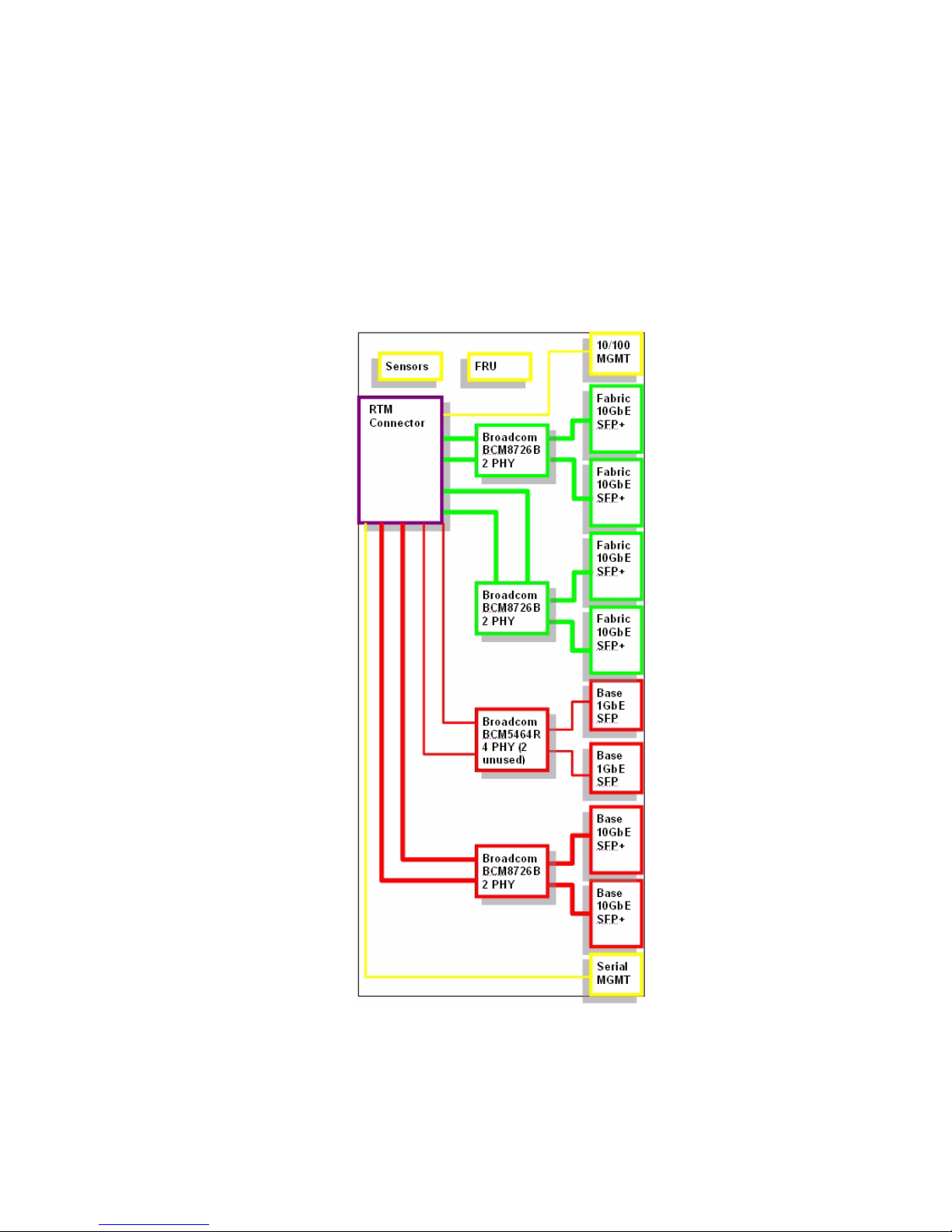
2.4.2.1 Copper RTM
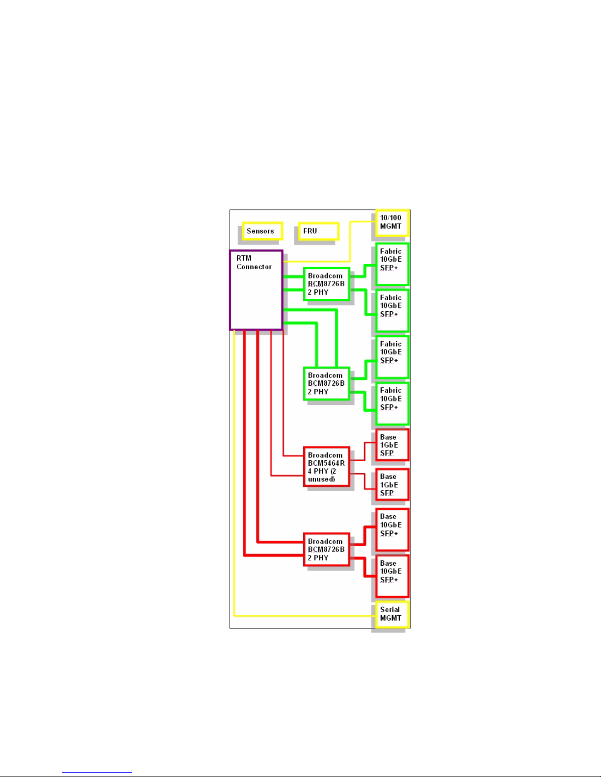
The XCP3240H-RTM-CU-Z is the Sun Netra CP3240 switch’s copper RTM pairing.
This RTM supports all the ports the Sun Netra CP3240 switch provides using
10GBase-CX4 for the 10Gigabyte and 10/100/1000Base-T for the 1Gigabyte ports.
FIGURE 2-2 Copper RTM Functional Block Diagram
Page 60

2-20 Sun Netra CP3240 Switch Installation Guide • September 2009
TABLE 2-3 Copper RTM External Ports
Port Type RTM Module Logical Port Comments
Base 10GBE XAUI CX4 Base - 27
Base 10GBE XAUI CX4 Base - 26
Base 1GBE 10/100/1000Base T RJ-45 Base - 20 Standard I/F is copper
Base 1GBE 10/100/1000Base T RJ-45 Base - 21 Standard I/F is copper
Management 10/100 Base T RJ-45
Serial RS-232 RS-232 RJ-45
Fabric 10GBE XAUI CX4 Fabric - 17
Fabric 10GBE XAUI CX4 Fabric - 18
Fabric 10GBE XAUI CX4 Fabric - 19
Fabric 10GBE XAUI CX4 Fabric - 20
TABLE 2-4 Copper RTM Port Restrictions
Port 1G Infrastructure 1G Port 10G Infrastructure 10G Port
Base Port 20 SERDES 1000Base-T RJ45 None None
Base Port 21 SERDES 1000Base-T RJ45 None None
Base Port 26 None None XAUI 10GBase-CX4
Base Port 27 None None XAUI 10GBase-CX4
Fabirc Port 17 None None XAUI 10GBase-CX4
Fabirc Port 18 None None XAUI 10GBase-CX4
Fabirc Port 19 None None XAUI 10GBase-CX4
Fabirc Port 19 None None XAUI 10GBase-CX4
Fabirc Port 20 None None XAUI 10GBase-CX4
Page 61
Chapter 2 Overview 2-21
2.4.2.2 Fiber Optic RTM
The XCP3240H-RTM-OP-Z is the Sun Netra CP3240 switch’s fiber optic RTM pairing.
This RTM supports all the ports the Netra CP3240 switch provides using 10GBase-X
for the 10Gigabyte and 1000Base-X for the 1Gigabyte ports.
FIGURE 2-3 Fiber Optic RTM Functional Block Diagram
Page 62

2-22 Sun Netra CP3240 Switch Installation Guide • September 2009
Note – For enabling 1G operation of Fabric ports 17-20, see Section 4.12, “Fiber
Optic RTM Configuration” on page 4-25.
TABLE 2-5 Fiber Optic External RTM Ports
Port Type Fiber Optic RTM Module Logical Port Comments
Management 10/100 Base T RJ-45 Not a module, 10/100Base T
Base 10GBE 10GBase-X SFP+ Base - 27 Cannot Support 1G Operation
Base 10GBE 10GBase-X SFP+ Base - 26 Cannot Support 1G Operation
Base 1GBE 1000Base-X SFP Base - 20 Can Support 1G SFP Copper
Base 1GBE 1000Base-X SFP Base - 21 Can Support 1G SFP Copper
Serial RS-232 10GBase-X SFP+ Fabric - 17 Can Support 1G SFP Copper
Fabric 10GBE 10GBase-X SFP+ Fabric - 18 Can Support 1G SFP Copper
Fabric 10GBE 10GBase-X SFP+ Fabric - 19 Can Support 1G SFP Copper
Fabric 10GBE 10GBase-X SFP+ Fabric - 20 Can Support 1G SFP Copper
Serial RS-232 Serial RS232 RJ-45 Not a module, RS232 Serial
TABLE 2-6 Fiber Optic RTM Port Restrictions
Port 1G Infrastructure 1G Port 10G Infrastructure 10G Port
Base Port 20 SERDES SFP LX SX None None
Base Port 21 SERDES SFP LX SX None None
Base Port 26 None None XAUI SFP+ LX SX LRM
Base Port 27 None None XAUI SFP+ LX SX LRM
Fabric Port 17 SERDES SFP LX SX XAUI SFP+ LX SX LRM
Fabric Port 18 SERDES SFP LX SX XAUI SFP+ LX SX LRM
Fabric Port 19 SERDES SFP LX SX XAUI SFP+ LX SX LRM
Fabric Port 20 SERDES SFP LX SX XAUI SFP+ LX SX LRM
Page 63
Chapter 2 Overview 2-23
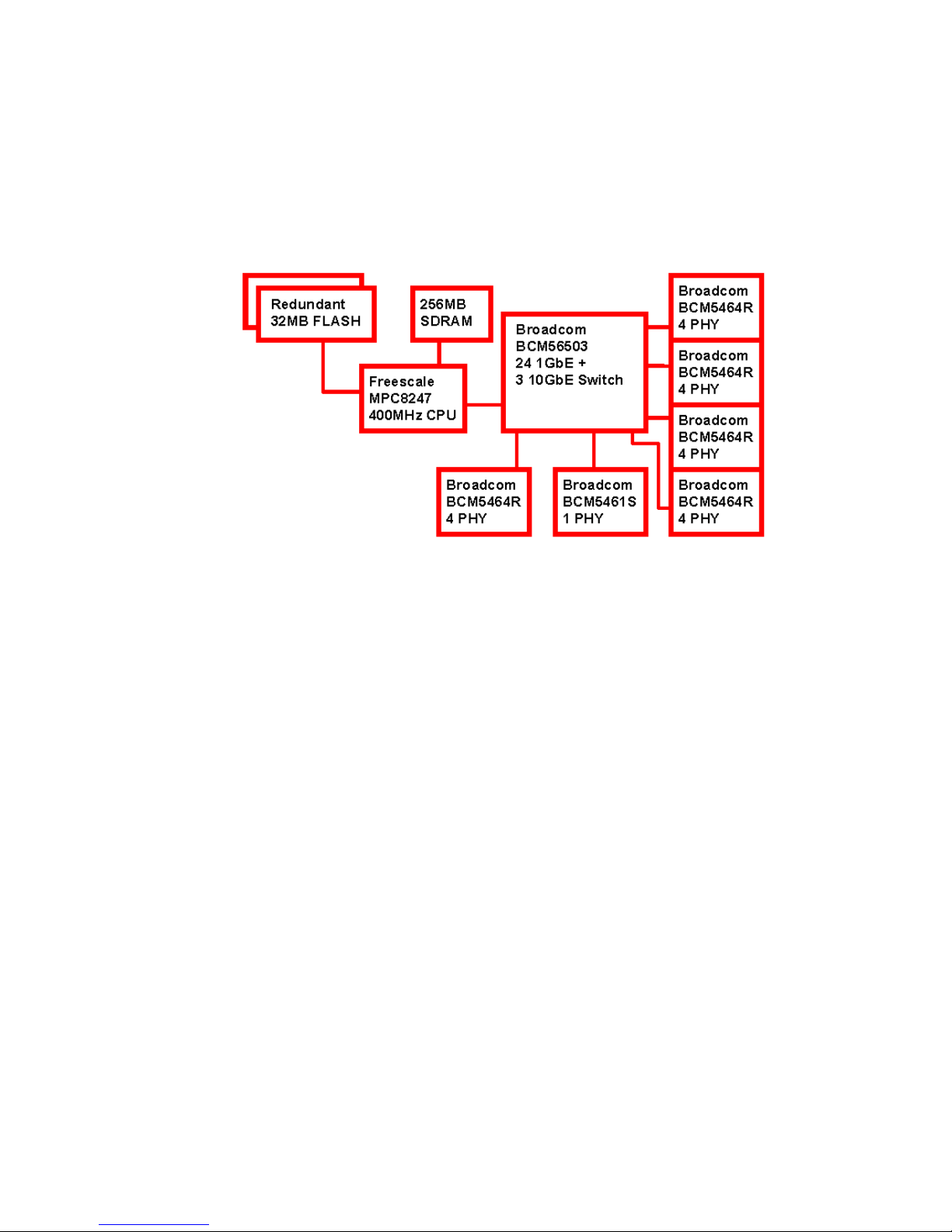
2.4.3 Base Fabric Switch Subsystem
FIGURE 2-4 Base Fabric Switch Subsystem
PICMG 3.0 AdvancedTCA defines 10/100/1000Base-T Ethernet over the Base Fabric,
called “Base” in this guide. The Base is designed to be the control plane for the shelf.
Scaling from 10Mbps to 1000Mbps, the Base interface can accommodate a wide
variety of node boards. The Base interface on the Sun Netra CP3240 switch is based
around three main components: the Broadcom BCM56503, the Broadcom BCM5464x,
and the Freescale MPC8247.
Page 64
2-24 Sun Netra CP3240 Switch Installation Guide • September 2009
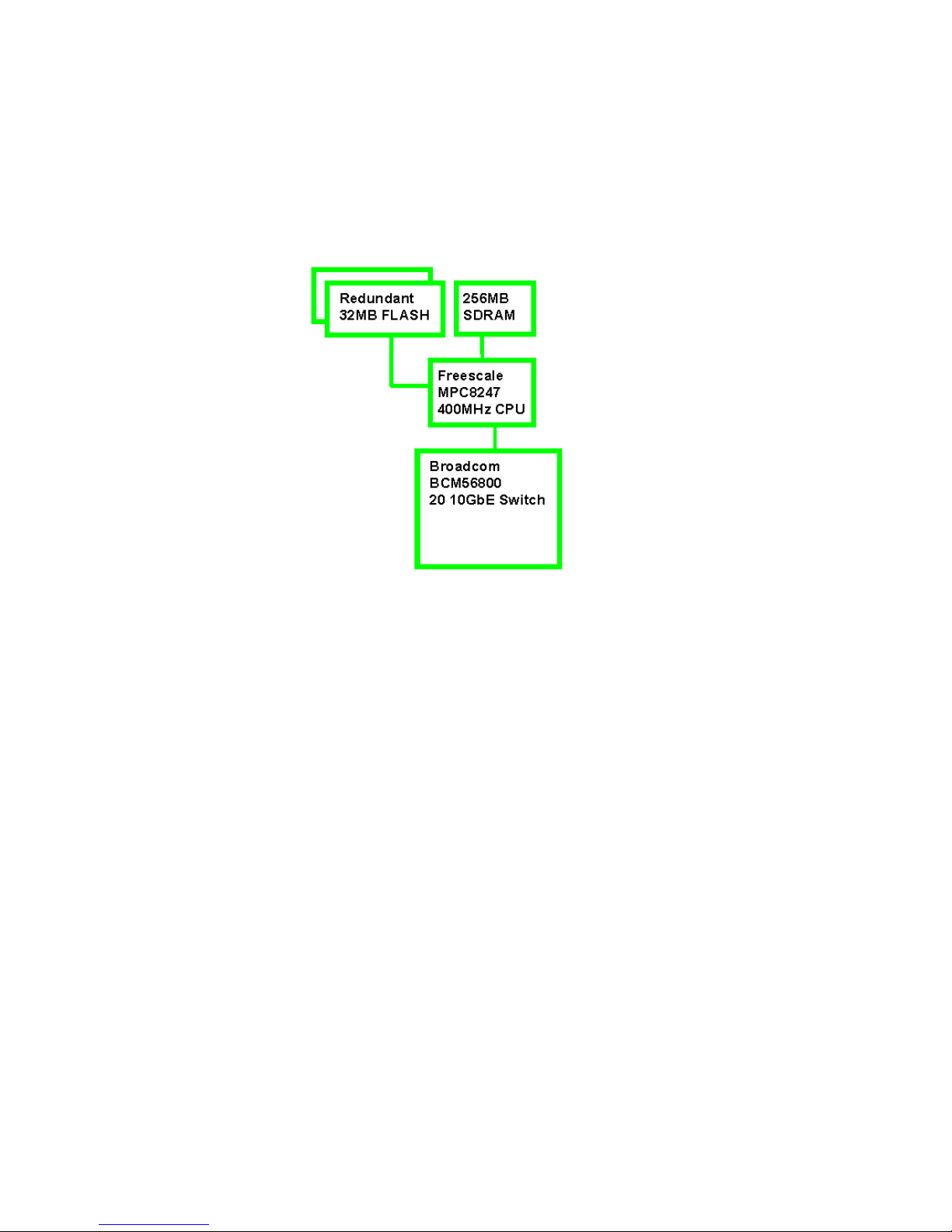
2.4.4 Expansion Fabric Switch Subsystem
FIGURE 2-5 Expansion Fabric Switch Subsystem
PICMG 3.0 AdvancedTCA provides an agnostic mesh on the backplane called the
Expansion Fabric. This interface is the data plane in the shelf. The Expansion Fabric
is called “Fabric” in this guide. This fabric can be several different technologies
defined by AdvancedTCA sub-specifications. The Sun Netra CP3240 switch is
designed to comply with PICMG 3.1 Ethernet/Fibre Channel for AdvancedTCA Systems,
options 1 and option 9. That means the Sun Netra CP3240 switch provides a single
1/10Gigabyte port to each node board.
The Fabric uses 10GBase-BX4 Ethernet to provide connectivity between boards
though the backplane. The Fabric can scale down to 1Gigabyte and work with
1000Base-BX boards. The Fabric subsystem is based around two main components:
the Broadcom BCM56800 and the Freescale MPC8247.
Page 65

Chapter 2 Overview 2-25
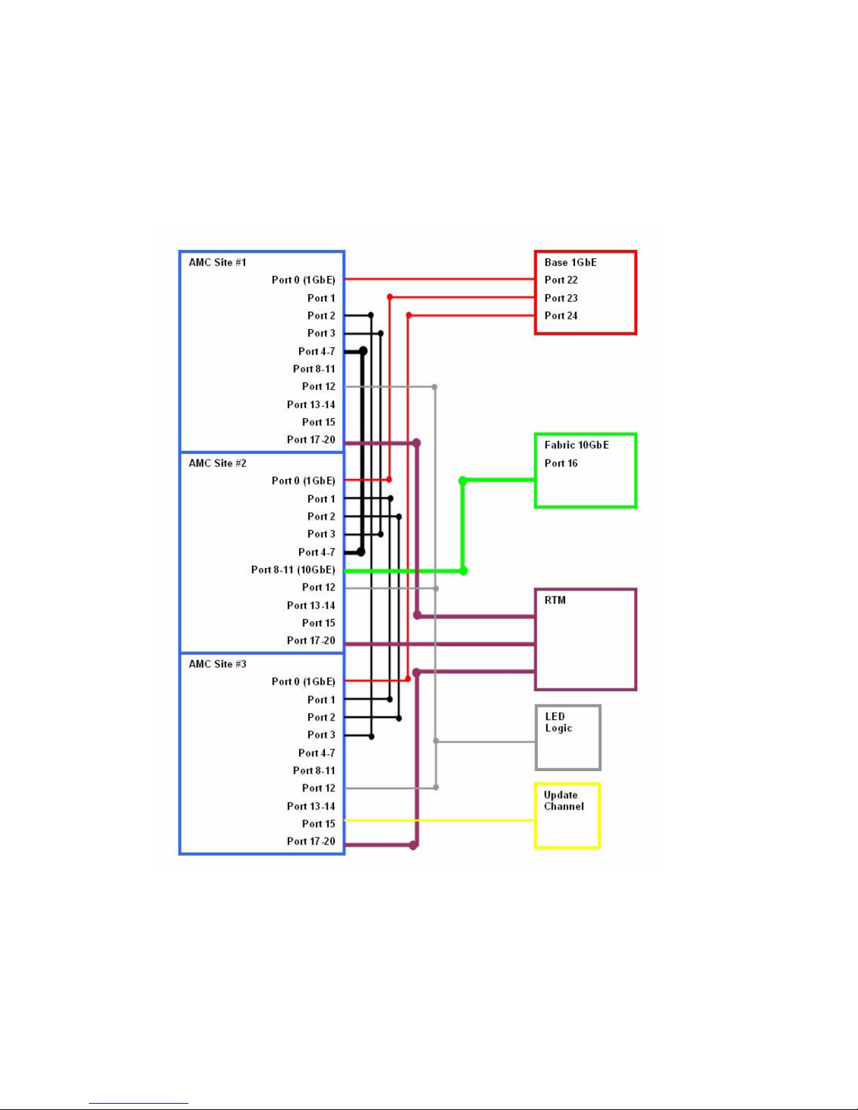
2.4.5 AdvancedMC Sites
PICMG AdvancedMC AMC.0 defines hot-swappable daughter cards to be used in
PICMG architectures. The Sun Netra CP3240 switch supports three AMC sites so
that the functionality of the Sun Netra CP3240 switch can be expanded. AMC.2
(Ethernet) AMCs are supported with direct connections to the Base and Fabric
subsystems. Other types of AMCs, such as AMC.1 (PCI-Express) or AMC.3
(SAS/SATA), can be used as well. Nearly any type of AMC can be supported,
because the Sun Netra CP3240 switch connects the AMCs sites directly together on
certain ports.
Page 66
2-26 Sun Netra CP3240 Switch Installation Guide • September 2009
2.4.5.1 AMC Port Maps
FIGURE 2-6 AMC Port Map Diagram
Page 67

Chapter 2 Overview 2-27
TABLE 2-7 AMC Ethernet Port Availability
Slot Location 1G Infrastructure 10G Infrastructure
AMC 1 Top 1G Base SGMII None
AMC 2 Middle 1G Base SGMII XAUI from BCM56800 Fabric Port 16
AMC 3 Bottom 1G Base SGMII None
TABLE 2-8 AMC Site 1: AMC.0 Mid-size, AMC.2 Type E1, AMC.2 Type 5 (Optional),
LED Module Support
Port Type Connected
0 GB Base (3.0) switch
1 Any Not connected
2 Any Port 3 of AMC #3, usually used for SAS/SATA
3 Any Port 3 of AMC #2, usually used for SAS/SATA
4 Any Ports 4-7 of AMC #2, usually used for PCIE
5
6
7
8 Not connected
9
10
11
12 Custom LED board support
13 Not connected
14 Not connected
15 Not connected
17 Any RTM for future use
18 Any RTM for future use
19 Any RTM for future use
20 Any RTM for future use
TCLK1 CLK IN FPGA and Zarlink
Page 68

2-28 Sun Netra CP3240 Switch Installation Guide • September 2009
TCLK2 CLK OUT FPGA and Zarlink
TCLK3 CLK IN FPGA and Zarlink
TCLK4 CLK OUT FPGA and Zarlink
FCLK 100MHz 100MHz
TABLE 2-9 AMC Site #2 AMC.0 Mid-Size, AMC.2 Type E1, AMC.2 Type 5, Double
module support, LED Module Support
Port Type Connected
0 GbE Base (3.0) switch
1 Any Port 1 of AMC #3, usually used for GbE
2 Any Port 2 of AMC #3, usually used for SAS/SATA
3 Any Port 3 of AMC #1, usually used for SAS/SATA
4 Any Ports 4-7 of AMC #1, usually used for PCIE
5
6
7
8 10GbE Fabric (3.1) switch.
9
10
11
12 custom LED board support
13 Not connected
14 Not connected
15 Not connected
17 Any RTM for future use
18 Any RTM for future use
19 Any RTM for future use
20 Any RTM for future use
TCLK1 CLK IN FPGA & Zarlink
TCLK2 CLK OUT FPGA & Zarlink
TCLK3 CLK IN FPGA & Zarlink
TCLK4 CLK OUT FPGA & Zarlink
FCLK PCIE CLK 100MHz
TABLE 2-8 AMC Site 1: AMC.0 Mid-size, AMC.2 Type E1, AMC.2 Type 5 (Optional),
LED Module Support (Continued)
Page 69

Chapter 2 Overview 2-29
TABLE 2-10 AMC Site 3: AMC.0 Mid-size, AMC.2 Type E1, Master Clock Generator
Support, LED Support
Port Type Connected
0 GB Base (3.0) switch
1 Any Port 1 of AMC #2, usually used for GB
2 Any Port 2 of AMC #2, usually used for SAS/SATA
3 Any Port 2 of AMC #1, usually used for SAS/SATA
4 Not connected
5 Not connected
6 Not connected
7 Not connected
8 Not connected
9 Not connected
10 Not connected
11 Not connected
12 custom LED board support
13 Not connected
14 Not connected
15 Any Update channel, usually used for clock sync
17 Any RTM for future use
18 Any RTM for future use
19 Any RTM for future use
20 Any RTM for future use
TCLK1 CLK IN FPGA and Zarlink
TCLK2 CLK OUT FPGA and Zarlink
TCLK3 CLK IN FPGA and Zarlink
TCLK4 CLK OUT FPGA and Zarlink
FCLK 100MHz 100MHz
Page 70

2-30 Sun Netra CP3240 Switch Installation Guide • September 2009
2.4.5.2 AMC Module Support by Site
2.4.5.3 AMC Port Restrictions for RTMs
The following tables list AMC port restrictions for RTMs
TABLE 2-11 AMC Modules by Site
AMC Module
Site 1 (top most
when the board is
vertical) Site 2 (middle)
Site 3 (bottom most
site when the board
is vertical)
AMC10G-XFP No* Yes No
AMC10G-CX4 No* Yes No
AMCLED001 Yes Yes Yes
PCI-Express AMC Yes Yes No
1G Common Options
Ethernet AMC
Yes Ye s Yes
10G Fat Pipe Ethernet AMC No* Yes No
TABLE 2-12 AMC Port Restrictions for Copper RTMs
1G Infrastructure 1G Base Ports 10G Infrastructure 10G Fabric Ports
BCM5464R Copper PHY Port2210/100/1000 BaseT/RJ-45 XAUI Pass through 10G Fabric XAUI CX4
BCM5464R Copper PHY Port2310/100/1000 BaseT/RJ-45 None None
BCM5464R Copper PHY Port2410/100/1000 BaseT/RJ-45 None None
Front panel Base Port 18 J13 3rd BCM5464R Copper PHY
Front panel Base Port 19 J13 Bottom BCM5464R Copper PHY
TABLE 2-13 AMC Port Restrictions for Fiber Optic RTMs
1G Infrastructure 1G Base Ports 10G Infrastructure 10G Fabric Ports
SERDES SFP - LX SX SFP+ LRM
SERDES SFP - LX SX None
SERDES SFP - LX SX None
10/100/1000 BaseT/RJ-45
10/100/1000 BaseT/RJ-45
Page 71

3-1
CHAPTER
3
Configuring Jumper Settings
This chapter describes jumper settings for configuring the switch. Other
configuration options are software controlled. Software configuration options are
described in Chapter 4.
This chapter contains the following topics:
■ Section 3.1, “Jumper Settings” on page 3-2
■ Section 3.2, “Jumper Locations” on page 3-7
Page 72

3-2 Sun Netra CP3240 Switch Installation Guide • September 2009
3.1 Jumper Settings
The following jumper settings are available for configuring the switch. Each of
jumper settings is described in the subsections.
3.1.1 P4 Cross-Connect Control
This jumper is used to control ShMC cross connect. ShMC cross connect is the
ability to connect to two ShMCs at 10/100 each rather than use a single 10/100/1000
for a single ShMC. The first ShMC port is number 1 on the Base. The second ShMC
port is number 17 on the Base.
TABLE 3-1 Switch Configuration Jumper Settings
Jumper Default Purpose
P4 L2 Cross Connect Control
P6(1-2) OFF Fabric Zero Reset Configuration Word
P6(3-4) OFF Base Zero Reset Configuration Word
P8(1-2) OFF Base Write Protect Disable
P8(3-4) OFF Fabric Write Protect Disable
P9 OFF IPMC Firmware Write
P10(1-2) OFF IPMC Disable
P10(3-4) OFF IPMC FWE
P11(1-2) OFF Forced Board Enable
P11(3-4) OFF IPMC Board Reset Disable
P12 OFF EMI Ground to Logic Ground
P13 OFF Serial Direction
TABLE 3-2 P4 Cross-Connect Jumper Settings
P4 Default Function
OFF Software control of cross connect.
1-2 Default Force cross connect enabled, base channel 1 is two 10/100BaseTX
ports.
3-4 No cross connect; base channel 1 is 10/100/1000Base-T.
Page 73

Chapter 3 Configuring Jumper Settings 3-3
3.1.2 P6(1-2) Fabric Zero Reset Configuration Word
This jumper is used to configure the Fabric Gigabyte CPU to use the default Reset
Configuration Word, or use the one in the flash.
3.1.3 P6(3-4) Base Zero Reset Configuration Word
This jumper is used to configure the Base CPU to use the default Reset
Configuration Word, or use the one in the flash.
3.1.4 P8(1-2) Base Write Protect
This jumper configures write protection on the Base reset configuration word.
TABLE 3-3 P6 (1-2) Fabric Zero Reset Jumper Settings
P6(1-2) Default Function
ON Use default Reset Configuration Word (all zeros)
OFF Default Use Reset Configuration Word in flash
TABLE 3-4 P6 (3-4) Base Zero Reset Jumper Settings
P6(3-4) Default Function
ON Use default Reset Configuration Word (all zeros)
OFF Default Use Reset Configuration Word in flash
TABLE 3-5 P8 (1-2) Base Write-Protect Jumper Settings
P8(1-2) Default Function
ON Disable the write protection of the Base reset configuration word
OFF Default Write protect the Base reset configuration word
Page 74

3-4 Sun Netra CP3240 Switch Installation Guide • September 2009
3.1.5 P8(3-4) Fabric Write Protect
This jumper configures write protection on the Fabric reset configuration word.
3.1.6 P9 IPMC Firmware Program
These jumpers configure IPMC firmware write actions via the debug serial port.
3.1.7 P10(1-2) IPMC Reset
This jumper configures the IPMI subsystem reset function.
TABLE 3-6 P8 (3-4) Fabric Write Protect Jumper Settings
P8(3-4) Default Function
ON Disable the write protection of the Fabric reset configuration word
OFF Default Write protect the Fabric reset configuration word
TABLE 3-7 P9 IPMC Firmware Program Jumper Settings
P4 Default Function
OFF Default Normal operation
1-2 Install to program IPMC firmware via the debug serial port
3-4 Install to program IPMC firmware via the debug serial port
TABLE 3-8 P10 (1-2) IPMC Reset Jumper Settings
P10
(1-2) Default Function
ON Disable IPMI subsystem (hold it in reset)
OFF Default Enable IPMI subsystem
Page 75

Chapter 3 Configuring Jumper Settings 3-5
3.1.8 P10(3-4) IPMC FWE
These are reserved and should be left configured for the default setting.
3.1.9 P11(1-2) Forced-Board Enable
This jumper controls whether the switch is forced on when it is powered up, or if the
IPMI subsystem controls the power up of the switch. Forcing power to the board is
not enough for the board to boot. The board could still be held in reset. Configre P11
(3-4) jumper setting as well to bring the board out of reset.
3.1.10 P11(3-4) IPMC Board Reset
This jumper configres the IPMI to send a reset signal that will reset the entire board
TABLE 3-9 P10 (3-4) IPMC FWE Reserved Jumper Settings
P10
(3-4) Default Function
ON
OFF Default Normal operation
TABLE 3-10 P11 (1-2) Forced-Board Enable Jumper Settings
P11
(1-2) Default Function
ON Force power on. Use this to run without a ShMC.
OFF Default IPMI controls power to the board.
TABLE 3-11 P11 (3-4) IPMC Board Reset Jumper Settings
P11
(3-4) Default Function
ON IPMI subsystem cannot reset the switch. Use this to run without a
ShMC.
OFF Default IPMI subsystem can reset the switch and hold it in reset.
Page 76

3-6 Sun Netra CP3240 Switch Installation Guide • September 2009
3.1.11 P12(1-2) and P12 (3-4) EMI Ground to Logic
Ground
The switch and the entire AdvancedTCA shelf separate the ground of the chassis
itself from digital ground for EMI protection. This jumper configures the two
grounds.
3.1.12 P13 Serial Direction
The front panel serial port and the RTM serial port are mutually exclusive; only one
can be used at a time. The serial port can be forced to the front or the RTM, or it can
be controlled by the software.
TABLE 3-12 P12 (1-2) and P12 (3-4) Grounding Jumper Settings
P12
(1-2)
(3-4) Default Function
OFF Default Separate EMI ground and logic ground.
1-2 Connect EMI ground to logic ground.
3-4 Connect EMI ground to logic ground.
TABLE 3-13 P13 Serial Direction Jumper Settings
P13 Default Function
OFF Default Software control of serial direction.
1-2 Front serial port active; RTM serial port disabled.
3-4 Front serial port disabled; RTM serial port active.
Page 77
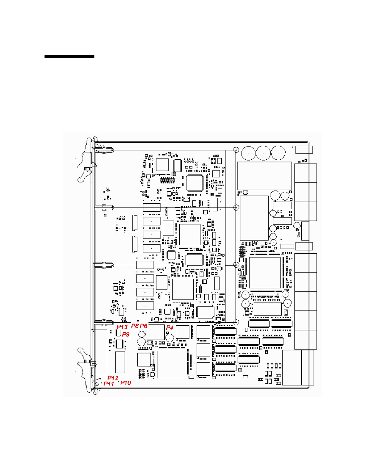
Chapter 3 Configuring Jumper Settings 3-7
3.2 Jumper Locations
FIGURE 3-1 shows the locations of the jumper settings.
FIGURE 3-1 Switch Jumper Locations
Page 78

3-8 Sun Netra CP3240 Switch Installation Guide • September 2009
Page 79

4-1
CHAPTER
4
Configuring Switch Software
This chapter describes how to configure the switch software.
The switch incorporates four main software components:
■ IPMI firmware, which runs on a separate microcontroller.
■ uBoot loads the boot for the system. It can be compared to a BIOS on a node
board.
■ Operating system (OS), which uses Monta Vista 3.1 Pro, based on the 2.4.20 Linux
kernel.
■ LVL7 Systems’ FASTPATH software, which provides all of the management and
control features of the switch.
The IPMI firmware, uBoot, and OS are covered in this chapter. FASTPATH is
described, however, for detailed information and command syntax, refer to the Netra
CP3240 Switch Command Reference Manual (820-3253).
This chapter contains the following topics:
■ Section 4.1, “IPMI Firmware Sensors” on page 4-2
■ Section 4.2, “uBoot” on page 4-5
■ Section 4.3, “Linux” on page 4-7
■ Section 4.4, “Serial Select” on page 4-8
■ Section 4.5, “Serial Location” on page 4-9
■ Section 4.6, “Boot Sequence” on page 4-10
■ Section 4.7, “Primary and Backup Flash” on page 4-13
■ Section 4.8, “Dual Firmware Images” on page 4-13
■ Section 4.9, “Network Boot” on page 4-14
■ Section 4.10, “FASTPATH” on page 4-18
■ Section 4.11, “Firmware Updates” on page 4-24
■ Section 4.12, “Fiber Optic RTM Configuration” on page 4-25
Page 80

4-2 Sun Netra CP3240 Switch Installation Guide • September 2009
4.1 IPMI Firmware Sensors
This section describes the IPMI firmware sensors.
4.1.1 State Sensors
TABLE 4-1 IPMI State Sensors
Sensor Name Type Description Discrete States Returned
TABLE 4-2
0
FRU 0
HOT_SWAP
State hotswap discrete
state
M state, per ATCA spec
1 RTM hotswap State hotswap discrete
state
M state, per ATCA spec
2 AMC 0
hotswap
State hotswap discrete
state
M state, per ATCA and AMC
spec
3 AMC 1
hotswap
State hotswap discrete
state
M state, per ATCA and AMC
spec
4 AMC 2
hotswap
State hotswap discrete
state
M state, per ATCA and AMC
spec
5 IPMB physical State IPMB Link sensor Defined in ATCA spec.
6 BMC Watchdog State Watchdog timer Discrete, Watchdog 2 (per the
IPMI spec)
11 RTM Presence State Rear Module
Present Signal
State 01h = Device absent, 02h
= Device present
12 Base Early* State Base firmware
signal
Asserted indicates Uboot
prompt
13 Base Full* State Base firmware
signal
Asserted indicates Linux has
booted
14 Base Good* State Base firmware
signal
Asserted indicates FASTPATH
has loaded
15 Fabric Early* State Fabric firmware
signal
Asserted indicates Uboot
prompt
16 Fabric Full* State Fabric firmware
signal
Asserted indicates Linux has
booted
17 Fabric Good* State Fabric firmware
signal
Asserted indicates FASTPATH
has loaded
Page 81

Chapter 4 Configuring Switch Software 4-3
*These sensors represent the software state of the switch.
The following tables lists the logic that drives these sensors.
TABLE 4-3 IPMI Sensor Logic
State Timeout Failover Condition Early Full Good
Initial power-on state 5 sec Uboot corrupted or
erased
001
uBoot initial state 5 sec Uboot finds no
image
000
uBoot console n/a Failover timer stops 1 0 0
Linux booted 90 sec Soft-off now occurs 0 1 0
Linux boot menu n/a Failover timer stops
(user interruption)
110
FASTPATH booted 90 sec Timer stops if this
state is reached in
time
011
Critical code update n/a An update is in
progress; the failover
time stops
111
Page 82

4-4 Sun Netra CP3240 Switch Installation Guide • September 2009
4.1.2 Threshold Sensors
TABLE 4-4 IPMI Thresold Sensors
Sensor Name Type Description Units
Lower
Thresholds
Upper
Thresholds
# Minor Major Critical Minor Major Critical
7 +12.0V Thresh +12V
main
power
Volts 11.016 10.21 9.02 13.45 13.72 13.77
8 +3.3V Thresh +3.3V line Volts 3.126 3.02 2.914 3.563 3.654 3.805
9 +2.5V Thresh +2.5V line Volts 2.308 2.202 2.106 2.701 2.808 2.904
10 +1.25V Thresh +1.25V
line
Volts 1.156 1.009 0.7546 1.5582 1.754 1.9502
18 Base
CPU
Temp
Thresh Base CPU
Temp
o
C n/a n/a n/a 60 70 80
19 RTM
temp
Thresh RTM
Temperatu
re
o
C n/a n/a n/a 55 65 75
20 Fabric
CPU
Temp
Thresh Fabric
CPU Temp
o
C n/a n/a n/a 60 70 80
21 +1.5V Thresh +1.5V line Volts 1.4014 1.303 1.1074 1.6072 1.7052 1.9012
22 +1.8V Thresh +1.8V line Volts 1.656 1.509 1.303 1.9502 2.107 2.303
23 +1.0V Thresh +1.0V line Volts 0.902 0.706 0.51 1.1074 1.303 1.509
24 +1.2V Thresh +1.2V line Volts 1.107 1.009 0.804 1.303 1.4014 1.607
25 Site 1
Pwr
Cur
Thresh AMC Slot
current
sense
Amps n/a n/a n/a 5.5 6.023 6.517
26 Site 1
Pwr
Thresh AMC Slot
+12V
Volts n/a n/a n/a 13.048 13.44 13.608
27 Site 1MPThresh AMC Slot
Managem
ent Pwr
Volts n/a n/a n/a 3.456 3.514 3.6
28 Site 2
Pwr
Cur
Thresh AMC Slot
current
sense
Amps n/a n/a n/a 5.5 6.023 6.517
29 Site 2
Pwr
Thresh AMC Slot
+12V
Volts n/a n/a n/a 13.048 13.44 13.608
Page 83

Chapter 4 Configuring Switch Software 4-5
4.2 uBoot
uBoot is the boot loader. Much like a BIOS, it brings the system to a usable state for
the operating system (OS) to boot. It also performs a POST of the CPU subsystem. It
can be used as a recovery console if the firmware image becomes corrupt or a
firmware update fails. Several important environment variables are stored in uBoot,
only some of which should ever be changed, namely noekey and baudrate.
4.2.1 uBoot Console
To get to a uBoot console, you must prevent the switch from booting into the OS.
Shown here is an example of the start of a boot sequence.
Press any key before ### JFFS2 loading 'image1' to 0x400000 appears.
30 Site 2MPThresh AMC Slot
Managem
ent Pwr
Volts n/a n/a n/a 3.456 3.514 3.6
31 Site 3
Pwr
Cur
Thresh AMC Slot
current
sense
Amps n/a n/a n/a 5.5 6.023 6.517
32 Site 3
Pwr
Thresh AMC Slot
+12V
Volts n/a n/a n/a 13.048 13.44 13.608
33 Site 3MPThresh AMC Slot
Managem
ent Pwr
Volts n/a n/a n/a 3.456 3.514 3.6
CPU: 400 MHz
DRAM: 256 MB
FLASH: 64 MB, Base, Primary Flash
### JFFS2 loading 'image1' to 0x400000
Scanning JFFS2 FS: . done.
### JFFS2 load complete: 10026940 bytes loaded to 0x400000
Booting ...
Loading Ramdisk to 0fdf6000, end 0ff8d551 ... OK
TABLE 4-4 IPMI Thresold Sensors (Continued)
Sensor Name Type Description Units
Lower
Thresholds
Upper
Thresholds
Page 84

4-6 Sun Netra CP3240 Switch Installation Guide • September 2009
There is only a one-second delay to press a key.
When the uBoot prompt is displayed, you can then enter any of the following
commands.
4.2.2 E-Keying Control in uBoot
See the Section 4.3.1, “e-Keying” on page 4-7 for a description of e-Keying, and how
it is supported.
To disable e-Keying, use the noekey environment variable.
List the ports to be disabled separated by only commas.
Or use the word all to disable e-Keying completely.
To re-enable e-Keying clear the variable.
After changing the environment variables you must always save if you would like
the change to persist though a reset.
TABLE 4-5 uBoot Console Commands
Command Result
print or
printenv
Shows the current environment variables.
set
<variable>
or setenv
Followed by an environment variable, this command changes the
environment variable.
save or
saveenv
Writes the variables to flash. You must save the changes if you want them
to persist through a reset.
set noekey 1,2,3,4
set noekey all
set noekey
Page 85

Chapter 4 Configuring Switch Software 4-7
4.2.3 Serial-Baud Rate Control in uBoot
You can change the serial baud rate from within FASTPATH, the boot menu, or in
uBoot. Changing it in uBoot is the only method that allows it to persist through a
reset. Only standard baud rates are accepted.
Note – Change the baud rate on the Fabric first, then on the Base. If the baud rate
on the Fabric and Base do not match, the Fabric will not be accessible. If the Fabric is
not accessible, change the baud rate on the Base until the Fabric is accessible.
To change the baud rate in uBoot, enter the command as in the following example.
After changing the rate, you must save if you would like the change to persist
though a reset.
4.3 Linux
The switch uses Linux as an operating system. The Monta Vista 3.1 Pro 2.4.20 kernel
is used. There are no settings to change, and the OS is completely transparent to the
user.
4.3.1 e-Keying
e-Keying is implemented as a Linux driver. The CPUs for both Base and Fabric have
a direct connection to the IPMI controller, which is used to communicate e-Keying
messages. The CPU is interrupted when an e-Keying event occurs. The driver
handles these interrupts and disables ports based on the information it receives. This
disables the port at the PHY level. e-Keying can be ignored by creating a uBoot
environment variable as described in the Section 4.2.2, “E-Keying Control in uBoot”
on page 4-6.
set baudrate <115200>
Page 86

4-8 Sun Netra CP3240 Switch Installation Guide • September 2009
4.3.2 e-Keying Bypass
e-Keying can be ignored by creating a uBoot environment variable as described in
Section 4.2.2, “E-Keying Control in uBoot” on page 4-6. When e-Keying is bypassed,
ports are no longer enabled or disabled based on the e-Keying state. The e-Keying
information is still shared with the shelf manager as usual, but now ports are
enabled regardless if the shelf manager enables them or not.
4.3.3 ATCA LEDs
The ATCA LEDs can be turned on from several sources, one of which is a Linux
driver. Both the Base and Fabric drive these LEDs. The red OOS LED is driven until
FASTPATH has loaded, at which point the green Healthy LED is driven. The OOS
LED signals are “OR” so that if one or more are active, the LED is on. The Healthy
LED signals are “AND.” The Base and Fabric must be booted into FASTPATH as
well as several hardware conditions must be met for this LED to be on.
4.4 Serial Select
A single-serial port is provided to control both CPUs. The ` key, usually in the
upper left key on the keyboard and the same key as ~, can be used to switch
between controlling the Base (3.0) and the Fabric (3.1). The ` key works in uBoot,
Linux, the BCM debug shell, and FASTPATH.
When you switch between Base and Fabric [Base] or [Fabric] is printed to the
console so that you know which one you are currently controlling.
(switch Base) #
(and then ENTER is pressed here)
(switch Base) #[Fabric]
(and then ENTER is pressed here)
(switch Fabric) #[ Base ]
(switch Base) #
User:
Page 87

Chapter 4 Configuring Switch Software 4-9
4.5 Serial Location
The switch supports running its serial port to both the front panel and the RTM. It
does not support both the front panel and RTM at the same time. You must
configure the port to go to the location needed. By default, the port is routed to the
front panel.
4.5.1 Changing Serial Location from UBoot
In this example, the serial port direction is to the RTM.
4.5.2 Changing Serial Location from FASTPATH
In this example, the serial port direction is changed to the RTM. Note that the
change is instantaneous and lasts though a reboot.
CODE EXAMPLE 4-1 Serial Port Change from uBoot
CPU: 400 MHz
DRAM: 256 MB
FLASH: 64 MB, Base, Primary Flash
Use the [`] key above the TAB key to switch between BASE and FABRIC.
[Break UBoot by pressing a key when the switch boots]
=> set console rtm
[set console to front for the front panel]
=> save
Saving Environment to Flash...
Un-Protected 1 sectors
Erasing Flash...
. done
Erased 1 sectors
Writing to Flash... done
Protected 1 sectors
=> boot
CODE EXAMPLE 4-2 Serial Port Change from FASTPATH
configure
lineconfig
serial location rtm
[set location to front for the front panel]
Page 88

4-10 Sun Netra CP3240 Switch Installation Guide • September 2009
4.6 Boot Sequence
The following is an example of a boot sequence.
CODE EXAMPLE 4-3 Boot Sequence Example
CPU: 400 MHz
DRAM: 256 MB
FLASH: 64 MB, Base, Primary Flash
### JFFS2 loading 'image1' to 0x400000
Scanning JFFS2 FS: . done.
### JFFS2 load complete: 10026500 bytes loaded to 0x400000
Booting ...
Loading Ramdisk to 0fdf6000, end 0ff8d4c2 ... OK
Mounting /dev/mtdblock2 at /mnt/fastpath...done.
Mounting tmpfs at /mnt/application...done.
*****************************************************************
***
* Use the [`] key above the TAB to switch between BASE and FABRIC. *
*****************************************************************
***
switch, Base, Primary Flash, image1
Select startup mode. If no selection is made within 5 seconds,
the Application will start automatically...
--- Main Menu ---
1 - Start Switch Application
2 - Display Utility Menu
Select (1, 2):
Extracting Application from image1.....done
Loading Application...done.
SOC unit 0 attached to PCI device BCM56503_B2
FASTPATH starting...started!
(Unit 1)>
User:
Page 89

Chapter 4 Configuring Switch Software 4-11
The switch takes approximately 50 seconds to boot to a console and be fully
functional.
4.6.1 Boot Utility Menu
There is a utility menu that can be used before FASTPATH boots. During boot there
is a two-option menu displayed for five seconds. This menu allows access to the
utility menu if you press number 2 and Enter.
Most of the options are self explanatory based on their names. The following
sections describe some of the options more fully.
CODE EXAMPLE 4-4 Boot Utility Menu Access
switch, Base, Primary Flash, image2
--- Utility Menu ---
1 - Start Switch Application
2 - Load Code Update Package using TFTP/FTP
3 - Load Code Update Package using XMODEM/YMODEM/ZMODEM
4 - Copy Primary Flash to Backup Flash
5 - Select Serial Speed
6 - Retrieve Error Log using TFTP
7 - Retrieve Error Log using XMODEM/YMODEM/ZMODEM
8 - Erase Current Configuration
9 - Erase Permanent Storage
10 - Select Boot Method
11 - Activate Backup Image
12 - Start Diagnostic Application
13 - Reboot
Select option (1-13):
Page 90

4-12 Sun Netra CP3240 Switch Installation Guide • September 2009
4.6.1.1 Load Code Update Package using TFTP/FTP
FASTPATH can be updated from within FASTPATH itself, but it can also be updated
from this menu.
■ The update image must be on a TFTP server or FTP server.
■ The server must be on the same network as the out-of-band management port.
■ You need to have the IP of the server, the desired IP of the board being updated,
the gateway (if needed), and the file name.
Note – DHCP can be used to obtain an IP for the switch during this update. Enter
dhcp as the IP address. This entry begins the update and provides status
information as it is updating.
4.6.1.2 Erase Current Configuration
This is the same as clear config from within FASTPATH. This option can be used
if the switch is in an unknown state, and restoring the default settings is desired.
4.6.1.3 Erase Permanent Storage
This command completely erases FASTPATH, any log files, and any configurations.
It does not erase uBoot or Linux. Use of this command is never recommended.
Updates can safely be installed without running this option, and configurations and
log files are preserved.
4.6.1.4 Select Boot Method
The switch supports three boot methods:
■ from the local image on the flash
■ from an image over the network
■ from an image over the serial port
The default option is booting from the flash. See Section 4.9, “Network Boot” on
page 4-14 for more information.
Page 91
Chapter 4 Configuring Switch Software 4-13
4.6.1.5 Start Diagnostic Application
This option boots the Broadcom diag shell, currently SDK version 5.4.1. This
environment is provided as is, with no support. Several commands provided in this
shell are not supported and will not work. This shell is provided mainly for debug,
testing, and diagnostics purposes. This shell has many low-level tests, and low-level
register access. It can be used to check the integrity of particular boards. Help is
provided in the shell with ?? and commands followed by a single question mark.
Some commands of interest are TestList and TestRun.
4.7 Primary and Backup Flash
The switch features hardware flash redundancy. If the switch fails to boot from the
primary flash for any reason, the onboard IPMC will reset the board and attempt to
boot out of the backup flash. No user interaction is required.
The switch backup flash comes preprogrammed with default settings. You can
change what is loaded on the backup flash by using the Copy Primary Flash to
Backup Flash command from the utility menu.
4.8 Dual Firmware Images
The switch supports dual firmware images of the Base and Fabric software. While
this feature does not provide high availability (the hardware redundant flash
provides that), it does provide a way to store two copies of the firmware on the
switch. This allows you to switch between firmware, as needed.
4.8.1 Booting the Non-Active Image
Which image is active can be changed several ways.
From the boot menu, the Activate Backup Image option can be used.
From within FASTPATH the boot system command in combination with the
update bootcode commands can be used.
Page 92

4-14 Sun Netra CP3240 Switch Installation Guide • September 2009
4.8.2 Updating the Non-Active Image
All of the update methods supported by the active image (image1 by default) are
also supported for the non-active image (image2).
4.8.3 Fabric 1G/10G Auto-negotiation
The Fabric networks support both 1Gigabyte and 10Gigabyte operation. No
configuration is required to put the switch into either a 1Gigabyte or 10Gigabyte
mode. The switch will dynamically connect at the appropriate speed.
4.9 Network Boot
The switch supports network booting. This feature can be used to test updates to
FASTPATH without installing them. Updates containing changes to uBoot, Linux, or
the IPMC must be installed to the flash before they can be used.
1. Setup a TFTP server on the update network.
Tftpd is the standard TFTP server for Linux and Solaris.
For Windows, Solarwinds (
http://www.solarwinds.net) offers a free TFTP server.
2. Place the update image on the TFTP server.
It will have a .tgz file extension.
3. Connect to the serial management port of the network to be updated, and
connect the MGMT port to the update network.
4. Reboot the switch using the reboot button, hotswap handle, or reload
command.
5. As the switch boots, press number 2 to enter the Utility Menu.
6. Press number 8 to change the boot method.
7. Press number 3 to select network as the boot method.
8. Enter the information for your TFTP server.
For host IP, you can enter dhcp if you would like to use DHCP to obtain a valid
IP address.
Page 93

Chapter 4 Configuring Switch Software 4-15
9. Press number 1 to boot the system.
CODE EXAMPLE 4-5 Example Console Output
CPU: 400 MHz
DRAM: 256 MB
FLASH: 64 MB, Base, Primary Flash
### JFFS2 loading 'image1' to 0x400000
Scanning JFFS2 FS: . done.
### JFFS2 load complete: 10026500 bytes loaded to 0x400000
Booting ...
Loading Ramdisk to 0fdf6000, end 0ff8d4c2 ... OK
Mounting /dev/mtdblock2 at /mnt/fastpath...done.
Mounting tmpfs at /mnt/application...done.
*****************************************************************
***
* Use the [`] key above the TAB to switch between BASE and FABRIC. *
*****************************************************************
***
switch, Base, Primary Flash, image1
Select startup mode. If no selection is made within 5 seconds,
the Application will start automatically...
--- Main Menu ---
1 - Start Switch Application
2 - Display Utility Menu
Select (1, 2): 2
*****************************************************************
***
* Use the [`] key above the TAB to switch between BASE and FABRIC. *
*****************************************************************
***
switch, Base, Primary Flash, image1
--- Utility Menu ---
1 - Start Switch Application
2 - Load Code Update Package using TFTP/FTP
3 - Load Code Update Package using XMODEM/YMODEM/ZMODEM
4 - Copy Primary Flash to Backup Flash
5 - Select Serial Speed
Page 94

4-16 Sun Netra CP3240 Switch Installation Guide • September 2009
6 - Retrieve Error Log using TFTP
7 - Retrieve Error Log using XMODEM/YMODEM/ZMODEM
8 - Erase Current Configuration
9 - Erase Permanent Storage
10 - Select Boot Method
11 - Activate Backup Image
12 - Start Diagnostic Application
13 - Reboot
Select option (1-13): 10
Current Boot Method: FLASH
1 - Flash Boot
2 - Network Boot
3 - Serial Boot
4 - Exit without change
Select option (1-4): 2
Enter Server IP []:10.10.3.199
Enter Host IP (# or dhcp) []:dhcp
Enter Transfer Method (tftp or ftp) [ftp]:
Enter Filename []:/switch.1.0.1.0.stk
Accept changes? Press(Y/N): y
*****************************************************************
***
* Use the [`] key above the TAB to switch between BASE and FABRIC. *
*****************************************************************
***
switch, Base, Primary Flash, image1
--- Utility Menu ---
1 - Start Switch Application
2 - Load Code Update Package using TFTP/FTP
3 - Load Code Update Package using XMODEM/YMODEM/ZMODEM
4 - Copy Primary Flash to Backup Flash
5 - Select Serial Speed
6 - Retrieve Error Log using TFTP
7 - Retrieve Error Log using XMODEM/YMODEM/ZMODEM
8 - Erase Current Configuration
9 - Erase Permanent Storage
10 - Select Boot Method
11 - Activate Backup Image
12 - Start Diagnostic Application
13 - Reboot
CODE EXAMPLE 4-5 Example Console Output (Continued)
Page 95

Chapter 4 Configuring Switch Software 4-17
10. Use option 8 of the Utility Menu to change the boot method back to flash, when
desired.
Select option (1-13): 1
Creating tmpfs filesystem on tmpfs for download...done.
Bringing up eth0 interface...done.
HOST IPADDR=10.10.2.246
Transferring '/switch.1.0.1.0.stk' from '10.10.3.199' via
ftp...done.
Bringing down eth0 interface...done.
Extracting Application...done.
Destroying tmpfs filesystem on tmpfs...done.
Loading Application...done.
SOC unit 0 attached to PCI device BCM56503_B2
FASTPATH starting...started!
(Unit 1)>
User:
CODE EXAMPLE 4-5 Example Console Output (Continued)
Page 96

4-18 Sun Netra CP3240 Switch Installation Guide • September 2009
4.10 FASTPATH
The switch features LVL7 Systems’ FASTPATH 2340 software, version 4.4.
FASTPATH is a software package providing the robust management needed to
control a modern switch-router. This section serves as a quick primer on using
FASTPATH on the switch. FASTPATH is not covered in detail in this guide, but is
covered in the Netra CP3240 Switch Command Reference Manual (820-3253).
4.10.1 Management Options
The switch can be controlled by a CLI, a web interface, and through SNMP. All
management interfaces, other than serial, can be enabled or disabled, provided over
both the out-of-band management port and/or any in-band ports, and be limited to
certain in-band ports.
4.10.1.1 CLI
The switch provides an industry standard CLI. The CLI is provided over the serial
port, telnet and SSH. This section only describes some basic commands. For detailed
command syntax, refer to the Netra CP3240 Switch Command Reference Manual
(820-3253).
The CLI is mode based. It works similarly to a console in Linux or Windows.
Commands are grouped under modes, and those commands only work when the
user is in the current mode. There are very few global commands.
To return to one mode higher than the current mode, use exit.
For example to shutdown port 17, switch to enable mode, configure mode, interface
17 mode, then issue the shutdown command. Use exit to return to configure
mode, and exit again to return to enable mode.
Many commands have a no form. The no form is used to disable the command. With
the previous example, to re-enable port 17, once you are in the interface 17 mode,
you would issue the no shutdown command.
Page 97

Chapter 4 Configuring Switch Software 4-19
4.10.2 Basic CLI Commands
TABLE 4-6 Basic CLI Commands
Command Function Mode
enable Switch to privilege mode. You must be in enabled
mode for most options.
default
show port all Show status of the ports. privilege
show interface ethernet 0/x Show detailed statistics on port 0/x. privilege
clear counters Clear all statistics. privilege
clear config Restore the default configuration. privilege
show running-config Show the current configuration of the switch.
This command shows everything that is not set to
the default value. The output is a script that can
be copied to a file for later use, or for another
switch.
privilege
copy system:running-config
nvram:startup-config
Save the current configuration though a reboot. privilege
serviceport protocol dhcp Use DHCP on the out-of band port. Only one of
the serviceport and network can use DHCP. To
enable DHCP on one, you must disable it on the
other. The same command works for network.
privilege
serviceport protocol none Use user assigned IP NOTE: the same command
works for network.
privilege
serviceport ip <ip> <netmask>
<gateway>
Force an IP for serviceport. privilege
network parms <ip> <netmask>
<gateway>
Force an IP for network. privilege
show network View the in-band management settings. privilege
show serviceport View the out-of-band management settings. privilege
serial baudrate Change the serial baudrate. privilege
vlan database Switch to vlan database mode. Create and delete
VLANs here.
privilege
vlan x Create a VLAN with number x. vlan
exit Return to one mode higher.
configure Switch to configure mode. You must be in
configure mode to change most settings.
privilege
Page 98
4-20 Sun Netra CP3240 Switch Installation Guide • September 2009
4.10.3 Logins and Prompts
FASTPATH supports multiple users with different security levels. By default, there
is one admin user with no password. In the CLI, privilege mode is
password-protected separately from the default mode, but also has a default of no
password.
4.10.3.1 CLI Defaults
A CLI is provided on the serial console, telnet console, and SSH console. The serial
console is always enabled. The telnet console is enabled by default. SSH is
disabled by default.
The prompts always show the current mode. Here are a few examples.
4.10.3.2 Web Interface Defaults
The username and password are the same as the CLI. The web interface is enabled
by default. Java is enabled by default. HTTPS is disabled by default.
interface 0/x Switch to interface mode. You must be in
interface mode to change most port specific
settings.
configure
vlan participation include x Add interface to VLAN x. interface
vlan pvid x Change interface’s pvid to VLAN x. interface
Username:admin
Password:
>enable
Password:
#
default mode
# privilege mode
# configure mode
(interface 0/2)
# interface 0/2 mode
TABLE 4-6 Basic CLI Commands (Continued)
Page 99

Chapter 4 Configuring Switch Software 4-21
4.10.3.3 SNMP Defaults
SNMP is enabled by default. The default read-only community string is public.
The default read-write community string is private.
4.10.4 Secure Remote Access
4.10.4.1 SSH and SSL/TLS Keys
The switch supports SSH for a secure CLI console as well as SSL/TLS for secure
HTTP. By default, SSH and SSL are disabled. The switch cannot generate its own
keys. Keys must be generated on an external PC, and uploaded to the switch via
TFTP. Once the keys are on the switch, SSH and HTTPS must be enabled to be used.
4.10.4.2 Enabling SSH and SSL
First, the certifications and keys must be uploaded to the switch using a command
such as the following:
Upload the following files to the switch:.
Enable secure access (SSH/Telnet) and disable non-secure access (SSL/HTTP).
copy tftp://<ip>/<file> <location>
File Location
rsa1.key nvram:sshkey-rsa1
rsa2.key nvram:sshkey-rsa2
dsa.key nvram:sshkey-dsa
dh512.pem nvram:sslpem-dhweak
dh1024.pem nvram:sslpem-dhstrong
server.pem nvram:sslpem-server
rootcert.pem nvram:sslpem-root
ip ssh
configure
Page 100

4-22 Sun Netra CP3240 Switch Installation Guide • September 2009
4.10.5 Default Settings
The switch comes configured with a default configuration. This configuration boots
the board to Layer 2 switching. This configuration is very basic and should be
updated for your environment. The default settings are as follows:
■ every port is in VLAN 1
■ every port is configured in switching mode
■ management interfaces are enabled
■ spanning-tree is enabled on every port
■ everything else is disabled
The settings of the switch can be checked with the show running-config
command. This command shows how the current configuration is different than the
default configuration. This command can be very useful because the output is in
script format. This output can be backed up or copied to another switch.
4.10.6 Port Ordering
The ports are ordered the same way as the ATCA channels. The ATCA specification
allows for backplanes to be routed differently. This means that logical slots and
physical slots often do not match.
The switch supports an abstraction layer that allows the port order to be changed.
This allows vendors to match logical slots and physical slots independent of routing.
Contact Sun if you would like a non-standard port order. Sun’s port ordering is
shown in the following table for shelves with middle hub slots, that is, slots 7 and 8.
lineconfig
no transport input telnet
exit
ip http secure-server
no ip http server
TABLE 4-7 Port Order List
Shelf Physical Slot Base Port Fabric Port
11312
21110
 Loading...