

Page 1

SunLink™ SNA 9.1 PU2.1 Server
Configuration Guide
Sun Microsystems Computer Company
A Sun Microsystems, Inc. Business
2550 Garcia Avenue
Mountain View, CA 94043 USA
415 960-1300 fax 415 969-9131
Part No.: 802-2673-12
Revision A, August 1997
Page 2

Copyright 1997 Sun Microsystems, Inc. 2550 Garcia A venue, Mountain V iew, California 94043-1 100 U.S.A. All rights reserved.
This product or document is protected by copyright and distributed under licenses restricting its use, copying, distribution, and decompilation.
No part of this product or document may be reproduced in any form by any means without prior written authorization of Sun and its licensors,
if any . Third-party software, including font technology, is copyrighted and licensed from Sun suppliers.
Parts of this product may be derived from Berkeley BSD systems, licensed from the University of California. UNIX is a register ed trademark in
the U. S. and other countries, exclusively licensed through X/Open Company Ltd.
RESTRICTED RIGHTS: Use, duplication, or disclosure by the U.S. Government is subject to restrictions of F AR 52.22714(g)(2)(6/87) and FAR 52.227-19(6/87), or DFAR 252.227-7015(b)(6/95) and DFAR 227.7202-3(a).
Sun, Sun Microsystems, the Sun logo, AnswerBook, SunDocs, SunLink, OpenWindows, and Solaris ar e trademarks, registered trademarks, or
service marks of Sun Microsystems, Inc. in the U. S. and other countries. All SP ARC trademarks are used under license and are trademarks or
registered trademarks of SP ARC International, Inc. in the U. S. and other countries. Products bearing SPARC trademarks are based upon an
architecture developed by Sun Microsystems, Inc.
The OPEN LOOK and Sun™ Graphical User Interface was developed by Sun Microsystems, Inc. for its users and licensees. Sun acknowledges
the pioneering efforts of Xerox in researching and developing the concept of visual or graphical user interfaces for the computer industry. Sun
holds a non-exclusive license from Xerox to the Xerox Graphical User Interface, which license also covers Sun’s licensees who implement OPEN
LOOK GUIs and otherwise comply with Sun’s written license agreements.
DOCUMENTATION IS PROVIDED “AS IS” AND ALL EXPRESS OR IMPLIED CONDITIONS, REPRESENTATIONS AND WARRANTIES,
INCLUDING ANY IMPLIED WARRANTY OF MERCHANTABILITY, FITNESS FOR A PARTICULAR PURPOSE OR
NON-INFRINGEMENT, ARE DISCLAIMED, EXCEPT TO THE EXTENT THAT SUCH DISCLAIMERS ARE HELD TO BE LEGALLY
INVALID.
Copyright 1997 Sun Microsystems, Inc., 2550 Garcia A venue, Mountain V iew, Californie 94043-1100 U.S.A. T ous droits réservés.
Ce produit ou document est protégé par un copyright et distribué avec des licences qui en restreignent l’utilisation, la copie et la décompilation.
Aucune partie de ce produit ou de sa documentation associée ne peut être reproduite sous aucune forme, par quelque moyen que ce soit, sans
l’autorisation préalable et écrite de Sun et de ses bailleurs de licence, s’il y en a.
Des parties de ce produit pourront être derivées du système UNIX
l’Université de Californie. UNIX est une marque enregistrée aux Etats-Unis et dans d’autres pays, et licenciée exclusivement par X/Open
Company Ltd. Le logiciel détenu par des tiers, et qui comprend la technologie relative aux polices de caractères, est protégé par un copyright et
licencié par des fournisseurs de Sun.
Sun, Sun Microsystems, le logo Sun, AnswerBook, SunDocs, SunLink, OpenWindows, et Solaris sont des mar ques déposées ou enregistrées de
Sun Microsystems, Inc. aux Etats-Unis et dans d’autres pays. T outes les marques SPARC, utilisées sous licence, sont des marques déposées ou
enregistrées de SP ARC International, Inc. aux Etats-Unis et dans d’autres pays. Les produits portant les mar ques SP ARC sont basés sur une
architecture développée par Sun Microsystems, Inc.
®
licencié par Novell, Inc. et du système Berkeley 4.3 BSD licencié par
Les utilisateurs d’interfaces graphiques OPEN LOOK® et Sun™ ont été développés de Sun Microsystems, Inc. pour ses
utilisateurs et licenciés. Sun reconnaît les efforts de pionniers de Xerox Corporation pour la recher che et le développement du
concept des interfaces d’utilisation visuelle ou graphique pour l’industrie de l’informatique. Sun détient une licence non
exclusive de Xerox sur l’interface d’utilisation graphique, cette licence couvrant aussi les licenciés de Sun qui mettent en place les
utilisateurs d’interfaces graphiques OPEN LOOK et qui en outre se conforment aux licences écrites de Sun.
CETTE PUBLICATION EST FOURNIE "EN L’ETAT" SANS GARANTIE D’AUCUNE SORTE, NI EXPRESSE NI IMPLICITE, Y COMPRIS,
ET SANS QUE CETTE LISTE NE SOIT LIMITATIVE, DES GARANTIES CONCERNANT LA VALEUR MARCHANDE, L’APTITUDE DES
PRODUITS A REPONDRE A UNE UTILISATION PARTICULIERE OU LE FAIT QU’ILS NE SOIENT PAS CONTREFAISANTS DE PRODUITS
DE TIERS.
Please
Recycle
Page 3

Contents
Preface. . . . . . . . . . . . . . . . . . . . . . . . . . . . . . . . . . . . . . . . . . . . . . . xix
1. Overview . . . . . . . . . . . . . . . . . . . . . . . . . . . . . . . . . . . . . . . . . . . . 1-1
1.1 Overview. . . . . . . . . . . . . . . . . . . . . . . . . . . . . . . . . . . . . . . . 1-2
1.2 Sun PU2.1 SNA Server Components . . . . . . . . . . . . . . . . . 1-3
1.2.1 Graphical Management Interface . . . . . . . . . . . . . . . 1-3
1.2.2 Gateway Manager. . . . . . . . . . . . . . . . . . . . . . . . . . . . 1-3
1.2.3 System Manager . . . . . . . . . . . . . . . . . . . . . . . . . . . . . 1-3
1.2.4 PU2.1 Server Process. . . . . . . . . . . . . . . . . . . . . . . . . . 1-4
1.2.5 Sun Name Server. . . . . . . . . . . . . . . . . . . . . . . . . . . . . 1-4
1.2.6 Configuration Options . . . . . . . . . . . . . . . . . . . . . . . . 1-5
1.3 Systems and Servers . . . . . . . . . . . . . . . . . . . . . . . . . . . . . . . 1-7
1.4 Connection Types . . . . . . . . . . . . . . . . . . . . . . . . . . . . . . . . . 1-8
1.4.1 LAN Connections . . . . . . . . . . . . . . . . . . . . . . . . . . . . 1-8
1.4.2 SDLC Connections . . . . . . . . . . . . . . . . . . . . . . . . . . . 1-8
1.4.3 QLLC Connections . . . . . . . . . . . . . . . . . . . . . . . . . . . 1-9
iii
Page 4

1.5 PU2.1 Emulation. . . . . . . . . . . . . . . . . . . . . . . . . . . . . . . . . . 1-9
1.6 LU Emulation . . . . . . . . . . . . . . . . . . . . . . . . . . . . . . . . . . . . 1-10
1.7 LU Pools. . . . . . . . . . . . . . . . . . . . . . . . . . . . . . . . . . . . . . . . . 1-11
1.8 Users and User Groups . . . . . . . . . . . . . . . . . . . . . . . . . . . . 1-12
1.9 Supported Clients. . . . . . . . . . . . . . . . . . . . . . . . . . . . . . . . . 1-14
1.9.1 Traditional Telnet 3270 . . . . . . . . . . . . . . . . . . . . . . . . 1-14
1.9.2 Extended Telnet 3270E . . . . . . . . . . . . . . . . . . . . . . . . 1-15
1.9.3 Sun 3270 . . . . . . . . . . . . . . . . . . . . . . . . . . . . . . . . . . . . 1-16
1.9.4 Sun 3770/RJE. . . . . . . . . . . . . . . . . . . . . . . . . . . . . . . . 1-16
1.9.5 Sun APPC . . . . . . . . . . . . . . . . . . . . . . . . . . . . . . . . . . . 1-17
1.9.6 Telnet 5250 and Sun 5250 . . . . . . . . . . . . . . . . . . . . . . 1-18
1.9.7 File Transfer Protocol . . . . . . . . . . . . . . . . . . . . . . . . . 1-18
1.9.8 Other Sun SNA Clients. . . . . . . . . . . . . . . . . . . . . . . . 1-19
1.10 Manager Network . . . . . . . . . . . . . . . . . . . . . . . . . . . . . . . . 1-19
iv SunLink SNA 9.1 PU2.1 Server Configuration Guide—August 1997
1.11 Peer-to-Peer Operations. . . . . . . . . . . . . . . . . . . . . . . . . . . . 1-21
2. Using the Administration Program . . . . . . . . . . . . . . . . . . . . . . 2-1
2.1 Starting the Graphical Management Interface . . . . . . . . . 2-1
2.2 Using the Main Window . . . . . . . . . . . . . . . . . . . . . . . . . . . 2-3
2.3 Using Sub-Windows. . . . . . . . . . . . . . . . . . . . . . . . . . . . . . . 2-5
2.3.1 Configuration Window. . . . . . . . . . . . . . . . . . . . . . . . 2-5
2.3.2 Managers Window . . . . . . . . . . . . . . . . . . . . . . . . . . . 2-6
2.3.3 Applications Window. . . . . . . . . . . . . . . . . . . . . . . . . 2-6
2.3.4 Traces Window . . . . . . . . . . . . . . . . . . . . . . . . . . . . . . 2-7
2.3.5 Events Window. . . . . . . . . . . . . . . . . . . . . . . . . . . . . . 2-7
Page 5

2.3.6 Resource Window . . . . . . . . . . . . . . . . . . . . . . . . . . . . 2-8
2.4 Managing Windows. . . . . . . . . . . . . . . . . . . . . . . . . . . . . . . 2-9
2.5 Selecting Items . . . . . . . . . . . . . . . . . . . . . . . . . . . . . . . . . . . 2-10
2.6 Initiating Actions . . . . . . . . . . . . . . . . . . . . . . . . . . . . . . . . . 2-10
2.6.1 Toolbar Buttons . . . . . . . . . . . . . . . . . . . . . . . . . . . . . . 2-11
2.6.2 Menu Commands . . . . . . . . . . . . . . . . . . . . . . . . . . . . 2-12
2.7 Using Dialog Boxes . . . . . . . . . . . . . . . . . . . . . . . . . . . . . . . 2-16
3. Getting Started . . . . . . . . . . . . . . . . . . . . . . . . . . . . . . . . . . . . . . . 3-1
3.1 Overview of Configuration Tasks. . . . . . . . . . . . . . . . . . . . 3-2
3.2 Starting the SunGMAN . . . . . . . . . . . . . . . . . . . . . . . . . . . . 3-3
3.3 Starting the SunGMI . . . . . . . . . . . . . . . . . . . . . . . . . . . . . . 3-4
3.4 Creating a Configuration. . . . . . . . . . . . . . . . . . . . . . . . . . . 3-4
3.4.1 Creating a Manager System. . . . . . . . . . . . . . . . . . . . 3-4
3.4.2 Configuring a System . . . . . . . . . . . . . . . . . . . . . . . . . 3-5
Contents v
3.4.3 Adding a PU2.1 Server. . . . . . . . . . . . . . . . . . . . . . . . 3-6
3.4.4 Adding a Connection . . . . . . . . . . . . . . . . . . . . . . . . . 3-7
3.4.5 Adding a PU . . . . . . . . . . . . . . . . . . . . . . . . . . . . . . . . 3-10
3.4.6 Adding a Dependent LU . . . . . . . . . . . . . . . . . . . . . . 3-11
3.4.7 Saving the New Configuration . . . . . . . . . . . . . . . . . 3-13
4. Configuring Systems . . . . . . . . . . . . . . . . . . . . . . . . . . . . . . . . . . 4-1
4.1 Basic System Configuration . . . . . . . . . . . . . . . . . . . . . . . . 4-2
4.2 Advanced System Configuration . . . . . . . . . . . . . . . . . . . . 4-3
4.3 Using APPC File Transfer Protocol . . . . . . . . . . . . . . . . . . 4-5
4.3.1 Sample setup for VM/ESA . . . . . . . . . . . . . . . . . . . . 4-6
Page 6

4.3.2 Connecting to the SunLink 9.1 AFTP Client
and transferring files. . . . . . . . . . . . . . . . . . . . . . . . . . 4-10
5. Configuring PU2.1 Servers . . . . . . . . . . . . . . . . . . . . . . . . . . . . . 5-1
5.1 Basic PU2.1 Server Configuration. . . . . . . . . . . . . . . . . . . . 5-2
5.2 Advanced PU2.1 Server Configuration . . . . . . . . . . . . . . . 5-3
6. Configuring Connections. . . . . . . . . . . . . . . . . . . . . . . . . . . . . . . 6-1
6.1 Adding a LAN Connection . . . . . . . . . . . . . . . . . . . . . . . . . 6-1
6.1.1 Basic LAN Configuration. . . . . . . . . . . . . . . . . . . . . . 6-2
6.1.2 Advanced LAN Configuration . . . . . . . . . . . . . . . . . 6-3
6.2 Adding an SDLC Connection . . . . . . . . . . . . . . . . . . . . . . . 6-4
6.2.1 Basic SDLC Configuration . . . . . . . . . . . . . . . . . . . . . 6-5
6.2.2 Advanced SDLC Configuration . . . . . . . . . . . . . . . . 6-6
6.3 Adding a QLLC Connection . . . . . . . . . . . . . . . . . . . . . . . . 6-7
6.3.1 Basic QLLC Configuration. . . . . . . . . . . . . . . . . . . . . 6-8
6.3.2 Advanced QLLC Configuration . . . . . . . . . . . . . . . . 6-9
vi SunLink SNA 9.1 PU2.1 Server Configuration Guide—August 1997
7. Configuring PUs . . . . . . . . . . . . . . . . . . . . . . . . . . . . . . . . . . . . . . 7-1
7.1 Basic DLC (PU2) Configuration . . . . . . . . . . . . . . . . . . . . . 7-2
7.2 Advanced DLC (PU2) Configuration. . . . . . . . . . . . . . . . . 7-4
8. Configuring Dependent LUs. . . . . . . . . . . . . . . . . . . . . . . . . . . . 8-1
8.1 Adding Dependent LUs. . . . . . . . . . . . . . . . . . . . . . . . . . . . 8-2
8.1.1 Basic Dependent LU Configuration . . . . . . . . . . . . . 8-3
8.1.2 Advanced Dependent LU Configuration. . . . . . . . . 8-6
8.2 Modifying Dependent LUs . . . . . . . . . . . . . . . . . . . . . . . . . 8-8
8.3 Deleting Dependent LUs . . . . . . . . . . . . . . . . . . . . . . . . . . . 8-9
Page 7

8.4 Creating an LU Pool. . . . . . . . . . . . . . . . . . . . . . . . . . . . . . . 8-9
8.5 Modifying an LU Pool . . . . . . . . . . . . . . . . . . . . . . . . . . . . . 8-11
9. Configuring for LUType 6.2. . . . . . . . . . . . . . . . . . . . . . . . . . . . . 9-1
9.1 Configuring an Independent LU . . . . . . . . . . . . . . . . . . . . 9-2
9.1.1 Basic Independent LU Configuration. . . . . . . . . . . . 9-2
9.1.2 Advanced Independent LU Configuration . . . . . . . 9-3
9.2 Configuring a Partner LU . . . . . . . . . . . . . . . . . . . . . . . . . . 9-4
9.2.1 Basic Partner LU Configuration . . . . . . . . . . . . . . . . 9-5
9.2.2 Advanced Partner LU Configuration . . . . . . . . . . . . 9-6
9.3 Configuring the Session Mode . . . . . . . . . . . . . . . . . . . . . . 9-7
9.3.1 Basic Session Mode Configuration . . . . . . . . . . . . . . 9-8
9.3.2 Advanced Session Mode Configuration. . . . . . . . . . 9-9
9.4 Configuring an LUType 6.2 User . . . . . . . . . . . . . . . . . . . . 9-12
9.5 Configuring a Transaction Program. . . . . . . . . . . . . . . . . . 9-13
10. Configuring Users. . . . . . . . . . . . . . . . . . . . . . . . . . . . . . . . . . . . . 10-1
Contents vii
9.5.1 Basic Transaction Program Configuration . . . . . . . . 9-13
9.5.2 Advanced Transaction Program Configuration . . . 9-15
9.6 Configuring a TP Resource Access List . . . . . . . . . . . . . . . 9-18
10.1 Defining a User Record . . . . . . . . . . . . . . . . . . . . . . . . . . . . 10-1
10.1.1 Basic User Record Configuration . . . . . . . . . . . . . . . 10-2
10.1.2 Advanced User Record Configuration. . . . . . . . . . . 10-3
10.2 Setting Up a User Group . . . . . . . . . . . . . . . . . . . . . . . . . . . 10-7
10.3 Managing Users and Groups . . . . . . . . . . . . . . . . . . . . . . . 10-8
10.3.1 Modifying a User Record. . . . . . . . . . . . . . . . . . . . . . 10-8
Page 8

10.3.2 Deleting a User Record. . . . . . . . . . . . . . . . . . . . . . . . 10-9
10.3.3 Deleting a User from a Group . . . . . . . . . . . . . . . . . . 10-9
10.3.4 Deleting Access to a Dependent LU . . . . . . . . . . . . . 10-10
11. Managing the Server . . . . . . . . . . . . . . . . . . . . . . . . . . . . . . . . . . 11-1
11.1 Controlling Access to the Server. . . . . . . . . . . . . . . . . . . . . 11-1
11.1.1 Controlling Client Access . . . . . . . . . . . . . . . . . . . . . . 11-2
11.1.2 Controlling Operator Access . . . . . . . . . . . . . . . . . . . 11-5
11.2 Managing Licenses. . . . . . . . . . . . . . . . . . . . . . . . . . . . . . . . 11-6
11.2.1 Adding a License . . . . . . . . . . . . . . . . . . . . . . . . . . . . . 11-7
11.2.2 Deleting a License . . . . . . . . . . . . . . . . . . . . . . . . . . . . 11-8
11.3 Managing Manager Systems. . . . . . . . . . . . . . . . . . . . . . . . 11-8
11.3.1 Determining the Number of Manager Systems
to Define. . . . . . . . . . . . . . . . . . . . . . . . . . . . . . . . . . . . 11-8
11.3.2 Adding a Manager System. . . . . . . . . . . . . . . . . . . . . 11-9
11.3.3 Recovering from a Loss of Quorum . . . . . . . . . . . . . 11-10
viii SunLink SNA 9.1 PU2.1 Server Configuration Guide—August 1997
11.4 Managing the Active Configuration . . . . . . . . . . . . . . . . . 11-11
11.4.1 Modifying the Active Configuration . . . . . . . . . . . . 11-12
11.4.2 Saving Changes to the Active Configuration . . . . . 11-13
11.5 Managing an Off-line Configuration . . . . . . . . . . . . . . . . . 11-13
11.5.1 Creating an Off-line Configuration. . . . . . . . . . . . . . 11-14
11.5.2 Modifying an Off-line Configuration . . . . . . . . . . . . 11-15
11.5.3 Making an Off-line Configuration Active . . . . . . . . 11-16
11.6 Controlling the Status of Resources . . . . . . . . . . . . . . . . . . 11-17
Page 9

12. Troubleshooting . . . . . . . . . . . . . . . . . . . . . . . . . . . . . . . . . . . . . . 12-1
12.1 Diagnostic Tools . . . . . . . . . . . . . . . . . . . . . . . . . . . . . . . . . . 12-1
12.1.1 Resource Information Tables . . . . . . . . . . . . . . . . . . . 12-2
12.1.2 Event Log. . . . . . . . . . . . . . . . . . . . . . . . . . . . . . . . . . . 12-16
12.1.3 Line Trace . . . . . . . . . . . . . . . . . . . . . . . . . . . . . . . . . . . 12-16
12.1.4 PU2.1 Server Trace . . . . . . . . . . . . . . . . . . . . . . . . . . . 12-27
12.1.5 LU Information Screen . . . . . . . . . . . . . . . . . . . . . . . . 12-30
12.2 Error Messages . . . . . . . . . . . . . . . . . . . . . . . . . . . . . . . . . . . 12-32
12.3 Common Problems. . . . . . . . . . . . . . . . . . . . . . . . . . . . . . . . 12-32
12.3.1 The SunGMI Does Not Start . . . . . . . . . . . . . . . . . . . 12-33
12.3.2 The SunGMI Cannot Connect to the Running
Domain. . . . . . . . . . . . . . . . . . . . . . . . . . . . . . . . . . . . . 12-33
12.3.3 The suncpd Process Is Not Running. . . . . . . . . . . . . 12-34
12.3.4 The SunGMAN Process Does Not Start . . . . . . . . . . 12-34
12.3.5 The Sun PU2.1 SNA Server Configuration
Does Not Start Automatically . . . . . . . . . . . . . . . . . . 12-35
Contents ix
12.3.6 A System Fails . . . . . . . . . . . . . . . . . . . . . . . . . . . . . . . 12-35
12.3.7 A PU2.1 Server Fails . . . . . . . . . . . . . . . . . . . . . . . . . . 12-35
12.3.8 The Connection Does Not Activate or the
Connection Loops . . . . . . . . . . . . . . . . . . . . . . . . . . . . 12-36
12.3.9 The PU Does Not Activate. . . . . . . . . . . . . . . . . . . . . 12-36
12.3.10 Client Connections Are Failing . . . . . . . . . . . . . . . . . 12-36
12.4 Service Name Parameters . . . . . . . . . . . . . . . . . . . . . . . . . . 12-37
12.5 Getting Help . . . . . . . . . . . . . . . . . . . . . . . . . . . . . . . . . . . . . 12-38
12.5.1 Technical Support . . . . . . . . . . . . . . . . . . . . . . . . . . . . 12-38
Page 10

12.5.2 Professional Services. . . . . . . . . . . . . . . . . . . . . . . . . . 12-38
A. Resource Planning Forms . . . . . . . . . . . . . . . . . . . . . . . . . . . . . . A-1
A.1 Platforms Supported . . . . . . . . . . . . . . . . . . . . . . . . . . . . . . A-1
A.2 System Requirements. . . . . . . . . . . . . . . . . . . . . . . . . . . . . . A-1
A.3 Communication Devices . . . . . . . . . . . . . . . . . . . . . . . . . . . A-2
A.4 Software Components to be Installed . . . . . . . . . . . . . . . . A-2
A.5 Installation Utilities . . . . . . . . . . . . . . . . . . . . . . . . . . . . . . . A-2
A.6 Domain Planning Form . . . . . . . . . . . . . . . . . . . . . . . . . . . . A-2
A.7 Remote Systems to Connect to . . . . . . . . . . . . . . . . . . . . . . A-3
A.8 Manager Planning Form . . . . . . . . . . . . . . . . . . . . . . . . . . . A-3
A.9 Server Planning Forms. . . . . . . . . . . . . . . . . . . . . . . . . . . . . A-3
A.9.1 General Information . . . . . . . . . . . . . . . . . . . . . . . . . . A-3
A.9.2 LUType 6.2 Parameters. . . . . . . . . . . . . . . . . . . . . . . . A-4
A.9.3 LLC Parameters. . . . . . . . . . . . . . . . . . . . . . . . . . . . . . A-4
x SunLink SNA 9.1 PU2.1 Server Configuration Guide—August 1997
A.10 System Planning Form. . . . . . . . . . . . . . . . . . . . . . . . . . . . . A-4
A.10.1 General Information . . . . . . . . . . . . . . . . . . . . . . . . . . A-4
A.10.2 Independent LUs. . . . . . . . . . . . . . . . . . . . . . . . . . . . . A-5
A.10.3 Dependent LUs . . . . . . . . . . . . . . . . . . . . . . . . . . . . . . A-5
A.10.4 Partner LUs . . . . . . . . . . . . . . . . . . . . . . . . . . . . . . . . . A-5
A.10.5 Transaction Programs . . . . . . . . . . . . . . . . . . . . . . . . . A-6
A.10.6 SDLC Lines . . . . . . . . . . . . . . . . . . . . . . . . . . . . . . . . . A-7
A.10.7 LAN Connections . . . . . . . . . . . . . . . . . . . . . . . . . . . . A-8
A.11 Pool Resource Form . . . . . . . . . . . . . . . . . . . . . . . . . . . . . . . A-8
A.12 Users Resource Form . . . . . . . . . . . . . . . . . . . . . . . . . . . . . . A-8
Page 11

A.13 Group Resource Form . . . . . . . . . . . . . . . . . . . . . . . . . . . . . A-9
A.14 Client Configuration Requirements . . . . . . . . . . . . . . . . . . A-9
B. Name Resolution. . . . . . . . . . . . . . . . . . . . . . . . . . . . . . . . . . . . . . B-1
B.1 Domain Name System . . . . . . . . . . . . . . . . . . . . . . . . . . . . . B-1
B.2 Sun Name Server . . . . . . . . . . . . . . . . . . . . . . . . . . . . . . . . . B-3
B.3 Updating the DNS Configuration. . . . . . . . . . . . . . . . . . . . B-5
B.4 Using the Sun Name Server with APPC . . . . . . . . . . . . . . B-7
C. SNA Concepts . . . . . . . . . . . . . . . . . . . . . . . . . . . . . . . . . . . . . . . . C-1
C.1 Hierarchical SNA . . . . . . . . . . . . . . . . . . . . . . . . . . . . . . . . . C-1
C.1.1 Physical Components . . . . . . . . . . . . . . . . . . . . . . . . . C-2
C.1.2 Logical Components. . . . . . . . . . . . . . . . . . . . . . . . . . C-4
C.1.3 Sessions . . . . . . . . . . . . . . . . . . . . . . . . . . . . . . . . . . . . C-5
C.2 Peer-to-Peer SNA . . . . . . . . . . . . . . . . . . . . . . . . . . . . . . . . . C-6
C.2.1 Physical Components . . . . . . . . . . . . . . . . . . . . . . . . . C-6
Contents xi
C.2.2 Logical Components. . . . . . . . . . . . . . . . . . . . . . . . . . C-7
C.2.3 Sessions . . . . . . . . . . . . . . . . . . . . . . . . . . . . . . . . . . . . C-9
C.3 PU2.1 and PU2 Nodes . . . . . . . . . . . . . . . . . . . . . . . . . . . . . C-10
C.4 LEN and APPN . . . . . . . . . . . . . . . . . . . . . . . . . . . . . . . . . . . C-10
C.5 APPC and LUType 6.2 . . . . . . . . . . . . . . . . . . . . . . . . . . . . . C-11
C.5.1 Transaction Programs. . . . . . . . . . . . . . . . . . . . . . . . . C-12
C.5.2 Conversations and Verbs . . . . . . . . . . . . . . . . . . . . . . C-13
C.5.3 Sessions and Modes . . . . . . . . . . . . . . . . . . . . . . . . . . C-13
C.5.4 Independent or Dependent LUType 6.2s . . . . . . . . . C-14
Page 12

D. IBM Token Ring Concepts . . . . . . . . . . . . . . . . . . . . . . . . . . . . . D-1
D.1 Overview. . . . . . . . . . . . . . . . . . . . . . . . . . . . . . . . . . . . . . . . D-1
D.2 Frame Formats . . . . . . . . . . . . . . . . . . . . . . . . . . . . . . . . . . . D-3
D.2.1 Addressing . . . . . . . . . . . . . . . . . . . . . . . . . . . . . . . . . . D-5
D.3 Source Routing and Multiple-Ring Operation . . . . . . . . . D-7
E. Load Balancing . . . . . . . . . . . . . . . . . . . . . . . . . . . . . . . . . . . . . . . E-1
E.1 Overview. . . . . . . . . . . . . . . . . . . . . . . . . . . . . . . . . . . . . . . . E-1
E.2 Normal Load Balancing. . . . . . . . . . . . . . . . . . . . . . . . . . . . E-1
E.2.1 Normal Load Balancing Description . . . . . . . . . . . . E-2
E.2.2 Normal Load Balancing Example . . . . . . . . . . . . . . . E-2
E.3 Geographical Load Balancing. . . . . . . . . . . . . . . . . . . . . . . E-4
E.3.1 Geographical Load Balancing Description . . . . . . . E-5
E.3.2 Geographical Load Balancing Example . . . . . . . . . . E-6
F. Host Configurations . . . . . . . . . . . . . . . . . . . . . . . . . . . . . . . . . . . F-1
xii SunLink SNA 9.1 PU2.1 Server Configuration Guide—August 1997
F.1 3270 Clients . . . . . . . . . . . . . . . . . . . . . . . . . . . . . . . . . . . . . . F-1
F.2 sun3770/RJE Clients . . . . . . . . . . . . . . . . . . . . . . . . . . . . . . F-4
F.3 APPC Clients. . . . . . . . . . . . . . . . . . . . . . . . . . . . . . . . . . . . . F-6
F.3.1 Logical Unit . . . . . . . . . . . . . . . . . . . . . . . . . . . . . . . . . F-6
F.3.2 Partner LU . . . . . . . . . . . . . . . . . . . . . . . . . . . . . . . . . . F-8
F.3.3 Session Mode . . . . . . . . . . . . . . . . . . . . . . . . . . . . . . . . F-10
F.3.4 Transaction Program. . . . . . . . . . . . . . . . . . . . . . . . . . F-11
F.4 5250 Clients . . . . . . . . . . . . . . . . . . . . . . . . . . . . . . . . . . . . . . F-12
F.4.1 IBM Token Ring. . . . . . . . . . . . . . . . . . . . . . . . . . . . . . F-12
F.4.2 SDLC Connection . . . . . . . . . . . . . . . . . . . . . . . . . . . . F-14
Page 13

G. LUType 6.2 Security . . . . . . . . . . . . . . . . . . . . . . . . . . . . . . . . . . . G-1
G.1 Session-Level Security . . . . . . . . . . . . . . . . . . . . . . . . . . . . . G-1
G.2 Conversation-Level Security. . . . . . . . . . . . . . . . . . . . . . . . G-2
G.3 Security Access Verification . . . . . . . . . . . . . . . . . . . . . . . . G-4
G.4 Resource Access Verification. . . . . . . . . . . . . . . . . . . . . . . . G-4
G.5 Unix-Level Security . . . . . . . . . . . . . . . . . . . . . . . . . . . . . . . G-5
Index . . . . . . . . . . . . . . . . . . . . . . . . . . . . . . . . . . . . . . . . . . . Index-1
Contents xiii
Page 14

xiv SunLink SNA 9.1 PU2.1 Server Configuration Guide—August 1997
Page 15

Figures
Figure 1-1 Sun PU2.1 SNA Server and Clients. . . . . . . . . . . . . . . . . . . . . . . 1-2
Figure 1-2 Sample Configuration (Single System). . . . . . . . . . . . . . . . . . . . 1-5
Figure 1-3 Sample Configuration (Multiple Systems). . . . . . . . . . . . . . . . . 1-6
Figure 1-4 Sample Configuration (Manager Network). . . . . . . . . . . . . . . . 1-7
Figure 3-1 Configuration Hierarchy . . . . . . . . . . . . . . . . . . . . . . . . . . . . . . . 3-2
Figure 7-1 LAN Connection . . . . . . . . . . . . . . . . . . . . . . . . . . . . . . . . . . . . . . 7-4
Figure 7-2 SDLC or QLLC Connection . . . . . . . . . . . . . . . . . . . . . . . . . . . . . 7-5
Figure 11-1 Controlling Client Access. . . . . . . . . . . . . . . . . . . . . . . . . . . . . . . 11-4
Figure 11-2 Displaying Client Connections . . . . . . . . . . . . . . . . . . . . . . . . . . 11-5
Figure 11-3 Master and Restricted Operator . . . . . . . . . . . . . . . . . . . . . . . . . 11-6
Figure 11-4 Multiple Manager Systems . . . . . . . . . . . . . . . . . . . . . . . . . . . . . 11-10
Figure 12-1 Sample LU Information Screen . . . . . . . . . . . . . . . . . . . . . . . . . . 12-31
xv
Page 16

xvi SunLink SNA 9.1 PU2.1 Server Configuration Guide—August 1997
Page 17

Tables
Table 2-1 Window Management Tasks . . . . . . . . . . . . . . . . . . . . . . . . . . . . 2-9
Table 2-2 SunGMI Toolbar . . . . . . . . . . . . . . . . . . . . . . . . . . . . . . . . . . . . . . 2-11
Table 2-3 Dialog Action Buttons. . . . . . . . . . . . . . . . . . . . . . . . . . . . . . . . . . 2-17
Table 2-4 Keyboard Shortcuts. . . . . . . . . . . . . . . . . . . . . . . . . . . . . . . . . . . . 2-17
Table 4-1 Command Line Options. . . . . . . . . . . . . . . . . . . . . . . . . . . . . . . . 4-4
Table 5-1 Command Line Options. . . . . . . . . . . . . . . . . . . . . . . . . . . . . . . . 5-4
Table 7-1 Local Terminal ID SNA Device Types . . . . . . . . . . . . . . . . . . . . 7-6
Table 11-1 Stop and Start Results by Resource Type. . . . . . . . . . . . . . . . . . 11-18
Table 12-1 Status Table MIB Variables . . . . . . . . . . . . . . . . . . . . . . . . . . . . . 12-5
Table 12-2 RTM Table MIB Variables . . . . . . . . . . . . . . . . . . . . . . . . . . . . . . 12-15
Table 12-3 Sunscope Command Line Options. . . . . . . . . . . . . . . . . . . . . . . 12-19
Table 12-4 xterm Command Line Options . . . . . . . . . . . . . . . . . . . . . . . . . 12-21
xvii
Page 18

xviii SunLink SNA 9.1 PU2.1 Server Configuration Guide—August 1997
Page 19

Preface
This book is geared towards network administrators familiar with the SNA
protocol, Unix, Windows, and server technology and who are responsible for
the installation and maintenance of the SunLink SNA 9.1 PU2.1 server. Sun
assumes that you are familiar with network administration, network
management, and the related terminology therein.
Before You Read This Book
Ensure that you have completed the installation of the SunLink SNA 9.1
software. Refer to the SunLink SNA 9.1 End Node Planning and Installation Guide
and the SunLink SNA 9.1 for Solaris Release Notes for installation instructions.
How This Book Is Organized
This manual contains the following chapters covering the following topic
areas:
Chapter 1, “Overview,” discusses the SunLink SNA 9.1 PU2.1 server and
introduces its features and functions.
Chapter 2, “Using the Administration Program,” describes how to start the
Sun Graphical Management Interface (SunGMI), how to use the components of
the main window, describes how to manage windows, and how to use the
dialog boxes provided by the SunGMI.
xix
Page 20

Chapter 3, “Getting Started,” gets you started using the Graphical
Management Interface. Read this chapter carefully before you attempt any
administrative tasks on your server.
Chapter 4, “Configuring Systems,” describes how to configure the systems
that make up your Sun PU2.1 SNA Server.
Chapter 5, “Configuring PU2.1 Servers,” describes how to configure PU2.1
servers.
Chapter 6, “Configuring Connections,” describes how to add a Token Ring,
Ethernet, or FDDI connection, how to add a Synchronous Data Link Control
connection, and how to add a Qualified Logical Link Control connection.
Chapter 7, “Configuring PUs,” describes how to configure physical units
(PUs).
Chapter 8, “Configuring Dependent LUs,” describes how to configure a single
dependent logical unit (LU) or multiple dependent LUs, how to modify a
single dependent LU or a group of multiple LUs, how to delete a dependent
LU and how to configure an LU pool.
Chapter 9, “Configuring for LUType 6.2,” describes how to configure a local
independent logical unit (LU), how to configure a partner LU for a local
independent or dependent LU, how to configure the session mode for the LULU pair, how to configure an LUType 6.2 user that can access a local
independent or dependent LU, how to configure a transaction program (TP)
that can be accessed by a local independent or dependent LU, how to configure
a TP resource access list for a TP that requires a user ID, a profile, or a user ID
and profile security verification, and how to modify an LU pool.
Chapter 10, “Configuring Users,” describes how to define a user record, how
to set up a user group, how to modify or delete a user record, how to delete a
user from a group, and how to delete access to a dependent LU from a user or
user group.
Chapter 11, “Managing the Server,” describes how to control access to the Sun
PU2.1 SNA Server by clients (users) and by operators (system/network
administrators), how to determine the number of manager systems to define,
how to create manager systems, and how to recover when 50% or fewer of the
manager systems are available, how to modify the active configuration and
how to save and distribute the updates, how to create and modify off-line
xx SunLink SNA 9.1 PU2.1 Server Configuration Guide—August 1997
Page 21

configurations and how to activate an off-line configuration, how to start and
stop connections to the SNA network, and how to make resources unavailable
or available for client use.
Chapter 12, “Troubleshooting,” covers the diagnostic tools provided to help
you and SunLink Technical Support staff determine the cause of any problems
you may encounter. These tools include status monitoring, scope tracing, and
resource tracing, and NetView Response Time Monitor (RTM).
Appendix A, “Resource Planning Forms,” describes what you need to know
before you begin designing your network.
Appendix B, “Name Resolution,” describes the Domain Name System (DNS),
the Sun Name Server, and how to update the DNS configuration before you
use the Sun Name Server. It also describes the considerations to keep in mind
when using the Sun Name Server with APPC.
Appendix C, “SNA Concepts,” provides a high level introduction to SNA and
its components for those unfamiliar with SNA.
Appendix D, “IBM Token Ring Concepts,” outlines the basic concepts of IBM
Token Ring networking.
Appendix E, “Load Balancing,” provides a brief description of load balancing.
Appendix F, “Host Configurations,” describes how to coordinate host
configurations for 3270, 3770/RJE, APPC, and 5250 clients.
Appendix G, “LUType 6.2 Security,” describes session-level security for peer-
to-peer operations, conversation-level security for peer-to-peer operations, and
Unix-level security for peer-to-peer operations. It also shows you how to
specify minimum security requirements for peer-to-peer operations and how to
use the TP resource access list to verify resource access for peer-to-peer
operations.
Preface xxi
Page 22

T ypographic Conventions
The following table describes the typographic changes used in this book.
Typeface or
Symbol Meaning Example
Shell Prompts
AaBbCc123 The names of commands,
files, and directories;
on-screen computer output.
AaBbCc123 What you type, when
contrasted with on-screen
computer output.
AaBbCc123 Command-line variable:
replace with a real name or
value.
Book titles, new words or
terms, words to be
emphasized
Edit your .login file.
Use ls -a to list all files.
% You have mail.
% su
Password:
To delete a file, type rm filename.
Read Chapter 6 in the User’s Guide.
These are called class options.
You must be root to do this.
The following table shows the default system prompt and superuser prompt
for the C shell, Bourne shell, and Korn shell.
Shell Prompt
C shell machine_name%
C shell superuser machine_name#
Bourne shell and Korn shell $
Bourne shell and Korn shell
superuser
xxii SunLink SNA 9.1 PU2.1 Server Configuration Guide—August 1997
#
Page 23

Related Documents
The following Sun documents contain topics that relate to the information
in SunLink SNA 9.1 PU2.1 Server Configuration Guide.
Application Deliverable Partnumber
Installation SunLink SNA 9.1 End Node Planning and Installation Guide 802-2665-12
Administration SunLink SNA/X.25 9.1 Configuration and Administration Guide 802-3166-12
Configuration and user
information
Programming information SunLink Client IBM 3270 9.1 Programmer’s Guide 802-2668-12
Configuration and user
information
Configuration information SunLink SNA PU 2.1 9.1 Server Configuration Guide 802-2673-12
Reference information SunLink SNA SNM 9.1 Reference Manual 802-2674-12
Programming information SunLink LU0 9.1 API Programmer’s Guide 802-2676-12
Programming information SunLink SNA Peer to Peer LU 6.2 9.1 Programmer’s Guide 802-2680-12
Programming information SunLink SNA Peer to Peer CPI-C 9.1 Programmer’s Guide 802-2681-12
Late-breaking news SunLink SNA 9.1 for Solaris Release Notes 802-3165-12
CD-ROM insert for the
Answerbook package
CD-ROM insert SunLink SNA 9.1 Gateway CD-ROM 804-5649-10
CD-ROM insert SunLink SNA 9.1 RJE/3770 804-5650-10
CD-ROM insert SunLink SNA/SNM 804-5651-10
CD-ROM insert SunLink SNA LU 0 804-5652-10
Programming information Solstice X.25 9.0 System Administrator’s Guide 802-7565-10
Programming information SolarNet PC Protocol Services 1.1 with IPX/SPX for the
SunLink 3270 OpenClient 9.1 Configuration and User’s Guide 802-2667-12
SunLink RJE/3770 9.1 Configuration and User’s Guide 802-2672-12
CD-ROM insert for the AnswerBook version of the SunLink
SNA 9.1 product
Solaris 2.X Operating Environment
804-5670-10
802-3531-10
Preface xxiii
Page 24

Other Publications
The following are non-Sun Microsystems publications.
Systems Network Architecture
•
IBM Systems Network Architecture Concepts and Products, GC30-3072
• IBM Systems Network Architecture Technical Overview, GC30-3073
• IBM VTAM Installation and Resource Definition, SC23-0111
• IBM Network Control Program Resource Definition Guide, SC30-3349
• IBM 3174 Establishment Controller Planning Guide, GA27-3862
• IBM VTAM Operation, SC23-0113
• IBM NetView Operation, SC30-3364
• IBM 3174 Establishment Controller Functional Description, GA23-0218-11
DNS
•
DNS & Bind, Paul Albitz and Cricket Liu, O’Reilly and Associates.
LU6.2 and CPI-C
•
IBM Systems Network Architecture Transaction Programmer's Reference Manual
for LU Type 6.2, GC30-3084
• Systems Application Architecture Common Programming Interface
Communications Reference, SC26-4399
IBM Token Ring
•
X.25
•
xxiv SunLink SNA 9.1 PU2.1 Server Configuration Guide—August 1997
IBM Token-Ring Network Architecture Reference, SC30-3374
IBM X.25 Network Control Program Packet Switching Interface, Planning and
Installation, SC30-3501
Page 25

Ordering Sun Documents
SunDocsSM is a distribution program for Sun Microsystems technical
documentation. Easy, convenient ordering and quick delivery is available from
SunExpress. You can find a full listing of available documentation on the World
Wide Web: http://www.sun.com/sunexpress/
Table P-1 SunExpress Contact Information
Country Telephone Fax
United States 1-800-873-7869 1-800-944-0661
United Kingdom 0800-89-88-88 0800-89-88-87
Canada 1-800-873-7869 1-800-944-0661
France 0800-90-61-57 0800-90-61-58
Belgium 02-720-09-09 02-725-88-50
Luxembourg 32-2-720-09-09 32-2-725-88-50
Germany 01-30-81-61-91 01-30-81-61-92
The Netherlands 06-022-34-45 06-022-34-46
Sweden 020-79-57-26 020-79-57-27
Switzerland 0800-55-19-26 0800-55-19-27
Holland 06-022-34-45 06-022-34-46
Japan 0120-33-9096 0120-33-9097
Sun Welcomes Your Comments
Please use the Reader Comment Card that accompanies this document. We are
interested in improving our documentation and welcome your comments and
suggestions.
If a card is not available, you can email or fax your comments to us. Please
include the part number of your document in the subject line of your email or
fax message.
• Email: [email protected]
• Fax: SMCC Document Feedback
Preface xxv
1-415-786-6443
Page 26

xxvi SunLink SNA 9.1 PU2.1 Server Configuration Guide—August 1997
Page 27

Overview
This chapter contains the following sections:
1
• Overview - provides a brief description of the Sun PU2.1 SNA Server.
• Sun PU2.1 SNA Server Components - describes the components of the Sun
PU2.1 SNA Server that you will most frequently encounter.
• Systems and Servers - describes the meaning of configuring a system and
configuring a PU2.1 server.
• Connection Types - describes LAN, SDLC, QLLC, and channel connection
types.
• PU2.1 Emulation - describes the physical unit (PU) types supported by the
Sun PU2.1 SNA Server.
• LU Emulation - describes the logical unit types supported by the Sun PU2.1
SNA Server.
• LU Pools - describes how the Sun PU2.1 SNA Server uses LU pools.
• Users and User Groups - describes how to control access to resources by
setting up user records and user groups.
• Supported Clients - describes the clients supported by the Sun PU2.1 SNA
Server.
• Manager Network - describes how you can use multiple instances of the
Sun PU2.1 SNA Server to protect against system failure.
• Peer-to-Peer Operations - describes how the Sun PU2.1 SNA Server
supports peer-to-peer operations.
1-1
Page 28
1
1.1 Overview
The Sun PU2.1 SNA Server allows TCP/IP and SPX/IPX networked clients to
communicate with IBM SNA mainframes and midrange systems. You can
create an SNA enterprise network by distributing the server across several
networked systems and connections using different vendor platforms. By
distributing the server, you ensure that clients can access their applications
even when a system or connection fails.
Users see the distributed server as a single virtual gateway. You can manage
the SNA enterprise network as a single entity by using a graphical interface.
The Sun PU2.1 SNA Server can support tens of thousands of sessions. You can
add new systems into the distributed server environment at any time,
allowing you to add capacity incrementally as you migrate your users over
time from their current SNA access.
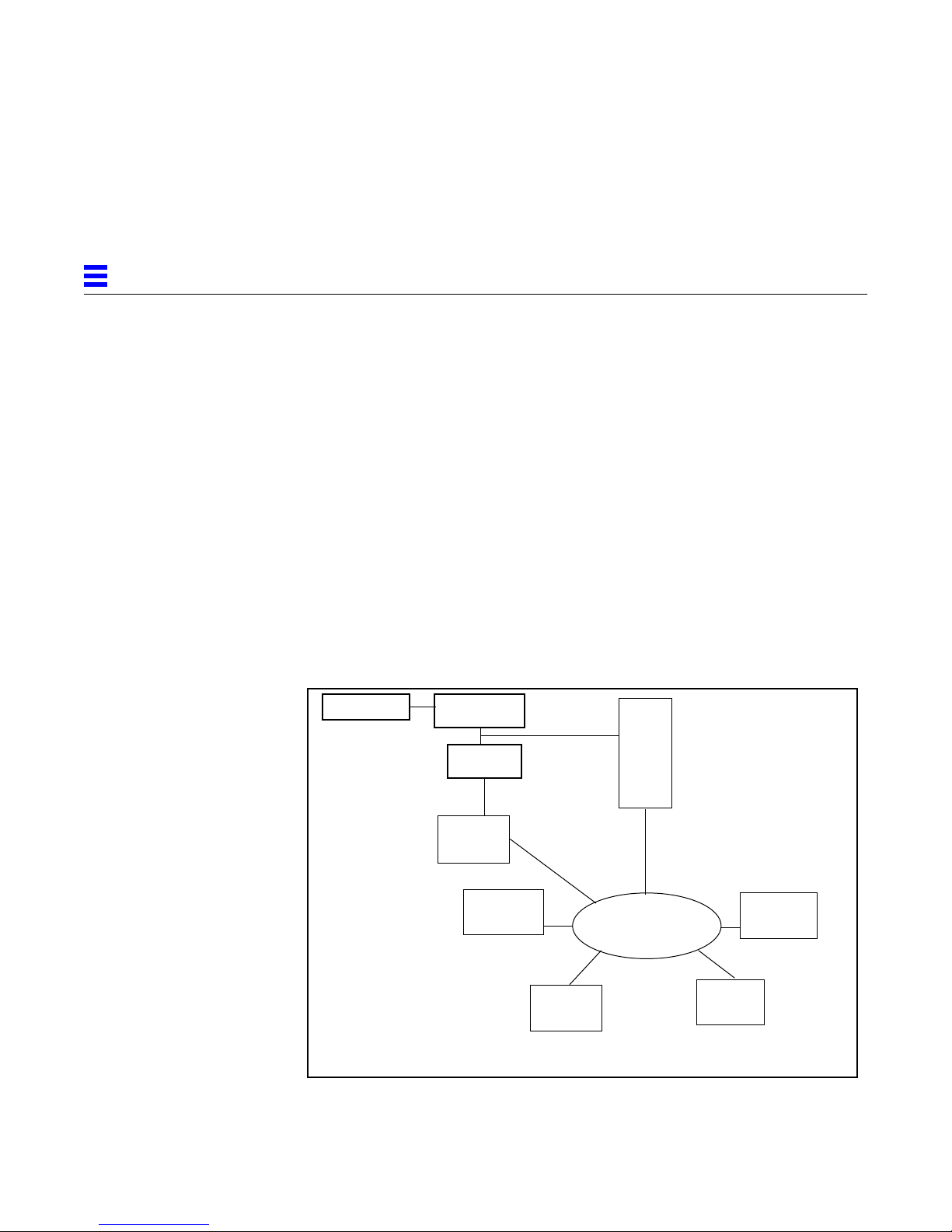
The following figure illustrates the Sun PU2.1 SNA Server in an SNA
enterprise network.
Mainframe
Figure 1-1 Sun PU2.1 SNA Server and Clients
Front End
Processor
AS/400
SNA 5250
Emulation
FTP to Host
Router Network
TCP/IP and SPX/IPX
SNA 3770
Emulation
Sun PU2.1
SNA Server
SNA LU6.2
Program
TN3270E
1-2 SunLink SNA 9.1 PU2.1 Server Configuration Guide—August 1997
Page 29

1.2 Sun PU2.1 SNA Server Components
The Sun PU2.1 SNA Server consists of several software components that
cooperate with each other to manage the distributed environment. The
following sections describe those components you will encounter most
frequently when using the server.
1.2.1 Graphical Management Interface
The Sun Graphical Management Interface (SunGMI) provides a graphical
interface for managing the Sun PU2.1 SNA Server. Using the SunGMI, you can
configure, monitor, and control the entire distributed server from a single
interface. For more information, refer to Chapter 2, “Using the Administration
Program.”
1.2.2 Gateway Manager
The Sun Gateway Manager (SunGMAN) is a network-level process that
manages the complexity of the distributed environment. The SunGMAN
maintains the configuration and status of the entire distributed server, provides
the Domain Name System (DNS) function, and supports the SunGMI.
1
To ensure that operational control is not lost and that new client connections
can be made, you can configure and run multiple instances of the SunGMAN
on multiple machines to provide a reliable manager network. If one SunGMAN
fails, the others can continue to provide service. For more information, refer to
Section 1.10, “Manager Network,” on page 1-19.
1.2.3 System Manager
The Sun System Manager (SunSMAN) is a system-level process that operates
on each system running a Sun PU2.1 server process. The SunSMAN processes
all connection requests from networked clients and performs access control.
As a Simple Network Management Protocol (SNMP) agent, the SunSMAN
responds to queries from all Sun Gateway Managers (and other SNMP
managers) and notifies these managers of system events using SNMP traps.
Since SNMP Version 2 is used as the basis for server management, security is
improved and you can use external SNMP managers, such as SunNet
Manager, HP OpenView, and NetView 6000, to manage the server.
Overview 1-3
Page 30

1
The client connection requests are directed to a system by the Sun Name
Server. For more information, refer to Section B.2, “Sun Name Server,” on
page B-3.
1.2.4 PU2.1 Server Process
The Sun PU2.1 server process (SunPU21) is the software component that
supports client connections and provides the actual data link connections to
SNA.
Each client connection requires a separate file descriptor. The number of client
connections that a PU2.1 server process can support depends on the file
descriptor limit of your operating system. For more information, refer to the
documentation for your system.
If you want a system to support more client connections than the process file
descriptor limit, you can install multiple PU2.1 server processes. You can also
install multiple PU2.1 server processes on symmetric multiprocessing (SMP)
platforms to take advantage of the multiple processors.
1.2.5 Sun Name Server
The Sun Name Server, which is part of the SunGMAN, is used with the DNS to
resolve resource requests from clients.
A client connects to the Sun PU2.1 SNA Server by specifying the name of the
resource it wants to access or by specifying its user name. If the client adds the
name of the Sun subdomain as an extension to the resource or user name, the
client instructs the local DNS to defer the resolution of the name to the Sun
Name Server. For more information about how the Sun Name Server resolves
resource requests from clients, refer to Section B.2, “Sun Name Server,” on
page B-3.
If the client requests an LU pool, the Sun Name Server performs load balancing
to direct the client to the system with the lightest load, with the highest
available bandwidth, and with available LUs. In addition, if the network is
configured appropriately, the Sun Name Server can direct the client to the
system in the most suitable geographical location. For more information, refer
to Appendix E, “Load Balancing.”
1-4 SunLink SNA 9.1 PU2.1 Server Configuration Guide—August 1997
Page 31
1.2.6 Configuration Options
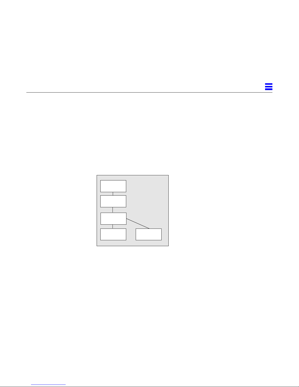
You can install the components of the Sun PU2.1 SNA Server in a variety of
ways, depending on your needs. For example, you could install all the
components on a single system. In this case, you would install one SunGMI,
one SunGMAN, and one SunSMAN. The number of SunPU21 processes would
depend on the number of client connections required. Refer to the following
figure.
System 1
SunGMI
SunGMAN
SunSMAN
1
SunPU2.1
Figure 1-2 Sample Configuration (Single System)
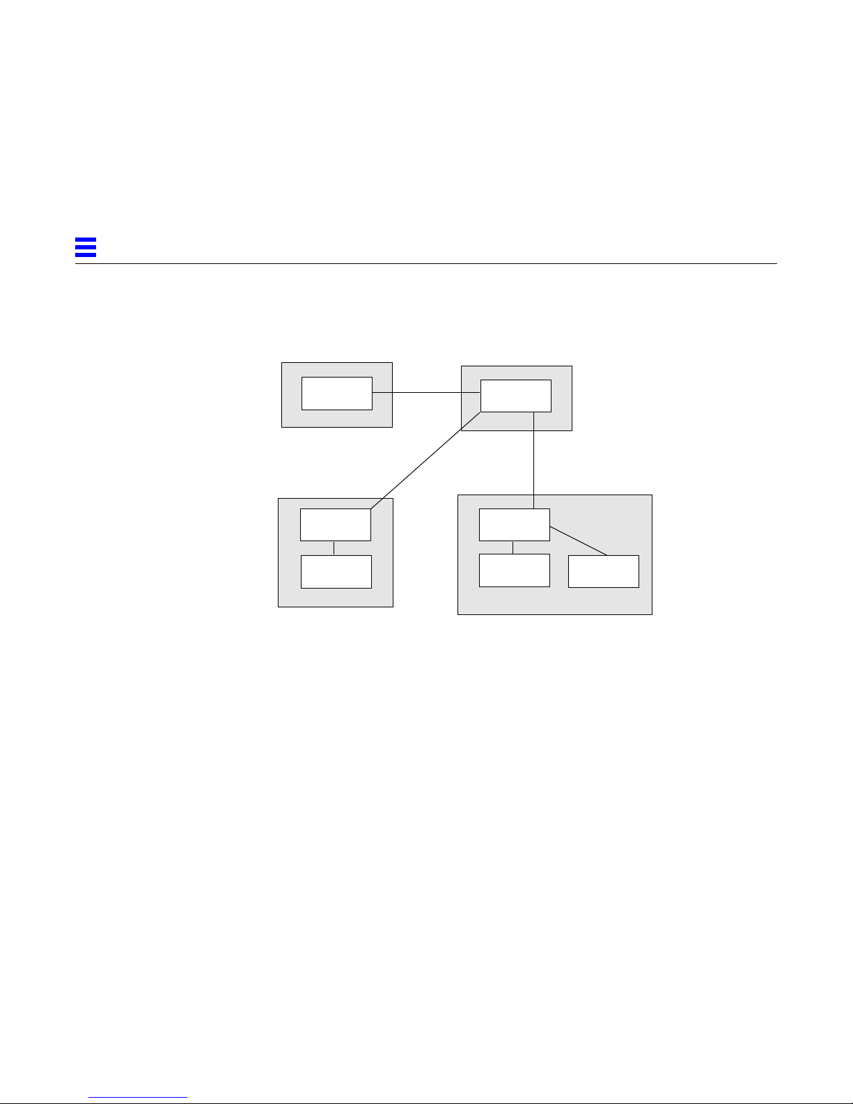
As another example, you could distribute the Sun PU2.1 SNA Server among
several systems. In this case, you could install the SunGMI on one system, the
SunGMAN on another system, and one SunSMAN on each system in the
network running a PU2.1 server process. The number of PU2.1 server processes
would depend on the number of client connections required. Refer to the
following figure.
Overview 1-5
SunPU2.1
Page 32
1
System 1
SunGMI
System 3
SunSMAN
SunPU2.1
Figure 1-3 Sample Configuration (Multiple Systems)
System 2
SunGMAN
System 4
SunSMAN
SunPU2.1
SunPU2.1
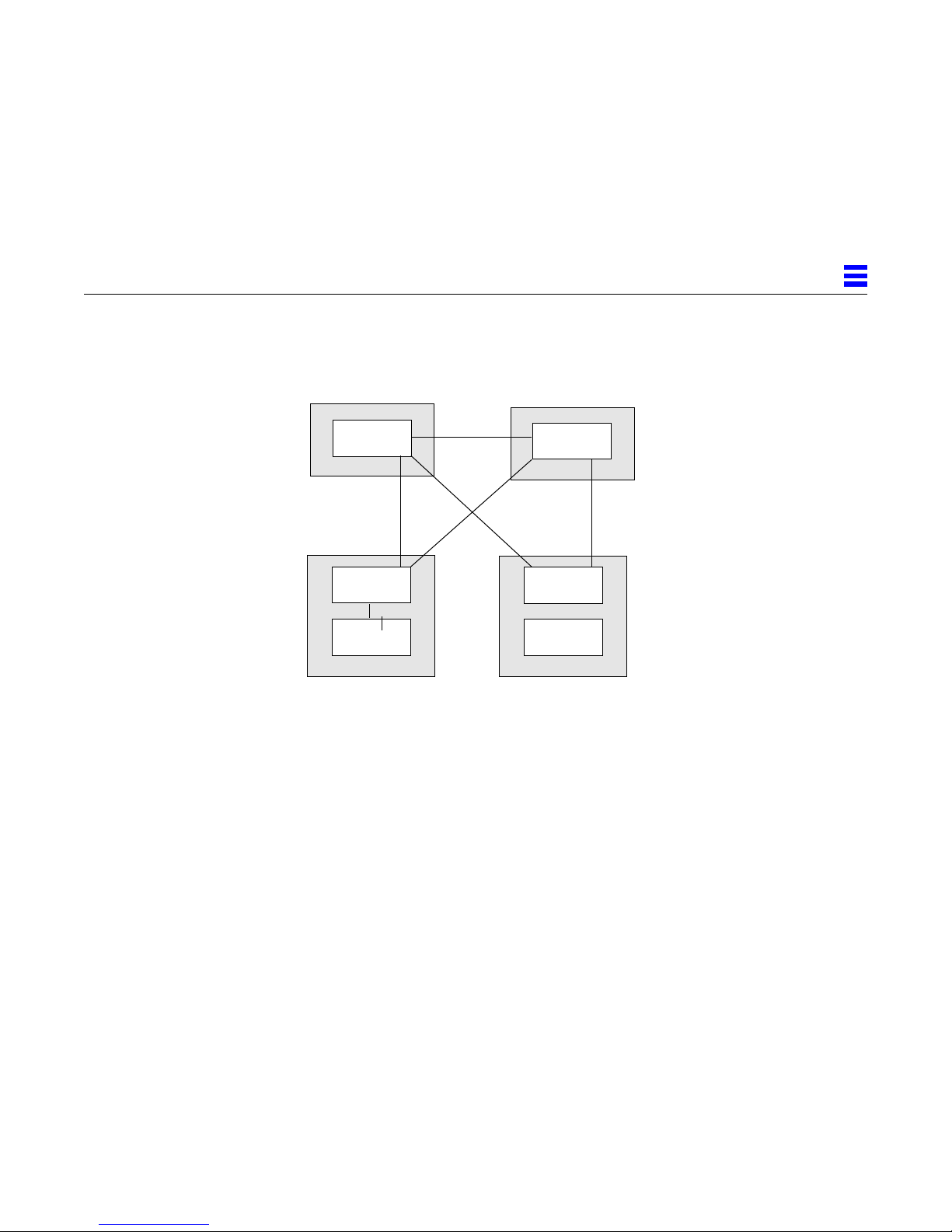
As a final example, you could create a manager network by installing multiple
instances of the SunGMAN. Refer to the following figure. For more
information about manager networks, refer to Section 1.10, “Manager
Network,” on page 1-19.
1-6 SunLink SNA 9.1 PU2.1 Server Configuration Guide—August 1997
Page 33
1
Figure 1-4 Sample Configuration (Manager Network)
1.3 Systems and Servers
The Sun PU2.1 SNA Server allows you to configure systems and PU2.1 servers.
System 1
SunGMAN
System 3
SunSMAN
SunPU2.1
System 2
SunGMAN
System 4
SunSMAN
SunPU2.1
When you configure a system, you define the machines that connect to your
SNA network and the distribution of functions among those machines. You can
add new systems at any time and bring them on-line without affecting other
systems.
When you configure a PU2.1 server, you define the SNA control point for the
local PU2.1 device, the Logical Link Control (LLC) parameters, and UNIX
security options. Each PU2.1 server supports its own data link connections.
For more information about configuring systems, refer to Chapter 4,
“Configuring Systems.” For more information about configuring PU2.1 servers,
refer to Chapter 5, “Configuring PU2.1 Servers.”
Overview 1-7
Page 34

1
1.4 Connection T ypes
1.4.1 LAN Connections
The following sections describe the connection types supported by the Sun
PU2.1 SNA Server. For more information about configuring connections, refer
to Chapter 6, “Configuring Connections.”
The Sun PU2.1 SNA Server supports IBM Token Ring (802.5), Ethernet (802.2),
and FDDI local area network (LAN) connections.
You can connect the server across a LAN in one of the following ways:
• Directly to a host with an integrated communications adapter.
• To a communications controller.
• To an IBM 3174. Note that for IBM Token Ring, the IBM 3174 must support
the Token Ring 3270 gateway feature.
LAN networking consists of two data link control sublayers, Logical Link
Control (LLC) and Medium Access Control (MAC), which control the
transmission of data across the LAN.
For IBM Token Ring, the network can have a data rate of either 4 megabits per
second (4 Mb/s) or 16 Mb/s. The networks themselves can be interconnected
by using repeaters, source routed bridges, or transparent bridges.
Note – Ethernet and FDDI connections are not supported on all platforms. For
more information, contact your Sun sales representative.
1.4.2 SDLC Connections
The Synchronous Data Link Control (SDLC) protocol controls the transmission
of data across leased lines or switched (standard dial-up telephone) lines. You
can use SDLC to connect the Sun PU2.1 SNA Server to a communications
controller or to a peer system. Other supported features include:
• Point-to-point lines (full duplex).
• Multi-point lines (half duplex).
• Primary, secondary, and negotiable station roles.
• NRZ and NRZI encoding.
1-8 SunLink SNA 9.1 PU2.1 Server Configuration Guide—August 1997
Page 35

To have an XID-3 exchange and independent LU support, you must set DLC
Role to Negotiable. Otherwise, SDLC support is PU 2.0 only.
1.4.3 QLLC Connections
You can use the Qualified Logical Link Control (QLLC) protocol to connect the
Sun PU2.1 SNA Server to an IBM communications controller over X.25 Packet
Switched Data Networks (PSDNs) by using X.25 virtual circuits (VCs). Both
Permanent Virtual Circuits (PVCs) and dial-in and dial-out Switched Virtual
Circuits (SVCs) are supported.
The communications controller runs the IBM NCP Packet Switched Interface
(NPSI) program (Version 2/Release 1 or higher) and uses the QLLC protocol to
control the transmission of data across the VC.
QLLC connections support packet and window size negotiation and point-topoint lines.
Although multi-point lines are not supported, multiple QLLC connections can
be supported over a single link over the X.25 PSDN.
1
1.5 PU2.1 Emulation
Note – The QLLC protocol only supports PU 2.0.
When operating in traditional hierarchical SNA networks, the Sun PU2.1 SNA
Server emulates a PU2/PU2.1 device, such as a 3274 cluster controller or a 3174
establishment controller.
When operating in peer-to-peer SNA networks, the Sun PU2.1 SNA Server
uses Advanced Peer-to-Peer Networking (APPN) or Low Entry Networking
(LEN) to connect to a PU2.1 peer system, such as AS/400 and System/36. The
server supports traditional display emulation and hierarchical connectivity and
peer-to-peer connectivity using the SNA LUType 6.2 protocols.
The number of physical units you can configure depends on the connection
type, as follows:
• IBM Token Ring, Ethernet, and FDDI LAN connections - You can
configure multiple PUs for each Service Access Point (SAP) and multiple
SAPs for each network interface controller.
Overview 1-9
Page 36

1
1.6 LU Emulation
• SDLC and QLLC connections - For point-to-point lines, you can configure
one PU for each line. For multi-point lines, you can configure multiple PUs
for each line.
• Channel connections - You can configure multiple PUs on the channel. Each
PU uses a separate subchannel address.
A PU2/PU2.1 emulated by the Sun PU2.1 SNA Server is activated by the IBM
mainframe Virtual Telecommunications Access Method (VTAM). VTAM
establishes a System Services Control Point (SSCP)-to-PU control session with
each PU2/PU2.1 during activation. The server maintains the SSCP-PU control
session and opens an interface to allow client programs to access it.
For more information about configuring PUs, refer to Chapter 7, “Configuring
PUs.”
The Sun PU2.1 SNA Server supports both dependent LUs and independent
LUs, as follows:
• Dependent LUs - Each PU2.1 device can support the following types of
dependent LU: LUType 0, LUType 1, LUType 2, LUType 3, and LUType 6.2.
VTAM activates the dependent LUs, which rely on the SSCP-PU control
session for activation and session initiation. During activation, the IBM
mainframe establishes an SSCP-LU control session with each activated
dependent LU. The server maintains the SSCP-LU control session and opens
an interface to allow client programs to access it.
The server assists in the establishment of dependent LU-LU sessions. An
IBM mainframe application (primary LU) asks to bind with a client program
(secondary LU). If a client program is present at the LU, the server
establishes an SNA session.
You can group dependent LUs into LU pools to control access to the
dependent LUs. For more information, refer to the following section.
• Independent LUs - Independent LUs are activated locally either through
auto-activation or through operator control. Independent LUs can be
LUType 6.2 only.
1-10 SunLink SNA 9.1 PU2.1 Server Configuration Guide—August 1997
Page 37

1.7 LU Pools
1
For independent LU-LU sessions, either independent LU can initiate the
session. In addition, multiple sessions, known as parallel sessions, can be
established between two independent LUs.
For both SSCP-LU control sessions and LU-LU application sessions, the Sun
PU2.1 SNA Server enforces the SNA protocols.
For more information about configuring dependent LUs, refer to Chapter 8,
“Configuring Dependent LUs.” For more information about configuring
independent LUs, refer to Chapter 9, “Configuring for LUType 6.2.”
LU pools are groups of dependent LUs that are accessible to certain users. If a
user specifies an LU pool name instead of an LU name, the Sun PU2.1 SNA
Server assigns the user to one of the dependent LUs in the LU pool. All
dependent LUs in a particular LU pool must be of the same type (all LUType
0, all LUType 1, all LUType 2, all LUType 3, or all LUType 6.2).
Although you can assign any type of dependent LU to an LU pool, LU pools
are most commonly used for LUType 2 dependent LUs for access by 3270
clients.
You can provide redundancy by distributing an LU pool across multiple
systems. If some of the systems are removed from operation, the remaining
systems can still accept new client connections.
If the LU pool is distributed across multiple systems, the server uses load
balancing to direct the client to the system with the lightest load, with the
highest available bandwidth, and with available LUs. In addition, if the
network is configured appropriately, the server can direct the client to the
system in the most suitable geographical location. For more information, refer
to Appendix E, “Load Balancing.”
LU pools are also useful for the following:
• You can simplify user access by providing all users with a single LU pool
name, instead of providing each user with a separate dependent LU name.
Users are isolated from configuration changes.
• You can maximize the use of host resources by defining only enough host
dependent LUs to meet your peak usage. Note, however, that defining
additional resources ensures adequate availability if a system or connection
fails.
Overview 1-11
Page 38

1
• A group of intermittent users can use limited resources more efficiently. For
example, if 15 users need only intermittent access to five dependent LUs,
you can create an LU pool for these users.
• By selecting an LU pool, a client or group of clients can ensure that
connections are limited to a known set of dependent LUs.
• If you want to limit a group of users to a single host and the host is
connected to a particular PU2.1 server, creating an LU pool ensures that any
client software started by these users connects to the correct host.
• Providing an LU pool separates the resources from the client, allowing
changes to the server without requiring changes to the client configuration.
For more information about creating an LU pool, refer to Section 8.4, “Creating
an LU Pool,” on page 8-9.
1.8 Users and User Groups
The Sun PU2.1 SNA Server allows you to create user records for clients and for
system/network administrators. You can also use a wild-carded fully-qualified
domain name or a masked IP address to specify a group of users (clients or
system/network administrators) that have common requirements without
specifying each user individually.
User records allow you to control the resources to which a client can connect.
You define a list of preferred and alternate default resources in the user record.
If the client does not (or cannot) specify a resource when connecting to the
host, the server tries to connect the client to the preferred default resource. If
the preferred resource is not available, the server sequentially checks the
alternate resources until it finds an available LU. If your LUs are
geographically dispersed, you can use multiple default resources to ensure that
LUs closest to the client are checked first.
You can specify one or more of the following default resources for each client:
• Dependent LU or independent LU - Allows you to provide a single known
LU for the client connection. In case of problems, you can determine which
LU the client was connected to. For a dependent LU, you can add this user
record to the access list of the LU to restrict the LU to that client connection.
Note – If you use an LU as the default resource and a system or network
outage occurs, the client may not be connected since the LU is not available.
1-12 SunLink SNA 9.1 PU2.1 Server Configuration Guide—August 1997
Page 39

1
• LU pool - Allows you to maximize access to the host system. A client does
not depend on a system or a connection to access the host system, but can
connect to a dependent LU as long as the LU is available from the pool.
• PU - Allows you to provide several resources for the client connection. If a
particular dependent LU is unavailable or in use, the client can connect to
another LU under the PU. In addition, multiple users from a node can
access the host system.
Note – If you use a PU as the default resource and a system outage occurs,
local area users may not have host connections since the PU is not available.
Note – If you use multiple default resources, Sun recommends that you do not
specify a PU in the list.
For an LUType 2 client, if you do not specify a default resource or if none of
the default resources exist, and if the client does not specify a resource, the
server connects the client to the LU pool PUBLIC. For an LUType 0, LUType 1,
LUType 3, or LUType 6.2 client, if you do not specify a default resource or if
none of the default resources exist, and if the client does not specify a resource,
the software returns an error.
Note that you can also specify the users or user groups that can access a
resource (dependent LU or LU pool) in the configuration of the resource. This
allows you to make changes to a user record without modifying the resource.
Note that if no users or user groups are specified for a resource, any client can
access the resource.
User records also allow you to specify which resources system/network
administrators can configure and control. By default, all system/network
administrators are master operators. As a master operator, you can modify the
configuration of the server or change the status of resources without
restriction. You can also create user records to restrict the access of other
system/network administrators to a particular portion of the active
configuration, enabling you to establish independent operator domains.
Note – You can add, modify, or delete users at any time without affecting
existing sessions.
Overview 1-13
Page 40

1
1.9 Supported Clients
For more information about configuring users and user groups, refer to
Chapter 10, “Configuring Users.”
Client programs access SNA sessions through ports provided by the Sun PU2.1
SNA Server. The server provides the following services for client programs:
• SNA protocol enforcement.
• Lower-level SNA protocol support.
• Host notification of special events. If no client program is registered for a
dependent LU port, the server notifies the IBM mainframe that the
dependent LU is powered-off. If a client program registers for a dependent
LU port, the server notifies the IBM mainframe that the dependent LU is
powered-on.
The following sections describe the clients supported by the Sun PU2.1 SNA
Server. For more information, refer to your client documentation.
In addition, contact your Sun sales representative for information about thirdparty software products that use the communications services of the Sun PU2.1
SNA Server. These third-party software products include on-line transaction
programs, data movement utilities, and distributed databases.
Note – No special client software is required to access the Sun PU2.1 SNA
Server.
1.9.1 Traditional Telnet 3270
Traditional Telnet 3270 (TN3270) is the standard method for connecting 3270
terminal emulators to IBM mainframes over TCP/IP networks. The Sun PU2.1
SNA Server, which includes a Telnet 3270 server, allows TN3270 clients to
connect to an IBM mainframe by using the SNA protocol. You do not have to
run TCP/IP on your mainframe.
You can configure LUs for traditional TN3270 clients as either terminals or
printers. Typically, use LU pools for assignment of terminal clients and use
specific LU assignment for printer clients.
1-14 SunLink SNA 9.1 PU2.1 Server Configuration Guide—August 1997
Page 41

Because a traditional TN3270 client cannot specify a resource to connect to, the
Sun PU2.1 SNA Server allows you to define a user record for the client. The
user record includes either an IP address or an IP hostname to identify the
client and one or more default resources to be used by the client. The server
looks for a user record with either an IP address or IP hostname that matches
the IP address or IP hostname of the client and assigns one of the default
resources defined in the user record to the client at connection time. The
default resource can be an LU, a PU, or an LU pool. For more information
about configuring a user record, refer to Chapter 10, “Configuring Users.”
The Sun PU2.1 SNA Server supports NetView Response Time Monitoring
(RTM) for traditional TN3270 clients. For more information about initiating the
measurement of RTM statistics, refer to Section 12.1.1.4, “Using the RTM
Table,” on page 12-14.
1.9.2 Extended Telnet 3270E
Extended TN3270E (RFC 1646 and RFC 1647) provides the features of
traditional TN3270 as well as the following:
• TN3287 printer support.
• Associated printer support. You can associate a printer LU with a TN3270
terminal LU. This allows the user to configure the terminal and printer
emulators by knowing only the terminal LU name. At connection time, the
printer emulator requests the LU associated with the terminal, provides the
terminal LU name, and is connected to the correct printer LU.
• LUType 1 and LUType 3 printer support. You can use printers for either
SNA Character Stream (SCS) or 3270 Data Stream (DS) style printing.
• Access to SNA bind image and unbind notification.
• Support for ATTN and SYSREQ keys. The ATTN key causes an interrupt to
the application (Signal RU). The SYSREQ key provides access to SSCP-LU
sessions.
• Support for positive or negative SNA response handling by the client
software.
• Support for device pools. You can group terminals or printers into pools to
satisfy generic or specific resource requests.
1
Extended TN3270E clients can specify a resource (either an LU or an LU pool)
when connecting to the host. In addition, the Sun PU2.1 SNA Server allows
you to define a user record for an extended TN3270E client. The user record
Overview 1-15
Page 42

1
can contain one or more default resources to be used by the client when none
is specified in the connection request. For more information about configuring
a user record, refer to Chapter 10, “Configuring Users.”
1.9.3 Sun 3270
Sun 3270 (Sun3270) uses the LUType 2 interface to connect Sun 3270 terminal
emulators to IBM mainframes. Sun3270 provides the features of traditional
TN3270, the features of extended TN3270E, and additional features, such as the
exchange of keep-alive information.
Sun3270 clients can specify a resource (either an LU, an LU pool, or a PU/LU
local address pair) when connecting to the host. In addition, the Sun PU2.1
SNA Server allows you to define a user record for a Sun3270 client. The user
record can contain one or more default resources to be used by the client when
none is specified in the connection request. For more information about
configuring a user record, refer to Chapter 10, “Configuring Users.”
Sun3270 uses TN3270E to access SNA hosts. It emulates 3278 (models 2
through 5), 3279, and 3279G display stations, and 3287 printers. EHLLAPI,
IND$FILE file transfer, and GDDM are also supported.
1.9.4 Sun 3770/RJE
Sun 3770 (Sun3770) is an SNA 3770 emulator for an IBM 3776 workstation
device. It is used for Remote Job Entry (RJE) and batch file transfer over SNA
networks.
Sun3770 clients can specify a resource (either a PU, an LU, or an LU pool)
when connecting to the host. Since a Sun3770 client represents an RJE station
and can connect to multiple LUs, LU pools ensure that specific LUs are
assigned to a Sun3770 client at connection time. You can also define a user
record for the Sun3770 client and then specify the LU pool as the default
resource. For more information about creating an LU pool, refer to Section 8.4,
“Creating an LU Pool,” on page 8-9. For more information about configuring a
user record, refer to Chapter 10, “Configuring Users.”
1-16 SunLink SNA 9.1 PU2.1 Server Configuration Guide—August 1997
Page 43

1.9.5 Sun APPC
Advanced Program-to-Program Communication (APPC) allows programs on
peer systems to communicate with each other over an SNA network. Sun
APPC (SUNWappc) allows you use the SunLU6.2 Transaction Programmer's
Reference verbs or the Common Programming Interface for Communications
(CPI-C) calls to write APPC transaction programs (TPs) to interact with both
IBM mainframe and SNA peer applications. For more information, refer to the
SunLU6.2 Transaction Programmer ’s Reference and SunLU6.2 CPI-C
documentation listed in “Related Sun Documents” in the Preface.
For SunAPPC clients, you must configure the following:
• Local independent LU or local dependent LU. For information on
configuring an independent LU, refer to Section 9.1, “Configuring an
Independent LU,” on page 9-2. For information on configuring a dependent
LU, refer to Chapter 8, “Configuring Dependent LUs.”
• Partner LU for the local LU. For more information, refer to Section 9.2,
“Configuring a Partner LU,” on page 9-4.
• Session mode for the LU-LU pair. For more information, refer to Section 9.3,
“Configuring the Session Mode,” on page 9-7.
• LU6.2 users that can access the local LU. For more information, refer to
Section 9.4, “Configuring an LUType 6.2 User,” on page 9-12.
• Invocable TPs that are accessed by the local LU and the control operator TPs
that require special privileges. For more information, refer to Section 9.5,
“Configuring a Transaction Program,” on page 9-13.
1
Note – You can configure a TP for a specific local LU (Type 6.2) or for all local
LUs (Type 6.2). In addition, SNA service transaction programs, such as Change
Number of Sessions (CNOS), do not require a TP definition since they are
automatically defined.
If your Sun PU2.1 SNA Server is installed on multiple systems, you can
configure APPC on more than one of the systems. A networked TP can locate
the server it requires by using the Sun Name Server. The Sun Name Server
resolves requests for LU names to the system on which the local LU is
configured. For more information, refer to Section B.4, “Using the Sun Name
Server with APPC,” on page B-7.
Overview 1-17
Page 44

1
1.9.6 Telnet 5250 and Sun 5250
Telnet 5250 (TN5250) is the standard method for connecting 5250 display
system emulators to IBM midrange systems, such as AS/400, System/36, and
System/38, over TCP/IP networks. Sun 5250 (Sun5250) connects to the host
system by using TN5250 protocols.
For TN5250 and Sun5250 clients, you must configure the following:
• Local independent LU. For more information, refer to Section 9.1,
“Configuring an Independent LU,” on page 9-2.
• Partner LU for the local LU. For more information, refer to Section 9.2,
“Configuring a Partner LU,” on page 9-4.
• Session mode for the LU-LU pair. For more information, refer to Section 9.3,
“Configuring the Session Mode,” on page 9-7.
Note – Before you configure resources for TN5250 and Sun5250 clients, Sun
recommends that you consult with your AS/400 system programmer to
coordinate the AS/400 and Sun configurations.
1.9.7 File Transfer Protocol
The Sun PU2.1 SNA Server includes a file transfer protocol (FTP) that converts
TCP/IP file transfers into SNA file transfers. This allows a TCP/IP FTP client
to get files from and put files on any IBM mainframe or midrange system that
supports AFTP (APPC File Transfer Protocol) communications, without
running TCP/IP on the system. AFTP is available on all IBM SAA platforms
and is included in VTAM 4.2. Earlier versions of VTAM support AFTP as a
licensed product.
Note that you can configure the Sun AFTP server to run on one or more
systems.
For FTP clients, you must configure the following:
• Local independent LU or local dependent LU. For information on
configuring an independent LU, refer to Section 9.1, “Configuring an
Independent LU,” on page 9-2. For information on configuring a dependent
LU, refer to Chapter 8, “Configuring Dependent LUs.”
• Partner LU for the local LU. For more information, refer to Section 9.2,
“Configuring a Partner LU,” on page 9-4.
1-18 SunLink SNA 9.1 PU2.1 Server Configuration Guide—August 1997
Page 45

• Session mode for the LU-LU pair. For more information, refer to Section 9.3,
“Configuring the Session Mode,” on page 9-7.
• LU6.2 users that can access the local LU. For more information, refer to
Section 9.4, “Configuring an LUType 6.2 User,” on page 9-12.
• Invocable TPs that are accessed by the local LU and the control operator TPs
that require special privileges. For more information, refer to Section 9.5,
“Configuring a Transaction Program,” on page 9-13.
• Note that you can configure a TP for a specific local LU (Type 6.2) or for all
local LUs (Type 6.2). In addition, SNA service transaction programs, such as
Change Number of Sessions (CNOS), do not require a TP definition since
they are automatically defined.
1.9.8 Other Sun SNA Clients
The Sun PU2.1 SNA Server also provides the TCP/IP-to-SNA gateway function
for the following Sun SNA clients:
• SunLU0 API - A series of library routines that allow you to write programs
that interact with IBM mainframe applications over TCP/IP. Your programs
have complete access to the SNA Request Headers and Request Units and
can use both LU-LU and SSCP-LU sessions.
• SunNMI API - A series of library routines that allow you to write programs
to interact with network management programs, such as NetView, residing
on the IBM mainframe. This API facilitates communication over SSCP-PU
control sessions.
• SunSNM - Captures events generated by SunNet Manager and reports
these events as SNA alerts to IBM NetView for logging and analysis.
SunSNM also allows NetView operators to issue RUNCMDs for execution
on remote UNIX systems. SunSNM is available on Sun SPARC-based
systems only.
1
1.10 Manager Network
To ensure the reliability of your system and protect against system failure, you
can create multiple instances of the SunGMAN and include them in a manager
network. Each instance of the SunGMAN is referred to as a manager system. If
one manager system fails, the Sun PU2.1 SNA Server continues to function.
Overview 1-19
Page 46

1
Each manager system automatically sets up a connection to each of the other
manager systems. When more than 50% of the manager systems are in contact
with each other, a quorum is established and the software automatically selects
one of the manager systems to be the primary manager system. The other
manager systems are secondary manager systems. When you connect to the
Sun PU2.1 SNA Server from the SunGMI, the Sun Name Server routes your
connection to the primary manager.
Only the primary manager system can make changes to configurations. When
you make a configuration change and save it, the primary manager system
updates the configuration database and distributes the updated configuration
to all the other manager systems in the network using a 2-phase commit
protocol. Since the complete configuration is replicated on each manager
system, data is not lost if a manager system fails, and service is not interrupted
while a backup is restored.
Both the primary manager system and the secondary manager systems can
update the status of resources, distribute event information, handle DNS
requests and return the IP addresses of the system where the specified
resource can be found, and perform load balancing. If a manager system is
located in each physical site, requests for resource location and load balancing
can be handled by the local manager system, reducing the time delay for client
requests.
If a manager system loses contact with the others, the manager network
continues to operate provided that a quorum is maintained among the
remaining manager systems. This prevents two (or more) disconnected
fragments of the manager network from attempting to manage the Sun PU2.1
SNA Server at the same time. If a quorum cannot be established, configuration
capability is disabled and only DNS requests can be performed. This
guarantees that the distributed database is correct at all times.
If the primary manager system fails and the remaining manager systems can
establish a quorum, a new primary manager system is elected. The primary
manager system is the manager system with the most up-to-date configuration.
If a manager system rejoins the manager network or if a new manager system
is created and added to the manager network, that manager system receives
the latest configuration from the primary manager system.
For more information on creating manager systems, refer to Section 11.3.2,
“Adding a Manager System,” on page 11-9.
1-20 SunLink SNA 9.1 PU2.1 Server Configuration Guide—August 1997
Page 47

1.1 1 Peer-to-Peer Operations
The Sun PU2.1 SNA Server supports peer-to-peer operations between a PU2.1
device and either a PU4 or PU5 device or another PU2.1 device, as follows:
• PU4 or PU5 device - The physical connection between the PU2.1 device and
a PU4 or PU5 device, such as a 3745 communications controller or an
ES/9000 mainframe, can be through any of the supported connection types.
For more information, refer to Section 1.4, “Connection Types,” on page 1-8.
For SDLC and QLLC connections, the local link station can assume a
primary, secondary, or negotiable role. Note that in traditional SNA
networks, only the secondary role is supported.
PU2.1 devices connect directly to VTAM in a PU5 device.
When using the Network Control Program (NCP), peripheral node Type2.1
support is included in Version 4, Release 3. You do not have to define the
traditional NCP parameters, such as DATMODE, MAXDATA, MAXOUT, MODULO,
and PASSLIM, since this information is conveyed on the XID. You should,
however, set PUTYPE=2 and XID=YES in the NCP PU macro definition.
• PU2.1 device - No host configuration is necessary. Information about the
device configuration is conveyed between the two devices, using their XID
exchange. The XID contains information about station identification, role,
modulo, outstanding frames, and maximum frame size.
1
The Sun PU2.1 SNA Server includes the SunLU6.2 security utility, which
provides both LU6.2-based security and UNIX-based security for peer-to-peer
operations.
For each local LUType 6.2, you can define a list of remote LUType 6.2 users
who are allowed to run TPs on the LU. In addition, you can define a list of
users who are allowed to run TPs on any local LU. When conversation-level
security is required, access security parameters in incoming Attach requests are
verified against this LUType 6.2 user information. If the Sun PU2.1 SNA Server
is configured to perform UNIX-level security, you do not have to specify
LUType 6.2 user passwords because users are verified with UNIX password
security. You can restrict TP access to a subset of the defined LUType 6.2 users.
For more information, refer to Appendix G, “LUType 6.2 Security.”
Overview 1-21
Page 48

1
1-22 SunLink SNA 9.1 PU2.1 Server Configuration Guide—August 1997
Page 49

Using the Administration Program
This chapter contains the following sections:
• Starting the SNA Server Administration Program - describes how to start
the Sun Graphical Management Interface (sungmi).
• Using the Main Window - describes the components of the main window.
• Using Sub-Windows - describes the sub-windows that the SunGMI
supports.
• Managing Windows - describes how to manage windows.
• Selecting Items - describes how to select items in a window.
• Initiating Actions - describes how to initiate actions from the SunGMI.
• Using Dialog Boxes - describes how to use the dialog boxes provided by the
SunGMI.
2.1 Starting the Graphical Management Interface
The Sun Graphical Management Interface (SunGMI) allows you to perform
administrative tasks on the Sun PU2.1 SNA Server. To start the SunGMI,
execute the following command:
sungmi [X options] [-p password] domain &
2
where
sungmi is the name of the command.
X options are any standard X options (see X(1) for details).
2-1
Page 50
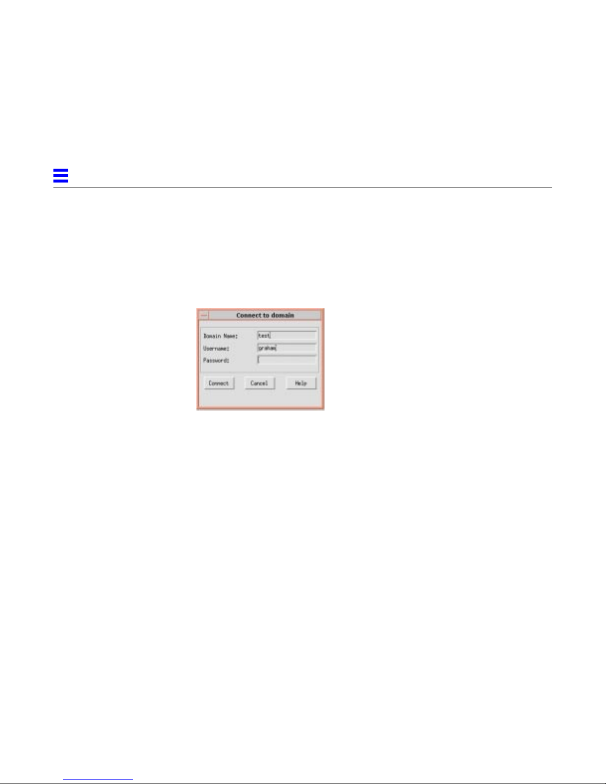
2
password specifies the password to use when connecting to the Sun PU2.1 SNA
Server.
domain is the name of the Domain Name System (DNS) domain implemented
by the Sun PU2.1 SNA Server.
If you do not specify a domain name, the software displays the Connect to
:
domain dialog box.
2-2 SunLink SNA 9.1 PU2.1 Server Configuration Guide—August 1997
Page 51

To specify a domain name:
Domain Name
Username
Password
2
1. Enter the following information:
The DNS domain implemented by the Sun PU2.1 SNA Server. Note that if you
enter the IP hostname or address of a system running the server, you may not
connect to the primary server.
The operator user name you want to connect as. The default is your Unix user
ID. If a user record with Operator privileges is defined, this Username must
match the User ID field of the user record. If a user record with Operator
privileges is not defined, any name is valid.
The password to use when connecting. If a password is defined in a user
record, this Password must match the Password field of the user record. If not,
this Password is ignored.
2. Click Connect (or press the Enter key) to initiate the connection to the
server.
Click Cancel to abandon the connection attempt. Note that if you abandon
the connection attempt, the only actions you can perform are connecting to
the domain and exiting from the server.
After you connect to the domain, the software displays the main window. For
more information about the main window, refer to the next section.
2.2 Using the Main Window
The following figure illustrates the main window.
Using the Administration Program 2-3
Click Help to display more information about the dialog box.
Page 52
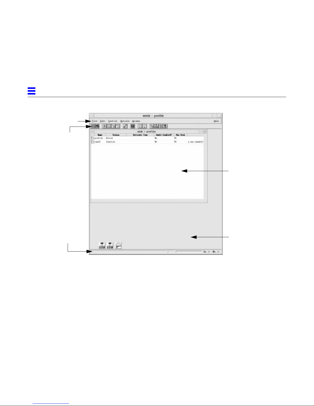
2
Menu bar
Toolbar
Sub-window
Status line
Client area
The components of the main window are described as follows:
• Menu bar - Includes menu commands for performing all actions. The menus
that are available at a particular time and the commands that are available
from a particular menu depend on the currently selected window and
resource. For more information about menus, refer to Section 2.6.2, “Menu
Commands,” on page 2-12.
• Toolbar - Contains buttons that provide shortcuts for performing menu
actions. Buttons are enabled only if their actions are available at the current
time for the currently selected resource. For more information about the
toolbar buttons, refer to Section 2.6.1, “Toolbar Buttons,” on page 2-11.
• Client area - The large central area used to display sub-windows.
• Status line - The line at the bottom of the main window. The left-most area
is a text area used to display descriptions of menu and toolbar items and
error and progress messages. The middle area is the progress meter, which
displays the progress of operations in both text and bar form. Whenever the
SunGMI is communicating with the Sun Gateway Manager (SunGMAN),
2-4 SunLink SNA 9.1 PU2.1 Server Configuration Guide—August 1997
Page 53

the progress bar displays a blue bar that moves back and forth. The rightmost area indicates when messages are being sent to (Tx) and received from
(Rx) the SunGMAN.
• Sub-window - A window that contains domain or resource information. For
information about the supported sub-windows, refer to the following
section.
2.3 Using Sub-Windows
The Sun PU2.1 SNA Server supports the following sub-windows, which are
described in the following sections:
• Configuration window
• Managers window
• Applications window
• Licenses window
• Traces window
• Events window
• Resource window
2
2.3.1 Configuration Window
The configuration window displays a list of the configurations that currently
exist. The title bar contains the name of the domain that contains the
configurations.
When you start the SunGMI, the configuration window is displayed in the
client area. Note that if <None> is displayed in the configuration window, either
you are not connected to the primary manager or no primary manager exists.
Using the Administration Program 2-5
Page 54
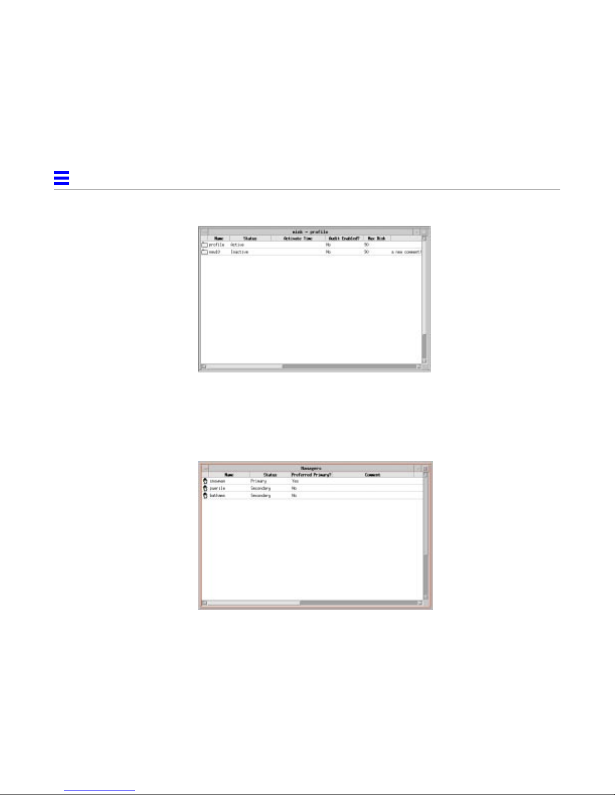
2
2.3.2 Managers Window
The Managers window displays a list of the manager systems included in the
manager network (the systems that are currently running the SunGMAN).
Select Window → Managers List to display the Managers window.
2.3.3 Applications Window
The Applications window displays a list of application programs currently
connected to the Sun PU2.1 SNA Server. The list includes all instances of the
SunGMI that are connected. Select Window → Application List to display the
Applications window.
2-6 SunLink SNA 9.1 PU2.1 Server Configuration Guide—August 1997
Page 55
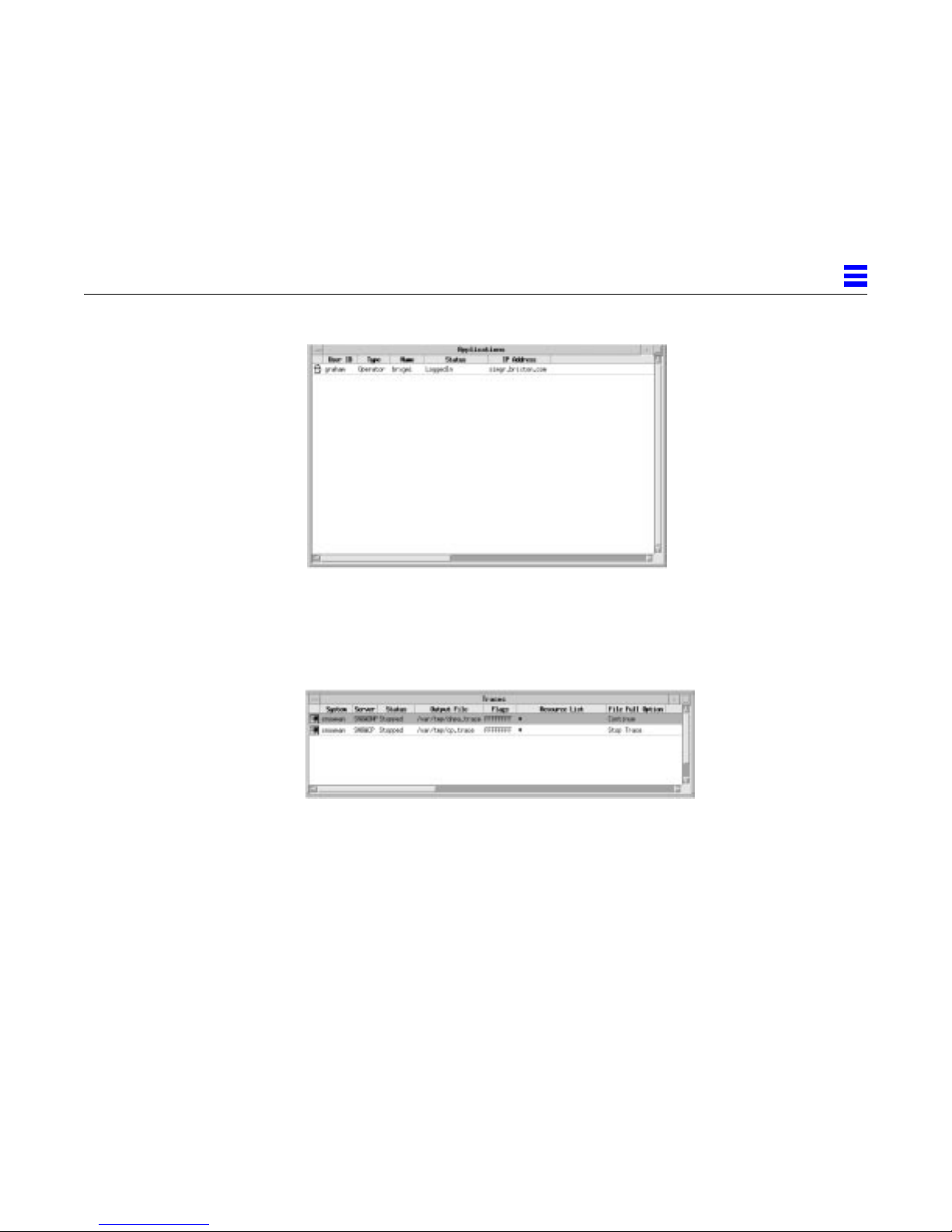
2.3.4 Traces Window
The Traces window displays information about traces currently in effect. Select
Window → Active Traces List to display the Traces window.
2
2.3.5 Events Window
The Events window displays event information about the current domain.
Select Window → Event Log to display the Events window.
Using the Administration Program 2-7
Page 56
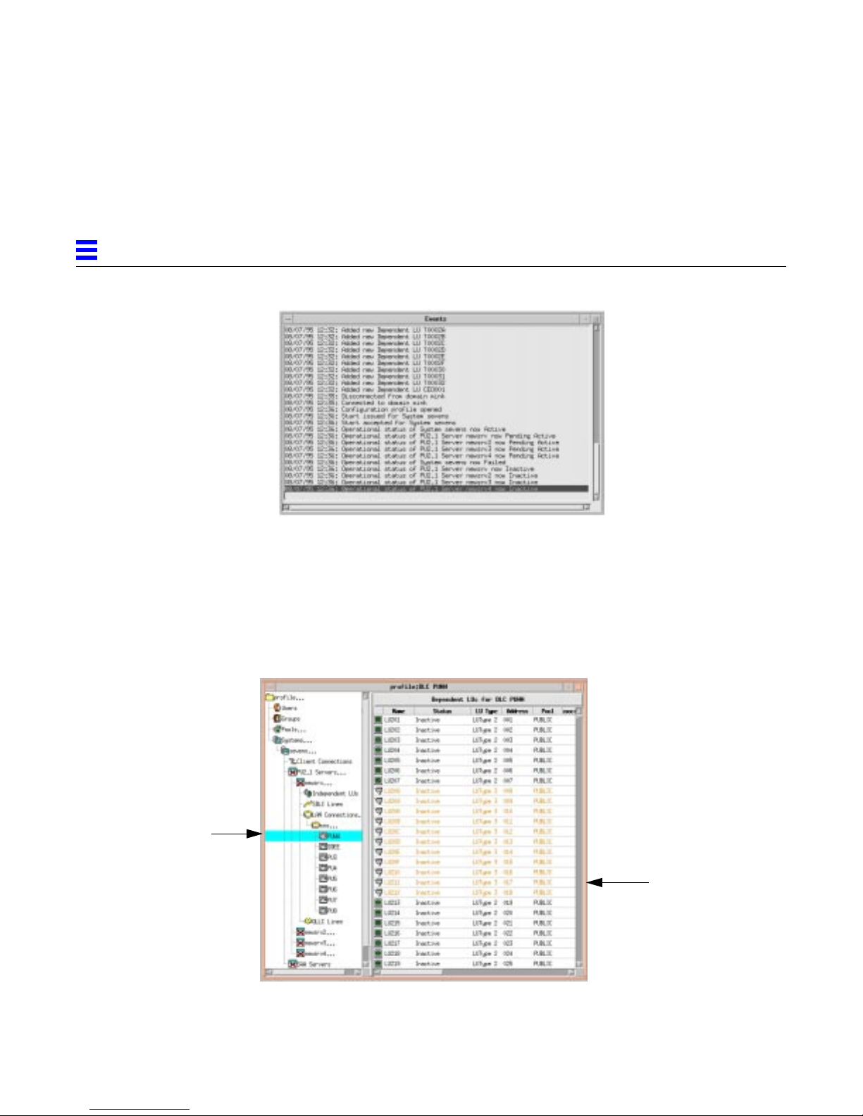
2
2.3.6 Resource Window
The resource window displays all of the resources in the current configuration.
To display the resource window for a configuration, double-click the
configuration in the configuration window. The title bar of the resource
window contains the configuration name and the current position in the
hierarchy.
Resource
tree
2-8 SunLink SNA 9.1 PU2.1 Server Configuration Guide—August 1997
Resource
table
Page 57
The resource window contains the following areas:
• Resource tree - The left area of the resource window contains the resource
tree, which shows a tree representation of the complete contents of the
configuration. To expand or contract elements in the tree, either double-click
the element with the left mouse button (MB1) or click and hold the right
mouse button (MB3) and then select Expand Entry or Contract Entry from
the popup menu.
• Resource table - For the highlighted element in the resource tree, the right
area of the resource window contains the resource table, which is a list of
resources. The resources listed depend on the element selected in the
resource tree. For example, if the Systems icon is selected, the resource table
displays a list of systems.
2.4 Managing Windows
The following table describes the tasks you can perform to manage windows.
Table 2-1 Window Management Tasks
Task Action
2
Shrink a window to an icon. Click the small button icon in the window’s
upper right corner, or click the button in
the upper left corner of the window and
then select Minimize.
Small button icon
Maximize a window. Click the large button icon in the window’s
upper right corner, or click the button in
the upper left corner of the window and
then select Maximize.
Large button icon
Restore a window from an icon. Double-click the icon, or select the window
from the Window menu.
Using the Administration Program 2-9
Page 58

2
Table 2-1 Window Management Tasks
Task Action
Restore a maximized window to its
original size.
Close a window. Click the button in the upper left corner of
Click the inverted large button icon in the
window’s upper right corner, or click the
button in the upper left corner of the
window and then select Restore.
the window and then select Close.
2.5 Selecting Items
2.6 Initiating Actions
Arrange all open windows edge-byedge.
Arrange all open windows in an
overlapping display.
To select a single item in a sub-window or in a resource table, click the item.
You can select multiple adjacent items in one of the following ways:
Select Window → Tile.
Select Window → Cascade.
• Place the mouse pointer on one of the items, click and hold the left mouse
button (MB1), and drag the mouse pointer up or down.
• Select the first item, scroll down the window until the last object is
displayed, and press Shift-MB1.
• Click and hold the right mouse button (MB3) and select Select All from the
popup menu.
You can initiate an action in one of the following ways:
• Click a button on the toolbar. For more information, refer to the following
section.
• Select a menu command. For more information, refer to Section 2.6.2, “Menu
Commands,” on page 2-12.
• Position the mouse pointer on the appropriate resource, click and hold the
right mouse button (MB3), and select the action from the popup menu.
2-10 SunLink SNA 9.1 PU2.1 Server Configuration Guide—August 1997
Page 59
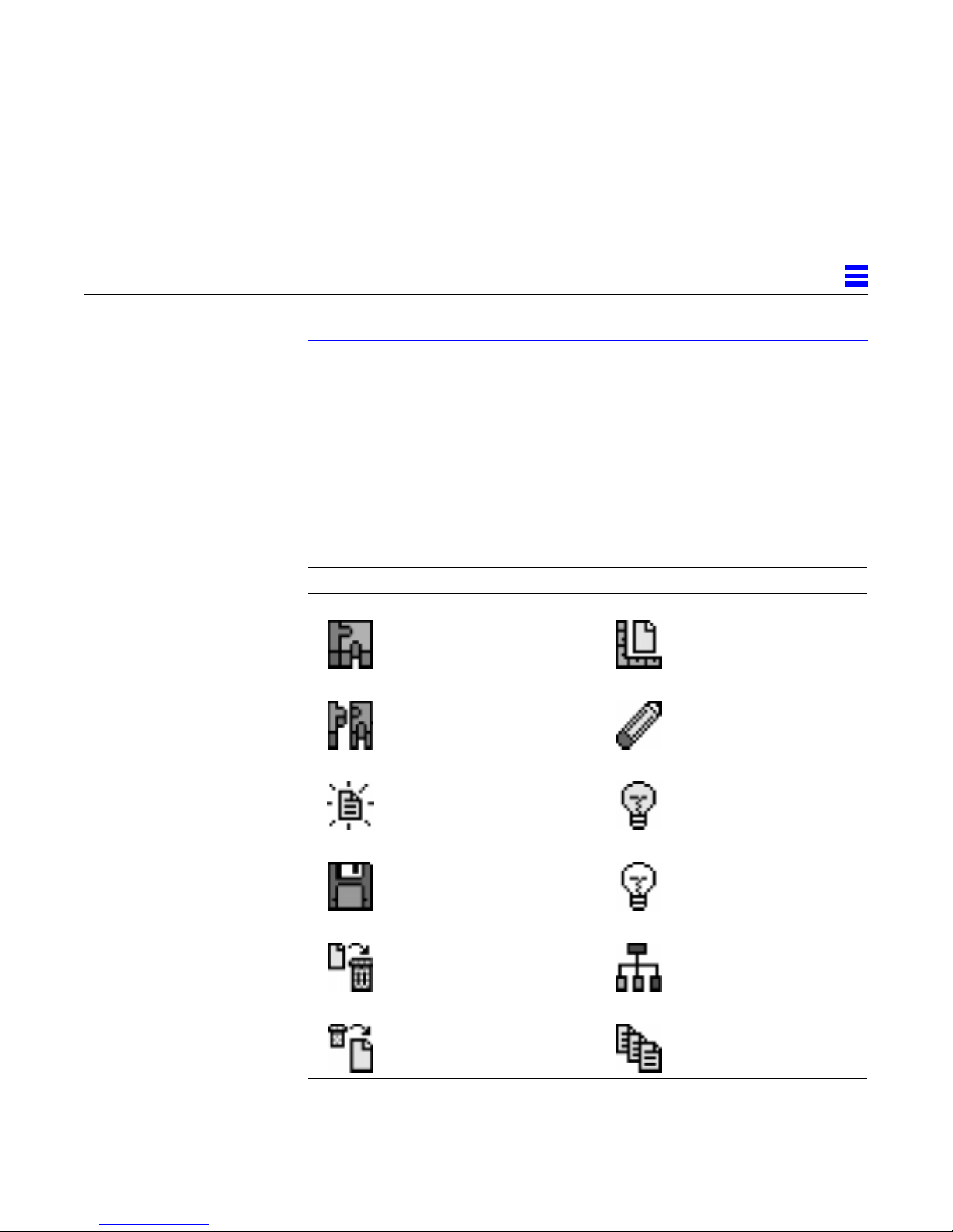
Note – Throughout this manual, whenever you are directed to initiate an
action, only one of the above methods is described. In most cases, you can use
any of the other methods as well.
2.6.1 Toolbar Buttons
The following table describes the toolbar buttons you can use to initiate an
action from the SunGMI.
Table 2-2 SunGMI Toolbar
Button Task Button Task
2
Connect to the domain. Modify the selected
resource.
Disconnect from the domain. Undo the last edit
operation.
Using the Administration Program 2-11
Create a new resource. Enable the selected
resource.
Save the open configuration. Disable the selected
resource.
Delete the selected resource. Display a new resource
window.
Cancel the deletion of the
selected resource.
Display a list of
configurations.
Page 60
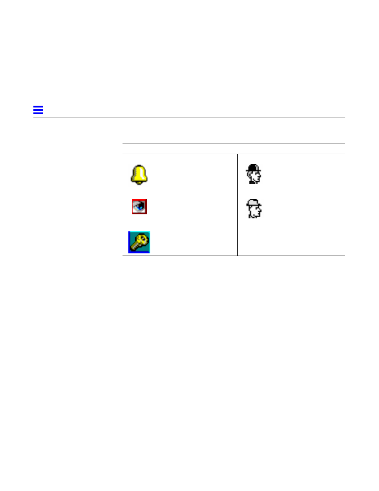
2
T able 2-2 SunGMI Toolbar
Button Task Button Task
Display the Events window. Display a list of manager
systems.
Display the Traces window. Display a list of
applications connected to
the domain.
Display the Licenses window .
2.6.2 Menu Commands
Menus are listed in the menu bar along the top of a window. To open a menu
and display the list of commands, either click the menu’s name in the menu
bar, or press Alt-x, where x is the underlined letter in the menu name. To select
a menu command, either drag the mouse to the desired command and release,
or press the underlined letter in the command name.
The menus available at a particular time and the commands available from a
particular menu depend on the currently selected window and resource.
Unavailable menu commands are grayed out and cannot be selected.
The following sections describe the commands available for each of the menus
in the menu bar.
2-12 SunLink SNA 9.1 PU2.1 Server Configuration Guide—August 1997
Page 61
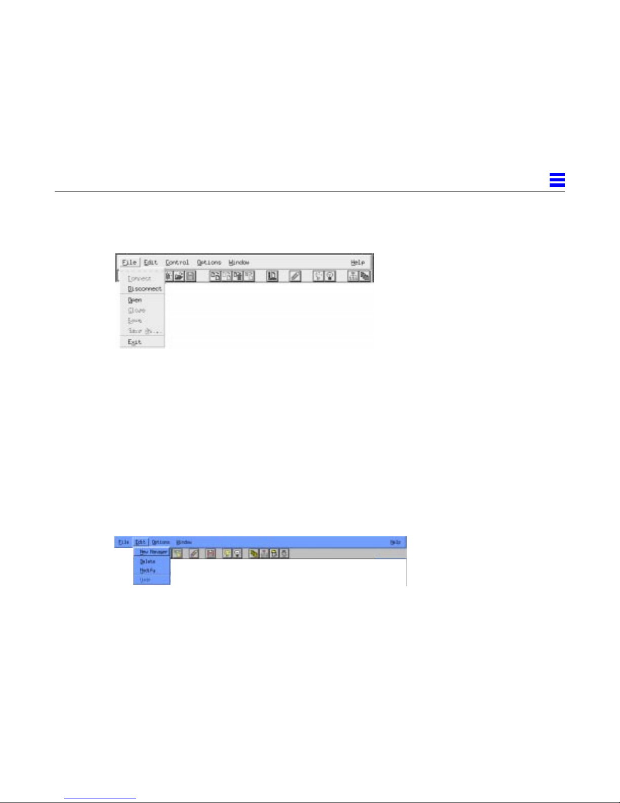
2.6.2.1 File Menu
Command Description
Connect Connects to a domain.
Disconnect Disconnects from a domain.
Open Opens a configuration.
Close Closes a configuration.
Save Saves a configuration.
Save As Saves a configuration with a new name.
Exit Exits the program.
2
2.6.2.2 Edit Menu
Command Description
New < > Creates a new: manager system, user, user group, LU
pool, system, server, SDLC line, Token Ring line, QLLC
line, physical unit (PU), dependent LU, independent
LU, partner LU, mode, or transaction program
(depending on the context).
Delete Deletes the selected item.
Undelete Undeletes the selected item.
Using the Administration Program 2-13
Page 62
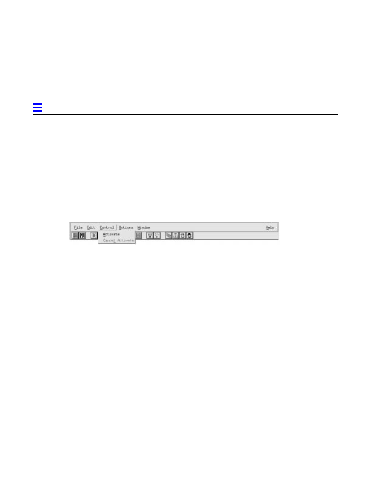
2
Modify Displays the configuration dialog box for the item you
want to modify.
Undo Undoes the last edit you made.
2.6.2.3 Control Menu
Note – The commands available from the Control menu depend on the
currently selected resource.
Command Description
Activate Makes an off-line configuration active.
Cancel Activate Cancels the pending activation of an off-line configuration.
Start Starts a system, PU2.1 server, trace, or physical unit (PU).
For more information, refer to Section 11.6, “Controlling the
Status of Resources,” on page 11-17.
Stop Stops a system, PU2.1 server, trace, connection, or PU. For
more information, refer to Section 11.6, “Controlling the
Status of Resources,” on page 11-17.
Create Trace Starts a PU2.1 server trace. For more information, refer to
Section 12.1.4.2, “Starting a PU2.1 Server Trace,” on
page 12-29.
Trace Line Opens the SunSCOPE utility and starts a line trace. For more
information, refer to Section 12.1.3.2, “Starting a Line Trace,”
on page 12-17.
Enable Enables a disabled dependent LU.
Disable Disables a dependent LU without affecting sessions or client
connections.
Forced Disable Disables a dependent LU, destroying sessions and client
connections.
2-14 SunLink SNA 9.1 PU2.1 Server Configuration Guide—August 1997
Page 63
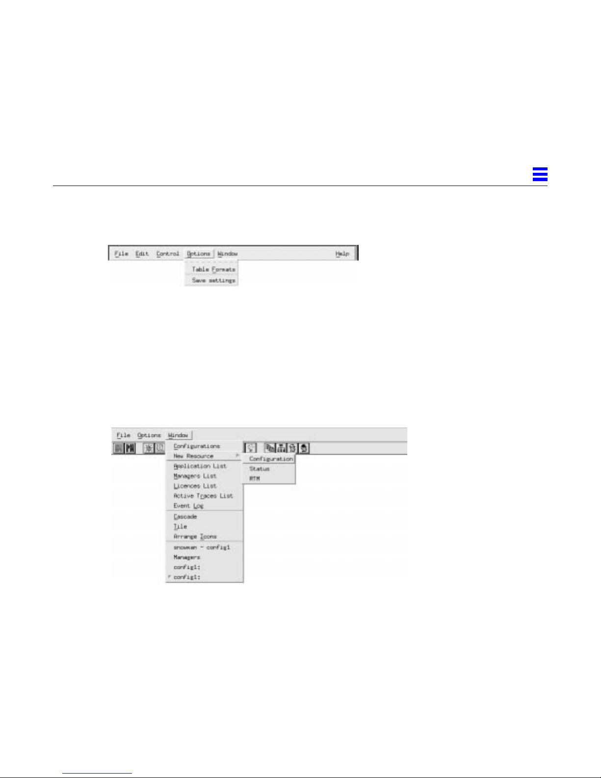
2.6.2.4 Options Menu
Command Description
Table Formats Allows you to modify the format of a resource table in a
resource window. For more information, refer to
Section 12.1.1.2, “Customizing a Table Format,” on
page 12-2.
Save settings Saves any settings you changed in this session.
2.6.2.5 Window Menu
2
Command Description
Configurations Displays the list of configuration windows.
New Resource Opens a new resource window with the resource table
displaying the selected type of information (Status,
RTM, IPRTM, or SNARTM).
Application List Displays a list of applications.
Managers List Displays a list of current manager systems.
Licenses List Displays the list of defined licenses.
Using the Administration Program 2-15
Page 64
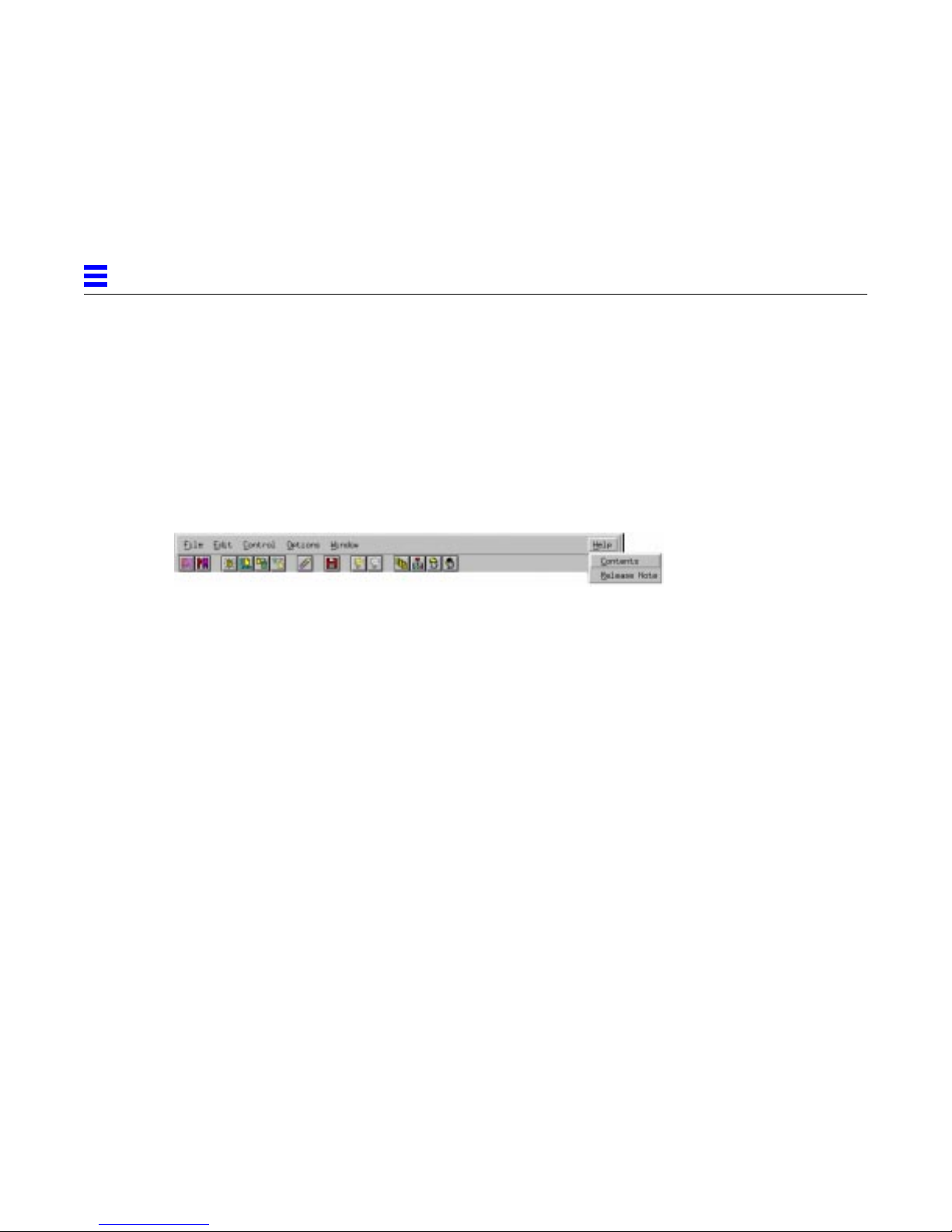
2
Active Traces List Displays the list of defined PU2.1 server traces.
Event Log Displays a list of current events.
Cascade Arranges windows in an overlapping display.
Tile Arranges windows edge-by-edge.
Arrange Icons Rearranges the icons on your desktop.
2.6.2.6 Help Menu
Command Description
Contents Displays the contents of the Help System.
Release Note Displays the latest version of the Sun PU2.1 SNA Server
release notes.
2.7 Using Dialog Boxes
To customize the operation of the Sun PU2.1 SNA Server, you use the SunGMI
to configure objects, such as systems, PU2.1 servers, users, and dependent LUs.
For each object that you configure, the SunGMI provides one or two dialog
boxes that contain parameters appropriate to the object. The Basic dialog box
typically contains required parameters, while the Advanced dialog box
typically contains optional parameters.
You specify the setting of a parameter either by entering data into a text box,
by selecting an item from a drop-down menu, or by checking/clearing a check
box. Dialog boxes also contain action buttons. The action buttons are described
in the following table.
2-16 SunLink SNA 9.1 PU2.1 Server Configuration Guide—August 1997
Page 65

2
Table 2-3 Dialog Action Buttons
Button Action
OK Accept the parameter settings.
Cancel Exit the dialog box without accepting the parameter
settings.
Reset Return all parameters to their initial default settings.
Advanced Display the Advanced dialog box.
Basic Display the Basic dialog box.
Help Display the contents of the Help system for the object.
The keyboard shortcuts you can use when entering information in a dialog box
are described in the following table.
Table 2-4 Keyboard Shortcuts
Key Action
Tab Move forward from one parameter to the next
parameter.
Shift-Tab Move backward from one parameter to the previous
Spacebar Toggle between enabling and disabling a check box.
Delete Delete the setting of a parameter, returning the
Using the Administration Program 2-17
parameter.
parameter to its default value.
Page 66

2
2-18 SunLink SNA 9.1 PU2.1 Server Configuration Guide—August 1997
Page 67

Getting Started
This chapter contains the following sections:
3
• Overview of Configuration Tasks - a list of the tasks required to get you up
and running with the Sun PU2.1 SNA Server as quickly as possible.
• Starting the SunGMAN - describes how to start the Sun Gateway Manager.
• Starting the SunGMI - describes how to start the Sun Graphical Manager
Interface.
• Creating a Configuration - describes how to create a configuration and how
to add a system, a PU2.1 server, a connection, a physical unit (PU), and a
dependent logical unit (LU) to the configuration.
Note – This chapter is intended to get you up and running quickly. It assumes
that you are creating a manager network consisting of a single system. At a
later time, you can add additional manager systems to the manager network
for increased redundancy and reliability; add additional PU2.1 servers to each
system; create LU pools for dependent LUs; set up users and user groups;
configure additional components, such as those related to LU6.2 and
independent LUs; and run client SNA programs on other systems in your
network, using the Sun PU2.1 SNA Server as a gateway to the SNA network.
For more information, refer to the remainder of this manual and to the
appropriate Sun PU2.1 SNA Server Planning and Installation Guide.
3-1
Page 68
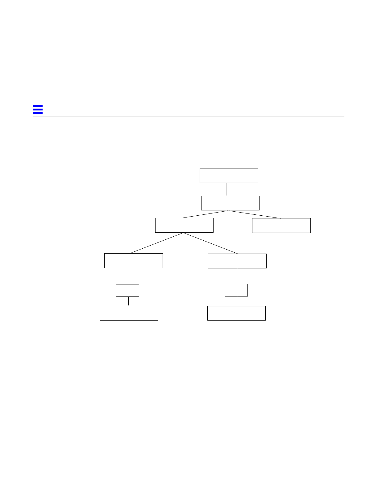
3
3.1 Overview of Configuration T asks
The following figure illustrates the components you must configure to get up
and running with the Sun PU2.1 SNA Server.
Configuration
System
PU2.1 Server
SDLC Line
PU2
Dependent LU
Figure 3-1 Configuration Hierarchy
The tasks required to get the Sun PU2.1 SNA Server up and running are as
follows:
1. Plan the configuration of the Sun PU2.1 SNA Server. Refer to Appendix A,
“Resource Planning Forms."
2. Update the Domain Name System (DNS) configuration, if necessary. Refer
to Section B.3, “Updating the DNS Configuration,” on page B-5.
LAN Connection
PU2
Dependent LU
PU2.1 Server
3. Install any required communication hardware and software. Refer to the
3-2 SunLink SNA 9.1 PU2.1 Server Configuration Guide—August 1997
appropriate Sun PU2.1 SNA Server Planning and Installation Guide.
Page 69

3
4. Install the Sun Gateway Manager (SunGMAN) and Sun Graphical
Management Interface (SunGMI) software. Refer to the appropriate Sun
PU2.1 SNA Server Planning and Installation Guide.
5. Install the Sun PU2.1 SNA Server software on the system that contains the
communication hardware that connects to your IBM SNA environment.
Refer to the appropriate Sun PU2.1 SNA Server Planning and Installation
Guide.
6. Create a configuration, if necessary. Refer to Section 3.4, “Creating a
Configuration,” on page 3-4.
7. Configure the system. Refer to Section 3.4.2, “Configuring a System,” on
page 3-5.
8. Add a PU2.1 server. Refer to Section 3.4.3, “Adding a PU2.1 Server,” on
page 3-6.
9. Add the appropriate connection. Refer to Section 3.4.4, “Adding a
Connection,” on page 3-7.
10. Add a PU. Refer to Section 3.4.5, “Adding a PU,” on page 3-10.
11. Add a dependent LU. Refer to Section 3.4.6, “Adding a Dependent LU,”
on page 3-11.
12. Save the configuration. Refer to Section 3.4.7, “Saving the New
Configuration,” on page 3-13.
13. Install the appropriate Sun SNA clients. Refer to the appropriate Sun
PU2.1 SNA Server Planning and Installation Manual for information on
configuring the Sun PU2.1 SNA Server for use with your particular client.
14. Before you begin operations, make sure that you have licenses for each of
your client connections. For more information about adding licenses, refer
to Section 11.2, “Managing Licenses,” on page 11-6.
3.2 Starting the SunGMAN
When you install the SunGMAN software, start-up scripts that run when the
Unix system boots up are created and linked to the start-up area. To start the
SunGMAN manually, use the sunsetup command. By default, sunsetup is
located in the /etc/Sun directory.
Getting Started 3-3
Page 70
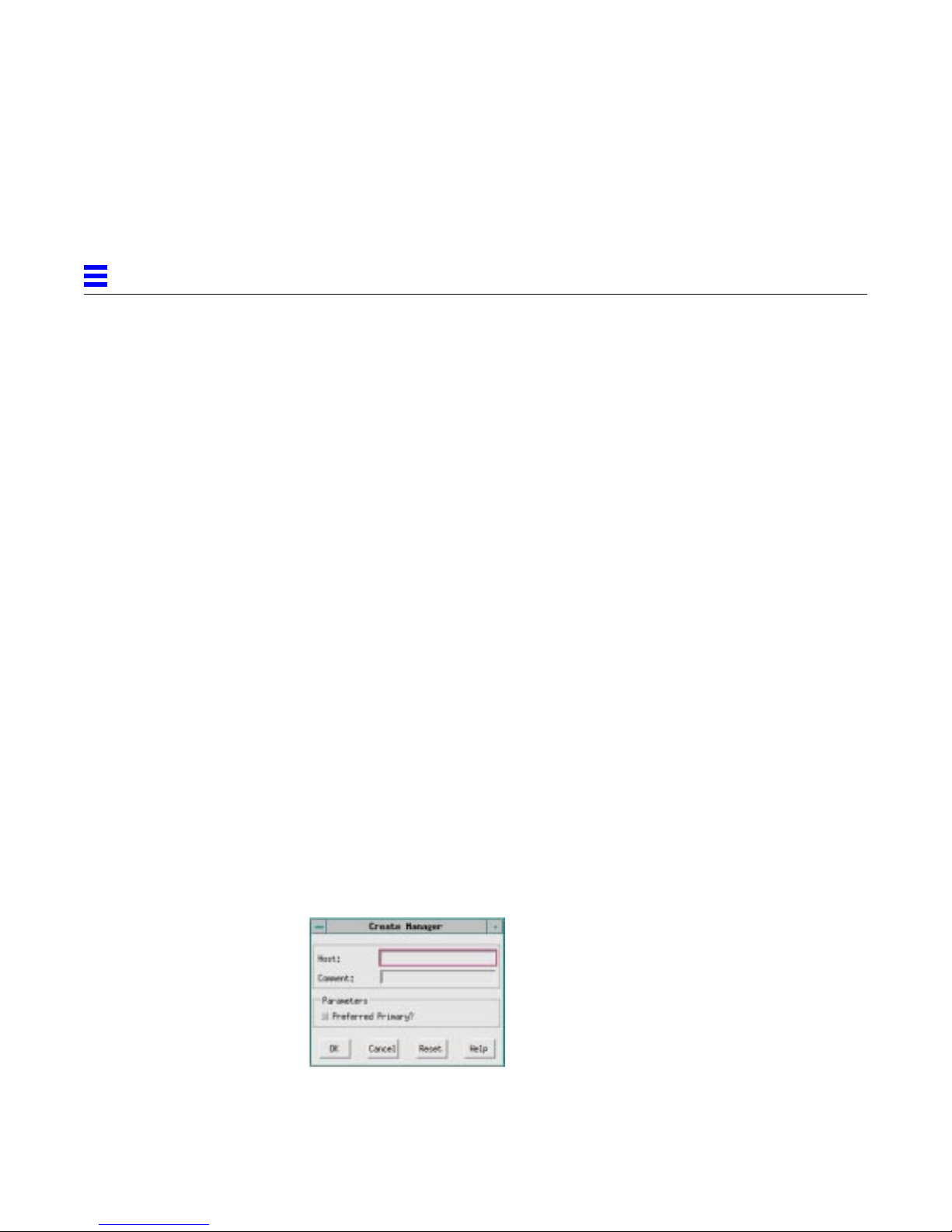
3
3.3 Starting the SunGMI
To start the SunGMI, enter the sungmi command at the shell prompt. The
SunGMI is linked to the /usr/bin directory (unless a different directory is
chosen during installation) and should be in your path in most environments.
For general information on how to use the SunGMI, refer to Chapter 2, “Using
the Administration Program."
3.4 Creating a Configuration
After you start the SunGMI and connect to a domain, the screen displays the
configuration window. The Sun PU2.1 SNA Server is installed with a
configuration called config1. The following sections describe how to create a
manager system; how to configure a system, a PU2.1 server, a connection, a
PU, and a dependent LU for config1; and how to save the configuration.
3.4.1 Creating a Manager System
▼ To create a manager system:
1. Highlight config1 in the configuration window, and then select
File → Open from the menu bar to display the resource window for
config1.
2. Select Window → Managers List to display the list of the manager systems
that are defined for config1.
3. Select Edit → New Manager from the menu bar to display the Create
Manager dialog box.
3-4 SunLink SNA 9.1 PU2.1 Server Configuration Guide—August 1997
Page 71
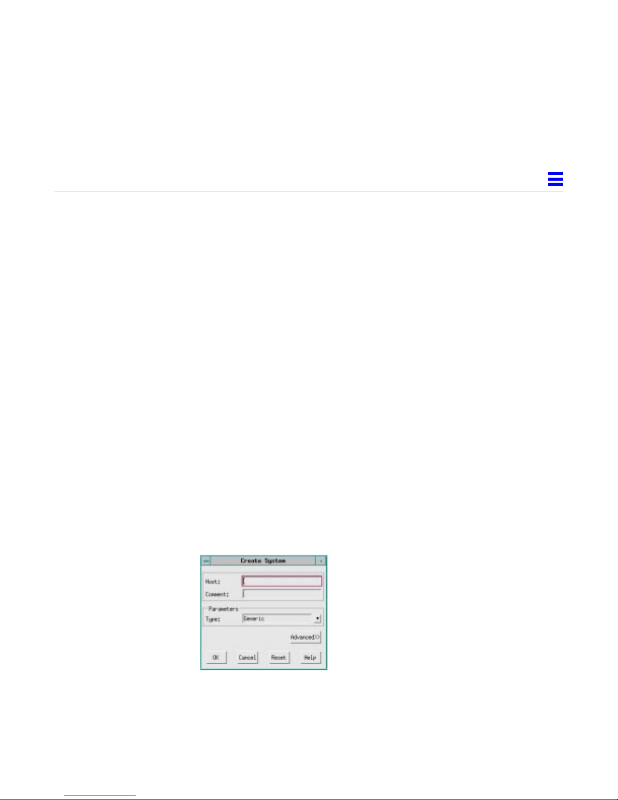
4. In the Host field, enter the hostname of the machine on which you
installed the SunGMAN software.
5. Typically, you can leave the default settings for the remaining parameters.
If you want to change any of the other parameters, refer to Section 11.3.2,
“Adding a Manager System,” on page 11-9.
6. Click OK to add the manager system to the manager network.
3.4.2 Configuring a System
▼ To configure a system:
1. Double-click the configuration you are using to display the resource
window.
2. Click Systems in the resource tree to select it.
If this is a new installation or if, during the installation procedure, you
specified that you wanted to run the manager system as the primary
manager system in your manager network, an entry for the local system is
automatically created. Go to the next section to add a PU2.1 server to the
system.
3
3. From the main window, select Edit → New → System to display the Create
4. In the Host field, enter the hostname of the system on which you installed
Getting Started 3-5
If you must create a new system, go to step 3.
System dialog box.
the Sun PU2.1 SNA Server.
Page 72
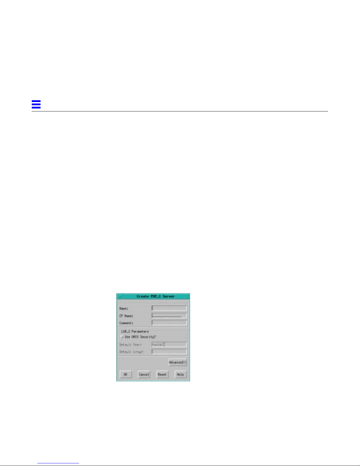
3
5. In the Type field, select the platform on which the server will run. Make
sure that you select the appropriate platform. Do not use the default
setting (Generic).
6. Typically, you can leave the default settings for the remaining parameters
in the Basic and Advanced dialog boxes. If you want to change any of the
other parameters, refer to Chapter 4, “Configuring Systems."
7. Click OK to add the system to the configuration.
3.4.3 Adding a PU2.1 Server
▼ To add a PU2.1 server to run on the system:
1. Double-click Systems in the resource tree to display the name of the
system you just added.
2. Double-click the system name to open its subordinate entries.
3. Click PU2.1 Servers in the resource tree to open a new resource table.
4. From the main window, select Edit → New → PU2.1 Server to display the
Create PU2.1 Server dialog box.
5. In the Name field, enter the name for the new PU2.1 server. The name can
contain up to eight alphanumeric characters (including @, #, and $). Tabs
and spaces are not allowed. The first character cannot be a number. The
name cannot be the same as any other PU2.1 server name.
3-6 SunLink SNA 9.1 PU2.1 Server Configuration Guide—August 1997
Page 73
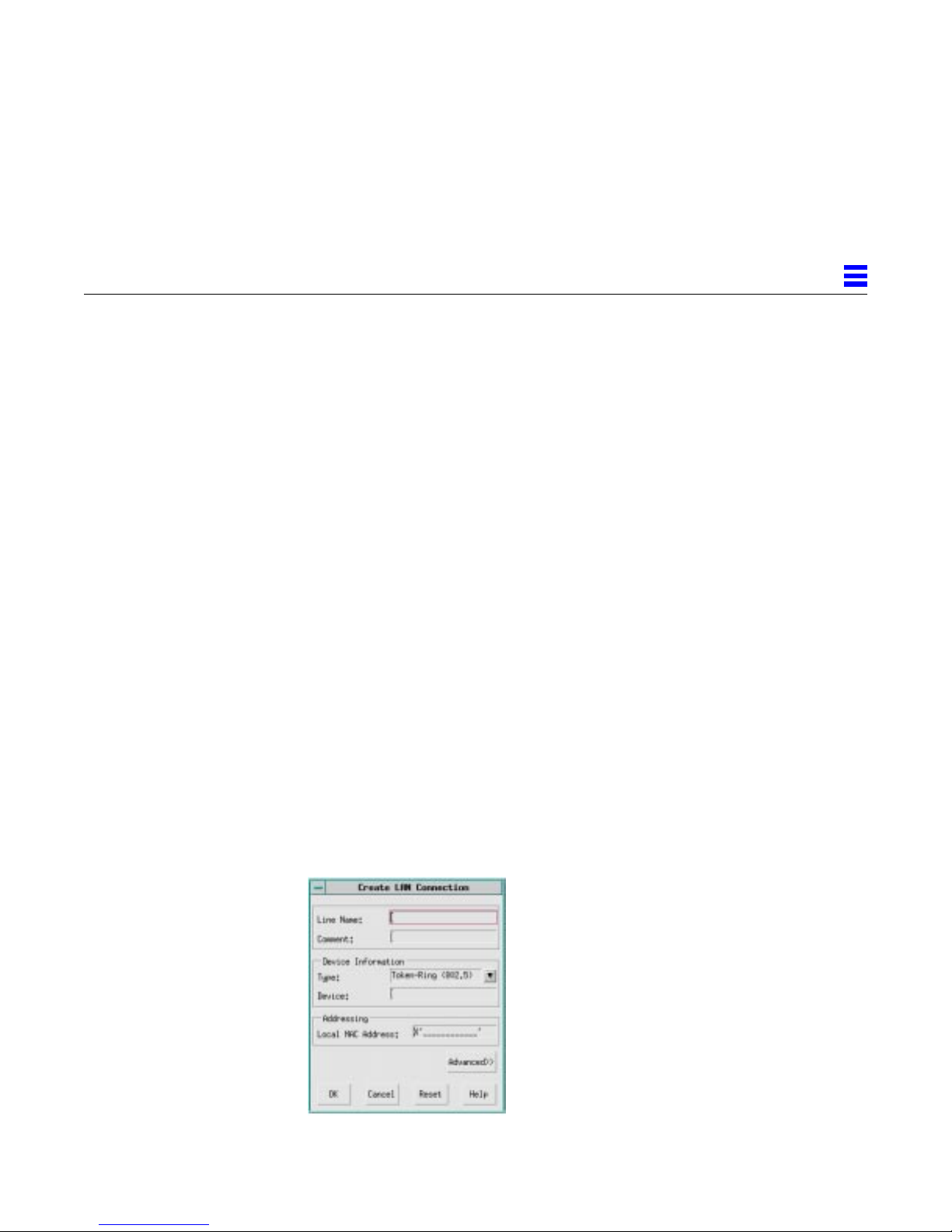
6. In the CP Name field, enter either the CP Name assigned by your IBM
network administrator or the name you entered in the Name field.
7. Click Advanced, tab to the SunOp Service field, and enter sunadmin_pu2,
if necessary. (Note that sunadmin_pu2 is the name of the service added to
the database during installation.)
8. Typically, you can leave the default settings for the remaining parameters
in the Basic and Advanced dialog boxes. If you want to change any of the
other parameters, refer to Chapter 5, “Configuring PU2.1 Servers."
9. Click OK to add the PU2.1 server to the system.
3.4.4 Adding a Connection
This section describes how to add a local area network (LAN), SDLC, or QLLC
connection to your configuration.
▼ To add a LAN connection:
1. Double-click PU2.1 Servers in the resource tree to display the name of the
PU2.1 server you just added.
3
2. Double-click the PU2.1 server name to open its subordinate entries.
3. Click LAN Connections in the resource tree.
4. From the main window, select Edit → New → LAN Connection to display
Getting Started 3-7
the Create LAN Connection dialog box.
Page 74
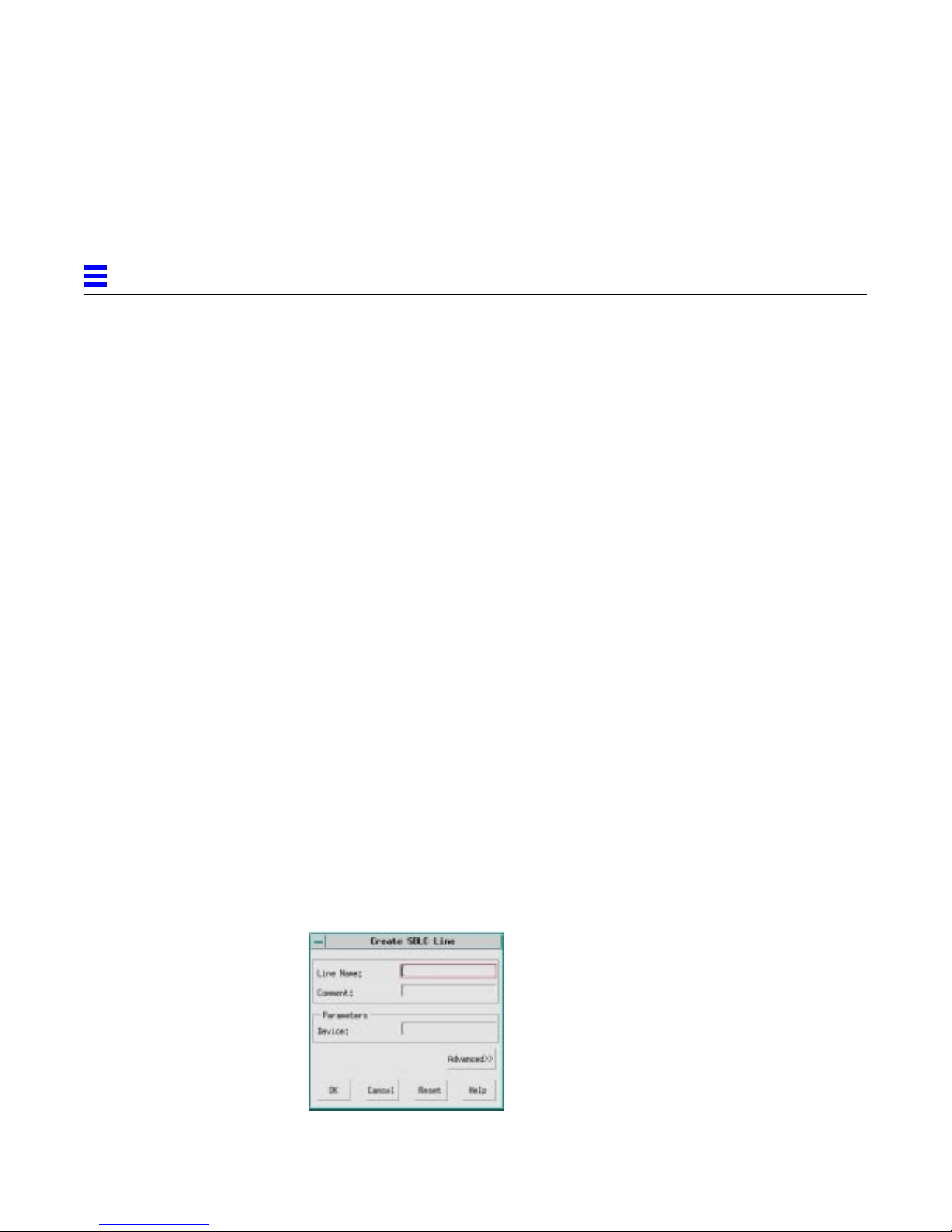
3
5. In the Line Name field, enter the name for the new line. The name can
contain up to eight alphanumeric characters (including @, #, and $). Tabs
and spaces are not allowed. The first character cannot be a number. The
name cannot be the same as any other connection name.
6. In the Type field, select Token Ring, Ethernet, or FDDI, as appropriate.
Note that Ethernet and FDDI are not supported on all platforms.
7. In the MAC Address field, enter the Medium Access Control (MAC)
address for the local station. See your host network administrator for the
correct value.
8. If you are running on a 16 Mb/s Token Ring, click Advanced, tab to the
LAN Speed field, and select 16 Mb/s.
9. Typically, you can leave the default settings for the remaining parameters
in the Basic and Advanced dialog boxes. If you want to change any of the
other parameters, refer to Section 6.1, “Adding a LAN Connection,” on
page 6-1.
10. Click OK to add the new LAN connection.
▼ To add an SDLC connection:
1. Double-click PU2.1 Servers in the resource tree to display the name of the
PU2.1 server you just added.
2. Double-click the PU2.1 server name to open its subordinate entries.
3. Click SDLC Lines in the resource tree.
4. From the main window, select Edit → New → SDLC Line to display the
Create SDLC Line dialog box.
3-8 SunLink SNA 9.1 PU2.1 Server Configuration Guide—August 1997
Page 75
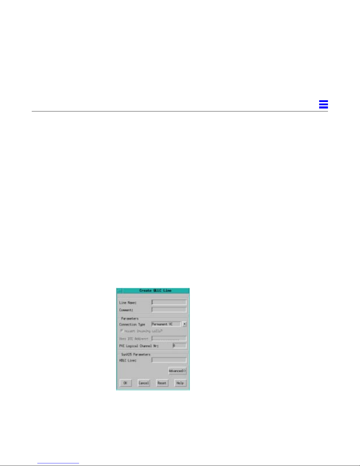
5. In the Line Name field, enter a name for the new SDLC line. The name
can contain up to eight alphanumeric characters (including @, #, and $).
Tabs and spaces are not allowed. The first character cannot be a number.
The name cannot be the same as any other connection name.
6. Typically, you can leave the default settings for the remaining parameters
in the Basic and Advanced dialog boxes. If you want to change any of the
other parameters, refer to Section 6.2, “Adding an SDLC Connection,” on
page 6-4.
7. Click OK to add the new SDLC line.
▼ To add a QLLC connection:
1. Double-click PU2.1 Servers in the resource tree to display the name of the
PU2.1 server you just added.
2. Double-click the PU2.1 server name to open its subordinate entries.
3. Click QLLC Lines in the resource tree.
4. From the main window, select Edit → New → QLLC Line to display the
Create QLLC Line dialog box.
3
Getting Started 3-9
Page 76
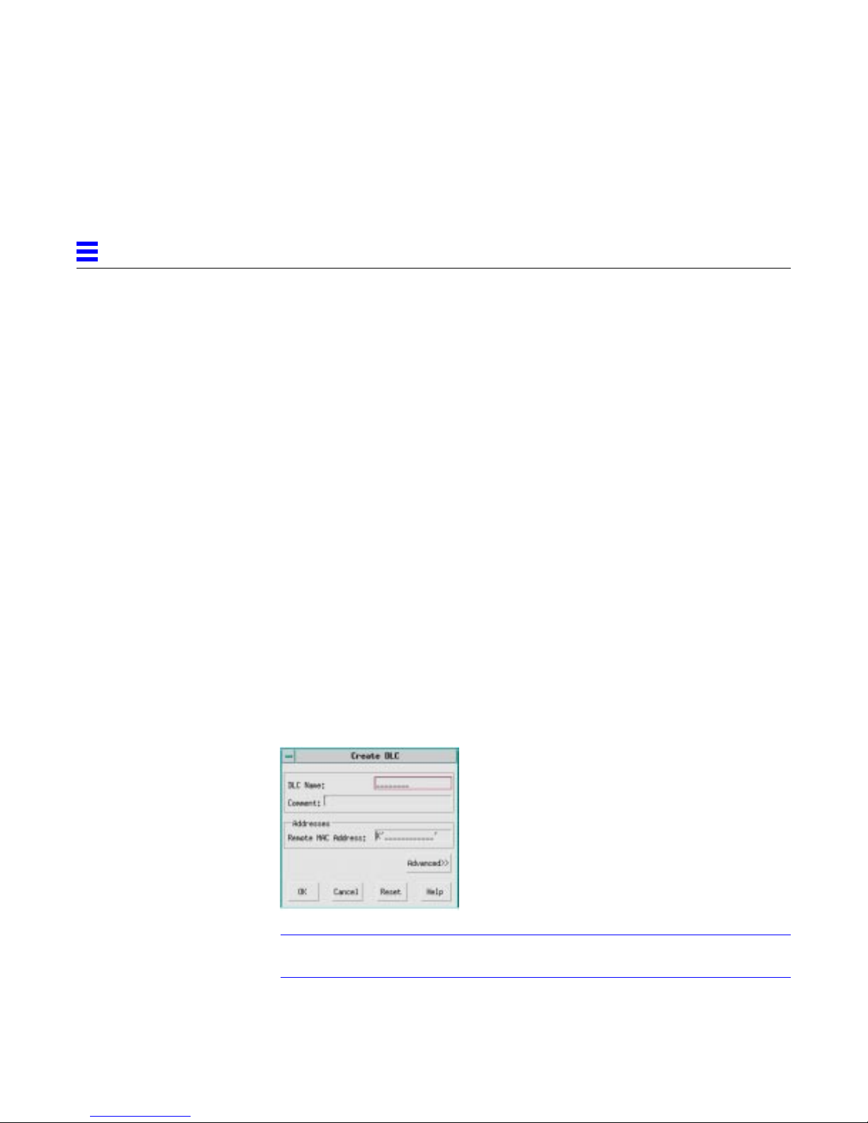
3
5. In the Line Name field, enter a name for the new QLLC line. The name
can contain up to eight alphanumeric characters (including @, #, and $).
Tabs and spaces are not allowed. The first character cannot be a number.
The name cannot be the same as any other connection name.
6. Typically, you can leave the default settings for the remaining parameters
in the Basic and Advanced dialog boxes. If you want to change any of the
other parameters, refer to Section 6.3, “Adding a QLLC Connection,” on
page 6-7.
7. Click OK to add the new QLLC line.
3.4.5 Adding a PU
▼ To add a PU:
1. In the resource tree, double-click LAN Connections (for Token Ring,
Ethernet, or FDDI connections), SDLC Lines (for SDLC connections), or
QLLC Lines (for QLLC connections) to display the name of the connection
you just added.
2. Click the connection name to select it.
3. From the main window, select Edit → New → DLC (PU2) to display the
Create DLC dialog box.
Note – The dialog box shown is for a LAN connection. The parameters
available for SDLC, QLLC, and channel connections may vary.
3-10 SunLink SNA 9.1 PU2.1 Server Configuration Guide—August 1997
Page 77

4. In the DLC Name field, enter the name for the new PU. The name can
contain up to eight alphanumeric characters (including @, #, and $). Tabs
and spaces are not allowed. The first character cannot be a number.
Lowercase letters are converted to uppercase. The name cannot be the
same as any other PU, dependent LU, independent LU, or LU pool name.
Sun recommends that you use the name that is defined in the IBM
VTAM/NCP configuration. For more information, refer to IBM's VTAM
Installation and Resource Definition manual.
5. If your IBM network definitions contain an IDBLK/IDNUM setting, click
Advanced, tab to the Local Terminal ID field, and enter the
IDBLK/IDNUM setting.
6. Typically, you can leave the default settings for the remaining parameters
in the Basic and Advanced dialog boxes. If you want to change any of the
other parameters, refer to Chapter 7, “Configuring PUs."
7. Click OK to add the new PU.
3.4.6 Adding a Dependent LU
3
▼ To add a dependent LU:
1. Double-click the connection name in the resource tree to display the name
of the PU you just added.
2. Click the PU name to select it.
3. From the main window, select Edit → New → Dependent LU to display
the Create Dependent LU dialog box.
Note that the dialog box shown is for a LAN connection. The parameters
available for SDLC, QLLC, and channel connections may vary.
Getting Started 3-11
Page 78
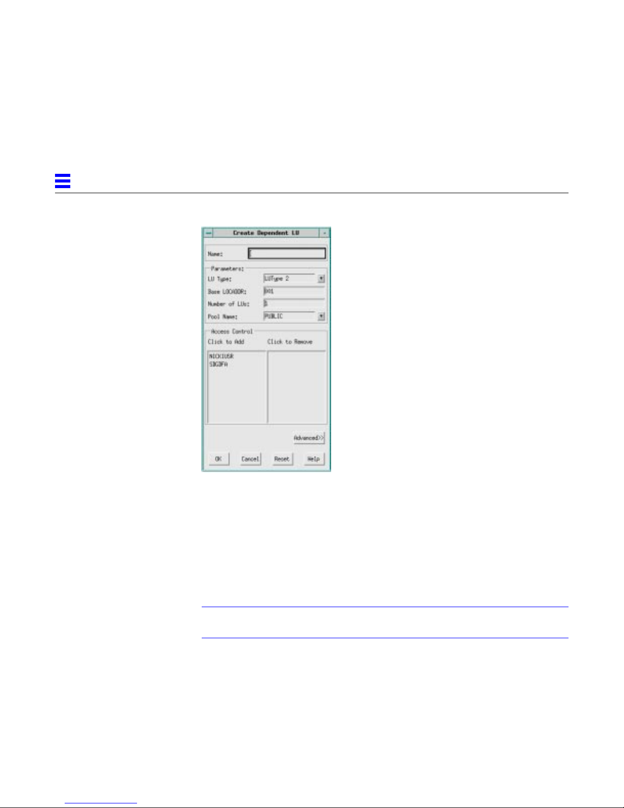
3
4. In the Name field, enter the name for the dependent LU. The name can
contain up to eight alphanumeric characters (including @, #, and $). Tabs
and spaces are not allowed. The first character cannot be a number.
Lowercase letters are converted to uppercase. The name cannot be the
same as any other dependent LU, independent LU, LU pool, or PU name.
5. In the LU Type field, select the dependent LU type. Select LUType 1 for
3770 RJE. Select LUType 2 for 3270 terminal emulation. Select LUType 3
for printing. Select LUType 6.2 for APPC peer-to-peer communications.
Note – If you are using either an LUType 1 or an LUType 3 for printing, always
select LUType 3.
6. Typically, you can leave the default settings for the remaining parameters
in the Basic and Advanced dialog boxes. If you want to change any of the
other parameters, refer to Chapter 8, “Configuring Dependent LUs."
7. Click OK to add the dependent LU.
3-12 SunLink SNA 9.1 PU2.1 Server Configuration Guide—August 1997
Page 79

3.4.7 Saving the New Configuration
▼ To save the new configuration:
1. From the main window, either select File → Save to save the configuration
as config1 or select File → Save As to save the configuration with a new
name. The screen displays the Save dialog box.
2. Click Changes should be made immediately and then click Yes in the
confirmation dialog box. The new configuration files are copied to the
PU2.1 server and the required processes are started/restarted on the
system.
3. While the processes are starting, the status of the system and PU2.1 server,
as shown in the configuration window, changes to Pending-Active. After
the processes start, the status changes to Active. The PU and LU entities
contained in the PU2.1 server change to Active when the IBM SNA
network activates them.
Note – The SNA host (VTAM) must activate its connections to the Sun PU2.1
SNA Server. Refer to IBM's NetView Operations manual for activation,
deactivation, and display commands for SNA resources.
3
4. To stop a process once it has been started, select the system or PU2.1
Getting Started 3-13
server from the resource tree and select Control → Stop System or Control
→ Stop Server
Page 80

3
3-14 SunLink SNA 9.1 PU2.1 Server Configuration Guide—August 1997
Page 81

Configuring Systems
This chapter describes how to configure the systems that make up your Sun
PU2.1 SNA Server. Before you begin, identify the systems that provide
connectivity into your SNA network and define the distribution of functions
among these systems. Use the hardware and software configuration planning
forms in Appendix A, “Resource Planning Forms,” to help you plan your
system configuration.
▼ To configure a system:
1. Double-click the appropriate configuration in the configuration window
to display the resource window.
2. Using the right mouse button (MB3), click and hold Systems in the
resource tree and select New → System from the popup menu. The screen
displays the Create System dialog box.
3. Enter the appropriate information in the Basic dialog box and then click
Advanced to display the Advanced dialog box. The following sections
describe the parameters in the Basic and Advanced dialog boxes.
4. To accept the settings, click OK. To exit a dialog box without accepting the
settings, click Cancel. To return to the default settings, click Reset.
4
4-1
Page 82
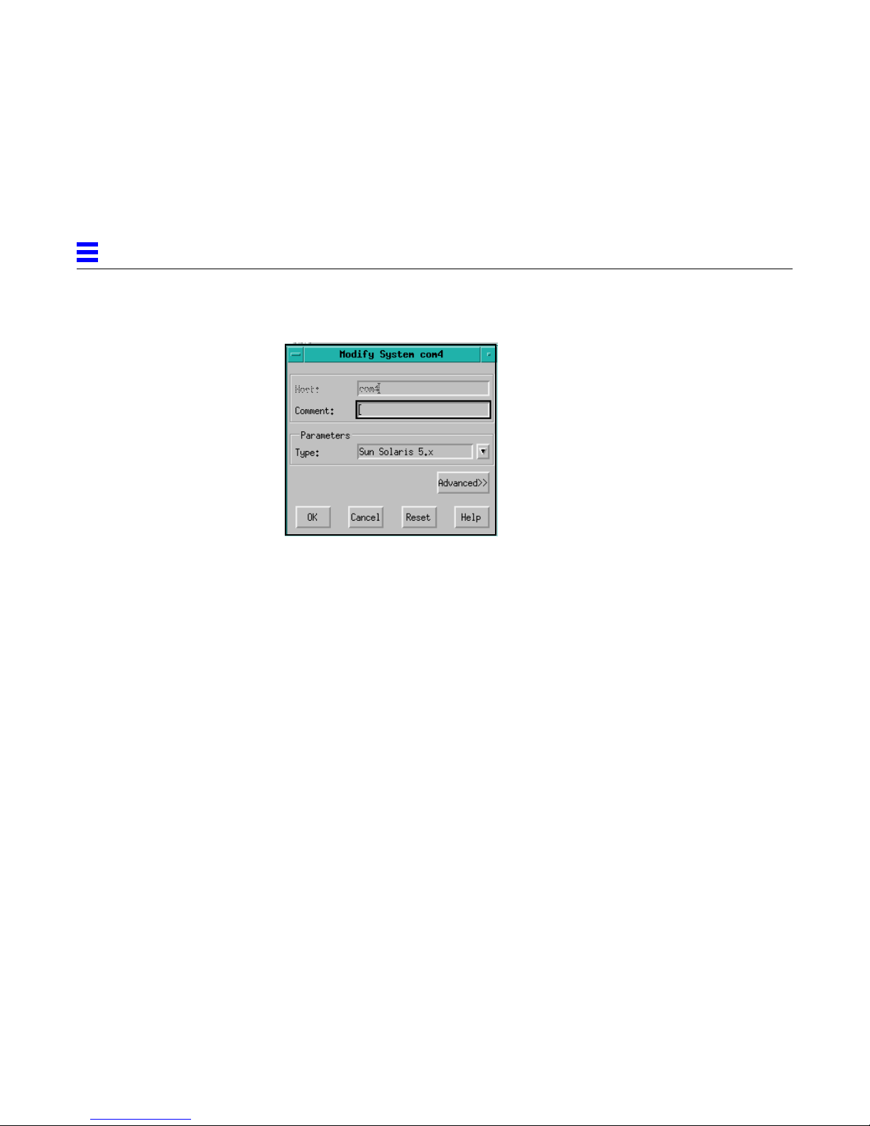
4
4.1 Basic System Configuration
Host
The name of the system on which the servers are configured and run. You
must specify the name of the system. The name cannot be the same as any
other system name.
Comment
A free-form text area that you can use to further qualify and describe the
system configuration.
Type
The platform on which the servers run. This setting assures that platformspecific parameters are controlled correctly. Select Generic for unsupported
platforms.
Sun recommends that you always select an appropriate platform and that you
do not select the Generic option.
4-2 SunLink SNA 9.1 PU2.1 Server Configuration Guide—August 1997
Page 83
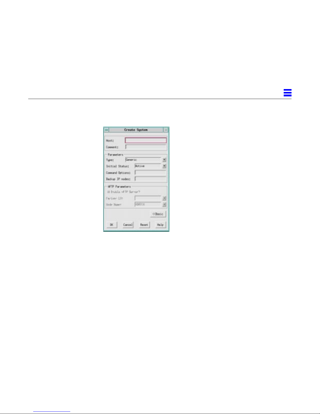
4.2 Advanced System Configuration
Initial Status
The initial status of the system when it is initialized. The value can be Active or
Inactive. If you select Active, the Sun System Manager (sunsman) is activated
when the system is initialized. If you select Inactive, you must manually
activate the sunsman.
4
Command Options
The command line options that you can use when activating the sunsman.
Separate command line options with a space. The following table lists valid
command line options.
Configuring Systems 4-3
Page 84

4
Table 4-1 Command Line Options
Option Description
-b number_seconds Set the time that an LU that was in session must
wait before attaching to another client to
number_seconds seconds.
1
-D
-F file_descriptors Set the number of file descriptors sunsman can
-N port_number
-o number_seconds
-O number_seconds Set the time to wait for a response from a client
1
1
Trace SNMP packets. This command line option is
valid only if you use the -t command line option to
enable line tracing.
support to file_descriptors.
Set the port on which to listen for Telnet connections
to port_number.
Set the time sunsman should wait for a response
from a PU2.1 server before dropping the queued
request to number_seconds.
during Telnet options negotiation to number_seconds
seconds. If you do not use this command line
option, no time-out value is used. If the time expires,
negotiations start again, omitting the option that
initiated the time-out.
-S interval When sending status messages to a client’s screen,
-t trace_flag
-T Use the terminal type when determining which LU
-v Print the sunsman version.
-W number_seconds Set the time sunsman should wait for a response
1. Do not use this command line option unless you are instructed to do so by
4-4 SunLink SNA 9.1 PU2.1 Server Configuration Guide—August 1997
1
Sun Technical Support.
wait interval seconds before overwriting.
Enable line tracing and set the type of internal traces
to capture in the trace file to trace_flag. Sun
recommends that you always set trace_flag to -1,
indicating all trace flags.
to match to an incoming client request.
when attempting to acquire an LU from a PU2.1
server to number_seconds.
Page 85

Enable AFTP Server?
Partner LU
Mode Name
4
Indicates whether the AFTP (APPC File Transfer Protocol) server functions are
enabled. Check the box to enable the AFTP server. Clear the box to disable the
AFTP server.
Note – This parameter is available only if you have configured a partner LU.
For more information, refer to Section 9.2, “Configuring a Partner LU,” on
page 9-4.
If you are using an IBM mainframe or mid-range system that supports an
AFTP server to send/receive files to/from internetwork FTP client software,
make sure that you enable the AFTP server after you configure the partner LU.
For more information on using AFTP, refer to Section 4.3, “Using APPC File
Transfer Protocol."
The partner LU name used to establish the AFTP session. This name must
match the Name specified in the partner LU configuration. For more
information, refer to Section 9.2, “Configuring a Partner LU,” on page 9-4.
The mode used to establish the AFTP session. This name must match the Mode
Name specified in the session mode configuration. For more information, refer
to Section 9.3, “Configuring the Session Mode,” on page 9-7.
4.3 Using APPC File T ransfer Protocol
SunLink 9.1 AFTP functions as a Client to IBM's APPC Application Suite
(ASuite) AFTPD Server. IBM supplies ASuite as part of VTAM 4.2.
Users connect to the SunLink 9.1 AFTP Client via TCP/IP FTP - port 8021. The
SunLink 9.1 AFTP Client connects to the host system via an APPC
conversation. The translation from TCP/IP FTP protocol to SNA APPC
protocol is done by the SunLink 9.1 AFTP Client.
ASuite support under the VM/ESA and MVS/ESA is documented in:
• AAPC Application Suite Administration - SC31-6533
• APPC Application Suite User's Guide - SC31-6532.
Configuring Systems 4-5
Page 86
4
AFTP supports text file transfer to and from VM/ESA and MVS/ESA. AFTP
also supports binary file transfer from the client to the host and back - i.e.,
client (for example, Unix) binary files can be stored on the host and retrieved
by other clients. Although the reverse operation can probably be made to work
(host executable modules stored on client workstations, and retrieved by other
hosts), it is not supported.
▼ To configure AFTP on SunLink 9.1:
1. On GMI: configure an Independent LU under one of the PU2.1 Servers.
The Local LUName is arbitrary.
2. Under this Independent LU: configure a PartnerLU with alias 'XFTPD'.
The fully qualified Partner LU Name is the name of the AFTPD Server on
the host.
• See the manuals above for VM/ESA and MVS/ESA configuration.
• See below for an example of VM/ESA configuration.
3. Under XFTPD, configure mode #BATCH. Set up session limits as desired
for ConWinner and ConLoser: for example, 4 of each is typical.
4. Configure the AFTP LU 6.2 Definition in VTAMLST:
T015L000 LU LOCADDR=0, X
DLOGMOD=SNASVCMG
4.3.1 Sample setup for VM/ESA
1. Set up a UserID for AVSVM, which provides the APPC Support under
VM.
4-6 SunLink SNA 9.1 PU2.1 Server Configuration Guide—August 1997
Page 87
USER AVSVM AVSVM 32M 64M BG
* AVS virtual machine
INCLUDE GCSPROF
ACCOUNT 7 P390
IUCV ANY
IUCV *IDENT GATEANY GATEWAY REVOKE
IUCV ALLOW
OPTION COMSRV MAXCONN 20 ACCT
CONSOLE 01F 3215 T OPERATOR
LINK MAINT 193 193 RR
MDISK 191 FB-512 16 3504 AVSVM MR ALL
2. Set up the VTAM Application Major Node for AVSVM:
*
AVSVM VBUILD TYPE=APPL
*
AGWAFTPD APPL APPC=YES,AUTHEXIT=YES,AUTOSES=10, X
DSESLIM=100,DMINWNL=50,DMIWNR=50, X
MODETAB=AGWTAB,PARSESS=YES,SYNCLVL=SYNCPT, X
SECACPT=ALREADYV
4
In the case, the Partner LU defined by XFTPD is:
network_name.AGWAFTPD
3. Set up AGWPROF GCS for AVSVM. The PROFILE GCS for AVS is
Configuring Systems 4-7
supplied with the system.
Page 88
4
/********************************************************************/
/* */
/* SAMPLE AGWPROF GCS FOR AVS */
/* */
/********************************************************************/
'AGW ACTIVATE GATEWAY AGWAFTPD PRIVATE USERID AFTPD' ;
Note – VM UserID AFTPD will act as the AFTP Server, and is configured as a
Private, Dedicated Gateway to AVS. Also note that this statement connects the
VTAM APPL Node AGWAFTPD with the AFTPD UserID. Incoming Binds for
AGWAFTPD will be routed to the AFTP Server running on UserID AFTPD.
4. Set up the AFTPD UserID. Note that the ASuite UserID is 5654025, and
the ASuite files are on the 2C2 and 29A mdisks:
USER AFTPD AFTPD 16M 32M ABG
* Configurator generated USERID Fri Nov 22 10:53:49 1996
INCLUDE USERPROF
IPL CMS PARM AUTOCR
LINK 5654025 2C2 2C2 RR
LINK 5654025 29A 29A RR
MDISK 191 FB-512 16 500 AFT191 MR ALL
5. Set up the AFTPD Profile Exec:
4-8 SunLink SNA 9.1 PU2.1 Server Configuration Guide—August 1997
Page 89
'SP CONS START CL A MAINT' ;
'ACC 2C2 B' ;
'ACC 29A C' ;
'CP SET PF12 RETRIEVE' ;
'CP SET RUN ON' ;
'SET SERVER ON' ;
'SET AUTOREAD OFF' ;
'SET FULLSCREEN OFF' ;
'EXEC AFTPD' ;
'EXIT ;
6. Set up the AFTPD $SERVER$ NAMES file:
:tpname.AFTPD :list
:module.AFTPD
:nick.AFTPD :list.*
:module.AFTPD
4
The parameter passed to the AFTPD EXEC is the TP name in the Attach, which
must also have a matching :tpname. entry in the $SERVER$ NAMES file in
the CMS machine where AFTPD will run. The sample NAMES file has
:tpname.AFTPD :list.* :module.aftpd
An entry such as
:tpname.AFTPSRVR :list.* :module.aftpd
would, if the client set the TP name to AFTPSRVR in the AFTPD side info entry
or used the TPNAME command to change the TP name, cause the AFTPD
EXEC to start with AFTPSRVR as the parameter.
Configuring Systems 4-9
Page 90
4
4.3.2 Connecting to the SunLink 9.1 AFTP Client and transferring files
▼ To connect to the SunLink 9.1AFTP client to transfer files
1. From the Unix prompt type:
hostname% ftp SunLink_host 8021
Connected to SunLink_host.
220 sy-kalii SunLink FTP/AFTP server (Version 3.0.5) ready.
2. Enter User ID:
Name (SunLink_host:user_id):
3. Enter Password:
331 Password required for user_id.
password:
230 User user_id logged in.
ftp>
Note that the ftp is to the SunLink System. SunLink supports only one AFTP
Client per System.
4. Use remotehelp to get help information from the host:
4-10 SunLink SNA 9.1 PU2.1 Server Configuration Guide—August 1997
Page 91
4
ftp> remotehelp
214-The following commands are recognized (* =>'s unimplemented).
USER APPE* DELE XRMD
PASS MLFL* CWD PWD
ACCT* MAIL* XCWD XPWD
SMNT* MSND* LIST CDUP
REIN* MSOM* NLST XCUP
QUIT MSAM* SITE STOU*
PORT MRSQ* SYST AUTH*
PASV MRCP* STAT ADAT*
TYPE ALLO* HELP PROT*
STRU* REST* NOOP* PBSZ*
MODE* RNFR MKD SIZE*
RETR RNTO XMKD MDTM*
STOR ABOR RMD
MODENAME* RECFM DATE OPEN*
TPNAME* ALLOC TRACE CLOSE*
LRECL BLOCK MAP*
214 Direct comments to ftp-bugs@SunLink_host.
ftp>
Normal ftp commands apply for setting ASCII or Binary file transfer mode,
changing directories, etc. (Note that on VM, mdisks are referred to by /x/):
ftp> cd /b/
250 CWD command successful.
ftp> pwd
257 "/b/" is current directory.
ftp>
5. Use quote cmdxx to execute commands unique to the host. This forces
the AFTP client to pass the command along unchanged to the host for
execution.
For example, for binary file transfer on VM, use quote recfm v to also set
RECFM V on CMS:
Configuring Systems 4-11
Page 92
4
.
ftp> binary
200 Type set to BINARY.
ftp> quote recfm v
250 RECFM set to v
4-12 SunLink SNA 9.1 PU2.1 Server Configuration Guide—August 1997
Page 93

Configuring PU2.1 Servers
This chapter describes how to configure PU2.1 servers.
▼ To configure a PU2.1 server:
1. Double-click Systems in the resource tree to display a list of systems.
2. Double-click the system name in the resource tree to open its subordinate
entries.
3. Using the right mouse button (MB3), click and hold PU2.1 Servers in the
resource tree and select New → PU2.1 Server from the popup menu. The
screen displays the Create PU2.1 Server dialog box.
4. Enter the appropriate information in the Basic dialog box and then click
Advanced to display the Advanced dialog box. The following sections
describe the parameters in the Basic and Advanced dialog boxes.
5. To accept the settings, click OK. To exit a dialog box without accepting the
settings, click Cancel. To return to the default settings, click Reset.
5
5-1
Page 94
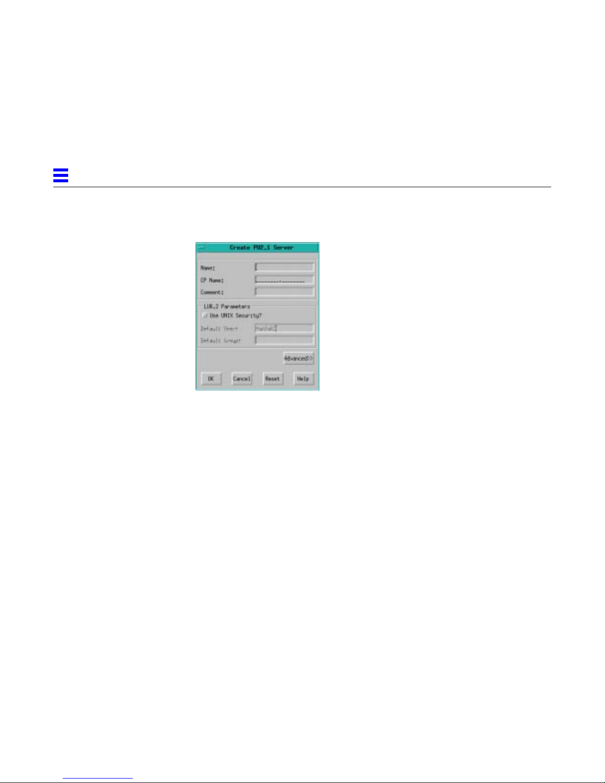
5
5.1 Basic PU2.1 Server Configuration
Name
The name of the server within the enterprise. The name can contain up to eight
alphanumeric characters (including @, #, and $). Tabs and spaces are not
allowed. The first character cannot be a number. You must specify the name of
the server. The name cannot be the same as any other PU2.1 server name.
CP Name
The name of the control point for the server. The format of the CP Name is
netid.netname, where netid is the SNA network ID and netname is the name of
the server within the SNA network. Each field can contain up to eight
alphanumeric characters (including @, #, and $). Tabs and spaces are not
allowed. The first character cannot be a number. Lowercase letters are
converted to uppercase. You must specify the name of the control point.
Comment
A free-form text area that you can use to further qualify and describe the
server configuration.
Use UNIX Security?
Indicates whether security for incoming attachments is verified against
information in the /etc/passwd database file. Check the box if you want to
verify the information. Clear the box if you do not want to verify the
information. This parameter is appropriate for APPC transactions only.
5-2 SunLink SNA 9.1 PU2.1 Server Configuration Guide—August 1997
Page 95
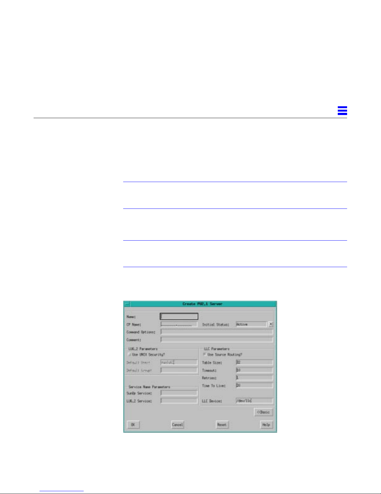
For more information, refer to Section G.5, “Unix-Level Security,” on
page G-5.
Default User
The user ID for remotely invoked APPC transaction programs. The default
value is sunlu62.
Note – You must add the Default User name manually (either sunlu62 or any
other name you specify) to the /etc/passwd database file. This parameter is
appropriate for APPC transactions only.
Default Group
The group ID for remotely invoked APPC transaction programs.
Note – If you specify a Default Group name, you must manually add it to the
/etc/group database file. This parameter is appropriate for APPC transactions
only.
5.2 Advanced PU2.1 Server Configuration
5
Configuring PU2.1 Servers 5-3
Page 96

5
Initial Status
Command Options
The initial status of the server when the system is initialized. The value can be
Active or Inactive. If you select Active, the server is automatically activated
when the system is initialized. If you select Inactive, you must manually
activate the server.
The command line options that you can use to customize the operation of the
server. Separate command line options with a space. The following table lists
valid command line options.
Table 5-1 Command Line Options
Option Description
-C Cause responses to be delayed until the Telnet client
has received the request. Used for Telnet
connections.
-F num_file_descriptors Set the number of file descriptors available to the
process. This is required if the number of client
connections exceeds the default number of file
descriptors for the platform.
-k keep_alive_type Send the keep_alive_type signal on Telnet client
connections. The value for keep_alive_type can be nop
or eor .
-L logfile_name Turn on Telnet client activity logging and set the file
to which data is logged to logfile_name.
-t trace_flag Enable SNA and Telnet tracing and set the type of
internal traces to capture in the trace file to
trace_flag. Sun recommends that you always set
trace_flag to -1, indicating all trace flags. Note that
you can also turn on tracing dynamically. For more
information, refer to Section 12.1.3.2, “Starting a
Line Trace,” on page 12-17.
-v Print the sunPU21 process version.
sunOP Service
The name of the TCP/IP service that the server uses when running the sunOP
troubleshooting utility. The service name must be in the NIS services database
or in the /etc/services database file.
5-4 SunLink SNA 9.1 PU2.1 Server Configuration Guide—August 1997
Page 97

LU6.2 Service
Use Source Routing?
Table Size
5
Note – If you are running multiple PU2.1 servers on the same system, the
SunOP service name must be unique for each server.
The name of the TCP/IP service that the server uses to provide the LU6.2
transaction program (TP) interface. The service name must appear in the NIS
services database or in the /etc/services database file.
This parameter is valid only when multiple LUType 6.2 servers are running on
the same system.
Indicates whether you want the software to perform Token Ring source
routing. Check the box if you want to perform source routing. Clear the box if
you do not want to perform source routing.
Use this parameter only when the server is operating over a LAN connection.
If you are using a platform driver that provides source routing, disable source
routing. For more information about IBM Token Ring network concepts, refer
to Appendix D, “IBM Token Ring Concepts."
The number of entries in the source routing table.
This parameter is valid only when source routing is enabled. Use this
parameter only when the server is operating over a LAN connection.
Timeout
The time, in seconds, to wait for a response to a source route determination
packet. The value can range from 1 to 30. The default is 10.
This parameter is valid only when source routing is enabled. Use this
parameter only when the server is operating over a LAN connection.
Retries
The number of attempts at on-ring then off-ring source route determination.
The value can range from 0 to 100. The default value is 1.
This parameter is valid only when source routing is enabled. Use this
parameter only when the server is operating over a LAN connection.
Configuring PU2.1 Servers 5-5
Page 98

5
Time To Live
LLC Device
The time, in minutes, to wait before discarding source route entries once the
route has been determined. The value can range from 1 to 1440. The default is
20.
This parameter is valid only when source routing is enabled. Use this
parameter only when the server is operating over a LAN connection.
The Unix pathname for the special file required for LLC.
Use this parameter only when the server is operating over a LAN connection.
5-6 SunLink SNA 9.1 PU2.1 Server Configuration Guide—August 1997
Page 99

Configuring Connections
This chapter contains the following sections:
• Adding a LAN Connection - describes how to add a Token Ring, Ethernet,
or FDDI connection.
• Adding an SDLC Connection - describes how to add a Synchronous Data
Link Control connection.
• Adding a QLLC Connection - describes how to add a Qualified Logical Link
Control connection.
6.1 Adding a LAN Connection
▼ To add a LAN connection:
1. Double-click PU2.1 Servers in the resource tree to display the name of the
PU2.1 server.
2. Using the right mouse button (MB3), click and hold the server name in
the resource tree and select New → LAN Connection from the popup
menu. The screen displays the Create LAN Connection dialog box.
6
3. Enter the appropriate information in the Basic dialog box and then click
4. To accept the settings, click OK. To exit a dialog box without accepting the
Advanced to display the Advanced dialog box. The following sections
describe the parameters in the Basic and Advanced dialog boxes.
settings, click Cancel. To return to the default settings, click Reset.
6-1
Page 100
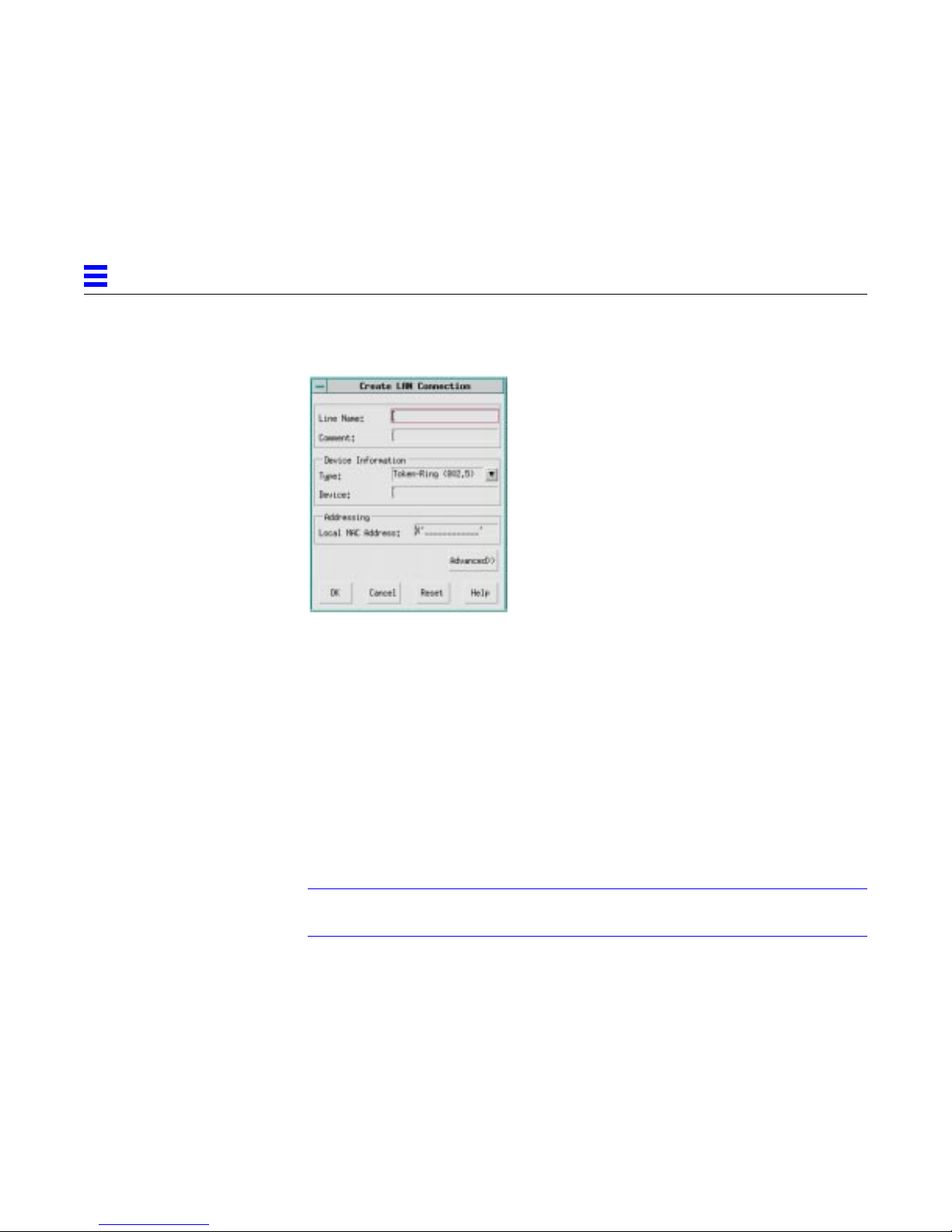
6
Line Name
6.1.1 Basic LAN Configuration
The name that identifies the LAN connection. The name can contain up to
eight alphanumeric characters (including @, #, and $). Tabs and spaces are not
allowed. The first character cannot be a number. You must specify name of the
connection. The name cannot be the same as any other connection name.
Comment
A free-form text area that you can use to further qualify and describe the LAN
connection. For example, you can use this parameter to specify the physical
location of the connection or the patch panel.
Type
The type of LAN connection. The value can be Token-Ring, Ethernet, or FDDI.
Note – Ethernet and FDDI connections are not supported on all platforms.
For more information, contact your Sun sales representative.
Device
The Unix pathname for the device-specific file for the LAN port.
An entry is required in this field. However, if you specify an appropriate
system type, a default device is automatically provided. For more information,
refer to Type in Chapter 4, “Configuring Systems."
6-2 SunLink SNA 9.1 PU2.1 Server Configuration Guide—August 1997
 Loading...