

Page 1

All the trademarks mentioned in this manual are registered property of SUN Telecom.
The right to interpret this manual is reserved by SUN Telecom.
User’s Manual
SUN-GE8100 Network Management System
Table: SUN-UM-FTTH-OLT001 Version: A/0
English
Page 2

Statement
Shanghai SUN Telecommunication CO., Ltd., all rights reserved.
Without the written permission of the copyright owner, any unit or individual shall not, in anyway, excerpt
copy or translate this manual.
Due to the constant renewal of products and technologies, the contents of the information may not
completely match the actual product, please understand. For inquiries on product updates, visit our Web
site: http://www.suntelecom.cn
Technical Support
Tel: 0086-21-60138638
Customer Service: [email protected]
Website: http://www.suntelecom.cn
Page 3

Introduction
Manual Instruction
This is <SUN Telecom EPON Network Management System Operation User‘s Manual>, this manual
is applicable to the EPON equipment with the SUN Telecom Network Management System. This
manual is used for equipment setting instruction. Please read me before operation.
Conventions
1. Command Description Convention
When this manual is introducing the usage of the commands, it might use one or several text format
as below to express particular description:
Format
Description
Bold
Refers to command line keyword (remain unchanged part of the command, must
input accordingly)
|
Used to separate several options, indicates that select from two or more options.
[]
Indicates that the content in the ―[]‖ is optional during command configuring.
[x|y|…]
Indicates that select one or not from two or more options.
<A.B.C.D>
Indicates that the user needs to input the IP address.
<A.B.C.D/M>
Indicates that the user needs to input the IP address, and it is allowed to
designate subnet mask with parameter ―M‖, ―M‖ is referred to the bit of the subnet
mask.
<n-m>
Indicates the allowable value range
2.Graphical Interface Convention
Format
Description
< >
―< >‖ indicates the button name, such as ―click <OK> button‖.
[]
―[]‖ indicates windows name, menu name and datasheet, such as ―pop up [open]
window‖.
/
Multilevel menu is separated with ―/‖, for example: [system/exit] indicates the [exit]
option under [system] menu list.
After this is explanative and illustrative content.
Page 4

→
The simple operation procedure is linked with―→‖, such as
―OLT→essentiainformation→enable‖, it means select OLT menu first, then the
essential information, and the click the enable button in essential information.
3.Content Introduction
Chapter
Content
Chapter 1 Product introduction
EPON product interview、features and introduction of network
management.
Chapter 2 Config the system
parameter of the network
management card
Change the IP address, Alarm address and system information
Chapter 3 EPON network
management software
Install, uninstall and enable the software
Chapter 4 EPON network
management software config
Network management software config, OLT config and ONU config.
Chapter 5 Bridge mode config
Bridge mode and config process
Chapter 6 Examples
Configuration examples
Page 5

Catalogue
Chapter 1 Product Introduction ................................................................................................... 1
1.1 Product Interview .......................................................................................................................................1
1.2 Interface and Indicator Light ....................................................................................................................1
1.3 Management Card Cable Connection ....................................................................................................2
2.1 Config Preparation ....................................................................................................................................3
2.2 Login Network Management Card Config .............................................................................................3
2.2.1 Telnet Login Network Management .............................................................................................3
2.2.2 Login network management by Console interface ....................................................................4
2.3 Config the System Parameter of Management Card ...........................................................................5
2.3.1 Command Format ..........................................................................................................................5
2.3.2 Config examples .............................................................................................................................5
2.4 Config Examples .......................................................................................................................................6
3.1 Installation...................................................................................................................................................7
3.1.1 Server...............................................................................................................................................7
3.1.2 Client ................................................................................................................................................7
3.2 Enable EPON network management software .....................................................................................8
3.3 Close EPON Management Software ......................................................................................................9
Chapter 4 EPON Network Management Software Config ....................................................... 1
4.1 Configuration Introduction ........................................................................................................................1
4.1.1 Login network management client ...............................................................................................1
4.1.2 Configuration Interface Introduction ............................................................................................1
4.1.3 Change User Password ................................................................................................................2
4.2 Basic Configurations .................................................................................................................................3
4.2.1 Add device .......................................................................................................................................3
4.2.2 Two ways to check .........................................................................................................................8
4.2.3 Update topology .............................................................................................................................9
4.2.4 Check the Device Rack ...............................................................................................................10
4.2.5 Description of the Device Icon ................................................................................................... 11
4.2.6 Alarm Management ...................................................................................................................... 11
4.3 OLT Configuration Management ................................................................................................................12
4.3.1 OLT Basic Information Management .........................................................................................12
4.3.2 OLT Config ....................................................................................................................................16
4.3.3 OLT Uplink Port Config ................................................................................................................18
4.3.4 OLT Bridge Parameter Config ....................................................................................................19
4.3.5 OLT Senior Management Config ...............................................................................................20
4.4 ONU Config ...............................................................................................................................................20
4.4.1 ONU Link Management ...............................................................................................................20
4.4.2 ONU Hardware Config ................................................................................................................21
4.4.3 ONU Config ...................................................................................................................................24
4.4.4 ONU 802.1x Management ..........................................................................................................31
Page 6

Fiber Op tic S oluti ons P rovider 1/31
Chapter 1 Product Introduction
1.1 Product Interview
iCoreView is a Sun TELECOM‘s independent R&D EPON Network Management System based on
SNMP V2c protocol, and it‘s compatible with SNMP V1. iCoreView adopts powerful management
capability; the staff in control center can monitor, manage and maintain EPON system in different places.
iCoreView made the network stable.
iCoreView provides operative and administrable interface, the features are:
Support Performance Management, Malfunction Management, Alarm Management, Safety
Management, and real time monitoring.
Provide reliable safety strategy, support multilevel user rights
Adopt hierarchical architecture, easy to operate
Support remote management and maintenance
Support several Trap management modes, support Trap Email distribution and Trap short
message notification, help the management staff know the condition of the device and the
network in time, ensure the stability of the network.
Perfect log management, record detailed log information during operation and maintenance,
ensure the safety of management and operation
Up-to-date edition supports Chinese and English
iCoreView adopts C/S architecture, composed of server and client
1.2 Interface and Indicator Light
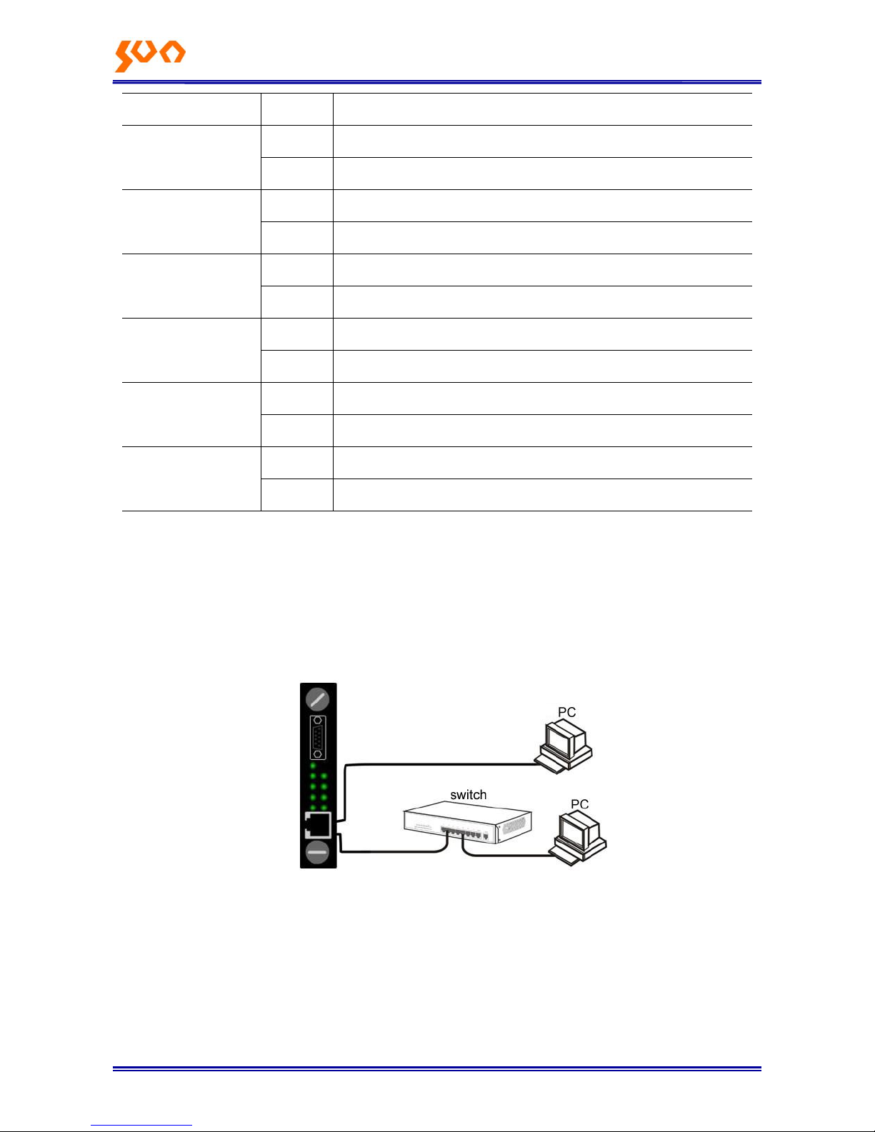
There is one RJ45 port and one Console port on the Network Management card, RJ45 port connects
with the PC network port, Console port connects with the PC Console port by serial line:
Table1-1 Indicator Light Status
Indicator Light
Status
Specification
RUN
Blink
The management card is normal
Off
The management card is not running.
FANA
On
The right power fan is normal
Off
The right power fan stops
FANB
On
The left power fan is normal
Page 7
Fiber Op tic S oluti ons P rovider 2/31
Off
The left power fan stops
PWRA
On
The right power supply is normal
Off
The right power supply is off
PWRB
On
The left power supply is normal
Off
The left power supply is off
FDX
On
The full duplex is on
Off
The half duplex is on
PWR
On
The power supply of the chassis is normal
Off
The power supply of the chassis is not normal
10M
On
RJ-45 port is under 10M mode
Off
RJ-45 port is under other modes
100M
On
RJ-45 port is under 10/100M mode
Off
RJ-45 port is under other modes
1.3 Management Card Cable Connection
The EPON management card should be in the leftmost slot of the chassis (3U), the cable connection is
shown as Figure 1-1, and both two connections in Figure 1-1 are OK.
Figure 1-1 Cable Connection between PC and Management Card
Page 8

Fiber Op tic S oluti ons P rovider 3/31
Chapter 2 Config the system parameter of the management card
2.1 Config Preparation
Supposed the user has inserted the management card in the right place of the chassis, and has finished
the cable connection. Before the config, the user‘s PC has to meet some basic config demand.
1.User PC
Operation system (Windows 2000/XP/Vista/Win7)
Install the management agent card
2.Establish correct network configuration
For local config, the IP address of the PC and EPON management card must be in the
same subnet; for remote config, the PC and EPON management card must be reachable
through router. The default IP address of EPON management card is: 192.168.0.88,
Mask is: 255.255.255.0
Connect the RJ45 ports of the PC and EPON management card by UTP cable or through
switch. After positive identification, power on the device.
2.2 Login Network Management Card Config
2.2.1 Telnet Login Network Management
Click ―start/run‖ of the PC, see the dialog box, and input telnet 192.168.0.88 in ―open‖, shown as Figure
2-1
Figure 2-1 Telnet Login
Click <OK>, see the Telnet login interface, shown as Figure 2-2, input the user name and the password
Page 9

Fiber Op tic S oluti ons P rovider 4/31
(for first login, input default username: root, password: snmpman), then push the enter button, enter the
telnet command line config interface, then see the command prompt , indicates
successful login.
Figure 2-2 Telnet Login Interface
EPON network management card allows only one user to login in the same time.
No operations would display on the screen when you input the password, just push enter key
after the input.
Push Ctrl+Backspace to delete; only Backspace wouldn‘t work.
2.2.2 Login network management by Console interface
It supports config the network management card by HyperTerminal if the card IP address is unknown.
Connect the Console port of the PC with the Console port of the management card with RS232 serial
line, and then run the HyperTerminal (start-program-accessories-communication-HyperTerminal) . Need
to input area code, phone number and other related information for the first login, and then click<OK> to
next step, input ‗SUN Telecom management card‘ in ―tag‖ under [connection description], click ―OK‖, to
[connect to…], click ―OK‖, to [properties], click <restore to default>, then select 115200 in ―bit per
second‖, click ―OK‖, then to [hyperterminal], input enter, see the .
Page 10
Fiber Op tic S oluti ons P rovider 5/31
2.3 Config the System Parameter of Management Card
2.3.1 Command Format
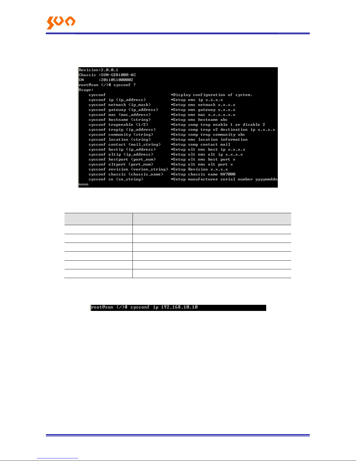
Use sysconf to show the system basic information; use sysconf ? to see the help information as below:
The primary command format of management card is shown as Table 2-1:
Command format
Description
sysconf
Show system basic information
sysconf ip
Config agent card IP address
sysconf trapip
Config agent card alarm address
sysconf trapenable
Enable the alarm function
sysconf info
Config the system information
reboot
Reboot the agent card
OLT host ip should not be in the same network segment. Eg, default host IP is 192.168.1.100, in the 在
192.168.1.× network segment; for agent card IP is 192.168.0.88, in 192.168.0.× network segment.
2.3.2 Config examples
Config the agent card IP address: 192.168.10.10, alarm address: 92.168.10.11; as below:
In config windows: Input sysconf net and push enter
Display IP address: Input the IP address and push enter
Display Net mask: Input subnet mask and push enter
Display Gateway: Input gateway and push enter
After the prompt message, input y and push enter to change the Host name..
Host Name Config:
In config windows: Input sysconf host and push enter
Display Host name: Input the name and push enter
After the prompt message, input y and push enter to change the Host name..
Page 11

Fiber Op tic S oluti ons P rovider 6/31
Trap config
In config windows: Input sysconf trap and push enter
Display Trapenable: Input 1 or 2 and push enter, 1 for enable, 2 for disable
Display Trapsink: Input the first trap address and push enter
Display Trap2sink: Input the second trap address and push enter
Trapcommunity: Input trap type and push enter, it is snmptrap here
After prompt message, input y and push enter to change the trap address
System Information Config:
In config windows: Input sysconf info and push enter
Display Syslocation:: Input the address info and push enter
Display Syscontact: Input the contact and push enter
After the prompt message, input y and push enter to change the info
In prompt message, y stands for OK and save, n stands for cancel.
Restart the management card to enable the config
2.4 Config Examples
Config the IP address: 192.168.10.10, Net mask: 255.255.255.0; Gateway: 192.168.10.1; Trapsink:
192.168.10.11; Other info: default. Enter telnet or Console windows, the config process is shown as
Figure 2-3:
Figure 2-3 Config Process
After config, input reboot and push enter to restart the management card, and then config would be
enabled after the restart.
Page 12

Fiber Op tic S oluti ons P rovider 7/31
Chapter 3 EPON Network Management Software
3.1 Installation
The EPON management software is a compressed file.
1. There is disk will be sent together with the EPON products. The EPON software EPON_2.0.0.7.rar
( , 2.0.0.7 is the version) is in the disk, decompress it. The install path should
be English, no Chinese. After decompression, there is below contents in the objective directory:
MySQL5 is the folder for mysql database
Client is the folder for client end
Server is the folder for the server
Operating Instructions.txt is the introduction of installation
2. Install MYSQL database. It is convenient to install MYSQL, we supply an automatically installation
programme regmysqlservice.exe, after decompression, users can find this programme under the
directory of MYSQL5, users just need to run one time the MySQL5\regmysqlservice.exe, then the
MYSQL data base is installed successfully. Then EPON software is installed successfully.
3.1.1 Server
EPON management server supports to collect the information of the OLT racks, and centralized
supplying services to the user ends.
3.1.2 Client
Client end supports to manage the OLT cards and ONUs, detail functions as below:
User management: add, delete and modify users. Set different authorities to different users,
so to implement decentralized management to the users.
Agent management: add the agent information of the rack, so to browser the operating
information of the rack and the alarm information.
Page 13
Fiber Op tic S oluti ons P rovider 8/31
Alarm query: set the agent card TrapLInk pointing to server IP address, all the login server
client can get the current alarm information, and check the history information.
Device management: manage OLT cards and ONUs
Alarm management: manage history alarm information and use current alarm information to
cut the network operating status.
3.2 Enable EPON network management software
EPON network software consists of server and client, before using the client; need to enable the server
firstly.
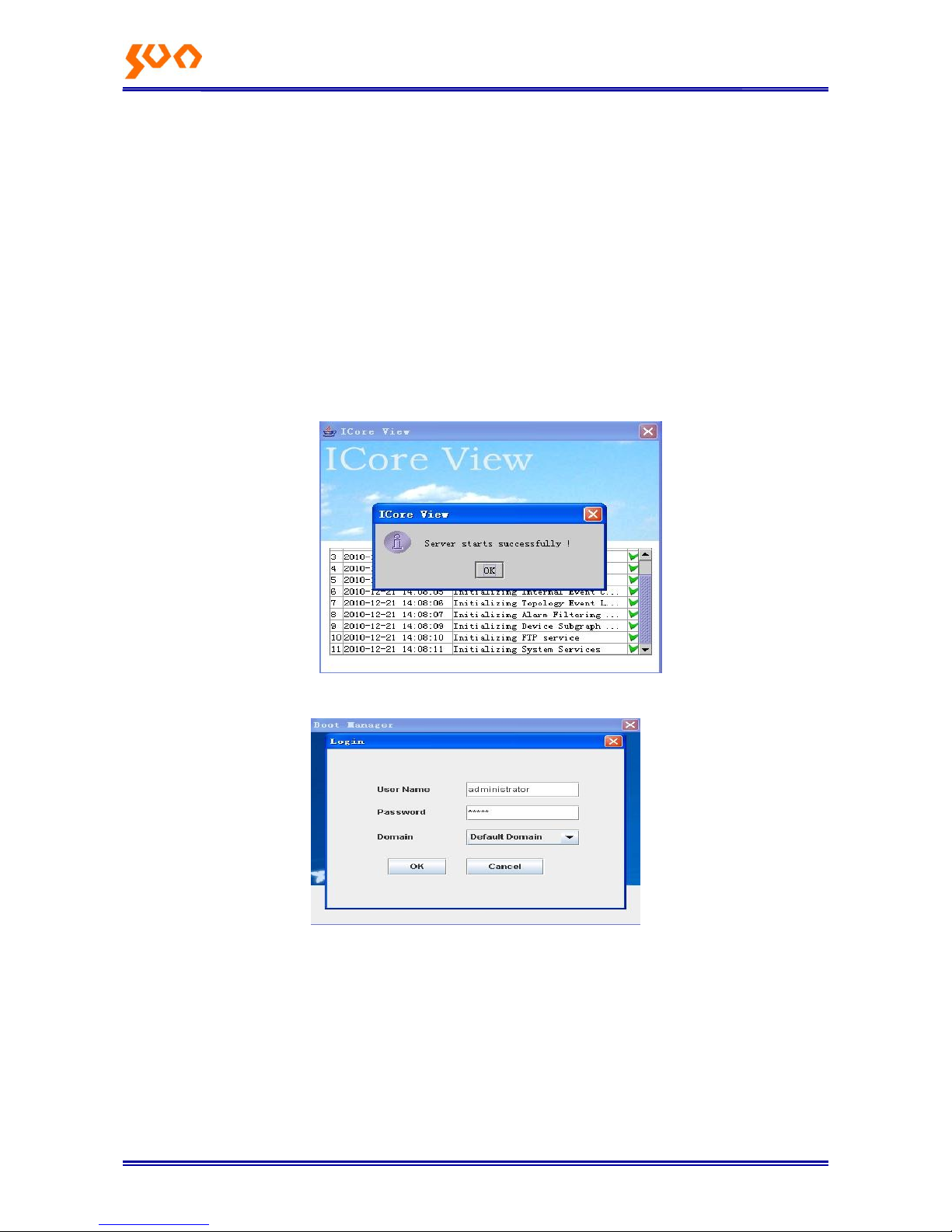
Enable the server: run server\RunServer.exe
Enable the client: run client\MainClient.exe, input password: admin, click OK
Page 14
Fiber Op tic S oluti ons P rovider 9/31
3.3 Close EPON Management Software
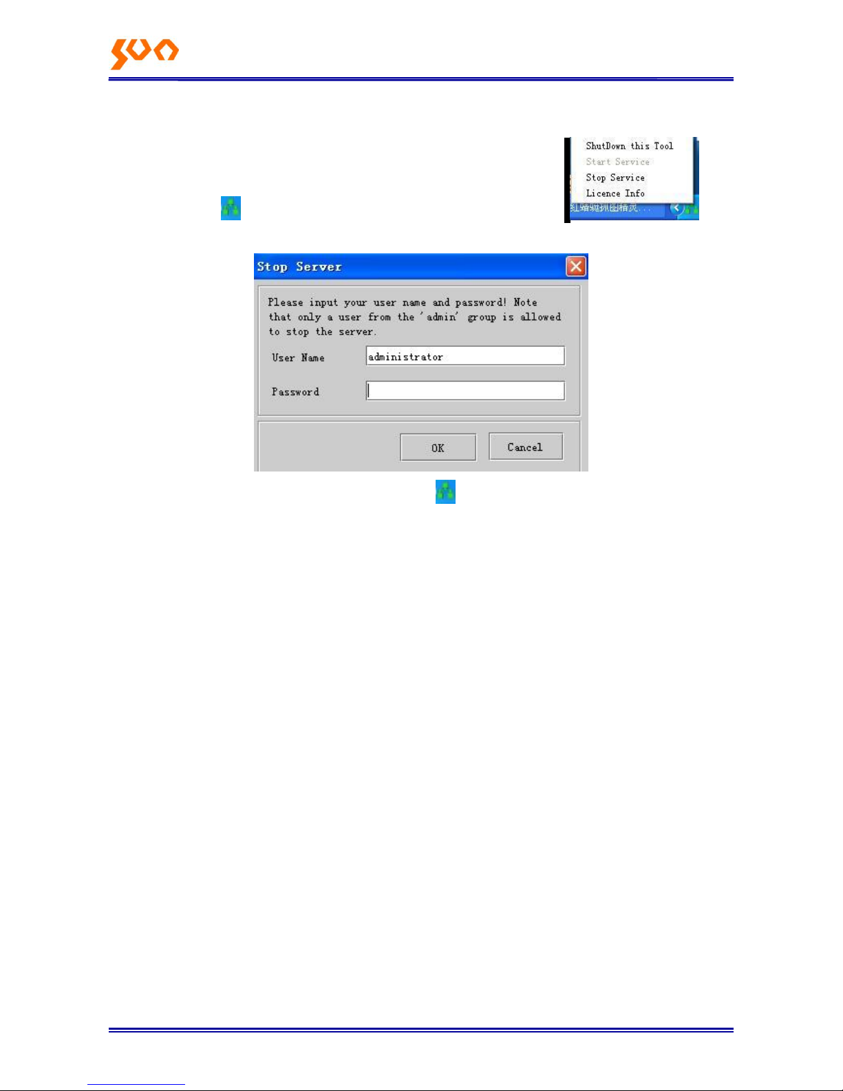
Left click the icon at the right Conner of the PC, choose ―Stop Service‖ , then
you will see the below interface:
Input password ―admin‖, click ―OK‖. Left click the icon again, choose ―ShutDown this Tool‖, then the
software closed.
3.4 Uninstall EPON Management Software
1. Close EPON client and server
2. Run MySQL5\DelMysqlServer.bat to uninstall the MYSQL database
3. Delete all the EPON management software files
Page 15
Chapter 4 EPON Network Management Software Config
Users can use EPON SNMP software to manage and maintenance the devices directly; install and
enable the device please refer to the Chapter 3.
Before config any items, please make sure the connection between the PC and the agent is correct,
and configure the agent IP address and alarm address (there is default IP existed) correctly through
Telnet or Console port. There is LED description refer to the connections (check table 1-1) .
4.1 Configuration Introduction
4.1.1 Login network management client
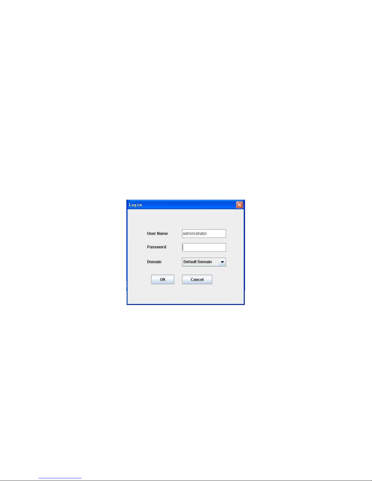
Enable the software according to 3.2, see as Figure 4-1, there is prompt about input account and
password (there is default account name existed—administrator, password: admin. Click OK, enter the
network management interface.
Figure 4-1 Login Interface
4.1.2 Configuration Interface Introduction
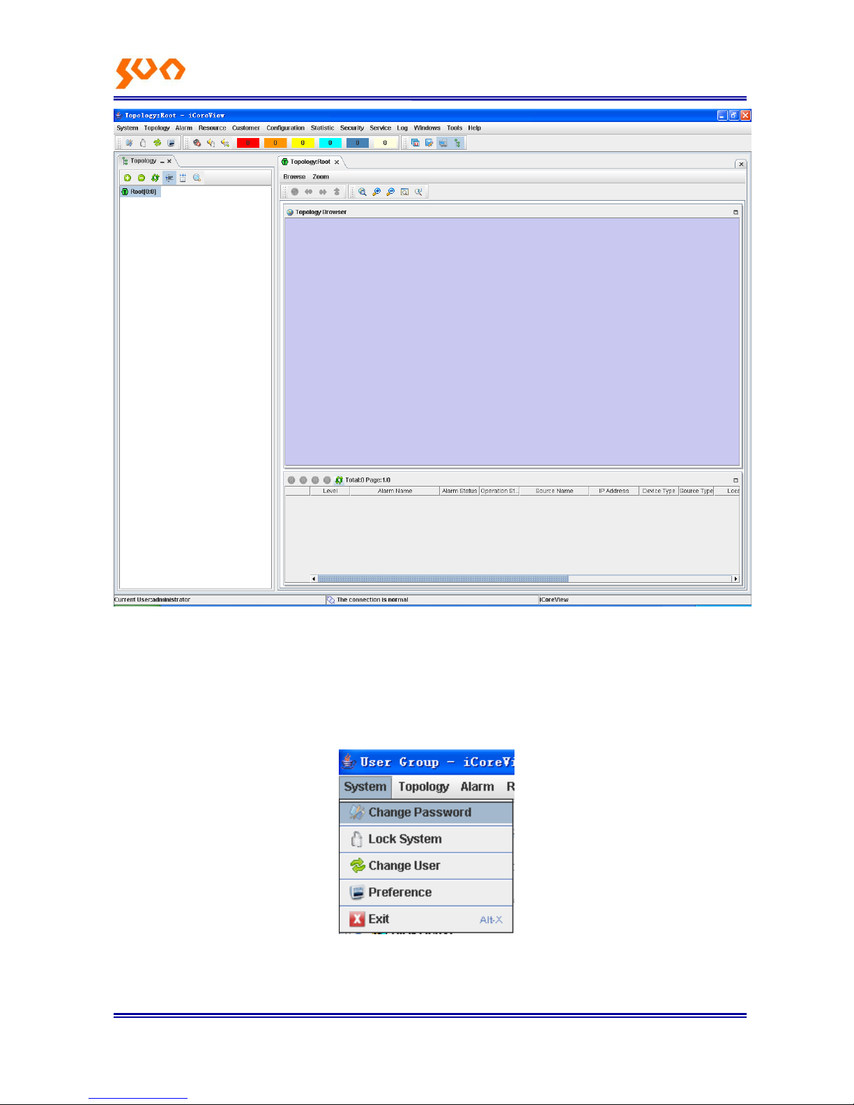
First login; see as below Figure 4-2:
Page 16
Fiber Op tic S oluti ons P rovider 2/31
Figure 4-2 First Login
4.1.3 Change User Password
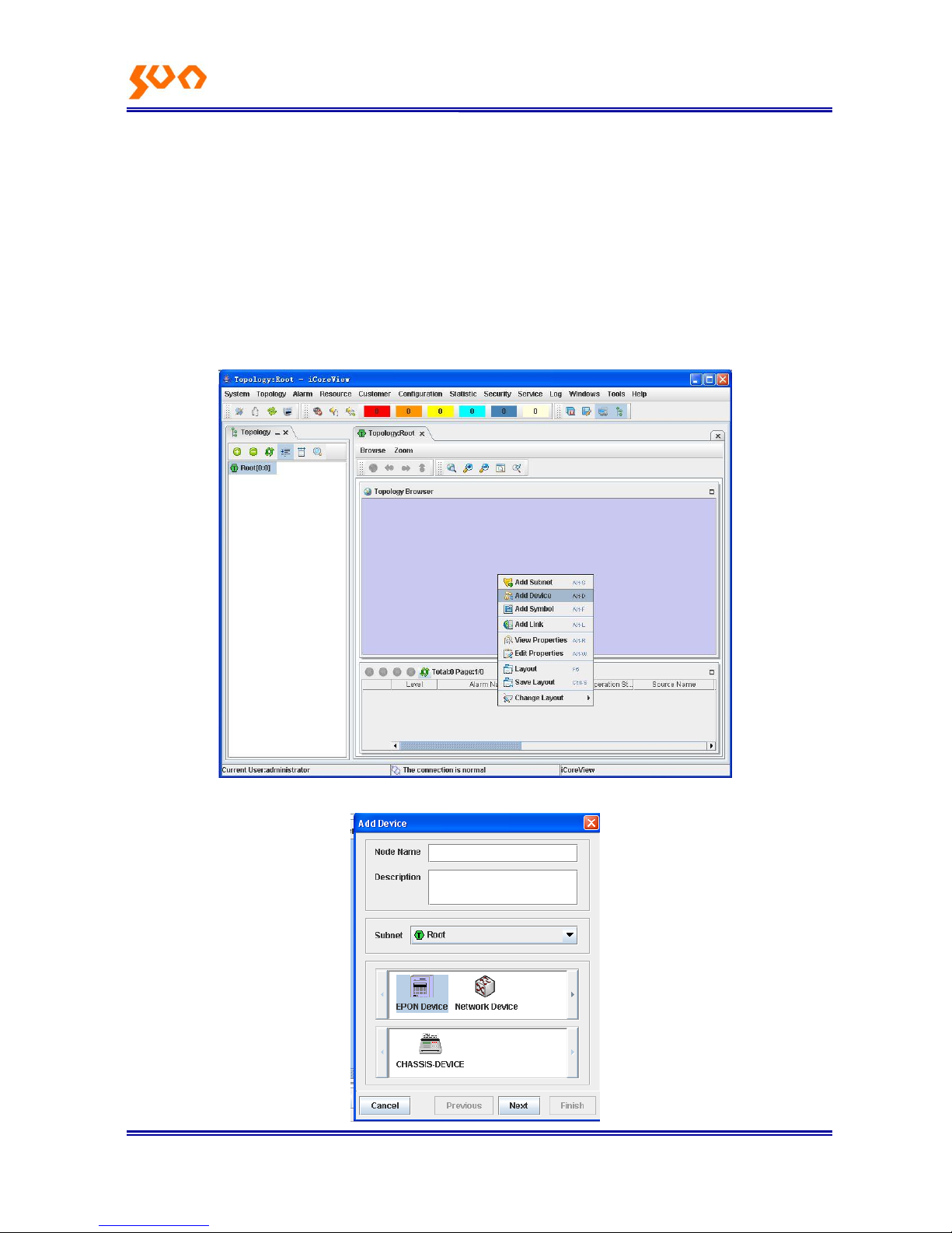
Enter the configuration page, left click the main menu【System】-->【ChangePassword】 as Figure 4-3,
to change password.
Figure 4-3 change password
Administrator can add user groups or users, delete users, change user password and distribute
Page 17
Fiber Op tic S oluti ons P rovider 3/31
resource, details refer to the main menu【Help】‖chapter 8‖
4.2 Basic Configurations
4.2.1 Add device
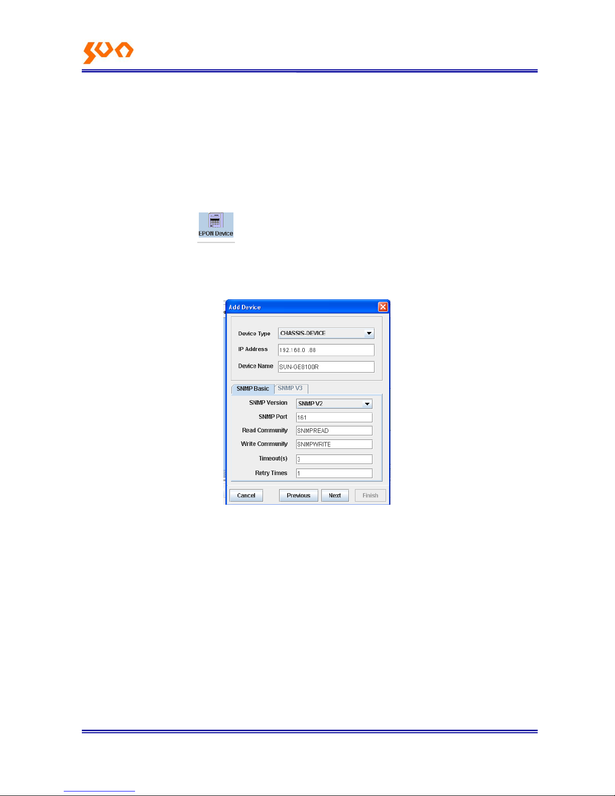
After enter the Figure 4-2 interface, need to add a device node, follow as below:
In the topology browser, or choose a subnet in the topological view, right click the mouse, choose ―Add
Device‖, see as Figure 4-4. then popup the add device dialog box as Figure 4-5.
Figure 4-4 Add device
Page 18
Fiber Op tic S oluti ons P rovider 4/31
Figure 4-5
This page includes the below properties:
Node Name: necessary. The name of the node, this name displays in the topological view.
Node Description: optional. Descript the node, not display in the topological view.
Subnet: necessary. The subnet the node located, default is present subnet.
Icon: necessary. The icon the node uses.
Click the EPON Device icon, There are the manageable devices list supplied by SUN
Telecom, then click the related EPON device. Here taken SUN-GE8100 as an example.
Click ―Next‖, enter next property editing page. As Figure 4-5.
Figure 4-6
This page includes below properties:
Device type: necessary. The types of the devices, just for display, can‘t be revised.
IP Address: necessary. Device IP addresses, default IP is 192.168.0.88, and users can
change the IP and then do configurations.
SNMP Basic: optional. SNMP management properties, includes: version, SNMP port, read
and write community, time out config and retry times, there is default value at initial. When
choose SNMP version V3, ―SNMP V3 property‖ page is available, users can config V3
properties, including user name, security class, authentication protocol, authentication
password, private agreement, and private password.
Page 19
Fiber Op tic S oluti ons P rovider 5/31
Some properties in this page (SNMP version, SNMP port, read community, write community),
we have config default value. User can revise it according to real environment. Users just fill
the IP address is enough to use.
After fill the properties, click ―Next‖, enter next property editing page, as Figure 4-6.
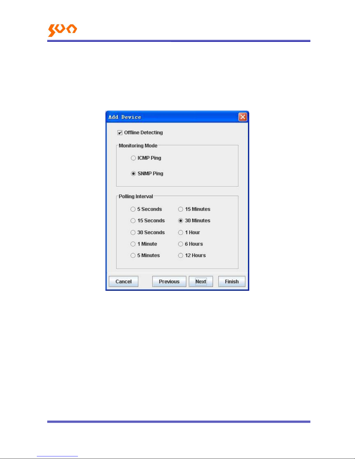
Figure 4-7
This page includes below properties:
Offline Detecting: if there is off link detecting to the devices.
Monitoring Mode: adopt which operation, There are two options: ―ICMP Ping‖ and ―SNMP Ping‖.
Polling Interval: the interval time the system polling operations to devices, there are several optionas:―5
seconds‖, ―15 seconds‖, ―30 seconds‖, ―1 minute‖, ―5 minutes‖, ―15 minutes‖, ―30 minutes‖, ―1 hour‖, ―6
hour‖, ―12 hour‖
Use default configuration is enough. If 30 minutes polling interval is too long, users can choose a short
time like 5 seconds, 15 seconds or 30 seconds, the software can get the online and offline status in
time.
After configure, click ―Next‖, and enter another property editing page, as Figure 4-7.
Page 20
Fiber Op tic S oluti ons P rovider 6/31
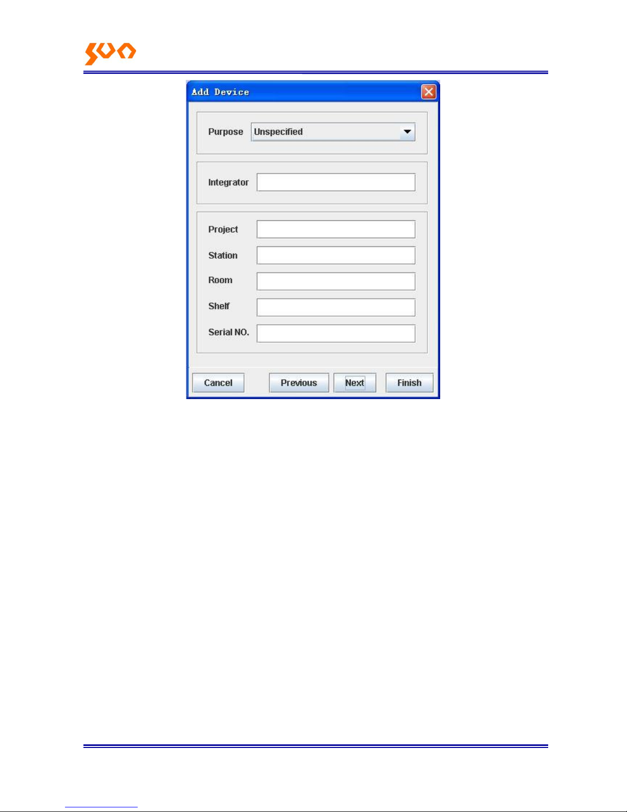
Figure 4-8
This page includes below properties:
Purpose: necessary. Identify the device is access layer device or integrated layer device;
Integrator: optional. Device integrator.
Project: optional. The project where the device use
Station: optional. The station where the device use
Room: optional. The machine room where the device use
Shelf: optional. Serial Number of the shelf.
Serial NO: optional. The device capitol serial number.
This page can use the default configuration, supporting user-defined.
After configuration, click ―Next‖, enter next property editing page.
Page 21
Fiber Op tic S oluti ons P rovider 7/31
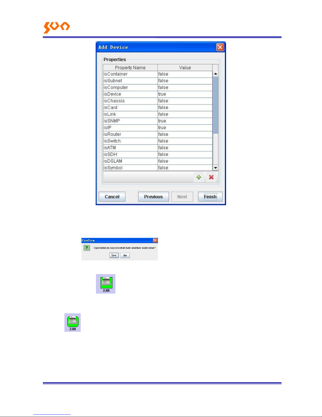
Figure 4-9
Please don‘t revise the property of this page, keep the default ones.
After configuration, click the ―Finish‖ button to implement creating device node operation, if success,
there is prompt ―operation is successful, Add another node now?‖
Choose ―yes‖, the wizard automatically switches to the first page; choose ―No‖, the dialog box closed.
Adding a device node in the topological view, if the device properties filled correctly, and the
device is online, the management software will collect the device basic information, and producing
topological structure according to the device. The icon of the device will change from rectangle to round
rectangle in 5 seconds. Expand the left tree topological structure you can see the device
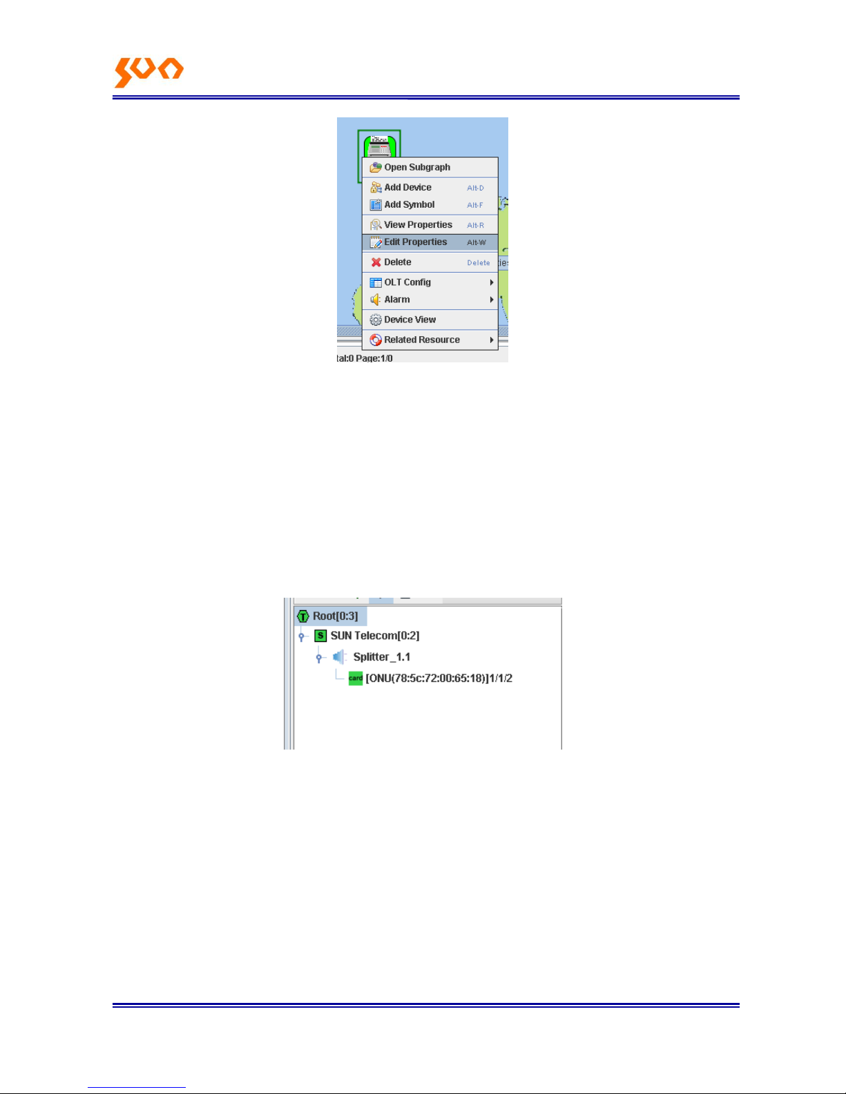
topological situation.
After adding devices completed, you can revise the device properties. Right click the device icon, and
choose 【Edit Properties】, as Figure 4-10.
Page 22
Fiber Op tic S oluti ons P rovider 8/31
Figure 4-10
The configuration property wizard comes up. This wizard is the same with the former adding device
wizard.
Users can revise the properties according the real needs.
4.2.2 Two ways to check
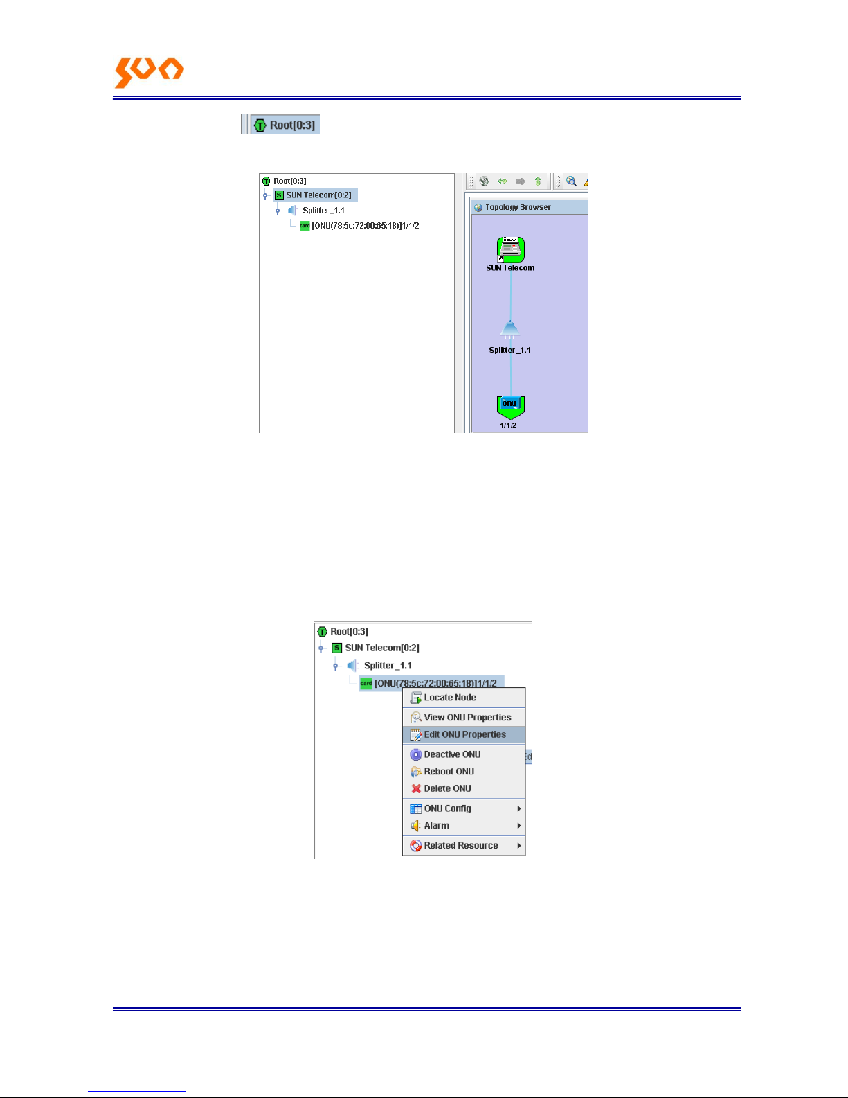
1. Expand the left tree topological structure, as Figure 4-11.
Figure 4-11
There are two registered ONUs under an OLT, if there is no ONU connects to the OLT, you can‘t see
the topological structure. If there is ONU connected, but no topological structure, check if the ONU
register successfully (ONU LLID keep lit when register successfully) .
【78;5c:72:00:65:18】 is ONU MAC address, 【4/1/1】is ONU index, 【4】represents OLT is at the fourth
slot of the rack, the first【1】represents the first PON port of the OLT, the second【1】means the ONU
is the first ONU under this OLT.
Page 23
Fiber Op tic S oluti ons P rovider 9/31
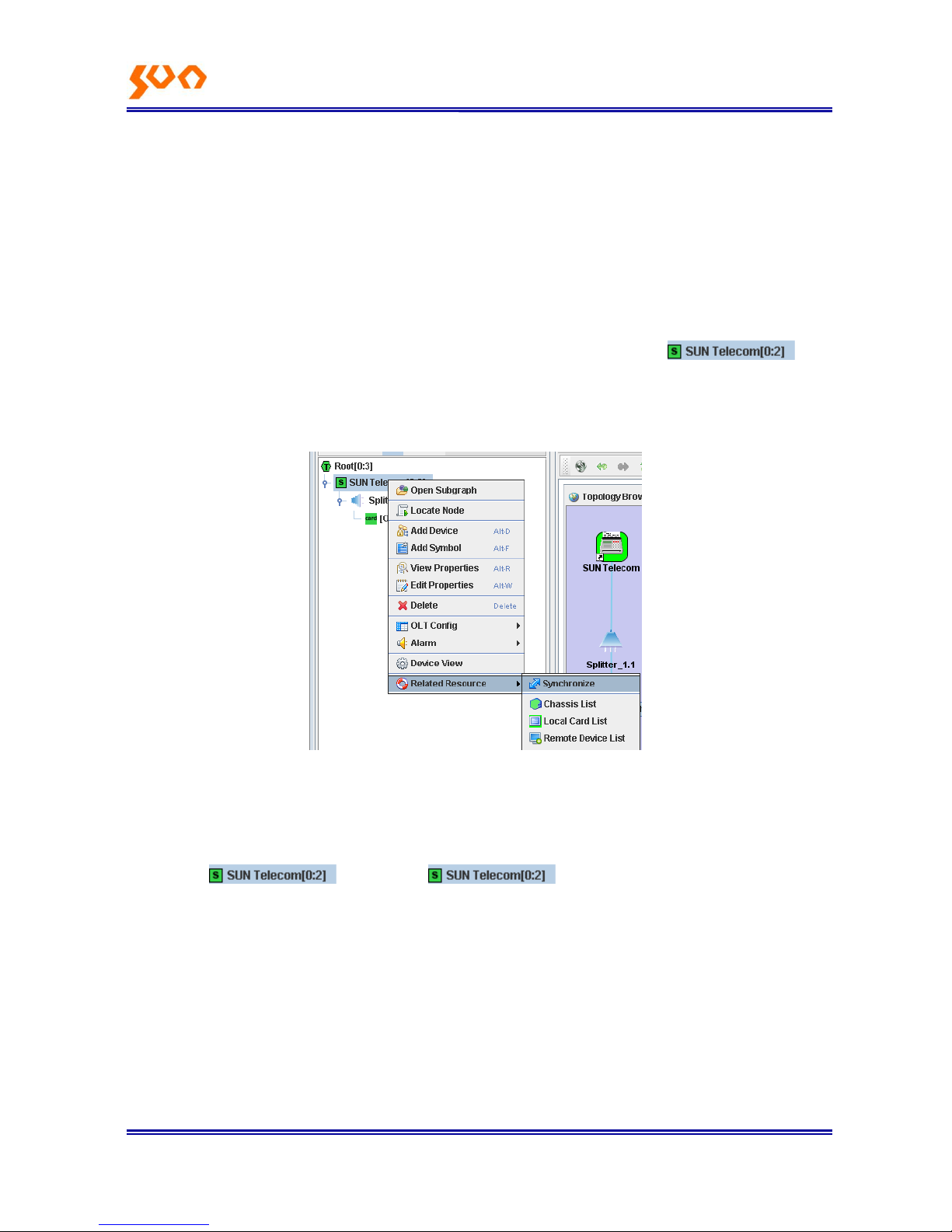
2. Right click the icon and choose【Open Subgraph】, check the device topological view as
Figure 4-12.
Figure 4-12
Users can revise the ONU properties (name and description information; After uses adding device, the
management software will automatically produce the device topological structure, there is a default
name and empty description information produces, users can edit it according to the real
requirements.) . Right click the ONU icon and choose 【Edit ONU Properties】, as Figure 4-13, then
users and edit the properties. When revising the ONU name, we suggest reserving the index.
Figure 4-13
4.2.3 Update topology
The way to update the topology is to perform resource synchronization operations. Resource
Page 24
Fiber Op tic S oluti ons P rovider 10/31
synchronization refer to: The status of the managed devices, cards, ports (these called resource) in the
software be synchronized with the real devices status. When receiving TRAP alarm host IP is set as the
server IP address (the way to set the EPON device receiving TRAP alarm host IP, refer to the chapter
2.2.2 example), the server can update the device real-time status according to the TRAP alarm
information from the devices. This reflection costs some time, manual operation supported to
implement this update operation.
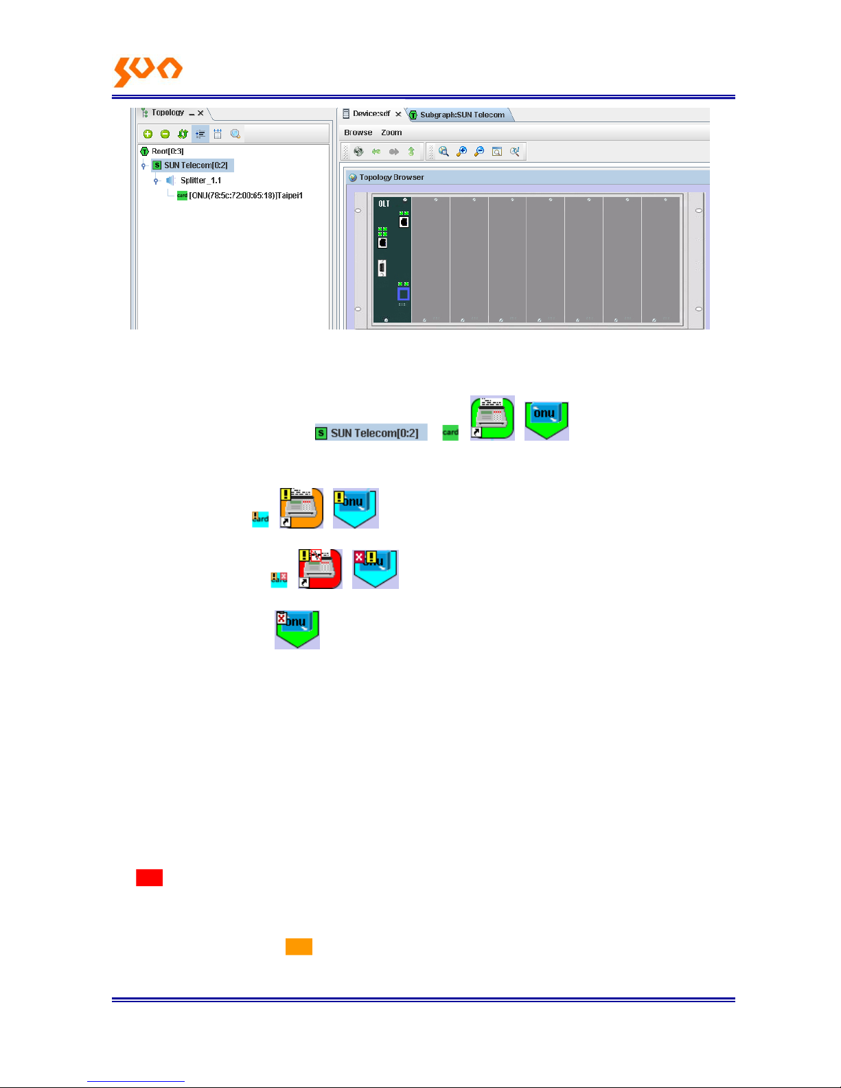
Check the Figure 4-14, right click the devices need to configure synchronization ,
and choose 【Related Resource】-->【Synchronize】. The system performs this operation costs some
time (the need time depends on the network status and the devices, usually 3 to 8 seconds)
Figure 4-14
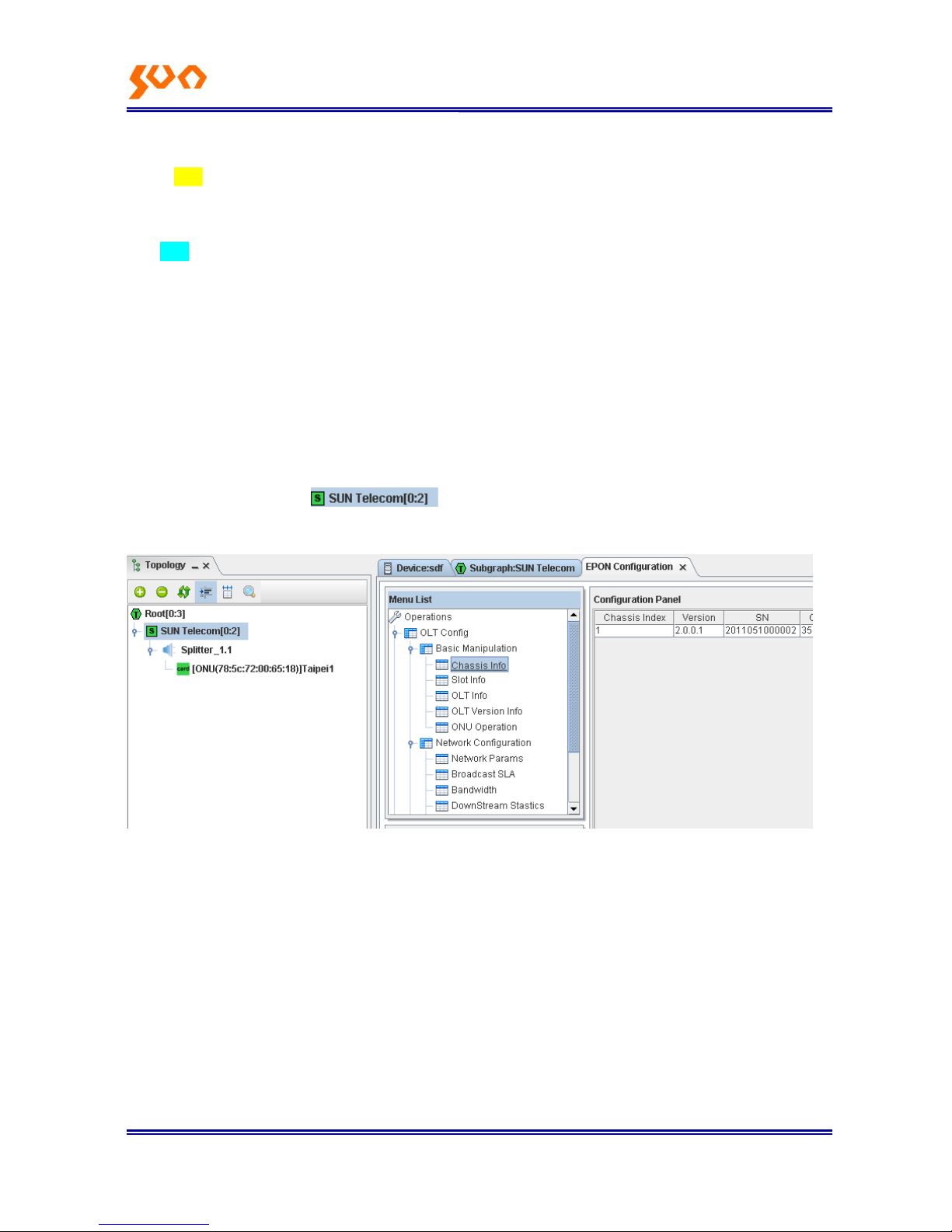
4.2.4 Check the Device Rack
Double click or right click , and choose【Device View】 to check
the device rack status, as Figure 4-15.
Page 25
Fiber Op tic S oluti ons P rovider 11/31
Figure 4-15
4.2.5 Description of the Device Icon
If there is no mark on the icon like , , , , it resents the devices
work normal, OLT and ONU are online.
If there is ―!‖ such as , , , it means there is alarm on this device.
If there is red ―×‖ such as , , , it means the device offline.
If there is white ―×‖ such as , it means ONU was refused to access.
4.2.6 Alarm Management
Telnet to the agent card, set the alarm IP address as the PC IP address (where the server is), configure
as the introduction in Chapter 2.2.
For every type of alarm event, iCoreView system marks them with a level to show it severity. View NNM
provides 5 levels in all, from the most serious to the least serious, they are:
Critical Alarm (Critical): The highest level alarm, which will interrupt the communication. Marked in
red: .
Major Alarm (Major): Service continues while the performance declined considerably and affected the
operation. Marked in orange:
Page 26
Fiber Op tic S oluti ons P rovider 12/31
Minor Alarm (Minor) :Alarm event occurs but do not affect the operation of the service. Marked in
yellow:
Warn Alarm (Warn) :The service is operating in order. Only an ordinary problem occurred. Marked in
blue:
Unknown Alarm (Unknown): Alarm events that can not be recognized. Marked in light grey.
Details introduction please refer to the main menu【Help】Chapter 5.
4.3 OLT Configuration Management
4.3.1 OLT Basic Information Management
Right click the device icon and choose【OLT Config】-->【Basic Manipulation
Classic Info】-->【Classic Info】, then popup the OLT SNMP config interface, as Figure 4-16.
Figure 4-16
Left EPON configuration page is a tree function list, below the list are the devices it support, right side is
a configuration panel to display the device information and the configuration options.
Example:
Check or revise the OLT【Bridge Parameter】
Choose 【OLT Config】-->【Bridge】 -->【Bridge Parameter】, right side will display the parameter as
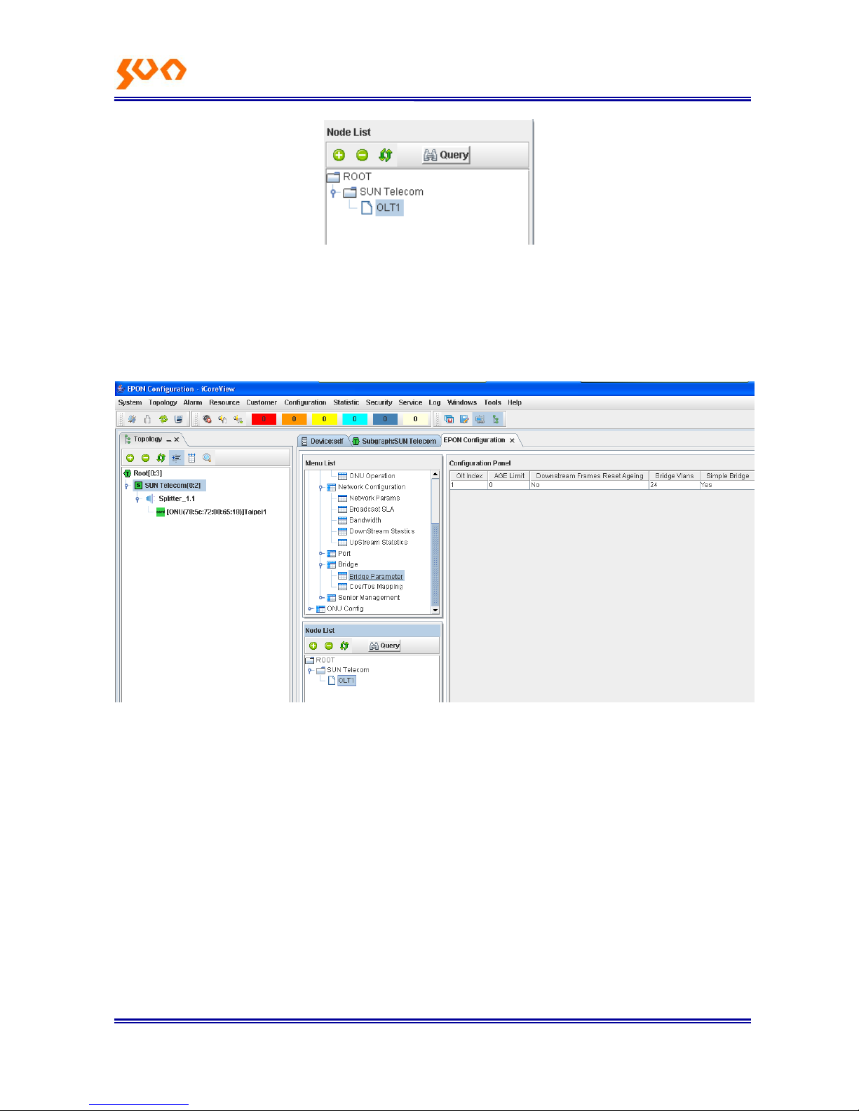
Figure 4-15. If there is no information for【Bridge Parameter】, that means it didn‘t point to the OLT in the
left device list. Click an OLT in the list as Figure 4-17.
Page 27
Fiber Op tic S oluti ons P rovider 13/31
Figure 4-17
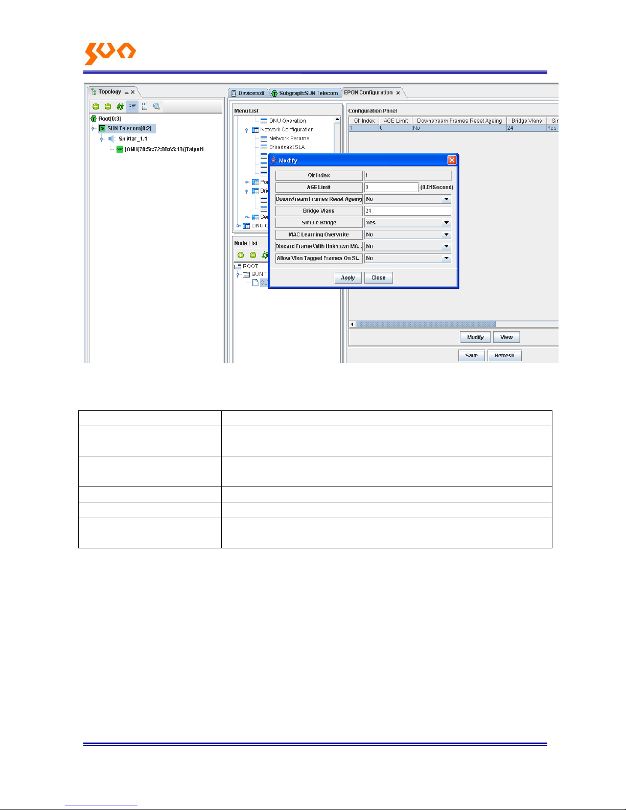
Click the 【Bridge Parameter】 again, the right list will display the OLT bridge parameters, as Figure
4-18.To revise the bridge parameter, needs to click the row firstly, then click【Modify】, revise the
parameters in the popup dialog box, after revise, click apply. As Figure 4-19.
Figure 4-18
Page 28
Fiber Op tic S oluti ons P rovider 14/31
Figure 4-19
OLT basic function information description, as table 4-1.
Menu
Function Description
【class Info】
Check the rack information, includes rack temperature, power status,
fan speed
【Slot Info】
Check the slots information, support to implement restore and reboot
operations to the OLT in the slots.
【OLT Info】
Set the authentication mode to ONU
【OLT Version Info】
Check OLT software version, hardware version
【ONU Operation】
Check the ONU status under the OLT, implement add, delete and revise
operations to the ONU
Table 4-1
【Slot Info】
This menu includes two functions:
Restore OLT to factory settings; when OLT can‘t communicate to all the ONUs, try this operation;
Reboot OLT;
Note: After restore OLT to factory settings, need to reboot OLT, then operation effects.
【OLT Info】
Set the registration mode to ONU; The authentication mode includes: accession, MAC and sn, default
Page 29

Fiber Op tic S oluti ons P rovider 15/31
one is accession. There are three operations under the three modes: Undefined, Allow and Deny, these
can manage the ONU access.
Accession: under this mode, ONU can register normally and display in the topological view. Choose
Deny operation, ONU can‘t communicates with OLT; choose Undefined or Allow, ONU can
communicate with OLT; default is Undefined, when new ONU access, it can communicate with OLT.
Mac: under this mode, ONU can register normally and display in the topological view. Choose
Undefined or Allow, ONU can‘t communicate with OLT; default is Undefined, when new ONU access, it
can‗t communicate with OLT.
Sn: this mode has no effect.
【ONU Operation】
Set ONU access mode, there are three modes: Undefined, Allow and Deny, as Figure 4-20. Users can
config according to real requirements.
Figure 4-20
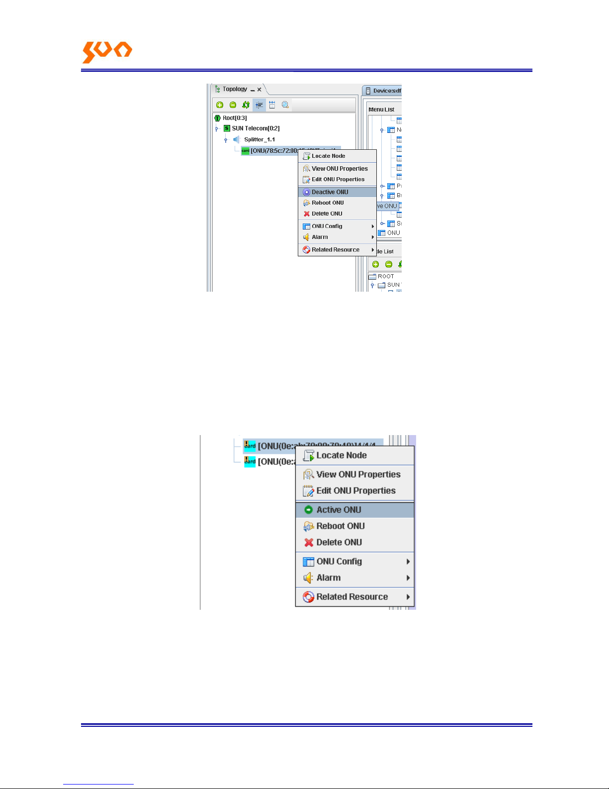
Users can config ONU in the tree topology, as Figure 4-21.
Page 30
Fiber Op tic S oluti ons P rovider 16/31
Figure 4-21
Right click ONU, choose 【Deactive ONU】, the access mode changes to Deny, communication
between ONU and OLT break off. If choose【Active ONU】, ONU access mode changes to Allow, ONU
communicate normally with OLT, as Figure 4-22
.
Figure 4-22
4.3.2 OLT Config
Click OLT, (【OLT Config】-->【Network Configuration】), config menu as Figure 4-23, function description
Page 31

Fiber Op tic S oluti ons P rovider 17/31
as Table 4-2.
Figure 4-23
Menu
Function Description
【Network Params】
Revise the VLAN Ethernet type passing through OLT (suggest use the
default value 8100), add tags to uplink and downlink (suggest not config
this)
【Broadcast SLA】
Config the OLT SLA downlink broadcast bandwidth
【Bandwidth】
Config the maximum upstream and downstream bandwidth of OLT PON
【DownStream Stastics】
Check the OLT downstream spastics
【UpStream Stastics】
Check the OLT upstream stastics
Table 4-2
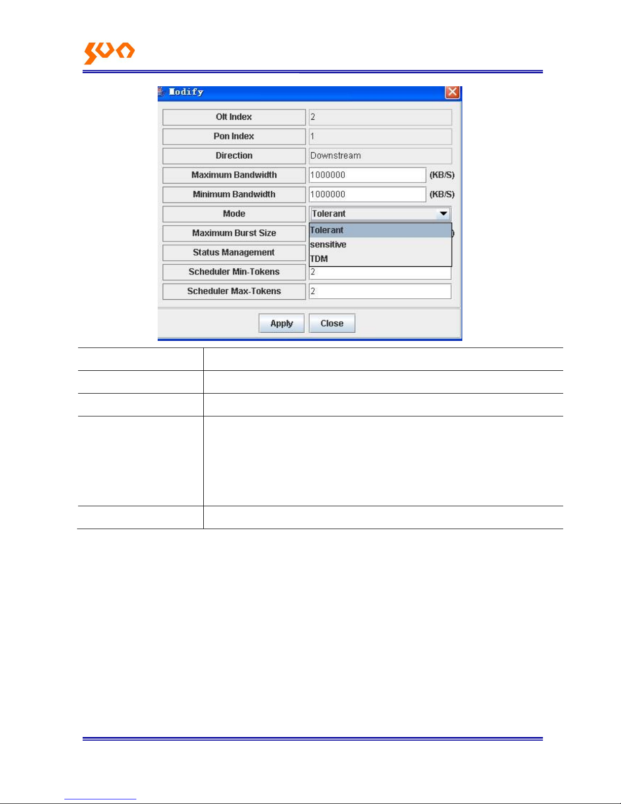
【Broadcast SLA】detail functions refer to table 4-3.
Page 32
Fiber Op tic S oluti ons P rovider 18/31
Menu
Function Description
【Maximum Bandwidth】
Maximum data transmission rate
【Minimum Bandwidth】
Minimum data transmission rate
【Mode】
Sensitive: distribute a fixed bandwidth to the link, let the link data queue empty
Tolerant: only when the link data queue is empty, the bandwidth allocated to the
link is virtual value (recommend this mode)
TDM: time division multiplexing, supports to set the size of round time slice
【Maximum Burst Size】
Maximum bandwidth reserved for burse flow
Table 4-3
4.3.3 OLT Uplink Port Config
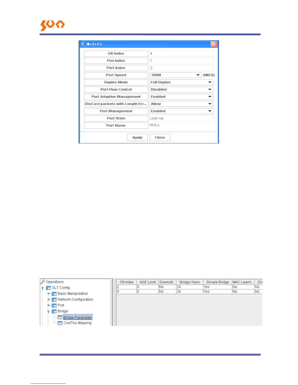
【OLT Config】-->【Port】-->【Uplink Port】, config as Figure 4-24.
Page 33
Fiber Op tic S oluti ons P rovider 19/31
Figure 4-24
Port speed: set port speed
Duplex Mode: set port working mode to full duplex or half duplex
Flow Control: enable or close 802.1x flow control
Port Adaptive Management: choose port adaptive mode, default is enable
Discard Packets with Length Errors: such as small data packet
Port Management: close or open the port, close the port, this port not work
Note: to config Port speed or Duplex Mode, must Disabled Port Adaptive Management firstly.
4.3.4 OLT Bridge Parameter Config
【OLT Config】-->【Bridge】, config menu as below Figure 4-25。
Figure 4-25
【Bridge Parameter】
Page 34

Fiber Op tic S oluti ons P rovider 20/31
AGE Limit: set OLT aging time, default is no configuration
Downstream Frame ResetAging: Reset aging to downstream frame, this configuration effects to all the
MAC table entries.
Simple Bridge: default is enabled
MAC Learning Overwrite: overwrite the entries in the MAC address table
Discard Unknown MAC Addresses: discard unknown MAC, not flood
Allow VLAN Tagged Frames on Simple Bridge: allow data frame with VLAN transmitting in Simple
Bridged link, default config is not enabled; to config VLAN, need to enable this function first.
4.3.5 OLT Senior Management Config
【OLT Config】-->【Senior Management】, introduction as table 4-4.
Menu
Function Description
【Dynamic MAC】
Check the learned Dynamic MAC from OLT link
【Static MAC】
Config the Static MAC bond to OLT link
Table 4-4
4.4 ONU Config
SUN-GE8200 series ONU includes: SUN-GE8200 one port 100M ONU, SUN-GE8200G one port
Gigabit ONU, SUN-GE8200D two ports with 100M and 1000M ONU, SUN-GE8204 four 100M ports
ONU, SUN-GE8208 eight 100M ports ONU. In the management system, there are two ports for
SUN-GE8200G ONU and SUN-GE8200 ONU. SUN-GE8200G port correspond to the port index 1, port
2 is not used; SUN-GE8200 port correspond to port index 2, port 1 is not used; SUN-GE8200D GE port
correspond to port index 1, FE port correspond to port index 2.
4.4.1 ONU Link Management
【ONU Config】-->【Link】, config the logical link between OLT and ONU, suggest not config.
Page 35

Fiber Op tic S oluti ons P rovider 21/31
4.4.2 ONU Hardware Config
As Figure 4-26.
Figure 4-26
【ONU Config】-->【Hardware】, details as Figure 4-5
Menu
Function Description
【Device Information】
Reset ONU to factory settings, reboot, set ONU access mode
【MAC Entries】
Check ONU port learning MAC address, and clear the learned
MAC address
【ONU Version Info】
Check ONU chipset, version
【Ethernet Info】
Revise the VLAN Ethernet type passing ONU (recommend to
use the default config 8100), add tag to upstream and
downstream (not suggest to config)
【Bridge Config】
Only SUN-GE8204 and SUN-GE8208 ONU support this
function. Config THE local exchange function and MAC
limitation function to mutli-port ONU
【Port-settings】
Config the ONU ports
【PortLink-mode Bridge】
Port bridge config
【Port DownStream Bandwidth】
Port downstream bandwidth config
【Port DownStream Statistics】
Port downstream statistics
Page 36
Fiber Op tic S oluti ons P rovider 22/31
【Port UpStream Statistics】
Port upstream statistics
Table 4-5
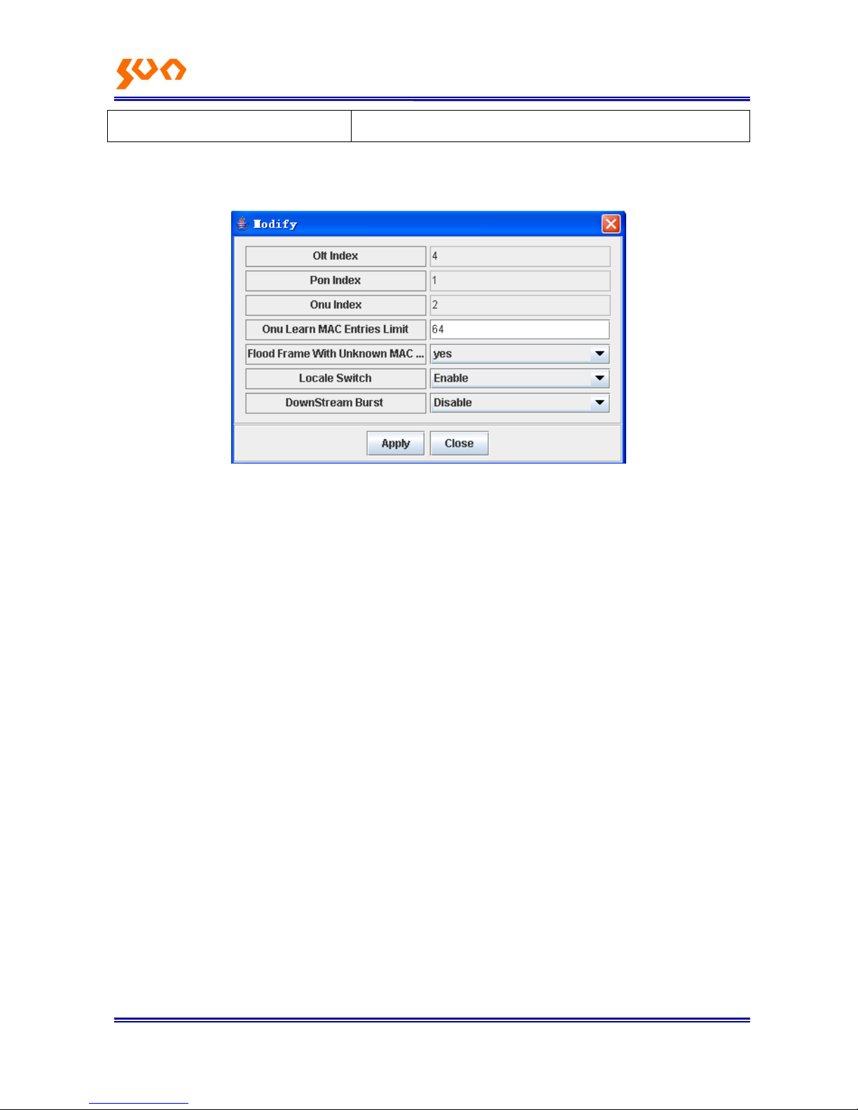
【Bridge Config】 as Figure 4-27.
Figure 4-27
ONU Learn MAC Entries Limit: limit the MAC address number of devices connected to the ONU, if not
limit, config 0.
Flood Frame With Unknown MAC: choose YES, expand the unknown data frame broadcast of
destination MAC to all the ports; choose NO, discard the unknown data frame of destination MAC.
Locale Switch: config local switch function of multi-port ONUs, choose Enable, each port is not isolated;
choose Disable, each port is isolated.
DownStream Burs: open or close downstream Burst function.
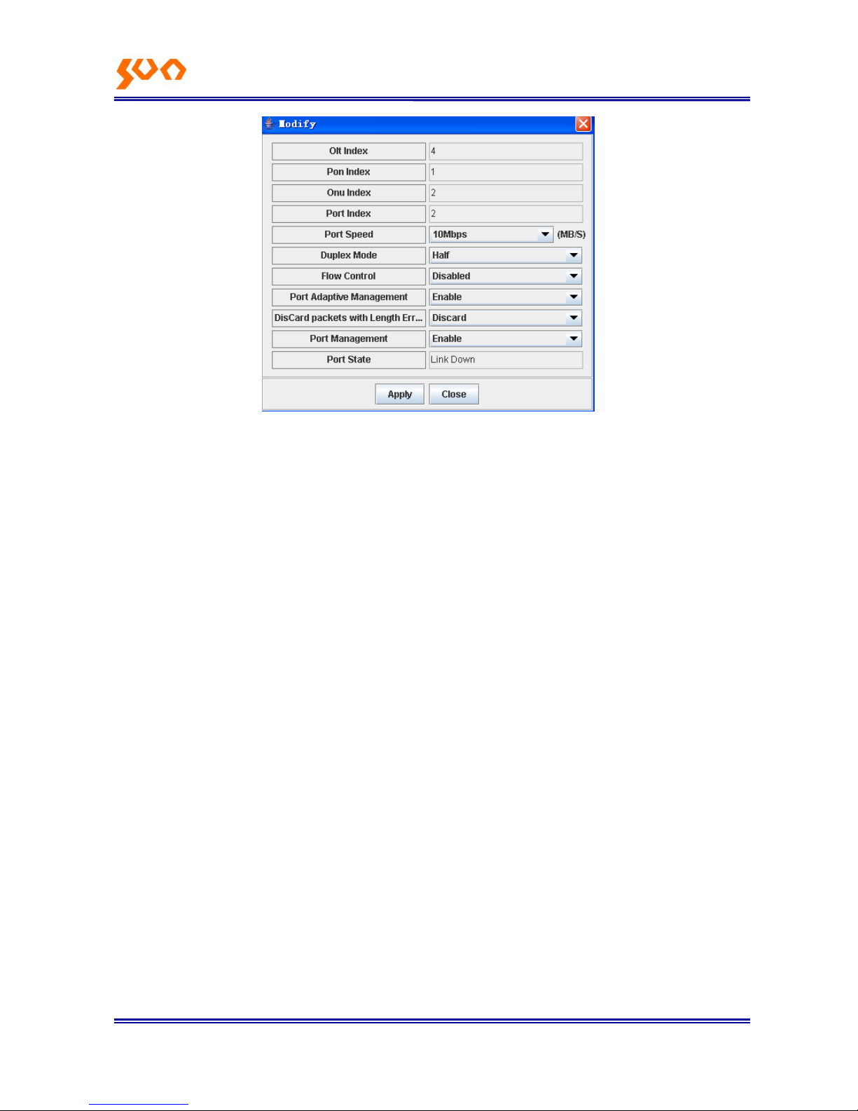
【Port-settings】as Figure 4-28.
Page 37
Fiber Op tic S oluti ons P rovider 23/31
Figure 4-28
Port speed: config port speed
Duplex Mode: set port working mode full duplex or half duplex
Flow Control: enable or close 802.1x flow control
Port Adaptive Management: default is enable
Discard Packets with Length Errors: such as small data packets
Port Management: close or open the port, when close, the port can‘t work
Note: to config Port speed and Duplex Mode, must Disabled Port Adaptive Management.
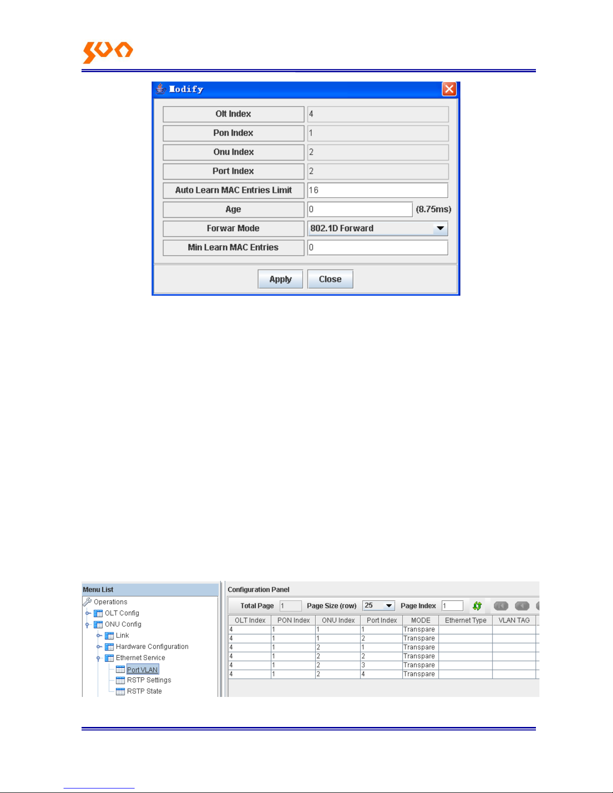
【PortLink-mode Bridge】 as Figure 4-29.
Page 38
Fiber Op tic S oluti ons P rovider 24/31
Figure 4-29
Auto Learn MAC Entries Limit: maximum 64, if not limit, config it to 0.
Age: config the MAC aging time, maximum 32768; minimum 0, means not aging.
Forway Mode: port data packets forward mode, there is 802.1d Forwarding and MAC Access Control
two modes. 802.1d Forwarding actions includes: learn MAC, unicast the known MAC data frame, flood
unknown MAC frame; different with 802.1d Forwarding, under MAC Access Control mode, only after
ONU learned the source MAC of upstream data packet, it will forward this data packet, this character
also called Dropped Unit Learned.
Min Guaranteed MAC Learning Limit: config the minimum entries of MAC learning
4.4.3 ONU Config
【ONU Config】-->【Ethernet Service】 as Figure 4-30, function description as Table 4-6.
Figure 4-30
Page 39

Fiber Op tic S oluti ons P rovider 25/31
Menu
Function Description
【Port VLAN】
Config ONU port VLAN
【RSTP Settings】
RSTP Setting
【RSTP State】
Check RSTP state
Table 4-6
【Port VLAN】
ONU VLAN function support three VLAN modes‖:
Transparent, Tag and Translated mode, details as Table 4-7, 4-8, 4-9.
Direction
Ethernet packet with
or not with VID
Treatment way
Upstream
With VLAN VID
No change to Ethernet packet, reserve the VLAN TAG, forward
No VLAN VID
No change to Ethernet packet, forward
Downstream
With VLAN VID
No change to Ethernet packet, reserve the VLAN TAG, forward
No VLAN VID
No change to Ethernet packet, forward
Table 4-7 Treatment way to the data packet under Transparent mode
Direction
Ethernet packet with
or not with VID
Treatment way
Upstream
With VLAN VID
Discard
No VLAN VID
Add the configed VLAN VID, forward
Downstream
With VLAN VID
Forward to the corresponding port according to the VID
And divest the VID, if the VID is unequal to the configured ID,
discard the packet.
No VLAN VID
Discard
Table 4-8 Treatment way to the data packet under Tag mode
Direction
Ethernet packet with
or not with VID
Treatment way
Upstream
With VLAN VID
If the original VID is the same with forward VID (in tag), divest
this VID, add new tag (Translated Tag) and forward; if different,
Page 40
Fiber Op tic S oluti ons P rovider 26/31
discard
No VLAN VID
Add default VID (VLAN Tag) and forward
Downstream
With VLAN VID
If the original VID is the same with forward VID (in tag), divest
the VID, add new tag (In Tag) and forward; if different, discard
No VLAN tag
Discard
Table 4-9 Treatment way to the data packet under Translated mode
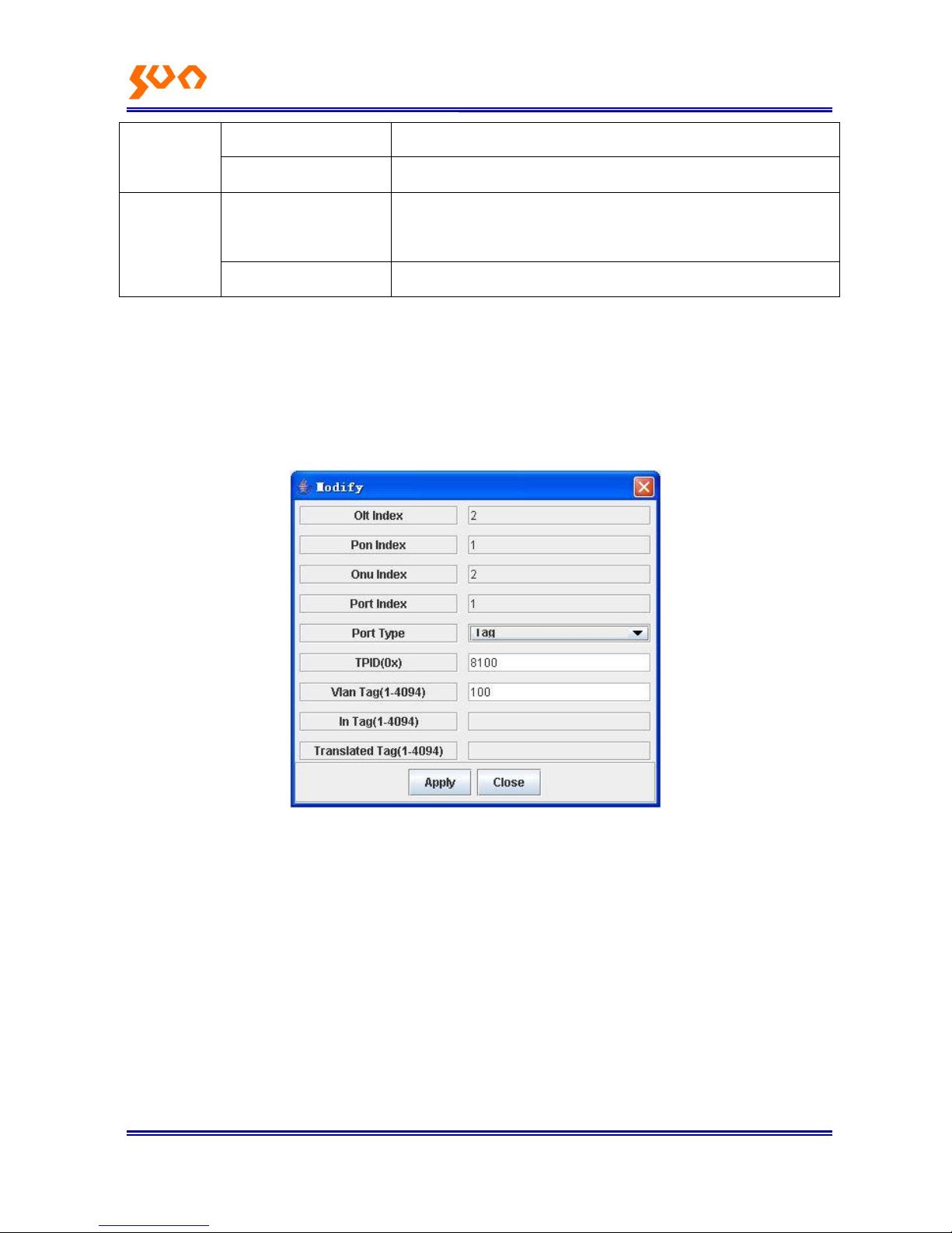
Example: here need to add VLAN VID to the upstream data entering ONU port, and divest the
downstream corresponding VLAN VID, VID is 100.
Choose ONU Port Type as TAG, input 8100 in the TPID column (TPID is Ethernet type, common is
8100), input the VID 100 in the VLAN Tag column, as Figure 4-31.
Figure 4-31
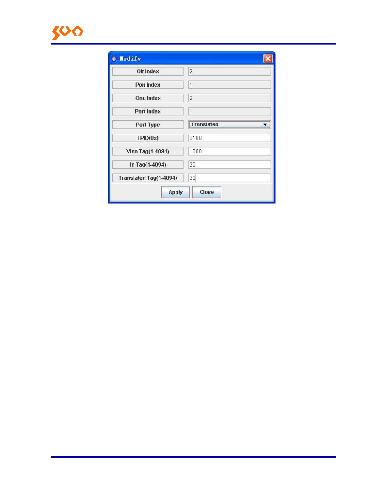
Example: upstream, transfer data packet with VLAN VID 20 to VID 30; downstream, transfer the data
packet with VLAN VID 30 to VID 20.
Choose ONU Port Type as Translated, input Choose ONU Port Type as TAG, input 8100 in the TPID
column (TPID is Ethernet type, common is 8100), transfer the VID 20 to VID 30, input arbitrary value in
the VLAN Tag column, then ONU will add this VID to the packet with VID, as Figure 4-32
Page 41
Fiber Op tic S oluti ons P rovider 27/31
Figure 4--32
Note: if VLAN mode can‘t switch directly between TAG mode and Translated mode, must config VLAN
mode to Transparent mode and then config new mode; under same modes, to change VID, also need
to config VLAN mode to Transparent, then config new mode, reconfigure VID, or the config is not
successful.
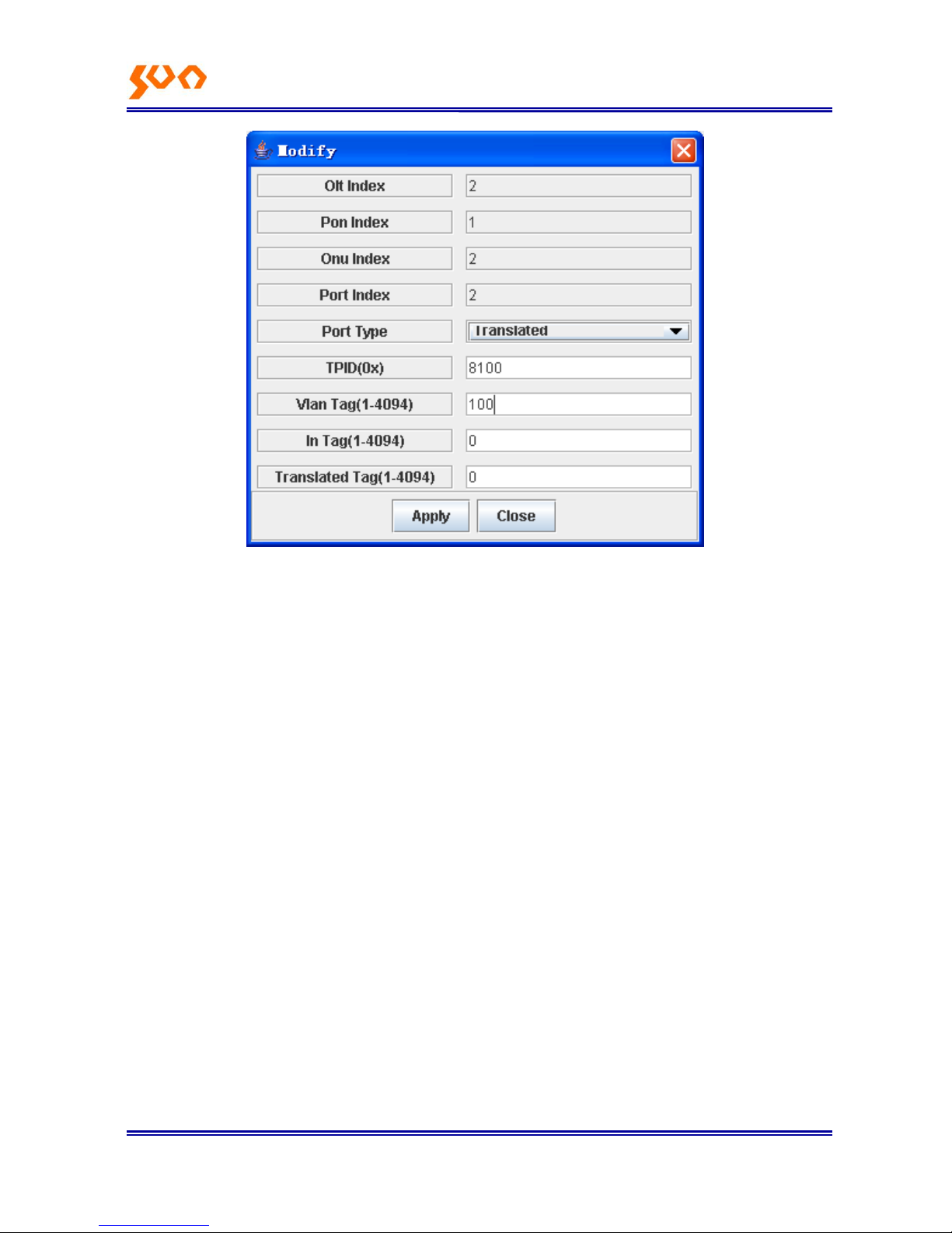
To the ONU SUN-GE8200 and SUN-GE8200D 100M port (port index is 2), TAG mode is not available,
and Translated mode can be used to substitute TAG.
Example:
Here need to add VLAN ID to upstream data, and divest downstream corresponding VLAN VID, VID is
100. Choose Translated mode (it should choose TAG mode, tag mode is not available to index 2 port,
Translated mode can implement the same function) Configure as 4-33.
Page 42
Fiber Op tic S oluti ons P rovider 28/31
Config 4-33
ONU will add VID 100 tag to the data packet without VID, and discard the data packet with VID.
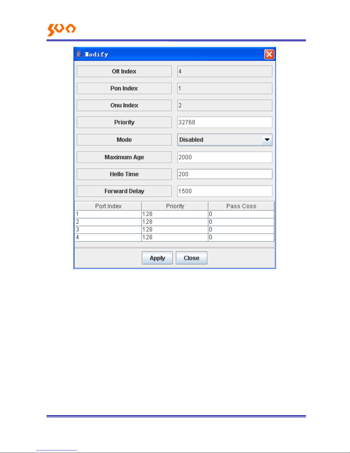
【RSTP Settings】 as Figure 4-44
Page 43
Fiber Op tic S oluti ons P rovider 29/31
Figure 4-44
ONU supports RSTP (Rapid Spanning Tree Protocol) function. It is simple to config RSTP function.
Under default mode, choose Enable in the Mode options under config panel.
Config parameters in the RSTP config panel:
Priority: the size of the priority decides if this network bridge can be taken as root bridge; The small one
can be chosen as root, if all the priority adopts the same value in the whole switch network, the bridge
with smallest MAC can be chosen as root. Under RSTP mode, to config the network bridge priority will
cause the STP recount. Range is 0-65535, default 32768.
Mode: this options supports to enable, close or transparent RSTP function.
Page 44

Fiber Op tic S oluti ons P rovider 30/31
Maximum Age: config the aging time. If this value is too small, the spanning tree counts frequently, this
will covers much resource; if this value is too large, it will not find the link faults timely. According to the
real network condition, we suggest to adopt the default value, range 6—40s, default is 20s.
Hello Time: internal time to send config information. If too small, the network bridge will send the
information frequently, cause high load to the network and CPU; too large, network bridge will take link
packet loss as link fault, cause the spanning tree recount. Suggest to use the default value, rage
1—10s, default is 2s.
Forward Delay: the status forward mechanism spanning tree adopts. RSTP defines three port statuses:
Discarding, Learning and Forwarding. Forward Delay occurs under Discarding and Learning status. If
this value too small, it will lead to temporary redundant path; if too large, network will can‘t connect in
long time. Suggest to use default value, range is 4—30s, default is 15s.
The three time parameters of root bridge Hello Time, Forward Delay and Max Age should apply to the
below formula:
2* (ForwardDelay – 1s) >= MaxAge >= 2* (HelloTime + 1s)
Or the network will vibrate frequently.
Port Priority: port priority is an important matter to choose root port. Under same condition, small value
will be the switch root port. If all the Ethernet port adopts same priority parameter, the range of the
priority depends on the port index. Change priority will lead to the spanning tree recount, range is
0—255, default is 128.
Path Cost: related to link speed, the high the port link speed, the low to configure this parameter, STP
can count the current Ethernet port path overhead.
Page 45
Fiber Op tic S oluti ons P rovider 31/31
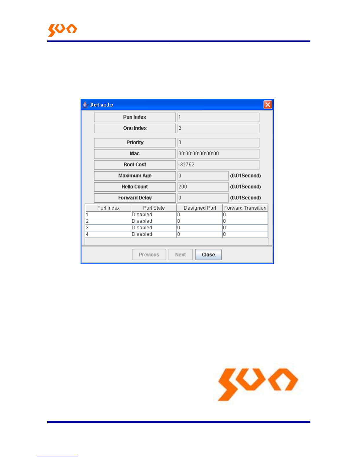
【RSTP State】
Enable RSTP, the whole spanning tree status can check in the【State】table, as Figure 4-45.
Figure 4-45
4.4.4 ONU 802.1x Management
【ONU Config】-->【802.1x】, not available at present.
SHANGHAI SUN TELECOMMUNICATION CO., LTD.
Building No. 145, Lane 666 Xianing Road.
Jinshan Industrial Zone, Shanghai 201506, China
Tel: +86 21 60138638 Fax: +86 21 60138635-401
E-mail: [email protected]
http://www.suntelecom.cn
 Loading...