

Page 1

Sun Fire™ X4450
Volume Configuration Guide
Sun Microsystems, Inc.
www.sun.com
Part No. 820-6889-10
March 2009 Revision A
Submit comments about this document at: http://www.sun.com/hwdocs/feedback
Page 2

Copyright ©2009 SunMicrosystems, Inc., 4150 Network Circle, Santa Clara, California 95054, U.S.A. All rights reserved.
THIS PRODUCT CONTAINS CONFIDENTIAL INFORMATION AND TRADE SECRETS OF SUN MICROSYSTEMS, INC. USE,
DISCLOSURE OR REPRODUCTION IS PROHIBITED WITHOUT THE PRIOR EXPRESSWRITTEN PERMISSION OF SUN MICROSYSTEMS,
INC.
This distributionmay include materials developed by third parties.Sun, Sun Microsystems, the Sunlogo, Java, Netra, Solaris, StarOffice, Sun
Ray, Galaxy Sun Fire Xand the SunSpectrum Pac (Sunburst design) logo are trademarksor registered trademarks of Sun Microsystems, Inc. in
the U.S.and othercountries. Intelis atrademark orregistered trademark of Intel Corporation or its subsidiaries in the United States and other
countries. IntelInside isa trademarkor registered trademarkof IntelCorporation orits subsidiariesin theUnited Statesand othercountries.
This product is covered andcontrolled by U.S. Export Control laws and may be subject to the export or import laws in other countries. Nuclear,
missile, chemicalbiological weaponsor nuclearmaritime enduses orend users,whether direct or indirect, are strictly prohibited. Export or
reexport to countries subject to U.S. embargo or to entities identified on U.S. export exclusion lists, including, but not limited to, the denied
persons andspecially designatednationals listsis strictlyprohibited.
Use ofany spare or replacement CPUsis limitedto repair or one-for-one replacement ofCPUs inproducts exported in compliance with U.S.
export laws. Use of CPUsas product upgrades unless authorized by the U.S. Government is strictly prohibited.
Copyright ©2009 SunMicrosystems, Inc., 4150 Network Circle, Santa Clara, California 95054, Etats-Unis. Tous droits réservés.
CE PRODUIT CONTIENT DES INFORMATIONS CONFIDENTIELLES ET DES SECRETS COMMERCIAUX DE SUN MICROSYSTEMS, INC.
SON UTILISATION, SA DIVULGATION ET SA REPRODUCTION SONT INTERDITES SANS L’AUTORISATION EXPRESSE, ECRITE ET
PREALABLE DE SUN MICROSYSTEMS, INC.
Cette distributionpeut des éléments développés par des tiers. Sun, Sun Microsystems, le logo Sun, Java, Netra, Solaris, StarOffice, Sun Ray,
Galaxy SunFire X et le logo SunSpectrum Pac(Sunburst design)sont desmarques de fabrique ou des marques déposées de Sun Microsystems,
Inc. auxEtats-Unis etdans d’autres pays. Intel est une marquede fabriqueou unemarque déposée de Intel Corporation ou de sa filiale aux
Etats-Unis etdans d’autres pays. Intel Inside est une marque defabrique ouune marque déposée de Intel Corporation ou de sa filiale aux EtatsUnis etdans d’autres pays.
Ce produit est soumis à la législation américaine sur le contrôle des exportations et peut être soumisà larèglementation envigueur dans
d’autres pays dans le domaine des exportations et importations. Les utilisations finales, ou utilisateurs finaux, pour des armes nucléaires, des
missiles, desarmes biologiqueset chimiquesou dunucléaire maritime, directement ou indirectement, sont strictement interdites. Les
exportations oureexportations vers les pays sous embargo américain, ou vers des entités figurant sur les listes d’exclusion d’exportation
américaines, ycompris, maisde maniere non exhaustive, la liste de personnes qui font objet d’un ordre de ne pas participer,d’une façondirecte
ou indirecte, aux exportations des produits oudes servicesqui sontrégis parla législationaméricaine surle contrôledes exportationset laliste
de ressortissants spécifiquement désignés, sont rigoureusement interdites.
L’utilisationde piècesdétachées oud’unités centralesde remplacement estlimitée auxréparations ouà l’échangestandard d’unités centrales
pour lesproduits exportés, conformément à la législation américaine en matière d’exportation. Sauf autorisation par les autorités des EtatsUnis, l’utilisationd’unités centralespour procéder à des mises à jour de produitsest rigoureusement interdite.
Page 3

How to Add Components to Your
Limited Configuration Server
Test the Current Configuration
Always test the current configuration before upgrading the server.
Testing the Current Configuration
1
Ensure that all internal components are properly seated and install the
cover.
2
Boot the server using the server’s Tools and Drivers CD/DVD.
3
The server should pass POST and boot to the Tools and Drivers
CD/DVD’s main menu.
4
Troubleshoot any front panel fault indicators before customizing the
server.
Adding Components to the Server
The component installation procedures in this document contain important
installation and validation information that can assist you in successfully
configuring the server.
1
Page 4

How to Add Memory (DIMMs)
Note – Sun-approved memory is the only memory guaranteed to meet the reliability
and quality levels required for optimal performance of Sun Fire servers. Use only
DIMMs approved and supported by Sun.
Install DIMMs in Matched Part Number Pairs Only.
DIMMs must be installed in matched part number pairs. Matched part number pair
DIMMs have the same size, the same speed, and the same manufacturer.
Installing DIMMs in Matched Part Number Pairs
• Inspect the label on the DIMMs to ensure the following:
• Same manufacturer
• Same part number
Install Larger Capacity DIMMs in Lower-Numbered Slots
Larger capacity DIMMs must be installed in lower-numbered slots. If the DIMMs
that you are installing are larger capacity than the DIMMs already installed in the
server, do the following:
Installing Larger Capacity DIMMs in Lower-Numbered Slots
1
Remove smaller capacity DIMMs from lower-numbered slots and replace
with larger capacity DIMMs.
2
Install smaller capacity DIMMs in the next available higher-numbered
slots.
For example:
If the server is configured with two 2 GB DIMMs in slots A0/B0 and you
want to install two additional 4 GB DIMMs:
• Remove the two 2 GB DIMMs from slots A0/B0
• Install the two 4 GB DIMMs in slots A0/B0
• Install the two 2 GB DIMMs in slots C0/D0
2 Sun Fire X4450 Volume Configuration Guide • March 2009
Page 5
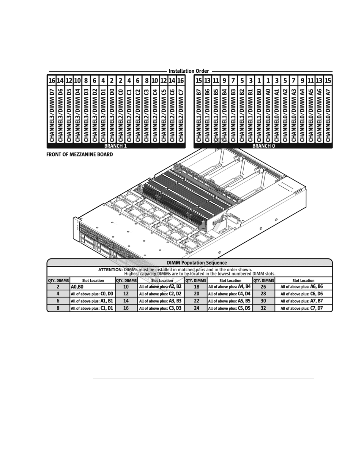
Install DIMMs According to the Following Map
Insure DIMMs are Properly Seated and Locked
DIMMs that are not properly seated and locked are easily dislodged when shipped
or moved.
Seating and Locking DIMMs
• Insert DIMMs into the DIMM slots and lock the DIMMs using the two
locking levers.
How to Add Components to Your Limited Configuration Server 3
Page 6
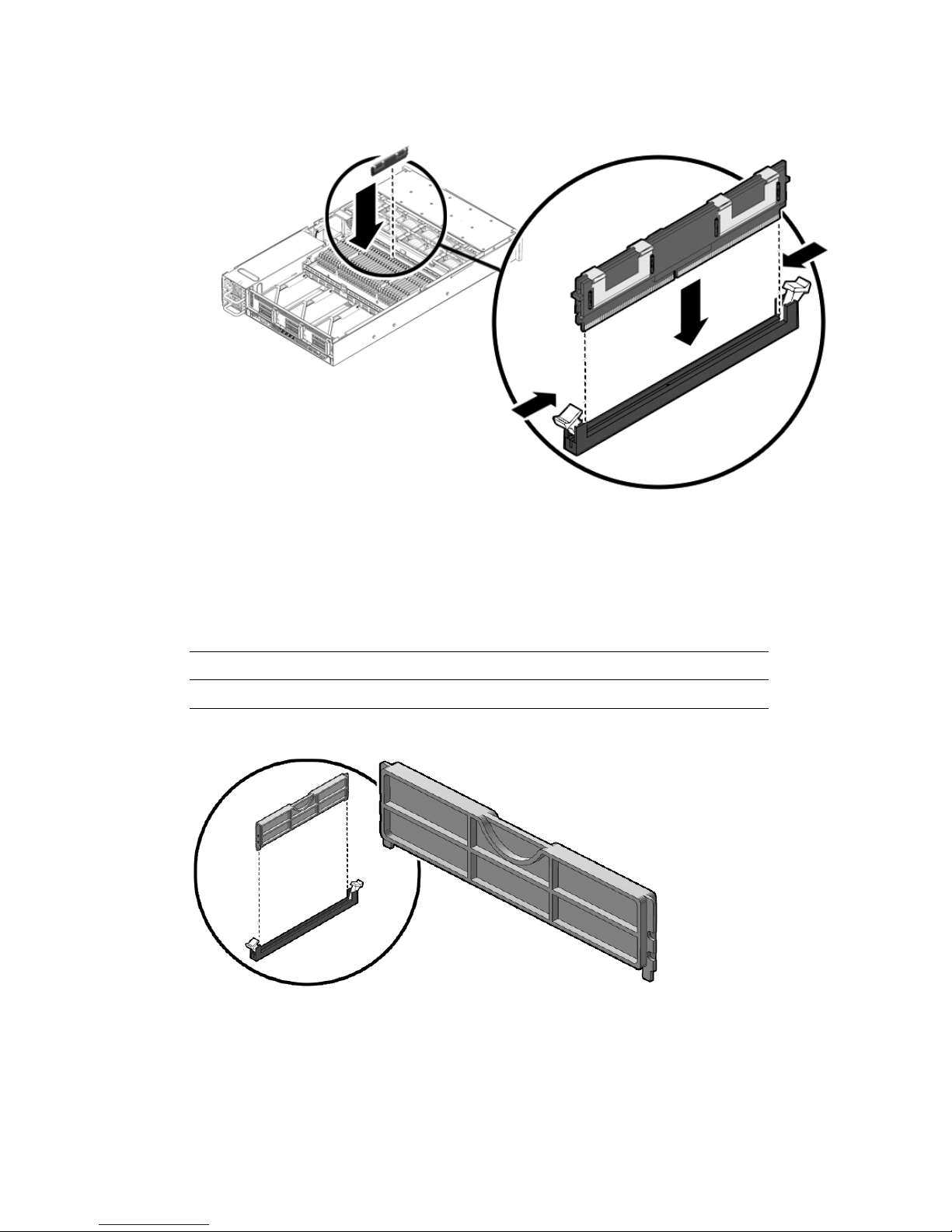
Fill All Unused DIMM Slots With DIMM Slot Fillers
All unused DIMM slots must contain DIMM slot fillers.
Filling DIMM Slots With Slot Fillers
• Insert and lock DIMM fillers into each unused DIMM slot.
4 Sun Fire X4450 Volume Configuration Guide • March 2009
Page 7

Lock the Memory Mezzanine Tray
For server systems that use a memory mezzanine tray (for example, the Sun Fire
X4450), you must lock the mezzanine tray before you install or move the server.
Caution – Unsecured trays or cards are easily dislodged when shipped or moved.
● See the top cover service label for instructions about securing the mezzanine
tray.
Test Installed DIMMs
Verify that the server can see all installed DIMMs.
Testing Installed Memory
• Reassemble the server and use one of the following methods to verify the
DIMMs:
• Boot from the Tools and Drivers CD/DVD and access the diagnostics by
selecting the option to run hardware diagnostics (option 1).
• Log in to the service processor’s (SP) ILOM using ssh or a browser and the IP
address of the SP.
How to Add a DVD/USB Drive
■ The server ships with filler panels for a vacant DVD drive slot and each vacant
HD slot.
■ You must install the DVD drive/USB hub before you install the hard drives.
Adding a DVD/USB Drive Unit
1
Eject all hard drives and HD filler panels.
2
Remove the DVD filler panel.
3
Slide the DVD/USB drive*unit into the DVD slot and engage the connector on
the backplane.
4
Populate the HD slots with hard drives or hard drive filler panels.
5
Test the DVD drive by booting the server using the Tools and Drivers DVD and
accessing the Pc-Check diagnostics.
* Use the -09 (or later) revision of the DVD/USB drive unit.
How to Add Components to Your Limited Configuration Server 5
Page 8

Note – If the DVD drive hangs during testing, contact Sun service. The issue might
be a low-level inter-operability issue between the USB translation device and the
system. The issue is usually resolved by replacing an internal board.
How to Add SAS Hard Drives
See the Sun Intel Adaptec BIOS RAID Utility User’s Manual (820-4708) at:
http://docs.sun.com
SAS HD Installation Rules
■ Do not mix SAS and SATA drives in the same volume.
■ SATA hard drives are not supported on the Sun Fire X4450.
■ Supported HBA cards:
■ Sun StorageTek PCIe SAS 8-Port Internal HBA, SGXPCIE8SAS-I-Z , LSI SAS
1068E (hardware RAID support)
■ Sun StorageTek SAS RAID 8-Port Internal HBA, SG-XPCIESAS-R-INT-Z,
Adaptec/Intel-based (hardware RAID support)
■ If you are also adding a DVD/USB unit, install the unit before installing hard
drives (see “How to Add a DVD/USB Drive” on page 5).
■ Hard drives must be initialized before the drives can be seen by the HBA and
before an OS can access the disks.
Adding SAS Hard Drives
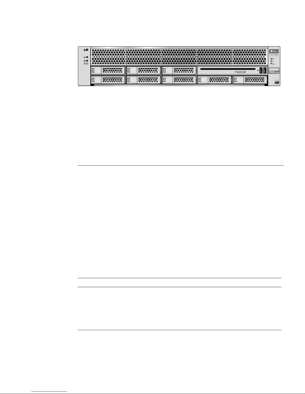
1 Install drives according to the following drive map:
HD1 HD3 HD7 DVD/USB Drive
HD0
HD2 HD4 HD5 HD6
6 Sun Fire X4450 Volume Configuration Guide • March 2009
Page 9
2 Remove protective covers from the connectors on the card and install the HBA
*
(PCIe SAS 8-port internal disk controller)
.
3 Take the free end of the cable that is attached to the disk backplane on the left-
hand side (disks 0-3) and connect it to the Mini-SAS x4 connector on the card
labeled Port 0, 0-3.
4 Take the free end of the cable that is attached to the disk backplane on the right-
hand side (disks 4-7) and connect it to the Mini-SAS x4 connector on the card
labeled Port 1, 4-7.
* Supported HBAs: Sun StorageTek PCIe SAS 8-Port Internal HBA, SGXPCIE8SAS-I-Z, LSI SAS 1068E and Sun
StorageTek SAS RAID 8-Port Internal HBA, SG-XPCIESAS-R-INT-Z, Adaptec/Intel-based
Verify Hard Drives
Use the PCIe HBA’s BIOS utility to verify that the card sees the hard drives.
■ When using the Sun StorageTek (Adaptec) HBA card, you must first initialize the
hard drives using the card’s BIOS (even for single-disk configurations) so the OS
can see the drives (use the Adaptec-based procedure below). The LSI card
automatically manages this step and does not require manual initialization of
drives (use the LSI-based procedure below).
■ After installation, if you see inconsistent or non-illuminated HD LEDs, you might
need to update the backplane and the controller firmware using the server’s Tools
and Drivers DVD.
Verifying Hard Drives Using the LSI-Based Sun StorageTek PCIe SAS 8-port Internal HBA
1 Power on the server and watch the output for the prompt to press Ctrl-C.
2 When the prompt appears, press Ctrl-C.
3 From the main menu, select SAS Topology.
4 Verify that all installed drives are seen by the HBA, and replace any drives that
are not seen.
How to Add Components to Your Limited Configuration Server 7
Page 10

Verifying Hard Drives Using the Adaptec-based Sun StorageTek PCIe SAS 8-port Internal HBA
1
Boot the server and watch the output for the prompt to press Ctrl-A to enter the
Adaptec RAID Configuration Utility (ARCU).
2
When the prompt appears, press Ctrl-A. The Adaptec RAID Configuration Utility
main menu appears.
Initializing the Disks
1
From the Adaptec RAID Configuration Utility main menu, select Create Array.
2
Select Initialize Disks. A list appears showing disks seen by the HBA card.
If an installed disk does not appear in the list, replace it.
3
Use the Insert key to add each disk to the list on the right.
4
When done adding disks to the list, press Enter.
5
To verify the drives, press the ESC key to exit to the main menu.
Verify the Hard Disks
1
Select Disk Utilities.
2
Highlight a drive in the list by using the up or down arrow key, press enter and,
from the menu that appears, select Identify Drive and press Enter. This action
blinks the HD LED.
3
Verify that the selected HD LED blinks.
4
Select Identify Drive for each HD.
5
When done, press ESC to exit to the main menu. The main menu appears.
Creating a Volume for Each Drive
1
From the utility’s main menu, Select Array Configuration Utility.
2
From the main menu, select Create Array to create a volume for each disk.
3
Use the arrow key to highlight drive 0.
4
Use the insert key to add drive 0 to the Selected Drives list on the right and press
enter.
5
Label the volume (you can use the drive volume number) and press Enter
6
Accept the defaults for Read Caching and Write Caching and press Enter.
7
Select Build for the Create RAID Via option and press Enter
8
Press Enter to build the volume.
9
Repeat the steps to create a volume for each drive.
8 Sun Fire X4450 Volume Configuration Guide • March 2009
Page 11

Test Hard Drives
Testing Hard Drives Using Pc-Check
1
2
3
Boot the server with the Tools and Drivers CD/DVD to access the diagnostics.
Select the option to Run Hardware Diagnostics.
Select the option to test hard drives.
Note – To expedite hard drive testing use the 1% test coverage.
How to Add and Test PCIe Cards
■ Slot 0 and slot 1 can accommodate x16 mechanical cards.
■ The disk controller HBA card must be inserted into slot 0 (the slot nearest the
power supply).
■ After installation, update the firmware level for each card as specified by the
manufacturer.
Adding PCIe Cards
1
2
Connect PCIe cards to a riser assembly.
Insert the PCIe card and riser assembly into a PCIe slot on the motherboard.
3
Testing PCIe Cards
1
2
Update the firmware level for each card as specified by the manufacturer.
If the self-test option exists, invoke the cards built in self-test.
Test the card by performing basic rudimentary activities. For example, establish
network connectivity (for a GigabitEthernet card).
How to Check and Update Your Firmware
Sun frequently provides new firmware updates, so it is possible that a newer version
of firmware is available for your server. Sun recommends that you update to the latest
version of firmware. Firmware versions for your server are described in the Sun Fire
X4450 Server Product Notes.
How to Add Components to Your Limited Configuration Server 9
Page 12

Firmware Update Notes
■ The BIOS and SP firmware are matched and, unless specified, should always be
updated in unison.
■ There are two types of SP firmware, ELOM (Embedded Lights Out Manager) and
ILOM (Integrated Lights Out Manager).
■ Before updating your server, you must know the type of firmware (ELOM or
ILOM) installed on the SP.
■ Do not update an ELOM-based SP using ILOM firmware. If you need to convert
an ELOM-based SP to an ILOM-based SP, use the ELOM-to-ILOM migration
process, which is described in the ELOM-to-ILOM Migration Guide .
■ Downgrading firmware is not recommended, because downgrading firmware
might eliminate important security and functionality updates.
■ Recovery procedures for failed updates are described in the product’s Service
Manual.
Checking and Updating Your Firmware
1
Reboot the server and watch the screen for the prompt to press F2 to enter the
BIOS Setup Utility.
2
3
When the prompt appears, press F2. The BIOS Setup Utility main menu appears.
From the main menu, make note of the BIOS Version and the SP Firmware
Version
4
5
Exit the BIOS setup utility.
Access the Sun Fire X4450 server download site at:
http://www.sun.com/servers/x64/x4450/downloads.jsp
6
Compare the most recent BIOS and SP version numbers to the firmware versions
of the server.
7
If necessary, download the firmware and update the server using the ILOM.
10 Sun Fire X4450 Volume Configuration Guide • March 2009
 Loading...