

Page 1

Sun Microsystems, Inc.
www.sun.com
Submit comments about this document by clicking the Feedback[+] link at: http://docs.sun.com
Sun Fire™X4170, X4270, and X4275
Servers Installation Guide
Part No. 820-5827-13
December 2009, Revision A
Page 2

Please
Recycle
Copyright ©2009 Sun Microsystems, Inc., 4150Network Circle, Santa Clara, California 95054, U.S.A. Allrights reserved.
Sun Microsystems, Inc. has intellectual property rightsrelating to technology embodied in the product that is described in this document.In
particular,and without limitation, these intellectual property rights may includeone or more of theU.S. patents listed at
http://www.sun.com/patents andone or more additional patentsor pending patent applicationsin the U.S. andin other countries.
This distributionmay include materials developedby third parties.
Parts ofthe product may be derived from Berkeley BSD systems,licensed from the University of California. UNIX isa registeredtrademark in
the U.S.and in other countries,exclusively licensed through X/Open Company, Ltd.
Sun, SunMicrosystems, the Sun logo, Java, OpenSolaris, Sun Studio,Solaris and Sun Fire are trademarksor registered trademarks of Sun
Microsystems, Inc., orits subsidiaries, in theU.S. and other countries.
Intel isa trademark or registered trademarkof Intel Corporation or its subsidiaries in theUnited States and othercountries. The Adobe logois a
registered trademark of Adobe Systems, Incorporated.
The OPENLOOK and Sun™ GraphicalUser Interface was developedby Sun Microsystems, Inc. forits users and licensees.Sun acknowledges
the pioneeringefforts of Xerox in researching and developingthe concept of visualor graphical user interfacesfor the computer industry. Sun
holds anon-exclusive license from Xerox to theXerox Graphical User Interface, which license also coversSun’s licensees who implement OPEN
LOOK GUIsand otherwise comply withSun’s written license agreements.
Use ofany spare or replacement CPUsis limited to repair orone-for-one replacement of CPUs inproducts exported in compliance withU.S.
export laws.Use of CPUs asproduct upgrades unless authorized by the U.S. Governmentis strictly prohibited.
DOCUMENTATION IS PROVIDED "AS IS" AND ALL EXPRESS OR IMPLIED CONDITIONS, REPRESENTATIONS AND WARRANTIES,
INCLUDING ANY IMPLIED WARRANTY OF MERCHANTABILITY, FITNESS FOR A PARTICULAR PURPOSE OR NON-INFRINGEMENT,
ARE DISCLAIMED, EXCEPT TO THE EXTENT THAT SUCH DISCLAIMERS ARE HELD TO BE LEGALLY INVALID.
Copyright ©2009 Sun Microsystems, Inc., 4150Network Circle, Santa Clara, California 95054, Etats-Unis. Tous droitsréservés.
Sun Microsystems, Inc. détient les droits depropriété intellectuels relatifs à la technologieincorporée dans le produit qui est décrit dansce
document. Enparticulier, et cesans limitation, ces droits depropriété intellectuelle peuvent inclure unou plus des brevets américainslistés à
l’adresse http://www.sun.com/patents etun ou les brevets supplémentaires oules applications de brevet enattente aux Etats -Unis et dans les
autres pays.
Cette distributionpeut comprendre des composants développéspar des tierces parties.
Des partiesde ce produit pourront être dérivées dessystèmes Berkeley BSD licenciéspar l’Université de Californie.UNIX est une marque
déposée auxEtats-Unis et dans d’autres pays et licenciée exclusivementpar X/Open Company, Ltd.
Sun, SunMicrosystems, le logo Sun, Java, OpenSolaris, Sun Studio,Solaris et Sun Fire sontdes marques, ou des marquesdéposée de Sun
Microsystems, Inc., ouses filiales, auxEtats-Unis et autres pays.
Intel estune marque ou une marquedéposée de Intel Corporation,ou ses filiales, auxEtats-Unis, et dans d’autres pays.Le logo Adobe. estune
marque déposée deAdobe Systems, Incorporated.
L’interfaced’utilisation graphique OPEN LOOKet Sun™ a été développée par Sun Microsystems, Inc. pour ses utilisateurset licenciés. Sun
reconnaît les efforts de pionniers de Xerox pourla rechercheet le développement duconcept des interfaces d’utilisationvisuelle ou graphique
pour l’industriede l’informatique. Sun détientune license non exclusivede Xerox sur l’interface d’utilisation graphique Xerox, cette licence
couvrant égalementles licenciés de Sun qui mettent en place l’interfaced’utilisation graphique OPEN LOOK et qui, en outre, se conforment aux
licences écritesde Sun.
L’utilisationde pieces detachees oud’unites centrales de remplacement estlimitee aux reparations ou al’echange standard d’unites centrales
pour lesproduits exportes, conformement a la legislation americaine enmatiere d’exportation. Sauf autorisation par les autorites des EtatsUnis, l’utilisationd’unites centrales pour proceder a des mises ajour de produits est rigoureusement interdite.
LA DOCUMENTATION EST FOURNIE "EN L’ETAT" ET TOUTES AUTRES CONDITIONS, DECLARATIONSET GARANTIES EXPRESSES
OU TACITES SONT FORMELLEMENT EXCLUES, DANS LA MESURE AUTORISEE PAR LA LOI APPLICABLE, YCOMPRIS NOTAMMENT
TOUTE GARANTIE IMPLICITERELATIVE A LA QUALITE MARCHANDE, A L’APTITUDE A UNE UTILISATION PARTICULIERE OU A
L’ABSENCEDE CONTREFACON.
Page 3

iii
Contents
Preface ix
1. Preparing to Install the Sun Fire X4170, X4270, and X4275 Servers 1
Tools and Equipment Needed 1
Server Installation Task Checklist 2
Opening the Box 3
Unpacking 3
Package Contents Inventory 4
Options 4
ESD Precautions 4
Server Description 5
Front Panel Features 5
Back Panel 8
Server Supported Components 10
Sun Fire X4170 Server Supported Components and Capabilities 10
Sun Fire X4270 and X4275 Servers Supported Components 12
Server Specifications 13
Physical Specifications 13
Electrical Specifications 14
Environmental Requirements 15
Page 4

iv Sun Fire X4170, X4270, and X4275 Servers Installation Guide • December 2009
2. Installing Server Options 17
Planning the Installation of Options 18
Before You Begin 18
Avoid Electrostatic Discharge 18
Run Server Diagnostics 19
About Server Component Filler Panels 19
Filler Panel Purpose 19
Filler Panel Removal and Installation 19
Performing Electrostatic Discharge and Antistatic Prevention Measures 21
Electrostatic Discharge Safety Measures 21
Using an Antistatic Wrist Strap 22
Using an Antistatic Mat 22
ESD Handling Procedure 22
Preparing the Server to Install Options 22
▼ Prepare Server to Install Options 23
Removing the Server Top Cover 23
▼ Remove the Top Cover From the Sun Fire X4170 and X4270 Servers 24
▼ Remove the Top Cover From the Sun Fire X4275 Server 25
Installing Memory Modules (DIMMs) 26
DIMM and CPU Physical Layout 26
DIMM Population Rules 28
DIMM Rank Classification Labels 29
▼ Install DIMMs 29
Installing a CPU 32
▼ Install the CPU 32
Installing Hard Disk Drives 34
Server Hard Drive Locations 34
Server Hard Disk Drive Configuration Rules 36
Page 5

Contents v
Installing a Hard Disk Drive 37
▼ Install the Hard Disk Drive 37
Installing a PCIe Card 38
PCIe Card Configuration Rules 38
▼ Install a PCIe Card 39
Installing a Power Supply 46
▼ Install a Power Supply 46
Installing the Server Top Cover 48
▼ Install the Server Top Cover 48
3. Installing the Server Into a Rack With Slide-Rails 51
Before You Begin 51
Server Installation Process Overview 52
Rail Assemblies 52
Service Label 52
Checking Rack Compatibility 53
Disassembling Slide-Rails 54
▼ Disassemble Bolt-On Slide-Rails 55
▼ Disassemble Tool-less Slide-Rails 56
Installing the Mounting Brackets Onto the Server 56
▼ Install Mounting Brackets 56
Attaching the Slide-Rail Assemblies to the Rack 58
▼ Attach Bolt-On Slide-Rail Assemblies 58
▼ Attach Tool-less Slide-Rail Assemblies 61
Installing the Server Into the Slide-Rail Assemblies 61
▼ Install Server Into the Slide-Rail Assemblies 62
Installing the Cable Management Arm 65
▼ Install Cable Management Arm 65
Verifying Operation of the Slide-Rails and CMA 72
Page 6

vi Sun Fire X4170, X4270, and X4275 Servers Installation Guide • December 2009
▼ Verify Operation of Slide-Rails and CMA 72
4. Setting Up the Server 73
Connecting the Cables 74
Connector Locations 74
▼ Cable the Server 75
Connecting to the ILOM Service Processor for the First Time 78
About ILOM SP IP Addresses 78
About ILOM SP Interfaces 78
Determining the ILOM SP IP Address 79
▼ Use the BIOS Setup Utility to View the Assigned ILOM SP IP
Address 79
▼ Use a Serial Connection to View the Assigned ILOM SP IP Address
80
Changing the ILOM SP IP Address 81
▼ Use the BIOS Setup Utility to Change the ILOM SP IP Address 82
▼ Use the Serial Connection to Change the ILOM SP IP Address 82
Example 1 82
Example 2 83
▼ Use a Web Browser to Change the ILOM SP IP Address 83
Applying Main Power to the Server for the First Time 84
▼ Apply Main Power to the Server 84
5. Configuring the Preinstalled
Solaris 10 Operating System 87
Before You Begin 88
Installation Worksheet 88
Configuring the Preinstalled Solaris 10 Operating System 92
▼ Configure the Preinstalled Solaris 10 OS 92
▼ Redirect the Console Output to the Video Port (Optional) 94
Page 7

Contents vii
Configuring Server RAID Drives 95
RAID Drive Overview 95
RAID Drive Options 96
Mirroring the Preinstalled Solaris OS With LSI RAID 97
▼ Create a Mirror Image of the Preinstalled Solaris OS 97
Mirroring the Preinstalled Solaris OS With Sun StorageTek HBA Card 98
▼ Create a Mirror Image of the Preinstalled Solaris OS 98
Solaris 10 Operating System User Information 100
Solaris 10 User Documentation 100
Solaris 10 OS Training 100
Using the Solaris Installation Program 100
Sun Java Enterprise System 101
Sun Studio 11 101
Reinstalling the Solaris Operating System 101
Download Solaris Operating System 101
6. Configuring the Preinstalled
OpenSolaris Operating System 103
Before You Begin 104
Installation Worksheet 104
Configuring the Preinstalled OpenSolaris Operating System 108
▼ Accessing the System Over the Network 108
▼ Accessing the System Locally 109
▼ Configure the Preinstalled OpenSolaris Operating System 110
▼ (Optional) Redirect the Console Output to the Video Port 111
▼ (Optional) Modify the GRUB Menu to Auto Boot 112
Getting Started on OpenSolaris 113
Configuring Server RAID Drives 114
RAID Drive Overview 114
Page 8

viii Sun Fire X4170, X4270, and X4275 Servers Installation Guide • December 2009
RAID Drive Options 115
Mirroring the Preinstalled OpenSolaris OS With LSI RAID 116
▼ Create a Mirror Image of the Preinstalled OpenSolaris OS With LSI
RAID 116
Mirroring the Preinstalled OpenSolaris OS With Sun StorageTek HBA Card 117
▼ Create a Mirror Image of the Preinstalled OpenSolaris OS With Sun
StorageTek 117
OpenSolaris Operating System User Information 119
Using the OpenSolaris Installation Program 119
Reinstalling the OpenSolaris Operating System 119
Download OpenSolaris Operating System 120
7. If You Need Help 121
Powering On and Off the Server 121
▼ Power On the Main Power 121
▼ Power Off from Main Power Mode 122
Setup Troubleshooting 122
Contacting Support 124
Index 127
Page 9

ix
Preface
The Sun Fire X4170, X4270, and X4275 Servers Installation Guide contains hardware
installation procedures and configuration procedures for the preinstalled Solaris and
OpenSolaris Operating Systems. You perform these procedures to bring the server to
a configurable and usable state.
This document is intended for system administrators, network administrators, and
service technicians who have an understanding of server systems.
Product Updates
For product updates that you can download for the Sun Fire X4170, X4270, and
X4275 Servers, visit the following web site:
http://www.sun.com/download/index.jsp
Find the Hardware Drivers section and click x64 Servers & Workstations. The Sun
Fire X4170, X4270, and X4275 Servers sites contain updates for firmware and drivers,
as well as CD-ROM .iso images.
Related Documentation
The related documents listed in the following table are available online at:
http://docs.sun.com/app/docs/prod/sf.x4170#hic
http://docs.sun.com/app/docs/prod/sf.x4270#hic
http://docs.sun.com/app/docs/prod/sf.x4275#hic
Page 10

x Sun Fire X4170, X4270, and X4275 Servers Installation Guide • December 2009
Title Content Part Number Format
Sun Fire X4170, X4270, and
X4275 Servers Product Notes
Late-breaking information
about the server
820-5831 PDF
HTML
Sun Fire X4170, X4270, and
X4275 Servers Getting Started
Guide
Basic installation information
for setting up the server
820-5833 PDF
Print
Sun Fire X4170, X4270, and
X4275 Servers Installation
Guide
Detailed installation
information for setting up the
server
820-5827 PDF
HTML
Print option
Sun Fire X4170, X4270, and
X4275 Servers Linux, VMware,
Solaris and OpenSolaris
Operating Systems Installation
Guide
Installation instructions for
the Linux, VMware, Solaris,
and OpenSolaris operating
systems
820-5828 PDF
HTML
Sun Fire X4170, X4270, and
X4275 Servers Windows
Operating System Installation
Guide
Installation instructions for
the Windows Server
operating system
820-5829 PDF
HTML
Sun Installation Assistant for
Linux and Windows User’s
Guide
Instructions for using the Sun
Installation Assistant to
install the Windows and
Linux operating systems
820-3357 PDF
HTML
Sun Fire X4170, X4270, and
X4275 Servers Service Manual
Information and procedures
for maintaining and
upgrading the server
820-5830 PDF
HTML
Sun x64 Servers Diagnostics
Guide
Information for diagnosing
and troubleshooting the
server
820-6750 PDF
HTML
x64 Servers Utilities Reference
Manual
Information for using
applications and utilities
common to x64 servers
820-1120 PDF
HTML
Sun Integrated Lights Out
Manager 3.0 Documentation
Collection
These documents cover ILOM
features and tasks that are
common to servers and
server modules that support
ILOM 3.0
820-5523
820-6410
820-6411
820-6412
820-6413
PDF
HTML
Sun Integrated Lights Out
Manager 2.0 User’s Guide
ILOM features and tasks that
are common to servers and
server modules that support
ILOM 2.0
820-1188 PDF
HTML
Page 11

Preface xi
Translated versions of some of these documents are available at the web site
described above in French, Simplified Chinese, and Japanese. English documentation
is revised more frequently and might be more up-to-date than the translated
documentation.
Documentation, Support, and Training
Sun Integrated Lights Out
Manager (ILOM) 3.0
Supplement for Sun Fire X4170,
X4270, and X4275 Servers
ILOM 3.0 information that is
specific to the Sun Fire X4170,
X4270, and X4275 Servers
820-7959 PDF
HTML
Sun Integrated Lights Out
Manager (ILOM) 2.0
Supplement for Sun Fire X4170,
X4270, and X4275 Servers
ILOM 2.0 information that is
specific to the Sun Fire X4170,
X4270, and X4275 Servers
820-7629 PDF
HTML
Sun Fire X4170, X4270, and
X4275 Servers Safety and
Compliance Guide
Hardware safety and
compliance information for
the server
820-5832 PDF
Important Safety Information
for Sun Hardware Systems
Multilingual hardware safety
and compliance information
for all Sun hardware system
816-7190 Print
Sun Function URL
Sun Documentation http://docs.sun.com
Support http://www.sun.com/support/
Training http://www.sun.com/training/
Title Content Part Number Format
Page 12

xii Sun Fire X4170, X4270, and X4275 Servers Installation Guide • December 2009
Using UNIX Commands
This document might not contain information about basic UNIX®commands and
procedures such as shutting down the system, booting the system, and configuring
devices. Refer to the following for this information:
■ Software documentation that you received with your system
■ Solaris™ Operating System documentation, which is at:
http://docs.sun.com
■ OpenSolaris™ Operating System documentation, which is at:
http://opensolaris.org/os/documentation/
Third-Party Web Sites
Sun is not responsible for the availability of third-party web sites mentioned in this
document. Sun does not endorse and is not responsible or liable for any content,
advertising, products, or other materials that are available on or through such sites or
resources. Sun will not be responsible or liable for any actual or alleged damage or
loss caused by or in connection with the use of or reliance on any such content,
goods, or services that are available on or through such sites or resources.
Page 13

Preface xiii
Typographic Conventions
Sun Welcomes Your Comments
Sun is interested in improving its documentation and welcomes your comments and
suggestions. You can submit your comments by going to:
http://www.sun.com/hwdocs/feedback
Please include the title and part number of your document with your feedback:
Sun Fire X4170, X4270, and X4275 Servers Installation Guide, part number 820-5827-13.
Typeface
*
* The settings on your browser might differ from these settings.
Meaning Examples
AaBbCc123 The names of commands, files,
and directories; on-screen
computer output
Edit your.login file.
Use ls -a to list all files.
% You have mail.
AaBbCc123 What you type, when contrasted
with on-screen computer output
%
su
Password:
AaBbCc123 Book titles, new words or terms,
words to be emphasized.
Replace command-line variables
with real names or values.
Read Chapter 6 in the User’s Guide.
These are called class options.
You must be superuser to do this.
To delete a file, enter rm filename.
Page 14

xiv Sun Fire X4170, X4270, and X4275 Servers Installation Guide • December 2009
Page 15

1
CHAPTER
1
Preparing to Install the Sun Fire
X4170, X4270, and X4275 Servers
This chapter describes the Sun Fire X4170, X4270, and X4275 Servers hardware and
the information you need to know before you begin to install the servers into a rack.
It includes the following topics:
■ “Tools and Equipment Needed” on page 1
■ “Server Installation Task Checklist” on page 2
■ “Opening the Box” on page 3
■ “Server Description” on page 5
■ “Server Supported Components” on page 10
■ “Server Specifications” on page 13
Tools and Equipment Needed
To install the system, you need the following tools:
■ No. 2 Phillips screwdriver
■ ESD mat and grounding strap
■ Pencil, stylus, or other pointed device, for pushing front panel buttons
You also need a system console device, such as one of the following:
■ Sun workstation
■ ASCII terminal
■ Terminal server
■ Patch panel connected to a terminal server
Page 16

2 Sun Fire X4170, X4270, and X4275 Servers Installation Guide • December 2009
Server Installation Task Checklist
TABLE 1-1 summarizes an ordered list of tasks that you must perform to properly
install the server.
TABLE 1-1 Installation Task Checklist
Step Task Description For Instructions, See:
1 Unpack the server and any optional
components ordered for the server
from the shipping containers
• “Opening the Box” on page 3
2 If applicable, install the optional server
module components prior to installing
the server module into the chassis
• Chapter 2 “Installing Server
Options” on page 17
3 Install the server into a rack • Chapter 3 “Installing the Server Into
a Rack With Slide-Rails” on page 51
4 Connect cables to the server, configure
the ILOM service processor, and apply
main power to the server
• Chapter 4 “Setting Up the Server”
on page 73
5 If ordered, configure the factory-
installed Solaris or OpenSolaris
Operating System image shipped on
one of the storage drives
• Chapter 5 “Configuring the
Preinstalled Solaris 10 Operating
System” on page 87
• Chapter 6 “Configuring the
Preinstalled OpenSolaris Operating
System” on page 103
If applicable, install one of the
following operating systems:
• Red Hat Enterprise Linux
• SUSE Linux Enterprise Server 10
• Solaris 10 Operating System
• OpenSolaris Operating System
• VMware
• Sun Fire X4170, X4270, and X4275
Servers Linux, VMware, Solaris, and
OpenSolaris Operating Systems
Installation Guide (820-5828)
• Microsoft Windows Server 2003 or
2008 Operating System
• Sun Fire X4170, X4270, and X4275
Servers Windows Operating System
Installation Guide (820-5829)
Page 17
Chapter 1 Preparing to Install the Sun Fire X4170, X4270, and X4275 Servers 3
Opening the Box
Carefully open the shipping box.
Unpacking
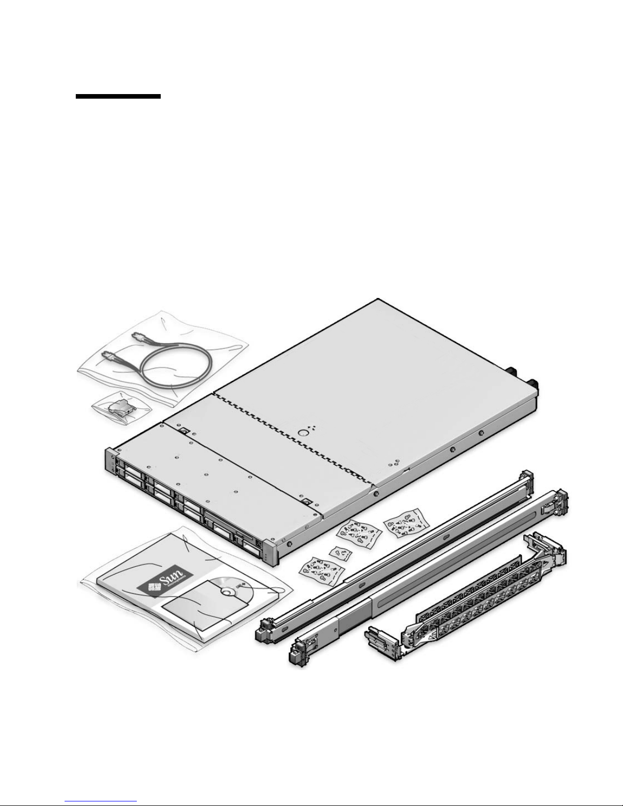
Unpack all server components from the packing cartons. FIGURE 1-1 shows the
packing contents:
FIGURE 1-1 Unpacking the Box
Page 18

4 Sun Fire X4170, X4270, and X4275 Servers Installation Guide • December 2009
Package Contents Inventory
The following items should be packaged with the Sun Fire X4170, X4270, and X4275
Servers:
■ Sun Fire X4170, X4270, or X4275 Server
■ Power cord, packaged separately with country kit
■ (Optional) Sun Fire X4170, X4270, and X4275 Server Documentation and Media
Kit, including the following:
■ Sun Fire X4170, X4270, and X4275 Servers Installation Guide (this document)
■ License and safety documentation
■ Tools & Drivers DVD (includes drivers and additional software), Sun
Installation Assistant (SIA) CD/DVD, and SunVTS CD/DVD
■ (Optional) Rackmount kit containing rack rails and installation instructions
Options
Standard server components are installed at the factory. However, ordered options
such as additional memory or PCI Express cards are shipped separately. If possible,
install optional components before installing the server in a rack. For instructions for
installing server options, see “Installing Server Options” on page 17.
ESD Precautions
Electronic equipment is susceptible to damage by static electricity. Use a grounded
antistatic wriststrap, footstrap, or equivalent safety equipment to prevent
electrostatic discharge (ESD) when you install or service the server.
Caution – To protect electronic components from electrostatic discharge, which can
permanently disable the system or require repair by Sun service technicians, place
components on an antistatic surface, such as an antistatic discharge mat, an antistatic bag,
or a disposable antistatic mat. Wear an antistatic grounding strap connected to a metal
surface on the chassis when you work on system components.
Page 19
Chapter 1 Preparing to Install the Sun Fire X4170, X4270, and X4275 Servers 5
Server Description
This section shows the front and back of the Sun Fire X4170, X4270, and X4275
Servers.
Front Panel Features
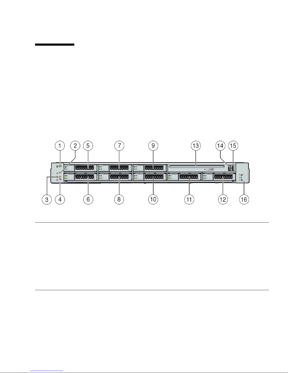
FIGURE 1-2 shows the Sun Fire X4170 Server front panel and describes its components.
FIGURE 1-2 Sun Fire X4170 Server Front Panel
Figure Legend
1 Locator LED/Locator button: white 9 Hard disk drive 5 (optional)
2 Service Action Required LED: amber 10 Hard disk drive 4 (optional)
3 Power/OK LED: green 11 Hard disk drive 6 (optional)
4 Power button 12 Hard disk drive 7 (optional)
5 Hard disk drive 1 (optional) 13 DVD drive (optional)
6 Hard disk drive 0 (optional) 14 USB 2.0 connector (2)
7 Hard disk drive 3 (optional) 15 USB 2.0 connector (3)
8 Hard disk drive 2 (optional) 16 Power Supply Service Action Required LED: amber
System Overtemperature LED: amber
Fan Module Service Action Required LED: amber
Page 20
6 Sun Fire X4170, X4270, and X4275 Servers Installation Guide • December 2009
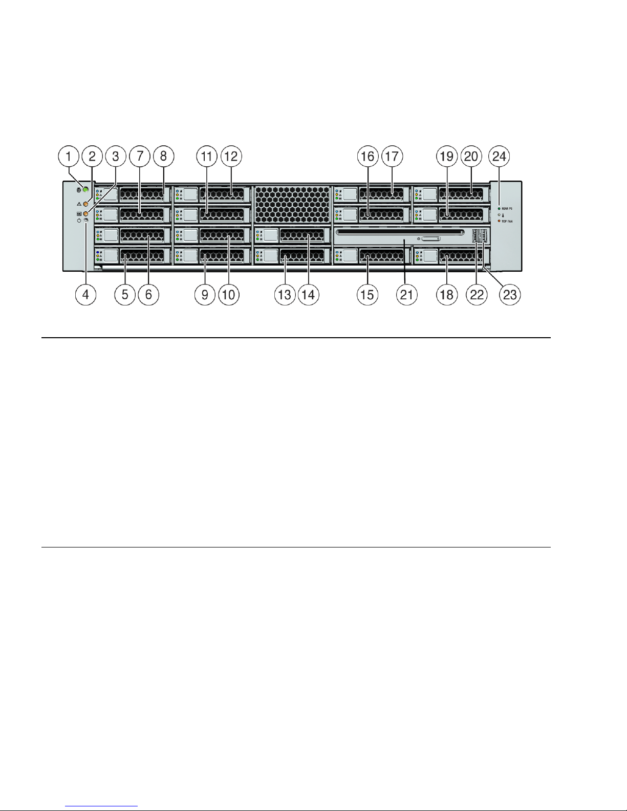
FIGURE 1-3 shows the Sun Fire X4270 front panel and describes its components.
FIGURE 1-3 Sun Fire X4270 Server Front Panel
Figure Legend
1 Locator LED/Locator button: white 13 Hard disk drive 8 (optional)
2 Service Action Required LED: amber 14 Hard disk drive 9 (optional)
3 Power/OK LED: green 15 Hard disk drive 10 (optional)
4 Power button 16 Hard disk drive 11 (optional)
5 Hard disk drive 0 (optional) 17 Hard disk drive 12 (optional)
6 Hard disk drive 1 (optional) 18 Hard disk drive 13 (optional)
7 Hard disk drive 2 (optional) 19 Hard disk drive 14 (optional)
8 Hard disk drive 3 (optional) 20 Hard disk drive 15 (optional)
9 Hard disk drive 4 (optional) 21 DVD drive (optional)
10 Hard disk drive 5 (optional) 22 USB 2.0 connector (2)
11 Hard disk drive 6 (optional) 23 USB 2.0 connector (3)
12 Hard disk drive 7 (optional) 24 Power Supply Service Action Required LED: amber
System Overtemperature LED: amber
Fan Module Service Action Required LED: amber
Page 21
Chapter 1 Preparing to Install the Sun Fire X4170, X4270, and X4275 Servers 7
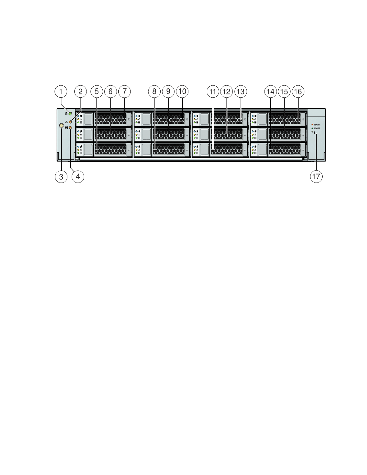
FIGURE 1-4 shows the Sun Fire X4275 Server front panel and describes its components.
FIGURE 1-4 Sun Fire X4275 Server Front Panel
Figure Legend
1 Locator LED/Locator button: white 9 Hard disk drive 4 (optional)
2 Service Action Required LED: amber 10 Hard disk drive 5 (optional)
3 Power button 11 Hard disk drive 6 (optional)
4 Power/OK LED: green 12 Hard disk drive 7 (optional)
5 Hard disk drive 0 (optional) 13 Hard disk drive 8 (optional)
6 Hard disk drive 1 (optional) 14 Hard disk drive 9 (optional)
7 Hard disk drive 2 (optional) 15 Hard disk drive 10 (optional)
8 Hard disk drive 3 (optional) 16 Hard disk drive 11 (optional)
17 Fan Module Service Action Required LED: amber
Power Supply Service Action Required LED: amber
System Overtemperature LED: amber
Page 22
8 Sun Fire X4170, X4270, and X4275 Servers Installation Guide • December 2009
Back Panel
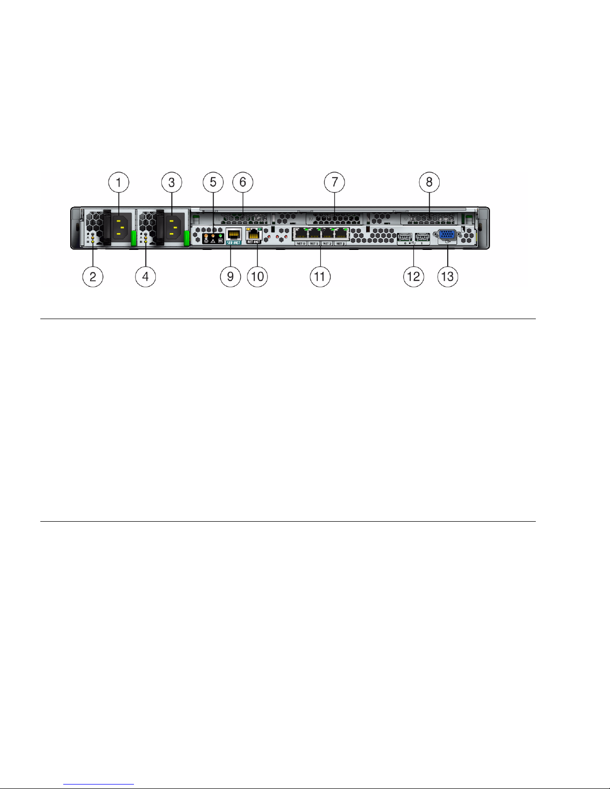
FIGURE 1-5 shows the Sun Fire X4170 Server back panel and describes its components.
FIGURE 1-5 Sun Fire X4170 Server Back Panel
Figure Legend
1 Power supply unit 0 connector 7 PCI Express Module slot (1)
2 Power supply unit 0 status indicator LEDs:
Power Supply OK: green
Power Supply Fail: amber
AC OK: green
8 PCI Express Module slot (2)
3 Power supply unit 1 connector 9 Serial management (SER MGT)/RJ-45 serial port
4 Power supply unit 1 status indicator LEDs:
Power Supply OK: green
Power Supply Fail: amber
AC OK: green
10 Service processor (SP) network management (NET
MGT port)
5 System status LEDs:
Power: green
Attention: amber
Locate: white
11 Gigabit Ethernet ports NET 0, 1, 2, 3
6 PCI Express Module slot (0) 12 USB 2.0 ports (0, 1)
13 HD15 video connector (analog VGA)
Page 23
Chapter 1 Preparing to Install the Sun Fire X4170, X4270, and X4275 Servers 9
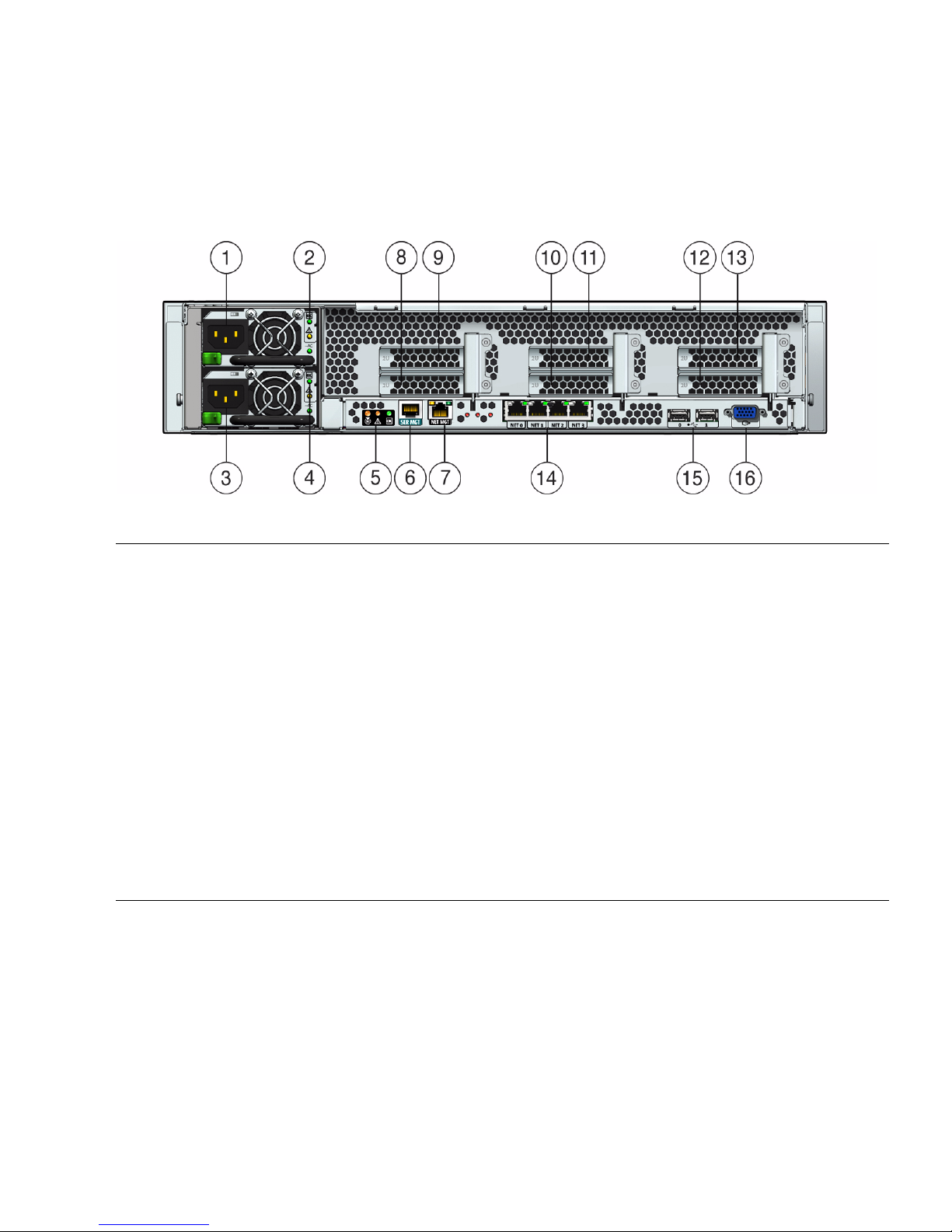
FIGURE 1-6 shows the Sun Fire X4270 and X4275 Servers back panels and describes
their components.
FIGURE 1-6 Sun Fire X4270 and X4275 Servers Back Panel
Figure Legend
1 Power supply unit 1 connector 9 PCI Express Module slot (3)
2 Power supply unit 1 status indicator LEDs:
Power Supply OK: green
Power Supply Fail: amber
AC OK: green
10 PCI Express Module slot (1)
3 Power supply unit 0 connector 11 PCI Express Module slot (4)
4 Power supply unit 0 status indicator LEDs:
Power Supply OK: green
Power Supply Fail: amber
AC OK: green
12 PCI Express Module slot (2)
5 System status LEDs:
Power: green
Attention: amber
Locate: white
13 PCI Express Module slot (5)
6 Serial management (SER MGT)/RJ-45 serial port 14 Gigabit Ethernet ports NET 0, 1, 2, 3
7 Service processor (SP) network management (NET
MGT) port
15 USB 2.0 ports (0, 1)
8 PCI Express Module slot (0) 16 HD15 video connector (analog VGA)
Page 24

10 Sun Fire X4170, X4270, and X4275 Servers Installation Guide • December 2009
Server Supported Components
Sun Fire X4170 Server Supported Components
and Capabilities
Caution – Configuration restriction: SATA disk drives are not supported on Sun
Fire X4170 systems with CPUs that have a power consumption rating higher than 80
watts. Systems with 95-watt CPUs support SAS drives only.
The following table describes the components and capabilities of the Sun Fire X4170
Server.
TABLE 1-1 Sun Fire X4170 Server Components
Component X4170 Server
CPU One or two quad-core processors with three integrated DDR3 memory controllers
per processor. The following CPU sizes are supported:
• 2.26 GHz/80 Watts
• 2.40 GHz/60 Watts
• 2.53 GHz/80 Watts
• 2.93 GHz/95 Watts
Memory Nine DIMMs per processor for a maximum of 18 DIMMs and a maximum of 144
GB of memory
Storage devices • Up to six 2.5-inch SATA hard drive devices (HDDs) or four solid-state drives
(SSDs)
• Up to eight 2.5-inch SAS/SATA HDDs or four SSDs with the optional Hardware
RAID controller
• DVD-RW drive
• Compact Flash slot (internally accessible)
USB ports Two front, two rear, and one internal
PCI Express 2.0 I/O slots Three low-profile PCIe Gen2 slots (one x16, two x8) or three low-profile, 5.0 GT/s
PCIe Gen2 slots (one x16, two x8)
PCI Express I/O cards For a list of I/O cards that are customer-orderable options, go to the following
web site and click on the options card link:
• http://www.sun.com/servers/x64/x4170/
• http://www.sun.com/servers/x64/x4270/
• http://www.sun.com/servers/x64/x4275/
Page 25

Chapter 1 Preparing to Install the Sun Fire X4170, X4270, and X4275 Servers 11
Ethernet ports Four Gigabit Ethernet (GbE) ports on rear panel
Each Network Interface Card (NIC) supports I/O Acceleration Technology 3
(IOAT3)
Service processor Uses the SP subsystem
Includes the Baseboard Management Controller (BMC), which supports the
industry-standard IPMI feature set
Supports remote KVMS over IP
Includes serial port
Supports Ethernet access to SP through a dedicated 10/100BaseT management
port and optionally through one of the host GbE ports (sideband management)
Power supplies Up to two hot-pluggable power supplies
Cooling fans Redundant hot-pluggable fans
Management software Sun Integrated Lights Out Manager
TABLE 1-1 Sun Fire X4170 Server Components (Continued)
Component X4170 Server
Page 26

12 Sun Fire X4170, X4270, and X4275 Servers Installation Guide • December 2009
Sun Fire X4270 and X4275 Servers Supported
Components
The following table describes the components and capabilities of the Sun Fire X4270
and X4275 Servers.
TABLE 1-2 Sun Fire X4270 and X4275 Servers Components and Capabilities
Component X4270 and X4275 Servers
CPU One or two quad-core processors with three integrated DDR3 memory controllers per
processor. The following CPU sizes are supported:
• 2.26 GHz/80 Watts
• 2.40 GHz/60 Watts
• 2.53 GHz/80 Watts
• 2.93 GHz/95 Watts
Memory Nine DDR3 DIMMs per processor for a maximum of 18 DDR3 DIMMs and a maximum
of 144 GB of memory
Storage devices Storage drives supported by the Sun Fire X4270 and X4275 Servers with the LSI 3081E
SAS RAID controller (required):
• Up to sixteen 2.5-inch SAS/SATA HDDs (only supported on X4270 Server)
• Up to twelve 3.5-inch SAS/SATA HDDs (only supported on X4275 Server)
• DVD-RW drive (only supported on X4270 Server)
• CompactFlash slot (internally accessible)
Storage drives supported by the Sun Fire X4270 and X4275 Servers with Sun
StorageTek SAS RAID controller (required):
• Up to eight 2.5-inch SAS/SATA SDDs (only supported on X4270 Server)
• Up to sixteen 2.5-inch SAS/SATA HDDs (only supported on X4270 Server)
• Up to eight 3.5-inch SAS/SATA SSDs (only supported on X4275 Server)
• Up to twelve 3.5-inch SAS/SATA HDDs (only supported on X4275 Server)
• DVD-RW drive (only supported on X4270 Server)
• CompactFlash slot (internally accessible)
USB ports X4270 Server: Two front, two rear, and one internal
X4275 Server: Two rear and one internal
PCI Express 2.0 I/O
slots
Six x8 low-profile PCIe Gen2 slots or six low-profile PCIe Gen2 (5.0 GT/s) slots
PCI Express I/O
cards
For a list of I/O cards that are customer-orderable options, go to the following web site
and click on the options card link:
• http://www.sun.com/servers/x64/x4170/
• http://www.sun.com/servers/x64/x4270/
• http://www.sun.com/servers/x64/x4275/
Page 27

Chapter 1 Preparing to Install the Sun Fire X4170, X4270, and X4275 Servers 13
Server Specifications
Physical Specifications
TABLE 1-3 lists the physical specifications of the Sun Fire X4170, X4270, and X4275
Servers.
Ethernet ports Four Gigabit Ethernet (GbE) ports on rear panel
Each Network Interface Card (NIC) supports I/O Acceleration Technology 3 (IOAT3)
Service processor Uses the SP subsystem
Includes the Baseboard Management Controller (BMC), which supports the industrystandard IPMI feature set
Supports remote KVMS over IP
Includes a serial port
Supports Ethernet access to SP through a dedicated 10/100BaseT management port and
optionally through one of the host GbE ports (sideband management)
Power supplies Up to two hot-pluggable power supplies
Cooling fans Redundant hot-pluggable fans
Management
software
Supports Sun Integrated Lights Out Manager 2.0 and 3.0
TABLE 1-3 Servers Physical Specifications
Parameter Sun Fire X4170 Server Sun Fire X4270 Server Sun Fire X4275 Server
Height 1.71 inches/43.43 mm 3.34 inches/84.84 mm 3.45 inches/87.6 mm
Width 16.75 inches/425.45 mm 16.75 inches/425.45 mm 17.2 inches/436.8 mm
Depth 28.0 inches/711.25 mm 28.0 inches/711.25 mm 30.13 inches/765.25 mm
Weight 36 lbs/16.36 kg 49 lbs/22.27 kg 65 lbs/29.54 kg
TABLE 1-2 Sun Fire X4270 and X4275 Servers Components and Capabilities (Continued)
Component X4270 and X4275 Servers
Page 28

14 Sun Fire X4170, X4270, and X4275 Servers Installation Guide • December 2009
Electrical Specifications
TABLE 1-4 lists the electrical specifications for the Sun Fire X4170, X4270, and X4275
Servers.
Note – The power dissipation numbers listed in the following table are the
maximum rated power numbers for the power supply used in these servers. The
numbers are not a rating of the actual power consumption of the system. For up to
date information on the power consumption, see the power calculators for the Sun
Fire X4170, X4270, and X4275 Servers on the web at:
http://www.sun.com/powercalculators
TABLE 1-4 Servers Electrical Specifications
Parameter Value
Sun Fire X4170 Server
Input
Nominal frequencies 50/60 Hz
Nominal voltage range 100-120/200-240 VAC
Maximum current AC RMS 8.8A @ 100 VAC
AC operating range 90-264 VAC
Output
3.3 VDC STBY 3.6A
+12 VDC 62.3 A
Power dissipation
Max power consumption 873 W
Max heat output 2977 BTU/hr
Volt-Ampere rating 891 VA @ 240 VAC, 0.98 P.F.
Sun Fire X4270 and X4275
Servers
Input
Nominal frequencies 50/60 Hz
Nominal voltage range 100-120/200-240 VAC
Maximum current AC RMS 13.8A @ 100 VAC
AC operating range 90-264 VAC
Output
Page 29

Chapter 1 Preparing to Install the Sun Fire X4170, X4270, and X4275 Servers 15
Environmental Requirements
TABLE 1-5 lists the environmental requirements for the Sun Fire X4170, X4270, and
X4275 Servers.
3.3 VDC STBY 3.0 A
+12 VDC 86.7 A
Power dissipation
Max power consumption 1235.3 W
Max heat output 4212 BTU/hr
Volt-Ampere rating 1261 VA @ 240 VAC, 0.98 P.F.
TABLE 1-5 Servers Environmental Requirements
Parameter Value
Operating temperature
(single, non-rack system)
5oCto35oC (41oFto95oF)
Nonoperating temperature
(single, non-rack system)
-40
o
Cto70oC (-40oF to 158oF)
Operating humidity(single,
non-rack system)
10% to 90% relative humidity, non-condensing
Nonoperating humidity
(single, non-rack system)
Up to 93% relative humidity, non-condensing
Altitude (operating) (single,
non-rack system)
• For the X4170 and X4270 Servers: Up to 3000 m, maximum
ambient temperature is derated by 1 degree C per 300 m
above 900 m
• For the X4275 Server: Up to 3048 m, maximum ambient
temperature is derated by 1 degree C per 300 m above 900 m
Altitude (nonoperating)
(single, non-rack system)
Up to 12,000 m
TABLE 1-4 Servers Electrical Specifications (Continued)
Parameter Value
Page 30

16 Sun Fire X4170, X4270, and X4275 Servers Installation Guide • December 2009
Page 31

17
CHAPTER
2
Installing Server Options
This chapter describes how to install optional components into the Sun Fire X4170,
X4270, and X4275 Servers. Topics discussed in this chapter include:
■ “Planning the Installation of Options” on page 18
■ “Performing Electrostatic Discharge and Antistatic Prevention Measures” on
page 21
■ “Preparing the Server to Install Options” on page 22
■ “Removing the Server Top Cover” on page 23
■ “Installing Memory Modules (DIMMs)” on page 26
■ “Installing a CPU” on page 32
■ “Installing Hard Disk Drives” on page 34
■ “Installing a PCIe Card” on page 38
■ “Installing a Power Supply” on page 46
■ “Installing the Server Top Cover” on page 48
Page 32

18 Sun Fire X4170, X4270, and X4275 Servers Installation Guide • December 2009
Planning the Installation of Options
Before installing the server options into the server chassis, you should review these
topics:
■ “Before You Begin” on page 18
■ “Avoid Electrostatic Discharge” on page 18
■ “Run Server Diagnostics” on page 19
■ “About Server Component Filler Panels” on page 19
Before You Begin
Before you begin the installation of the options, you should have:
■ Reviewed Chapter 1 of this document.
■ Located the shipping packaging that contains the options that you are about to
install into the server.
Avoid Electrostatic Discharge
Internal modules and options are electronic components that are extremely sensitive
to static electricity. Ordinary amounts of static from your clothes or work
environment can destroy components.
To prevent static damage whenever you are accessing any of the internal server
components, you must:
■ Use an antistatic wrist strap. Attach this wrist strap to your wrist and ground the
other end of strap to the system chassis (sheet metal). For additional information,
see the instructions that are shipped with the strap.
■ Place static sensitive components such as memory modules, hard drives, CPUs,
PCIe cards and other server components on an antistatic surface. The following
items can be used as an antistatic surface:
■ The bag used to ship the component.
■ Sun Electronic Discharge (ESD) mat, Sun part number 250-1088 (available
through your Sun Sales representative).
Page 33

Chapter 2 Installing Server Options 19
Run Server Diagnostics
Before you install server options, you should always run diagnostics on the server to
ensure that the server is operating properly. After you install the server options, you
should run the diagnostics again. This approach will ensure that the server is
working properly before you place the server in service.
For instructions for running diagnostics on a server that is being installed for the
first time or a server that is already in service, see the Sun x64 Servers Diagnostics
Guide.
About Server Component Filler Panels
Each server is shipped with module-replacement filler panels for CPUs, hard disk
drives (HDDs), memory modules (DIMMs), PCIe cards, and power supplies. These
filler panels are installed at the factory and must remain in the server until you
replace them with a purchased module.
As needed, consult the following sections when installing server option:
■ “Filler Panel Purpose” on page 19
■ “Filler Panel Removal and Installation” on page 19
Filler Panel Purpose
A filler panel is an empty metal or plastic enclosure that does not contain any
functioning system hardware or cable connectors. These panels must remain in any
unused module slots (CPU, HDDs, DIMMs, PCIe cards, power supplies) to ensure
proper air flow throughout the system. If you remove a filler panel and continue to
operate your system with an empty module slot, the operating performance of your
system could decline.
Filler Panel Removal and Installation
Before you can install a server option into the server, you must remove the filler
panel from the location into which you intend to install the option. When you
remove an option from the server, you must install either a replacement option or a
filler panel.
Page 34

20 Sun Fire X4170, X4270, and X4275 Servers Installation Guide • December 2009
TABLE 2-1 describes how to remove and install server filler panels.
TABLE 2-1 Server Filler Panel Removal and Replacement Procedures
Filler Panel Type Removal Procedure Install Procedure
Memory 1. Locate the memory module filler panel
to be removed from the motherboard.
2. Simultaneously press down on both
ejector levers at the ends of the memory
module slot.
3. Lift the filler panel straight up to remove
it from the memory module socket.
1. Locate the vacant memory module slot on the
motherboard.
2. Ensure that ejector levers at both ends of the
memory module slot are in a fully opened
position.
3. Align the memory module filler panel with
with the empty slot, then gently press the
filler panel into the slot until both ejector
levers close, locking the filler panel in place.
CPU
Note - CPUs
should only be
removed or
installed by Sun
qualified service
personnel.
1. To remove the CPU filler panel in the
socket, pull the release lever away from
the socket into a fully opened position.
2. Lift the bail and then gently lift the filler
panel straight up and out of the CPU
socket.
1. Ensure that the CPU socket release lever and
bail are in a fully opened position.
2. Gently insert the filler panel onto the exposed
pins in the CPU socket.
3. After the filler panel is fully seated in the
socket, close the bail onto the top of the filler
panel, then pivot the release lever down and
into the locked position at the side of the
socket.
Disk Drive 1. Locate the disk drive filler panel to be
removed from the server.
2. To unlatch the disk drive filler panel,
press the release lever button then tilt
the lever up into a fully opened position.
3. To remove the filler panel from the slot,
hold the opened release lever and gently
slide the filler panel toward you.
1. Locate the vacant disk drive module slot in
the server, then ensure that the release lever
on the filler panel is fully opened.
2. Slide the filler panel into the vacant slot by
pressing the middle of the filler panel
faceplate with your thumb or finger.
The release lever will lower as it makes
contact with the chassis. Do not slide the
filler panel in all the way. Leave the filler
panel out approximately 0.25 to 0.50 inch (6
to 12 mm) from the opening
3. Using your thumb or finger, press on the
middle of the filler panel faceplate until the
release lever engages with the chassis.
4. Close the release lever until it clicks into
place and is flush with the front of the server.
Page 35
Chapter 2 Installing Server Options 21
Performing Electrostatic Discharge and
Antistatic Prevention Measures
Electrostatic Discharge Safety Measures
Electrostatic discharge (ESD) sensitive devices, such as the PCIe cards, hard drives,
CPUs, and memory cards, require special handling.
Caution – Circuit boards and hard drives contain electronic components that are
extremely sensitive to static electricity. Ordinary amounts of static electricity from
clothing or the work environment can destroy the components located on these
boards. Do not touch the components along their connector edges.
Caution – You must disconnect both power supplies before servicing some of the
components documented in this chapter.
PCI Slot For Sun Fire X4170 Servers:
1. Remove the server top cover.
2. Remove the PCI slot filler panel from the
location into which you intend to install
the PCIe card.
For Sun Fire X4270 and X4275 Servers:
1. Remote the server top cover.
2. Remove the server crossbar.
3. Remove the PCI slot filler panel from the
location into which you intend to install
the PCIe card.
For Sun Fire X4170 Servers:
1. Remove the server top cover.
2. Press the PCI filler panel into the vacant PCI
slot.
For Sun Fire X4270 and X4275 Servers:
1. Remove the server top cover.
2. Remove the server crossbar.
3. Press the PCI filler panel into the vacant PCI
slot.
4. Replace the server crossbar.
Power supply 1. To release the filler panel side latches,
use your fingers to press and hold both
sides of the filler panel away from the
sides of the power supply bay.
2. Using fingers on your other hand, grasp
the lip at the bottom of the filler panel
and pull it out of the power supply bay.
1. Position the filler panel in the power supply
bay so that the closed end is facing inward
and the lip that is used to remove the filler
panel is in the bottom position.
2. Press the filler panel into the power supply
bay until it is flush with the power supply
bay.
TABLE 2-1 Server Filler Panel Removal and Replacement Procedures (Continued)
Filler Panel Type Removal Procedure Install Procedure
Page 36

22 Sun Fire X4170, X4270, and X4275 Servers Installation Guide • December 2009
Using an Antistatic Wrist Strap
Wear an antistatic wrist strap and use an antistatic mat when handling components
such as hard drive assemblies, circuit boards, or PCIe cards. When servicing or
removing server components, attach an antistatic strap to your wrist and then to a
metal area on the chassis. Following this practice equalizes the electrical potentials
between you and the server.
Note – An antistatic wrist strap is not shipped with the servers. However, antistatic
wrist straps are included with options.
Using an Antistatic Mat
Place ESD-sensitive components on an antistatic mat.
ESD Handling Procedure
1. Prepare an antistatic surface to set parts on during the removal, installation, or
replacement process.
Place ESD-sensitive components such as the printed circuit boards on an
antistatic mat. The following items can be used as an antistatic mat:
■ Antistatic bag used to wrap a Sun replacement part
■ Sun ESD mat, part number 250-1088
■ A disposable ESD mat (shipped with some optional system components)
2. Attach an antistatic wrist strap.
When servicing or removing server components, attach an antistatic strap to your
wrist and then to a metal area on the chassis.
Preparing the Server to Install Options
Before you can install any server options, you must prepare the server.
Page 37

Chapter 2 Installing Server Options 23
▼ Prepare Server to Install Options
To prepare the server to install the options, complete the following tasks:
1. Do one of the following:
■ If the server is being placed into service for the first time, unpack the server
from the shipping container.
See “Opening the Box” on page 3.
■ If the server is already in service, remove it from service and power it down.
2. Ensure that the server AC power cord (or cords) is disconnected from the server.
3. Remove the server top cover.
Before you remove the server top cover, you must ensure that no power is being
applied to the server.
See “Removing the Server Top Cover” on page 23.
Note – If you are installing an HDD or a power supply, it is not necessary to remove
the server top cover.
Removing the Server Top Cover
The procedure for removing the server top cover varies depending on the server
type.
■ For the Sun Fire X4170 and X4270 Servers, see “Remove the Top Cover From
the Sun Fire X4170 and X4270 Servers” on page 24.
■ For the Sun Fire X4275 Server, see “Remove the Top Cover From the Sun Fire
X4275 Server” on page 25.
Caution – Removing the top cover without properly powering down the server and
disconnecting the AC power cords from the power supplies will result in a chassis
intrusion switch failure. This failure causes the server to be immediately powered off
and the SP to operate in degraded mode. When the top cover is reinstalled, the SP
will continue to operate in a degraded mode and the DIMM inventory reported to
the ILOM CLI and web interface will be incorrect. To return the server to normal
operating mode, reinstall the top cover, and disconnect and reconnect the AC power
cords or reboot the SP.
Page 38
24 Sun Fire X4170, X4270, and X4275 Servers Installation Guide • December 2009
▼ Remove the Top Cover From the Sun Fire X4170
and X4270 Servers
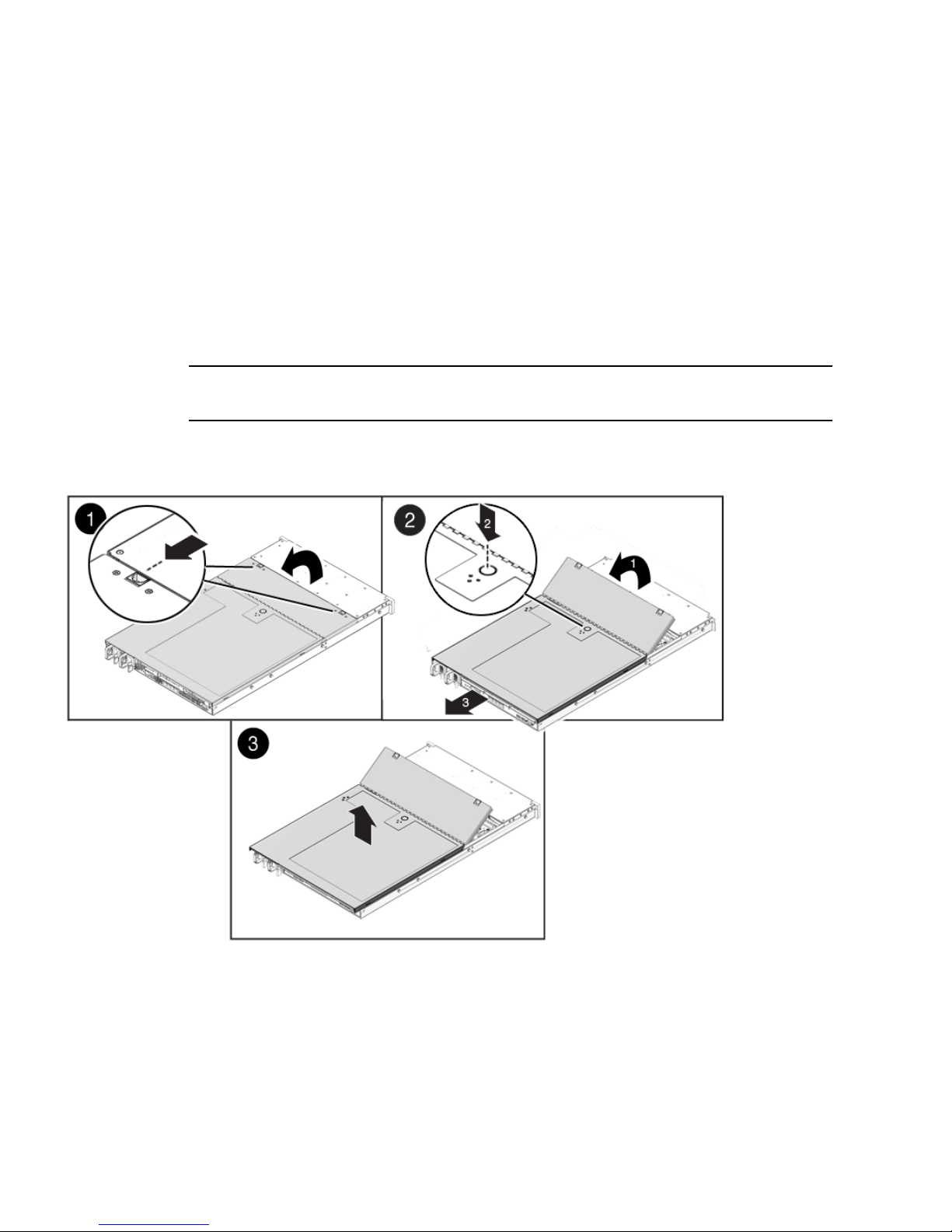
1. Ensure that the AC power cords are disconnected from the server power
supplies.
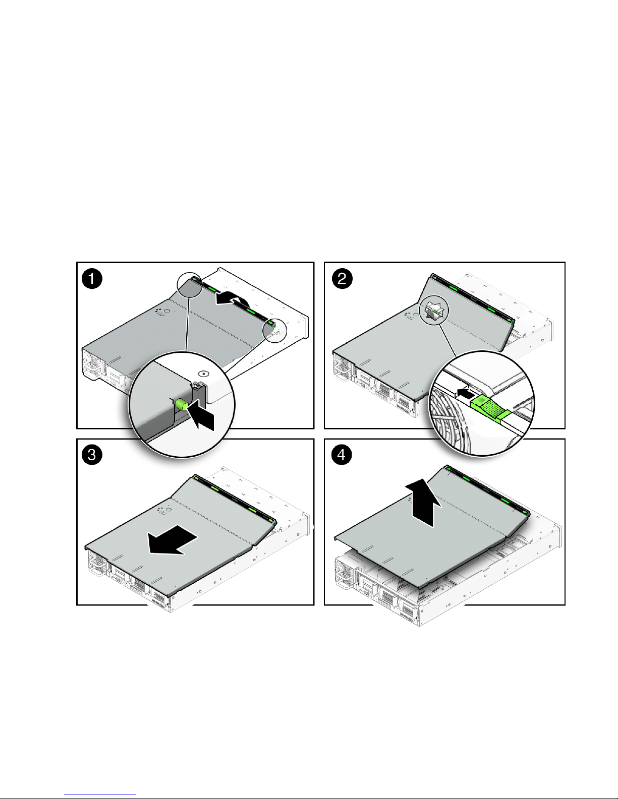
2. Unlatch the fan module door (
FIGURE 2-1 [1]).
Pull the two release tabs back to release the door. Rotate the fan door to the open
position and hold it there.
Note – FIGURE 2-1 shows the Sun Fire X4170 Server, not the Sun Fire X4270 Server;
however, the procedure for removing the top cover is the same for both servers.
FIGURE 2-1 Removing the Sun Fire X4170 or X4270 Server Top Cover
3. Press the top cover release button and slide the top cover toward the rear of the
server about 0.5 inch (12 mm) [2].
4. Lift up and remove the top cover [3].
Page 39
Chapter 2 Installing Server Options 25
▼ Remove the Top Cover From the Sun Fire X4275
Server
1. Ensure that the AC power cords are disconnected from the server power
supplies.
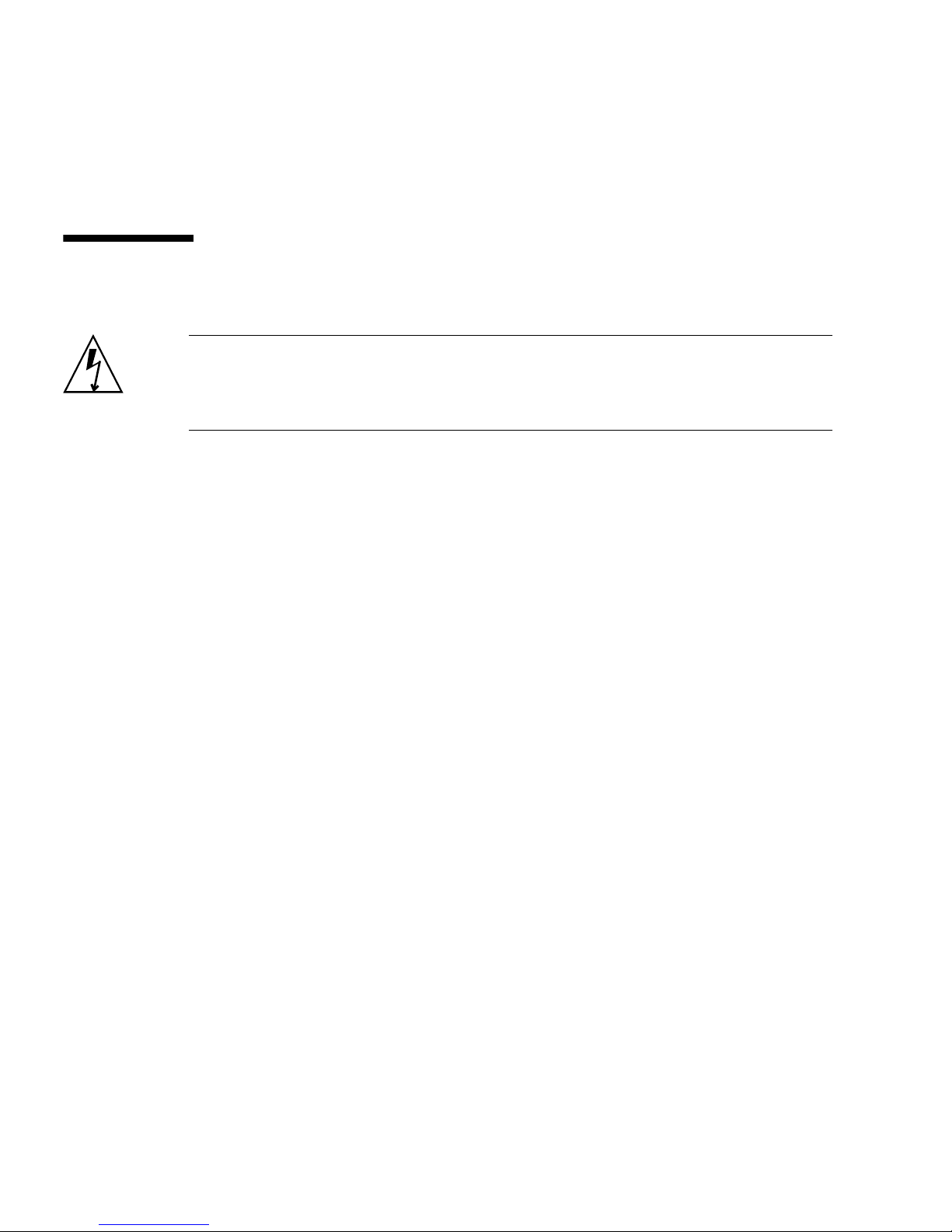
2. Unlatch the fan module door (
FIGURE 2-1 [1]).
Press the two green release buttons on the sides of the fan module door to release
the door. Rotate the fan module door to the open position and hold it there.
FIGURE 2-2 Removing the Sun Fire X4275 Server Top Cover
3. Release the top cover.
Locate the green tab to the right (facing the front of the server) and to the rear of
the fan modules and slide the tab to the right-most position [2].
Page 40
26 Sun Fire X4170, X4270, and X4275 Servers Installation Guide • December 2009
4. Slide the top cover toward the rear of the server about a 0.5 inch (12 mm) [3].
5. Lift up and remove the top cover [4].
Installing Memory Modules (DIMMs)
Caution – This procedure requires that you handle components that are sensitive to
static discharge. This sensitivity can cause the component to fail. To avoid damage,
ensure that you follow antistatic practices as described in “Performing Electrostatic
Discharge and Antistatic Prevention Measures” on page 21.
The servers support a variety of DIMM configurations that can include quad-rank
(QR) DIMMs, dual-rank (DR) DIMMs, or single-rank (SR) DIMMs. When replacing
or upgrading a DIMM on the server you should consider the following:
■ Physical layout of the DIMMs and CPUs
For details, see “DIMM and CPU Physical Layout” on page 26.
■ DIMM population rules
For details, see “DIMM Population Rules” on page 28.
■ Instructions for installing a DIMM
For details, see “Install DIMMs” on page 29.
■ DIMM rank classifications labels
For details, see “DIMM Rank Classification Labels” on page 29.
DIMM and CPU Physical Layout
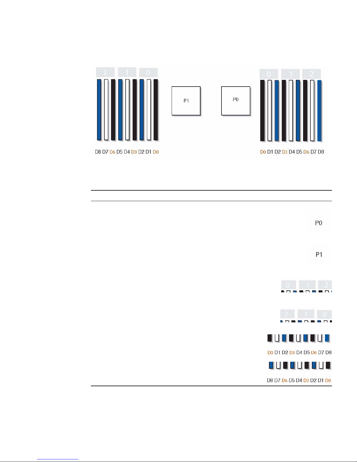
The physical layout of the DIMMs and CPUs is shown in FIGURE 2-3 and TABLE 2-2.
Page 41
Chapter 2 Installing Server Options 27
FIGURE 2-3 CPU and DIMM Physical Layout
TABLE 2-2 CPUs and DIMMs Physical Layout
CPUs and DIMMs Physical Layout
CPU 0 location
CPU 1 location
Channel locations for CPU 0
Three channels per CPU with each channel containing three
color-coded DIMM slots (black, white, and blue).
Channel locations for CPU 1
Three channels per CPU with each channel containing three
color-coded DIMM slots (blue, white and black).
DIMM slot numbering per CPU; with D8 as the farthest slot
away from CPU.
P0:
P1:
Page 42

28 Sun Fire X4170, X4270, and X4275 Servers Installation Guide • December 2009
DIMM Population Rules
The DIMM population rules for the Sun Fire X4170, X4270, and X4275 Servers are as
follows:
1. Do not populate any DIMM sockets next to an empty CPU socket. Each processor
contains a separate memory controller.
2. Each CPU can support a maximum of:
■ Nine dual-rank (DR) or single-rank (SR) DIMMs; or
■ Six quad-rank (QR) DIMMs with two per memory channel; or
■ Three QR DIMMs with one per channel and three DR or SR DIMMs.
3. Populate DIMMs by location according to the following rules:
■ Populate the DIMM slots for each memory channel that are the farthest from
the CPU first.
For example, populate D8/D5/D2 first; then D7/D4/D1 second; and finally,
D6/D3/D0. See
FIGURE 2-3.
■ Populate QR DIMMs first, followed by SR or DR DIMMs.
■ Populate QR DIMMs in blue sockets (D8/D5/D2) first then white sockets
(D7/D4/D1). See
FIGURE 2-3.
Note that QR DIMMs are supported only in white sockets if adjacent blue
socket contains a QR DIMM.
■ Populate QR, SR, or DR DIMMs in sets of three for each CPU, one per
memory channel. See
FIGURE 2-3.
4. For maximum performance, apply the following rules:
■ The best performance is ensured by preserving symmetry. For example: adding
3x of same kind of DIMMs, one per memory channel; and, if the server has two
CPUs, ensuring that both CPUs have the same size of DIMMs populated in the
same manner.
Page 43

Chapter 2 Installing Server Options 29
■ In certain configurations, DIMMs will run slower than their individual
maximum speed. See
TABLE 2-3 for further details.
DIMM Rank Classification Labels
DIMMs come in a variety of ranks: single, dual, or quad. Each DIMM is shipped
with a label identifying its rank classification. TABLE 2-4 identifies the corresponding rank
classification label shipped with each DIMM.
▼ Install DIMMs
Caution – Ensure that all power is removed from the server before removing or
installing DIMMs, or damage to the DIMMs might occur. You must disconnect all
power cables from the system before performing this procedure.
1. Attach an antistatic wrist strap.
See “ESD Handling Procedure” on page 22.
TABLE 2-3 Memory Considerations and Limitations
1 DIMMs are available in two speeds: 1066 MHz and 1333 MHz
2 DIMM speed rules are as follows:
• 3x of the same kind of DIMMs per channel = 800 MHz
• 2x of the same kind of DIMMs per channel = 1333 MHz (for single-rank and
dual-rank DIMMs) or = 800 MHz (for quad-rank DIMMs)
• 1x of the same kind of DIMMs per channel = 1333 MHz (if using 1333 MHz
DIMMs)
*
• 1x of the same kind of DIMMs per channel = 1066 MHz (if using 1066 MHz
DIMMs)
* This DIMM configuration requires CPUs supporting 1333 MHz.
3 The system operates all memory only as fast as the slowest DIMM configuration.
TABLE 2-4 DIMM Classification Labels
Rank Classification Label
Quad-rank DIMM 4Rx4
Dual-rank DIMM 2Rx4
Single-rank DIMM 1Rx4
Page 44

30 Sun Fire X4170, X4270, and X4275 Servers Installation Guide • December 2009
2. Prepare the server to install options.
See “Preparing the Server to Install Options” on page 22.
3. Unpack the DIMMs and place them on an antistatic mat.
4. Determine the rank classification of the DIMMs to be installed.
See “DIMM Rank Classification Labels” on page 29.
5. To determine the slots into which to install the DIMMs, review the DIMM
population rules to ensure that you are installing the DIMMs in a location that
is consistent with the rules.
See “DIMM Population Rules” on page 28.
If you violate DIMM population rules, the performance of the server might be
adversely affected.
6. To install a DIMM, do the following:
a. Remove the DIMM filler panel.
See “Filler Panel Removal and Installation” on page 19.
b. Ensure that the DIMM connector ejector levers are in the open position.
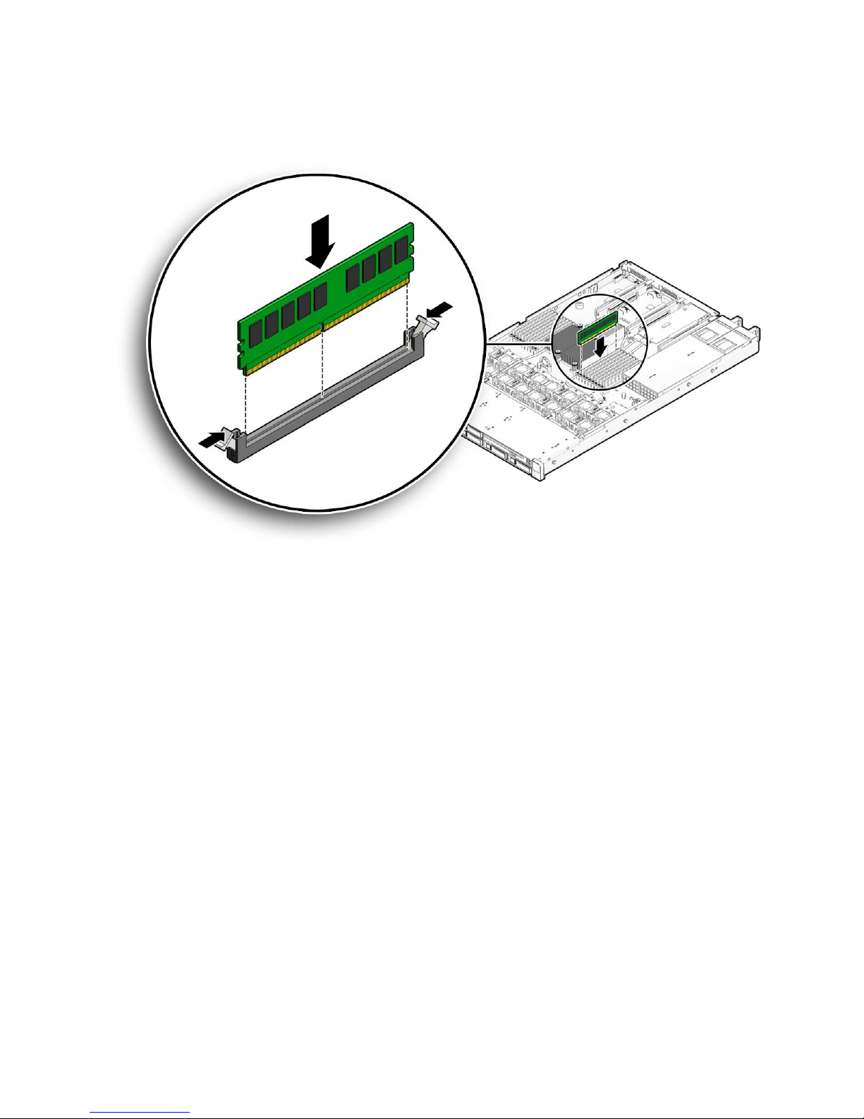
c. Align the DIMM with the connector (
FIGURE 2-4).
Align the notch in the DIMM with the key in the connector. The notch ensures
that the DIMM is oriented correctly.
Page 45
Chapter 2 Installing Server Options 31
FIGURE 2-4 Installing a DIMM
d. Push the DIMM into the connector slot until both ejector levers close,
locking the DIMM in place.
If the DIMM does not easily seat into the connector, verify that the notch in the
DIMM is aligned with the key in the connector as shown in
FIGURE 2-4.Ifthe
notch is not aligned, damage to the DIMM might occur.
e. Repeat Step a through Step d until all DIMMs are installed.
7. Install the top cover.
See “Installing the Server Top Cover” on page 48.
Page 46

32 Sun Fire X4170, X4270, and X4275 Servers Installation Guide • December 2009
Installing a CPU
The server is shipped with at least one preinstalled CPU. The server can support a
maximum of two CPUs. If you ordered a second CPU as an option for the server, the
kit contains a CPU chip and a heatsink with thermal grease pre-applied.
▼ Install the CPU
Caution – CPU options should be installed only by a Sun qualified service
technician.
1. Attach an antistatic wrist strap.
See “ESD Handling Procedure” on page 22.
2. Prepare the server to install options.
See “Preparing the Server to Install Options” on page 22.
3. Unpack the CPU kit.
The kit includes a CPU chip and a heatsink with the thermal grease pre-applied.
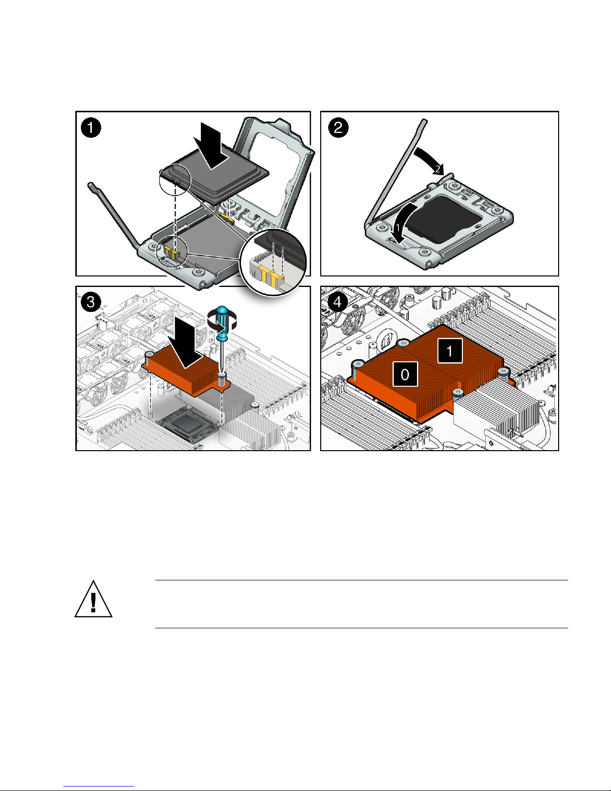
4. Install the CPU (
FIGURE 2-5).
a. Properly orient the CPU with the socket alignment tabs and carefully place
the CPU into the socket [1].
Ensure that the orientation is correct as damage might result if the CPU pins
are not aligned correctly.
Page 47
Chapter 2 Installing Server Options 33
FIGURE 2-5 Installing the CPU
b. Lower the pressure frame.
Ensure that the pressure frame sits flat around the periphery of the CPU.
c. Engage the release lever by rotating it downward and slipping it under the
catch [2].
d. Orient the heatsink so that the two screws line up with the mounting studs
[3].
Caution – When handling the heatsink, be careful not get the thermal grease on
your fingers so as not to transfer the grease to other server components. To do so
could cause component contamination and/or damage.
e. Carefully position the heatsink on the CPU, aligning it with the mounting
posts to reduce movement after it makes initial contact with the layer of
thermal grease [3].
Page 48
34 Sun Fire X4170, X4270, and X4275 Servers Installation Guide • December 2009
Caution – If the heatsink assembly is moved too much during its installation, the
layer of thermal grease may not be distributed evenly, leading to component
damage.
f. Tighten the screws alternately one-half turn until fully seated.
5. Install the top cover.
See “Installing the Server Top Cover” on page 48.
Installing Hard Disk Drives
The following topics are covered in this section:
■ “Server Hard Drive Locations” on page 34
■ “Server Hard Disk Drive Configuration Rules” on page 36
■ “Installing a Hard Disk Drive” on page 37
Server Hard Drive Locations
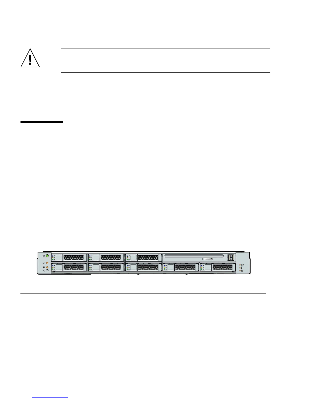
FIGURE 2-6 show the physical drive locations for a Sun Fire X4170 Server with eight 2.5-
inch hard drives.
FIGURE 2-6 Sun Fire X4170 Server Front Panel
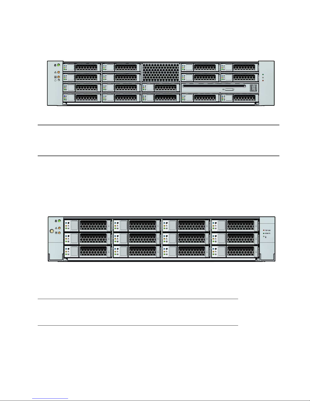
FIGURE 2-7 shows the physical drive locations for the Sun Fire X4270 Server with 16
2.5-inch hard drives.
Figure Legend
HDD1 HDD3 HDD5 DVD drive and USB Connectors (2)
HDD0 HDD2 HDD4 HDD6 HDD7
Page 49
Chapter 2 Installing Server Options 35
FIGURE 2-7 X4270 Server Front Panel
FIGURE 2-8 shows the physical drive locations for the Sun Fire X4275 Server with 12
3.5-inch hard drives.
FIGURE 2-8 Sun Fire X4275 Server Front Panel
Figure Legend
HDD3 HDD7 HDD12 HDD15
HDD2 HDD6 HDD11 HDD14
HDD1 HDD5 HDD9 DVD and USB Connectors (2)
HDD0 HDD4 HDD8 HDD10 HDD13
Figure Legend
HDD2 HDD5 HDD8 HDD11
HDD1 HDD4 HDD7 HDD10
HDD0 HDD3 HDD6 HDD9
Page 50

36 Sun Fire X4170, X4270, and X4275 Servers Installation Guide • December 2009
Server Hard Disk Drive Configuration Rules
TABLE 2-5 defines the number of hard disk drives (HDDs) supported by a given
server type and configuration.
TABLE 2-5 Server Hard Disk Drive (HDD) Configuration Rules
Server
Type/Configuration
SATA
Drives
Supported
SAS Drives
Supported
SSD Drives
Supported Comments
Sun Fire X4170
without HBA
(PCIe) card
6 None 4 Any combination of SATA and solid-state disk (SSD)
HDDs totaling six (6) are supported.
Sun Fire X4170
with LSI 3081E
HBA (PCIe) card
8 8 4 All drives must run off the HBA. Any combination of
these HDD types totaling eight (8) are supported;
however, you cannot mix drive types inside the same
RAID volume.
Sun Fire X4170
with Sun
StorageTek SAS
HBA (PCIe) card
8 8 4 All drives must run off the HBA. Any combination of
these HDD types totaling eight (8) are supported;
however, you cannot mix drive types inside the same
RAID volume.
Sun Fire X4270
without HBA
(PCIe) card
None None None To support HDDs, the X4270 Server must have a PCIe
card installed.
Sun Fire X4270
with LSI 3081E
HBA (PCIe) card
16 16 0 All drives must run off the HBA. Any combination of
these HDD types are supported; however, you cannot
mix drive types inside the same RAID volume.
0Sun Fire X4270
with Sun
StorageTek SAS
HBA (PCIe) card
16 16 8 All drives must run off the HBA. Any combination of
these HDD types are supported; however, you cannot
mix drive types inside the same RAID volume.
Sun Fire X4275
without HBA
(PCIe) card
None None None To support HDDs, the X4275 Server must have a PCIe
card installed.
Sun Fire X4275
with LSI 3081E
HBA (PCIe) card
12 12 0 All drives must run off the HBA. Any combination of
these HDD types are supported; however, you cannot
mix drive types inside the same RAID volume.
Sun Fire X4275
with Sun
StorageTek SAS
HBA (PCIe) card
12 12 8 All drives must run off the HBA. Any combination of
these HDD types are supported; however, you cannot
mix drive types inside the same RAID volume.
Page 51

Chapter 2 Installing Server Options 37
Installing a Hard Disk Drive
To install a hard disk drive, see the following procedure.
▼ Install the Hard Disk Drive
1. Attach an antistatic wrist strap.
See “ESD Handling Procedure” on page 22.
2. Prepare the server to install options.
See “Preparing the Server to Install Options” on page 22.
Note – You do not need to remove the server ’s cover to install a hard drive.
3. Unpack the hard disk drive and place it on an antistatic mat.
4. Install the hardware.
a. Refer to
TABLE 2-5 and verify that your server will support the hard disk
drive you intend to install.
b. Determine the drive slot location for the hard disk drive.
Select the first available hard disk drive location starting with the lowest
numbered slot, HDD0. For example, if the server has two existing hard drives,
install the hard drive in slot HDD2.
c. Remove the hard disk drive filler panel from the server chassis for the
location into which you intend to install the hard drive.
See “Filler Panel Removal and Installation” on page 19.
d. Hard disk drives are physically addressed according to the slot in which
they are installed. See
FIGURE 2-6, FIGURE 2-7 and FIGURE 2-8 for hard drive
locations.
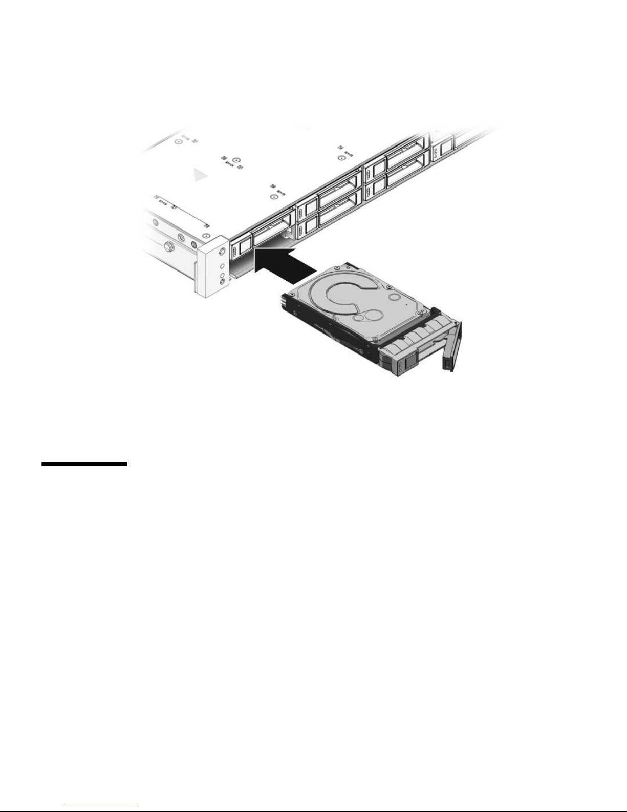
e. Slide the drive into the drive slot until it is fully seated (see
FIGURE 2-9).
Page 52
38 Sun Fire X4170, X4270, and X4275 Servers Installation Guide • December 2009
FIGURE 2-9 Installing a Hard Disk Drive
f. Close the latch to lock the drive in place.
g. Repeat Step a through Step g until all hard drives are installed.
Installing a PCIe Card
The following topics are covered in this section:
■ “PCIe Card Configuration Rules” on page 38
■ “Install a PCIe Card” on page 39
PCIe Card Configuration Rules
The server supports three or six PCIe cards depending on the server model.
■ The Sun Fire X4170 Server supports three PCIe cards.
■ The Sun Fire X4270 and X4275 Servers support six PCIe cards.
Page 53
Chapter 2 Installing Server Options 39
Note – You can install all supported types of PCIe cards into any vacant PCI slot,
with the exception of PCI slot 1. Due to size restrictions, you cannot install a SAS
RAID host bus adapter (HBA) PCIe card into PCI slot 1.
You install the PCIe cards on the servers vertical PCIe risers, which are adjacent to
the PCI slots. For the location of the PCI slots, see
FIGURE 1-5 and FIGURE 1-6.
In addition to the PCIe card, the installation kit includes applicable host bus adapter
installation information that you should reference for additional installation
instructions.
▼ Install a PCIe Card
Caution – This procedure requires that you handle components that are sensitive to
static discharge. This sensitivity can cause the component to fail. To avoid damage,
ensure that you follow antistatic practices as described in “Performing Electrostatic
Discharge and Antistatic Prevention Measures” on page 21.
Caution – Ensure that all power is removed from the server before removing or
installing expansion cards. You must disconnect the power cables before performing
this procedure.
1. Attach an antistatic wrist strap.
See “ESD Handling Procedure” on page 22.
2. Prepare the server to install options.
See “Preparing the Server to Install Options” on page 22.
3. Unpack the PCIe card and place it on an antistatic mat.
4. Determine the PCI slot into which you intend to install the PCIe card.
Note – You can install all supported types of PCIe cards into any vacant PCI slot,
with the exception of PCI slot 1. Due to size restrictions, you cannot install a SAS
RAID host bus adapter (HBA) PCIe card into PCI slot 1.
5. Remove the server back panel crossbar (see
FIGURE 2-10 and FIGURE 2-11).
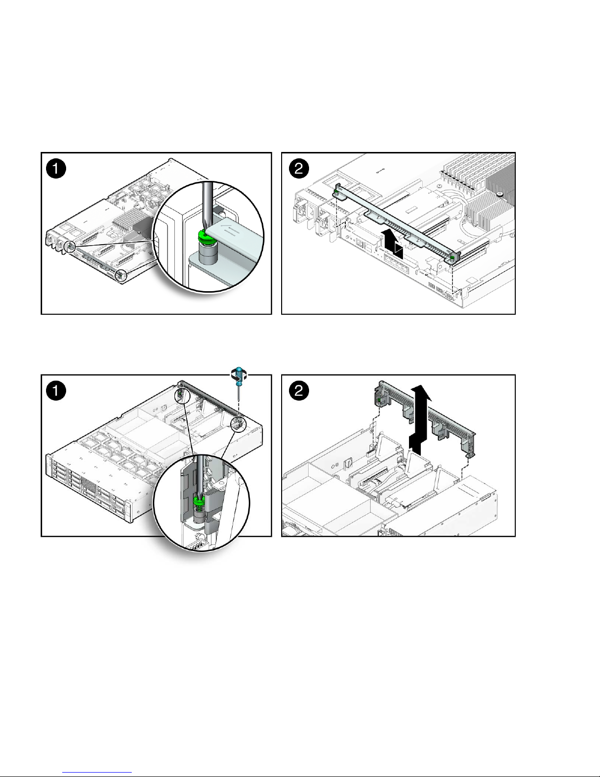
a. Loosen the captive Phillips screw on each end of the back panel crossbar.
Page 54
40 Sun Fire X4170, X4270, and X4275 Servers Installation Guide • December 2009
b. Move the crossbar to the rear of the chassis and lift it up to remove it from
the chassis.
FIGURE 2-10 Removing the Back Panel Crossbar From Sun Fire X4170 Server
FIGURE 2-11 Removing the Back Panel Crossbar From Sun Fire X4270 and X4275 Servers
c. Remove the PCI slot filler panel from the slot in the crossbar into which you
intend to install the PCIe card.
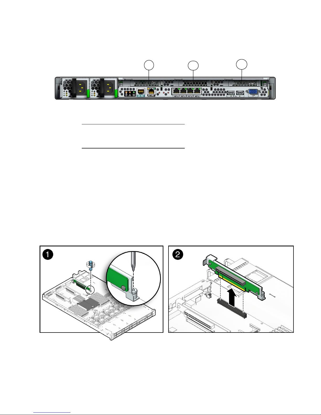
FIGURE 2-12 shows the location of the PCI slot filler panels on the Sun Fire
X4170 Server. The PCI slot filler panels are located in the same area on the Sun
Fire X4270 and X4275 Servers.
Page 55
Chapter 2 Installing Server Options 41
FIGURE 2-12 Location of PCI Slots on the Sun Fire X4170 Server
6. Remove the PCIe riser from the server (see FIGURE 2-13).
a. Using a No. 2 Phillips screwdriver, loosen the captive screw on the end of
the riser.
b. Lift up the riser and any PCIe cards attached to it as a unit.
Each server has three PCIe risers. On the Sun Fire X4170 Server, each PCIe riser
can house only one PCIe card. On the Sun Fire X4270 and X4275 Servers, each
PCIe riser can house two PCIe cards.
FIGURE 2-13 shows a Sun Fire X4170 Server PCIe riser.
FIGURE 2-13 Removing a PCIe Riser
Figure Legend
1 PCI Slot 0
2 PCI Slot 1
3 PCI Slot 2
1
2
3
Page 56
42 Sun Fire X4170, X4270, and X4275 Servers Installation Guide • December 2009
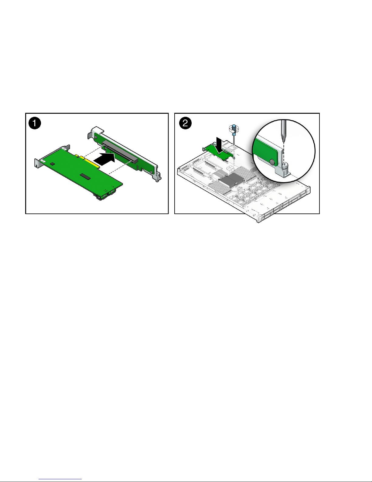
7. Install the PCIe card into the PCIe riser (seeFIGURE 2-14 [1]).
Each server has three PCIe risers. On the Sun Fire X4170 Server, each PCIe riser
can house only one PCIe card. On the Sun Fire X4270 and X4275 Servers, each
PCIe riser can house two PCIe cards.
FIGURE 2-14 Installing a PCIe Card
8. Install the PCIe riser with installed PCIe card into the PCI slot (see FIGURE 2-14
[2]).
a. Lower the PCIe riser and the installed cards into the server.
b. Tighten the captive No. 2 Phillips screw securing the riser to the
motherboard.
c. Install the back panel crossbar.
Slide the crossbar down over the PCIe risers. The crossbar is secured with two
captive Phillips screws.
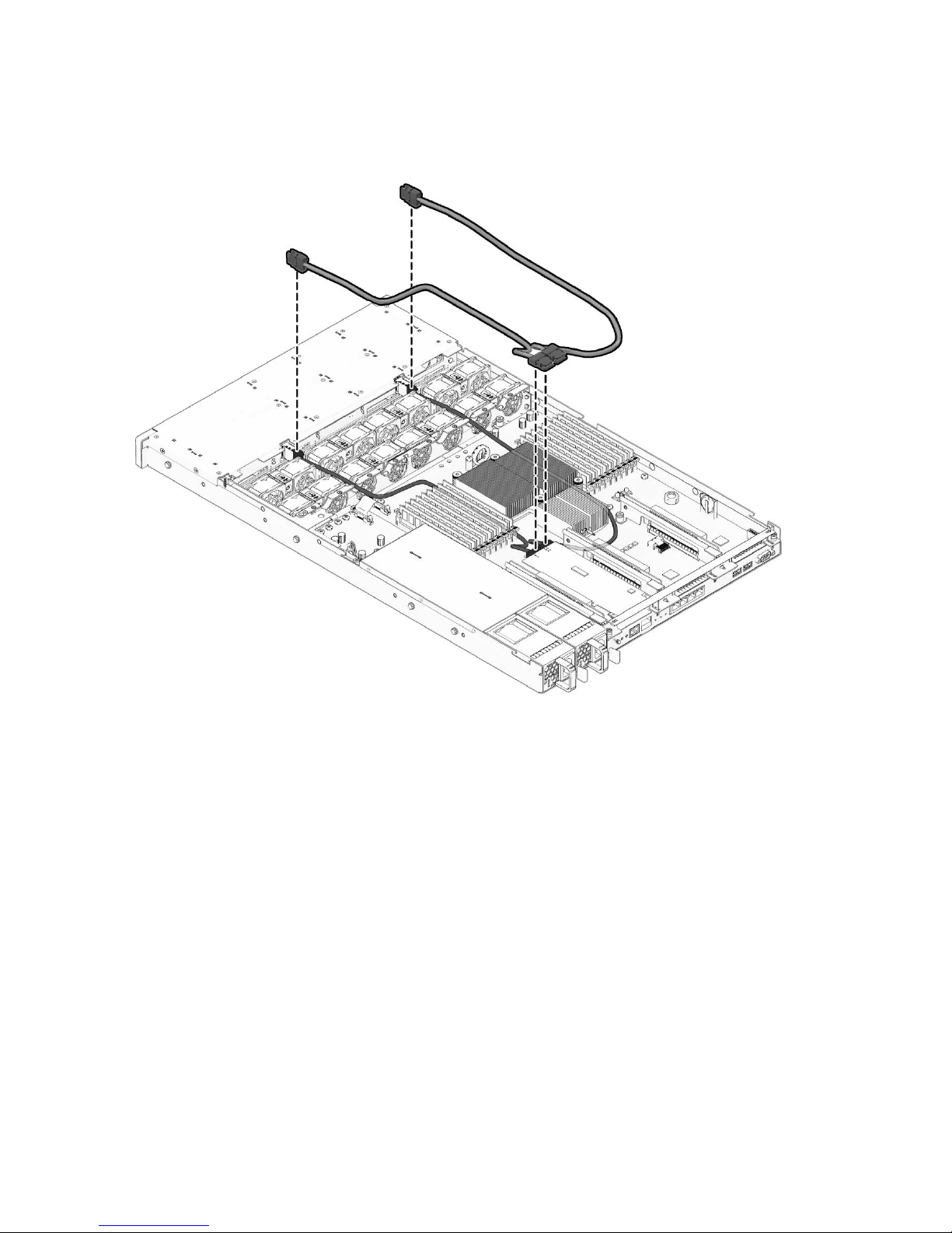
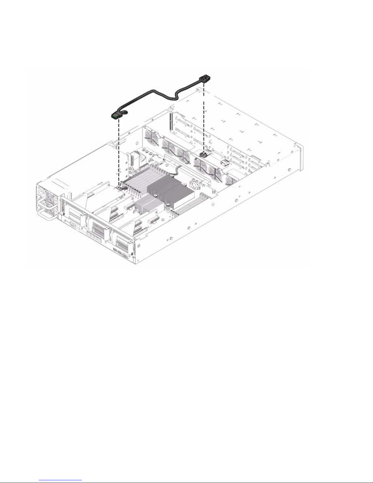
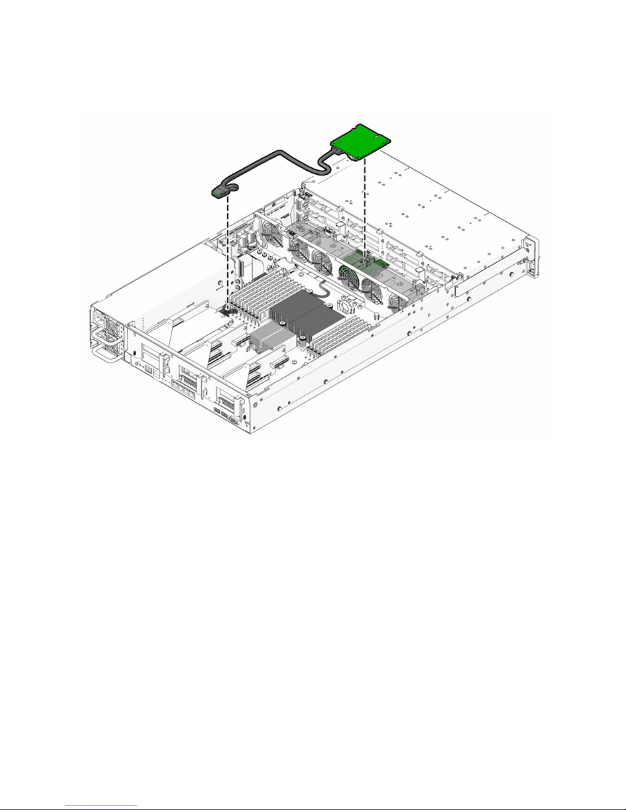
9. If you are installing a SAS RAID host bus adapter (HBA) PCIe card, install and
connect the cables that connect the PCIe card to the hard disk drive cage;
otherwise skip to the next step.
See
FIGURE 2-15 for Sun Fire X4170 Server, FIGURE 2-16 for Sun Fire X4270 Server,
and
FIGURE 2-17 for the Sun Fire X4275 Server.
Page 57
Chapter 2 Installing Server Options 43
FIGURE 2-15 Installing the SAS PCIe/Hard Disk Drive Cage Cable Into the Sun Fire X4170 Server
Page 58
44 Sun Fire X4170, X4270, and X4275 Servers Installation Guide • December 2009
FIGURE 2-16 Installing the SAS PCIe/Hard Disk Drive Cage Cable in the Sun Fire X4270 Server
Page 59
Chapter 2 Installing Server Options 45
FIGURE 2-17 Installing the SAS PCIe/Hard Disk Drive Cage Cable in the Sun Fire X4275 Server
10. For additional PCIe card installation requirements, refer to the installation
information in the PCIe card shipping kit.
11. Install the server top cover.
See “Installing the Server Top Cover” on page 48.
Page 60

46 Sun Fire X4170, X4270, and X4275 Servers Installation Guide • December 2009
Installing a Power Supply
If the server has only one power supply, you can install a second power supply for
redundancy.
▼ Install a Power Supply
1. Attach an antistatic wrist strap.
See “ESD Handling Procedure” on page 22.
2. Prepare the server to install options.
See “Preparing the Server to Install Options” on page 22.
Note – You do not need to remove the server ’s cover to install a power supply.
3. Unpack the power supply and place it on an antistatic mat.
4. Install the power supply.
a. Remove the filler panel from the server’s power supply bay.
See “Filler Panel Removal and Installation” on page 19.
b. Align the power supply with the empty power supply chassis bay.
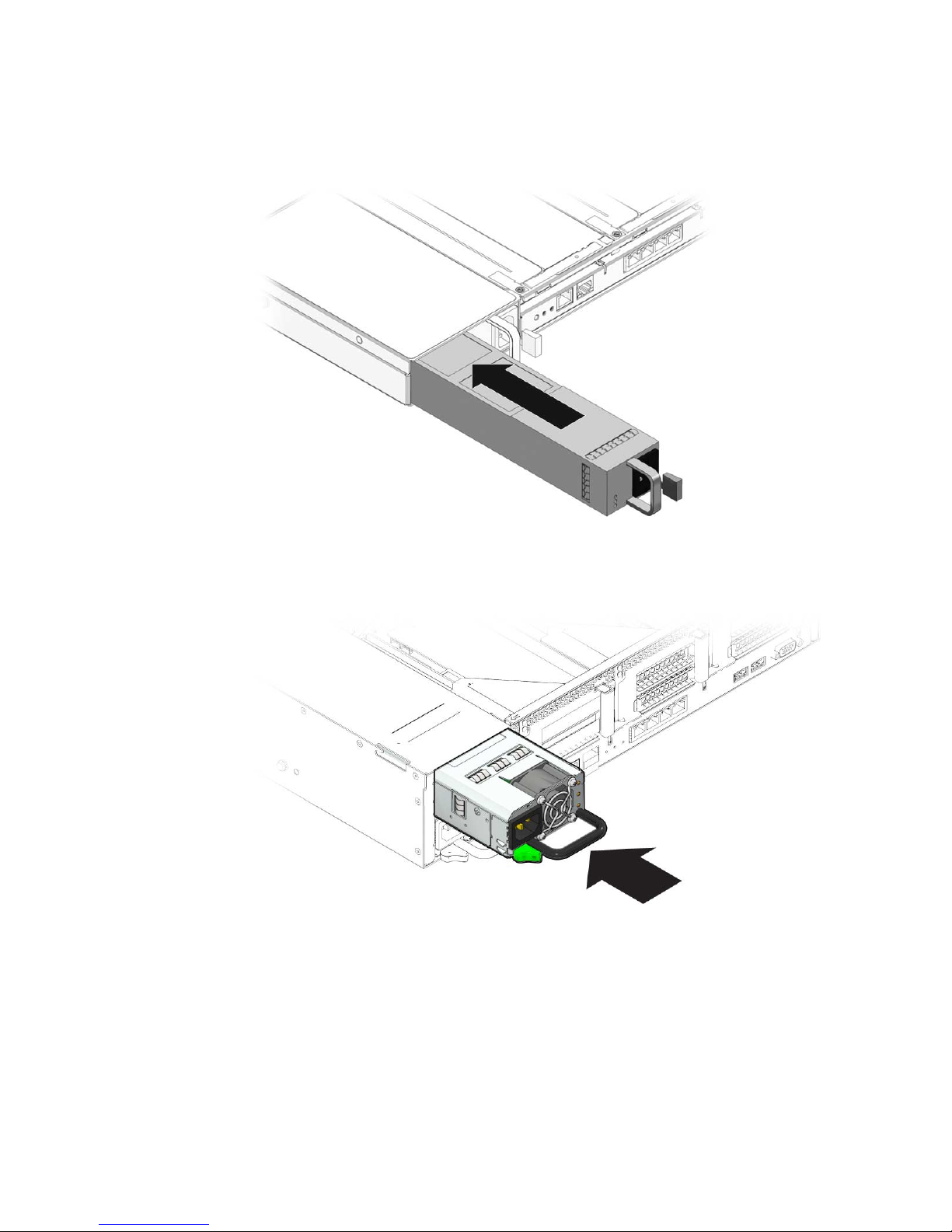
c. Slide the power supply into the bay until it is fully seated (see
FIGURE 2-18
and FIGURE 2-19).
Page 61
Chapter 2 Installing Server Options 47
FIGURE 2-18 Installing a Power Supply Into a Sun Fire X4170 Server
FIGURE 2-19 Installing a Power Supply Into a Sun Fire X4270 or X4275 Server
Page 62

48 Sun Fire X4170, X4270, and X4275 Servers Installation Guide • December 2009
Installing the Server Top Cover
After you have installed the optional components, you must reinstall the top cover
onto the server.
▼ Install the Server Top Cover
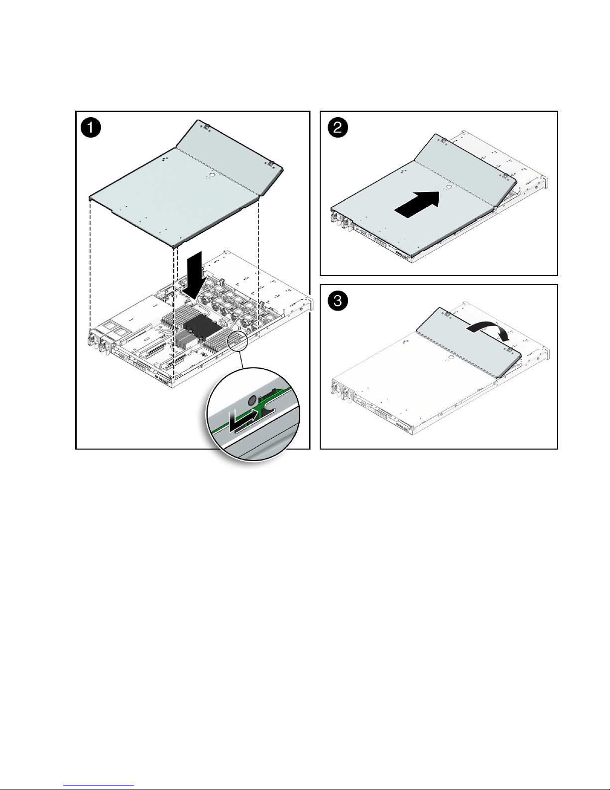
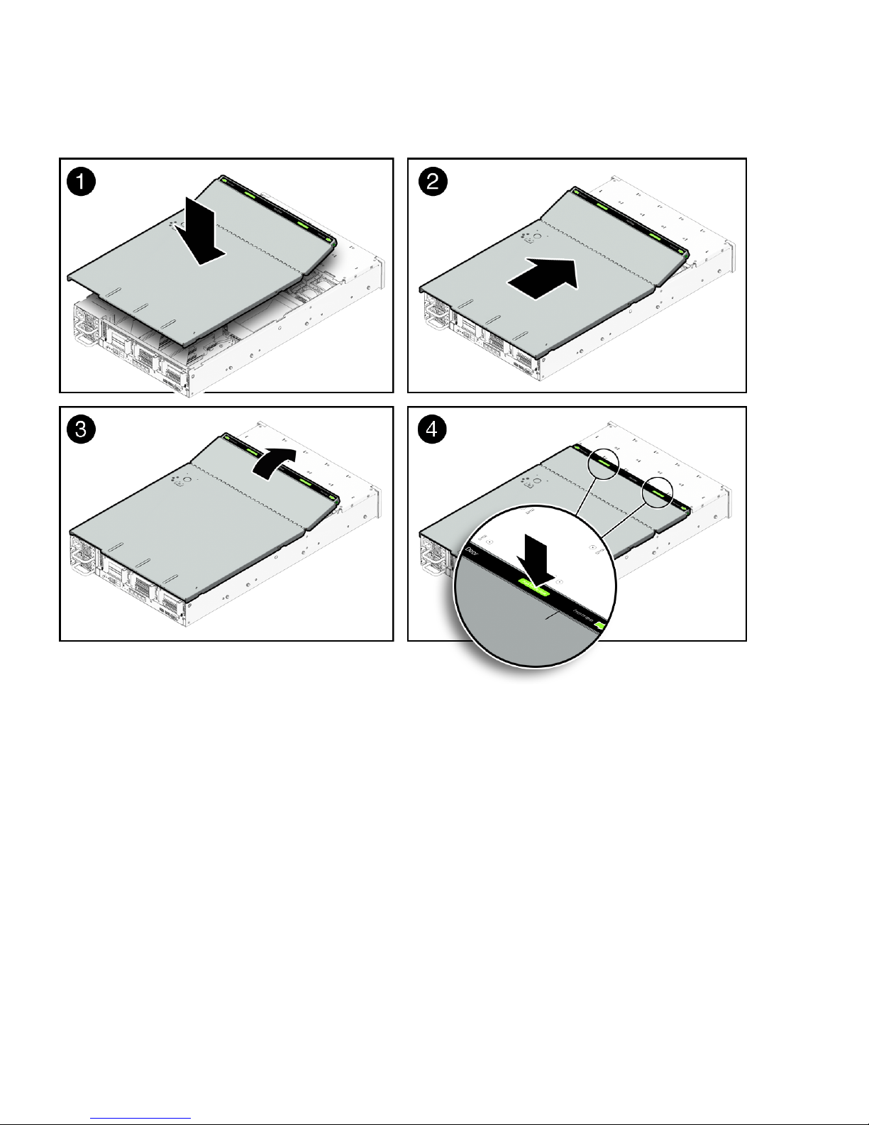
1. Place the top cover on the chassis.
Set the cover down so that it hangs over the rear of the server by about 1 inch
(25.4 mm) (see
FIGURE 2-20 [1] or FIGURE 2-21 [1]).
2. Slide the top cover forward until it cover side latches engage [1 and 2].
3. To close the fan cover, press down on the fan cover with both hands [3].
Page 63
Chapter 2 Installing Server Options 49
FIGURE 2-20 Installing the Top Cover on the Sun Fire X4170 and X4270 Servers
Page 64
50 Sun Fire X4170, X4270, and X4275 Servers Installation Guide • December 2009
FIGURE 2-21 Installing the Top Cover on the Sun Fire X4275 Server
Page 65

51
CHAPTER
3
Installing the Server Into a Rack
With Slide-Rails
This chapter describes how to place the server into a rack using the rail assembly in
the rackmount kit. Perform this procedure if the rail assembly is purchased.
This chapter includes the following topics:
■ “Before You Begin” on page 51
■ “Checking Rack Compatibility” on page 53
■ “Disassembling Slide-Rails” on page 54
■ “Installing the Mounting Brackets Onto the Server” on page 56
■ “Attaching the Slide-Rail Assemblies to the Rack” on page 58
■ “Installing the Server Into the Slide-Rail Assemblies” on page 61
■ “Installing the Cable Management Arm” on page 65
■ “Verifying Operation of the Slide-Rails and CMA” on page 72
Note – In this guide, the term rack means either an open rack or a closed cabinet.
Before You Begin
Read the following overview and see the service label on the top cover before you
begin to install the server into a rack.
Page 66

52 Sun Fire X4170, X4270, and X4275 Servers Installation Guide • December 2009
Server Installation Process Overview
To install your server into a four-post rack using the slide-rail and cable
management arm options, perform the following tasks in the order listed.
1. “Checking Rack Compatibility” on page 53
2. “Disassembling Slide-Rails” on page 54
3. “Installing the Mounting Brackets Onto the Server” on page 56
4. “Installing the Cable Management Arm” on page 65
5. “Verifying Operation of the Slide-Rails and CMA” on page 72
6. “Connecting the Cables” on page 74
Rail Assemblies
The server might include either tool-less or bolt-on rail assemblies in rackmount kits.
Instructions for both types are included in this chapter.
Service Label
Refer to the service label on the server top cover for instructions on how to install
your server into a four-post rack, using the slide-rail and cable management arm
options. The service label includes instructions for both tool-less and bolt-on rail
assemblies.
Page 67

Chapter 3 Installing the Server Into a Rack With Slide-Rails 53
Checking Rack Compatibility
Check that your rack is compatible with the slide-rail and cable management arm
(CMA) options. The optional slide-rails are compatible with a wide range of
equipment racks that meet the following standards.
Caution – Always load equipment into a rack from the bottom up so that it will not
become top-heavy and tip over. Deploy your rack’s anti-tip bar to prevent the rack
from tipping during equipment installation.
TABLE 3-1 Rack Compatibility
Item Requirement
Structure Four-post rack (mounting at both front and rear).
Two-post racks are not compatible.
Rack horizontal opening and unit
vertical pitch
Conforms to ANSI/EIA 310-D-1992 or IEC 60927
standards.
Distance between front and rear
mounting planes
Minimum 610 mm and maximum 915 mm
(24 inches to 36 inches).
Clearance depth in front of front
mounting plane
Distance to front cabinet door is at least 25.4 mm
(1 inch).
Clearance depth behind front
mounting plane
Distance to rear cabinet door is at least 800 mm (31.5
inches) with the cable management arm, or 700 mm
(27.5 inches) without the cable management arm.
Clearance width between front and
rear mounting planes
Distance between structural supports and cable
troughs is at least 456 mm (18 inches).
Server dimensions See
TABLE 3-1 for server dimensions.
Page 68

54 Sun Fire X4170, X4270, and X4275 Servers Installation Guide • December 2009
Caution – Elevated Operating Ambient Temperature: If the server is installed in a
closed or multi-unit rack assembly, the operating ambient temperature of the rack
environment might be greater than room ambient temperature. Therefore,
consideration should be given to installing the equipment in an environment
compatible with the maximum ambient temperature (Tma) specified for the server.
For server environmental requirements, see “Environmental Requirements” on
page 15.
Caution – Reduced Air Flow: Installation of the equipment in a rack should be
such that the amount of air flow required for safe operation of the equipment is not
compromised.
Caution – Mechanical Loading: Mounting of the equipment in the rack should be
such that a hazardous condition is not achieved due to uneven mechanical loading.
Caution – Circuit Overloading: Consideration should be given to the connection of
the equipment to the supply circuit and the effect that overloading of the circuits
might have on over-current protection and supply wiring. Appropriate
consideration of equipment nameplate power ratings should be used when
addressing this concern.
Caution – Reliable Earthing: Reliable earthing of rackmounted equipment should
be maintained. Particular attention should be given to supply connections other than
direct connections to the branch circuit (for example, use of power strips).
Disassembling Slide-Rails
Complete one of the following procedures before installation:
■ “Disassemble Bolt-On Slide-Rails” on page 55
■ “Disassemble Tool-less Slide-Rails” on page 56
Page 69
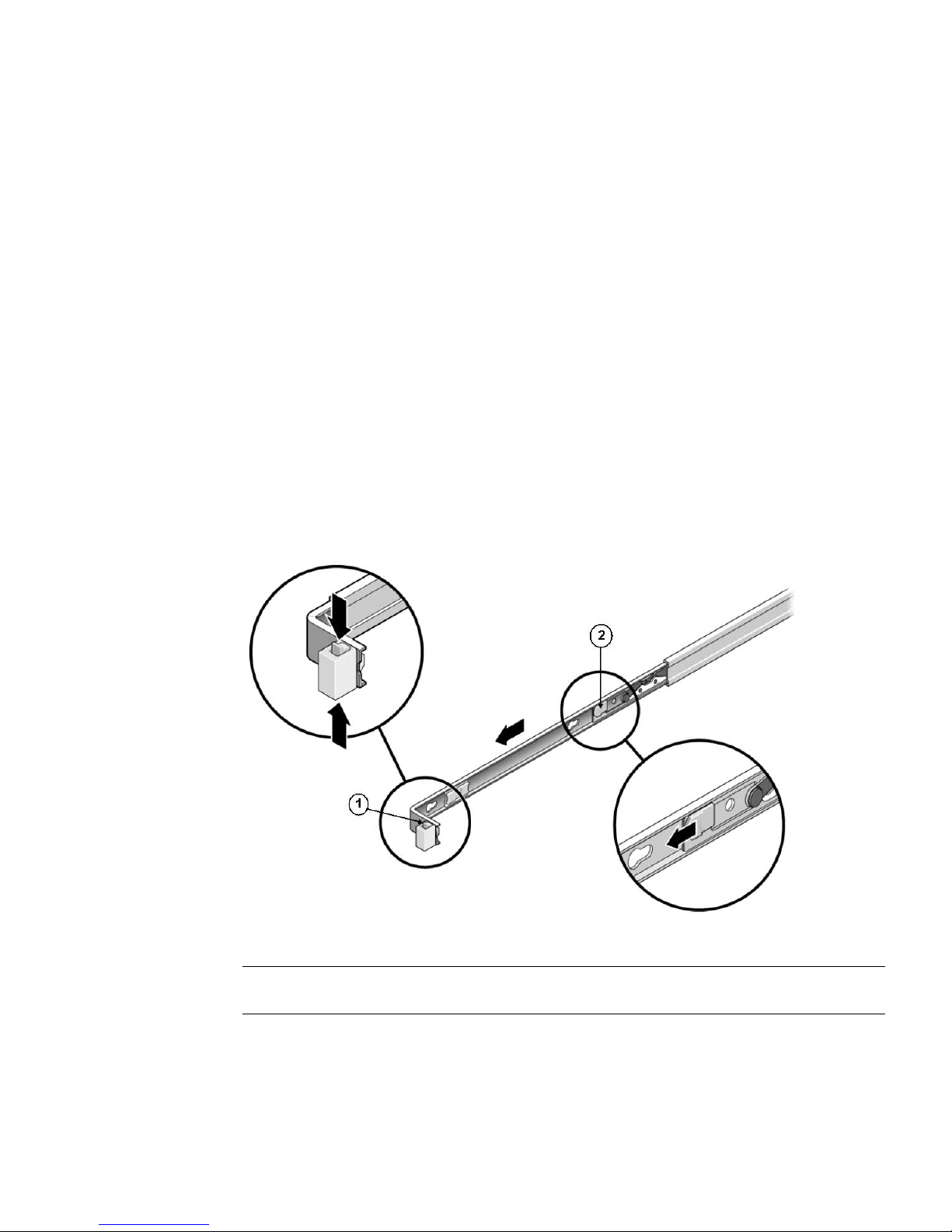
Chapter 3 Installing the Server Into a Rack With Slide-Rails 55
▼ Disassemble Bolt-On Slide-Rails
To remove the mounting brackets from the bolt-on slide-rail assemblies:
1. Unpack the slide-rails.
2. Locate the slide-rail lock at the front of one of the slide-rail assemblies, as
shown in
FIGURE 3-1.
3. Squeeze and hold the tabs at the top and bottom of the lock while you pull the
mounting bracket out of the slide-rail assembly until it reaches the stop (see
FIGURE 3-1).
4. Push the mounting bracket release button toward the front of the mounting
bracket, as shown in
FIGURE 3-1, and simultaneously withdraw the mounting
bracket from the slide-rail assembly.
5. Repeat for the remaining slide-rail assembly.
FIGURE 3-1 Disassembling the Bolt-On Slide-Rail Before Installation
Figure Legend
1 Slide-rail lock
2 Mounting bracket release button
Page 70

56 Sun Fire X4170, X4270, and X4275 Servers Installation Guide • December 2009
▼ Disassemble Tool-less Slide-Rails
To remove the mounting brackets from the tool-less slide-rail assemblies, refer to the
installation card instructions included with the rackmount kit.
Installing the Mounting Brackets Onto
the Server
You must install the mounting brackets onto the server before you can rackmount
the server.
▼ Install Mounting Brackets
To install the mounting brackets onto the sides of the server:
1. Position a mounting bracket against the chassis so that the slide-rail lock is at
the server front, and the four keyed openings on the mounting bracket are
aligned with the four locating pins on the side of the chassis.
Page 71
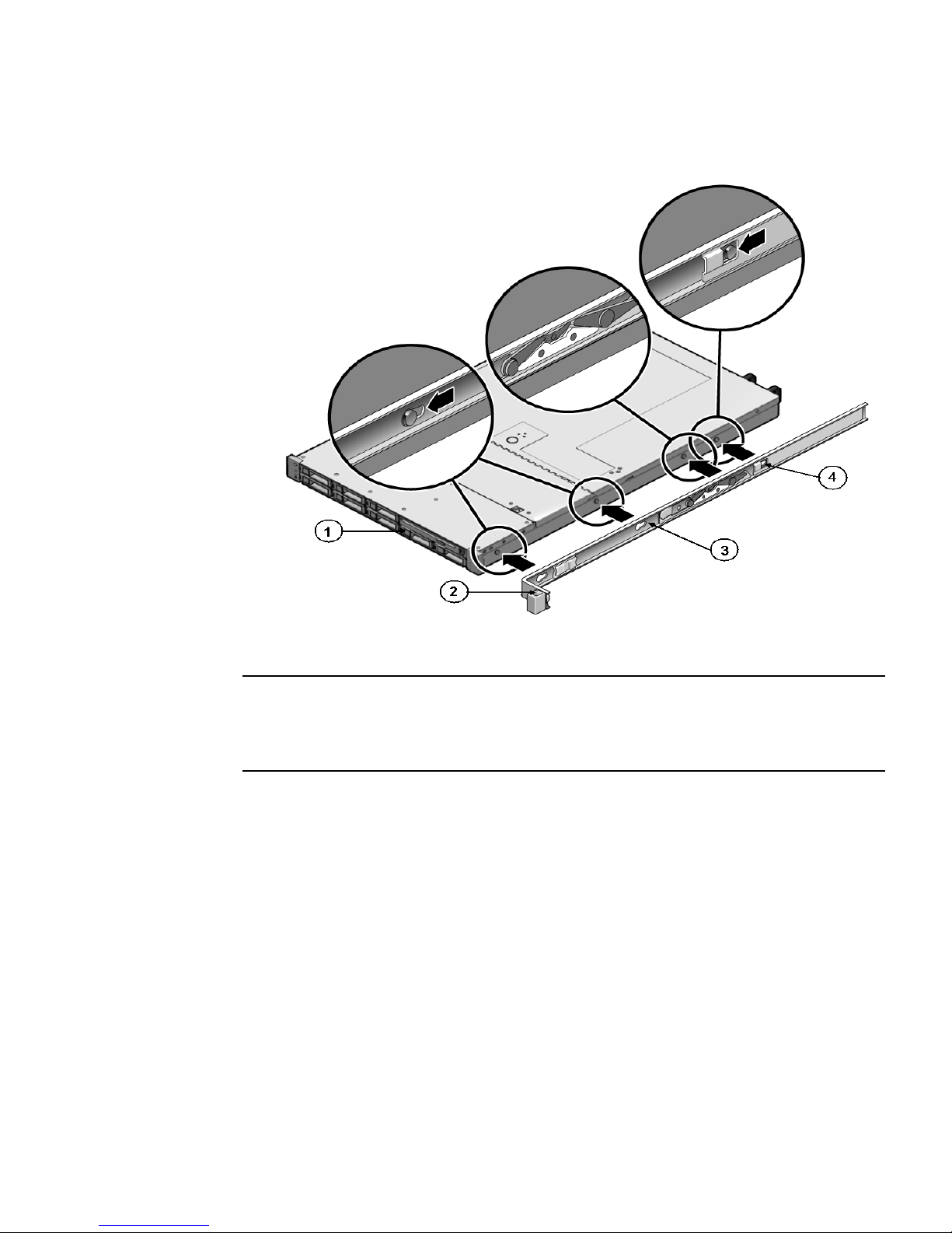
Chapter 3 Installing the Server Into a Rack With Slide-Rails 57
FIGURE 3-2 Aligning the Mounting Bracket With the Server Chassis
2. With the heads of the four chassis locating pins protruding though the four
keyed openings in the mounting bracket, pull the mounting bracket toward the
front of the chassis until the mounting bracket clip locks into place with an
audible click (see
FIGURE 3-2).
3. Verify that the rear locating pin has engaged the mounting bracket clip (see
FIGURE 3-2).
4. Repeat to install the remaining mounting bracket on the other side of the
server.
Figure Legend
1 Chassis front
2 Slide-rail lock
3 Mounting bracket
4 Mounting bracket clip
Page 72

58 Sun Fire X4170, X4270, and X4275 Servers Installation Guide • December 2009
Attaching the Slide-Rail Assemblies to
the Rack
Complete one of the following procedures to attach the slide-rail assemblies to the
rack:
■ “Attach Bolt-On Slide-Rail Assemblies” on page 58
■ “Attach Tool-less Slide-Rail Assemblies” on page 61
▼ Attach Bolt-On Slide-Rail Assemblies
To attach bolt-on slide-rail assemblies to the rack:
1. Position a slide-rail assembly in your rack so that the brackets at each end of
the slide-rail assembly are on the outside of the front and rear rack posts (see
FIGURE 3-3).
2. Attach the slide-rail assembly to the rack posts, but do not tighten the screws
completely.
Choose one of the following methods to attach the slide-rails. The method you
use varies, depending on the type of rack:
■ If your rack has threaded mounting holes in the rack posts, first determine
whether the threads are metric or standard, then insert the correct mounting
screws through the slide-rail brackets and into the threaded holes.
■ If your rack does not have threaded mounting holes, insert the mounting
screws through both the slide-rail brackets and rack posts, then secure them
with the caged nuts.
Page 73
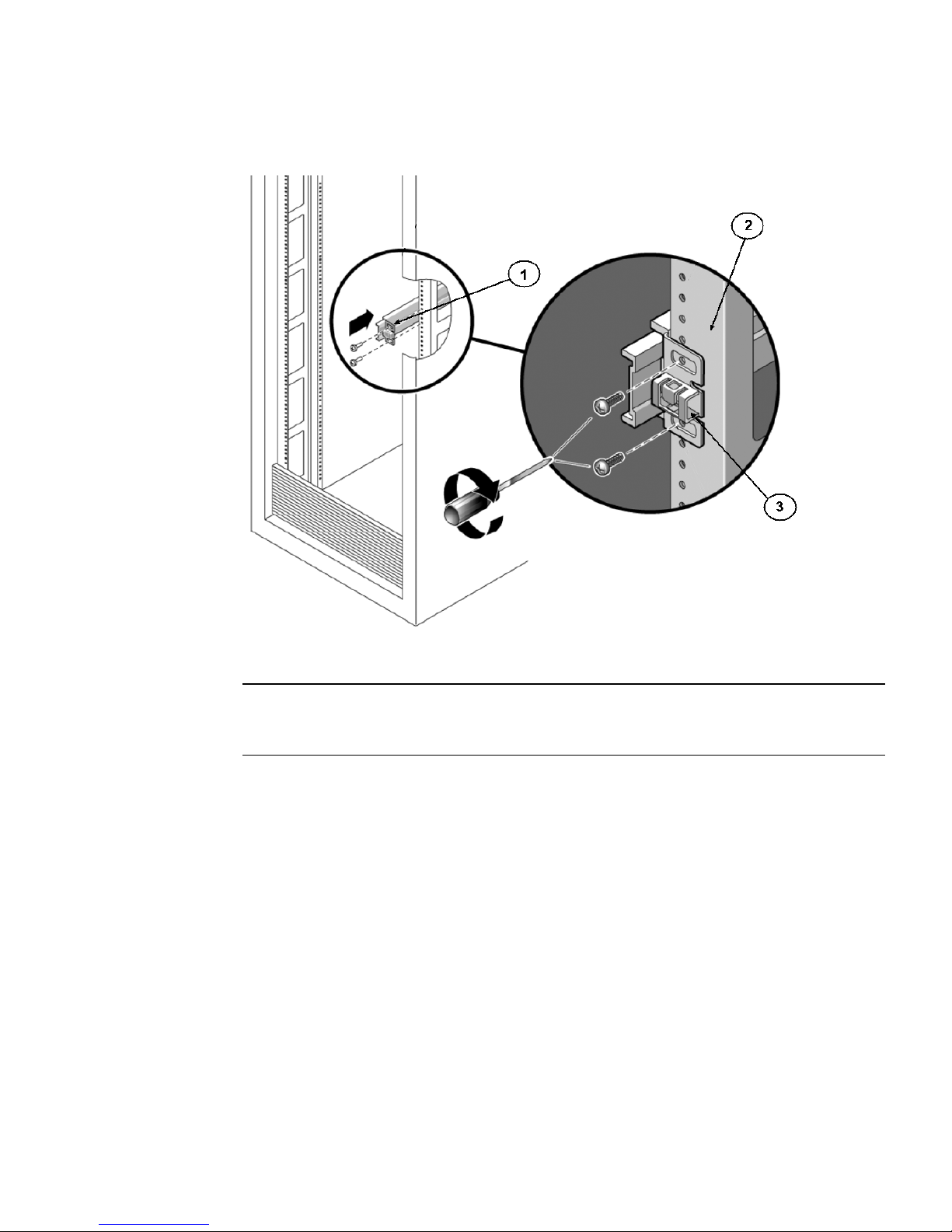
Chapter 3 Installing the Server Into a Rack With Slide-Rails 59
FIGURE 3-3 Attaching Slide-Rail Assembly to Rack Post
3. Repeat Step 1 and Step 2 for the remaining slide-rail assembly.
4. From the front of the rack, set the proper width of the rails with the spacer (see
FIGURE 3-4).
Figure Legend
1 Sllide-rail assembly
2 Rack post
3 Slide-raid assembly bracket on outside of rack post
Page 74
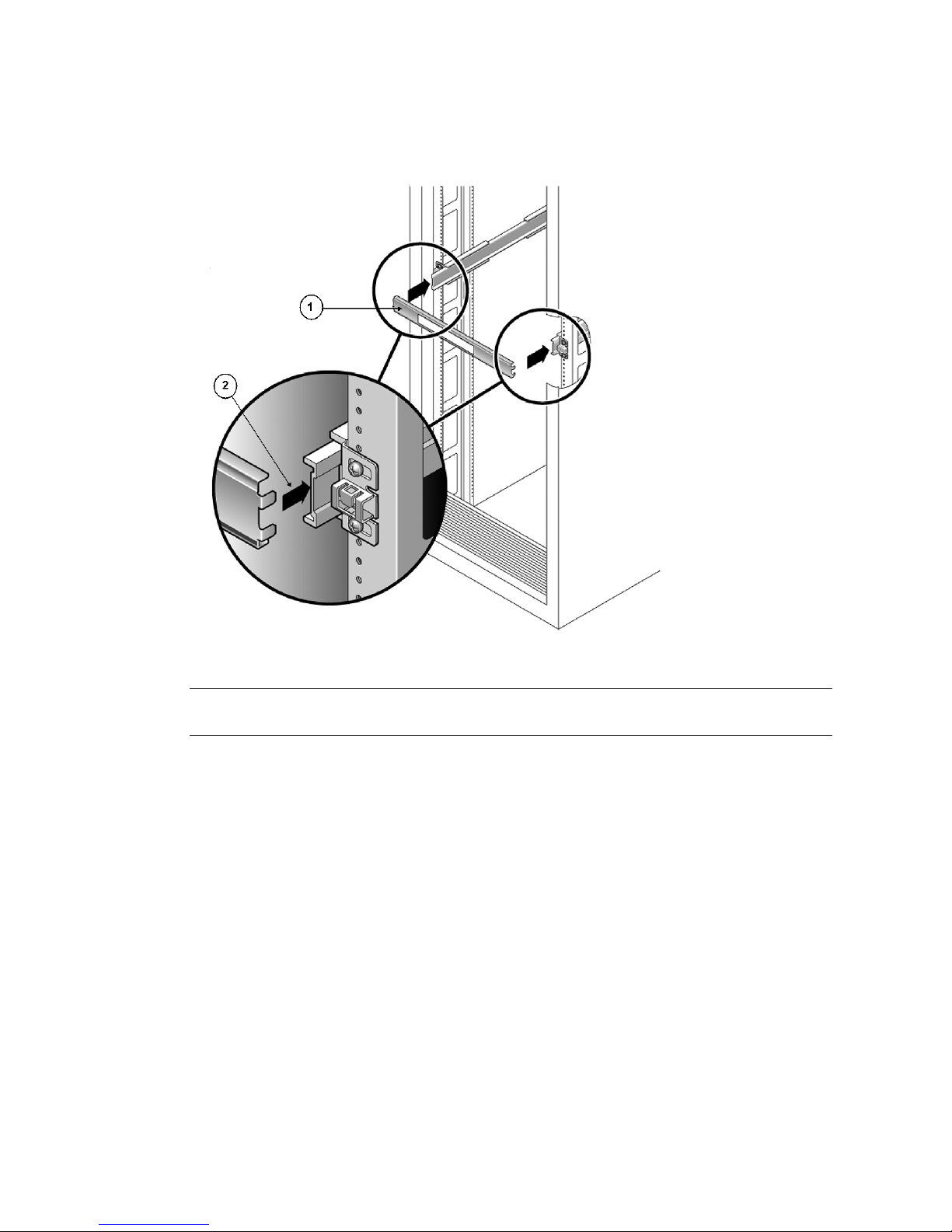
60 Sun Fire X4170, X4270, and X4275 Servers Installation Guide • December 2009
FIGURE 3-4 Setting the Rail Width
5. Tighten the screws on both brackets.
6. Remove the spacer and confirm that the rails are attached tightly to the rack.
7. Repeat Step 4 through Step 6 for the side-rail assembly at the rear of the rack.
Figure Legend
1 Rail-width spacer
2 Attaching the spacer to the rails
Page 75
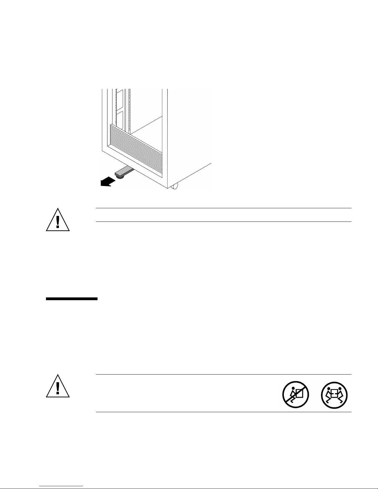
Chapter 3 Installing the Server Into a Rack With Slide-Rails 61
8. If available, extend the anti-tip bar at the bottom of the rack (see FIGURE 3-5).
FIGURE 3-5 Extending the Anti-tip Bar
Caution – If your rack does not have an anti-tip bar, the rack could tip over.
▼ Attach Tool-less Slide-Rail Assemblies
To attach tool-less slide-rail assemblies to the rack, refer to the installation card
instructions included with the rackmount kit.
Installing the Server Into the Slide-Rail
Assemblies
Use this procedure to install the server chassis, with mounting brackets, into the
slide-rail assemblies that are mounted to the rack.
Caution – This procedure requires a minimum of two
people because of the weight of the server. Attempting this
procedure alone could result in equipment damage or
personal injury.
Page 76

62 Sun Fire X4170, X4270, and X4275 Servers Installation Guide • December 2009
Caution – Always load equipment into a rack from the bottom up so that it will not
become top-heavy and tip over. Extend your rack’s anti-tip bar to prevent the rack
from tipping during equipment installation.
▼ Install Server Into the Slide-Rail Assemblies
1. Push the slide-rails into the slide-rail assemblies in the rack as far as possible.
2. Raise the server so that the rear ends of the mounting brackets are aligned with
the slide-rail assemblies that are mounted in the equipment rack (see
FIGURE 3-6).
3. Insert the mounting brackets into the slide-rails, then push the server into the
rack until the mounting brackets encounter the slide-rail stops (approximately
12 inches, or 30 cm).
Page 77
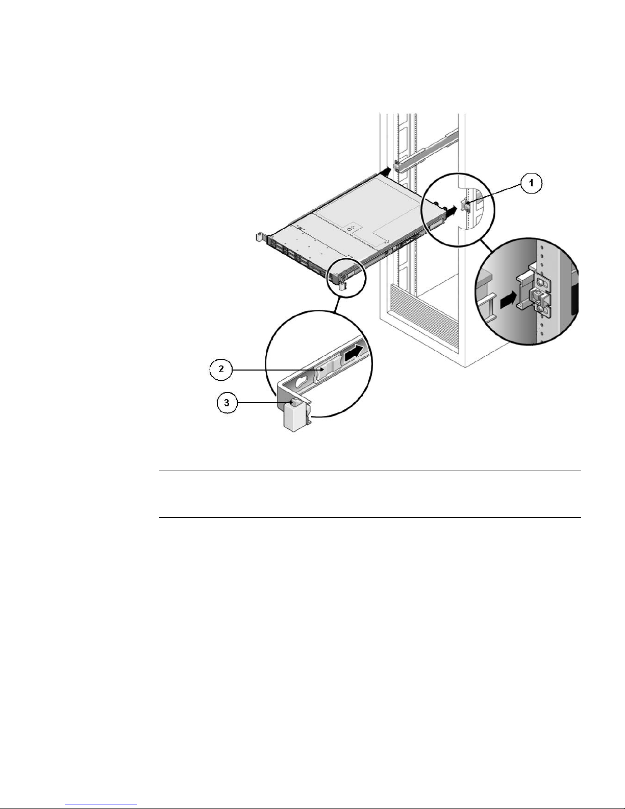
Chapter 3 Installing the Server Into a Rack With Slide-Rails 63
FIGURE 3-6 Inserting the Server With Mounting Brackets Into the Slide-Rails
4. Simultaneously push and hold the slide-rail release buttons on each mounting
bracket while you push the server into the rack (see
FIGURE 3-7). Continue
pushing until the slide-rail locks (on the front of the mounting brackets)
engage the slide-rail assemblies.
You will hear an audible click.
Figure Legend
1 Inserting mounting bracket into slide rail
1 Sllide-rail release button
1 Slide-rail lock
Page 78
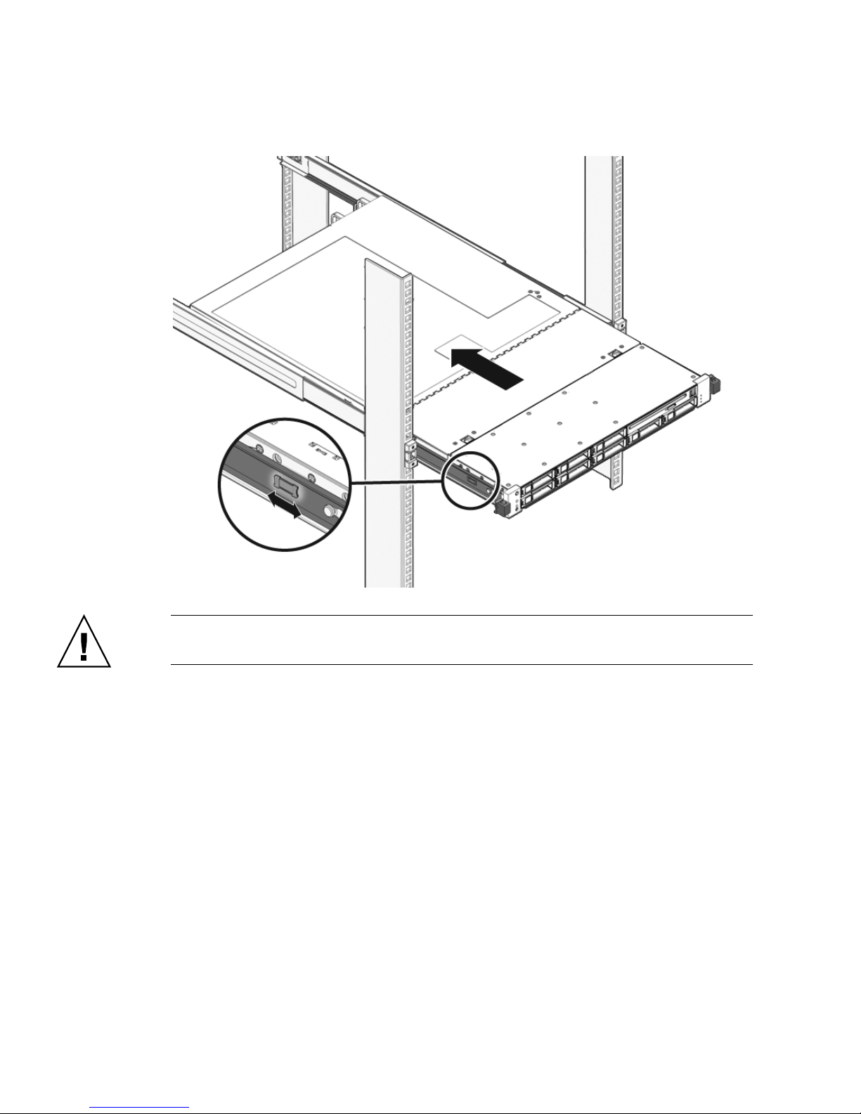
64 Sun Fire X4170, X4270, and X4275 Servers Installation Guide • December 2009
FIGURE 3-7 Sliding the Server Back Into the Rack
Caution – Verify that the server is securely mounted in the rack and that the slide-
rail locks are engaged with the mounting brackets before continuing.
Page 79
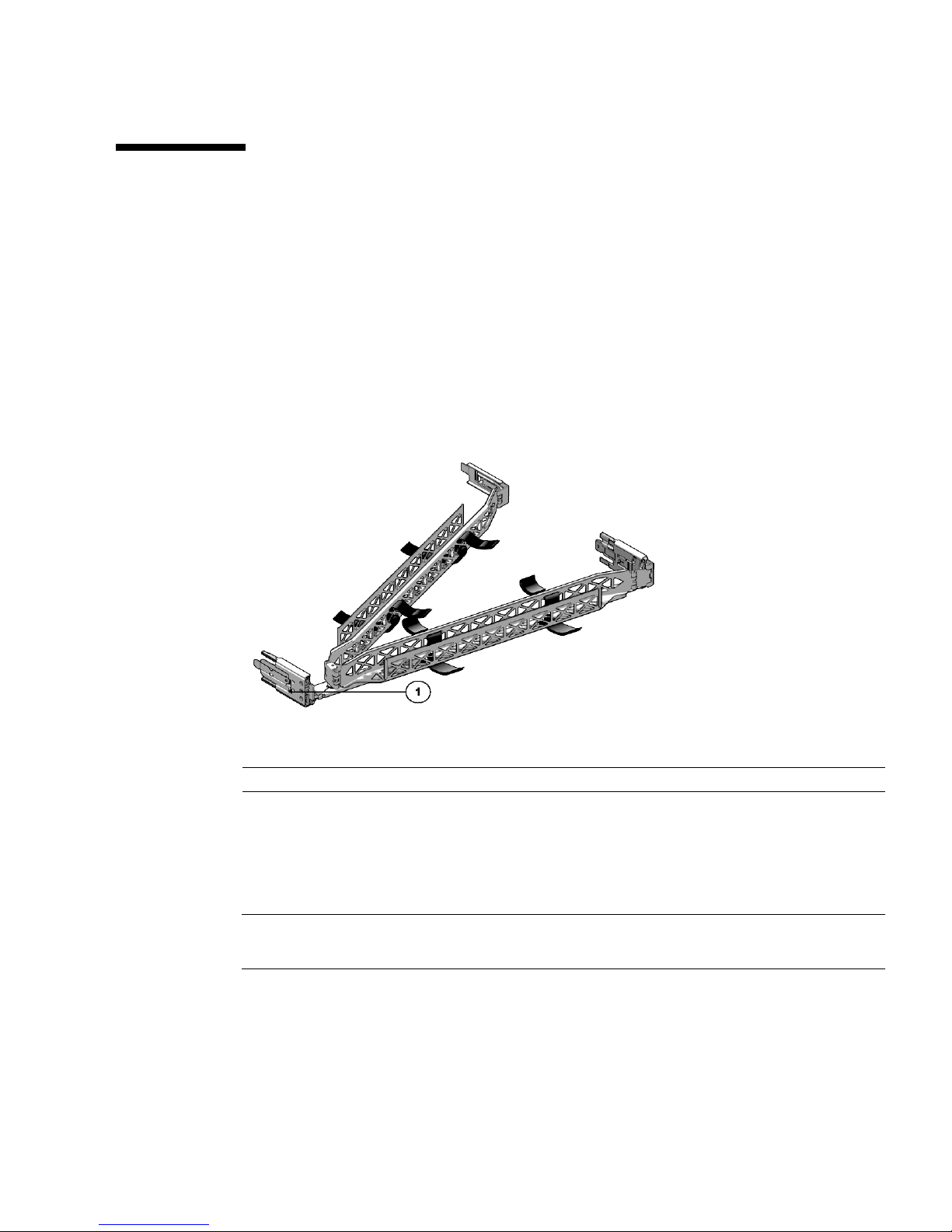
Chapter 3 Installing the Server Into a Rack With Slide-Rails 65
Installing the Cable Management Arm
The cable management arm (CMA) is an optional assembly that you can use to route
the server cables in the rack.
▼ Install Cable Management Arm
Use this procedure to install the optional CMA (see FIGURE 3-8).
FIGURE 3-8 Cable Management Arm (CMA)
1. Unpack the CMA parts.
2. Take the CMA to the back of the equipment rack and ensure that you have
adequate room to work around the back of the server.
Note – References to “left” or “right” in this procedure assume that you are facing
the back of the equipment rack.
3. Remove tape to separate parts.
The CMA rail extension might be taped to the CMA arm.
Figure Legend
1 CMA rail extension
Page 80
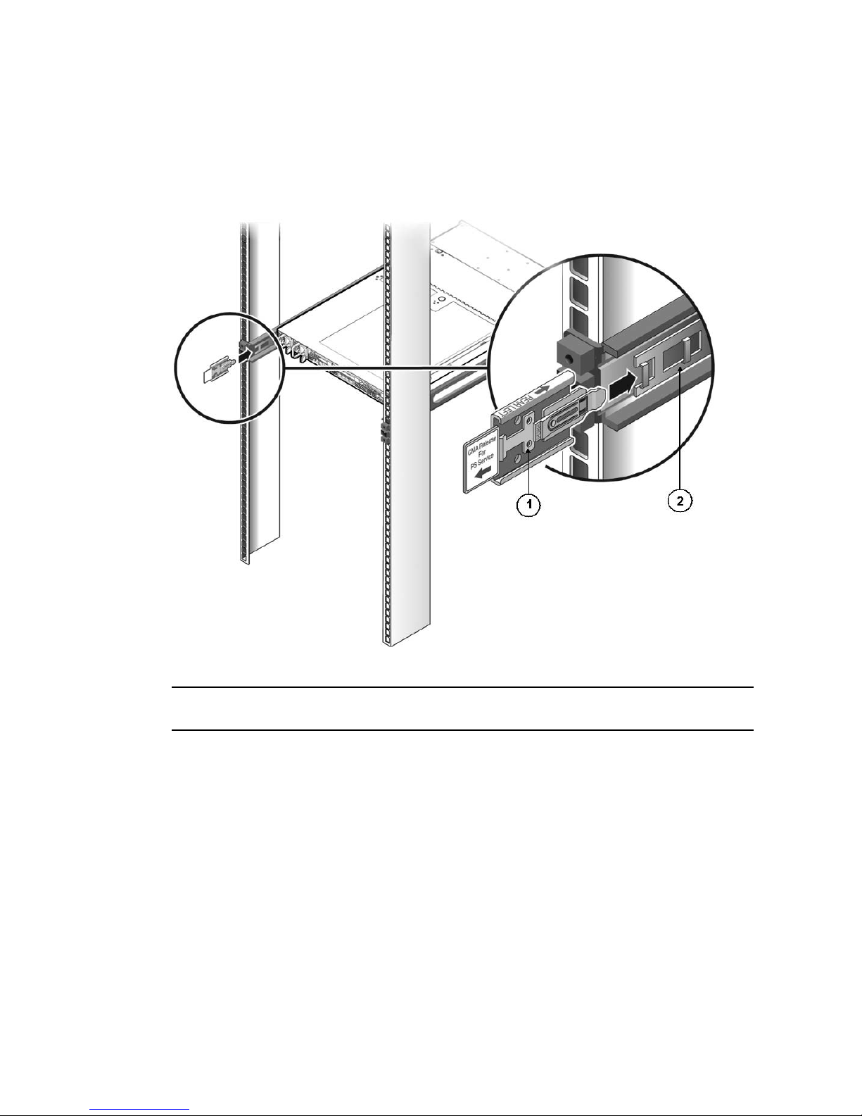
66 Sun Fire X4170, X4270, and X4275 Servers Installation Guide • December 2009
4. Attach the CMA rail extension into the left slide-rail until the extension locks
into place with an audible click (see
FIGURE 3-9).
FIGURE 3-9 Inserting the CMA Rail Extension Into the Back of the Left Slide-Rail
Figure Legend
1 CMA rail extension
2 Left slide-rail
Page 81
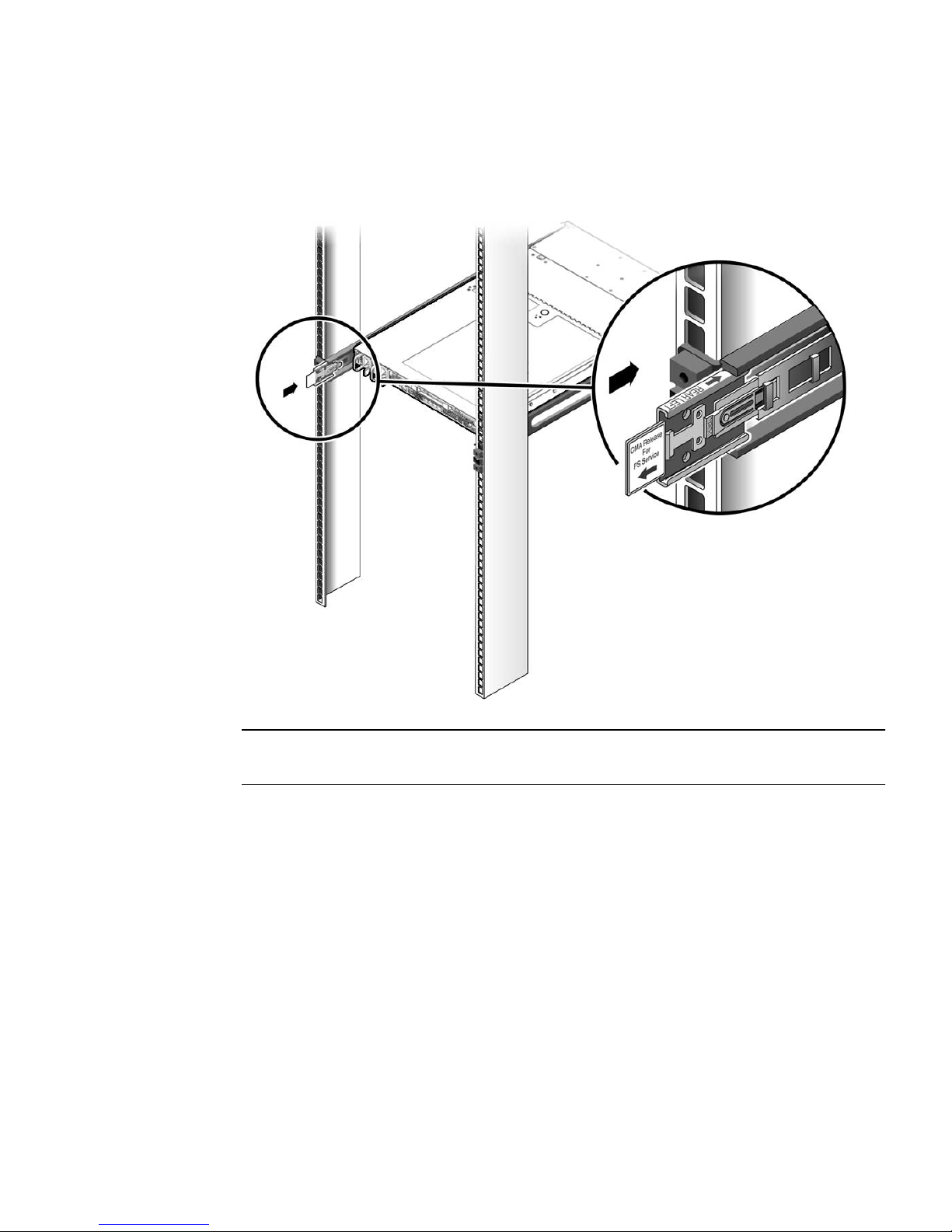
Chapter 3 Installing the Server Into a Rack With Slide-Rails 67
5. Verify that the CMA rail extension engages the slide-rail (see FIGURE 3-10).
FIGURE 3-10 Engaging the CMA Rail Extension With the Left Slide-Rail
Note – Support the CMA in the remaining installation steps. Do not allow the arm
to hang by its own weight until it is secured by all three attachment points.
Page 82
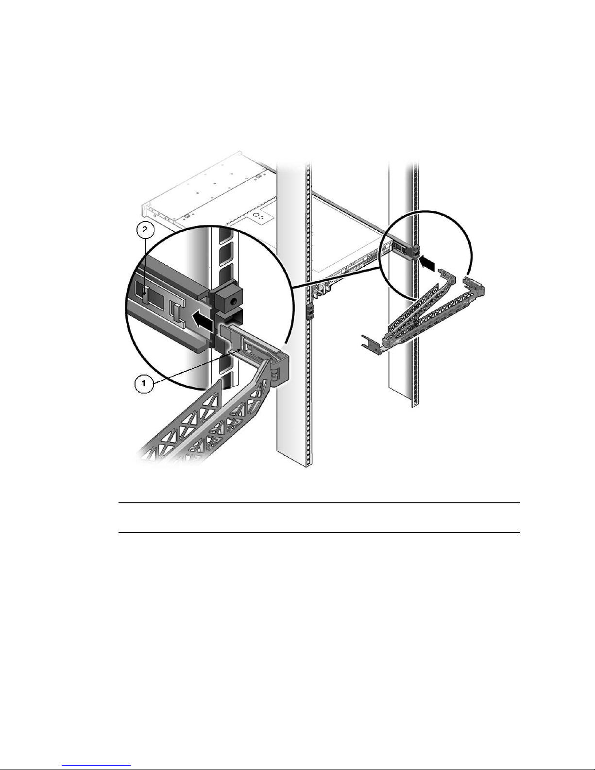
68 Sun Fire X4170, X4270, and X4275 Servers Installation Guide • December 2009
6. Insert the CMA’s mounting bracket connector into the right slide-rail until the
connector locks into place with an audible click (see
FIGURE 3-11).
FIGURE 3-11 Inserting the CMA Mounting Bracket Into the Back of the Right Slide-Rail
Figure Legend
1 CMA mounting bracket
2 Right slide-rail
Page 83
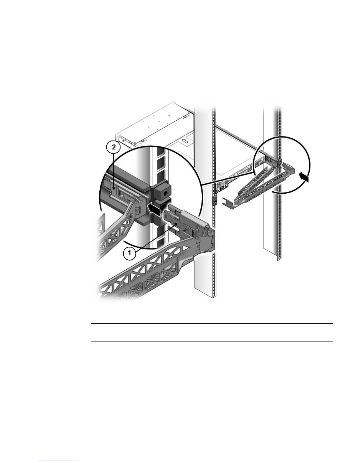
Chapter 3 Installing the Server Into a Rack With Slide-Rails 69
7. Insert the right CMA slide-rail connector into the right slide-rail assembly until
the connector locks into place with an audible click (see
FIGURE 3-12).
FIGURE 3-12 Inserting CMA Slide-Rail Connector Into the Back of the Right Slide-Rail
Assembly
Figure Legend
1 CMA slide-rail connector
2 Right slide-rail assembly
Page 84
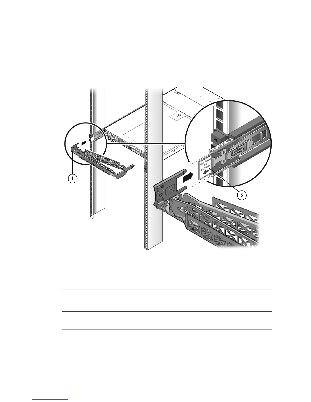
70 Sun Fire X4170, X4270, and X4275 Servers Installation Guide • December 2009
8. Insert the left CMA slide-rail connector into the rail extension on the left sliderail assembly until the connector locks into place with an audible click (see
FIGURE 3-13).
FIGURE 3-13 Connecting the CMA to the Rail Extension Connector
9. Install and route cables to your server, as required.
Note – Instructions for installing the server cables are provided in “Connecting the
Cables” on page 74.
Figure Legend
1 CMA extension arm (on left slide-rail)
2 CMA extension
Page 85
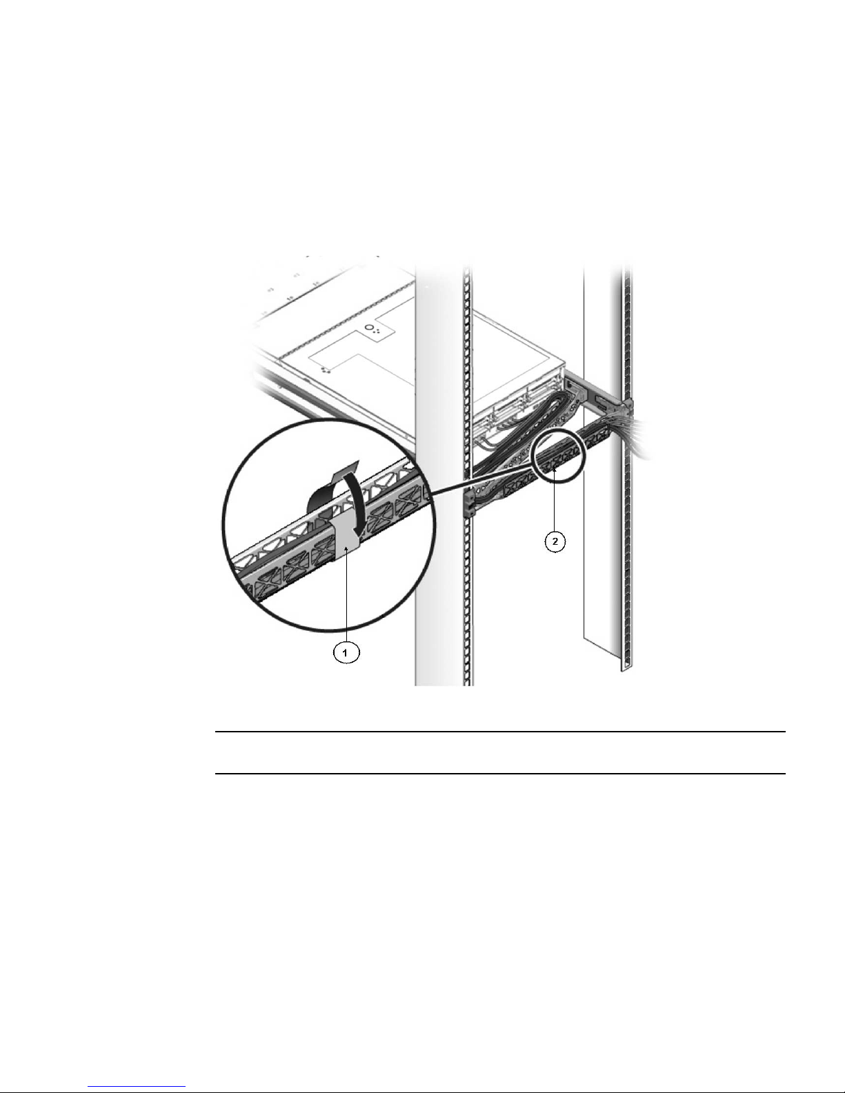
Chapter 3 Installing the Server Into a Rack With Slide-Rails 71
10. Attach the cable hook and loop straps to the CMA, and press them into place to
secure the cables (see
FIGURE 3-14).
For best results, place three cable straps, evenly spaced, on the rear-facing side of
the CMA and three cable straps on the side of the CMA nearest the server.
FIGURE 3-14 Installing CMA Cable Straps
Figure Legend
1 CMA cable strap
2 CMA arm
Page 86

72 Sun Fire X4170, X4270, and X4275 Servers Installation Guide • December 2009
Verifying Operation of the Slide-Rails
and CMA
Use the following procedure to ensure that the slide-rails and CMA are operating
correctly.
▼ Verify Operation of Slide-Rails and CMA
Note – Two people are recommended for this procedure: one to move the server in
and out of the rack, and one to observe the cables and CMA.
1. Slowly pull the server out of the rack until the slide-rails reach their stops.
2. Inspect the attached cables for any binding or kinks.
3. Verify that the CMA extends fully from the slide-rails.
4. Push the server back into the rack, as described in the following sub-steps.
When the server is fully extended, you must release two sets of slide-rail stops to
return the server to the rack:
a. The first set of stops are levers, located on the inside of each slide-rail, just
behind the back panel of the server. These levers are labeled “PUSH.” Push
in both levers simultaneously and slide the server toward the rack.
The server will slide in approximately 18 inches (46 cm) and stop.
Verify that the cables and the CMA retract without binding before you
continue.
b. The second set of stops are the slide-rail release buttons, located near the
front of each mounting bracket (see
FIGURE 3-7). Simultaneously push or pull
both of the slide-rail release buttons, and push the server completely into
the rack until both slide-rail locks engage.
5. Adjust the cable straps and CMA, as required.
Page 87

73
CHAPTER
4
Setting Up the Server
This chapter describes how to connect cables and power on the server for the first
time. It includes the following topics:
■ “Connecting the Cables” on page 74
■ “Connecting to the ILOM Service Processor for the First Time” on page 78
■ “Applying Main Power to the Server for the First Time” on page 84
Page 88
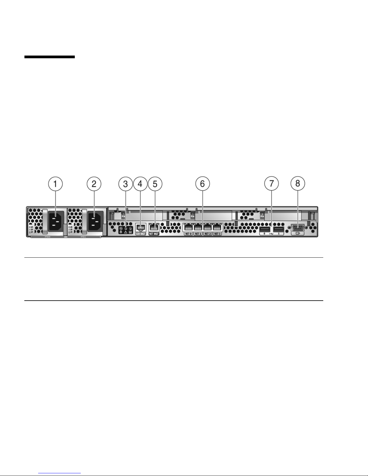
74 Sun Fire X4170, X4270, and X4275 Servers Installation Guide • December 2009
Connecting the Cables
Connect the power and data cables to the server back panel.
Connector Locations
FIGURE 4-1 shows and describes the locations of the Sun Fire X4170 Server back panel
connectors
.
FIGURE 4-1 Sun Fire X4170 Server Back Panel Connectors
Figure Legend
1 Power supply unit 0 connector 5 Service processor (SP) network management (NET
MGT) Ethernet port
2 Power supply unit 1 connector 6 Gigabit Ethernet ports NET-0, 1, 2, 3
3 System status LEDs 7 USB 2.0 ports (0, 1)
4 Serial management (SER MGT)/RJ-45 serial port 8 HD15 video connector (analog VGA)
Page 89
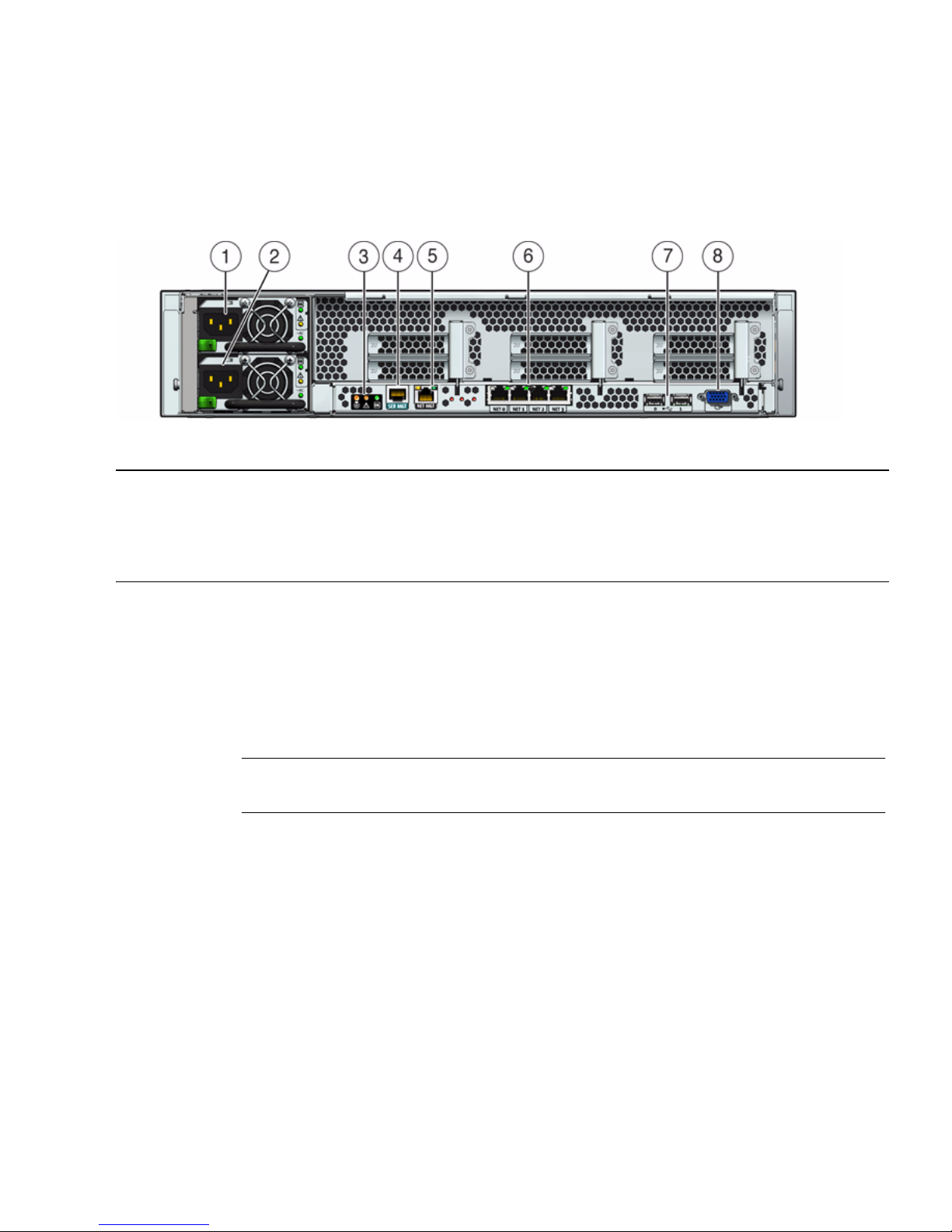
Chapter 4 Setting Up the Server 75
FIGURE 4-2 shows and describes the locations of the Sun Fire X4270 and X4275
Servers back panel connectors
.
FIGURE 4-2 Sun Fire X4270 and X4275 Server Back Panel
▼ Cable the Server
Connect the server power cables and external cables in the following order:
1. Connect two grounded server power cords to grounded electrical outlets.
Note – Connect only one cable if your server does not have a redundant power
supply.
2. Connect the two server power cords to the AC power connectors on the back
panel of the server [1, 2].
In standby power mode, the Power/OK LED on the front panel blinks, indicating
that the service processor (SP) is working as shown in FIGURE 4-3, FIGURE 4-4, and
FIGURE 4-5. At this point, before initial configuration, standby power is supplied only
to the SP and power supply fans.
Figure Legend
1 Power supply unit 1 connector 5 Service processor (SP) network management (NET
MGT) Ethernet port
2 Power supply unit 0 connector 6 Gigabit Ethernet ports NET-0, 1, 2, 3
3 System status LEDs 7 USB 2.0 ports (0, 1)
4 Serial management (SER MGT)/RJ-45 serial port 8 HD15 video connector (analog VGA)
Page 90
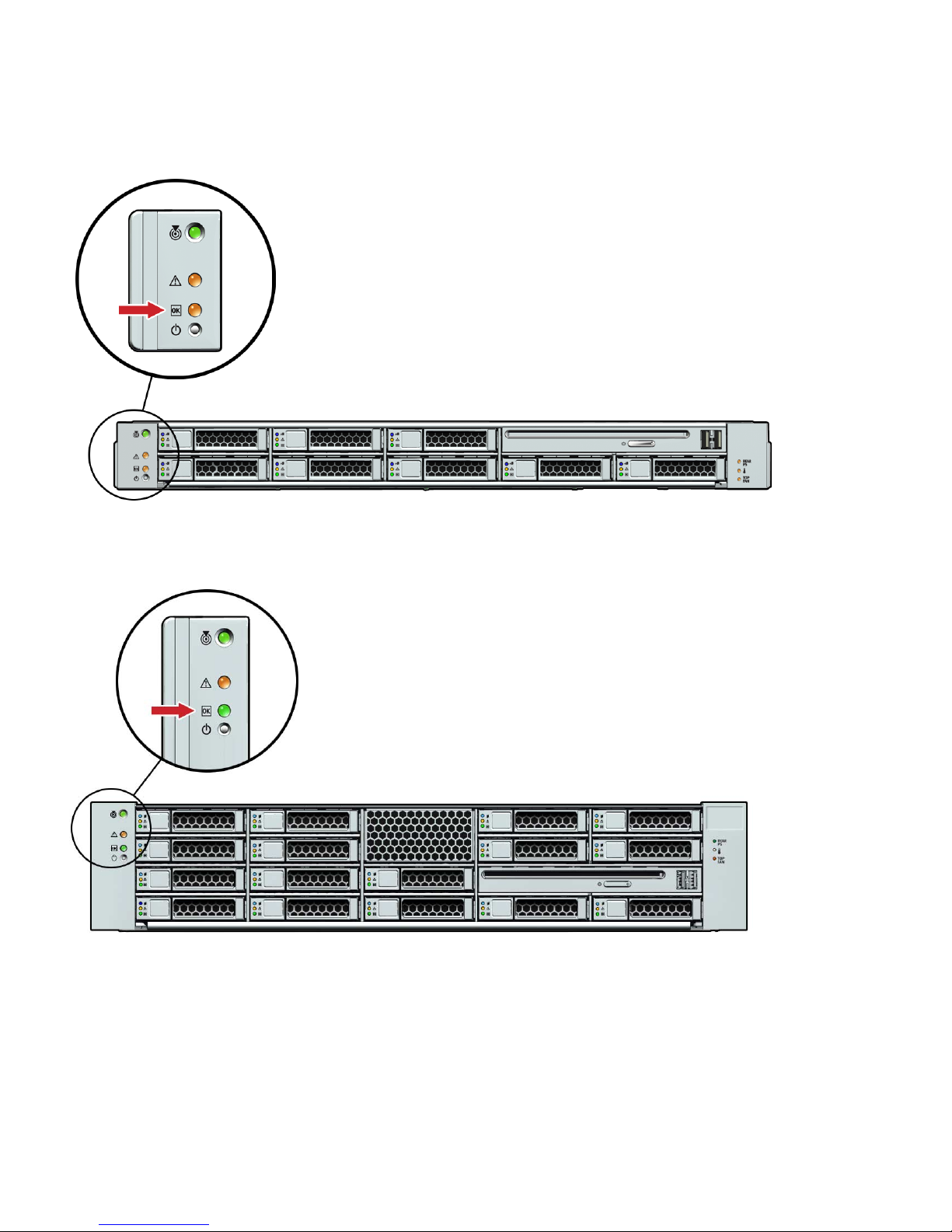
76 Sun Fire X4170, X4270, and X4275 Servers Installation Guide • December 2009
FIGURE 4-3 Sun Fire X4170 Server Front Panel Power/OK LED
FIGURE 4-4 Sun Fire X4270 Server Front Panel Power/OK LED
Page 91
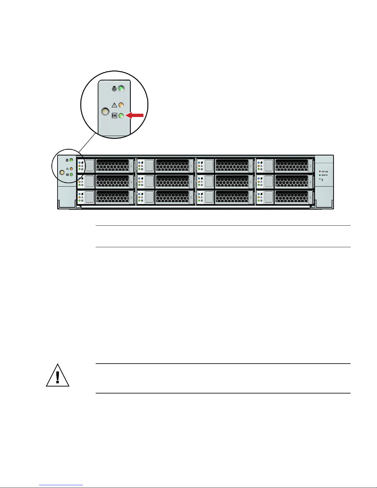
Chapter 4 Setting Up the Server 77
FIGURE 4-5 Sun Fire X4275 Server Front Panel Power/OK LED
Note – Do not push the Power button at this time. Do not apply main power to the rest
of the server until you are ready to install a platform operating system.
3. Connect a serial null modem cable to the SER MGT/RJ-45 serial port [4].
See “Connecting to the ILOM Service Processor for the First Time” on page 78 for
more information about viewing system output from a serial console.
4. Connect Ethernet cables to the SP NET MGT Ethernet port [5].
5. Connect Ethernet cables to the Gigabit Ethernet (NET) connectors as needed for
OS support [6].
6. (Optional) Connect any additional external devices, as required, to the server’s
USB [7] and/or HD15 Video [8] connectors.
7. Connect to the Integrated Lights Out Manager (ILOM) SP. See the next section.
Caution – Do not operate the server without all fans, component heatsinks, air
baffles, and the cover installed. Severe damage to server components can occur if the
server is operated without adequate cooling mechanisms.
Page 92

78 Sun Fire X4170, X4270, and X4275 Servers Installation Guide • December 2009
Connecting to the ILOM Service
Processor for the First Time
This section describes how to connect to the ILOM service processor (SP) for initial
setup and configuration. It covers the following topics:
■ “About ILOM SP IP Addresses” on page 78
■ “About ILOM SP Interfaces” on page 78
■ “Determining the ILOM SP IP Address” on page 79
■ “Changing the ILOM SP IP Address” on page 81
About ILOM SP IP Addresses
The ILOM SP is assigned a DHCP IP address by default. There are two requirements
for DHCP IP address assignment to occur:
■ Connection to your network must be through a NET MGT port.
■ DHCP services must be present on your network infrastructure.
If a DHCP server cannot be reached after three DHCP requests, the ILOM SP is
assigned a static IP address based on the network management port MAC address.
This IP address is always in the format 192.168.xxx.xxx.
About ILOM SP Interfaces
Choose from one of several ILOM SP interfaces to support system management on
your server. You can access SP firmware applications through the following ILOM
SP interfaces:
■ Serial port command-line interface (CLI) (local access)
■ Secure shell (SSH) CLI (remote access over the network)
■ Web browser user interface (BUI) (remote access over the network)
Page 93

Chapter 4 Setting Up the Server 79
Determining the ILOM SP IP Address
You can use either of the following methods to determine the IP address of the
ILOM SP for remote network access:
■ “Use the BIOS Setup Utility to View the Assigned ILOM SP IP Address” on
page 79
■ “Use a Serial Connection to View the Assigned ILOM SP IP Address” on page 80
▼ Use the BIOS Setup Utility to View the Assigned ILOM
SP IP Address
To access the BIOS Setup utility and view the ILOM SP IP address, complete the
following steps:
1. Power on the server (or restart the server if it is running).
2. When the Sun Microsystems splash screen or text prompt appears during the
power-on self-test (POST) operation, press F2 to access the BIOS settings.
3. Using the left and right arrow keys on the keyboard, navigate to the Advanced
tab.
The Advanced screen appears.
4. Using the up and down arrow keys, select the IPMI Configuration option and
press Enter to go to the subscreen.
The IPMI Configuration subscreen appears.
5. Using the up and down arrow keys, select the Set LAN Configuration option
and press Enter.
The LAN Configuration subscreen appears and shows the current ILOM SP IP
address.
6. Record the IP address as you will need it to log in to ILOM using SSH or a web
browser.
Note – If the IP address is in the form of 192.168.xxx.xxx, the DHCP server might
not have assigned an address and the SP might use a static address.
Page 94

80 Sun Fire X4170, X4270, and X4275 Servers Installation Guide • December 2009
▼ Use a Serial Connection to View the Assigned ILOM SP
IP Address
To establish a connection to the SP using a serial connection (SER MGT port),
complete the following steps:
1. Ensure that the server hardware is installed and cables are connected.
Ensure that the power is in standby mode and the green Power/OK LED blinks.
See “Connecting the Cables” on page 74.
2. Verify that your terminal, laptop, PC, or terminal server is operational.
3. Configure the terminal device or the terminal emulation software running on a
laptop or PC to the following settings:
■ 8,N,1: eight data bits, no parity, one stop bit
■ 9600 baud
■ Disable hardware flow control (CTS/RTS)
■ Disable software flow control (XON/XOFF)
4. Connect a null serial modem cable from the SER MGT/RJ-45 serial port on the
server back panel to the terminal device (if not connected already).
See
FIGURE 4-1 and FIGURE 4-2 for the position of the serial port on the back panel.
5. Press Enter on the terminal device to establish a connection between the
terminal device and the ILOM SP.
ILOM displays a login prompt, after a short wait.
login:
Note – If you connect to the serial port on the server before the ILOM SP has been
powered on or during its power-on sequence, SP boot messages might be displayed
prior to the login prompt.
6. Type the default user name, and the default password to log in to the ILOM SP.
Username: root
Password: changeme
ILOM displays a default command prompt (
->), indicating that you have
successfully logged in to ILOM.
Page 95

Chapter 4 Setting Up the Server 81
7. To display the current SP IP address, type:
-> show /SP/network
The IP information appears, as shown in the following sample:
/SP/network
Targets:
commitpending = (Cannot show property)
ipaddress = 129.148.53.128
ipdiscovery = static
ipgateway = 129.148.53.248
ipnetmask = 255.255.255.0
macaddress = 00:1E:68:0F:4A:84
managementport = /SYS/SP/NET0
outofbandmacaddress = 00:14:4F:E7:2E:48
pendingipaddress = 129.148.53.128
pendingipdiscovery = static
pendingipgateway = 129.148.53.248
pendingipnetmask = 255.255.255.0
pendingmanagementport = /SYS/SP/NET0
sidebandmacaddress = 00:14:4F:E7:2E:49
8. Record the IP address as you will need it to log in to ILOM using SSH or an
internet browser.
Changing the ILOM SP IP Address
You can use any of the following methods to change the current IP address of the
ILOM SP:
■ “Use the BIOS Setup Utility to Change the ILOM SP IP Address” on page 82
■ “Use the Serial Connection to Change the ILOM SP IP Address” on page 82
■ “Use a Web Browser to Change the ILOM SP IP Address” on page 83
Page 96

82 Sun Fire X4170, X4270, and X4275 Servers Installation Guide • December 2009
▼ Use the BIOS Setup Utility to Change the ILOM SP IP
Address
To access the BIOS Setup utility and change the ILOM SP IP address, complete the
following steps:
1. Follow Step 1 through Step 5 in the procedure “Use the BIOS Setup Utility to
View the Assigned ILOM SP IP Address” on page 79.
The LAN Configuration subscreen appears and shows the current SP IP address.
2. In the LAN Configuration subscreen, using the up and down arrow keys,
navigate to the IP Assignment field.
The current IP assignment mode is highlighted.
3. If necessary, change the IP Assignment field from DHCP to static.
4. Using the up and down arrow keys, navigate to the IP Address field.
The current IP address is highlighted.
5. Type the new IP address.
Note – If the IP address is in the form of 192.168.xxx.xxx, the DHCP server might
not have assigned an address and the SP might use a static address.
6. Press F10 to save the change and exit the BIOS Setup utility.
▼ Use the Serial Connection to Change the ILOM SP IP
Address
This section provides two examples of using the serial connection to change the
ILOM SP IP address.
Example 1
To change the SP DHCP IP address to a static IP address using the serial connection
(SER MGT port), complete the following steps:
1. Follow Step 1 through Step 6 in the procedure “Use a Serial Connection to View
the Assigned ILOM SP IP Address” on page 80.
2. At the ILOM command prompt, type the following command to determine the
SP IP address:
-> show /SP/network
Page 97

Chapter 4 Setting Up the Server 83
3. To assign a static IP address, type the following commands in the exact order
shown:
-> set /SP/network/ pendingipdiscovery=static
-> set /SP/network/ pendingipaddress=xxx.xxx.xxx.xxx
-> set /SP/network/ pendingipnetmask=xxx.xxx.xxx.xxx
-> set /SP/network/ pendingipgateway=xxx.xxx.xxx.xxx
-> set /SP/network/ commitpending=true
Where xxx are the IP address numbers.
4. Type show /SP/network to view and verify the newly assigned static IP
address settings.
Example 2
To change the SP static IP address to a DHCP IP address using the serial connection
(SER MGT port), complete the following steps:
1. Follow Step 1 through Step 6 in the procedure “Use a Serial Connection to View
the Assigned ILOM SP IP Address” on page 80.
2. At the ILOM command prompt, type the following command to change a static
address to a DHCP address:
-> set /SP/network pendingipdiscovery=dhcp
-> set /SP/network commitpending=true
3. Type show /SP/network to view the newly assigned DHCP IP address.
DHCP enabled is shown as ipdiscovery=dhcp
▼ Use a Web Browser to Change the ILOM SP IP Address
Note – The SP web browser interface can be accessed only if you know the SP IP
address. See “Determining the ILOM SP IP Address” on page 79.
To change a static IP address, using the SP ILOM web browser interface, complete
the following steps:
1. Open a supported web browser, such as Internet Explorer, Mozilla, or Firefox.
2. Type the IP address of the ILOM SP in the browser address bar.
For example: http://xxx.xxx.xxx.xxx
Where xxx.xxx.xxx.xxx is the IP address of the ILOM SP.
Page 98
84 Sun Fire X4170, X4270, and X4275 Servers Installation Guide • December 2009
3. Accept the certificate when prompted.
4. Enter your user name (root) and password (changeme).
5. Select the Configuration tab and then the Network tab.
6. Set configurations, such as IP configuration, as required.
a. Do one of the following:
■ If DHCP is required, select the Enable DHCP check box.
■ If STATIC is required, clear the Enable DHCP check box, and manually set
all IP information.
b. If you manually change the IP address, you must manually change the
subnet mask, because the subnet mask changes according to the IP address
class.
7. Save your settings.
8. Log out of ILOM.
9. If the IP address changes, you must reconnect to ILOM using the newly
assigned IP address, because the current session will become unresponsive.
For detailed information on using ILOM, see the Sun Integrated Lights Out
Manager 2.0 User ’s Guide (820-1188).
Applying Main Power to the Server for
the First Time
When you are ready to install a supported operating system, you can apply main
power to the server.
▼ Apply Main Power to the Server
To turn on main power to the server for the first time, following these steps:
1. Verify that the power cord has been connected and that standby power is on.
In standby power mode, the Power/OK LED on the front panel blinks. See
FIGURE 4-3, FIGURE 4-4,orFIGURE 4-5.
2. Verify that you are connected to the server through the serial management (SER
MGT) port; perform the following sub-steps:
Page 99

Chapter 4 Setting Up the Server 85
a. Ensure that the server hardware is installed and cables are inserted.
b. Verify that your terminal, laptop, PC, or terminal server is operational.
c. Configure the terminal device or the terminal emulation software running on
a laptop or PC to the following settings:
■ 8,N,1: eight data bits, no parity, one stop bit
■ 9600 baud
■ Disable hardware flow control (CTS/RTS)
■ Disable software flow control (XON/XOFF)
d. Connect a null serial modem cable from the server’s back panel SER
MGT/RJ-45 port to the terminal device (if not connected already).
See
FIGURE 4-1 and FIGURE 4-2 for the SER MGT/RJ-45 port location.
e. Press Enter on the terminal device to establish a connection between the
terminal device and the ILOM SP.
ILOM displays a login prompt, after a short wait.
login:
f. Type the default user name, and the default password to log in to the ILOM
SP.
Username: root
Password: changeme
ILOM displays a default command prompt (
-> ), indicating that you have
successfully logged in to ILOM.
3. Use a nonconductive stylus such as a pencil, or other pointed object, to press
and release the recessed Power button on the server front panel.
When main power is applied to the server, the green Power/OK LED next to the
Power button lights and remains lit.
4. To display a screen for installing the preinstalled Solaris or OpenSolaris OS
from the server SER MGT port, type:
-> start /SP/console
5. To install and configure the preinstalled Solaris or OpenSolaris OS software,
proceed to “Configuring the Preinstalled Solaris 10 Operating System” on page 87
or “Configuring the Preinstalled OpenSolaris Operating System” on page 103.
Note – To return to the ILOM command-line interface from the serial console, press
ESC ( , depending on your keyboard (U.S.A. or international).
Page 100

86 Sun Fire X4170, X4270, and X4275 Servers Installation Guide • December 2009
 Loading...