

Sun Microsystems Sun Fire X4100, Sun Fire X4100 M2, Sun Fire X4200, Sun Fire X4200 M2 Service Manual
Page 1

Sun Fire
and X4200/X4200 M2
Servers Service Manual
™
X4100/X4100 M2
Sun Microsystems, Inc.
www.sun.com
Part No. 819-1157-23
August 2009, Revision A
Submit comments about this document by clicking the Feedback[+] link at: http://docs.sun.com
Page 2

Copyright ©2009 Sun Microsystems, Inc., 4150 Network Circle,Santa Clara, California 95054, U.S.A.All rights reserved.
Sun Microsystems, Inc. has intellectual property rights relating to technologyembodied in the product that is described in this document. In
particular,and without limitation, these intellectualproperty rightsmay include one or more ofthe U.S. patents listed at
http://www.sun.com/patents and one or more additional patents or pending patent applications in the U.S. and in other countries.
This distributionmay include materials developed bythird parties.
Parts ofthe product may be derived from BerkeleyBSD systems, licensed from the University ofCalifornia. UNIX is a registered trademark in
the U.S.and in other countries, exclusivelylicensed through X/Open Company, Ltd.
Sun, SunMicrosystems, the Sun logo, Java, Netra, Solaris, Sun Ray, Sun Fire Servers, Sun Fire X4100Server, X4100 M2 Server, X4200Server,
X4200 M2Server, SunVTS, the JavaCoffee Cuplogo, the Solaris logo, Sunand Java are trademarks or registered trademarks of Sun
Microsystems, Inc., or its subsidiaries, in the U.S. and other countries.
UNIX isa registeredtrademark in the United Statesand other countries, exclusively licensed through X/OpenCompany, Ltd.AMD Opteron
TM
AMD, Opteron, the AMD logo, the AMD Opteron logo are trademarks or registered trademarks of Advanced Micro Devices.
The OPENLOOK and Sun™ Graphical UserInterface was developed by SunMicrosystems, Inc. for its users and licensees.Sun acknowledges
the pioneeringefforts of Xerox in researching and developing the concept of visual or graphical user interfaces for the computer industry. Sun
holds anon-exclusive license from Xerox to the Xerox GraphicalUser Interface, which license alsocovers Sun's licensees who implementOPEN
LOOK GUIsand otherwise comply with Sun'swritten license agreements.
Use ofany spare or replacement CPUs is limitedto repair or one-for-one replacement of CPUs in products exportedin compliance with U.S.
export laws.Use of CPUs as product upgradesunless authorized by the U.S.Government is strictly prohibited.
DOCUMENTATION IS PROVIDED "AS IS" AND ALL EXPRESS OR IMPLIED CONDITIONS, REPRESENTATIONS AND WARRANTIES,
INCLUDING ANY IMPLIED WARRANTY OF MERCHANTABILITY, FITNESS FOR APARTICULAR PURPOSEOR NON-INFRINGEMENT,
ARE DISCLAIMED, EXCEPT TO THE EXTENT THAT SUCH DISCLAIMERS ARE HELD TO BE LEGALLY INVALID.
Copyright ©2009 Sun Microsystems, Inc., 4150 Network Circle,Santa Clara, California 95054, Etats-Unis.Tousdroits réservés.
Sun Microsystems, Inc. détient les droits de propriété intellectuels relatifs àla technologie incorporée dans leproduit qui est décrit dans ce
document. Enparticulier, et ce sanslimitation, ces droits de propriété intellectuelle peuvent inclure unou plus des brevets américains listés à
l'adresse http://www.sun.com/patents et unou les brevets supplémentaires ou les applicationsde breveten attente aux Etats -Unis et dans
les autres pays.
Cette distributionpeut inclure des éléments développés par destiers.
Des partiesde ce produit pourront être dérivées des systèmes BerkeleyBSD licenciés par l'Université deCalifornie. UNIX est une marque
déposée auxEtats-Unis et dans d'autres pays et licenciée exclusivement par X/Open Company, Ltd.
Sun, SunMicrosystems, le logo Sun, Java, Netra, Solaris,Sun Ray, Sun Fire Servers, Sun Fire X4100 Server,X4100 M2 Server, X4200 Server,X4200
M2 Server, SunVTS, le logo JavaCoffee Cup, le logo Solaris, Sun et Java sont des marques defabrique ou des marques déposées de Sun
Microsystems, Inc., ou ses filiales, aux Etats-Unis et dans d'autres pays.
UNIX estune marque enregistree aux Etats-Unis et dans d'autres pays et licenciée exclusivement par X/Open Company Ltd. AMD Opteron est
une marque déposée de Advanced Micro Devices, Inc.
L'interface d'utilisationgraphique OPEN LOOK et Sun(TM)a été développée par SunMicrosystems, Inc. pour ses utilisateurs et licenciés.Sun
reconnaît les efforts depionniers de Xerox pour la recherche et le développementdu concept des interfaces d'utilisationvisuelle ou graphique
pour l'industriede l'informatique. Sun détient unelicense non exclusive de Xerox surl'interface d'utilisation graphique Xerox, cette licence
couvrant égalementles licenciés de Sun quimettent en place l'interface d'utilisationgraphique OPEN LOOK et qui,en outre,se conforment aux
licences écritesde Sun.
L'utilisation depieces detachees ou d'unites centralesde remplacement est limitee aux reparations oua l'echange standard d'unites centrales
pour lesproduits exportes, conformement a la legislation americaine en matiere d'exportation. Sauf autorisationpar les autorites des EtatsUnis, l'utilisationd'unites centrales pour proceder a des mises a jour de produits estrigoureusement interdite.
LA DOCUMENTATION EST FOURNIE "ENL'ETAT" ET TOUTES AUTRES CONDITIONS,DECLARATIONS ET GARANTIES EXPRESSES
OU TACITES SONT FORMELLEMENT EXCLUES, DANSLA MESURE AUTORISEE PAR LA LOI APPLICABLE, Y COMPRIS NOTAMMENT
TOUTE GARANTIE IMPLICITE RELATIVE A LA QUALITE MARCHANDE, A L'APTITUDE A UNE UTILISATION PARTICULIERE OU A
L'ABSENCE DECONTREFACON.
Please
Recycle
Page 3

Contents
Preface xi
1. Introduction 1–1
1.1 Features of the Servers 1–1
1.2 Replaceble Components Overview 1–4
1.2.1 Sun Fire X4100/X4100 M2 Server Front Panel 1–4
1.2.2 Sun Fire X4100/X4100 M2 Server Back Panel 1–4
1.2.3 Sun Fire X4100/X4100 M2 Server Components 1–6
1.2.4 Sun Fire X4200/X4200 M2 Server Front Panel 1–8
1.2.5 Sun Fire X4200/X4200 M2 Server Back Panel 1–9
1.2.6 Sun Fire X4200/X4200 M2 Server Components 1–10
1.3 Accessory Kits 1–13
1.4 Additional Options and Replaceable Components 1–14
2. Powering On and Configuring BIOS Settings 2–1
2.1 Powering On the Server 2–2
2.2 Powering Off the Server 2–3
2.3 Configuring BIOS Settings 2–4
2.3.1 Changing the Configuration of a BIOS Menu Item 2–4
2.3.2 PCI Card Slot Boot Priority 2–5
iii
Page 4

2.3.3 Ethernet Port Device and Driver Naming 2–6
2.3.4 Ethernet Port (NIC) Boot Priority 2–7
2.3.5 BIOS Option ROM Size Limitation 2–8
2.3.6 BIOS Setup Screen Overview 2–8
2.3.6.1 BIOS Setup Menu Screens 2–12
2.3.6.2 BIOS Advanced Menu Main Screens 2–13
2.3.6.3 BIOS Advanced Menu CPU Configuration Screen 2–15
2.3.6.4 BIOS Advanced Menu IDE Configuration Screen 2–17
2.3.6.5 BIOS Advanced Menu SuperIO Chipset Configuration
Screen 2–19
2.3.6.6 BIOS Advanced Menu ACPI Settings Screen 2–20
2.3.6.7 BIOS Advanced Menu ACPI Configuration Screen 2–21
2.3.6.8 BIOS Advanced Menu Event Logging Details Screen 2–
22
2.3.6.9 BIOS Advanced Menu HyperTransport Configuration
Screen 2–23
2.3.6.10 BIOS Advanced Menu IPMI Configuration Screen 2–25
2.3.6.11 BIOS Advanced Menu IPMI, View BMC Event Log
Screen 2–26
2.3.6.12 BIOS Advanced Menu IPMI, LAN Configuration
Screen 2–27
2.3.6.13 BIOS Advanced Menu IPMI, PEF Configuration Screen
2–28
2.3.6.14 BIOS Advanced Menu MPS Configuration Screen 2–29
2.3.6.15 BIOS Advanced Menu PCI Express Configuration
Screen 2–30
2.3.6.16 BIOS Advanced Menu, AMD PowerNow
Configuration 2–31
2.3.6.17 BIOS Advanced Menu Remote Access Configuration
Screen 2–32
2.3.6.18 BIOS Advanced Menu USB Configuration Screen 2–33
2.3.6.19 BIOS PCI/PnP Menu 2–35
iv Sun Fire X4100/X4100 M2 and X4200/X4200 M2 Servers Service Manual • August 2009
Page 5

2.3.6.20 BIOS Boot Menu Main Screen 2–37
2.3.6.21 BIOS Boot Settings Configuration Screen 2–38
2.3.6.22 BIOS Boot Menu Boot Device Priority Screen 2–39
2.3.6.23 BIOS Boot Menu Hard Disk Drives Screen 2–41
2.3.6.24 BIOS Boot Menu Removable Drives Screen 2–42
2.3.6.25 BIOS Boot Menu CD/DVD Drives Screen 2–43
2.3.6.26 BIOS Security Settings Menu 2–44
2.3.6.27 BIOS Chipset Menu Main Screen 2–45
2.3.6.28 BIOS Chipset Menu NorthBridge Configuration Screen
2–46
2.3.6.29 BIOS Chipset Menu NorthBridge Memory Configuration
Screen 2–47
2.3.6.30 BIOS Chipset Menu NorthBridge ECC Configuration
Screen 2–48
2.3.6.31 BIOS Chipset Menu SouthBridge Configuration Screen
2–49
2.3.6.32 BIOS Chipset Menu PCI-X Configuration Screen 2–51
2.3.6.33 BIOS Exit Option Menu Screen 2–52
2.4 Resetting SP and BIOS Passwords Using Jumper P4 or J12 2–53
2.4.1 Resetting the SP Password 2–56
2.5 Using the Force-Recovery Jumper P5 or J13 2–57
2.6 Using the Clear CMOS Jumper TP51/TP52 or J9 2–59
2.7 Using the Reset and NMI Switches 2–60
2.8 Updating the BIOS 2–61
2.9 Power-On Self-Test (POST) 2–61
3. Maintaining the Sun Fire Servers 3–1
3.1 Tools and Supplies Needed 3–2
3.2 Locations of Replaceable Components 3–2
3.3 Servicetool FRU Update Procedure 3–2
Contents v
Page 6

3.4 Powering Off the Server 3–4
3.5 Removing the Main Cover of the Sun Fire X4100/X4100 M2 Server 3–6
3.6 Removing the Front Bezel of the Sun Fire X4100/X4100 M2 Server 3–7
3.7 Removing the Front Cover of the Sun Fire X4100/X4100 M2 Server 3–8
3.8 Removing the Main Cover of the Sun Fire X4200/X4200 M2 Servers 3–10
3.9 Removing the Front Bezel of the Sun Fire X4200/X4200 M2 Servers 3–11
3.10 Removing the Front Cover of the Sun Fire X4200/X4200 M2 Servers 3–12
3.11 HT Jumper Configuration for Single-CPU Servers (Sun Fire X4100 M2 and
X4200 M2) 3–13
3.12 Replaceable Component Procedures 3–14
3.12.1 Replacing the Battery 3–15
3.12.2 Replacing a CPU and Heatsink (Sun Fire X4100 and X4200 Servers)
3–17
3.12.3 Replacing a CPU and Heatsink (Sun Fire X4100 M2/X4200 M2
Servers) 3–23
3.12.4 Replacing the DVD-ROM Drive 3–30
3.12.5 Installing a DVD-ROM Drive Upgrade Kit 3–33
3.12.6 Replacing a Fan Module 3–38
3.12.7 Replacing a Fan Connector Board 3–41
3.12.8 Replacing the Front Panel Indicator Board 3–44
3.12.9 Replacing the Front I/O Board 3–46
3.12.10 Replacing the Graphics Redirect and Service Processor (GRASP)
Board 3–51
3.12.11 Servicetool FRU Update Procedure 3–53
3.12.12 Replacing a Drive 3–54
3.12.13 Replacing the Drives Backplane 3–57
3.12.14 DIMM Population Rules 3–61
3.12.14.1 Supported DIMM Configurations 3–63
3.12.14.2 Installing DIMMs Into a Single-CPU System 3–64
3.12.15 Replacing DIMMs 3–65
vi Sun Fire X4100/X4100 M2 and X4200/X4200 M2 Servers Service Manual • August 2009
Page 7

3.12.15.1 Supported DIMMs 3–65
3.12.16 Replacing PCI Cards 3–72
3.12.17 Replacing the Motherboard 3–77
3.12.17.1 Installing the Motherboard 3–82
3.12.18 Replacing a Power Supply 3–83
3.12.19 Replacing the Power Distribution Board (PDB) 3–86
3.12.19.1 Installing the New Power Distribution Board 3–89
3.12.20 Replacing the Rear Fan Tray (Sun Fire X4200/X4200 M2 Servers)
3–89
A. System Specifications A–1
A.1 Sun Fire X4100/X4100 M2 Specifications A–1
A.2 Sun Fire X4200/X4200 M2 Specifications A–3
B. BIOS POST Codes B–1
B.1 How BIOS POST Memory Testing Works B–1
B.2 Redirecting Console Output B–2
B.3 Changing POST Options B–3
B.4 POST Codes B–4
B.5 POST Code Checkpoints B–6
C. Status Indicator LEDs C–1
C.1 External Status Indicator LEDs C–1
C.2 Internal Status Indicator LEDs C–6
D. Sensors D–1
D.1 Sensor Values D–1
D.2 Physical Locations of Sensors D–2
E. Connector Pinouts E–1
E.1 USB Connector E–1
Contents vii
Page 8

E.2 Serial Connector E–2
E.3 10/100BASE-T Connector E–2
E.4 10/100/1000BASE-T Connector E–3
E.5 VGA Video Connector E–4
E.6 Serial Attached SCSI Connector E–5
E.7 Flex Cable Motherboard Connector E–7
E.8 Flex Cable Power Distribution Board Connector E–11
E.9 Flex Cable DVD-ROM Drive Connector E–12
E.10 Motherboard Bus Bar Power Connector E–14
E.11 Front I/O Interconnect Cable Connector E–15
E.12 Power Supply Connector E–17
E.13 Fan Module Connector E–18
F. Serial Attached SCSI BIOS Configuration Utility F–1
F.1 Fusion-MPT SAS BIOS Overview F–1
F.1.1 Boot Initialization With BIOS Boot Specification (BBS) F–2
F.2 Starting the SAS BIOS Configuration Utility F–2
F.3 Configuration Utility Screens F–3
F.3.1 User Input Keys F–4
F.3.2 Adapter List Screen F–4
F.3.3 Global Properties Screen F–6
F.3.4 Adapter Properties Screen F–7
F.3.5 SAS Topology Screens F–10
F.3.6 Device Properties Screen F–14
F.3.7 Device Verify Screen F–15
F.3.8 Advanced Adapter Properties Screen F–17
F.3.9 Advanced Device Properties Screen F–19
F.3.10 PHY Properties Screen F–20
F.3.11 Integrated RAID Configuration and Management Screens F–22
viii Sun Fire X4100/X4100 M2 and X4200/X4200 M2 Servers Service Manual • August 2009
Page 9

F.3.11.1 Select New Array Type Screen F–23
F.3.11.2 Create New Array Screen F–23
F.3.11.3 View Array Screen F–26
F.3.11.4 Manage Array Screen F–29
F.3.11.5 Exit Screen F–31
F.4 Performing RAID Configuration Tasks F–32
F.4.1 RAID Implementation and Support F–33
F.4.1.1 Automatic Data Resynchronization and Hotspares F–
33
F.4.1.2 RAID Level Support F–34
F.4.1.3 RAID Volume Support F–34
F.4.1.4 RAID Combination Support F–34
F.4.2 Creating a RAID 0 Volume F–35
F.4.3 Creating a RAID 1 Volume F–36
F.4.4 Managing Hot Spares F–37
F.4.5 Creating a Second RAID Volume F–38
F.4.6 Viewing RAID Volume Properties F–38
F.4.7 Synchronizing an Array F–38
F.4.8 Activating an Array F–39
F.4.9 Deleting an Array F–39
F.4.10 Locating a Disk Drive F–40
G. Device Paths G–1
G.1 Sun Fire X4100/X4100 M2 Device Paths G–1
G.2 Sun Fire X4200/X4200 M2 Device Paths G–2
Index Index–1
Contents ix
Page 10

x Sun Fire X4100/X4100 M2 and X4200/X4200 M2 Servers Service Manual • August 2009
Page 11

Preface
This document contains information and procedures for maintaining and upgrading
the servers.
Before You Read This Document
It is important that you review the safety guidelines in the Sun Fire X4100/X4100 M2
and X4200/X4200 M2 Servers Safety and Compliance Guide (819-1161).
Product Updates
For product updates that you can download for the Sun Fire X4100 or Sun Fire X4200
servers, go to
http://www.sun.com/servers/entry/x4100/downloads.jsp
This site contains updates for firmware and drivers, as well as CD-ROM .iso
images.
xi
Page 12

Related Documentation
For a description of the document set, see the Where To Find Documentation sheet that
is packed with your system and available at the product's documentation site. Refer
to the following URL, then navigate to your product:
http://www.sun.com/products-nsolutions/hardware/docs/Servers/x64_servers/index.html
This site also contains translated versions of some of these documents in French,
Simplified Chinese, Traditional Chinese, Korean, and Japanese. English
documentation is revised more frequently and might be more up-to-date than the
translated documentation.
For all Sun documentation, refer to:
http://www.sun.com/documentation
For Solaris and other software documentation, refer to:
http://docs.sun.com
Documentation, Support, and Training
The Sun web site provides information about the following additional resources:
Sun Function URL
Support http://www.sun.com/support/index.jsp
Training http://www.sun.com/training
Warranty http://www.sun.com/service/support/warranty/index.html
xii Sun Fire X4100/X4100 M2 and X4200/X4200 M2 Servers Service Manual • August 2009
Page 13

Sun Welcomes Your Comments
Sun is interested in improving its documentation and welcomes your comments and
suggestions. You can submit your comments by going to:
http://www.sun.com/hwdocs/feedback
Please include the title and part number of your document with your feedback:
Sun Fire X4100/X4100 M2 and X4200/X4200 M2 Servers Service Manual, 819-1157-23
Preface xiii
Page 14

xiv Sun Fire X4100/X4100 M2 and X4200/X4200 M2 Servers Service Manual • August 2009
Page 15

CHAPTER
1
Introduction
This chapter describes the features, main components, and accessories of the Sun
Fire™ X4100/X4100 M2 and X4200/X4200 M2 servers.
Note – The information in this chapter applies to all Sun Fire X4100/X4100 M2 and
X4200/X4200 M2 servers, unless otherwise noted.
This chapter contains the following sections:
■ “Features of the Servers” on page 1
■ “Replaceble Components Overview” on page 4
■ “Accessory Kits” on page 13
■ “Additional Options and Replaceable Components” on page 14
1.1 Features of the Servers
These servers take full advantage of the exceptional power and performance of the
AMD Opteron processor. They include an extensive set of reliability, availability, and
serviceability (RAS) features. The servers also provide a remote, integrated lights-out
management (ILOM) service processor (SP) function, including remote boot and
remote software upgrades.
1-1
Page 16

TABLE 1-1 summarizes and compares the features of the servers.
TABLE 1-1 Server Features
Feature or
Component Sun Fire X4100/X4100 M2 Servers Sun Fire X4200/X4200 M2 Servers
CPU
Sun Fire X4100:
Up to two AMD64 Opteron 200 Series
single- or dual-core processors (1-MB L2
cache per core)
Sun Fire X4100 M2:
Up to two AMD64 Opteron 2200 Series
single- or dual-core processors (1-MB L2
cache per core)
Memory
Sun Fire X4100:
Up to eight DIMMs (up to 32GB capacity)
Qualified DIMMs:
• 400-MHz Registered ECC DDR1 DIMMs
Sun Fire X4100 M2:
Up to eight DIMMs (up to 32GB capacity)
Qualified DIMMs:
• 667-MHz Registered ECC DDR2 DIMMs
Disk drives Two Serial Attached SCSI (SAS) disk drives
(2.5 inch or 63.5 mm); up to four disk drives
as a factory-configured option
Board
Motorola MPC8248 @ 266MHz Motorola MPC8248 @ 266MHz
management
controller (BMC)
Sun Fire X4200:
Up to two AMD64 Opteron 200 Series
single- or dual-core processors (1-MB L2
cache per core)
Sun Fire X4200 M2:
Up to two AMD64 Opteron 2200 Series
single- or dual-core processors (1-MB L2
cache per core)
Sun Fire X4200:
Up to eight DIMMs (up to 32GB capacity)
Qualified DIMMs:
• 400-MHz Registered ECC DDR1 DIMMs
Sun Fire X4200 M2:
Up to eight DIMMs (up to 32GB capacity)
Qualified DIMMs:
• 667-MHz Registered ECC DDR2 DIMMs
Four Serial Attached SCSI (SAS) drives
(2.5 inch or 63.5 mm)
RAID options Four-channel SAS RAID disk controller Four-channel SAS RAID disk controller
Network I/O • Four 10/100/1000 BASE-T Gigabit
Ethernet ports (RJ-45 connectors)
• One 10/100 BASE-T Ethernet
management port (RJ-45 Connector)
• One RS-232 serial port (RJ-45 Connector)
PCI I/O
Sun Fire X4100:
• One 133-MHz, low-profile PCIX slot
• One 100-MHz, low-profile PCIX slot
• Right-angle PCI risers
Sun Fire X4100 M2:
• Two 8-lane, low-profile PCIE slots
• Right angle PCIE risers are provided
1-2 Sun Fire X4100/X4100 M2 and X4200/X4200 M2 Servers Service Manual • August 2009
• Four 10/100/1000 BASE-T Gigabit
Ethernet ports (RJ-45 connectors)
• One 10/100 BASE-T Ethernet
management port (RJ-45 Connector)
• One RS-232 serial port (RJ-45 Connector)
Sun Fire X4200:
• One 133-MHz PCIX slot
• One 100-MHz PCIX slot
• Three 66-MHz PCIX slots
Sun Fire X4200 M2:
• Four 8-lane PCIE slots
• One 133-MHz PCIX slot
Page 17

TABLE 1-1 Server Features (Continued)
Feature or
Component Sun Fire X4100/X4100 M2 Servers Sun Fire X4200/X4200 M2 Servers
Other I/O
Removable media
devices
Sun Fire X4100:
• Three USB 1.1 ports
• One VGA video port
Sun Fire X4100 M2:
• Three USB 2.0 capable ports
• One VGA video port
Sun Fire X4100:
Internal slim DVD-ROM drive (not available
Sun Fire X4200:
• Four USB 1.1 ports
• One VGA video port
Sun Fire X4200 M2:
• Four USB 2.0 capable ports
• One VGA video port
Sun Fire X4200:
Internal slim DVD ROM drive
if 4-drives option is ordered)
Sun Fire X4100 M2:
Internal slim DVD ROM with CD-RW (not
Sun Fire X4200 M2:
Internal slim DVD ROM with CD-RW
available if 4-drives option is ordered)
Power Two 550W power supplies Two 550W power supplies
Fans Six front fan modules, each containing two
40mm fans; also one fan in each power
supply
Six front fan modules, each containing a
single 80mm fan; one rear fan tray; also one
fan in each power supply
Chapter 1 Introduction 1-3
Page 18
1.2 Replaceble Components Overview
This section contains illustrations that you can use to become familiar with the
components of the Sun Fire X4100/X4100 M2 servers.
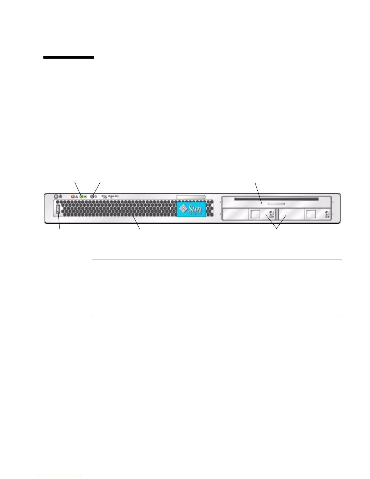
1.2.1 Sun Fire X4100/X4100 M2 Server Front Panel
FIGURE 1-1 shows the features of the front panel.
FIGURE 1-1 Sun Fire X4100/X4100 M2 Server Front Panel
21
4 6
Figure Legend
1 Power/OK LED
2 Power button
3 DVD-ROM drive
4 USB port
5 Serial number sticker on bezel
6 Hard disk drives (2)
5
3
1.2.2 Sun Fire X4100/X4100 M2 Server Back Panel
FIGURE 1-2 shows the features of the back panel.
1-4 Sun Fire X4100/X4100 M2 and X4200/X4200 M2 Servers Service Manual • August 2009
Page 19
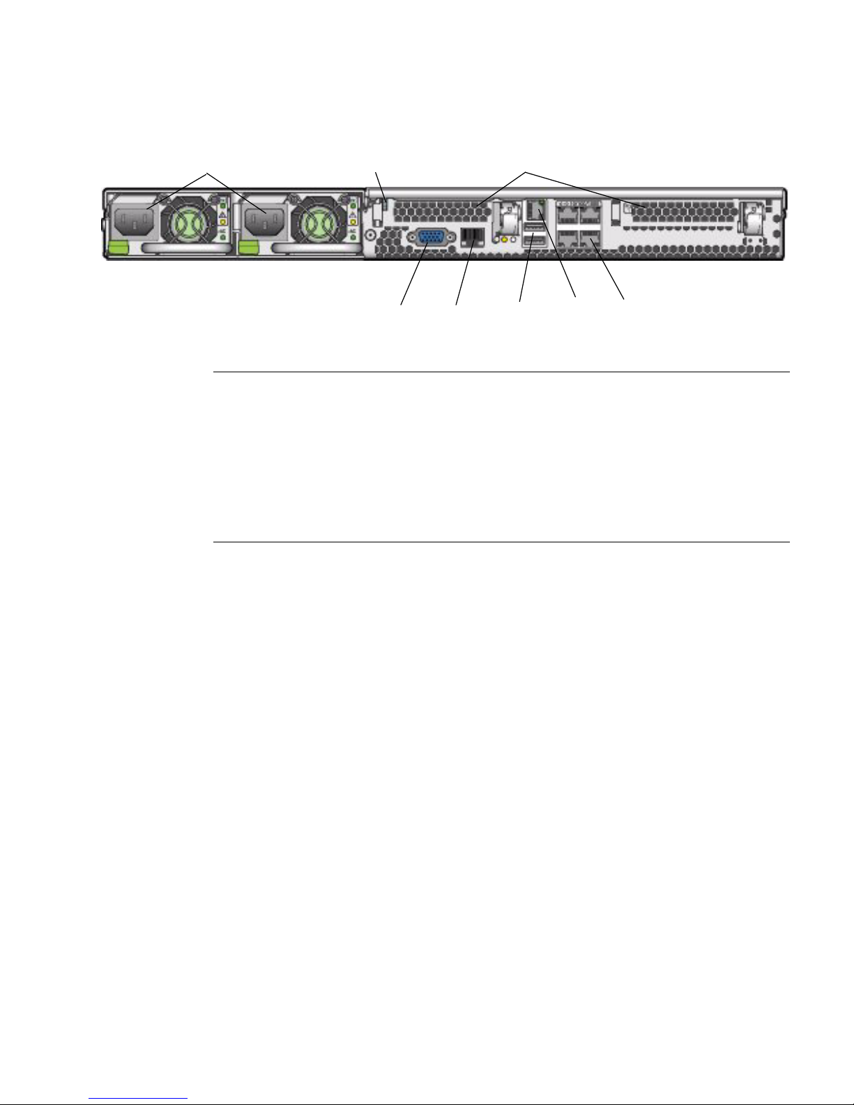
FIGURE 1-2 Sun Fire X4100/X4100 M2 Server Back Panel
1
Figure Legend
1 Power supplies
2 Grounding post
3 PCI card slots (2)
4 Video connector
5 Serial management port
6 USB connectors (2)
7 10/100 Ethernet port for net management
8 10/100/1000 gigabit Ethernet ports (4)
2
3
64 5 87
Chapter 1 Introduction 1-5
Page 20
1.2.3 Sun Fire X4100/X4100 M2 Server Components
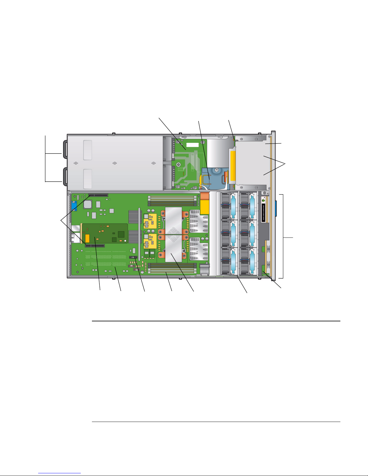
FIGURE 1-3 shows the locations of the Sun Fire X4100 server replaceable components,
with the top covers removed.
FIGURE 1-3 Sun Fire X4100 Replaceable Component Locations
23
4
1
5
6
9
7
8
10
Figure Legend
1 Power supplies (2)
2 Power distribution board
3 Flex cable (underneath cable retainer)
4 Hard disk drive backplane
5 DVD-ROM drive
6 Hard drives (2) (4-drives option available with no DVD-ROM)
7 Fan modules (6)
8 Fan connector boards (2) (not visible—underneath fan modules)
9 PCI-e card slot (2)
10 Graphics-redirect and service processor (GRASP) board
11 Motherboard
1-6 Sun Fire X4100/X4100 M2 and X4200/X4200 M2 Servers Service Manual • August 2009
12 14
1311
15
16
Page 21
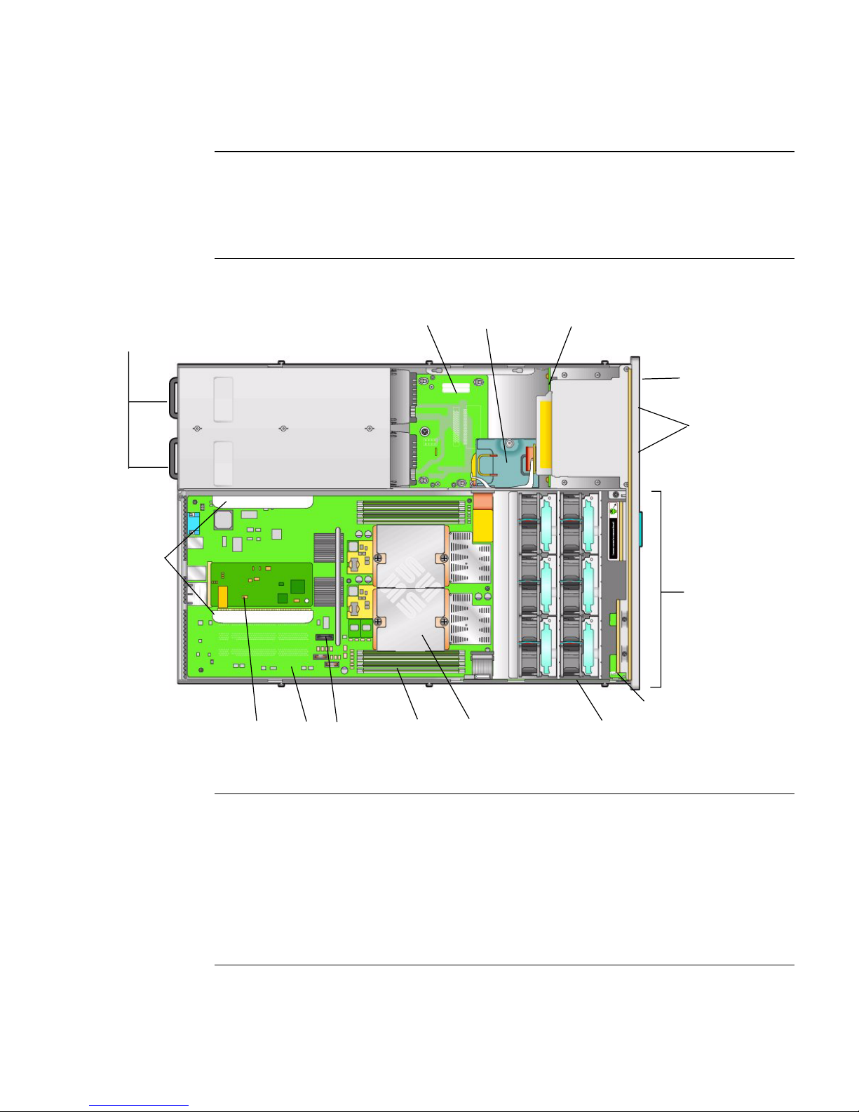
Figure Legend
12 Battery
13 DIMMs (up to 4 for each CPU)
14 CPUs and heatsinks (2)
15 Front I/O board
16 Front panel indicator board
FIGURE 1-4 Sun Fire X4100 M2 Replaceable Component Locations
23
4
1
5
6
9
7
8
16
10
11
12
13
14
15
Figure Legend
1 Power supplies (2)
2 Power distribution board
3 Flex cable (underneath cable retainer)
4 Hard disk drive backplane
5 DVD-ROM drive
6 Hard drives (2), 4-drives option available with no DVD-ROM
7 Fan modules (6)
8 Fan connector boards (2) (not visible—underneath fan modules)
Chapter 1 Introduction 1-7
Page 22
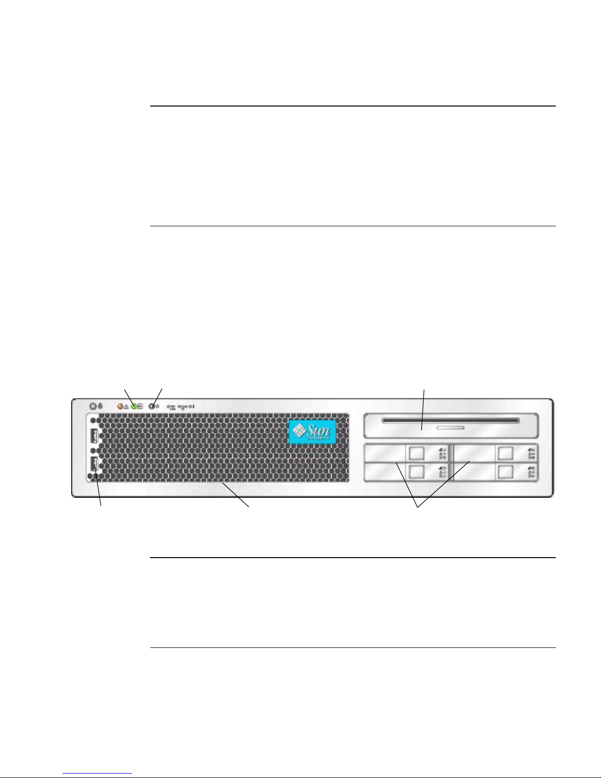
Figure Legend
9 PCI-X card slot (2)
10 Graphics-redirect and service processor (GRASP) board
11 Motherboard
12 Battery
13 DIMMs (up to 4 for each CPU)
14 CPUs and heatsinks (2)
15 Front I/O board
16 Front panel indicator board
FIGURE 1-4 shows the locations of the Sun Fire X4100 M2 server replaceable
components, with the top covers removed.
1.2.4 Sun Fire X4200/X4200 M2 Server Front Panel
FIGURE 1-5 shows the features of the front panel.
FIGURE 1-5 Sun Fire X4200/X4200 M2 Server Front Panel
1
4
2
5
Figure Legend
1 Power/OK LED
2 Power button
3 DVD-ROM drive
4 USB ports (2)
5 Serial number sticker on bezel
6 Hard disk drives (4)
3
6
1-8 Sun Fire X4100/X4100 M2 and X4200/X4200 M2 Servers Service Manual • August 2009
Page 23
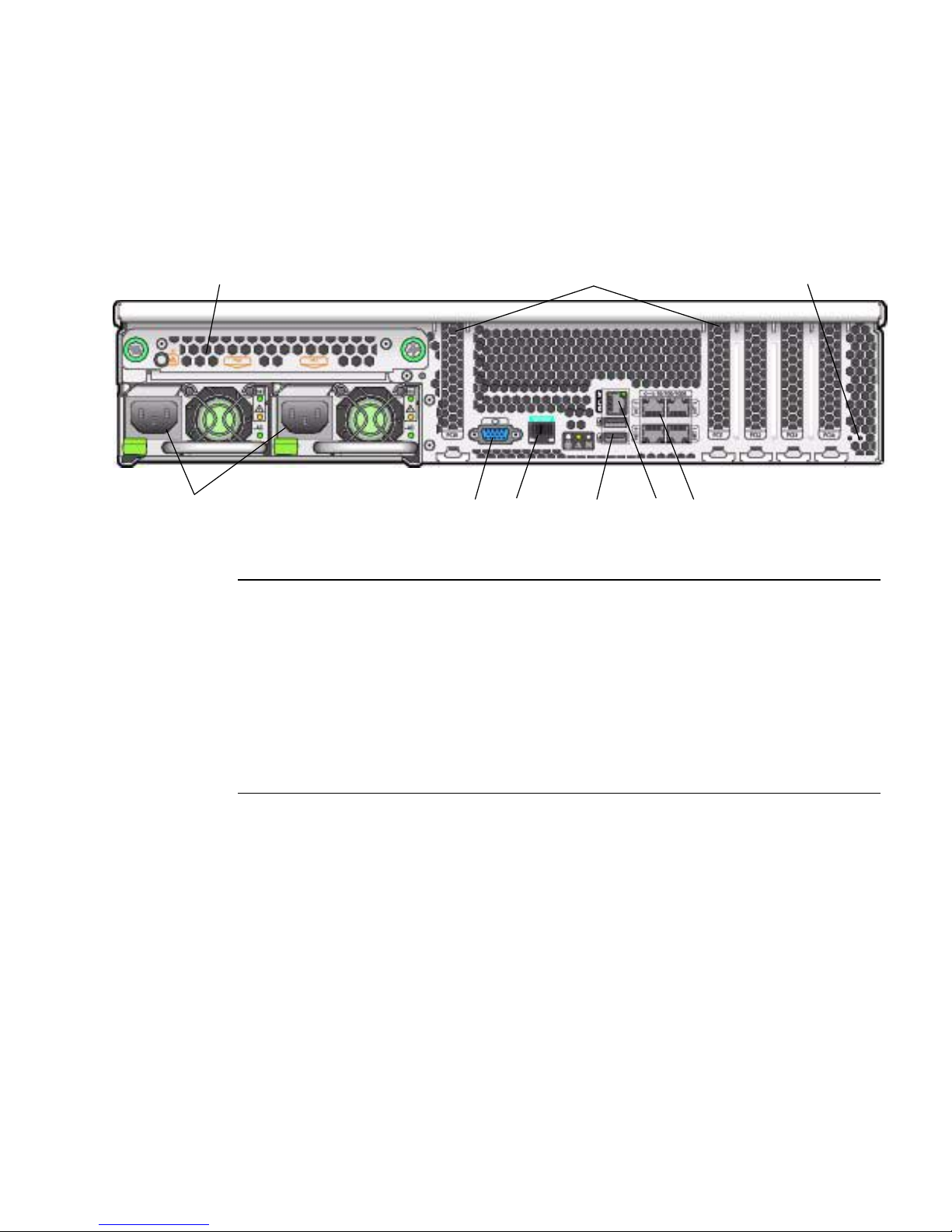
1.2.5 Sun Fire X4200/X4200 M2 Server Back Panel
FIGURE 1-6 shows the features of the back panel.
FIGURE 1-6 Sun Fire X4200/X4200 M2 Server Back Panel
21
4
Figure Legend
1 Rear fan tray
2 PCI card slots (5)
3 Grounding post
4 Power supplies (2)
5 Video connector
6 Serial management port
7 USB connectors (2)
8 10/100/1000 gigabit Ethernet ports (4)
9 10/100 Ethernet port for net management
98675
3
Chapter 1 Introduction 1-9
Page 24
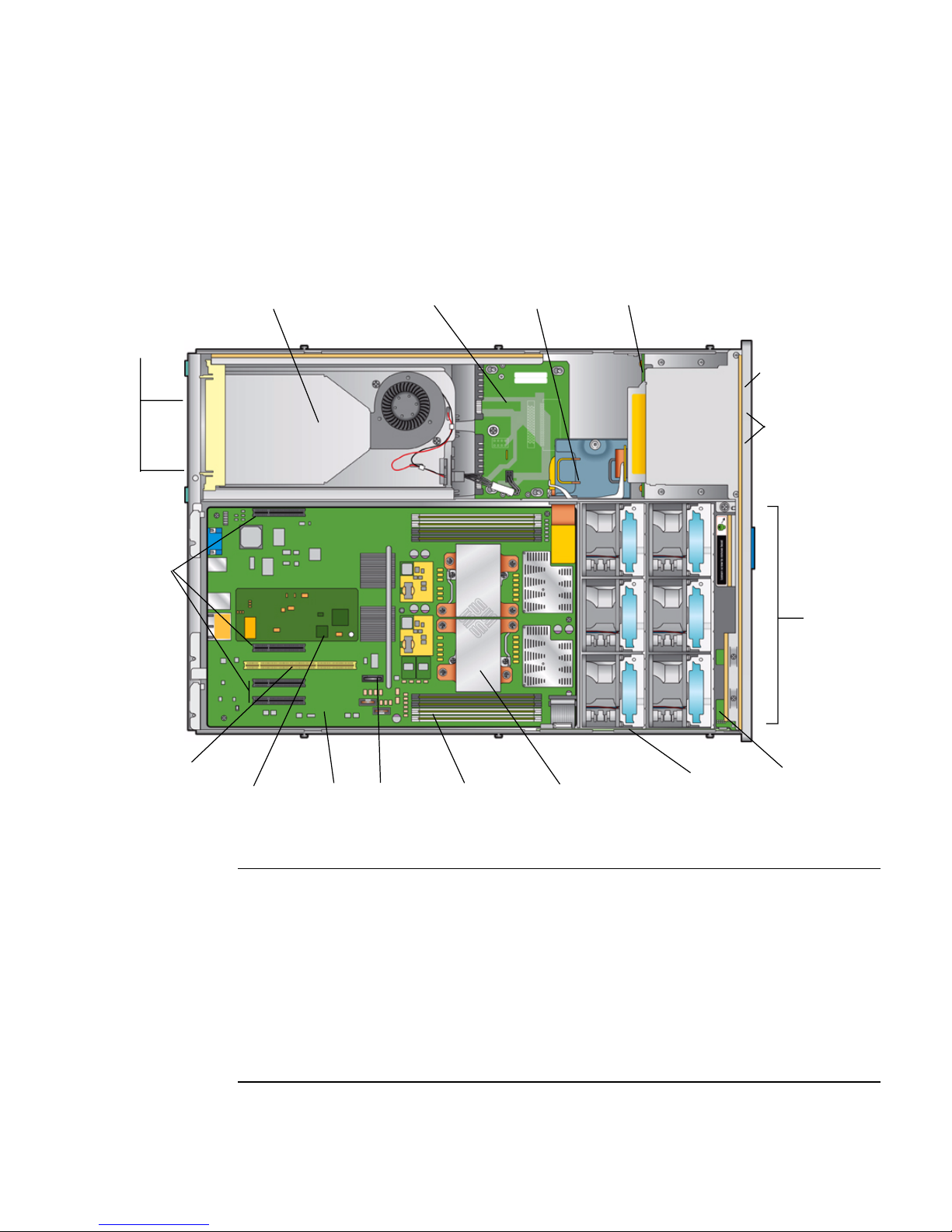
1.2.6 Sun Fire X4200/X4200 M2 Server Components
FIGURE 1-7 shows the locations of the Sun Fire X4200 server replaceable components,
with the top covers removed.
FIGURE 1-7 Sun Fire X4200 Replaceable Component Locations
1
34
5
2
7
8
6
9
10
11
12
Figure Legend
1 Rear fan tray
2 Power supplies (2)
3 Power distribution board
4 Flex cable (underneath cable retainer)
5 Hard disk drive backplane
6 PCIe card slots (4)
7 DVD-ROM drive
8 Hard drives (4)
9 Fan modules (6)
1-10 Sun Fire X4100/X4100 M2 and X4200/X4200 M2 Servers Service Manual • August 2009
14
1513
16
17
18
Page 25
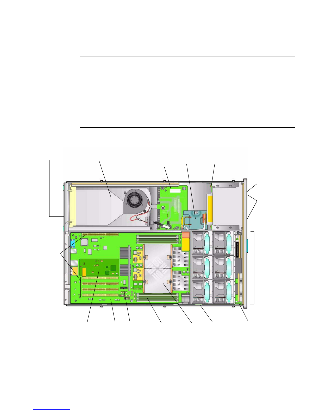
Figure Legend
10 Fan connector boards (2) (not visible—underneath fan modules)
11 PCI-X card slot (1)
12 Graphics-redirect and service processor (GRASP) board
13 Motherboard
14 Battery
15 DIMMs (up to 4 for each CPU)
16 CPUs and heatsinks (2)
17 Front I/O board
18 Front panel indicator board
FIGURE 1-8 Sun Fire X4200 M2 Replaceable Component Locations
2
1
3
4
5
7
8
11
9
10
14
1513
16
17 1812
Chapter 1 Introduction 1-11
Page 26

Figure Legend
1 Rear fan tray
2 Power supplies (2)
3 Power distribution board
4 Flex cable (underneath cable retainer)
5 Hard disk drive backplane
6 PCIe card slots (4)
7 DVD-ROM drive
8 Hard drives (4)
9 Fan modules (6)
10 Fan connector boards (2) (not visible—underneath fan modules)
11 PCI-X card slot (1)
12 Graphics-redirect and service processor (GRASP) board
13 Motherboard
14 Battery
15 DIMMs (up to 4 for each CPU)
16 CPUs and heatsinks (2)
17 Front I/O board
18 Front panel indicator board
FIGURE 1-8 shows the locations of the Sun Fire X4200 M2 server replaceable
components, with the top covers removed.
1-12 Sun Fire X4100/X4100 M2 and X4200/X4200 M2 Servers Service Manual • August 2009
Page 27

1.3 Accessory Kits
TABLE 1-2 lists the contents of the accessory kit that is shipped with the servers.
TABLE 1-2 Accessory Kit
Item Part Number
Sun Fire X4100/X4200 Servers Resource CD
Sun Fire X4100 M2/X4200 M2 Servers Tools and Drivers CD
Sun Fire X4100/X4200 Servers Bootable Diagnostics CD 705-7852
Sun Fire X4100/X4200 Servers Sun Installation Assistant CD 705-7918
Sun N1 System Manager DVD (depending on availability) 825-6459
Sun Fire X4100/X4200 Servers Installation Guide
(printed manual)
Where to Find Sun Fire X4100/X4200 Servers Documentation (printed
sheet)
Serial-to-RJ45 cable adapter (DB9S-to-RJ-45F) 530-3100
705-7917
819-1155
819-3119
Chapter 1 Introduction 1-13
Page 28

1.4 Additional Options and Replaceable
Components
Supported components and their part numbers are subject to change over time. For
the most updated list of replaceable components for these servers, refer to the
following URL:
http://sunsolve.sun.com/handbook_pub/Systems
1. Click the name and model of your server.
2. On the product page that opens for the server, click Full Components List to
view the list of components.
Note – These servers are fully compliant with the Reduction of Hazardous
Substances (RoHS) Directive.
Caution – Some AMD CPUs are released as special editions, which might differ in
wattage from other CPUs. Do not mix the two different types of CPUs. Always make
sure that all CPUs in the server have the same part number.
1-14 Sun Fire X4100/X4100 M2 and X4200/X4200 M2 Servers Service Manual • August 2009
Page 29

CHAPTER
2
Powering On and Configuring BIOS
Settings
This chapter contains the following procedures and information:
■ Section 2.1, “Powering On the Server” on page 2-2
■ Section 2.2, “Powering Off the Server” on page 2-3
■ Section 2.3, “Configuring BIOS Settings” on page 2-4
■ Section 2.4, “Resetting SP and BIOS Passwords Using Jumper P4 or J12” on
page 2-53
■ Section 2.5, “Using the Force-Recovery Jumper P5 or J13” on page 2-57
■ Section 2.6, “Using the Clear CMOS Jumper TP51/TP52 or J9” on page 2-59
■ Section 2.7, “Using the Reset and NMI Switches” on page 2-60
■ Section 2.8, “Updating the BIOS” on page 2-61
■ Section 2.9, “Power-On Self-Test (POST)” on page 2-61
Note – The information in this chapter applies to all Sun Fire X4100/X4100 M2 and
X4200/X4200 M2 servers, unless otherwise noted.
2-1
Page 30
2.1 Powering On the Server
Note – Before powering on your server for the first time, follow the installation and
cabling instructions provided in the Sun Fire X4100/X4200 Servers Installation Guide,
which is shipped with the system and is also available online at:
http://www.sun.com/documentation
Caution – Do not operate the server without all fans, component heatsinks, air
baffles, and covers installed. Severe damage to server components can occur if the
server is operated without adequate cooling mechanisms.
1. Verify that power cords have been connected to the server's power supplies and
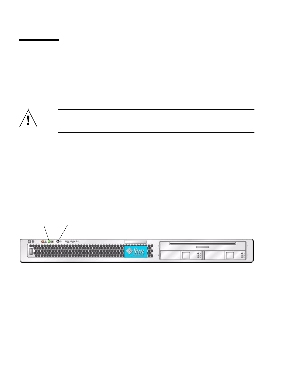
that standby power is on.
In standby power mode, the Power/OK LED on the front panel flashes,
indicating that the service processor is working and the system is ready to be
fully powered on to main power mode. See
location.
2. Use a nonconducting pointer or stylus to press and release the recessed Power
button on the server front panel which is shown in
FIGURE 2-1 orFIGURE 2-2 for the LED
FIGURE 2-1 or FIGURE 2-2.
FIGURE 2-1 When main power is applied to the full server, the Power/OK LED next to the Power
button lights and remains lit.
21
2-2 Sun Fire X4100/X4100 M2 and X4200/X4200 M2 Servers Service Manual • August 2009
Front Panel of Sun Fire X4100/X4100 M2 Server
Page 31
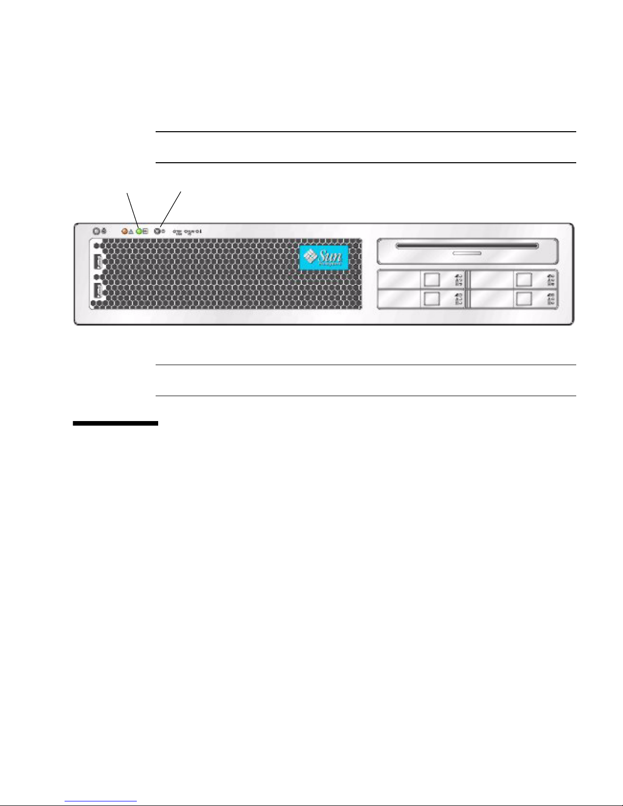
FIGURE 2-2 Front Panel of Sun Fire X4200/X4200 M2 Server
Figure Legend
1 Power/OK LED
2 Power button
21
Figure Legend
1 Power/OK LED
2 Power button
2.2 Powering Off the Server
1. Choose a method for shutting down the server from main power mode to
standby power mode.
■ Graceful shutdown: Use a nonconducting pointer or stylus to press and release
the Power button on the front panel. This causes Advanced Configuration and
Power Interface (ACPI) enabled operating systems to perform an orderly
shutdown of the operating system. Servers not running ACPI-enabled
operating systems will shut down to standby power mode immediately.
■ Emergency shutdown: Press and hold the Power button for four seconds to
force main power off and enter standby power mode.
When main power is off, the Power/OK LED on the front panel will begin
flashing, indicating that the server is in standby power mode.
Chapter 2 Powering On and Configuring BIOS Settings 2-3
Page 32

Caution – When you use the Power button to enter standby power mode, power is
still directed to the Graphics Redirect and Service Processor (GRASP) board and
power supply fans, which is indicated when the Power/OK LED is flashing. To
completely power off the server, you must disconnect the power cords from the back
panel of the server.
2.3 Configuring BIOS Settings
This section describes how to view and modify the BIOS settings.
The Basic Input/Output System (BIOS) has a Setup utility stored in the BIOS flash
memory. The Setup utility reports system information and can be used to configure
the BIOS settings. The configured data is provided with context-sensitive Help and is
stored in the system's battery-backed CMOS RAM. If the configuration stored in the
CMOS RAM is invalid, the BIOS settings will default to the original state specified at
the factory.
The first BIOS Setup menu screen is displayed. The BIOS Setup utility contains seven
menu screens, which are displayed in the following order: Main, Advanced,
PCI/PnP, Boot, Security, Chipset, and Exit.
Use the left and right arrow keys to move sequentially back and forth through the
seven screens. Fields that can be reconfigured are displayed in color. All other fields
are nonconfigurable. Use the up and down arrow keys to scroll through a menu. Use
the Tab key to move back and forth across columns.
2.3.1 Changing the Configuration of a BIOS Menu Item
You can change the BIOS configuration in several different interfaces.
■ Use a USB keyboard, a mouse, and a VGA monitor connected directly to the
server.
■ Use the remote video console of the ILOM Service Processor and redirect the
server’s console output. See Section B.2, “Redirecting Console Output” on
page B-2.
■ Use a terminal (or terminal emulator connected to a computer) through the serial
port on the back panel of the server.
2-4 Sun Fire X4100/X4100 M2 and X4200/X4200 M2 Servers Service Manual • August 2009
Page 33

1. To change the system parameters, enter the BIOS Setup utility by pressing the
F2 key while the system is performing the power-on self-test (POST).
POST testing is indicated when the Power/OK LEDs on the front and back panels
go into slow-blink mode.
2. Highlight the field to be modified using the arrow and Tab keys.
3. Press Enter to select the field.
A dialog box is displayed. The box presents you with the options that are available
for the setup field that you have chosen.
4. Modify the setup field and close the screen.
5. If you need to modify other setup parameters, use the arrow and Tab keys to
navigate to the desired screen and menu item, then repeat steps 1 through 3.
Otherwise, go to Step 6.
6. Press and release the right arrow key until the Exit menu screen is displayed.
7. Follow the instructions on the Exit menu screen to save your changes and exit
the Setup utility.
2.3.2 PCI Card Slot Boot Priority
Refer to the section that corresponds to your version of the server:
■ “Sun Fire X4100/X4200 Servers PCI Slot Boot Priority” on page 2-5
■ “Sun Fire X4100 M2/X4200 M2 Servers PCI Slot Boot Priority” on page 2-5
See Section 3.12.16, “Replacing PCI Cards” on page 3-72 for the locations of the PCI
slots.
Sun Fire X4100/X4200 Servers PCI Slot Boot Priority
The slots for the PCI cards are detected by the BIOS during startup in the following
order:
■ Sun Fire X4100: PCIX Slot 0, PCIX Slot 1
■ Sun Fire X4200: PCIX Slot 0, PCIX Slot 2, PCIX Slot 3, PCIX Slot 4, PCIX Slot 1
Sun Fire X4100 M2/X4200 M2 Servers PCI Slot Boot Priority
The slots for the PCI cards are detected by the BIOS during startup in the following
order:
Chapter 2 Powering On and Configuring BIOS Settings 2-5
Page 34
■ Sun Fire X4100: PCIE Slot 0, PCIE Slot 1
■ Sun Fire X4200: PCIE Slot 0, PCIE Slot 1, PCIE Slot 3, PCIE Slot 4, PCIX Slot 2
2.3.3 Ethernet Port Device and Driver Naming
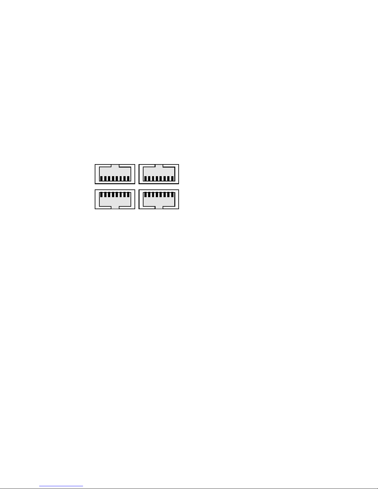
These servers each have four 10/100/1000BASE-T Gigabit Ethernet ports. The chassis
labeling of the physical ports is shown in
FIGURE 2-3 Ethernet Port Chassis Labeling Designations
FIGURE 2-3.
NET 2
NET 0
NET 3
NET 1
The device naming for the Ethernet ports differ according to the OS. Refer to the
section below that applies to your server:
■ “Sun Fire X4100/X4200 Ethernet Port Mapping” on page 6
■ “Sun Fire X4100 M2/X4200 M2 Ethernet Port Mapping” on page 7
2-6 Sun Fire X4100/X4100 M2 and X4200/X4200 M2 Servers Service Manual • August 2009
Page 35
Sun Fire X4100/X4200 Ethernet Port Mapping
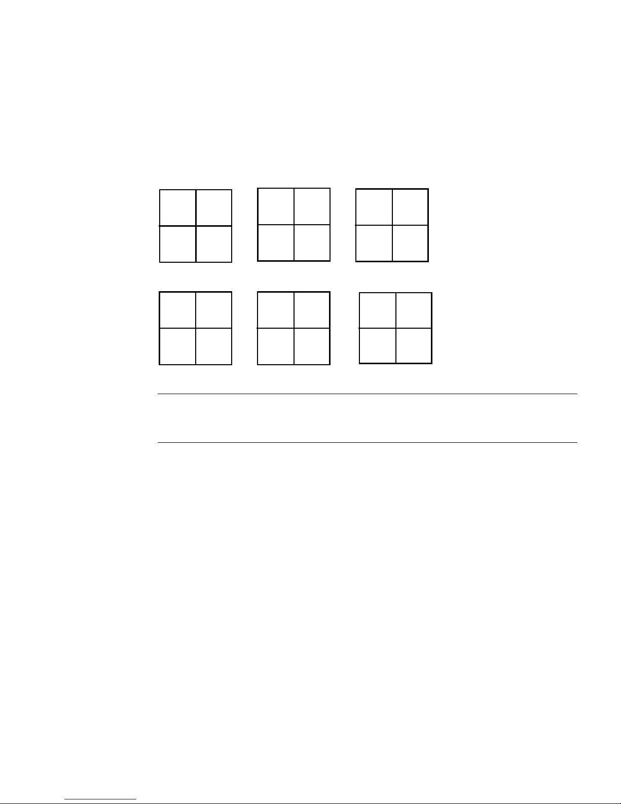
FIGURE 2-4 shows how various operating systems and interfaces name the four
Ethernet ports shown in
FIGURE 2-4 Sun Fire X4100/X4200 Ethernet Port Mapping
BIOS Solaris 10 RHEL
FIGURE 2-3.
slot
110
slot
108
slot
111
slot
109
e1000
g2
e1000g0e1000
SUSE Windows 2003
eth2
eth0 eth1
eth3
net3
net net2
e1000
g3
g1
net4
eth2
eth3
eth0 eth1
VMWare ESX 3.0.1
vmnic# vmnic#
vmnic# vmnic#
Note – VMWare ESX 3.0.1: The Ethernet port that the user assigns to the service
console will be vmnic0. Other ports are mapped by ascending order of PCI bus
enumerations.
Chapter 2 Powering On and Configuring BIOS Settings 2-7
Page 36

Sun Fire X4100 M2/X4200 M2 Ethernet Port Mapping
FIGURE 2-5 shows how various operating systems and interfaces name the four
Ethernet ports shown in
FIGURE 2-5 Sun Fire X4100 M2/X4200 M2 Ethernet Port Mapping
BIOS Solaris 10 RHEL4/RHEL5
FIGURE 2-3.
slot
110
slot
108
RHEL3/SUSE
eth2
eth0 eth1
slot
111
slot
109
eth3
e1000
g0
nge0 nge1
Windows 2003
net3
net net2
e1000
g1
net4
eth0
eth2 eth3
VMWare ESX 3.0.1
vmnic# vmnic#
vmnic# vmnic#
eth1
Note – VMWare ESX 3.0.1: The Ethernet port that the user assigns to the service
console will be vmnic0. Other ports are mapped by ascending order of PCI bus
enumerations.
2.3.4 Ethernet Port (NIC) Boot Priority
Refer to the section that corresponds to your version of the server:
Sun Fire X4100/X4200 Servers Ethernet Port Boot Priority
The order in which the BIOS detects the Ethernet ports during bootup and the
corresponding drivers that control those ports are listed below:
1. NET 0 (Intel NIC 0)
2. NET 1 (Intel NIC 1)
3. NET 2 (Intel NIC 2)
4. NET 3 (Intel NIC 3)
2-8 Sun Fire X4100/X4100 M2 and X4200/X4200 M2 Servers Service Manual • August 2009
Page 37

Sun Fire X4100 M2/X4200 M2 Servers Ethernet Port Boot Priority
The order in which the BIOS detects the Ethernet ports during bootup and the
corresponding drivers that control those ports are listed below:
1. NET 0 (NVIDIA CK8-04 NIC)
2. NET 1 (NVIDIA IO-04 NIC)
3. NET 2 (Intel NIC)
4. NET 3 (Intel NIC)
2.3.5 BIOS Option ROM Size Limitation
The BIOS Option ROM is 128 KB. Of these 128 KB, approximately 80 KB are used by
the VGA controller, the LSI controller, and the network interface card.
Approximately 48 KB remain for the Option ROM.
2.3.6 BIOS Setup Screen Overview
TABLE 2-1 contains summary descriptions of the seven top-level BIOS setup screens.
TABLE 2-1 BIOS Setup Screens Summary
Screen Description
Main General system information.
Advanced Configuration interface for the CPUs, IDE, SuperIO, ACPI, Event
Log, HyperTransport, IPMI, MPS, PCI-Express, PowerNow!, Remote
Access, and USB.
PCI/PnP Plug-and-Play (PnP) devices can be configured by the BIOS (default)
or by the operating system (if applicable).
Boot Configure the boot device priority (hard disk drives and the ATAPI
DVD-ROM drive).
Security Install or change the user and supervisor passwords.
Chipset Configuration options for the NorthBridge and SouthBridge devices
and PCI-X devices.
Note that the Memory Chipkill option is enabled by default. Enabling
Chipkill improves system reliability, but degrades system
performance under specific applications.
Exit Save or discard changes.
Chapter 2 Powering On and Configuring BIOS Settings 2-9
Page 38
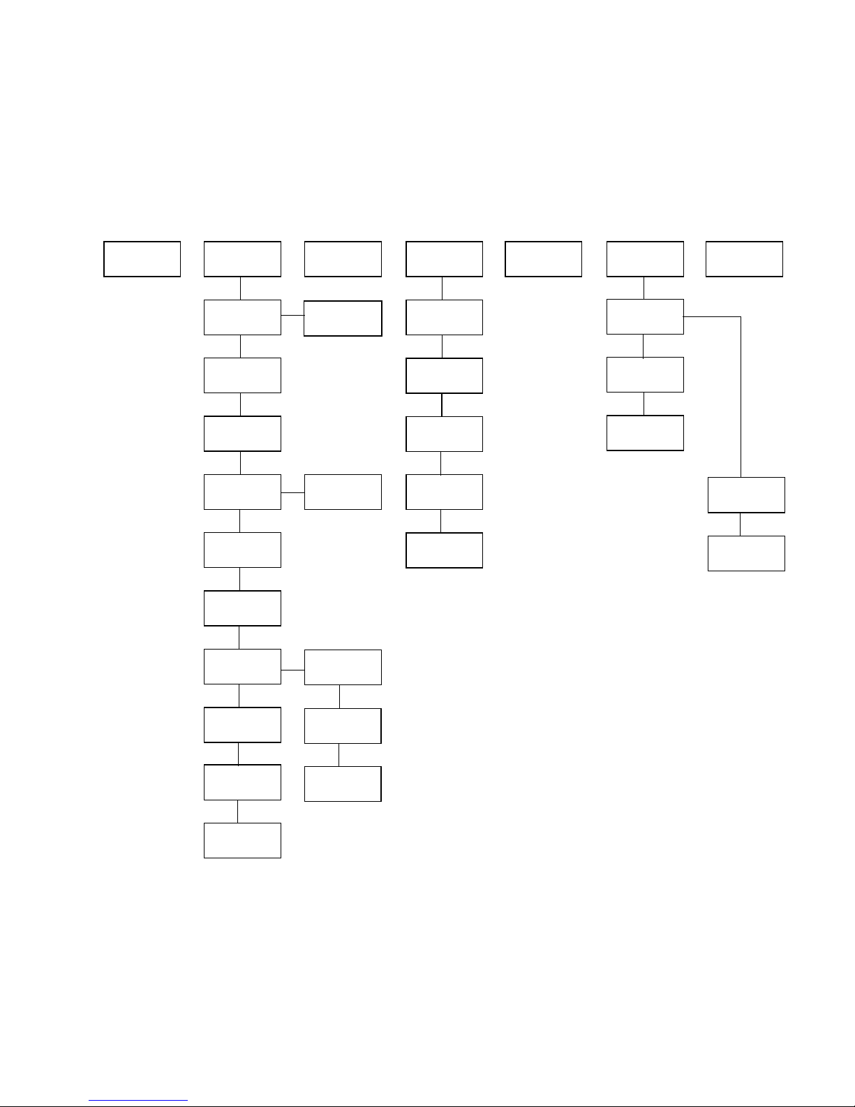
FIGURE 2-6 and FIGURE 2-7 summarize the BIOS Configuration Utility menu tree, with
differences between server models noted. See Section 2.3.6.1, “BIOS Setup Menu
Screens” on page 2-12 for examples of each of these screens.
FIGURE 2-6 Sun Fire X4100/X4200 BIOS Configuration Utility Menu Tree
Main menu
Advanced
menu
CPU
Configuration
IDE
Configuration
Super I/O
Configuration
ACPI
Settings
Event
Logging
HyperTransport
Configuration
PCI/PnP
menu
PowerNow!
Configuration
ACPI
Configuration
Boot menu
Boot
Settings
Boot Device
Priority
Hard Disk
Drives
Removable
Drives
CD/DVD
Drives
Security
menu
Chipset
menu
NorthBridge
Configuration
SouthBridge
Configuration
PCI-X
Configuration *
* This screen is
available only on
Sun Fire X4100/
X4200 servers.
Exit menu
Memory
Configuration
ECC
Configuration
IPMI
Configuration
MPS
Configuration
RemoteAccess
Configuration
USB
Configuration
BMC
Event Log
LAN
Configuration
PEF
Configuration
2-10 Sun Fire X4100/X4100 M2 and X4200/X4200 M2 Servers Service Manual • August 2009
Page 39
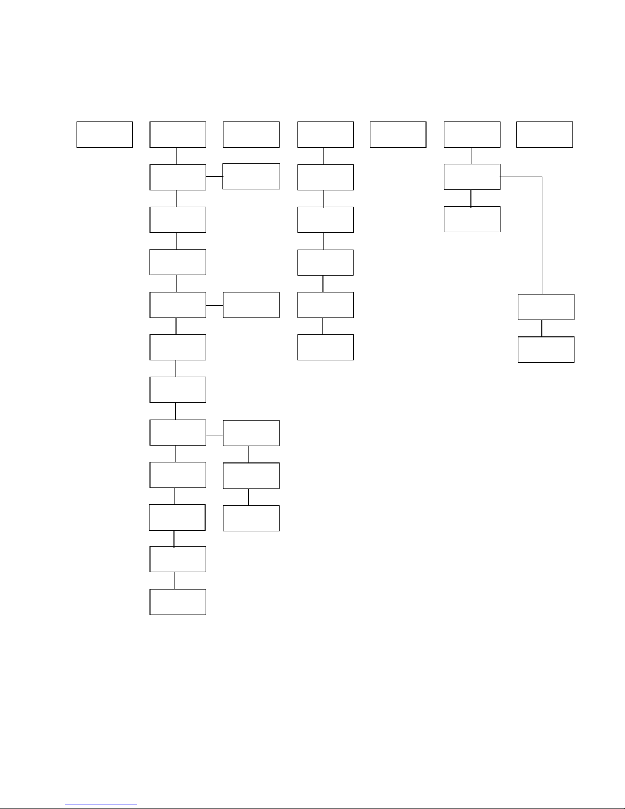
FIGURE 2-7 Sun Fire X4100 M2/X4200 M2 BIOS Configuration Utility Menu Tree
Main menu
Advanced
menu
CPU
Configuration
IDE
Configuration
Super I/O
Configuration
ACPI
Settings
Event
Logging
HyperTransport
Configuration
PCI/PnP
menu
PowerNow!
Configuration
ACPI
Configuration
Boot menu
Boot
Settings
Boot Device
Priority
Hard Disk
Drives
Removable
Drives
CD/DVD
Drives
Security
menu
Chipset
menu
NorthBridge
Configuration
SouthBridge
Configuration
Exit menu
Memory
Configuration
ECC
Configuration
* This screen
is available
only on Sun
Fire X4100
M2/X4200
M2 servers.
IPMI
Configuration
MPS
Configuration
PCI Express
Configuration*
RemoteAccess
Configuration
USB
Configuration
BMC
Event Log
LAN
Configuration
PEF
Configuration
Chapter 2 Powering On and Configuring BIOS Settings 2-11
Page 40

2.3.6.1 BIOS Setup Menu Screens
This section shows sample BIOS setup menu screens with optimal default settings
where applicable.
Note – The screens shown are examples. Actual version numbers are subject to
change over the life of the product.
BIOS Main Menu Screen
Main Advanced PCIPnP Boot Security Chipset Exit
********************************************************************************
* System Overview ** Use [ENTER], [TAB] *
* ***************************************************** or [SHIFT-TAB] to *
* AMIBIOS ** select a field. *
* Version : 08.00.10 ** *
* Build Date: 06/22/05 ** Use [+] or [-] to *
* ID : 0ABGA018 ** configure system Time. *
* ** *
* Product Name : Sun Fire X4200 **
* System Serial Number : 0525AMF002 *
* BMC Firmware Revision : 1.00 ** *
* ** *
* Processor ** *
* Type : AMD Opteron(tm) Processor 254 ** ** Select Screen *
* Speed : 2.8 GHz ** ** Select Item *
* Count : 2 ** +- Change Field *
* ** Tab Select Field *
* System Memory ** F1 General Help *
* Size : 3.0 GB ** F10 Save and Exit *
* ** ESC Exit *
* System Time [14:23:56] ** ESC Exit *
* System Date [Wed 07/20/2005] ** *
********************************************************************************
2-12 Sun Fire X4100/X4100 M2 and X4200/X4200 M2 Servers Service Manual • August 2009
Page 41

2.3.6.2 BIOS Advanced Menu Main Screens
Sun Fire X4100/X4200 Servers
Main Advanced PCIPnP Boot Security Chipset Exit
********************************************************************************
* Advanced Settings * Options for CPU *
* *************************************************** * *
* WARNING: Setting wrong values in below sections * *
* may cause system to malfunction. * *
* * CPU Configuration * *
* * IDE Configuration * *
* * SuperIO Configuration * *
* * ACPI Configuration * *
* * Event Log Configuration * *
* * Hyper Transport Configuration * *
* * IPMI 2.0 Configuration * *
* * MPS Configuration * ** Select Screen *
* * AMD PowerNow Configuration * ** Select Item *
* * Remote Access Configuration * Enter Go to Sub Screen *
* * USB Configuration * F1 General Help *
* * F10 Save and Exit *
* * ESC Exit *
********************************************************************************
Chapter 2 Powering On and Configuring BIOS Settings 2-13
Page 42

Sun Fire X4100 M2/X4200 M2 Servers
Main Advanced PCIPnP Boot Security Chipset Exit
********************************************************************************
* Advanced Settings * Options for CPU *
* *************************************************** * *
* WARNING: Setting wrong values in below sections * *
* may cause system to malfunction. * *
* * CPU Configuration * *
* * IDE Configuration * *
* * SuperIO Configuration * *
* * ACPI Configuration * *
* * Event Log Configuration * *
* * Hyper Transport Configuration * *
* * IPMI 2.0 Configuration * *
* * MPS Configuration * ** Select Screen *
* * PCI Express Configuration * *
* * AMD PowerNow Configuration * ** Select Item *
* * Remote Access Configuration * Enter Go to Sub Screen *
* * USB Configuration * F1 General Help *
* * F10 Save and Exit *
* * ESC Exit *
********************************************************************************
2-14 Sun Fire X4100/X4100 M2 and X4200/X4200 M2 Servers Service Manual • August 2009
Page 43

2.3.6.3 BIOS Advanced Menu CPU Configuration Screen
Sun Fire X4100/X4200 Servers
Advanced
********************************************************************************
* CPU Configuration * This option should *
* Module Version: 14.05 * remain disabled for *
* Physical Count: 2 * the normal operation. *
* Logical Count : 2 * The driver developer *
* *************************************************** * may enable it for *
* AMD Opteron(tm) Processor 254 * testing purpose. *
* Revision: E4 * *
* Cache L1: 64KB * *
* Cache L2: 1024KB * *
* Speed : 2800MHz * *
* Current FSB Multiplier: 14x * *
* Maximum FSB Multiplier: 14x * *
* Able to Change Freq. : Yes * ** Select Screen *
* uCode Patch Level : None Required * ** Select Item *
* * +- Change Option *
* GART Error Reporting [Disabled] * F1 General Help *
* MTRR Mapping [Continuous] * F10 Save and Exit *
* Speculative TLB Reload [Enabled] * ESC Exit *
* * *
********************************************************************************
Chapter 2 Powering On and Configuring BIOS Settings 2-15
Page 44

Sun Fire X4100 M2/X4200 M2 Servers
Advanced
********************************************************************************
* CPU Configuration * This option should *
* Module Version: 14.05 * remain disabled for *
* Physical Count: 2 * the normal operation. *
* Logical Count : 2 * The driver developer *
* *************************************************** * may enable it for *
* AMD Opteron(tm) Processor 852 * testing purpose. *
* Revision: E4 * *
* Cache L1: 64KB * *
* Cache L2: 1024KB * *
* Speed : 2.6 GHz * *
* Current FSB Multiplier: 13x * *
* Maximum FSB Multiplier: 13x * *
* Able to Change Freq. : Yes * ** Select Screen *
* uCode Patch Level : None Required * ** Select Item *
* * +- Change Option *
* GART Error Reporting [Disabled] * F1 General Help *
* MTRR Mapping [Continuous] * F10 Save and Exit *
* CPU Overclock in MHz [200] * ESC Exit *
* Speculative TLB Reload [Enabled] * *
* * *
********************************************************************************
2-16 Sun Fire X4100/X4100 M2 and X4200/X4200 M2 Servers Service Manual • August 2009
Page 45

2.3.6.4 BIOS Advanced Menu IDE Configuration Screen
Sun Fire X4100/X4200 Servers
Advanced
********************************************************************************
* IDE Configuration * DISABLED: disables the *
* *************************************************** * integrated IDE *
* OnBoard PCI IDE Controller [Primary] * Controller. *
* * PRIMARY: enables only *
* * Primary IDE Master : [ATAPI CDROM] * the Primary IDE *
* * Primary IDE Slave : [Not Detected] * Controller. *
* * SECONDARY: enables *
* Hard Disk Write Protect [Disabled] * only the Secondary IDE *
* IDE Detect Time Out (Sec) [5] * Controller. *
* * BOTH: enables both IDE *
* * Controllers. *
* * *
* * ** Select Screen *
* * ** Select Item *
* * +- Change Option *
* * F1 General Help *
* * F10 Save and Exit *
* * ESC Exit *
* * *
* * *
********************************************************************************
Chapter 2 Powering On and Configuring BIOS Settings 2-17
Page 46

Sun Fire X4100 M2/X4200 M2 Servers
Advanced
********************************************************************************
* IDE Configuration * DISABLED: disables the *
* *************************************************** * integrated IDE *
* OnBoard PCI IDE Controller [Primary] * Controller. *
* * PRIMARY: enables only *
* * Primary IDE Master : [ATAPI CDROM] * the Primary IDE *
* * Primary IDE Slave : [Not Detected] * Controller. *
* * SECONDARY: enables *
* Hard Disk Write Protect [Disabled] * only the Secondary IDE *
* IDE Detect Time Out (Sec) [5] * Controller. *
* * BOTH: enables both IDE *
* ATA(PI) 80 Pin Cable Detection [Disabled] * Controllers. *
* SATA0 IDE Interface [Disabled] * *
* SATA1 IDE Interface [Disabled] * ** Select Screen *
* IO4 SATA0 IDE Interface [Disabled] * ** Select Item *
* IO4 SATA1 IDE Interface [Disabled] * +- Change Option *
* First Boot Device from [P-ATA] * F1 General Help *
* * F10 Save and Exit *
* * ESC Exit *
* * *
********************************************************************************
2-18 Sun Fire X4100/X4100 M2 and X4200/X4200 M2 Servers Service Manual • August 2009
Page 47

2.3.6.5 BIOS Advanced Menu SuperIO Chipset Configuration Screen
Advanced
********************************************************************************
* Configure Smc27X Super IO Chipset * Allows BIOS to Select *
* *************************************************** * Serial Port1 Base *
* Serial Port1 Address [3F8/IRQ4] * Addresses. *
* * *
* * *
* * *
* * *
* * *
* * *
* * *
* * *
* * *
* * ** Select Screen *
* * ** Select Item *
* * +- Change Option *
* * F1 General Help *
* * F10 Save and Exit *
* * ESC Exit *
* * *
* * *
********************************************************************************
Chapter 2 Powering On and Configuring BIOS Settings 2-19
Page 48

2.3.6.6 BIOS Advanced Menu ACPI Settings Screen
Advanced
********************************************************************************
* ACPI Settings * Yes / No *
* *************************************************** * ACPI support for *
* ACPI Aware O/S [Yes] * Operating System. *
* * *
* * Advanced ACPI Configuration * Yes: If OS *
* * supports ACPI. *
* * *
* * No: If OS *
* * does not support *
* * ACPI. *
* * *
* * *
* * ** Select Screen *
* * ** Select Item *
* * +- Change Option *
* * F1 General Help *
* * F10 Save and Exit *
* * ESC Exit *
* * *
* * *
********************************************************************************
2-20 Sun Fire X4100/X4100 M2 and X4200/X4200 M2 Servers Service Manual • August 2009
Page 49

2.3.6.7 BIOS Advanced Menu ACPI Configuration Screen
Advanced
********************************************************************************
* Advanced ACPI Configuration * Enable RSDP pointers *
* *************************************************** * to 64-bit Fixed System *
* ACPI 2.0 Features [Yes] * Description Tables. *
* ACPI APIC support [Enabled] * *
* ACPI SRAT Table [Enabled] * *
* AMI OEMB table [Enabled] * *
* Headless mode [Enabled] * *
* * *
* * *
* * *
* * *
* * *
* * ** Select Screen *
* * ** Select Item *
* * +- Change Option *
* * F1 General Help *
* * F10 Save and Exit *
* * ESC Exit *
* * *
* * *
********************************************************************************
Chapter 2 Powering On and Configuring BIOS Settings 2-21
Page 50

2.3.6.8 BIOS Advanced Menu Event Logging Details Screen
Advanced
********************************************************************************
* Event Logging details * View all unread events *
* *************************************************** * on the Event Log. *
* View Event Log * *
* Mark all events as read * *
* Clear Event Log * *
* * *
* * *
* * *
* * *
* * *
* * *
* * *
* * ** Select Screen *
* * ** Select Item *
* * Enter Go to Sub Screen *
* * F1 General Help *
* * F10 Save and Exit *
* * ESC Exit *
* * *
* * *
********************************************************************************
2-22 Sun Fire X4100/X4100 M2 and X4200/X4200 M2 Servers Service Manual • August 2009
Page 51

2.3.6.9 BIOS Advanced Menu HyperTransport Configuration Screen
Sun Fire X4100/X4200 Servers
Advanced
********************************************************************************
* Hyper Transport Configuration * The HyperTransport *
* *************************************************** * link will run at this *
* * speed if it is slower *
* CPU0:CPU1 HT Link Speed [Auto] * than or equal to the *
* CPU0:CPU1 HT Link Width [Auto] * system clock and the *
* * board is capable. *
* CPU0:PCI-X0 HT Link Speed [Auto] * *
* CPU0:PCI-X0 HT Link Width [Auto] * *
* * *
* CPU0:PCI-X1 HT Link Speed [Auto] * *
* CPU0:PCI-X1 HT Link Width [Auto] * *
* * *
* * ** Select Screen *
* * ** Select Item *
* * +- Change Option *
* * F1 General Help *
* * F10 Save and Exit *
* * ESC Exit *
********************************************************************************
Chapter 2 Powering On and Configuring BIOS Settings 2-23
Page 52

Sun Fire X4100 M2/X4200 M2 Servers
Advanced
********************************************************************************
* Hyper Transport Configuration * The HyperTransport *
* *************************************************** * link will run at this *
* * speed if it is slower *
* CPU0:CPU1 HT Link Speed [Auto] * than or equal to the *
* CPU0:CPU1 HT Link Width [Auto] * system clock and the *
* * board is capable. *
* CPU0:CK804 HT Link Speed [Auto] * *
* CPU0:CK804 HT Link Width [Auto] * *
* * *
* CPU0:CPU1 HT Link Speed [Auto] * *
* CPU0:CPU1 HT Link Width [Auto] * *
* * *
* CPU1:PCI-X HT Link Speed [Auto] * *
* CPU1:PCI-X HT Link Width [Auto] * *
* * ** Select Screen *
* PCI-X:IO4 HT Link Speed [Auto] * ** Select Item *
* PCI-X:IO4 HT Link Width [Auto] * +- Change Option *
* * F1 General Help *
* * F10 Save and Exit *
* * ESC Exit *
* * *
********************************************************************************
2-24 Sun Fire X4100/X4100 M2 and X4200/X4200 M2 Servers Service Manual • August 2009
Page 53

2.3.6.10 BIOS Advanced Menu IPMI Configuration Screen
Advanced
********************************************************************************
* IPMI 2.0 Configuration * View all events in the *
* *************************************************** * BMC Event Log. *
* Status Of BMC Working * *
* * View BMC System Event Log * It will take up to *
* Reload BMC System Event Log * 60 Seconds approx. *
* Clear BMC System Event Log * to read all *
* * LAN Configuration * BMC SEL records. *
* * PEF Configuration * *
* BMC Watch Dog Timer Action [Disabled] * *
* * *
* * ** Select Screen *
* * ** Select Item *
* * Enter Go to Sub Screen *
* * F1 General Help *
* * F10 Save and Exit *
* * ESC Exit *
* * *
********************************************************************************
Chapter 2 Powering On and Configuring BIOS Settings 2-25
Page 54

2.3.6.11 BIOS Advanced Menu IPMI, View BMC Event Log Screen
Advanced
********************************************************************************
* Total Number Of Entries: 36 * Use +/- to traverse *
* *************************************************** * the event log. *
* SEL Entry Number: [01] * *
* SEL Record ID: 0100 * *
* SEL Record Type: 02 (System Event) * *
* Event Timestamp: 1166s from SEL init * *
* Generator ID: 0020 * *
* Event Message Format Ver: 04 (IPMI ver 1.5) * *
* Event Sensor Type: 25 (Entity Presence) * *
* Event Sensor Number: 1F * *
* Event Dir Type: 08 * *
* Event Data: 00 FF FF * *
* * ** Select Screen *
* * ** Select Item *
* * +- Change Option *
* * F1 General Help *
* * F10 Save and Exit *
* * ESC Exit *
********************************************************************************
2-26 Sun Fire X4100/X4100 M2 and X4200/X4200 M2 Servers Service Manual • August 2009
Page 55

2.3.6.12 BIOS Advanced Menu IPMI, LAN Configuration Screen
Advanced
********************************************************************************
* LAN Configuration. * Enter for IP Address *
* *************************************************** * Configuration. *
* Channel Number [01] * *
* Channel Number Status: Channel number is OK * *
* * IP Address * *
* * MAC Address * *
* * Subnet Mask * *
* * *
* * *
* * *
* * *
* * *
* * ** Select Screen *
* * ** Select Item *
* * Enter Go to Sub Screen *
* * F1 General Help *
* * F10 Save and Exit *
* * ESC Exit *
* * *
* * *
********************************************************************************
Chapter 2 Powering On and Configuring BIOS Settings 2-27
Page 56

2.3.6.13 BIOS Advanced Menu IPMI, PEF Configuration Screen
Advanced
********************************************************************************
* Set PEF Configuration Parameters Command. * Enable or Disable PEF *
* *************************************************** * Support. *
* PEF SUPPORT [Enabled] * Refer Table 24.6 of *
* * PEF Action Global Control * IPMI Specification 1.5 *
* Alert Startup Delay [Disabled] * *
* Startup Delay [Disabled] * *
* Event Message For PEF Action [Disabled] * *
* * *
* * *
* * *
* * *
* * ** Select Screen *
* * ** Select Item *
* * +- Change Option *
* * F1 General Help *
* * F10 Save and Exit *
* * ESC Exit *
* * *
********************************************************************************
2-28 Sun Fire X4100/X4100 M2 and X4200/X4200 M2 Servers Service Manual • August 2009
Page 57

2.3.6.14 BIOS Advanced Menu MPS Configuration Screen
Advanced
********************************************************************************
* MPS Configuration * MPS Revision *
* *************************************************** * *
* MPS Revision [1.4] * *
* * *
* * *
* * *
* * *
* * *
* * *
* * *
* * *
* * *
* * ** Select Screen *
* * ** Select Item *
* * +- Change Option *
* * F1 General Help *
* * F10 Save and Exit *
* * ESC Exit *
* * *
* * *
********************************************************************************
Chapter 2 Powering On and Configuring BIOS Settings 2-29
Page 58

2.3.6.15 BIOS Advanced Menu PCI Express Configuration Screen
Sun Fire X4100 M2/X4200 M2 Servers Only
Advanced
********************************************************************************
* PCI Express Configuration * *
* *************************************************** * Enable/Disable *
* * PCI Express L0s and *
* Active State Power Management [Disabled] * L1 link power *
* * states *
* * *
* * *
* * *
* * *
* * ** Select Screen *
* * ** Select Item *
* * +- Change Option *
* * F1 General Help *
* * F10 Save and Exit *
* * ESC Exit *
* * *
********************************************************************************
2-30 Sun Fire X4100/X4100 M2 and X4200/X4200 M2 Servers Service Manual • August 2009
Page 59

2.3.6.16 BIOS Advanced Menu, AMD PowerNow Configuration
Advanced
********************************************************************************
* AMD PowerNow Configuration * Enabled/Disabled *
* *************************************************** * PowerNow *
* PowerNow [Enabled] * *
* * *
* * *
* * *
* * *
* * *
* * *
* * *
* * *
* * *
* * ** Select Screen *
* * ** Select Item *
* * +- Change Option *
* * F1 General Help *
* * F10 Save and Exit *
* * ESC Exit *
* * *
* * *
********************************************************************************
Chapter 2 Powering On and Configuring BIOS Settings 2-31
Page 60

2.3.6.17 BIOS Advanced Menu Remote Access Configuration Screen
Advanced
********************************************************************************
* Configure Remote Access type and parameters * Select Remote Access *
* *************************************************** * type. *
* Remote Access [Enabled] * *
* * *
* Serial port number [COM1] * *
* Base Address, IRQ [3F8h, 4] * *
* Serial Port Mode [09600 8,n,1] * *
* Flow Control [None] * *
* Redirection After BIOS POST [Always] * *
* Terminal Type [ANSI] * *
* VT-UTF8 Combo Key Support [Enabled] * *
* Sredir Memory Display Delay [No Delay] * *
* * ** Select Screen *
* * ** Select Item *
* * +- Change Option *
* * F1 General Help *
* * F10 Save and Exit *
* * ESC Exit *
* * *
* * *
********************************************************************************
2-32 Sun Fire X4100/X4100 M2 and X4200/X4200 M2 Servers Service Manual • August 2009
Page 61

2.3.6.18 BIOS Advanced Menu USB Configuration Screen
Sun Fire X4100/X4200 Servers
Advanced
********************************************************************************
* USB Configuration * Enables support for *
* *************************************************** * legacy USB. AUTO *
* Module Version - 2.23.0-7.4 * option disables *
* * legacy support if *
* USB Devices Enabled : * no USB devices are *
* 1 Keyboard, 1 Mouse, 1 Hub, 2 Drives * connected. *
* * *
* Legacy USB Support [Enabled] * *
* Hotplug USB FDD Support [Auto] * *
* Hotplug USB CDROM Support [Auto] * *
* * *
* * USB Mass Storage Device Configuration * *
* * ** Select Screen *
* * ** Select Item *
* * +- Change Option *
* * F1 General Help *
* * F10 Save and Exit *
* * ESC Exit *
********************************************************************************
Chapter 2 Powering On and Configuring BIOS Settings 2-33
Page 62

Sun Fire X4100 M2/X4200 M2 Servers
Advanced
********************************************************************************
* USB Configuration * Enables support for *
* *************************************************** * legacy USB. AUTO *
* Module Version - 2.24.0-F.4 * option disables *
* * legacy support if *
* USB Devices Enabled : * no USB devices are *
* 1 Keyboard, 1 Mouse, 1 Hub, 2 Drives * connected. *
* * *
* USB Controller Support [USB1.1+USB2.0] * *
* Legacy USB Support [Enabled] * *
* USB 2.0 Controller Mode [HiSpeed] * *
* BIOS EHCI Hand-off [Enabled] * *
* Hotplug USB FDD Support [Auto] * *
* Hotplug USB CDROM Support [Auto] * *
* * *
* * USB Mass Storage Device Configuration * *
* * ** Select Screen *
* * ** Select Item *
* * +- Change Option *
* * F1 General Help *
* * F10 Save and Exit *
* * ESC Exit *
********************************************************************************
2-34 Sun Fire X4100/X4100 M2 and X4200/X4200 M2 Servers Service Manual • August 2009
Page 63

2.3.6.19 BIOS PCI/PnP Menu
Sun Fire X4100/X4200 Servers
Main Advanced PCIPnP Boot Security Chipset Exit
********************************************************************************
* Advanced PCI/PnP Settings ** NO: lets the BIOS *
* ***************************************************** configure all the *
* WARNING: Setting wrong values in below sections ** devices in the system. *
* may cause system to malfunction. ** YES: lets the *
* ** operating system *
* Plug & Play O/S [No] ** configure Plug and *
* PCI Latency Timer [64] ** Play (PnP) devices not *
* Allocate IRQ to PCI VGA [Yes] ** required for boot if *
* Palette Snooping [Disabled] ** your system has a Plug *
* PCI IDE BusMaster [Disabled] ** and Play operating *
* OffBoard PCI/ISA IDE Card [Auto] ** system. *
* Onboard LSI SAS/SATA [Enabled] ** *
* Onboard PCI NIC [Enabled] ** ** Select Screen *
* PCIX SLOT1 [Enabled] ** ** Select Item *
* PCIX SLOT2 [Enabled] ** +- Change Option *
* PCIX SLOT3 [Enabled] ** F1 General Help *
* PCIX SLOT4 [Enabled] ** F10 Save and Exit *
* PCIX SLOT5 [Enabled] ** ESC Exit *
* Onboard PCI NIC MAC Address ** *
* GE NIC 1 : 00 03 BA CD 51 39 ** *
* GE NIC 2 : 00 03 BA CD 51 38 ** Available: Specified *
* GE NIC 3 : 00 03 BA CD 51 3B ** DMA is available to be *
* GE NIC 3 : 00 03 BA CD 51 3B ** used by PCI/PnP *
* ** devices. *
* IRQ3 [Available] ** Reserved: Specified *
* IRQ4 [Reserved] ** DMA is reserved for *
* IRQ5 [Available] ** use by legacy ISA *
* IRQ7 [Available] ** devices. *
* IRQ9 [Available] ** *
* IRQ10 [Available] ** *
* IRQ11 [Available] ** *
* IRQ14 [Available] ** *
* IRQ15 [Available] ** ** Select Screen *
* ** ** Select Item *
* DMA Channel 0 [Available] ** +- Change Option *
* DMA Channel 1 [Available] ** F1 General Help *
* DMA Channel 3 [Available] ** F10 Save and Exit *
* DMA Channel 5 [Available] ** ESC Exit *
* DMA Channel 6 [Available] ** *
* DMA Channel 7 [Available] ** *
* ** *
* Reserved Memory Size [Disabled] ** *
********************************************************************************
Chapter 2 Powering On and Configuring BIOS Settings 2-35
Page 64

Sun Fire X4100 M2/X4200 M2 Servers
Main Advanced PCIPnP Boot Security Chipset Exit
********************************************************************************
* Advanced PCI/PnP Settings ** NO: lets the BIOS *
* ***************************************************** configure all the *
* WARNING: Setting wrong values in below sections ** devices in the system. *
* may cause system to malfunction. ** *
* ** YES: lets the *
* Clear NVRAM [No] ** operating system *
* Plug & Play O/S [No] ** configure Plug and *
* PCI Latency Timer [64] ** Play (PnP) devices not *
* Allocate IRQ to PCI VGA [Yes] ** required for boot if *
* Palette Snooping [Disabled] ** your system has a Plug *
* PCI IDE BusMaster [Disabled] ** and Play operating *
* OffBoard PCI/ISA IDE Card [Auto] ** system. *
* PCI Option ROM control [Enabled] ** *
* Scanning onboard SAS/SATA ROM [Enabled] ** *
* Scanning onboard NIC OPROM [Enabled] ** ** Select Screen *
* Scanning OPROM on PCIE SLOT0 [Enabled] ** ** Select Item *
* Scanning OPROM on PCIE SLOT1 [Enabled] ** +- Change Option *
* Scanning OPROM on PCIX SLOT2 [Enabled] ** F1 General Help *
* Scanning OPROM on PCIE SLOT3 [Enabled] ** F10 Save and Exit *
* Scanning OPROM on PCIE SLOT4 [Enabled] ** ESC Exit *
* Onboard PCI NIC MAC Address ** *
* Nvidia CK804 NIC 1 : 00 03 BA CD 51 39 ** *
* Nvidia IO4 NIC 2 : 00 03 BA CD 51 38 ** Available: Specified *
* Intel GiGE NIC 3 : 00 03 BA CD 51 3B ** DMA is available to be *
* Intel GiGE NIC 3 : 00 03 BA CD 51 3B ** used by PCI/PnP *
* ** devices. *
* IRQ3 [Available] ** Reserved: Specified *
* IRQ4 [Reserved] ** DMA is reserved for *
* IRQ5 [Available] ** use by legacy ISA *
* IRQ7 [Available] ** devices. *
* IRQ9 [Available] ** *
* IRQ10 [Available] ** *
* IRQ11 [Available] ** *
* IRQ14 [Available] ** *
* IRQ15 [Available] ** ** Select Screen *
* ** ** Select Item *
* DMA Channel 0 [Available] ** +- Change Option *
* DMA Channel 1 [Available] ** F1 General Help *
* DMA Channel 3 [Available] ** F10 Save and Exit *
* DMA Channel 5 [Available] ** ESC Exit *
* DMA Channel 6 [Available] ** *
* DMA Channel 7 [Available] ** *
* ** *
* Reserved Memory Size [Disabled] ** *
********************************************************************************
2-36 Sun Fire X4100/X4100 M2 and X4200/X4200 M2 Servers Service Manual • August 2009
Page 65

2.3.6.20 BIOS Boot Menu Main Screen
Main Advanced PCIPnP Boot Security Chipset Exit
********************************************************************************
* Boot Settings * Configure Settings *
* *************************************************** * during System Boot. *
* * Boot Settings Configuration * *
* * *
* * Boot Device Priority * *
* * Hard Disk Drives * *
* * Removable Drives * *
* * CD/DVD Drives * *
* * *
* * *
* * *
* * *
* * ** Select Screen *
* * ** Select Item *
* * Enter Go to Sub Screen *
* * F1 General Help *
* * F10 Save and Exit *
* * ESC Exit *
* * *
* * *
********************************************************************************
Chapter 2 Powering On and Configuring BIOS Settings 2-37
Page 66

2.3.6.21 BIOS Boot Settings Configuration Screen
Boot
********************************************************************************
* Boot Settings Configuration * Allows BIOS to skip *
* *************************************************** * certain tests while *
* Quick Boot [Disabled] * booting. This will *
* System Configuration Display [Disabled] * decrease the time *
* Quiet Boot [Disabled] * needed to boot the *
* Language [English] * system. *
* AddOn ROM Display Mode [Force BIOS] * *
* Bootup Num-Lock [On] * *
* Wait For 'F1' If Error [Disabled] * *
* Interrupt 19 Capture [Disabled] * *
* Default Boot Order [CRHB] * *
* * *
* * ** Select Screen *
* * ** Select Item *
* * +- Change Option *
* * F1 General Help *
* * F10 Save and Exit *
* * ESC Exit *
* * *
* * *
********************************************************************************
2-38 Sun Fire X4100/X4100 M2 and X4200/X4200 M2 Servers Service Manual • August 2009
Page 67

2.3.6.22 BIOS Boot Menu Boot Device Priority Screen
Sun Fire X4100/X4200 Servers
Boot
********************************************************************************
* Boot Device Priority * Specifies the boot *
* *************************************************** * sequence from the *
* * available devices. *
* 1st Boot Device [CD/DVD Drives] * *
* 2nd Boot Device [Removable Dev.] * A device enclosed in *
* 3rd Boot Device [Hard Drive] * parenthesis has been *
* 4th Boot Device [IBA GE Slot 0108 v] * disabled in the *
* 5th Boot Device [IBA GE Slot 0109 v] * corresponding type *
* 6th Boot Device [IBA GE Slot 0110 v] * menu. *
* 7th Boot Device [IBA GE Slot 0111 v] * *
* * *
* * ** Select Screen *
* * ** Select Item *
* * +- Change Option *
* * F1 General Help *
* * F10 Save and Exit *
* * ESC Exit *
* * *
********************************************************************************
Chapter 2 Powering On and Configuring BIOS Settings 2-39
Page 68

Sun Fire X4100 M2/X4200 M2 Servers
Boot
********************************************************************************
* Boot Device Priority * Specifies the boot *
* *************************************************** * sequence from the *
* * available devices. *
* 1st Boot Device [CD/DVD CDROM] * *
* 2nd Boot Device [Removable Dev.] * A device enclosed in *
* 3rd Boot Device [Hard Drive] * parenthesis has been *
* 4th Boot Device [NVidia Boot Agent:] * disabled in the *
* 5th Boot Device [2-NVidia Boot Agent] * corresponding type *
* 6th Boot Device [Network:IBA GE Slo] * menu. *
* 7th Boot Device [Network:IBA GE Slo] * *
* * *
* * ** Select Screen *
* * ** Select Item *
* * +- Change Option *
* * F1 General Help *
* * F10 Save and Exit *
* * ESC Exit *
* * *
********************************************************************************
2-40 Sun Fire X4100/X4100 M2 and X4200/X4200 M2 Servers Service Manual • August 2009
Page 69

2.3.6.23 BIOS Boot Menu Hard Disk Drives Screen
Boot
********************************************************************************
* Hard Disk Drives * Specifies the boot *
* *************************************************** * sequence from the *
* 1st Drive [#218 ID00 LUN0 FUJ] * available devices. *
* * *
* * *
* * *
* * *
* * *
* * *
* * *
* * *
* * *
* * ** Select Screen *
* * ** Select Item *
* * +- Change Option *
* * F1 General Help *
* * F10 Save and Exit *
* * ESC Exit *
* * *
* * *
********************************************************************************
Chapter 2 Powering On and Configuring BIOS Settings 2-41
Page 70

2.3.6.24 BIOS Boot Menu Removable Drives Screen
Boot
********************************************************************************
* Removable Drives * Specifies the boot *
* *************************************************** * sequence from the *
* 1st Drive [USB:AMI Virtual Fl] * available devices. *
* * *
* * *
* * *
* * *
* * *
* * *
* * *
* * *
* * *
* * ** Select Screen *
* * ** Select Item *
* * +- Change Option *
* * F1 General Help *
* * F10 Save and Exit *
* * ESC Exit *
* * *
* * *
********************************************************************************
2-42 Sun Fire X4100/X4100 M2 and X4200/X4200 M2 Servers Service Manual • August 2009
Page 71

2.3.6.25 BIOS Boot Menu CD/DVD Drives Screen
Boot
********************************************************************************
* CD/DVD Drives * Specifies the boot *
* *************************************************** * sequence from the *
* 1st Drive [CD/DVD:PM-QSI DVD] * available devices. *
* 2nd Drive [USB:AMI Virtual CD] * *
* * *
* * *
* * *
* * *
* * *
* * *
* * *
* * *
* * ** Select Screen *
* * ** Select Item *
* * +- Change Option *
* * F1 General Help *
* * F10 Save and Exit *
* * ESC Exit *
* * *
* * *
********************************************************************************
Chapter 2 Powering On and Configuring BIOS Settings 2-43
Page 72

2.3.6.26 BIOS Security Settings Menu
Main Advanced PCIPnP Boot Security Chipset Exit
********************************************************************************
* Security Settings * Install or Change the *
* *************************************************** * password. *
* Supervisor Password :Not Installed * *
* User Password :Not Installed * *
* * *
* Change Supervisor Password * *
* Change User Password * *
* Clear User Password * *
* * *
* Boot Sector Virus Protection [Disabled] * *
* * *
* * *
* * ** Select Screen *
* * ** Select Item *
* * Enter Change *
* * F1 General Help *
* * F10 Save and Exit *
* * ESC Exit *
* * *
* * *
********************************************************************************
2-44 Sun Fire X4100/X4100 M2 and X4200/X4200 M2 Servers Service Manual • August 2009
Page 73

2.3.6.27 BIOS Chipset Menu Main Screen
Sun Fire X4100/X4200 Servers
Main Advanced PCIPnP Boot Security Chipset Exit
********************************************************************************
* * Options for NB *
* * NorthBridge Configuration * *
* * SouthBridge Configuration * *
* * PCI-X Configuration * *
* * *
* * *
* * *
* * *
* * ** Select Screen *
* * ** Select Item *
* * Enter Go to Sub Screen *
* * F1 General Help *
* * F10 Save and Exit *
* * ESC Exit *
* * *
* * *
********************************************************************************
Sun Fire X4100 M2/X4200 M2 Servers
Main Advanced PCIPnP Boot Security Chipset Exit
********************************************************************************
* * Options for NB *
* * NorthBridge Configuration * *
* * SouthBridge Configuration * *
* * * *
* * *
* * *
* * *
* * *
* * *
* * ** Select Screen *
* * ** Select Item *
* * Enter Go to Sub Screen *
* * F1 General Help *
* * F10 Save and Exit *
* * ESC Exit *
* * *
* * *
********************************************************************************
Chapter 2 Powering On and Configuring BIOS Settings 2-45
Page 74

2.3.6.28 BIOS Chipset Menu NorthBridge Configuration Screen
Chipset
********************************************************************************
* NorthBridge Chipset Configuration * *
* *************************************************** * *
* * Memory Configuration * *
* * ECC Configuration * *
* Power Down Control [Auto] * *
* *************************************************** * *
* Memory Timing Parameters [CPU Node 0] * *
* Memory CLK :200 MHz * *
* CAS Latency(Tcl) :3.0 * *
* RAS/CAS Delay(Trcd) :3 CLK * *
* Min Active RAS(Tras) :8 CLK * *
* Row Precharge Time(Trp):3 CLK * ** Select Screen *
* RAS/RAS Delay(Trrd) :2 CLK * ** Select Item *
* Row Cycle (Trc) :11 CLK * Enter Go to Sub Screen *
* Row Refresh Cycle(Trfc):14 CLK * F1 General Help *
* Read Write Delay(Trwt) :4 CLK * F10 Save and Exit *
* Read Preamble :7.0 ns * ESC Exit *
* Asynchronous Latency :8 ns * *
* * *
********************************************************************************
2-46 Sun Fire X4100/X4100 M2 and X4200/X4200 M2 Servers Service Manual • August 2009
Page 75

2.3.6.29 BIOS Chipset Menu NorthBridge Memory Configuration
Screen
Chipset
********************************************************************************
* Memory Configuration * MEMCLK can be set *
* *************************************************** * by the code using *
* Memclock Mode [Auto] * AUTO, or if you use *
* MCT Timing Mode [Auto] * LIMIT, you can set *
* User Config Mode [Auto] * one of the standard *
* Bank Interleaving [Auto] * values. *
* Burst Length [4 Beats] * *
* Enable Clock to All DIMMs [Disabled] * *
* SoftWare Memory Hole [Disabled] * *
* HardWare Memory Hole [Disabled] * *
* Node Interleaving [Disabled] * *
* * *
* * ** Select Screen *
* * ** Select Item *
* * +- Change Option *
* * F1 General Help *
* * F10 Save and Exit *
* * ESC Exit *
* * *
********************************************************************************
Chapter 2 Powering On and Configuring BIOS Settings 2-47
Page 76

2.3.6.30 BIOS Chipset Menu NorthBridge ECC Configuration Screen
Chipset
********************************************************************************
* ECC Configuration * DRAM ECC allows *
* *************************************************** * hardware to report *
* DRAM ECC Enable [Enabled] * and correct memory *
* MCA DRAM ECC Logging [Enabled] * errors automatically *
* ECC Chip Kill [Enabled] * maintaining system *
* DRAM SCRUB REDIRECT [Disabled] * integrity. *
* DRAM BG Scrub [Disabled] * *
* L2 Cache BG Scrub [Disabled] * *
* Data Cache BG Scrub [Disabled] * *
* * *
* * *
* * *
* * ** Select Screen *
* * ** Select Item *
* * +- Change Option *
* * F1 General Help *
* * F10 Save and Exit *
* * ESC Exit *
* * *
* * *
********************************************************************************
2-48 Sun Fire X4100/X4100 M2 and X4200/X4200 M2 Servers Service Manual • August 2009
Page 77

2.3.6.31 BIOS Chipset Menu SouthBridge Configuration Screen
Sun Fire X4100/X4200 Servers
Chipset
********************************************************************************
* South Bridge Chipset Configuration * Enable/disable *
* *************************************************** * SMBUS 2.0 Controller *
* 2.0 SM Bus Controller [Enabled] * in South Bridge *
* Restore on AC/Power Loss [Power Off] * *
* Power Button Behavior [Instant Off] * *
* * *
* HT Link 0 P-Comp Mode [Auto] * *
* HT Link 0 N-Comp Mode [Auto] * *
* HT Link 0 RZ-Comp Mode [Auto] * *
* * *
* * ** Select Screen *
* * ** Select Item *
* * +- Change Option *
* * F1 General Help *
* * F10 Save and Exit *
* * ESC Exit *
* * *
********************************************************************************
Chapter 2 Powering On and Configuring BIOS Settings 2-49
Page 78

Sun Fire X4100 M2/X4200 M2 Servers
Chipset
********************************************************************************
* South Bridge Chipset Configuration * Enable/disable *
* *************************************************** * SMBUS 2.0 Controller *
* SM Bus Interface [Enabled] * in South Bridge *
* * *
* MAC Interface [Enabled] * *
* IO4 Interface [Enabled] * *
* MAC Bridge Mode [Enabled] * *
* MAC Media Interface [Enabled] * *
* MAC Option ROM [Enabled] * *
* * *
* Onboard IO APIC [Enabled] * *
* * *
* CPU Spread spectrum [Disabled] * *
* SATA Spread spectrum [Disabled] * *
* PCI-Express Spread spectrum [Disabled] * *
* * *
* Primary Video [Master PCI-Express] * ** Select Screen *
* * ** Select Item *
* * +- Change Option *
* Restore on AC/Power Loss [Power Off] * F1 General Help *
* Power Button Behavior [Instant Off] * F10 Save and Exit *
* * ESC Exit *
********************************************************************************
2-50 Sun Fire X4100/X4100 M2 and X4200/X4200 M2 Servers Service Manual • August 2009
Page 79

2.3.6.32 BIOS Chipset Menu PCI-X Configuration Screen
Sun Fire X4100/X4200 Servers Only
Chipset
********************************************************************************
* PCI-X Chipset Configuration * PCI clock is disabled/ *
* *************************************************** * enabled for 8131 *
* Errata 56 PCLK [Enabled] * Errata 56 if a PCI *
* HT Link 0 P-Comp Mode [Auto] * card behind 8131 *
* HT Link 0 N-Comp Mode [Auto] * bridge has more than *
* HT Link 0 RZ-Comp Mode [Auto] * 4 functions and bus *
* HT Link 1 P-Comp Mode [Auto] * speed is 133 MHz. *
* HT Link 1 N-Comp Mode [Auto] * *
* HT Link 1 RZ-Comp Mode [Auto] * *
* * *
* * ** Select Screen *
* * ** Select Item *
* * +- Change Option *
* * F1 General Help *
* * F10 Save and Exit *
* * ESC Exit *
* * *
********************************************************************************
Chapter 2 Powering On and Configuring BIOS Settings 2-51
Page 80

2.3.6.33 BIOS Exit Option Menu Screen
Main Advanced PCIPnP Boot Security Chipset Exit
********************************************************************************
* Exit Options * Exit system setup *
* *************************************************** * after saving the *
* Save Changes and Exit * changes. *
* Discard Changes and Exit * *
* Discard Changes * F10 key can be used *
* * for this operation. *
* Load Optimal Defaults * *
* * *
* * *
* * *
* * *
* * ** Select Screen *
* * ** Select Item *
* * Enter Go to Sub Screen *
* * F1 General Help *
* * F10 Save and Exit *
* * ESC Exit *
* * *
* * *
********************************************************************************
2-52 Sun Fire X4100/X4100 M2 and X4200/X4200 M2 Servers Service Manual • August 2009
Page 81

2.4 Resetting SP and BIOS Passwords Using
Jumper P4 or J12
The names and locations of this jumper differ between the Sun Fire X4100/X4200 and
the X4100 M2/X4200 M2 servers:
■ In Sun Fire X4100/X4200 servers this jumper is P4. See FIGURE 2-8 on page 55 for the
location.
■ In Sun Fire X4100 M2/X4200 M2 servers this is jumper J12. See FIGURE 2-9 on page
56 for the location.
This procedure describes how to reset the Administration password (the root
password) for the ILOM Service Processor back to the default after it has been set
once during initial setup.
Note – This procedure simultaneously removes any BIOS password that was set.
1. Shut down the server to standby power mode by using a nonconducting pointer
or stylus to press and release the recessed Power button on the front panel.
See Section 2.2, “Powering Off the Server” on page 2-3.
2. Disconnect the power cords from the server.
Caution – Before handling components, attach an ESD wrist strap to the grounding
post that is built into the rear of the chassis (see
page 1-9 for the location). The system’s printed circuit boards and hard disk drives
contain components that are extremely sensitive to static electricity.
3. If the server is in a rack, slide it far enough from the rack so that you can
remove the main cover. If you cannot safely view and access the motherboard,
remove the server from the rack.
4. Remove the main cover from the server.
See Section 3.5, “Removing the Main Cover of the Sun Fire X4100/X4100 M2
Server” on page 3-6 or Section 3.8, “Removing the Main Cover of the Sun Fire
X4200/X4200 M2 Servers” on page 3-10.
5. Install the shorting jumper across the P4 or J12 header pins.
See
FIGURE 2-8 or FIGURE 2-9 for the jumper location. This jumper’s function is to
clear the ILOM SP password.
6. Reinstall the main cover to the server.
FIGURE 1-2 on page 1-5 or FIGURE 1-6 on
Chapter 2 Powering On and Configuring BIOS Settings 2-53
Page 82

7. Reconnect power cords to the server.
The server powers up to standby power mode, indicated when the Power/OK
LED on the front panel is flashing.
8. Return the server to main power mode by using a nonconducting pointer or
stylus to press and release the recessed Power button on the front panel.
Note – You must allow the entire server, not just the SP, to reboot to main power
mode to complete the password reset. This is because the state of this jumper cannot
be determined without the host CPU running. Wait until the end of POST, when you
see the CMOS password cleared by jumper message, after which both the
BIOS and SP passwords are reset.
■ The ILOM SP password is reset to the default, changeme.
■ The BIOS password is also reset by a separate operation performed by the BIOS
when it discovers the presence of this jumper. The BIOS password is not reset to
changeme, it is removed so that there is no longer a BIOS password set. If you
had a BIOS password set, you are no longer prompted for one.
9. Log in to the ILOM web GUI using root as the username and changeme as the
password. Refer to the Integrated Lights Out Manager Administration Guide,
819-1160.
10. Change the default password to a password of your choice.
11. Repeat steps 1 through 8 to remove the P4 or J12 jumper. (Remove the jumper in
Step 5 rather than inserting it.)
Note – If you do not remove this jumper, the ILOM SP and BIOS passwords will be
reset every time you power-cycle the server.
2-54 Sun Fire X4100/X4100 M2 and X4200/X4200 M2 Servers Service Manual • August 2009
Page 83
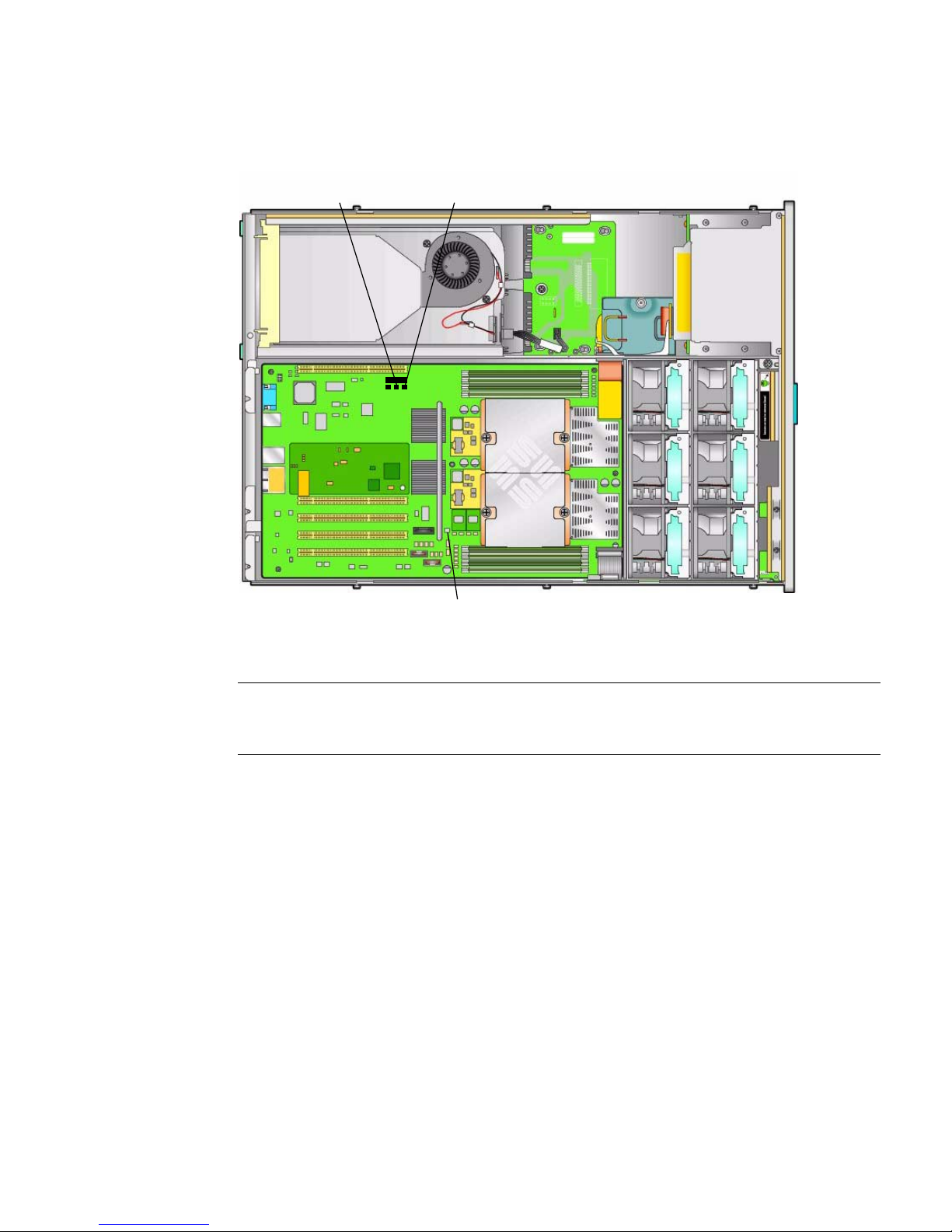
FIGURE 2-8 Location of Jumpers on the Sun Fire X4100/X4200 Motherboard
1
2
3
Figure Legend
1 P4, Password Clear
2 P5, Force Recovery
3 TP51/TP52, CMOS Clear
Chapter 2 Powering On and Configuring BIOS Settings 2-55
Page 84
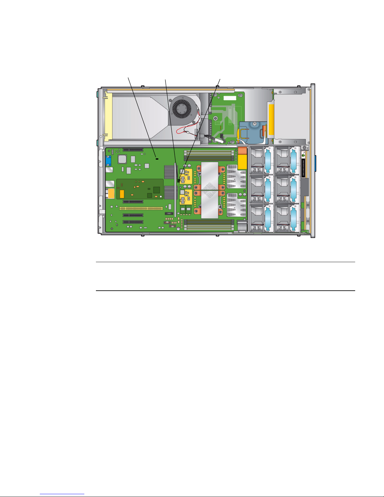
FIGURE 2-9 Location of Jumpers on the Sun Fire X4100 M2/X4200 M2 Motherboard
1
Figure Legend
2
3
1 J9, CMOS Clear
2 J12, Password Clear
3 J13, Force Recovery
2.4.1 Resetting the SP Password
If the ILOM BIOS SP password needs to be reset, do the following to reset the SP and
CMOS passwords:
1. Determine if the ILOM SP first-level booter (U-Boot) is intact. Follow
documented procedures to connect to the SP serial port, apply power to the
system, and observe the initial ILOM boot messages.
See Sun Fire X4500/X4540 Server Installation Guide for details.
■ If no screen output is displayed, stop here. The GRASP board must be replaced.
Refer to Sun Fire X4500/X4540 Server Service Manual for instructions.
■ If screen output is displayed, continue to the next step.
2. Enter the ILOM SP U-Boot command interpreter with xyzzy.
2-56 Sun Fire X4100/X4100 M2 and X4200/X4200 M2 Servers Service Manual • August 2009
Page 85

When the message, Booting linux in 2 seconds... is displayed, during
ILOM initial boot, type xyzzy to enter the U-Boot command interpreter.
Note – The characters typed does not echo. Cutting and pasting the characters
improves the chance of success. You might try cycling power to the system and
entering xyzzy several times.
3. Disable automatic reboot.
Set the uboot environment variable, bootretry, to -1 to temporarily disable
automatic reboot:
set bootretry -1
4. Configure to not save the current configuration:
set preserve_conf no
5. Save your current environment:
saveenv
6. Reboot:
boot
2.5 Using the Force-Recovery Jumper P5 or
J13
The names and locations of this jumper differ between the Sun Fire X4100/X4200 and
the X4100 M2/X4200 M2 servers:
■ In Sun Fire X4100/X4200 servers this jumper is P5. See FIGURE 2-8 for the location.
■ In Sun Fire X4100 M2/X4200 M2 servers this is jumper J13. See FIGURE 2-9 for the
location.
You can use this jumper to force the server to flash a new BIOS in the case of a
system freeze. For example, if the system freezes after an ILOM SP firmware/BIOS
update, use this procedure to force the server to look for the new BIOS.
1. Shut down the server to standby power mode by using a nonconducting pointer
or stylus to press and release the recessed Power button on the front panel. See
Section 2.2, “Powering Off the Server” on page 2-3.
2. Disconnect the power cords from the server.
Chapter 2 Powering On and Configuring BIOS Settings 2-57
Page 86

Caution – Before handling components, attach an ESD wrist strap to the grounding
post that is built into the rear of the chassis (see
page 1-9 for the location). The system’s printed circuit boards and hard disk drives
FIGURE 1-2 on page 1-5 or FIGURE 1-6 on
contain components that are extremely sensitive to static electricity.
3. If the server is in a rack, slide it far enough from the rack so that you can
remove the main cover. If you cannot safely view and access the motherboard,
remove the server from the rack.
4. Remove the main cover from the server. See one of the following:
■ Section 3.5, “Removing the Main Cover of the Sun Fire X4100/X4100 M2
Server” on page 3-6
■ Section 3.8, “Removing the Main Cover of the Sun Fire X4200/X4200 M2
Servers” on page 3-10.
5. Install the shorting jumper across the P5 or J13 header pins.
See
FIGURE 2-8 or FIGURE 2-9 for the jumper location. This jumper’s function is to
instruct the system to force recovery of the latest BIOS at system reboot.
6. Reinstall the main cover to the server.
7. Reconnect power cords to the server.
The server powers up to standby power mode, which is indicated when the
Power/OK LED on the front panel is flashing.
8. Return the server to main power mode by using a nonconducting pointer or
stylus to press and release the recessed Power button on the front panel.
You must fully power on the server to complete the reset. This is because the state
of this jumper cannot be determined without the host CPU running.
9. Repeat steps 1 through 8 to remove the P5 or J13 jumper. (Remove the jumper in
Step 5 rather than inserting it.)
Note – If you do not remove this jumper, the server will force a recovery of the new
BIOS every time that you power cycle the server.
2-58 Sun Fire X4100/X4100 M2 and X4200/X4200 M2 Servers Service Manual • August 2009
Page 87

2.6 Using the Clear CMOS Jumper
TP51/TP52 or J9
The names and locations of this jumper differ between the Sun Fire X4100/X4200 and
the X4100 M2/X4200 M2 servers:
■ In Sun Fire X4100/X4200 servers this is jumper TP51/TP52. See FIGURE 2-8 for the
location.
■ In Sun Fire X4100 M2/X4200 M2 servers this is jumper J9. See FIGURE 2-9 for the
location.
You can use this jumper to clear the server’s CMOS settings in the case of a system
freeze. For example, if the server freezes because of incorrect settings and will not
boot, use this jumper to invalidate the settings and reboot with defaults.
1. Shut down the server to standby power mode by using a nonconducting pointer
or stylus to press and release the recessed Power button on the front panel.
See Section 2.2, “Powering Off the Server” on page 2-3.
2. Disconnect the power cords from the server.
Caution – Before handling components, attach an ESD wrist strap to the grounding
post that is built into the rear of the chassis (see
page 1-9 for the location). PCBs and drivess are extremely sensitive to static electricity.
FIGURE 1-2 on page 1-5 or FIGURE 1-6 on
3. If the server is in a rack, slide it far enough from the rack so that you can
remove the main cover. If you cannot safely view and access the motherboard,
remove the server from the rack.
4. Remove the main cover from the server.
See Section 3.5, “Removing the Main Cover of the Sun Fire X4100/X4100 M2
Server” on page 3-6 or Section 3.8, “Removing the Main Cover of the Sun Fire
X4200/X4200 M2 Servers” on page 3-10.
5. Install the shorting jumper across the TP51/TP52 or J9 header pins.
See
FIGURE 2-8 or FIGURE 2-9 for the jumper location.
6. Wait 10 seconds, then remove the shorting jumper.
This jumper removes battery power from the SouthBridge chipset where the
CMOS settings are stored, thereby removing the CMOS settings.
7. Reinstall the main cover to the server.
Chapter 2 Powering On and Configuring BIOS Settings 2-59
Page 88

8. Reconnect power cords to the server.
The server powers up to standby power mode, which is indicated when the
Power/OK LED on the front panel is flashing.
2.7 Using the Reset and NMI Switches
Caution – Do not use the Reset and NMI switches unless you are instructed to do so
by authorized Service personnel.
The names of these switches differ between the Sun Fire X4100/X4200 and the X4100
M2/X4200 M2 servers:
■ In Sun Fire X4100/X4200 servers, the Reset switch is SW3 and the NMI switch is
SW2. See
■ In Sun Fire X4100 M2/X4200 M2 servers, the Reset switch is SW4 and the NMI
switch is SW3. See
The Reset switch sends a reset order to the CPUs, resetting the main system, but not
the service processor. The button for this switch can be pushed by sticking a paper
clip or similar object through the hole provided on the rear of the chassis (see
FIGURE 2-10).
FIGURE 2-10 for the location.
FIGURE 2-10 for the location.
The Non-Maskable Interrupt (NMI) switch sends an NMI order to the CPUs, which is
used by Field Service for debugging activities at the request of Service personnel. The
button for this switch can be pushed by sticking a paper clip or similar object
through the hole provided on the rear of the chassis (see
2-60 Sun Fire X4100/X4100 M2 and X4200/X4200 M2 Servers Service Manual • August 2009
FIGURE 2-10).
Page 89
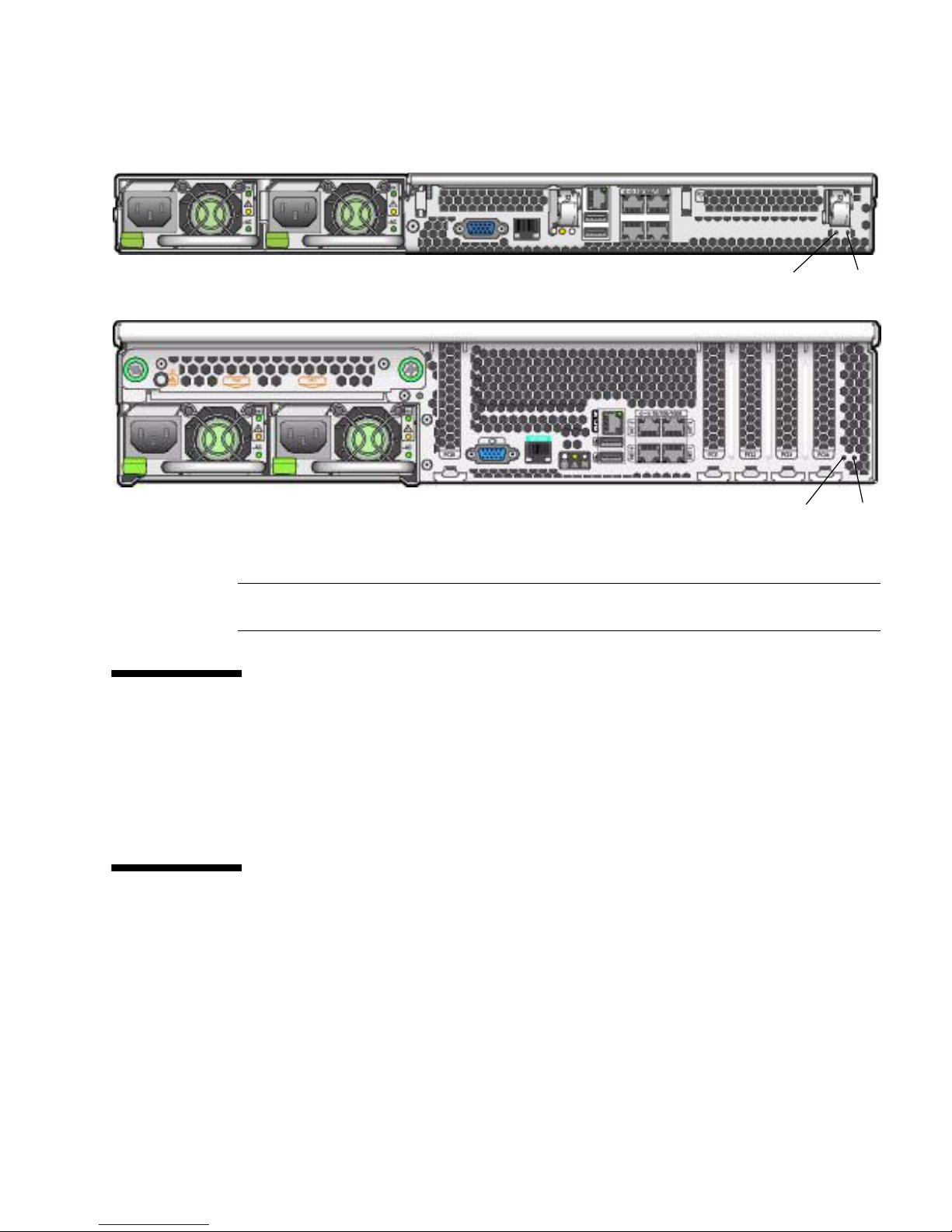
FIGURE 2-10 Server Back Panels
Sun Fire X4100/X4100 M2 Server
Sun Fire X4200/X4200 M2 Server
Figure Legend
1 NMI switch
2 Reset switch
1
1
2
2
2.8 Updating the BIOS
The BIOS is updated whenever you update the ILOM Service Processor firmware.
For instructions on updating the firmware, refer to the Integrated Lights-Out Manager
Administration Guide, 819-1160.
2.9 Power-On Self-Test (POST)
For information about BIOS POST testing, POST codes, POST code checkpoints, and
console redirection, see Appendix B, “BIOS POST Codes” on page B-1.
Chapter 2 Powering On and Configuring BIOS Settings 2-61
Page 90

2-62 Sun Fire X4100/X4100 M2 and X4200/X4200 M2 Servers Service Manual • August 2009
Page 91

CHAPTER
3
Maintaining the Sun Fire Servers
This chapter contains information and procedures for servicing the Sun Fire server
hardware, including component removal and replacement procedures. The sections
include:
■ Section 3.1, “Tools and Supplies Needed” on page 3-2
■ Section 3.2, “Locations of Replaceable Components” on page 3-2
■ Section 3.3, “Servicetool FRU Update Procedure” on page 3-2
■ Section 3.4, “Powering Off the Server” on page 3-4
■ Section 3.5, “Removing the Main Cover of the Sun Fire X4100/X4100 M2 Server”
on page 3-6
■ Section 3.6, “Removing the Front Bezel of the Sun Fire X4100/X4100 M2 Server”
on page 3-7
■ Section 3.7, “Removing the Front Cover of the Sun Fire X4100/X4100 M2 Server”
on page 3-8
■ Section 3.8, “Removing the Main Cover of the Sun Fire X4200/X4200 M2 Servers”
on page 3-10
■ Section 3.9, “Removing the Front Bezel of the Sun Fire X4200/X4200 M2 Servers”
on page 3-11
■ Section 3.10, “Removing the Front Cover of the Sun Fire X4200/X4200 M2 Servers”
on page 3-12
■ Section 3.11, “HT Jumper Configuration for Single-CPU Servers (Sun Fire X4100
M2 and X4200 M2)” on page 3-13
■ Section 3.12, “Replaceable Component Procedures” on page 3-14
Note – All information in this chapter applies to Sun Fire X4100/X4200 and
X4100 M2/X4200 M2 servers, unless otherwise noted in the text.
3-1
Page 92

3.1 Tools and Supplies Needed
The server can be serviced with the following items:
■ No. 2 Phillips screwdriver
■ Adjustable-setting torque driver (5–20 in-lbs)
■ Antistatic wrist strap
■ Nonconducting pointer or stylus, to press the recessed Power button
■ 8-mm nut driver, for motherboard replacement
■ Long-nosed pliers, optional for Graphics Redirect and Service Processor (GRASP)
board removal
3.2 Locations of Replaceable Components
For locations of replaceable Sun Fire X4100/X4100 M2 and Sun Fire X4200/X4200
M2 servers, see “Replaceble Components Overview” on page 1-4.
3.3 Servicetool FRU Update Procedure
Caution – The SunService account is for the use of Sun service representatives only.
Do not use the SunService account unless you are instructed to do so in a procedure
developed by Sun Microsystems.
Note – The servicetool command is supplied on Sun Fire X4100/X4200 servers
that have SP firmware 10708 and later.
1. Use SSH to log into the SunService account. The default password is
changeme.
# ssh <SP IP address> -l sunservice
# <SP IP Address's> password: changeme
3-2 Sun Fire X4100/X4100 M2 and X4200/X4200 M2 Servers Service Manual • August 2009
Page 93

2. At the prompt, enter the servicetool command with options. The options are
defined in the following table.
# servicetool --fru_update=mainboard <Other Options>=<value>
Other Options Value
--fru_product_part_number Write a new part number to the FRU.
--fru_product_serial_number Write a new serial number to the FRU.
--fru_chassis_serial_number Write a new chassis serial number to the FRU.
--fru_asset_tag
Write a new asset tag to the FRU.
3. Watch the output from the command and respond to the confirmation prompts
for continuing the update and rebooting the server.
Servicetool is going to update the mainboard FRU with product and
chassis information collected from the removed mainboard.
The following preconditions must be true for this to work:
* The new mainboard must be installed.
* The service processor must not have been replaced with
the motherboard.
* The service processor firmware must not have been upgraded
prior to the motherboard replacement; do firmware upgrades
after component swaps!
Do you want to continue (y|n)? y
Mainboard FRU configuration has been updated.
You MUST reboot the service processor for to complete this process.
Allow the service processor to fully boot.
DO NOT UNPLUG THE SYSTEM WHILE THE SERVICE PROCESSOR IS BOOTING!
Would you like to reboot the service processor now (y|n)? y
The system is going down NOW!!
Sending SIGTERM to all processes.
Chapter 3 Maintaining the Sun Fire Servers 3-3
Page 94
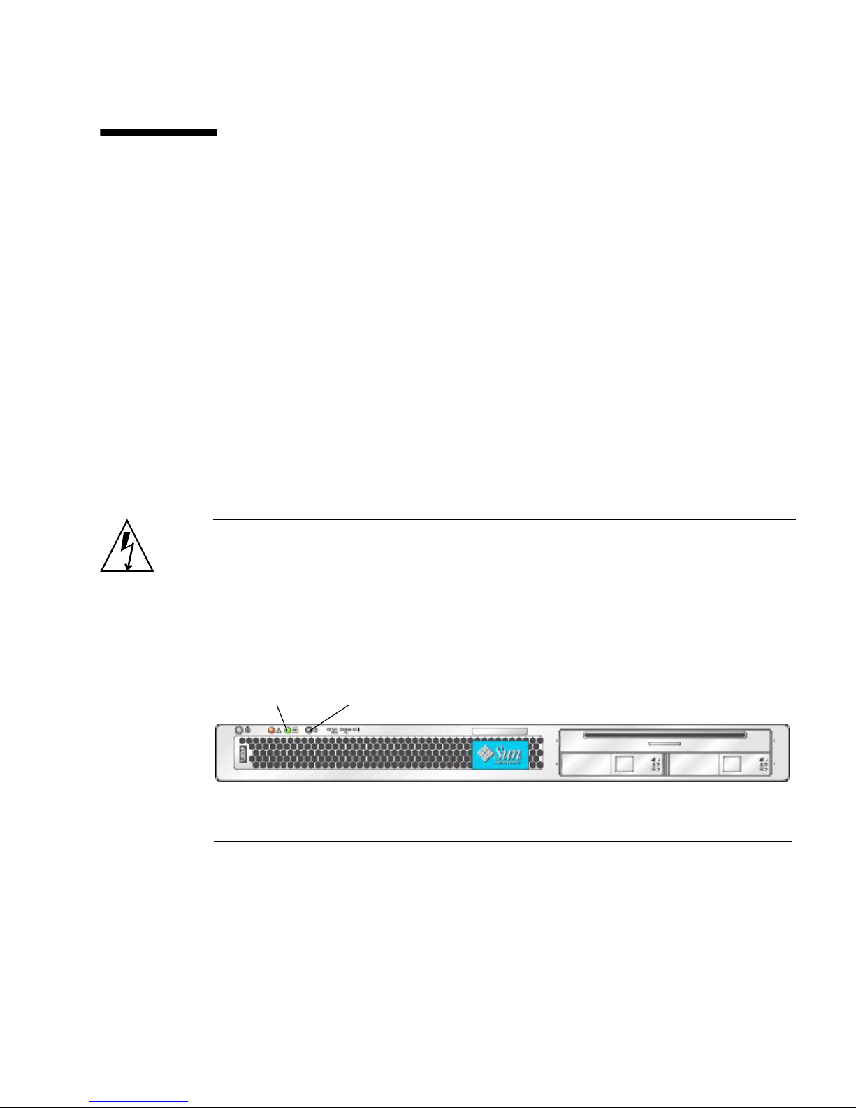
3.4 Powering Off the Server
Use the preparatory procedures in this section when you are referred to them from
the removal and replacement procedures.
1. Choose a method for shutting down the server from main power mode to
standby power mode. See
■ Graceful shutdown: Use a nonconducting pointer or stylus to press and release
the recessed Power button on the front panel. This causes Advanced
Configuration and Power Interface (ACPI) enabled operating systems to
perform an orderly shutdown of the operating system. Servers not running
ACPI-enabled operating systems will shut down to standby power mode
immediately.
■ Emergency shutdown: Press and hold the Power button for four seconds to
force main power off and enter standby power mode.
When main power is off, the Power/OK LED on the front panel will begin
flashing, indicating that the server is in standby power mode.
Caution – When you use the Power button to enter standby power mode, power is
still directed to the GRASP board and power supply fans, which is indicated when
the Power/OK LED is flashing. To completely power off the server, you must
disconnect the power cords from the back panel of the server.
FIGURE 3-1 and FIGURE 3-2.
FIGURE 3-1 Power Button and Power/OK LED Location – Sun Fire X4100/X4100 M2
1
Figure Legend
1 Power/OK LED
2 Power button
3-4 Sun Fire X4100/X4100 M2 and X4200/X4200 M2 Servers Service Manual • August 2009
2
Page 95
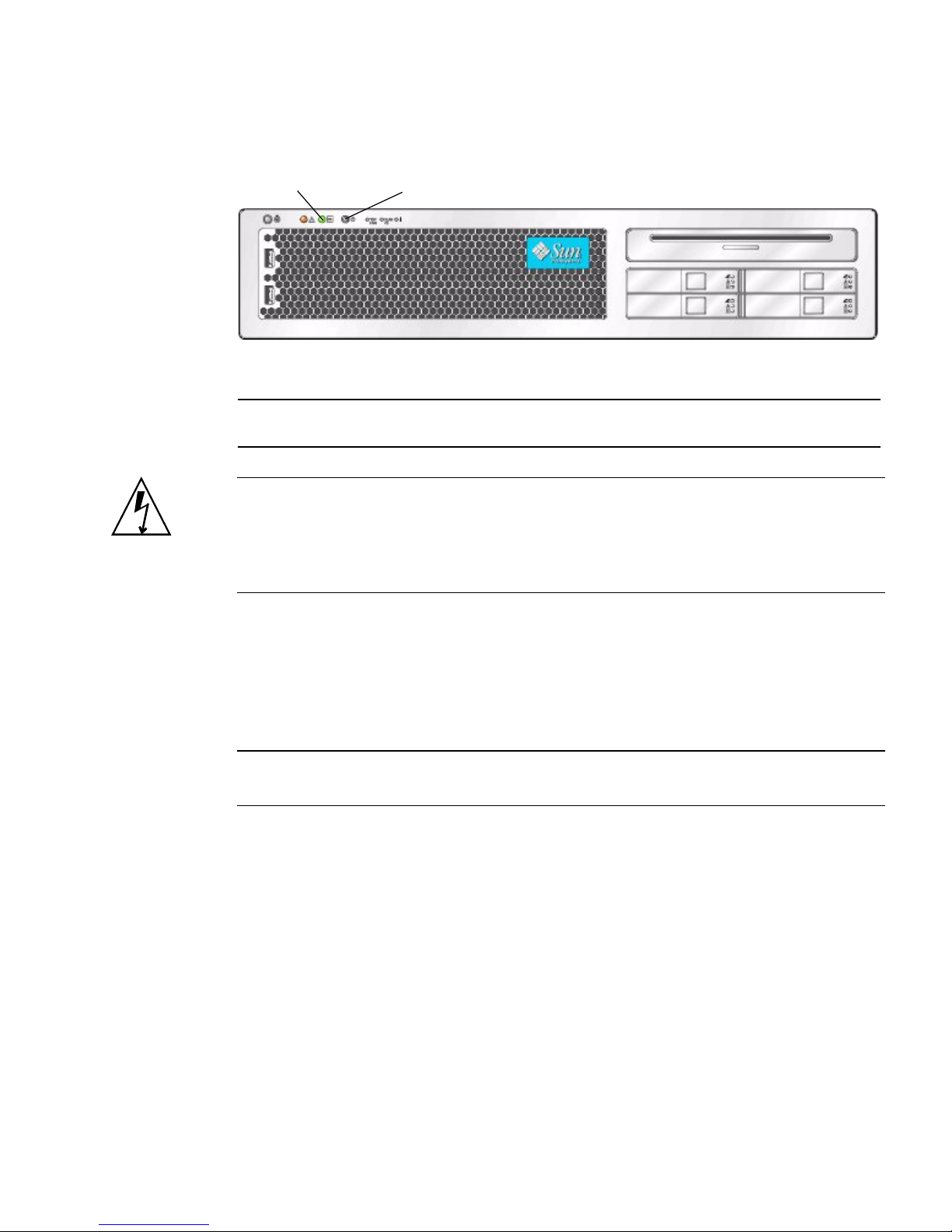
FIGURE 3-2 Power Button and Power/OK LED Location – Sun Fire X4200/X4200 M2
1
Figure Legend
1 Power/OK LED
2 Power button
2
Caution – Before unplugging the power cords from the server or handling internal
components, attach an electrostatic-discharge (ESD) wrist strap to the grounding post
that is built into the rear of the chassis (see
FIGURE 1-2 on page 1-5 for the location). The
system’s printed circuit boards and hard disk drives contain components that are
extremely sensitive to static electricity.
2. Unplug both power cords from the server’s power supplies.
3. Turn off all peripheral devices connected to the system.
4. Label any peripheral cables or telecommunication lines that must be
disconnected in order to remove and replace a specific component.
Note – If your server is a Sun Fire X4200/X4200 M2, skip ahead to Section 3.2 on
page 3-2.
Chapter 3 Maintaining the Sun Fire Servers 3-5
Page 96
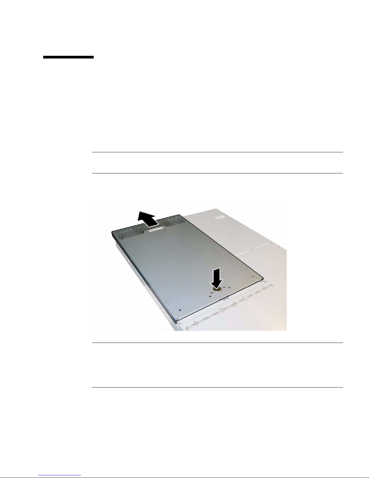
3.5 Removing the Main Cover of the Sun Fire
X4100/X4100 M2 Server
1. Press down on the cover release button and, using the indent for leverage, slide
the main cover toward the rear of the chassis approximately 0.5 inch (12 mm).
See
FIGURE 3-3.
2. Grasp the cover by its rear edge and lift it straight up from the chassis.
Note – When you remove any cover, the intrusion switch that is on the front I/O
board automatically powers down the system to standby power mode.
FIGURE 3-3 Removing the Main Cover
Note – Unclog Heatsinks and Fans – System cooling is affected by dust and
contaminant build-up. Therefore, you should open and check systems approximately
every six months (or more often in dirty operating environments). Check system
heatsinks, fans, and air openings. If necessary, clean systems by carefully brushing,
blowing, or vacuuming contaminants from the system.
3-6 Sun Fire X4100/X4100 M2 and X4200/X4200 M2 Servers Service Manual • August 2009
Page 97
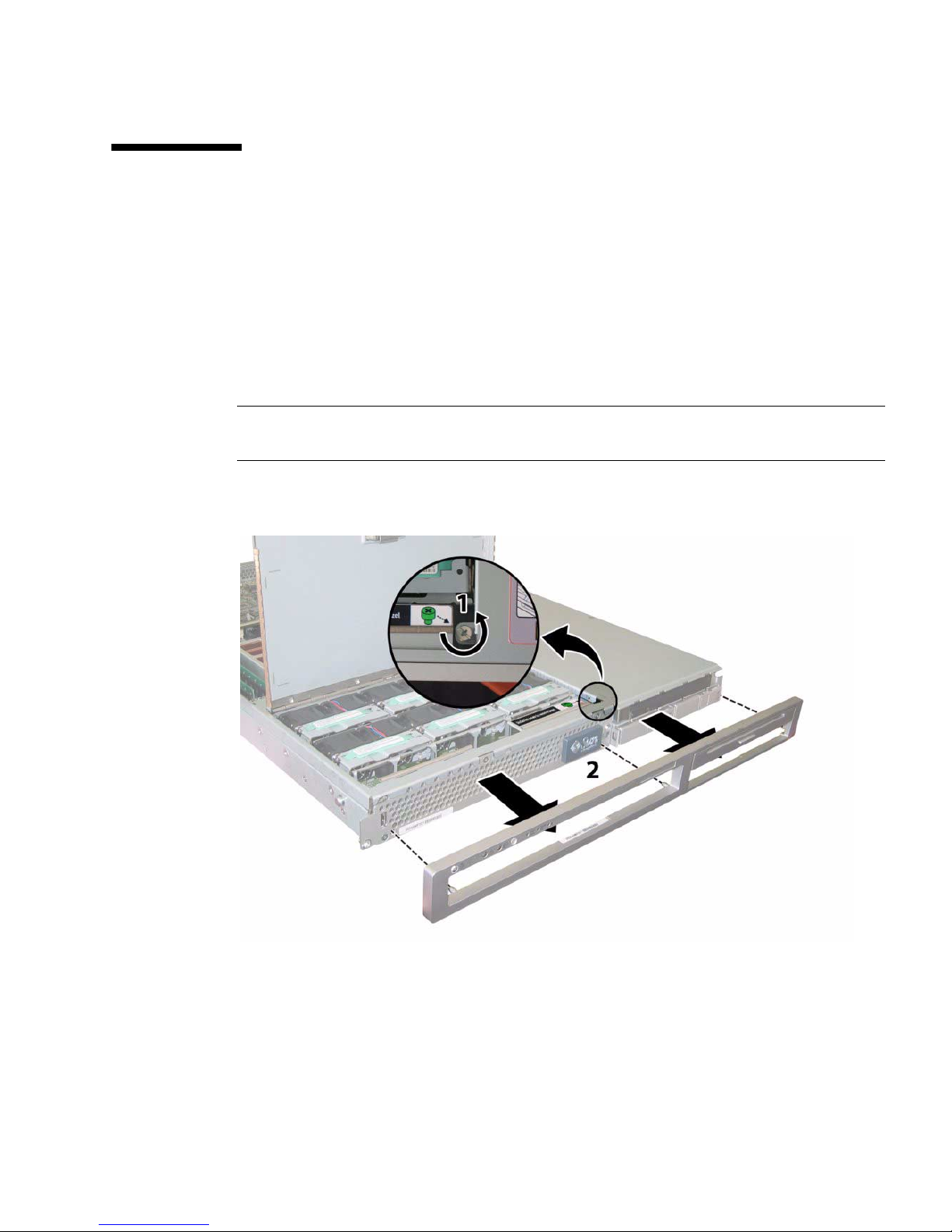
3.6 Removing the Front Bezel of the Sun Fire
X4100/X4100 M2 Server
Remove the bezel from the front of the chassis by following these steps:
1. Open the fan bay door and use a No. 2 Phillips screwdriver to unfasten the
captive screw that locks the bezel in place. See
2. Pull the bezel away from the chassis.
Note – Be careful to avoid bending the bezel by loosening it from the middle and
both end sockets simultaneously.
FIGURE 3-4 Unfastening the Front Bezel Locking Screw
FIGURE 3-4.
Chapter 3 Maintaining the Sun Fire Servers 3-7
Page 98

3.7 Removing the Front Cover of the Sun Fire
X4100/X4100 M2 Server
1. Open the door to the fan bay. See FIGURE 3-5.
2. While holding the fan bay door open, slide the front cover toward the front of
the chassis approximately 0.25 inch (6 mm).
3. Raise the rear edge of the cover first, and then lift it off the chassis.
Note – When you remove any cover, the intrusion switch that is on the front I/O
board automatically powers down the system to standby power mode.
Note – When you replace the front cover, place the front edge on the chassis first,
then set it down into the keyed slots on the chassis sides before sliding it back.
Note – For Sun Fire X4100 servers with the factory-configured option for four hard
disk drives: You must remove the top two hard disk drives before reinstalling the
front cover to provide clearance for the front cover to slide on the chassis. Reinstall
the top two hard disk drives after you reinstall the front cover.
3-8 Sun Fire X4100/X4100 M2 and X4200/X4200 M2 Servers Service Manual • August 2009
Page 99

FIGURE 3-5 Removing the Front Cover
Chapter 3 Maintaining the Sun Fire Servers 3-9
Page 100
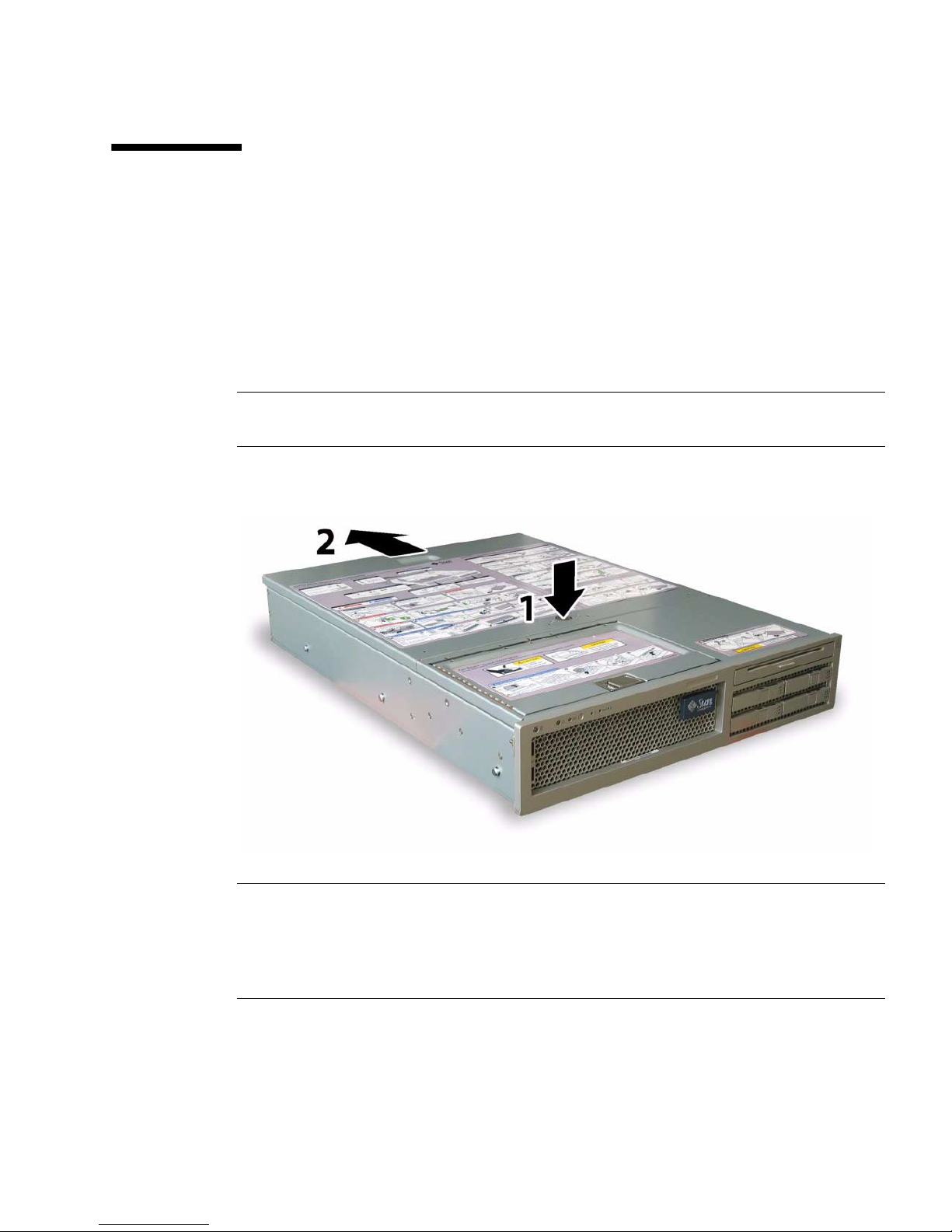
3.8 Removing the Main Cover of the Sun Fire
X4200/X4200 M2 Servers
1. Press down on the cover release and, using the indent for leverage, slide the
main cover toward the rear of the chassis approximately 0.5 inch (12 mm). See
FIGURE 3-6.
2. Grasp the cover by its rear edge and lift it straight up from the chassis.
Note – When you remove any cover, the intrusion switch that is on the front I/O
board automatically powers down the system to standby mode.
FIGURE 3-6 Removing the Main Cover
Note – Unclog Heatsinks and Fans – System cooling is affected by dust and
contaminant build-up. Therefore, you should open and check systems approximately
every six months (or more often in dirty operating environments). Check system
heatsinks, fans, and air openings. If necessary, clean systems by carefully brushing,
blowing, or vacuuming contaminants from the system.
3-10 Sun Fire X4100/X4100 M2 and X4200/X4200 M2 Servers Service Manual • August 2009
 Loading...