

Page 1

Sun Fire X2270 Server
Getting Started Guide
This guide describes the minimum steps you must perform to power on and boot your server for the first time.
Detailed installation information can be found in the Sun Fire X2270 Server Installation Guide, which is available
at the Sun documentation web site:
http://docs.sun.com/app/docs/prod/sf.x2270
Refer to the section “Documentation for This Product” at the end of this document for a complete list of
documentation for this system.
Contents
Carefully unpack all server components from the packing cartons. The following items might be packaged with
your Sun Fire X2270 Server:
■ Power cord packaged separately with country kit
■ Hardware applicable to the system, such as adapters and network cables
■ Sun Fire X2270 Server Base Documentation Kit, including the following:
■ Sun Fire X2270 Server Getting Started Guide
■ License and safety documentation
■ (Optional) Sun Fire X2270 Server Documentation and Media Kit, including the following:
■ Sun Fire X2270 Server Installation Guide
■ Tools & Drivers DVD (includes drivers and additional software), SIA CD/DVD, and SunVTS CD/DVD
■ Additional license and safety documentation
■ (Optional) Rackmount kit containing rack rails and installation instructions
Safety and Compliance Information
Before performing an installation, refer to the following documents for safety information regarding the Sun Fire
X2270 Server:
■ Important Safety Information for Sun Hardware Systems – Printed document included in the ship kit.
■ Sun Fire X2270 Server Safety and Compliance Manual – Available online at the Sun documentation web site.
▼ Install Optional Components
Before installing the server into the rack, you must first install any optional components that you ordered with
the server, such as DIMMs, PCIe cards, and so on. Refer to the Sun Fire X2270 Server Service Manual for the
instructions on installing optional components.
1
Page 2
▼ Mount the System in a Rack
For rackmounting instructions, refer to the instructions included with the rail kit, the service label on the server,
and the online Sun Fire X2270 Server Service Manual.
▼ Connect the Cables
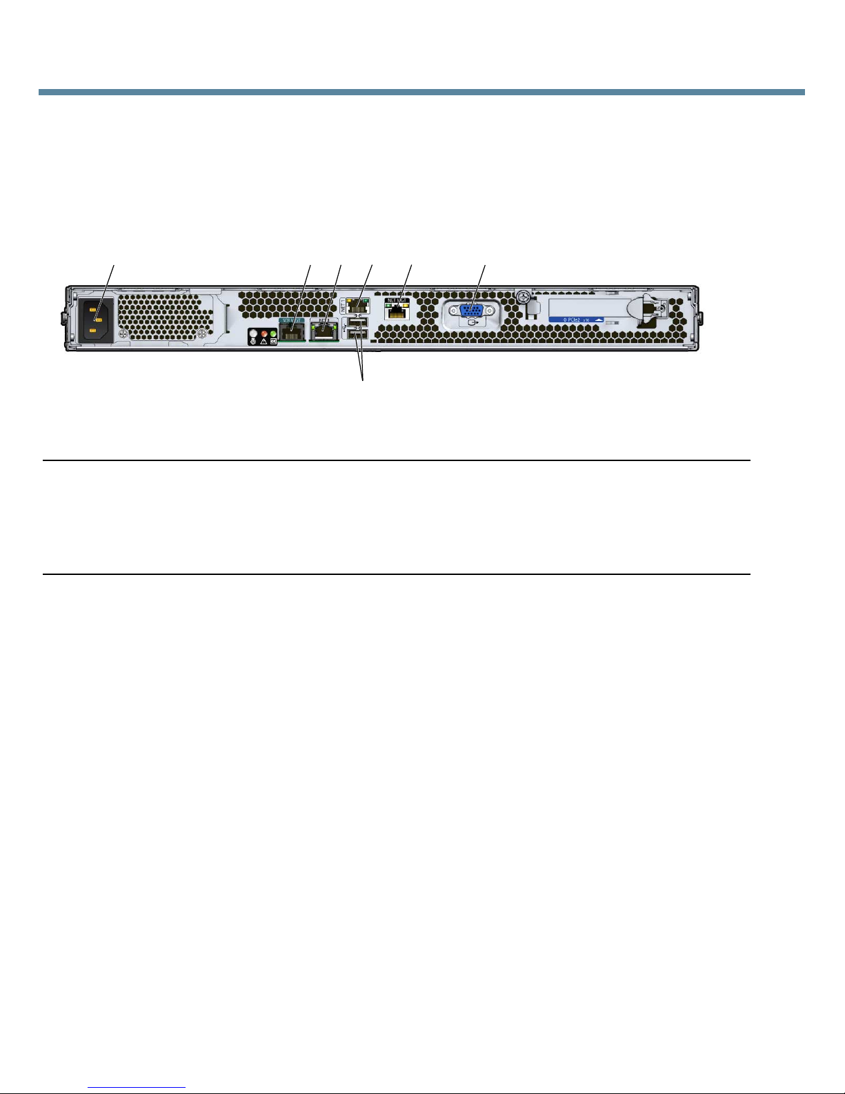
1. Connect a serial cable between the server’s SER MGT port and a terminal device.
1
Figure Legend
1 AC Power connector 5 USB 2.0 ports (2)
2 Serial Management (SER MGT) RS-232 RJ-45 serial port 6 Network Management (NET MGT) Ethernet port (available
3 Gigabit Ethernet port (NET-0) 7 HD15 video connector (available only in systems that
4 Gigabit Ethernet port (NET-1) 8
2
3
5
6
4
only in systems that contain a service processor module)
contain a service processor module)
7
For systems that contain a service processor (SP) module, the connection to the server ’s SER MGT port
provides your initial communication with the SP. The device must be set up to communicate using 9600
baud, 8 bit, no parity, 1 stop bit. A null modem configuration is needed, meaning the transmit and receive
signals are reversed (crossed over) for DTE to DTE communications. You can use the supplied RJ-45
crossover adapter with a standard RJ-45 cable to achieve the null modem configuration.
2. (Optional) Connect an Ethernet cable between the server’s NET MGT port and the network to which
future connections to the SP and host will be made.
After the initial configuration of the system using the SER MGT port, communication with the SP and host is
usually performed through this Ethernet interface.
3. Connect an Ethernet cable between one of the server’s NET ports (NET-0 or NET-1) and the network to
which the server will communicate.
4. Plug the power cord into the power supply.
When power is applied, the SP initializes and the Power/OK LED flashes. After a few minutes, the SP login
prompt appears on the terminal device. Note that the host is not initialized or powered on yet.
For more information on connectivity options, refer to the Sun Fire X2270 Server Installation Guide.
▼ Power On the System
Use this procedure to apply standby power to the service processor (SP) before initial configuration.
2
Page 3
Caution – Do not operate the server without all fans, component heatsinks, air baffles, and the cover
installed. Severe damage to server components can occur if the server is operated without adequate
cooling mechanisms.
Note – Step 1, which describes how to apply standby power for initial SP configuration, is applicable only to
systems that contain an SP module. If your system does not contain an SP, continue with Step 2 to apply main
power to the server.
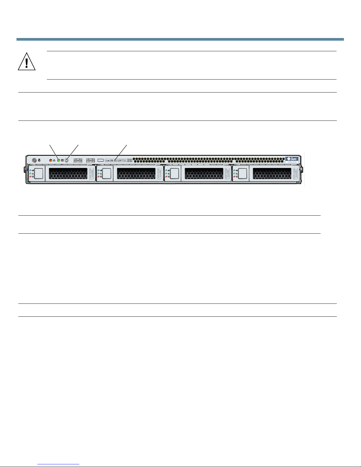
1. Verify that the power cords have been connected and that standby power is on.
1
Figure Legend
1 Green Power/OK LED 3 System Serial Number label
2 Power button 4
2 3
At this point, standby power is supplied only to the service processor and power supply fans. Do not apply
main power to the rest of the server until you are ready to install a platform operating system. In standby
power mode, the Power/OK LED on the front panel flashes.
2. Press and release the Power button on the server front panel to apply main power to the server.
When main power is applied to the full server, the Power/OK LED next to the Power button lights and
remains lit.
Note – The first time the server powers on, the power-on self-test (POST) can take up to 1 minute to complete.
3. Continue with initial software setup tasks, as described in the Sun Fire X2270 Server Installation Guide.
Connection Options
This section describes the tasks for initial setup of the service processor (SP) and Integrated Lights Out Manager
(ILOM) software. Refer to the Sun Fire X2270 Server Installation Guide and the Sun Integrated Lights Out Manager
2.0 User’s Guide for instructions on using ILOM to configure and manage the Sun Fire X2270 Server.
You can connect to the ILOM SP to perform initial setup and configuration in three ways:
■ Connect to ILOM Using a Serial Connection
■ Connect to ILOM Using an Ethernet Connection (DHCP)
■ Connect to ILOM Using an Ethernet Connection (static IP address)
3
Page 4

The method for connecting to ILOM using a serial connection is given in this document. For the remaining
methods, refer to the Sun Fire X2270 Server Installation Guide.
Note – If your server does not contain an SP module or an optional video card, connect the terminal to the server
serial port. Video is routed to the serial port in systems that do not contain an SP or a video card. If your system
does not contain an SP module, skip the steps that require you to log in to and start ILOM.
▼ Connect to ILOM Using a Serial Connection
1. Verify that your terminal, laptop, or terminal server is operational.
2. If not already configured, configure the terminal device or the terminal emulation software running on
your laptop or PC. For information and procedures, see “Connect the Cables” .
3. If not already connected, connect a serial cable from the RJ-45 SER MGT port on the server’s back panel
to the terminal device. For information and procedures, see “Connect the Cables” .
4. Press Enter on the terminal device to establish a connection between the terminal device and the
ILOM SP.
The SP eventually displays a login prompt, such as the following example:
SUNSP003BA84D777 login:
5. Log in to ILOM.
a. Type the default user name: root.
b. Type the default password: changeme.
Once you have successfully logged in, the SP displays its default command prompt:
->
You can now run command-line interface (CLI) commands to configure ILOM for the server ’s user accounts,
network settings, access lists, alerts, and other parameters. For detailed instructions on CLI commands, see
the Sun Integrated Lights Out Manager 2.0 User’s Guide.
Note – You can switch back to the SP CLI from the serial console by entering the Esc ( key sequence.
▼ Register the System
1. Locate the serial number for your system. The serial number is located on the Sun EZ label, the customer
information sheet that came with the system, and on the System Serial Number label located on the front
of the server.
2. Go to the following web site to register your system:
http://www.sun.com/service/warranty/index.xml#reg
▼ Set Up the Platform Operating System, Driver Software, and Firmware
After configuring the ILOM SP with network settings, you can configure an optional preinstalled operating
system (OS) or install a supported Solaris™, Linux, or Windows platform OS and drivers. For more information
and instructions, see the following documents.
4
Page 5

Note – Sun highly recommends that you use the Sun Installation Assistant (SIA) software when installing an OS
other than Solaris. SIA will help locate and install all necessary OS components automatically.
Operating System Read this document: For additional information, go to:
Preinstalled Solaris Sun Fire X2270 Server Installation Guide http://www.sun.com/
software/preinstall
Solaris Sun Fire X2270 Server OS Installation Guide http://www.sun.com/servers/
Linux Sun Fire X2270 Server OS Installation Guide
Sun Installation Assistant for Windows and Linux User’s Guide http://www.sun.com/
Windows Sun Installation Assistant for Windows and Linux User’s Guide
Sun Fire X2270 Server Windows OS Installation Guide http://www.sun.com/servers/
Note – For information about supported operating systems, patches, and the latest firmware, refer to the Sun Fire X2270
Server Product Notes. Information on the latest firmware is also available at: http://www.sun.com/server/x64/x2270/
downloads.jsp.
x64/x2270/os.jsp
systemmanagement/sia.jsp
x64/x2270/os.jsp
▼ Upgrade Firmware
For instructions on upgrading firmware on your system, refer to the Sun Fire X2270 Server Service Manual.
Documentation for This Product
The following table lists the documentation in the approximate order of the tasks that you might perform when
installing a new system. Review the tasks on the left, then refer to the corresponding documentation on the
right. You can find the most up-to-date versions of all the documents at the Sun documentation web site:
http://docs.sun.com/app/docs/prod/sf.x2270
For translated versions of the documentation, go to the http://docs.sun.com web site, then select your
language to get the documentation set in your language.
Task Document Type Part Number
Review the safety information. Safety and Compliance Manual (820-5605)
Important Safety Information for Sun
Hardware Systems
Review any known issues and workarounds. Product Notes (820-5608)
Install rack hardware.
Cable and power on server.
Connect to the service processor and determine network
settings.
Configure the optional preinstalled Solaris OS.
Installation Guide (820-5604)
(816-7190)
5
Page 6

Task Document Type Part Number
Install supported operating systems.
Reinstall Solaris, or install Linux or Windows Server.
Operating System Installation Guide (820-5606)
Windows Operating System Installation
(820-7143)
Guide
Sun Installation Assistant for Windows
(820-3357)
and Linux User ’s Guide
Manage server accounts, monitor alerts, set remote access
and redirection, and view component status and event logs.
Sun Integrated Lights Out Manager 2.0
User ’s Guide
Sun Integrated Lights Out Manager 2.0
(820-1188)
(820-5609)
Supplement for Sun Fire X2270 Server
Customize BIOS settings and RAID settings.
Service Manual (820-5607)
Remove and replace hardware components.
Troubleshoot and isolate server problems.
Review system specifications and hardware reference
material.
Diagnose system issues. Diagnostics Guide (820-6750)
Sun Contact Information
Topic URL
Technical support
Submitting comments about this
document
http://www.sun.com/service/contacting
http://www.sun.com/hwdocs/feedback
Please include the title and part number of your document with your feedback:
Sun Fire X2270 Server Getting Started Guide, part number 820-5610-11
Patch and firmware updates http://www.sun.com/support/index.jsp
Copyright 2008 Sun Microsystems, Inc. All rights reserved.
Copyright 2008 Sun Microsystems, Inc. Tous droits réservés.
Sun Microsystems, Inc.
www.sun.com
Part No. 820-5610-11, Rev. A
April 2009
6
 Loading...