

Page 1

Sun Microsystems, Inc.
www.sun.com
Submit comments about this document at: http://www.sun.com/hwdocs/feedback
Sun Fire™X2250 Server
Installation Guide
Part No. 820-4591-10, Rev. A
May 2008
Page 2

Please
Recycle
Copyright ©2008 Sun Microsystems, Inc., 4150 Network Circle,Santa Clara, California 95054, U.S.A.All rights reserved.
Sun Microsystems, Inc.has intellectual property rights relating to technologyembodied in the product that is describedin this document. In
particular,and without limitation, these intellectualproperty rightsmay include one or more ofthe U.S. patents listed at
http://www.sun.com/patents andone or more additional patents or pendingpatent applications in the U.S.and in other countries.
This distributionmay include materials developed bythird parties.
Parts ofthe product may be derived from BerkeleyBSD systems, licensed from the University ofCalifornia. UNIX is a registered trademark in
the U.S.and in other countries, exclusivelylicensed through X/Open Company, Ltd.
Sun, SunMicrosystems, the Sun logo, Java, Solaris, Sun Fire, Sun Solve, Sun Service,and SunVTS are trademarks or registered trademarks of
Sun Microsystems, Inc.in the U.S. and othercountries.
Microsoft is a trademarkor registered trademark of Microsoft Corporation or itssubsidiaries inthe United States and Other countries. Windows
is atrademark or registered trademark of Microsoft Corporation or itssubsidiaries in the United Statesand Other countries. Intel isa trademark
or registered trademark of Intel Corporation or its subsidiaries in the United States and other countries. The Adobe logo isa registered
trademark ofAdobe Systems, Incorporated.
Use ofany spare or replacement CPUs is limitedto repairor one-for-one replacement of CPUs in products exportedin compliance with U.S.
export laws.Use of CPUs as product upgradesunless authorized by the U.S.Government is strictly prohibited.
DOCUMENTATION IS PROVIDED "AS IS" AND ALL EXPRESS OR IMPLIED CONDITIONS, REPRESENTATIONS AND WARRANTIES,
INCLUDING ANY IMPLIED WARRANTY OFMERCHANTABILITY,FITNESS FOR A PARTICULAR PURPOSE OR NON-INFRINGEMENT,
ARE DISCLAIMED, EXCEPT TO THE EXTENT THAT SUCH DISCLAIMERS ARE HELD TO BE LEGALLY INVALID.
Copyright ©2008 Sun Microsystems, Inc., 4150 Network Circle,Santa Clara, California 95054, Etats-Unis.Tous droitsréservés.
Sun Microsystems, Inc.détient les droits de propriété intellectuels relatifs àla technologie incorporée dans le produit quiest décrit dans ce
document. Enparticulier, et ce sanslimitation, ces droits de propriété intellectuelle peuvent inclure unou plus des brevets américains listés à
l'adresse http://www.sun.com/patents et un ou les brevets supplémentaires ou les applications debrevet en attente aux Etats - Unis et dans les
autres pays.
Cette distributionpeut comprendredes composants développés par destierces parties.
Des partiesde ce produit pourront être dérivées des systèmes BerkeleyBSD licenciés par l'Université deCalifornie. UNIX est une marque
déposée auxEtats-Unis et dans d'autres pays et licenciée exclusivement par X/Open Company, Ltd.
Sun, SunMicrosystems, le logo Sun, Java, Solaris, Sun Fire, Sun Solve, Sun Service,et SunVTS sont des marques de fabriqueou des marques
déposées deSun Microsystems, Inc. aux Etats-Unis et dans d'autres pays.
Microsoft sont est marquesde fabrique ou des marques déposéesde MicrosoftCorporation ou de sa filialeaux Etats-Unis et dans d’autres pays.
Windows est une marque de fabriqueou une marques déposée de Microsoft Corporation ou de sa filiale aux Etats-Unis etdans d’autres pays.
Intel estune marque déposée ou marque déposée d'IntelCorporation ou ses filiales auxEtats-Unis et à d'autres pays. Le logoAdobe est une
marque déposée de Adobe Systems, Incorporated.
L'utilisation depieces detachees ou d'unites centralesde remplacement est limitee aux reparations oua l'echange standard d'unites centrales
pour lesproduits exportes, conformement a la legislation americaine en matiere d'exportation. Sauf autorisationpar les autorites des EtatsUnis, l'utilisationd'unites centrales pour proceder a des mises a jour de produits estrigoureusement interdite.
LA DOCUMENTATION EST FOURNIE "EN L'ETAT" ET TOUTES AUTRES CONDITIONS, DECLARATIONS ET GARANTIES EXPRESSES
OU TACITES SONT FORMELLEMENT EXCLUES, DANS LAMESURE AUTORISEEPARLA LOI APPLICABLE, Y COMPRISNOTAMMENT
TOUTE GARANTIE IMPLICITE RELATIVE A LA QUALITE MARCHANDE, A L'APTITUDE A UNE UTILISATION PARTICULIERE OU A
L'ABSENCE DE CONTREFACON.
Page 3

iii
Contents
Preface v
1. Setting Up the Sun Fire X2250 Server Hardware 1
Safety and Compliance Information 1
Planning the Installation Process 2
Package Contents Inventory 3
Installing the Server Into a Rack With Optional Slide Rails 3
Connecting the Cables 4
▼ To Connect the Cables 4
Powering On and Off the Server 5
▼ To Apply Standby Power for Initial Service Processor Configuration 6
▼ To Power On Main Power Mode 7
▼ To Power Off Main Power Mode 7
Setup Troubleshooting and Support 8
Troubleshooting the Sun Fire X2250 Server Setup 8
Contacting Support 10
2. Setting Up the Sun Fire X2250 Server Software 13
Introduction to the Integrated Lights Out Manager 14
Connecting to the ILOM Service Processor 16
Page 4

iv Sun Fire X2250 Server Installation Guide • May 2008
▼ To Connect to ILOM Using a Serial Connection 16
Connecting to ILOM Using an Ethernet Connection 18
Configuring ILOM Using Dynamic Ethernet Settings 18
▼ To Configure ILOM Ethernet Settings Using DHCP 18
Configuring ILOM Using Static Ethernet Settings 21
▼ To Configure Static IP Addresses Using the Web Interface 21
▼ To Configure Static IP Addresses Using the CLI 22
▼ To Configure Static IP Addresses Using the BIOS Setup Utility 23
Setting Up Platform Operating System and Driver Software 24
Installing Other Operating Systems and Drivers 24
3. Configuring the Preinstalled Solaris 10 Operating System 25
Before You Begin 25
Installation Worksheet 26
Selecting Your Console Output 29
Configuring the Preinstalled Solaris 10 Operating System 30
▼ To Connect to the Server Using the Service Processor’s IP Address 31
▼ To Connect to the Server Using a Terminal Program 32
Solaris 10 Operating System User Information 33
Accessing Solaris 10 OS User Documentation 33
Downloading Solaris 10 OS Software 34
Solaris 10 OS Training 34
Page 5

v
Preface
This Sun Fire X2250 Server Installation Guide contains procedures for installing the
server into a rack, connecting to the service processor, and configuring the
preinstalled Solaris™ Operating System.
Using UNIX Commands
This document might not contain information about basic UNIX®commands and
procedures such as shutting down the system, booting the system, and configuring
devices. Refer to the following for this information:
■ Software documentation that you received with your system
■ Solaris™ Operating System documentation, which is at:
http://docs.sun.com
Page 6

vi Sun Fire X2250 Server Installation Guide • May 2008
Shell Prompts
Typographic Conventions
Shell Prompt
C shell machine-name%
C shell superuser machine-name#
Bourne shell and Korn shell $
Bourne shell and Korn shell superuser #
Typeface
*
* The settings on your browser might differ from these settings.
Meaning Examples
AaBbCc123 The names of commands, files,
and directories; on-screen
computer output
Edit your.login file.
Use ls -a to list all files.
% You have mail.
AaBbCc123 What you type, when contrasted
with on-screen computer output
%
su
Password:
AaBbCc123 Book titles, new words or terms,
words to be emphasized.
Replace command-line variables
with real names or values.
Read Chapter 6 in the User’s Guide.
These are called class options.
You must be superuser to do this.
To delete a file, type rm filename.
Page 7

Preface vii
Related Documentation
The documents listed in the following table are available online at:
http://docs.sun.com
At that site, search for the Sun Fire™ X2250 Server.
Note – The last two digits of the documentation part number identify the latest
version of the product documentation that is available for download (or viewing
online). For example: 820-xxxx-XX.
Title Content Part Number Format
Sun Fire X2250 Server Product
Notes
Late-breaking information
about the server.
820-4594 PDF
HTML
Sun Fire X2250 Server Getting
Started Guide
Basic installation information
for setting up the server.
820-4590 PDF
Print
Sun Fire X2250 Server
Installation Guide
Detailed installation
information for setting up the
server.
820-4591 PDF
HTML
Print option
Sun Fire X2250 Server
Operating System Installation
Guide
Installation instructions for
the Solaris, Linux, and
Windows Server operating
systems.
820-4592 PDF
HTML
Sun Installation Assistant for
Windows and Linux User’s
Guide
Installation instructions using
the Sun Installation Assistant
for the Linux and Windows
Server operating systems.
820-3357 PDF
HTML
Sun Fire X2250 Server Service
Manual
Information and procedures
for maintaining and
upgrading the server.
820-4593 PDF
HTML
Sun Integrated Lights Out
Manager 2.0 User’s Guide
ILOM features and tasks that
are common to servers and
server modules that support
ILOM.
820-1188 PDF
HTML
Page 8

viii Sun Fire X2250 Server Installation Guide • May 2008
Support and Training
Sun Integrated Lights Out
Manager Supplement for Sun
Fire X2250 Server
ILOM information that is
specific to the server.
820-4596 PDF
HTML
Sun Fire X2250 Server Safety
and Compliance Manual
Hardware safety and
compliance information for
the server.
820-4595 PDF
Important Safety Information
for Sun Hardware Systems
Multilingual hardware safety
and compliance information
for all Sun hardware systems.
816-7190 Print
Sun Function URL
Support http://www.sun.com/support/
Training http://www.sun.com/training/
Title Content Part Number Format
Page 9

Preface ix
Product Updates
For product updates that you can download for the Sun Fire X2250 server, visit the
following web site:
http://www.sun.com/download/
Find the Hardware Drivers section and click x64 Servers & Workstations. The Sun
Fire X2250 server site contains updates for firmware and drivers, as well as CD-ROM
.iso images.
Third-Party Web Sites
Sun is not responsible for the availability of third-party web sites mentioned in this
document. Sun does not endorse and is not responsible or liable for any content,
advertising, products, or other materials that are available on or through such sites
or resources. Sun will not be responsible or liable for any actual or alleged damage
or loss caused by or in connection with the use of or reliance on any such content,
goods, or services that are available on or through such sites or resources.
Sun Welcomes Your Comments
Sun is interested in improving its documentation and welcomes your comments and
suggestions. You can submit your comments by going to:
http://www.sun.com/hwdocs/feedback
Include the title and part number of your document with your feedback:
Sun Fire X2250 Server Installation Guide, part number 820-4591-10
Page 10

x Sun Fire X2250 Server Installation Guide • May 2008
Page 11

1
CHAPTER
1
Setting Up the Sun Fire X2250 Server
Hardware
This chapter describes how to set up the Sun Fire X2250 server hardware. It includes
the following topics:
■ “Safety and Compliance Information” on page 1
■ “Planning the Installation Process” on page 2
■ “Package Contents Inventory” on page 3
■ “Installing the Server Into a Rack With Optional Slide Rails” on page 3
■ “Connecting the Cables” on page 4
■ “Powering On and Off the Server” on page 5
■ “Setup Troubleshooting and Support” on page 8
Safety and Compliance Information
Refer to the following documents for safety information regarding the Sun Fire
X2250 server:
■ Important Safety Information for Sun Hardware Systems, 816-7190: printed document
included in the ship kit.
■ Sun Fire X2250 Server Safety and Compliance Manual (820-4595): available online by
navigating to the Sun Fire X2250 server document page from the following URL:
http://docs.sun.com/
Page 12
2 Sun Fire X2250 Server Installation Guide • May 2008
Planning the Installation Process
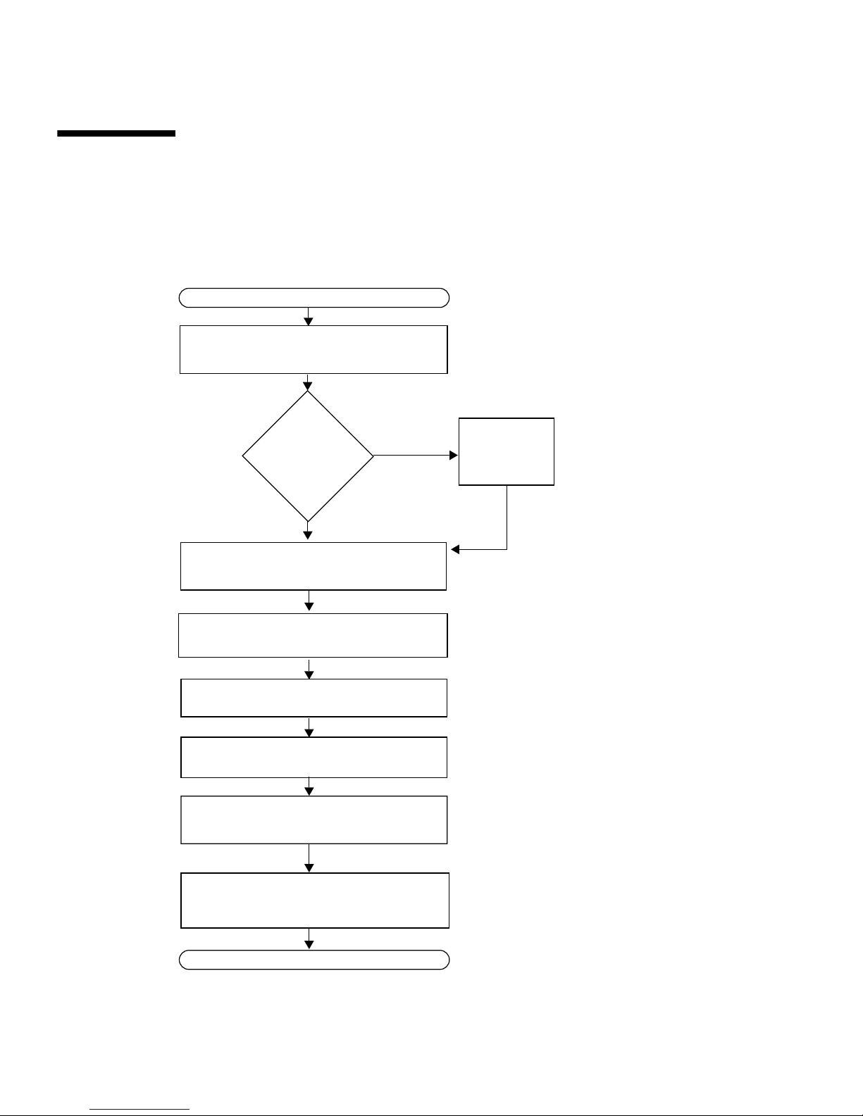
Use the flowchart in FIGURE 1-1 to assist you with the server installation process.
FIGURE 1-1 Sun Fire X2250 Server Installation Process
Unpack the server and familiarize yourself
with the server features.
Connect the server and external device
cables.
Power on the server.
If necessary, install the supplemental drivers
from the Sun Fire X2250 Server Tools and
Drivers CD.
READY TO USE
START
Install the operating system or configure the
preinstalled operating system.
Install
additional
components?
Install
additional
components.
Yes
No
See “Package Contents Inventory” on page 3.
To install additional
components, see the Sun Fire
X2250 Server Service Manual or
the component documentation.
See “Connecting the Cables” on page 4.
See “Powering On and Off the Server” on page 5.
See “Setting Up Platform Operating System
and Driver Software” on page 24 or
“Configuring the Preinstalled Solaris 10
Operating System” on page 25.
See “If you do not plan to use an operating
system (OS) that is preinstalled on your Sun
(Optional) Mount the server in a rack.
See the service label on the top cover of the
server or the Sun Fire X2250 Server Service
Manual.
Set up the service processor.
See “Connecting to the ILOM Service
Processor” on page 16.
Page 13

Chapter 1 Setting Up the Sun Fire X2250 Server Hardware 3
Package Contents Inventory
Carefully unpack all server components from the packing cartons. The following
items should be packaged with the Sun Fire X2250 server:
■ Sun Fire X2250 server
■ Sun Fire X2250 server accessory kit (optional), including the following:
■ Sun Fire X2250 Server Installation Guide (820-4591)
■ Additional license, safety, and registration documentation
■ Sun Fire X2250 Server Tools & Drivers CD (includes drivers and additional
software)
■ Optional rackmount and/or cable management kit
Installing the Server Into a Rack With
Optional Slide Rails
The service label on the top cover of the Sun Fire X2250 server contains instructions
for installing your server into a four-post rack using the orderable slide-rail and
cable management arm options. Detailed instructions can also be found online in the
Sun Fire X2250 Server Service Manual (820-4593) at the following URL:
http://docs.sun.com
The slide rails for the Sun Fire X2250 server are compatible with a wide range of
equipment racks that meet the following standards:
■ Four-post structure (mounting at both front and rear). Two-post racks are not
compatible.
■ Rack horizontal opening and unit vertical pitch conforming to ANSI/EIA 310-D-
1992 or IEC 60927 standards.
■ Distance between front and rear mounting planes of 610 mm and 915 mm
(24 inches to 36 inches).
■ Clearance depth (to front cabinet door) in front of front rack mounting plane at
least 25.4 mm (1 inch).
■ Clearance depth (to rear cabinet door) behind front rack mounting plane at least
800 mm (31.5 inches) with the cable management arm, or 700 mm (27.5 inches),
without the cable management arm.
Page 14
4 Sun Fire X2250 Server Installation Guide • May 2008
■ Clearance width (between structural supports and cable troughs) between front
and rear mounting planes at least 456 mm (18 inches).
Caution – Always load equipment into a rack from the bottom up so that the rack
will not become top-heavy and tip over. Deploy your rack’s anti-tilt bar to prevent
the rack from tipping during equipment installation.
Caution – Ensure that the temperature in the rack does not exceed the server’s
maximum ambient rated temperatures. Consider the total airflow requirements of all
equipment installed in the rack, to ensure that the equipment is operated within its
specified temperature range.
Connecting the Cables
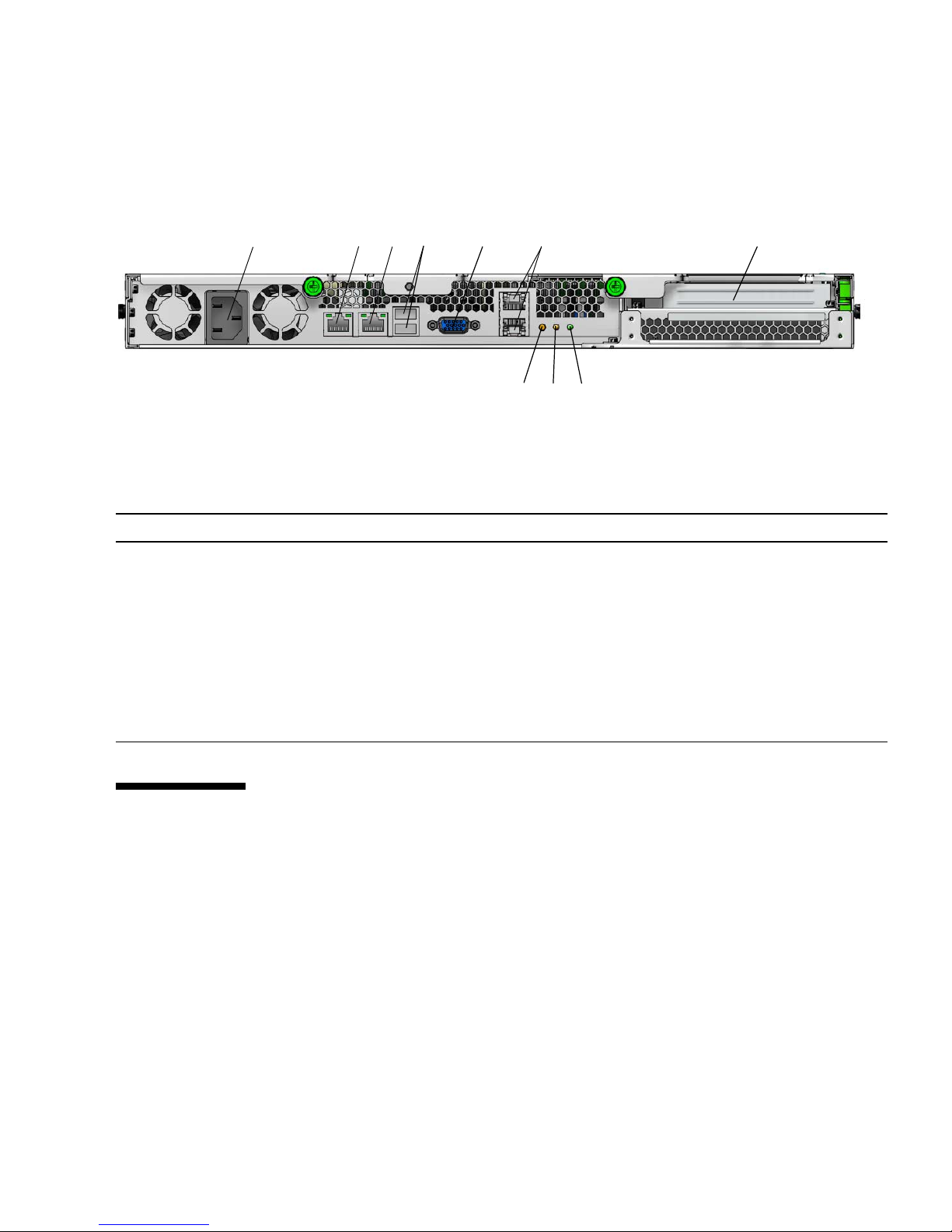
See FIGURE 1-2 and TABLE 1-1 for the locations of the connectors.
▼ To Connect the Cables
Connect the server and external devices as follows:
1. Connect a serial null modem cable to the serial port.
The default serial port speed is 9600 baud with no flow control.
2. Connect Ethernet cables to the RJ-45 LAN Gigabit Ethernet connectors as
needed (see
FIGURE 1-2).
Note the following guidelines regarding the Ethernet (LAN) ports:
■ The Network Management (NET MGT) Ethernet port or the Serial Management /
RS-232-F RJ-45 serial port can be used for server management and network access.
See “Setting Up the Sun Fire X2250 Server Software” on page 13 for additional
information about setting up the service processor for remote system
management.
■ The two Gigabit Ethernet ports (LAN-0 and LAN-1) are the primary network
interface controllers (NICs) and should be used for network installation of the
operating system and drivers.
Page 15
Chapter 1 Setting Up the Sun Fire X2250 Server Hardware 5
3. Connect any additional external devices to the server’s other connectors.
FIGURE 1-2 Back Panel
Powering On and Off the Server
You only need to apply standby power to the server at this point so that you can
perform initial configuration of the service processor. Procedures for powering on to
main power mode and for shutting down from main power mode are also included in
this section, for your reference.
TABLE 1-1 Back Panel
Label Connector/Slot Label Connector/Slot
1 AC Power connector 6 Gigabit Ethernet ports (LAN-0 top, LAN-1
bottom)
2 Network Management (NET MGT) Ethernet
port
7 Locate LED
3 Serial Management (SER MGT) / RS-232-F
RJ-45 serial port
8 Fault LED
4 USB 2.0 connectors (2) 9 Power LED
5 On-board HD15 video connector 10 PCI Express slot
2
10
9
6
34 5
7
8
1
Page 16
6 Sun Fire X2250 Server Installation Guide • May 2008
▼ To Apply Standby Power for Initial Service
Processor Configuration
Use this procedure to apply standby power to the service processor (SP) before initial
configuration.
Caution – Do not operate the server without all fans, component heatsinks, air baffles,
and the cover installed. Severe damage to server components can occur if
operated
without adequate cooling mechanisms.
1. Connect a grounded AC power cord to the AC power connector on the back
panel of the server and to a grounded AC power outlet.
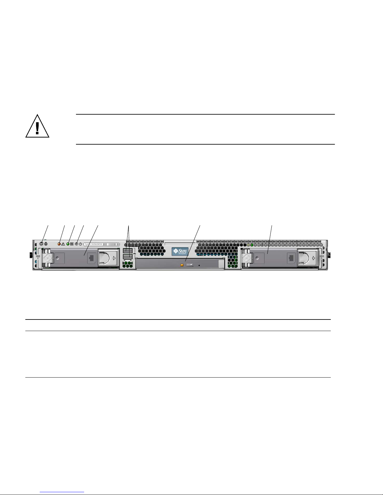
In standby power mode, the Power/OK LED on the front panel flashes,
indicating
that the SP is receiving power. See FIGURE 1-3 and TABLE 1-2.
FIGURE 1-3 Front Panel
2. Continue with initial software setup tasks, as described in Chapter 2.
TABLE 1-2 Front Panel
Label Button/LED/Port Label Button/LED/Port
1 Locate LED 5 Optional SATA hard disk drive 0
2 Fault LED 6 USB 2.0 connectors (2)
3 Power/OK LED 7 Optional DVD drive
4 Power button 8 Optional SATA hard disk drive 1
21345 6 7 8
Page 17

Chapter 1 Setting Up the Sun Fire X2250 Server Hardware 7
Note – At this point, standby power is supplied only to the service processor and power
supply fans. You can proceed to Chapter 2 of this guide to begin initial configuration. Do
not apply main power to the rest of the server until you are ready to install a platform
operating system.
▼ To Power On Main Power Mode
To power on main power for all server components:
1. Verify that the power cord has been connected and that standby power is on.
In standby power mode, the Power/OK LED on the front panel flashes. See
FIGURE 1-3.
2. Use a non-metallic stylus to press and release the recessed Power button on the
server front panel.
When main power is applied to the full server, the Power/OK LED next to the
Power button lights and remains lit.
Note – The first time the server powers on, the power-on self-test (POST) can take
up to a minute to complete.
▼ To Power Off Main Power Mode
To power off the server from main power mode, use one of the following two
methods:
■ Graceful shutdown: Use a non-metallic stylus to press and release the Power
button on the front panel. This causes Advanced Configuration and Power
Interface (ACPI) enabled operating systems to perform an orderly shutdown of
the operating system. Servers not running ACPI-enabled operating systems will
shut down to standby power mode immediately.
■ Emergency shutdown: Press and hold the Power button for four seconds to force
main power off and enter standby power mode. When the main power is off, the
Power/OK LED on the front panel will begin flashing, indicating that the server
is in standby power mode.
Caution – To completely power off the server, you must disconnect the AC power cords
from the back panel of the server.
Page 18

8 Sun Fire X2250 Server Installation Guide • May 2008
Setup Troubleshooting and Support
This section contains information to help you troubleshoot minor server problems.
It includes the following topics:
■ “Troubleshooting the Sun Fire X2250 Server Setup” on page 8.
■ “Contacting Support” on page 10
Troubleshooting the Sun Fire X2250 Server Setup
If you experience problems while setting up your server, refer to the troubleshooting
information in
TABLE 1-3.
TABLE 1-3 Troubleshooting Procedures
Problem Possible Solution
Server powers on, but
the monitor does not.
• Is the Power button for the monitor turned on?
• Is the monitor power cord connected to a wall outlet?
• Does the wall outlet have power? Test by plugging in another
device.
CD or DVD does not
eject from the media
tray when you press
the Eject button.
• Move the mouse or press any key on the keyboard. The drive
might be in low power mode.
• Use the utility software installed on your server to eject the CD.
• Ensure that the media in the device is not in use and is not
mounted by the operating system.
No video is displayed
on the monitor
screen.
• Is the monitor cable attached to the video connector?
• Does the monitor work when connected to another system?
• If you have another monitor, does it work when connected to the
original system?
• If, after POST and BIOS complete, you no longer see video output
on your monitor and only see a flashing cursor, check the
configuration of the operating system to determine whether it is
configured to redirect its output exclusively over the serial line.
Page 19

Chapter 1 Setting Up the Sun Fire X2250 Server Hardware 9
Note – For additional troubleshooting information, see the Sun Fire X2250 Server
Service Manual (820-4593).
Server does not
power on when the
front panel Power
button is pressed.
Keep notes on the following situations in case you need to call Sun
service:
• Is the Power/OK LED illuminated on the front of the system?
(Ensure that the power cord is connected to the system and to a
grounded power receptacle.)
• Does the wall outlet have power? Test by plugging in another
device.
• Does the monitor sync within five minutes after power on? (The
green LED on the monitor stops flashing and remains illuminated.)
Keyboard or mouse
does not respond to
actions.
• Verify that the mouse and keyboard cables are connected to the onboard USB 2.0 connectors on the server.
• Verify that the server is powered on and the front Power/OK LED
is illuminated.
Server appears to be
in low power mode,
but the Power/OK
LED does not blink.
The Power/OK LED only blinks when all server components are in
low power mode. A tape drive might be connected to your server.
Because tape drives do not enter low power mode, the Power/OK
LED does not blink.
Server is hung or
frozen: No response
from mouse or
keyboard or any
application.
Try to access your system from a different server on the network:
1. On another system, type ping IP_address_of_X2250
2. If a response is returned, then try logging in to the Sun Fire X2250
server using either telnet, ssh or rlogin.
3. If you successfully log in, list the running processes using the ps
command.
4. Kill any processes that appear unresponsive or should not be
running, by using the kill process_ID command.
5. Check the responsiveness of the Sun Fire X2250 server after each
process is killed.
If the above procedure does not work, power cycle the server:
1. Press the Power button to power off the server and wait 20 to 30
seconds.
2. Press the Power button again to power on the system.
TABLE 1-3 Troubleshooting Procedures (Continued)
Problem Possible Solution
Page 20

10 Sun Fire X2250 Server Installation Guide • May 2008
Contacting Support
If the troubleshooting procedures in this chapter fail to solve your problem, use
TABLE 1-4 to collect information that you might need to communicate to the support
personnel.
TABLE 1-5 lists the Sun web sites and telephone numbers for additional
technical support.
TABLE 1-4 System Information Needed for Support
System Configuration Information Needed Your Information
Sun service contract number
System model
Operating environment
System serial number
Peripherals attached to the system
Email address and phone number for you and a
secondary contact
Street address where the system is located
Superuser password
Summary of the problem and the work being done
when the problem occurred
Other Useful Information
IP address
Server name (system host name)
Network or internet domain name
Proxy server configuration
TABLE 1-5 Sun Technical Support Contacts
Server Documents and Support Resources URL or Telephone Number
PDF files for all the current Sun Fire
X2250 server documents.
http://docs.sun.com
Solaris™ 10 and other software
documents. This web site has full search
capabilities.
http://docs.sun.com/documentation/
Discussion and troubleshooting forums. http://supportforum.sun.com/
Page 21

Chapter 1 Setting Up the Sun Fire X2250 Server Hardware 11
Support, diagnostic tools, and alerts for
all Sun products.
http://www.sun.com/bigadmin/
SunSolve
SM
web site. Contains links to
software patches. Lists some system
specifications, troubleshooting and
maintenance information, and other
tools.
http://www.sunsolve.sun.com/handbook_pub/
SunService
SM
support phone numbers. 1-800-872-4786 (1-800-USA-4Sun), select Option 1
International telephone numbers for
SunService support.
http://www.sun.com/service/contacting/solution.html
Warranty and contract support contacts.
Links to other service tools.
http://www.sun.com/service/warrantiescontracts/
Warranties for every Sun product. http://www.sun.com/service/support/warranty
TABLE 1-5 Sun Technical Support Contacts (Continued)
Server Documents and Support Resources URL or Telephone Number
Page 22

12 Sun Fire X2250 Server Installation Guide • May 2008
Page 23

13
CHAPTER
2
Setting Up the Sun Fire X2250 Server
Software
This chapter describes the tasks for initial setup of the server’s service processor and
Integrated Lights Out Manager software. This chapter contains these topics:
■ “Introduction to the Integrated Lights Out Manager” on page 14
■ “Connecting to the ILOM Service Processor” on page 16
■ “Setting Up Platform Operating System and Driver Software” on page 24
Introduction to the Integrated Lights Out
Manager
The Integrated Lights Out Manager (ILOM) provides powerful tools for managing
your server.
Page 24
14 Sun Fire X2250 Server Installation Guide • May 2008
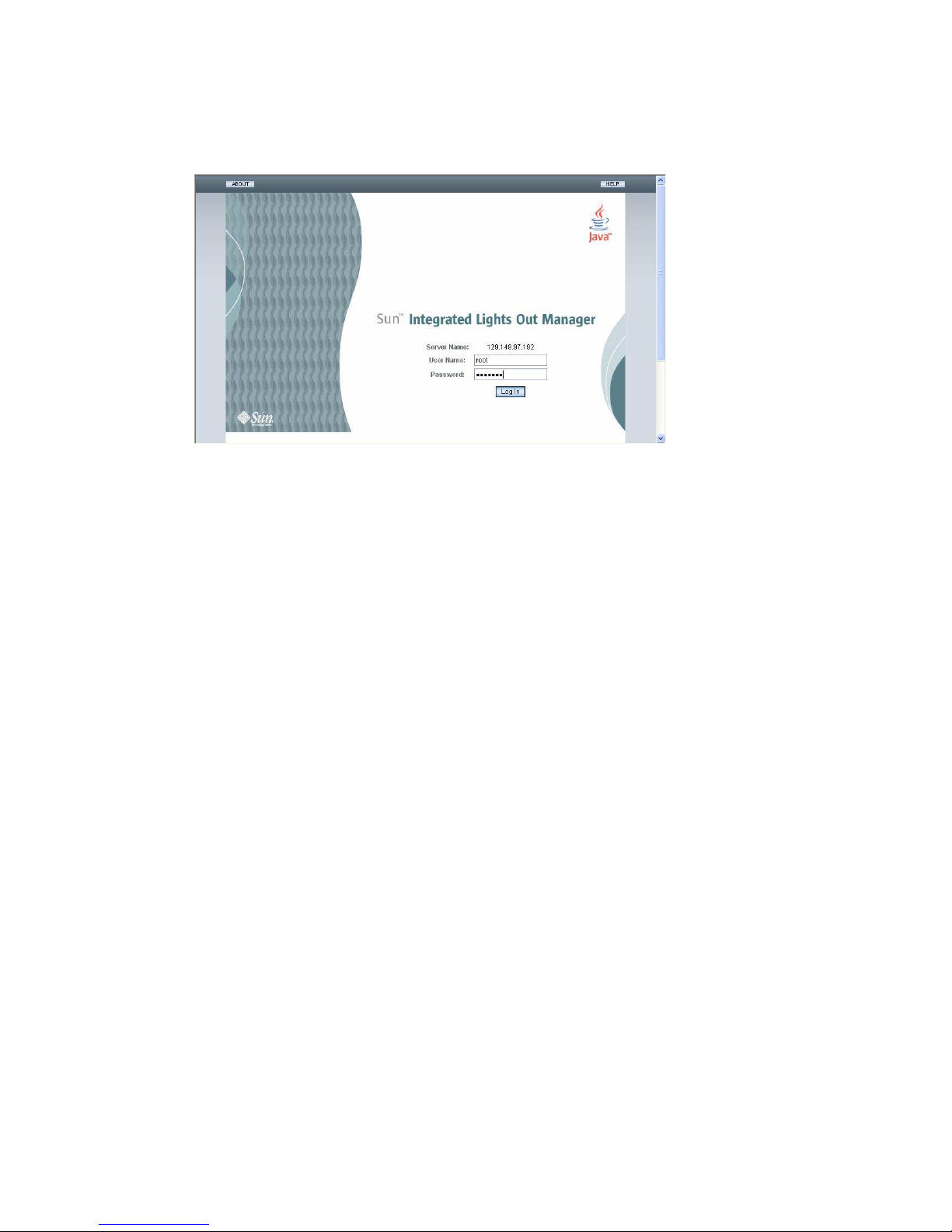
FIGURE 2-1 Integrated Lights Out Manager Login Page
ILOM consists of four components, three of which are on your host server and one
that is on the client system that accesses your host server. The four components are
as follows:
■ ILOM SP hardware. Your server is equipped with a service processor that
performs the following functions:
■ Monitors the status and configuration of field-replaceable components of your
server, such as fans, disk drives, and power supplies.
■ Provides serial and Ethernet connections to external terminals or local area
networks (LANs).
■ ILOM SP firmware. A library of system management firmware applications that
is preinstalled on the SP. This ILOM firmware is operating system independent.
These firmware applications provide the following system management interfaces
into your server:
■ A web-based graphical interface
■ A Secure Shell (SSH) command-line interface
■ An IPMI v2.0 command interface
■ A Simple Network Management Protocol (SNMP) v1, v2c, or v3 interface
These interfaces call the same underlying system management functions on your
service processor, so you can choose to work with one or more of these ILOM
interfaces to integrate with the other management interfaces running in your data
center.
■ Remote Console application. The Remote Console application enables remote
clients to view the graphical console of your host server as though they were
directly attached to its video connector. The Remote Console is a mirror of the
1024x768 output from the server’s VGA video connector. The remote keyboard,
mouse, CD drive, or diskette drive will appear as standard USB devices.
Page 25

Chapter 2 Setting Up the Sun Fire X2250 Server Software 15
Note – The Remote Console application is not required on the client systems, but a
web browser and Sun Java
™
runtime environment version 5.0 or later are required
on the client systems. You can download Java free from http://java.sun.com.
■ Client-side Secure Shell application. To access the ILOM SP through a remote
Secure Shell (SSH), you must install a Secure Shell communications application on
the remote client system (server, workstation, or laptop). Many Secure Shell
communications applications are available from commercial or open-source
distribution. Refer to http://www.openssh.org for information about opensource client-side SSH applications.
Sun Microsystems
™
has configured the ILOM hardware and firmware on your
server to reflect the most common default settings used in the field. It is unlikely
that you will need to change these defaults.
Page 26

16 Sun Fire X2250 Server Installation Guide • May 2008
Connecting to the ILOM Service
Processor
There are two methods for connecting to the ILOM SP to perform initial setup and
configuration. Use the procedure that you prefer:
■ “To Connect to ILOM Using a Serial Connection” on page 16
■ “Connecting to ILOM Using an Ethernet Connection” on page 18
▼ To Connect to ILOM Using a Serial Connection
Use this procedure to establish a serial connection to the ILOM SP so that you can
perform initial configuration of ILOM.
Note – This procedure assumes that you have already completed the hardware
setup and have applied standby power to your server, as described in Chapter 1.
1. Verify that your terminal, laptop, or terminal server is operational.
2. Configure that terminal device or the terminal emulation software running on a
laptop or PC to the following settings:
■ 8N1: eight data bits, no parity, one stop bit
■ 9600 baud
■ Disable hardware flow control (CTS/RTS)
■ Disable software flow control (XON/XOFF)
3. Connect a serial cable from the RJ-45 SER MGT port on the server’s back panel
to a terminal device. See
FIGURE 1-2 for the location of this port.
Page 27

Chapter 2 Setting Up the Sun Fire X2250 Server Software 17
4. Press Enter on the terminal device to establish a connection between that
terminal device and the ILOM SP.
The SP eventually displays a login prompt, such as the following example:
SUNSP0003BA84D777 login:
In this example login prompt:
■ The string SUNSP is the same for all SPs.
■ 0003BA84D777 is the Ethernet MAC address of the particular SP. This will be
different for each server.
5. Log in to ILOM.
a. Type the default user name: root
b. Type the default password: changeme.
Once you have successfully logged in, the SP displays its default command
prompt:
->
You can now run CLI commands to configure ILOM for the server ’s user
accounts, network settings, access lists, alerts, and other parameters. For detailed
instructions on CLI commands, see the Sun Integrated Lights Out Manager 2.0
User’s Guide (820-1188).
For instructions on configuring static network settings using the CLI, see
“Configuring ILOM Using Static Ethernet Settings” on page 21.
6. To start the serial console, type:
cd /SP/console
start
Note – You can switch back to the SP CLI from the serial console by entering the
Esc ( key sequence.
7. After configuring the server, continue with “Setting Up Platform Operating
System and Driver Software” on page 24.
Page 28

18 Sun Fire X2250 Server Installation Guide • May 2008
Connecting to ILOM Using an Ethernet
Connection
To access the full range of ILOM functionality such as the graphical user interface
(GUI), you must connect the server’s Ethernet port to your local area network (LAN)
and configure your Ethernet connection.
ILOM supports Dynamic Host Configuration Protocol (DHCP) and static IP
addressing.
■ To configure the Ethernet connection using DHCP, see “To Configure ILOM
Ethernet Settings Using DHCP” on page 18.
■ To configure the Ethernet connection using a static IP address, see “Configuring
ILOM Using Static Ethernet Settings” on page 21.
Configuring ILOM Using Dynamic Ethernet Settings
You can configure the Ethernet settings using DHCP.
▼ To Configure ILOM Ethernet Settings Using DHCP
Note – This procedure assumes that you have already completed the hardware
setup and have applied standby power for your server, as described in Chapter 1.
1. Verify that your DHCP server is configured to accept new media access control
(MAC) addresses by checking with your system administrator.
2. Connect an Ethernet cable to the server’s RJ-45 NET MGT Ethernet port. See
FIGURE 1-2.
If the ILOM SP is not using static IP addresses, it broadcasts a DHCPDISCOVER
packet with the ID of its MAC address. A DHCP server on your LAN returns a
DHCPOFFER packet containing an IP address and other information. The ILOM
SP then manages its “lease” of the IP address that was assigned to it by the DHCP
server.
3. Obtain the ILOM SP IP address from one of the following locations. Record the
IP address for future reference.
■ CLI commands. The SP has a serial port to which you can attach a terminal
device. If you log in to the SP and enter the CLI command show /SP/network,
the SP displays the current IP address. Continue with Step 4.
Page 29

Chapter 2 Setting Up the Sun Fire X2250 Server Software 19
■ System BIOS Setup screen. Press F2 during during the server power-on, then
choose Advanced
→ IPMI 2.0 Configuration → Set LAN Configuration → IP
address. Continue with Step 4.
■ DHCP server log files. If you use this method, use Step a through Step c below.
Otherwise, skip to Step 4.
a. Identify the MAC address of the ILOM SP from one of the following
locations. Record the MAC address for future reference.
■ CLI commands. The SP has a serial port to which you can attach a terminal
device. If you log in to the SP and type the CLI command
show /SP/network, the SP displays the current MAC address.
■ Customer Information Sheet. This document is shipped with your server.
■ System BIOS Setup screen. Press F2 during power-on, then choose Advanced
→ IPMI 2.0 Configuration → Set LAN Configuration → MAC address.
b. Log in to your DHCP server and view its DHCP log file.
Note – Different DHCP server applications running on different operating systems
store these log files in different locations. Consult your DHCP system administrator
to locate the correct path to the log file.
c. Identify the IP address in the log file that corresponds to the MAC address
of your ILOM SP.
Typically, DHCP log file entries are individual lines with the following commaseparated fields:
ID, Date, Time, Description, IP Address, Host Name, MAC Address
Locate the MAC address of your ILOM SP in the MAC Address (seventh) field
of the correct DHCP file entry and record the corresponding value of the IP
Address (fifth) field. This is the IP address that you must use to access the
system management firmware applications on your ILOM SP.
4. Open a session to the ILOM SP using the IP address that you obtained in
Step 3.
You can use the CLI or the GUI interface.
■ To establish a Secure Shell (SSH) connection to the ILOM SP CLI, type the
appropriate connection command in the SSH application. For example, to connect
to the SP with the DHCP-assigned IP address of 129.144.82.20, type the following
command:
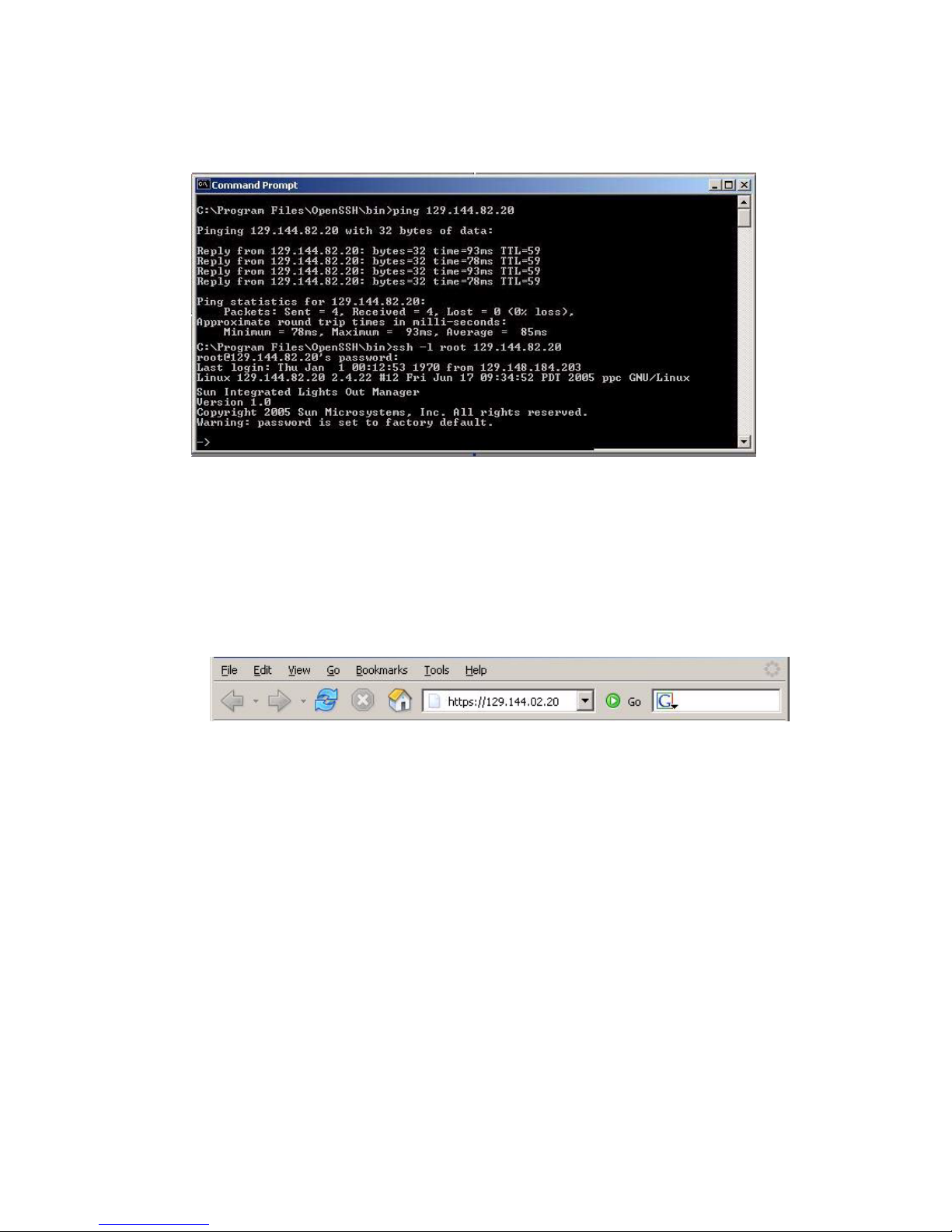
# ssh -l root 129.144.82.20
The default user name is root, which was included in the ssh command.
When you are prompted, enter the default password for the SP, changeme.You
can then enter commands to manage user accounts or to monitor the status of
devices on your server. See the example in
FIGURE 2-2.
Page 30
20 Sun Fire X2250 Server Installation Guide • May 2008
FIGURE 2-2 Opening a Session With an SSH Command-Line Interface
■ To establish a connection to the ILOM SP web interface, type the IP address of the
ILOM SP in the browser locator box and press Enter.
For example, if the IP address for your ILOM SP was 129.144.02.20, you would
enter it as shown in
FIGURE 2-3. The first web page prompts you for the default
username, root, and the default password, changeme.
FIGURE 2-3 Opening a Session With a Web Interface
5. After you have entered the user name and password in either the CLI or web
interface, you can use the interface to configure your ILOM SP.
For detailed instructions on configuring your system, see the Sun Integrated Lights
Out Manager 2.0 User’s Guide (820-1188).
6. Continue with “Setting Up Platform Operating System and Driver Software” on
page 24.
Page 31

Chapter 2 Setting Up the Sun Fire X2250 Server Software 21
Configuring ILOM Using Static Ethernet Settings
As an alternative to having your DHCP server assign an IP address to your ILOM
SP, you can also assign a static IP address to it. You can do this by using the web
interface, by using the CLI over the network or serial port, or by using the server ’s
BIOS Setup utility. Use the procedure you prefer.
■ “To Configure Static IP Addresses Using the Web Interface” on page 21
■ “To Configure Static IP Addresses Using the CLI” on page 22
■ “To Configure Static IP Addresses Using the BIOS Setup Utility” on page 23
▼ To Configure Static IP Addresses Using the Web
Interface
1. Determine the current IP address of the ILOM SP from one of the following
locations:
■ CLI command. The SP has a serial port to which you can attach a terminal device.
If you log in to the SP and enter the CLI command show /SP/network, the SP
displays the current IP address.
■ System BIOS Setup screen. Press F2 during power-on, then choose Advanced →
IPMI 2.0 Configuration → Set LAN Configuration → IP address.
2. Connect to the ILOM SP through a web browser running on a remote system.
To establish a connection to the ILOM SP web interface, type the IP address of the
ILOM SP in the browser locator box and press Enter. See
FIGURE 2-3 for an
example.
The ILOM web interface Login screen appears.
3. Log in to the web interface using the default user name, root, and the default
password, changeme.
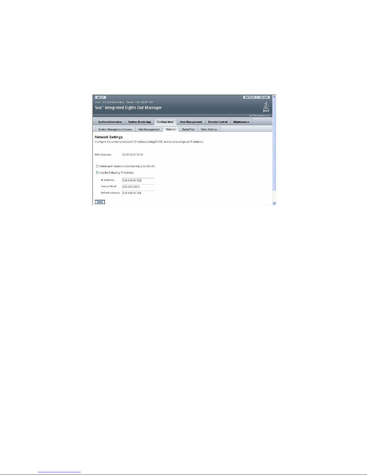
4. Choose the Configuration tab and its Network tab to display information about
the current network configuration of your ILOM SP. See
FIGURE 2-4.
Page 32
22 Sun Fire X2250 Server Installation Guide • May 2008
5. Select the Use the Following IP Address option and type your static IP address
information. See the example in
FIGURE 2-4.
FIGURE 2-4 Integrated Lights Out Manager Network Settings Page
▼ To Configure Static IP Addresses Using the CLI
1. Log into the CLI using SSH or by connecting to the serial port.
To establish a Secure Shell (SSH) connection to the ILOM CLI, type the
appropriate connection command in the SSH application. For example, to connect
to the SP with the DHCP-assigned IP address of 129.144.82.20, you would type
the following command:
# ssh -l root 129.144.82.20
See the example in
FIGURE 2-2.
2. Type the following commands, using your own addresses in place of the
examples below:
The addresses shown in the commands below are examples.
cd /SP/network
set pendingipaddress=129.144.82.26
set pendingipnetmask=255.255.255.0
set pendingipgateway=129.144.82.254
set pendingipdiscovery=static
set commitpending=true
Page 33

Chapter 2 Setting Up the Sun Fire X2250 Server Software 23
▼ To Configure Static IP Addresses Using the BIOS Setup
Utility
1. Enter the BIOS Setup utility by pressing the F2 key while the system is
powering on and performing the power-on self-test (POST).
2. When the BIOS Main menu screen is displayed, select Advanced.
3. From the Advanced menu screen, select IPMI 2.0 Configuration.
4. From the IPMI 2.0 Configuration screen, select LAN Configuration.
5. From the LAN Configuration screen, select IP Address.
6. From the IP Address screen, select IP Address Mode.
7. On the IP Address Mode screen, select Static.
8. Type the static IP address in the IP Address field.
Click ESC to go back and enter the subnet mask and default gateway settings in
their respective fields.
9. Select Commit and press Enter to commit the changes.
10. Select Refresh and press Enter to see your new static IP settings displayed in
the Current IP address in BMC field.
11. Press and release the right arrow key until the Exit menu screen is displayed.
12. Follow the instructions on the Exit menu screen to save your changes and exit
the BIOS Setup utility.
Page 34

24 Sun Fire X2250 Server Installation Guide • May 2008
Setting Up Platform Operating System
and Driver Software
After configuring the ILOM SP with network settings, you can configure a
preinstalled operating system or install a supported Solaris, Linux or Windows
platform operating system and drivers.
■ If your server contains the preinstalled Solaris 10 Operating System, refer to
“Configuring the Preinstalled Solaris 10 Operating System” on page 25 for
instructions on configuring the Solaris OS on your server.
■ For details about installing a supported Solaris, Windows or Linux OS and the
required drivers, refer to Sun Fire X2250 Server Operating System Installation Guide
(820-4592), or the Sun Installation Assistant for Windows and Linux User’s Guide
(820-3357).
■ Refer to the Sun Fire X2250 Server Operating System Installation Guide for
information to manually install and configure a supported Solaris, Windows,
or Linux OS on your server.
■ Refer to the Sun Installation Assistant for Windows and Linux User’s Guide for
information on using the Sun Installation Assistant (SIA) to install and
configure a supported Windows or Linux OS on your server. With SIA, you can
install the OS, the appropriate drviers, and if necessary, additional system
software by simply booting the SIA media and following the prompts.
■ For additional OS considerations specific to this server, refer to the Sun Fire X2250
Server Product Notes (820-4594).
If you do not plan to use an operating system (OS) that is preinstalled on your Sun
Fire X2250 server, install your preferred OS at this time. If the Solaris 10 OS is
preinstalled on the primary boot drive, you will need to remove the OS using the
Erase Primary Boot Disk utility on the Tools & Drivers CD.
See the Sun Fire X2250 Server Operating System Installation Guide (820-4592) for more
information on erasing the primary boot disk and installing an operating system
onto the server.
Page 35

25
CHAPTER
3
Configuring the Preinstalled
Solaris 10 Operating System
This chapter explains the steps for configuring the Solaris™10 Operating System
(OS) that has been preinstalled on your server. The preinstalled version is Solaris 10
8/07 or later.
Before You Begin
Before you begin configuring the preinstalled OS, you need to do the following:
1. Perform initial configuration of the server’s Integrated Lights Out Manager
(ILOM) service processor (SP) and determine the server ’s network settings, as
described in “Connecting to the ILOM Service Processor” on page 16.
2. Gather the information that you will need for the configuration, as listed in
“Installation Worksheet” on page 26.
3. Select your console output. For details, see “Selecting Your Console Output” on
page 29.
Page 36

26 Sun Fire X2250 Server Installation Guide • May 2008
Installation Worksheet
Use the worksheet in TABLE 3-1 to gather the information you need to configure the
preinstalled Solaris 10 OS. You need to collect only the information that applies to
your application.
TABLE 3-1 Worksheet for Installation
Information for Installation Description or Example
Your Answers:
Defaults are noted
with an asterisk. (*)
Language Choose from the list of available languages for the
Solaris 10 software.
English*
Locale Choose your geographic region from the list of available
locales.
English (C - 7-bit
ASCII)*
Terminal Choose the type of terminal that you are using from the
list of available terminal types.
Network connection Is the system connected to a network? • Networked
• Nonnetworked*
DHCP Can the system use Dynamic Host Configuration
Protocol (DHCP) to configure its network interfaces?
•Yes
• No*
If you are not
using DHCP,
note the
network
address:
IP address If you are not using DHCP, supply the IP address for the
system.
Example: 129.200.9.1
Subnet If you are not using DHCP, is the system part of a
subnet?
If yes, what is the netmask of the subnet?
Example: 255.255.0.0
255.255.0.0*
IPv6 Do you want to enable IPv6 on this machine? • Yes
• No*
Host name A host name that you choose for the system.
Kerberos Do you want to configure Kerberos security on this
machine? If yes, gather the following information:
Default Realm:
Administration Server:
First KDC:
(Optional) Additional KDCs:
•Yes
• No*
Page 37

Chapter 3 Configuring the Preinstalled Solaris 10 Operating System 27
Name service: if
the system uses
a name service,
provide the
following
information.
Name service Which name service should this system use? • NIS+
• NIS
• DNS
• LDAP
• None*
Domain
name
Provide the name of the domain in which the system
resides.
NIS+ and
NIS
Do you want to specify a name server or let the
installation program find one?
• Specify One
• Find One*
DNS Provide IP addresses for the DNS server. You must enter
at least one IP address, but you can enter up to three
addresses.
You can also enter a list of domains to search when a
DNS query is made.
Search Domain:
Search Domain:
Search Domain:
LDAP Provide the following information about your LDAP
profile:
Profile name:
Profile server:
If you specify a proxy credential level in your LDAP
profile, gather this information:
Proxy-Bind Distinguished Name:
Proxy-Bind Password:
TABLE 3-1 Worksheet for Installation (Continued)
Information for Installation Description or Example
Your Answers:
Defaults are noted
with an asterisk. (*)
Page 38

28 Sun Fire X2250 Server Installation Guide • May 2008
Default route Do you want to specify a default route IP address or let
the Solaris installation program find one?
The default route provides a bridge that forwards traffic
between two physical networks. An IP address is a
unique number that identifies each host on a network.
You have the following choices:
• You can specify the IP address. An
/etc/defaultrouter file is created with the
specified IP address. When the system is rebooted, the
specified IP address becomes the default route.
• You can let the Solaris installation program detect an
IP address. However, the system must be on a subnet
that has a router that advertises itself by using the
ICMP router discovery protocol. If you are using the
command-line interface, the software detects an IP
address when the system is booted.
• You can choose None if you do not have a router or
do not want the software to detect an IP address at
this time. The software automatically tries to detect an
IP address on reboot.
• Specify One
• Detect One
• None*
Time zone How do you want to specify your default time zone? • Geographic
region*
• Offset from GM
• Time zone file
Root password Choose a root password for the system.
TABLE 3-1 Worksheet for Installation (Continued)
Information for Installation Description or Example
Your Answers:
Defaults are noted
with an asterisk. (*)
Page 39

Chapter 3 Configuring the Preinstalled Solaris 10 Operating System 29
Selecting Your Console Output
Unlike with SPARC®systems, you will not see the output of the preinstalled
Solaris 10 image through a monitor when you power on the server. Instead, the
output of the preinstalled image is directed to a serial console.
GRUB, the open source boot loader, is the default boot loader. The boot loader is the
first software program that runs after you power on a system.
From the GRUB menu, you have the option of displaying the installation process to
a VGA connection (video port), as shown below.
*******************************************************************
* Solaris 10 5/08 s10x_u5wos_10 X86 - Serial Port (ttya) *
* Solaris 10 5/08 s10x_u5wos_10 X86 - Graphics Adapter *
* Solaris failsafe *
* *
* *
* *
* *
* *
*******************************************************************
Note – The first line of the above figure shows the default startup mode.
Example
To display output to the video port, choose the following option:
Solaris 10 5/08 s10x_u5wos_10 X86 - Graphics Adapter
Page 40

30 Sun Fire X2250 Server Installation Guide • May 2008
Configuring the Preinstalled Solaris 10
Operating System
Note – Before you perform this procedure, you need to set up the service processor.
If you have not done so, see “Before You Begin” on page 25.
Use the information that you gathered in “Installation Worksheet” on page 26 as you
perform the configuration.
After configuring the ILOM SP, you can configure the preinstalled Solaris 10
Operating System (OS) by using another system to connect to the server, or install a
Linux or Windows platform operating system. The possible ways to do this are
described here:
■ “To Connect to the Server Using the Service Processor’s IP Address” on page 31
If you use this method, you first need to determine the service processor’s IP
address and the server must be connected to the network.
■ “To Connect to the Server Using a Terminal Program” on page 32
If you use this method, you do not need to determine the service processor’s IP
address, but you will need to have a cable connection from the server to the serial
port of a host system.
■ If you want to install a supported Windows or Linux (and Solaris) OS and the
required drivers, refer to the Sun Fire X2250 Server Operating System Installation
Guide (820-4592).
■ For additional OS considerations specific to this server, refer to the Sun Fire X2250
Server Product Notes (820-4594)
Page 41

Chapter 3 Configuring the Preinstalled Solaris 10 Operating System 31
▼ To Connect to the Server Using the Service
Processor’s IP Address
Note – This procedure assumes that you have connected the server to your network
through an Ethernet cable.
1. Verify that the communication properties of the serial port of the system are set
to the defaults.
The default settings are 9600 baud, 8N1 (eight data bits, no parity, one stop bit),
disable flow control.
2. If you have not already done so, determine the service processor’s IP address:
a. Power on main power to the server by using a non-metallic stylus to press
the recessed Power button on the front panel.
Power-on self-test (POST) messages appear on your screen as the OS boots.
b. Initialize the BIOS Setup utility by pressing the F2 key while the system is
performing the power-on self-test (POST).
c. When the main BIOS screen is displayed, select Advanced.
d. When the Advanced screen is displayed, select IPMI 2.0 Configuration.
e. When the IPMI 2.0 Configuration screen is displayed, select the LAN
Configuration menu item.
f. Select the IP Address menu item.
The service processor’s IP address is displayed using the following format:
Current IP address in BMC: xxx.xxx.xxx.xxx
3. Using a client system, establish a Secure Shell (SSH) connection to the service
processor’s IP address and log in as an Administrator.
ssh -l root sp_ip_address
password: changeme
You may connect to the ILOM service processor CLI, using the serial management
port on the rear of the server, or by using SSH over the network.
4. To access the server serial port, you must connect to the ILOM service processor
CLI. Type:
start /SP/console
A message appears prompting you to confirm that you want to start the SP
console.
Page 42

32 Sun Fire X2250 Server Installation Guide • May 2008
5. Continue the operation for starting the SP console by typing y (yes) and
pressing Enter.
The GRUB boot loader menu appears.
6. Power on main power to the server by using a non-metallic stylus to press the
recessed Power button on the front panel.
POST messages appear on your screen as the OS boots.
7. To make Solaris output appear on the server VGA (video port), you must select
the video port from the GRUB boot loader menu, as shown on “Selecting Your
Console Output” on page 29.
8. If you have changed the SP serial port default settings, make sure you reset
them to the default settings.
9. Follow the Solaris 10 on-screen prompts.
Use the information gathered in “Installation Worksheet” on page 26 to help you
enter the system and network information as you are prompted.
The screens that are displayed will vary, depending on the method that you chose
for assigning network information to the server (DHCP or static IP address).
After you have entered the system-configuration information, the server completes
the boot process and displays the Solaris login prompt. Refer to the Sun Fire X2250
Operating Systems Installation Guide (820-4592) for information about configuring the
Solaris OS.
▼ To Connect to the Server Using a Terminal
Program
1. Use a cable to connect the serial port of the server to the serial port of the host
system.
2. Verify that the communication properties of the serial port of the system are set
to the defaults.
The default settings are 9600 baud, 8N1 (eight data bits, no parity, one stop bit),
disable flow control.
3. Start a terminal session to capture the serial port output by doing one of the
following:
■ On a client running Solaris OS, type:
$tip -9600 /dev/ttya
■ On a client running Windows, start a program such as Hyperterminal.
Page 43

Chapter 3 Configuring the Preinstalled Solaris 10 Operating System 33
■ On a client running Linux, start a program such as Minicom, a text-based serial
communication program that is included in the Linux distributions. For more
information, see the man pages included in the Linux distribution.
4. Log in to the service processor as an Administrator, for example:
login: root
password: changeme
5. Start the ILOM SP CLI by entering the following:
start /SP/console
6. Power on main power to the server by using a non-metallic stylus to press the
recessed Power button on the front panel.
POST messages appear on your screen as the OS boots.
7. Follow the Solaris 10 preinstallation on-screen prompts.
Use the information gathered in “Installation Worksheet” on page 26 to help you
enter the system and network information as you are prompted.
The screens that are displayed will vary, depending on the method that you chose
for assigning network information to the server (DHCP or static IP address).
After you have entered the system-configuration information, the server completes
the boot process and displays the Solaris login prompt. Refer to the Sun Fire X2250
Operating Systems Installation Guide (820-4592) for information about configuring the
Solaris OS.
Solaris 10 Operating System User
Information
This section provides pointers to information about the Solaris 10 operating system.
Accessing Solaris 10 OS User Documentation
You can access the various collections of the Solaris 10 OS user documentation at:
http://docs.sun.com/app/docs/prod/solaris.10
Specifically, you can access the Solaris 10 OS Release and Installation collection at:
http://docs.sun.com/app/docs/coll/1236.1
Page 44

34 Sun Fire X2250 Server Installation Guide • May 2008
Downloading Solaris 10 OS Software
If you need to install the Solaris 10 OS or reinstall the OS after removing it, you can
download the CD or DVD image from the following URL:
http://www.sun.com/software/solaris/get.jsp
See the Sun Fire X2250 Server Operating System Installation Guide (820-4592) for
specific instructions on Solaris 10 OS installation.
Solaris 10 OS Training
Sun provides flexible training options that accommodate your personal schedule
and learning style. The training options include instructor-led, web-based online,
CD-ROM, and Live Virtual Class. For Solaris 10 Training and Certification options at
a glance, please visit:
http://www.sun.com/training/catalog/solaris10.html
 Loading...