

Page 1

Sun Fire V60x and Sun Fire V65x
Servers—Troubleshooting Guide
Troubleshooting Guide
Sun Microsystems, Inc.
4150 Network Circle
Santa Clara, CA 95054 U.S.A.
650-960-1300
Part No. 817-2024-12
November 2003, Revision A
Submit comments about this document at:
http://www.sun.com/hwdocs/feedback
Page 2

Copyright 2003 Sun Microsystems, Inc., 4150 Network Circle, Santa Clara, California 95054, U.S.A. All rights reserved.
Sun Microsystems, Inc. has intellectual property rights relating to technology that is described in this document. In particular, and without
limitation, these intellectual property rights may include one or more of the U.S. patents listed at
more additional patents or pending patent applications in the U.S. and in other countries.
This document and the product to which it pertains are distributed under licenses restricting their use, copying, distribution and
decompilation. No part of the product or of this document may be reproduced in any form by any means without prior written authorization of
Sun and its licensors, if any.
Third-party software, including font technology, is copyrighted and licensed from Sun suppliers.
Parts of the product may be derived from Berkeley BSD systems, licensed from the University of California. UNIX is a registered trademark in
the U.S. and in other countries, exclusively licensed through X/Open Company, Ltd.
Sun, Sun Microsystems, the Sun logo, AnswerBook2, docs.sun.com, Solaris and Sun Fire are trademarks or registered trademarks of Sun
Microsystems, Inc. in the U.S. and in other countries.
All SPARC trademarks are used under license and are trademarks or registered trademarks of SPARC International, Inc. in the U.S. and in other
countries. Products bearing SPARC trademarks are based upon an architecture developed by Sun Microsystems, Inc.
The OPEN LOOK and Sun™ Graphical User Interface was developed by Sun Microsystems, Inc. for its users and licensees. Sun acknowledges
the pioneering efforts of Xerox in researching and developing the concept of visual or graphical user interfaces for the computer industry. Sun
holds a non-exclusive license from Xerox to the Xerox Graphical User Interface, which license also covers Sun’s licensees who implement OPEN
LOOK GUIs and otherwise comply with Sun’s written license agreements.
U.S. Government Rights—Commercial use. Government users are subject to the Sun Microsystems, Inc. standard license agreement and
applicable provisions of the FAR and its supplements.
DOCUMENTATION IS PROVIDED “AS IS” AND ALL EXPRESS OR IMPLIED CONDITIONS, REPRESENTATIONS AND WARRANTIES,
INCLUDING ANY IMPLIED WARRANTY OF MERCHANTABILITY, FITNESS FOR A PARTICULAR PURPOSE OR NON-INFRINGEMENT,
ARE DISCLAIMED, EXCEPT TO THE EXTENT THAT SUCH DISCLAIMERS ARE HELD TO BE LEGALLY INVALID.
Copyright 2003 Sun Microsystems, Inc., 4150 Network Circle, Santa Clara, California 95054, États-Unis. Tous droits réservés.
Sun Microsystems, Inc. a les droits de propriété intellectuelle relatants à la technologie qui est décrite dans ce document. En particulier, et sans la
limitation, ces droits de propriété intellectuelle peuvent inclure un ou plus des brevets américains énumérés à
http://www.sun.com/patents
dans les autres pays.
Ce produit ou document est protégé par un copyright et distribué avec des licences qui en restreignent l’utilisation, la copie, la distribution et la
décompilation. Aucune partie de ce produit ou document ne peut être reproduite sous aucune forme, par quelque moyen que ce soit, sans
l’autorisation préalable et écrite de Sun et de ses bailleurs de licence, s’il y en a.
Le logiciel détenu par des tiers, et qui comprend la technologie relative aux polices de caractères, est protégé par un copyright et licencié par des
fournisseurs de Sun.
Des parties de ce produit pourront être dérivées des systèmes Berkeley BSD licenciés par l’Université de Californie. UNIX est une marque
déposée aux États-Unis et dans d’autres pays et licenciée exclusivement par X/Open Company, Ltd.
Sun, Sun Microsystems, le logo Sun, Java, JumpStart, Solaris et Sun Fire sont des marques de fabrique ou des marques déposées de Sun
Microsystems, Inc. aux États-Unis et dans d’autres pays.
Toutes les marques SPARC sont utilisées sous licence et sont des marques de fabrique ou des marques déposées de SPARC International, Inc.
aux États-Unis et dans d’autres pays. Les produits portant les marques SPARC sont basés sur une architecture développée par Sun
Microsystems, Inc.
L’interface d’utilisation graphique OPEN LOOK et Sun a été développée par Sun Microsystems, Inc. pour ses utilisateurs et licenciés. Sun
reconnaît les efforts de pionniers de Xerox pour la recherche et le développement du concept des interfaces d’utilisation visuelle ou graphique
pour l’industrie de l’informatique. Sun détient une license non exclusive de Xerox sur l’interface d’utilisation graphique Xerox, cette licence
couvrant également les licenciées de Sun qui mettent en place l’interface d’utilisation graphique OPEN LOOK et qui en outre se conforment aux
licences écrites de Sun.
LA DOCUMENTATION EST FOURNIE «EN L’ÉTAT» ET TOUTES AUTRES CONDITIONS, DÉCLARATIONS ET GARANTIES EXPRESSES
OU TACITES SONT FORMELLEMENT EXCLUES, DANS LA MESURE AUTORISÉE PAR LA LOI APPLICABLE, Y COMPRIS NOTAMMENT
TOUTE GARANTIE IMPLICITE RELATIVE À LA QUALITÉ MARCHANDE, À L’APTITUDE À UNE UTILISATION PARTICULIÈRE OU À
L’ABSENCE DE CONTREFAÇON.
et un ou les brevets plus supplémentaires ou les applications de brevet en attente dans les États-Unis et
http://www.sun.com/patents
and one or
Please
Recycle
Page 3

Contents
Safety and Compliance Information xvii
Who Should Use This Book xviii
How This Manual is Organized xviii
Typographic Conventions xviii
Related Documentation xix
Ordering Sun Documents xix
Shell Prompts in Command Examples xix
Notice xx
Support xx
Sun Welcomes Your Comments xxi
1. Troubleshooting Guidelines 1–1
1.1 Startup-related Issues 1–1
1.1.1 Ethernet Port Delay 1–1
1.1.2 USB-Connected External CD-ROM Drive Will Not Function 1–2
1.1.3 Inability to Boot Server When an External SCSI Hard Drive is
1.1.4 PS/2 Mouse Misidentification 1–2
Connected 1–2
iii
Page 4

1.2 Resetting the Server 1–3
1.2.1 Software Mechanisms 1–3
1.2.1.1 Software Shutdown Commands for Linux 1–3
1.2.1.2 Software Shutdown Commands for Solaris 1–3
1.2.2 Hardware Mechanisms 1–4
1.3 Disabling Integrated Components 1–4
1.4 Setting Main Board Jumpers 1–5
1.5 Processor and Heatsink Configurations 1–6
1.5.1 Single or Dual Processor Main Boards 1–6
1.5.2 Supported Processors 1–7
1.5.3 Heatsinks and Air Ducts 1–7
1.5.4 Processor Population Order 1–7
1.5.5 Hyper-threading
TM
CPU Feature 1–8
1.6 Memory Configurations 1–8
1.7 Problems With SNMP 1–9
1.8 Problems With Initial System Startup 1–10
1.8.1 Checklist 1–10
1.9 Problems With New Application Software 1–11
1.10 Problems After the System Has Been Running Correctly 1–12
2. Troubleshooting Specific Problems 2–1
2.1 Preparing the System for Diagnostic Testing 2–1
2.2 Specific Problems and Corrective Actions 2–2
2.2.1 Problems Starting Up 2–3
2.2.1.1 Server Does Not Power On 2–3
2.2.1.2 Front Panel is Unresponsive and Video is Disabled 2–4
2.2.1.3 Server Beeps at Power On or When Booting 2–5
2.2.1.4 Some Hard Drives Do Not Show Up During POST 2–5
2.2.1.5 Server Starts Booting Automatically at Power On 2–7
iv
Sun Fire V60x and Sun Fire V65x Servers—Troubleshooting Guide • November 2003
Page 5

2.2.1.6 Power-On Self-Test (POST) 2–7
2.2.1.7 Verifying Proper Operation of Key System LEDs 2–8
2.2.1.8 Confirming Loading of the Operating System 2–8
2.2.1.9 KVM (PS/2 Keyboard-Video-Mouse) Unit Causes
System To Hang During POST 2–8
2.2.2 Power LED Does Not Light 2–9
2.2.3 Video Problems 2–10
2.2.3.1 No Video Appears on the Screen 2–10
2.2.3.2 Xserver Has Not Started 2–11
2.2.3.3 Characters Are Distorted or Incorrect 2–11
2.2.4 System Cooling Fans Do Not Rotate Properly 2–12
2.2.5 Disk Drive Activity Light Does Not Light 2–12
2.2.6 CD-ROM Drive Activity Light Does Not Light 2–12
2.2.7 Cannot Connect to a Server 2–13
2.2.8 Problems with Network 2–13
2.2.9 Problems with Application Software 2–14
2.2.10 Bootable CD-ROM Is Not Detected 2–14
2.2.11 Memory Configuration Errors 2–15
2.2.11.1 Memory DIMM Population Order 2–15
2.2.11.2 Soft Reboot Errors 2–16
2.2.11.3 Faulty Memory DIMMs 2–18
2.3 Other Problems 2–20
2.4 General Board and Feature Issues 2–21
3. Troubleshooting the Server Using Built-In Tools 3–1
3.1 Diagnosing System Errors 3–1
3.1.1 LEDs 3–1
3.1.2 Beep Codes 3–2
3.1.3 POST Screen Messages 3–2
v
Page 6

3.1.4 System Utilities 3–2
3.1.4.1 Platform Confidence Test (PCT) 3–2
3.1.4.2 System Setup Utility (SSU) 3–2
3.2 LEDs and Pushbuttons 3–3
3.2.1 Front Panel LEDs and Pushbuttons 3–4
3.2.1.1 Front Panel LEDs 3–5
3.2.1.2 Front Panel Pushbuttons 3–6
3.2.2 Rear Panel LEDs 3–7
3.2.3 Front-Panel System Status LED 3–9
3.2.4 Rear Panel Power Supply Status LED 3–11
3.2.5 Server Main Board Fault LEDs 3–13
3.2.6 System ID LEDs 3–15
3.3 Power-On Self Test (POST) 3–15
3.3.1 POST Screen Messages 3–16
3.3.2 POST Error Beep Codes 3–19
3.3.2.1 BIOS Recovery Beep Codes 3–21
3.3.3 POST Progress Code LED Indicators 3–22
3.4 Contacting Technical Support 3–29
4. Powering On and Configuring the Server 4–1
4.1 Jumper Locations 4–2
4.2 Setting the Serial COM2 Port Jumper 4–4
4.3 Powering On 4–5
4.4 Clearing CMOS 4–6
4.4.1 Using the Front Panel 4–6
4.4.2 Using the Clear CMOS Jumper 4–7
vi
Sun Fire V60x and Sun Fire V65x Servers—Troubleshooting Guide • November 2003
Page 7

4.5 Booting Up 4–8
4.5.1 Boot Options 4–9
4.5.1.1 BIOS Setup Utility <F2> 4–9
4.5.1.2 Service Partition <F4> 4–12
4.5.1.3 Network Boot <F12> 4–13
4.5.1.4 Choose Boot Device <ESC> 4–13
4.5.2 Other Bootup Items 4–14
4.5.2.1 Ethernet Port Delay 4–14
4.5.2.2 USB-Connected External CD-ROM Drives 4–14
4.5.2.3 Booting the Server When an External SCSI Hard Drive is
Connected 4–15
4.5.2.4 PS/2 Mouse Misidentification 4–15
4.6 Loading the Operating System 4–16
4.7 Hyper-threading
TM
CPU Feature 4–16
4.8 Configuring an External Serial Console 4–17
4.9 Fault Resilient Booting (FRB) 4–19
4.9.1 FRB3 4–20
4.9.2 FRB2 4–20
4.10 Enabling USB Keyboard and Mouse Operation 4–23
4.11 Using the Service Partition Menu 4–24
4.11.1 Create Diskettes 4–25
4.11.2 System Utilities 4–26
4.11.2.1 Run System Setup Utility 4–27
4.11.2.2 Using the SSU to Manage Logs, Records, Hardware, and
Events 4–30
4.11.2.3 Run Platform Confidence Test (PCT) 4–31
4.11.2.4 Run Baseboard Management Controller (BMC)
Firmware Update 4–43
4.11.2.5 Run HSC Firmware Update 4–43
vii
Page 8

4.11.2.6 Run Field Replaceable Unit/Sensor Data Record
(FRU/SDR) Update3 4–44
4.11.2.7 Run BIOS Update (reboot required) 4–44
4.11.2.8 Reboot to Service Partition 4–44
4.11.2.9 Reboot System 4–44
4.12 Using the Sun Diagnostics CD 4–45
4.12.1 Create Diskettes 4–46
4.12.2 Run System Utilities 4–46
4.12.3 Service Partition 4–47
4.12.4 Restoring the Service Partition 4–48
4.13 Updating the Server Configuration 4–50
4.13.1 Using the Diskette to Update the Server BIOS 4–50
4.13.2 Recovering the BIOS 4–53
4.14 Restarting and Shutting Down 4–55
4.14.1 Software Mechanisms 4–55
4.14.1.1 Software Shutdown Commands for Linux 4–55
4.14.1.2 Software Shutdown Commands for Solaris 4–55
4.14.2 Hardware Mechanisms 4–56
5. Maintaining the Server 5–1
5.1 Tools and Supplies Needed 5–2
5.2 Determining a Faulty Component 5–2
5.3 Safety: Before You Remove the Cover 5–2
5.4 Removing and Replacing the Cover 5–3
5.5 Customer Replaceable Unit (CRU) Procedures 5–4
5.5.1 Front Bezel 5–5
5.5.2 Floppy/DVD/CD-ROM Combo Module 5–7
viii
Sun Fire V60x and Sun Fire V65x Servers—Troubleshooting Guide • November 2003
Page 9

5.5.3 Memory 5–9
5.5.3.1 Sun Fire V60x Server DIMM Replacement 5–10
5.5.3.2 Sun Fire V65x Server DIMM Replacement 5–13
5.5.3.3 Installing the DIMM Fan (Sun Fire V65x Server Only)
5–14
5.5.4 Replacing a Server CPU and Heatsink 5–16
5.5.4.1 Safety Precautions 5–16
5.5.4.2 Sun Fire V60x Server Heatsink and Processor Removal
5–17
5.5.4.3 Sun Fire V60x Server Heatsink and Processor
Replacement 5–19
5.5.4.4 Sun Fire V65x Server Heatsink and Processor Removal
5–22
5.5.4.5 Sun Fire V65x Server Heatsink and Processor
Replacement 5–24
5.5.5 Sun Fire V60x and Sun Fire V65x Servers New CPU and Heatsink
Installation 5–27
5.5.5.1 Safety Precautions 5–27
5.5.6 Power Supply Unit 5–32
5.5.6.1 Sun Fire V60x Server Power Supply 5–32
5.5.6.2 Sun Fire V65x Server Power Supply 5–34
5.5.7 Hard Disk Drives 5–36
5.5.8 Air Baffle 5–38
5.5.8.1 Sun Fire V60x Server Air Baffle Removal 5–38
5.5.8.2 Sun Fire V60x Server Air Baffle Installation 5–39
5.5.8.3 Sun Fire V65x Server Air Baffle Removal 5–40
5.5.8.4 Sun Fire V65x Server Air Baffle Installation 5–40
ix
Page 10

5.5.9 Fan Module 5–41
5.5.9.1 Sun Fire V60x Server Fan Module Removal 5–41
5.5.9.2 Sun Fire V60x Server Fan Module Replacement 5–43
5.5.9.3 Sun Fire V65x Server Fan Module Removal 5–44
5.5.9.4 Sun Fire V65x Server Fan Module Replacement 5–46
5.5.10 PCI Cards 5–47
5.5.11 Battery 5–49
5.5.12 Keyboard/Mouse “Y” Adapter 5–51
5.5.13 Emergency Management Port Cable 5–52
5.5.13.1 Installing the DSR Peripherals Cable 5–52
5.5.13.2 Installing the DCD Modem Cable 5–52
5.6 Field Replaceable Unit (FRU) Procedures 5–54
5.6.1 Server Main Board 5–54
5.6.1.1 Sun Fire V60x Server Main Board Replacement 5–54
5.6.1.2 Sun Fire V65x Server Main Board Replacement 5–58
5.6.2 Cable Kit 5–61
5.6.2.1 Sun Fire V60x Server Cable Kit Removal 5–61
5.6.2.2 Sun Fire V60x Server Cable Kit Installation 5–64
5.6.2.3 Sun Fire V65x Server Cable Kit Removal 5–66
5.6.2.4 Sun Fire V65x Server Cable Kit Installation 5–69
5.6.3 System FRU 5–71
5.6.3.1 Sun Fire V60x and Sun Fire V65x Servers System FRU
Installation 5–71
x
Sun Fire V60x and Sun Fire V65x Servers—Troubleshooting Guide • November 2003
Page 11

Figures
FIGURE 1-1
FIGURE 3-1
FIGURE 3-2
FIGURE 3-3
FIGURE 3-4
FIGURE 3-5
FIGURE 3-6
FIGURE 3-7
FIGURE 4-1
FIGURE 4-2
FIGURE 4-3
FIGURE 4-4
FIGURE 4-5
FIGURE 4-6
Main Board Jumper Locations
Front Panel Pushbuttons and LEDs
Rear Panel LEDs
3–7
Location of Front-Panel System Status LED
1–5
3–4
3–9
Location of Sun Fire V60x and Sun Fire V65x Servers Rear-Panel Power Supply Status
LEDs
Fault and Status LEDs on the Server Board
Location of Front-Panel ID Pushbutton and LED
Examples of POST LED Coding
Main Board Jumper Locations
J5A2 Jumper Block Configured for DSR Signal (pin 7 connected to DSR)
J5A2 Jumper Block Configured for DCD Signal (pin 7 connected to DCD)
Power and Reset Switches on the Front Panel
Location of Clear CMOS Jumper
First BIOS Bootup Screen
3–11
3–13
3–15
3–23
4–2
4–4
4–4
4–5
4–8
4–9
FIGURE 4-7
FIGURE 4-8
FIGURE 4-9
FIGURE 4-10
FIGURE 4-11
FIGURE 4-12
BIOS Setup Utility Main Screen
Default Boot Sequence
BIOS Setup Utility Exit Screen
Network Boot Failed Screen
Boot Device Selection Menu
Rear-Panel Serial COM2 Port
4–10
4–11
4–11
4–13
4–14
4–17
xi
Page 12

FIGURE 4-13
Console Redirection BIOS Setup
4–18
FIGURE 4-14
FIGURE 4-15
FIGURE 4-16
FIGURE 4-17
FIGURE 4-18
FIGURE 4-19
FIGURE 4-20
FIGURE 4-21
FIGURE 4-22
FIGURE 4-23
FIGURE 4-24
FIGURE 4-25
FIGURE 4-26
FIGURE 4-27
FIGURE 4-28
Service Partition Menu
Create Diskettes Submenu
System Utilities Submenu
SSU Main Window
Multiboot Add-in Window
Security Main Window
Reboot Prompt
4–32
Warning Prompt
Platform Confidence Test Menu
Platform Confidence Quick Test (first screen)
4–24
4–25
4–26
4–27
4–28
4–29
4–33
4–33
4–34
Platform Confidence Quick Test Hardware Test Configuration (last screen)
Platform Confidence Quick Test Progress
Platform Confidence Quick Test Results Summary
Platform Confidence Quick Test Sensor Readings (first screen)
Platform Confidence Quick Test Sensor Readings (second screen)
4–36
4–36
4–37
4–37
4–35
FIGURE 4-29
FIGURE 4-30
FIGURE 4-31
FIGURE 4-32
FIGURE 4-33
FIGURE 4-34
FIGURE 4-35
FIGURE 4-36
FIGURE 4-37
FIGURE 4-38
FIGURE 4-39
FIGURE 4-40
FIGURE 5-1
FIGURE 5-2
Sample RESULT.LOG
4–39
Platform Confidence Comprehensive Test Progress
Platform Confidence Comprehensive Test Results
Boot Complete from the Diagnostics CD
Boot Complete from the Diagnostics CD
Service Partition Administration Menu
Prompt to Begin BIOS Update
BIOS Update in Progress Prompt
First BIOS Update Finished
Second BIOS Update Pass
Verifying the BIOS Version
4–50
4–50
4–51
4–52
4–52
Location of Recovery Boot Jumper
Removing the Cover
5–3
Sun Fire V60x Server Bezel Replacement
4–46
4–48
4–49
4–53
5–5
4–41
4–42
xii
Sun Fire V60x and Sun Fire V65x servers • November 2003
Page 13

FIGURE 5-3
Sun Fire V65x Server Bezel Replacement
5–6
FIGURE 5-4
FIGURE 5-5
FIGURE 5-6
FIGURE 5-7
FIGURE 5-8
FIGURE 5-9
FIGURE 5-10
FIGURE 5-11
FIGURE 5-12
FIGURE 5-13
FIGURE 5-14 Installing the Heatsink (Retention Clip Details) 5–21
FIGURE 5-15 Sun Fire V65x Server Heatsink and Processor Removal 5–23
FIGURE 5-16 Opening the Socket Lever 5–24
FIGURE 5-17 Inserting the Processor 5–25
FIGURE 5-18 Closing the Socket Lever 5–25
Floppy/CD-ROM Module Replacement
DIMM Installation
DIMM Pair Locations
DIMM Fan Removal
5–11
5–12
5–13
Vertical Fan Support Bar Location
Connecting the DIMM Fan Power Cable
Sun Fire V60x Server Heatsink and Processor Removal
Opening the Socket Lever
Inserting the Processor
5–19
5–20
Closing the Socket Lever 5–20
5–8
5–14
5–15
5–18
FIGURE 5-19 Installing the Heatsink (Retention Clip Details) 5–26
FIGURE 5-20 Opening the Socket Lever 5–28
FIGURE 5-21 Inserting the Processor 5–29
FIGURE 5-22 Closing the Socket Lever 5–29
FIGURE 5-23 Applying Thermal Conducting Material 5–30
FIGURE 5-24 Installing the Heatsink 5–30
FIGURE 5-25 Installing the Heatsink (Retention Clip Details) 5–31
FIGURE 5-26 Removing the Power Supply 5–33
FIGURE 5-27 Replacing the Power Supply 5–35
FIGURE 5-28 Removing a HDD Assembly From a Bay 5–37
FIGURE 5-29 Removing the Air Baffle 5–38
FIGURE 5-30 Installing the Air Baffle 5–39
FIGURE 5-31 Removing the Air Baffle 5–40
FIGURE 5-32 Removing the Fan Module 5–42
xiii
Page 14

FIGURE 5-33 Removing the Fan Module 5–45
FIGURE 5-34 Removing a PCI Card 5–48
FIGURE 5-35 Replacing the Backup Battery 5–50
FIGURE 5-36 Installing the PS/2 Keyboard/Mouse “Y” Adapter 5–51
FIGURE 5-37 Installing the EMP Cable 5–53
FIGURE 5-38 Location of the Mounting Screws 5–56
FIGURE 5-39 Location of the Mounting Screws 5–59
FIGURE 5-40 Sun Fire V60x Server Cable Kit Removal 5–62
FIGURE 5-41 Sun Fire V60x Server Cable Routing 5–63
FIGURE 5-42 Removing the SCSI Backplane 5–64
FIGURE 5-43 Sun Fire V65x Server Cable Kit Removal 5–67
FIGURE 5-44 Sun Fire V65x Server Cable Routing 5–68
FIGURE 5-45 Installing the Flex Cable 5–69
FIGURE 5-46 Installing the Backplane Retention Clip 5–70
FIGURE 5-47 Sun Fire V60x and Sun Fire V65x Servers System FRU Installation 5–72
xiv Sun Fire V60x and Sun Fire V65x servers • November 2003
Page 15

Tables
TABLE 1-1 Jumper Function Summary 1–6
TABLE 1-2 Supported Processors and Heatsinks 1–7
TABLE 2-1 Index to Problems 2–2
TABLE 2-2 Bootup Beep Codes 2–5
TABLE 3-1 Server LEDs 3–3
TABLE 3-2 Front Panel LEDs 3–5
TABLE 3-3 Front Panel Pushbuttons 3–6
TABLE 3-4 Rear Panel LEDs 3–8
TABLE 3-5 System Status LED States 3–9
TABLE 3-6 Power Supply Status LED States 3–12
TABLE 3-7 Standard POST Error Messages and Codes 3–16
TABLE 3-8 Extended POST Error Messages and Codes 3–17
TABLE 3-9 BMC-Generated POST Beep Codes 3–19
TABLE 3-10 BIOS-Generated Boot Block POST Beep Codes 3–20
TABLE 3-11 Memory 3-Beep and LED POST Error Codes 3–21
TABLE 3-12 BIOS Recovery Beep Codes 3–22
TABLE 3-13 Boot Block POST Progress LED Code Table (Port 80h Codes) 3–24
TABLE 3-14 POST Progress LED Code Table (Port 80h Codes) 3–25
TABLE 4-1 Jumper Function Summary 4–3
xv
Page 16

xvi Sun Fire V60x and Sun Fire V65x servers • November 2003
Page 17

Preface
This Troubleshooting Guide provides information on how to identify, isolate, and fix
problems with the Sun Fire V60x and Sun Fire V65x servers. It also explains how to
remove and replace certain key server components.
Topics in this chapter include:
■ “Safety and Compliance Information” on page -xvii
■ “Who Should Use This Book” on page -xviii
■ “How This Manual is Organized” on page -xviii
■ “Typographic Conventions” on page -xviii
■ “Related Documentation” on page -xix
■ “Ordering Sun Documents” on page -xix
■ “Shell Prompts in Command Examples” on page -xix
■ “Notice” on page -xx
■ “Support” on page -xx
■ “Sun Welcomes Your Comments” on page -xxi
Safety and Compliance Information
Before you service this product, refer to the important safety and compliance
information in the “Sun Fire V60x and Sun Fire V65x Server Safety and Compliance
Guide,” 817-2028-10. This document is included on the Documentation CD that was
shipped with your server, and is also available online at
http://www.sun.com/products-nsolutions/hardware/docs/Servers/Workgroup_Servers/Sun_Fire_V60x-V65x.
xvii
Page 18

Who Should Use This Book
The intended audience for this book is Sun field service personnel who are
responsible for maintaining Sun Fire V60x and Sun Fire V65x Servers.
How This Manual is Organized
This manual contains the following chapters:
■ Chapter 1, “Troubleshooting Guidelines” on page 1-1
■ Chapter 2, “Troubleshooting Specific Problems” on page 2-1
■ Chapter 3, “Troubleshooting the Server Using Built-In Tools” on page 3-1
■ Chapter 4, “Powering On and Configuring the Server” on page 4-1
■ Chapter 5, “Maintaining the Server” on page 5-1
Typographic Conventions
The following table describes the typographic conventions used in this book.
TABLE P-1 Typographic Conventions
Typeface or Symbol Meaning Example
courier font Names of commands;
Names of files;
On-screen computer output;
italics Book titles, new words;
Terms to be emphasized;
Variables that you replace with a
real value;
boldface courier font What you type machine_name% su
Use ls -a to list all files.
Edit your .login file.
machine_name% You have mail.
Read Chapter 6 in the User’s Guide;
These are called class options;
You must be root to do this;
To delete a file, type rm filename.
xviii Sun Fire V60x and Sun Fire V65x Servers—Troubleshooting Guide • November 2003
Page 19

Related Documentation
These documents contain information related to the tasks described in this book:
Sun Fire V60x and Sun Fire V65x Server User Guide
Sun Fire V60x Setup Poster
Sun Fire V65x Setup Poster
Ordering Sun Documents
The SunDocsSM program provides more than 250 manuals from Sun Microsystems,
Inc. If you are in the United States, Canada, Europe or Japan, you can purchase
documentation sets or individual manuals by using this program.
For a list of documents and how to order them, see the catalog section of the
SunExpress™ Internet site at http://store.sun.com.
Shell Prompts in Command Examples
The following table shows the default system prompt and superuser prompt for the
C, Bourne and Korn shell.
TABLE P-2 Shell Prompt
Shell Prompt
Bourne shell and Korn shell prompt machine name$
Bourne shell and Korn shell superuser prompt machine name#
Preface xix
Page 20
Notice
To better illustrate the process being discussed, this manual contains examples of
data that might be used in daily business operations. The examples might include
the names of different individuals, companies, brands and products. Only fictitious
names are used and any similarity to the names of individuals, companies, brands,
and products used by any business enterprise is purely coincidental.
Support
For technical support, call the phone numbers listed below, according to your
location.
United States Tel: 1-800-USA-4SUN (1-800-872-4786)
UK Tel: +44 870-600-3222
France Tel: +33 1 34 03 5080
Germany Tel: +49 1805 20 2241
Italy Tel: +39 02 92595228, Toll Free 800 605228
Spain Tel: +011 3491 767 6000
See the following link for US, Europe, South America, Africa, and APAC local
country telephone numbers:
http://www.sun.com/service/contacting/solution.html
For general support and documentation on the Sun Fire V60x and Sun Fire V65x
servers, see the following link:
http://www.sun.com/supporttraining/
xx Sun Fire V60x and Sun Fire V65x Servers—Troubleshooting Guide • November 2003
Page 21

Sun Welcomes Your Comments
Sun is interested in improving its documentation and welcomes your comments and
suggestions. You can email your comments to Sun at:
Please include the part number (817-2024-xx) of your document in the subject line of
your email.
Preface xxi
Page 22

xxii Sun Fire V60x and Sun Fire V65x Servers—Troubleshooting Guide • November 2003
Page 23

CHAPTER
1
Troubleshooting Guidelines
This chapter gives general guidelines and checklists to help you troubleshoot
problems with the Sun Fire V60x and Sun Fire V65x servers in an efficient, organized
manner. Following these guidelines will save you time and lead you more quickly to
problem resolution.
This chapter contains the following sections:
■ “Startup-related Issues” on page 1-1
■ “Resetting the Server” on page 1-3
■ “Disabling Integrated Components” on page 1-4
■ “Setting Main Board Jumpers” on page 1-5
■ “Processor and Heatsink Configurations” on page 1-6
■ “Memory Configurations” on page 1-8
■ “Problems With SNMP” on page 1-9
■ “Problems With Initial System Startup” on page 1-10
■ “Problems With New Application Software” on page 1-11
■ “Problems After the System Has Been Running Correctly” on page 1-12
1.1 Startup-related Issues
1.1.1 Ethernet Port Delay
Ethernet ports may take a short amount of time (less than 1second) to activate after
ifconfig brings them up. This has been observed when the Server is running Red Hat
Linux v7.2 or v7.3.
1-1
Page 24

1.1.2 USB-Connected External CD-ROM Drive Will Not
Function
Some USB-connected CD-ROM devices perform unreliably on the Sun Fire V60x and
Sun Fire V65x servers. Use the internal CD-ROM device when possible.
1.1.3 Inability to Boot Server When an External SCSI
Hard Drive is Connected
The external SCSI bus is scanned for disk devices before the internal bus is scanned.
As a result, the operating system may label external drives before internal drives.
Exercise caution when adding and removing external devices because the operating
system drive device names may change, leaving the system unable to boot because
the external SCSI device may not be a boot drive.
See “Some Hard Drives Do Not Show Up During POST” on page 2-5 for more
information and a procedure for forcing the system to boot from internal drives.
1.1.4 PS/2 Mouse Misidentification
A PS/2 pointing device (mouse) may be misidentified during Linux OS installation.
To correct the mouse configuration for a Linux OS:
1. Type setup at the command prompt to run the setup tool.
2. Select the Mouse configuration option, then select the connected pointing device.
3. Save the change and exit the setup utility.
A Solaris OS automatically detects the mouse, and if it finds that it needs to change
some information, it starts the kdmconfig on reboot.
1-2 Sun Fire V60x and Sun Fire V65x Servers—Troubleshooting Guide • November 2003
Page 25

1.2 Resetting the Server
Quite often, a problem can be solved merely be resetting the server or shutting it
down and powering it back up. You may restart or shut down the Sun Fire V60x and
Sun Fire V65x servers using software or hardware.
1.2.1 Software Mechanisms
This section describes the software shutdown commands supported by Linux and
Solaris.
1.2.1.1 Software Shutdown Commands for Linux
The following software mechanisms are available for shutting down a Linux system:
■ Ctrl-Alt-Del key combination: use this to shut down the operating system and
restart the server at any time. This works regardless of whether you are logged in
or not when in text mode. When running GNOME or other X Window System
desktops, you must log in as root first. The Ctrl-Alt-Del key combination works
for both PS/2 and USB keyboards.
Note – The USB port is disabled until an OS and the USB drivers are installed. A
PS/2 type keyboard and/or mouse may be required for initial bootup and
configuration.
■ shutdown -h now: type this to initiate an orderly shutdown and halt the server.
You may then press the Power button to safely power off the server.
■ shutdown -r now: type this to initiate an orderly shutdown and reboot of the
server.
■ reboot: type this to initiate a reboot of the server.
1.2.1.2 Software Shutdown Commands for Solaris
The following software mechanisms are available for shutting down a Solaris
system:
■ shutdown -g0 -i0: type this to initiate an orderly shutdown and halt the server.
You may then press the Power button to safely power off the server.
■ shutdown -g0 -i6 or reboot: type either command to initiate an orderly
shutdown and reboot of the server.
Chapter 1 Troubleshooting Guidelines 1-3
Page 26

1.2.2 Hardware Mechanisms
The following hardware mechanisms are available:
■ Press the Reset button: the server is immediately forced to restart. However, you
may lose data.
■ Press the Power button: the server is immediately forced to power down.
However, you may lose data.
Caution – These hardware mechanisms are not recommended and should be used
only as a last resort.
1.3 Disabling Integrated Components
Onboard controllers can be disabled through the server board BIOS setup. To enter
BIOS setup, press <F2> when prompted during the boot up process. For more
information, see “BIOS Setup Utility <F2>” on page 4-9.
1-4 Sun Fire V60x and Sun Fire V65x Servers—Troubleshooting Guide • November 2003
Page 27
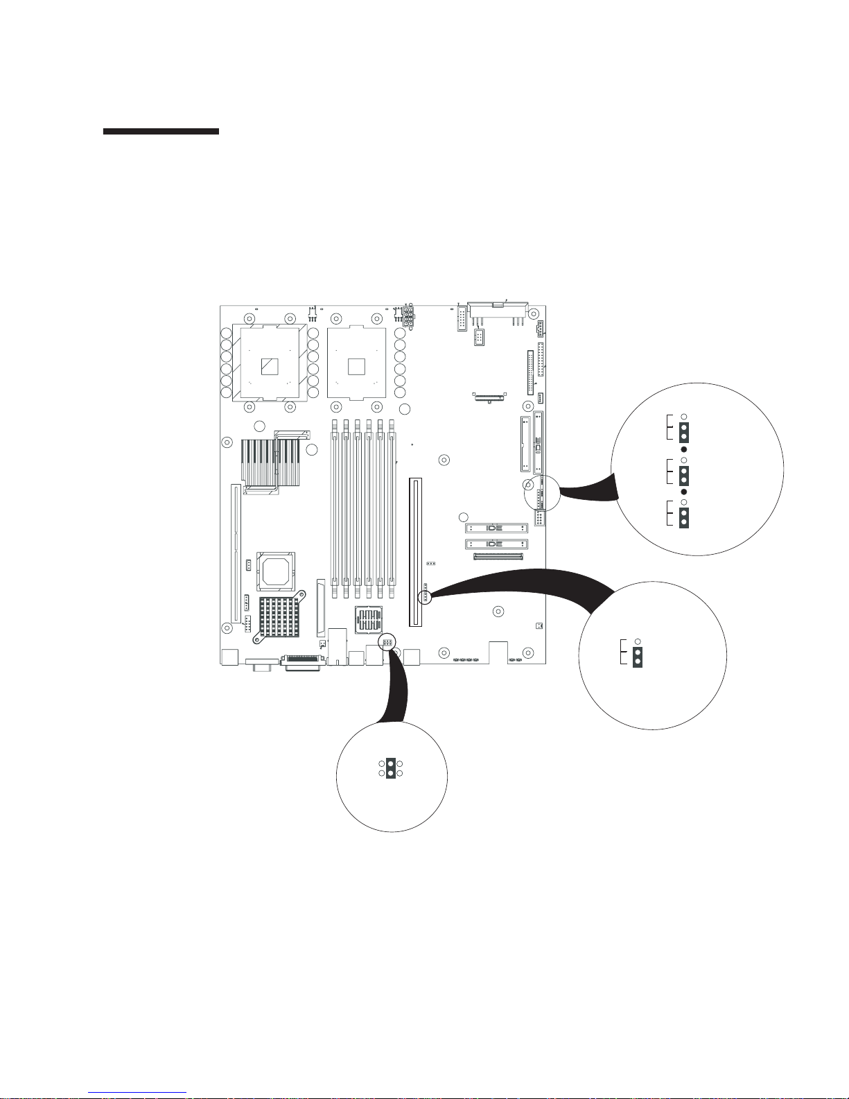
1.4 Setting Main Board Jumpers
You should not normally need to set any of the baseboard jumpers. They are set at
the factory to default positions for optimal operation. However, if you should need
to change them, their locations and functions are shown in Figure 1-1 and Table 1-1.
Recover
Normal
Clear
Normal
Clear
Normal
NN
I
1
2
3
6
4
2
5
3
1
3-4 = DSR
1-2 = DCD
Write En
J5A2
1
2
RCVR\BOOT
3
4
5
6
CLR\PSWD
7
8
9
CLR\CMOS
10
11
BMC BB WENormal
FIGURE 1-1 Main Board Jumper Locations
Chapter 1 Troubleshooting Guidelines 1-5
Page 28

TABLE 1-1 Jumper Function Summary
Designator Jumper Name Action at System Reset
J5A2 RJ-45 Serial COM2 Port
Configuration
CLR\CMOS Clear CMOS If these pins are jumpered, the CMOS settings are cleared.
CLR\PSWD Clear Password If these pins are jumpered, the password is cleared. These
RCVR\
BOOT
BMC BB WE BMC Boot Block Write Enable If these pins are jumpered, BMC boot block is erasable and
BIOS Boot Recovery If these pins are jumpered, the system will attempt BIOS
Configures either a DSR or a DCD signal to the connector.
See “Rear Panel RJ-45 Serial COM2 Connector” in Chapter 2
of the Sun Fire V60x and Sun Fire V65x Server User Guide and
“Setting the Serial COM2 Port Jumper” on page 4-4 in this
document.
These pins should not be jumpered for normal operation.
pins should not be jumpered for normal operation.
recovery. These pins should not be jumpered for normal
operation.
programmable at next reset. These pins should not be
jumpered for normal operation.
1.5 Processor and Heatsink Configurations
This section gives general information regarding the processors and heatsinks used
in the Sun Fire V60x and Sun Fire V65x servers.
1.5.1 Single or Dual Processor Main Boards
The servers run with dual processors or with a single processor. A single processor
system must have a processor installed in processor socket 1 and socket must be
empty. No terminator needs to be installed in processor socket 2 in a single processor
configuration. Processor 1 is the processor nearest the middle of the board.
Processor 2 is located near the edge of the board.
1-6 Sun Fire V60x and Sun Fire V65x Servers—Troubleshooting Guide • November 2003
Page 29

1.5.2 Supported Processors
The server main board supports the 2.8 and 3.06 GHz Intel® Xeon™ self-terminating
processors (see Table 1-2).
TABLE 1-2 Supported Processors and Heatsinks
Marketing Part Number Sun FG Part Number Sun Description
595-6943-01 2.8 GHz Processor with heatsink
595-6944-01 3.06 GHz Processor with heatsink
1.5.3 Heatsinks and Air Ducts
Boxed processors come with the appropriate heatsink and clear plastic air duct for
integration into the server. When installing a heatsink into the server, the heatsink
minus the fan should be used.
1.5.4 Processor Population Order
Processor 1 is the processor closest to the inside of the board and processor 2 is the
processor closer to the corner of the board (see Figure 5-10). The server board is
designed in such a way that it can boot from either processor. If the primary
processor fails to respond in a designated amount of time during POST, the
secondary processor is used to complete the boot-up sequence.
In the event of a single processor configuration, the board halts during the boot
process and displays a message indicating that it is forcing itself to boot from a
potentially bad processor and continues after the user has acknowledged the
message.
For normal operation, it is best if processor 1 is populated first and then processor 2;
however, in the event of a mistake or a failed processor, the server is able to
compensate.
Chapter 1 Troubleshooting Guidelines 1-7
Page 30
1.5.5 Hyper-threading
The Sun Fire V60x and Sun Fire V65x servers feature Hyper-threadingTM capable
processors. Enabling Hyper-threading causes each physical CPU to act as two logical
CPUs. Enabling Hyper-threading on dual-processor Sun Fire V60x and Sun Fire
V65x servers causes the operating system to recognize four distinct processors.
TM
CPU Feature
Hyper-threading
may be enabled or disabled in the system BIOS configuration
menu. Refer to the Sun Fire V60x and Sun Fire V65x Server User Guide, Chapter 4,
for instructions on how to enable or disable this feature.
1.6 Memory Configurations
The server has slots for six 168-pin DIMMs and can support a minimum system
memory configuration of 2 x 128 MB = 256 MB and a maximum system memory
configuration of 6 x 2 GB = 12 GB (for the Sun Fire V65x server) or 6 x 1GB = 6 GB
(for the Sun Fire V60x server) of DDR-266 or later registered compliant SDRAM. The
server supports DIMM sizes of 128 MB, 256 MB, 512 MB, 1 GB, and 2 GB.
The main board supports DDR-266 compliant registered
266 MHz.
Only tested and qualified DIMMs are supported on the main board. Note that all
DIMMs are supported by design, but only fully tested DIMMs will be supported.
The minimum supported DIMM size is 128 MB. Therefore, the minimum main
memory configuration is 2 x 128 MB or 256 MB.
1
ECC DIMMs operating at
The largest size DIMM supported is a 2 GB stacked registered DDR-266 ECC DIMM
based on 512 megabit technology. Therefore, the largest memory size supported is
12 GB.
The memory system on the main board has the following features:
■ ECC single-bit errors are corrected and multiple-bit errors are detected.
■ The maximum memory capacity is 12 GB for the Sun Fire V65x server and 6 GB
for Sun Fire V60x server.
■ The minimum memory capacity is 256 MB
See “Memory” on page 5-9 for details on installing memory.
1. Registered DIMMS are those with an onboard latch that resynchronizes the address/control lines to the
DIMM. These latches are also buffers to allow the Main Board electronics to drive multiple-row devices. It is
most common for ECC SDRAM modules to be registered.
1-8 Sun Fire V60x and Sun Fire V65x Servers—Troubleshooting Guide • November 2003
Page 31

1.7 Problems With SNMP
Unless the dmi2snmp service is configured correctly, failure errors may appear if
and when the service is attempted to be shut down. By default, the dmi2snmp
service is not configured robustly enough to be started/stopped successfully.
Note – The dmisnmp2 service is not supported in the SOlaris OS.
Chapter 1 Troubleshooting Guidelines 1-9
Page 32

1.8 Problems With Initial System Startup
Problems that occur at initial system startup are usually caused by incorrect
installation or configuration. Hardware failure is a less frequent cause.
1.8.1 Checklist
■ Are all cables correctly connected and secured?
■ Is the power cord properly inserted and fully seated?
■ Are there any Baseboard Management Controller (BMC) beep codes? You may
have to listen carefully two or three times to hear them. See “POST Error Beep
Codes” on page 3-19 for beep code details.
■ Is the BMC running? Try pressing the ID button on the front panel. If the blue ID
LED fails to illuminate, the BMC is not responding.
■ Are the cables going to the front panel board installed and seated properly (check
the front panel cable, the USB cable, and the 100-pin flex cable).
■ Are the processors fully seated in their sockets on the server board?
■ Are all add-in PCI boards fully seated in their slots on the server board?
■ Are all jumper settings on the server board correct?
■ Are all jumper and switch settings on add-in boards and peripheral devices
correct? To check these settings, refer to the manufacturer’s documentation that
comes with them. If applicable, ensure that there are no conflicts—for example,
two add-in boards sharing the same interrupt.
■ Are all DIMMs installed correctly?
■ Are all peripheral devices installed correctly?
■ If the system has a hard disk drive, is it properly formatted or configured?
■ Are all device drivers properly installed?
■ Are the configuration settings made in BIOS Setup correct?
■ Is the operating system properly loaded? Refer to the operating system
documentation.
■ Did you press the system power on/off switch on the front panel to turn the
server on (power on light should be lit)?
■ Is the system power cord properly connected to the system and plugged into a
NEMA 5-15R outlet for 100-120 V or a NEMA 6-15R outlet for 200-240V?
■ Is AC power available at the wall outlet?
■ Are there any POST LEDs illuminated? If so check “Power-On Self Test (POST)”
on page 3-15.
■ Are there any POST beep codes? If so check “POST Error Beep Codes” on page 3-19
1-10 Sun Fire V60x and Sun Fire V65x Servers—Troubleshooting Guide • November 2003
Page 33

1.9 Problems With New Application
Software
Problems that occur when you run new application software are usually related to
the software. Faulty equipment is much less likely, especially if other software runs
correctly.
Use this checklist:
■ Does the system meet the minimum hardware requirements for the software? See
the software documentation.
■ Is the software an authorized copy? If not, get one; unauthorized copies often do
not work.
■ If you are running the software from a diskette, is it a good copy?
■ If you are running the software from a CD-ROM disk, is the disk scratched or
dirty?
■ If you are running the software from a hard disk drive, is the software correctly
installed? Were errors ignored while installing the software? If so, address these
errors and try re-installation.
■ Were all necessary procedures followed and files installed?
■ Are the correct device drivers installed?
■ Is the software correctly configured for the system?
■ Are you using the software correctly?
If the problems persist, contact the software vendor’s customer service
representative.
Chapter 1 Troubleshooting Guidelines 1-11
Page 34

1.10 Problems After the System Has Been
Running Correctly
Problems that occur after the system hardware and software have been running
correctly often indicate equipment failure. Many situations that are easy to correct,
however, can also cause such problems.
Use this checklist:
■ If you are running the software from a diskette, try a new copy of the software.
■ If you are running the software from a CD-ROM disk, try a different disk to see if
the problem occurs on all disks.
■ If you are running the software from a hard disk drive, try running it from a
diskette. If the software runs correctly, there may be a problem with the copy on
the hard disk drive. Reinstall the software on the hard disk, and try running it
again. Make sure all necessary files are installed.
■ If the problems are intermittent, there may be a loose cable, dirt in the keyboard
(if keyboard input is incorrect), a marginal power supply, or other random
component failures.
■ If you suspect that a transient voltage spike, power outage, or brownout might
have occurred, reload the software and try running it again. When voltage spikes
or brownouts occur, symptoms include a flickering video display, unexpected
system reboots, and the system not responding to user commands.
Note – If you are getting random errors in your data files, they may be getting
corrupted by voltage spikes on your power line. If you are experiencing any of the
above symptoms that might indicate voltage spikes on the power line, install a surge
suppressor between the power outlet and the system power cord.
1-12 Sun Fire V60x and Sun Fire V65x Servers—Troubleshooting Guide • November 2003
Page 35

CHAPTER
2
Troubleshooting Specific Problems
This chapter instructs you on how to solve specific problems with the Sun Fire V60x
and Sun Fire V65x servers. It contains the following sections:
■ “Preparing the System for Diagnostic Testing” on page 2-1
■ “Specific Problems and Corrective Actions” on page 2-2
■ “Other Problems” on page 2-20
■ “General Board and Feature Issues” on page 2-21
2.1 Preparing the System for Diagnostic
Testing
Caution – Turn off devices before disconnecting cables. Before disconnecting any
peripheral cables from the system, turn off the system and any external peripheral
devices. Failure to do so can cause permanent damage to the system and/or the
peripheral devices.
1. Turn off the system and all external peripheral devices. Disconnect all of them
from the system, except the keyboard and video monitor.
2. Make sure the system power cord is plugged into a properly grounded AC outlet.
3. Make sure your video display monitor and keyboard are correctly connected to
the system. Turn on the video monitor. Set its brightness and contrast controls to
at least two thirds of their maximum ranges (see the documentation supplied with
your video display monitor).
4. If the operating system normally loads from the hard disk drive, make sure there
is no diskette in drive A. Otherwise, place a diskette containing the operating
system files in drive A.
2-1
Page 36

5. Turn on the system. If the power LED does not light, see “Power LED Does Not
Light” on page 2-9.
6. If errors are encountered, power off the system, remove all add-in cards, and turn
the power back on.
2.2 Specific Problems and Corrective
Actions
This section provides possible solutions for the specific problems listed in Table 2-1.
TABLE 2-1 Index to Problems
Problems Reference
“Problems Starting Up” page 2-3
“Power LED Does Not Light” page 2-9
“Video Problems” page 2-10
“System Cooling Fans Do Not Rotate Properly” page 2-12
“Disk Drive Activity Light Does Not Light” page 2-12
“CD-ROM Drive Activity Light Does Not Light” page 2-12
“Cannot Connect to a Server” page 2-13
“Problems with Network” page 2-13
“Problems with Application Software” page 2-14
“Bootable CD-ROM Is Not Detected” page 2-14
“Memory Configuration Errors” page 2-15
Try the solutions in the order given. If you cannot correct the problem, contact your
service representative or authorized dealer for help.
2-2 Sun Fire V60x and Sun Fire V65x Servers—Troubleshooting Guide • November 2003
Page 37

2.2.1 Problems Starting Up
If the server does not start up properly, use the information in this section to
diagnose problems.
2.2.1.1 Server Does Not Power On
If the server does not power on, check the following:
■ Does the main server board have power? Open the chassis lid and check the 5V
Standby LED on the baseboard to see if it is illuminated. If your server is plugged
in, this LED should be green. See Figure 3-5, “Fault and Status LEDs on the Server
Board,” on page 3-13 for the location of this LED.
■ Check the power cord connection. The Sun Fire V65x server allows the use of two
power supplies, and the system will not power on if one power cord is used and
it is plugged into the wrong power connector.
■ Is the flex circuit cable, labeled Floppy/FP/IDE, properly seated on the baseboard
and backplane? And are any retention clips used to hold the cable in place
properly installed?
■ If you are using a Sun Fire V60x server, make sure that the power supply is fully
seated in the power distribution board connector.
■ Remove all add-in cards and see if the server boots using just the on-board
components. If the server boots successfully, add the cards back in one at a time
with a reboot after each addition to see if you can isolate a suspect card.
■ Remove and reseat the memory modules. Ensure that you have properly
populated the memory modules. On the main board, memory is populated in
pairs. See “Memory” on page 5-9 for memory module installation and placement.
Refer to the silkscreen on the main board for proper memory module placement.
Try using memory modules from a known, compatible, server.
■ Remove the processor(s) and reseat as a last resort.
Caution – Removing and replacing the processors is not recommended and should
only be done as a last resort. This is a procedure that should be attempted by Sun
qualified service personnel. Instructions for removing and replacing processors are
given in the section titled “Replacing a Server CPU and Heatsink” on page 5-16.
Chapter 2 Troubleshooting Specific Problems 2-3
Page 38

2.2.1.2 Front Panel is Unresponsive and Video is Disabled
If the front panel is unresponsive to any pushbuttons you press, and video is
disabled, it could be that the front panel is locked. By default, front panel locking is
disabled; however, it is possible to enable front panel locking through the BIOS
setup. To do this, an administrative password must be set using Security > Set
Admin Password.
When the password is set, the front panel, mouse, and keyboard are locked after a
timeout expires. The video is also blanked. The purpose of this is to prevent
unauthorized access to a server by someone who plugs in a keyboard and video
monitor. Access is regained simply by using the keyboard to type the password.
Note – A corded PS/2 keyboard (not a wireless one) must be plugged into the
keyboard/mouse connector at the back of the server. When the front panel is locked,
the lights on the keyboard flash, but the server is still fully functional.
2-4 Sun Fire V60x and Sun Fire V65x Servers—Troubleshooting Guide • November 2003
Page 39

2.2.1.3 Server Beeps at Power On or When Booting
The server indicates problems with “beep codes” during Power-On Self Test (POST)
in the event there is no displayed video. A complete list of beep codes is given in
“POST Error Beep Codes” on page 3-19.
The following beep codes identify system events during POST in case video fails to
display.
TABLE 2-2 Bootup Beep Codes
Beeps Reason
1 One short beep before boot (normal, not an error)
1-2 Search for option ROMs. One long beep and two short beeps on checksum
failure.
1-2-2-3 BIOS ROM checksum
1-3-1-1 Test DRAM refresh
1-3-1-3 Test 8742 keyboard controller
1-3-3-1 Auto size DRAM. System BIOS stops execution here if the BIOS does not
detect any usable memory DIMMs.
1-3-4-1 Base RAM failure. BIOS stops execution here if entire memory is bad.
2-1-2-3 Check ROM copyright notice.
2-2-3-1 Test for unexpected interrupts.
1-5-1-1 FRB failure (processor failure)
1-5-2-2 No processors installed
1-5-2-3 Processor configuration error (for example, mismatched VIDs).
1-5-2-4 Front-side bus select configuration error (for example, mismatched BSELs)
1-5-4-2 Power fault
1-5-4-3 Chipset control failure
1-5-4-4 Power control failure
2.2.1.4 Some Hard Drives Do Not Show Up During POST
The server board includes an embedded Adaptec AIC-7902 controller, which
provides dual Ultra320 Low Voltage Differential SCSI (LVDS) channels.
The SCSI bus is terminated on the server board with active terminators that cannot
be disabled. The onboard device must be at one end of the bus. The device at the
other end of the cable must also be terminated. LVDS devices generally do not have
Chapter 2 Troubleshooting Specific Problems 2-5
Page 40

termination built in and need to have a termination source provided. Non-LVDS
devices generally are terminated through a jumper or resistor pack on the device
itself.
In the event that there is a problem with hard disk drives being recognized, check
the following:
■ Are you using third party SCSI adapters? System memory limitations limit the
number and size of option ROMs in the system. If you place too many adapters or
adapters that take up too much space in memory, they may not install and show
the hard drives connected to them.
■ If the Option ROM scan for your card or the onboard SCSI device has been
disabled, no drives connected to that device will show up during POST.
■ Verify that the device power cable is firmly connected.
■ Check your SCSI ID numbers. SCSI devices must have their own unique ID on the
SCSI bus. This number must be set with jumpers on the device. The ID number
should be set starting at 0 and must be set lower than 8 if booting from the drive.
■ Check for proper termination on the SCSI bus.
Note – Note: In the unlikely event that the server does not boot, it may be that the
server did not recognize the SCSI drive(s). If this happens, try booting again.
■ If you mix internal LVDS SCSI hard drives with different bus speeds in a single
system, you may encounter problems. You may need to modify the SCSI Device
Configuration settings to allow this type of configuration.
■ You may encounter issues when booting from internal SCSI drives when an
external SCSI device or an external SCSI array has been added.
To boot the system using internal drives, the SCSI BIOS settings may need to be
modified for each channel. See example below:
1. To go into the SCSI BIOS settings, press the keys Ctrl + A (at POST, during the
SCSI initialization phase).
2. Once in the SCSI BIOS, select External Channel A AIC-7902 A slot at 00:04:07:00,
then select the following: Configure/View SCSI Controller Settings and Advanced
Configuration.
3. In the Advanced Configuration menu, go to SCSI Controller Int 13 Support and
select one of the Disabled options.
4. In the SCSI BIOS settings screen, select Internal Channel B AIC-7902 B at slot
00:04:07:01, then select the following: Configure/View SCSI Controller Settings
and Advanced Configuration.
5. In the Advanced Configuration menu, go to SCSI Controller Int 13 Support and
select the Enabled option if it is not already enabled.
6. Save the settings before exiting the menu.
2-6 Sun Fire V60x and Sun Fire V65x Servers—Troubleshooting Guide • November 2003
Page 41

2.2.1.5 Server Starts Booting Automatically at Power On
The server board saves the last known power state in the event of a power failure. If
you remove power before powering down the system using the power switch on the
front panel, your system might automatically attempt to restore itself back to the
state it was in after you restore power.
You can configure how you would like your server system to react when power is
restored in the BIOS set-up (Security menu). See “BIOS Setup Utility <F2>” on
page 4-9. You can have the server remain off or return to the last known power state.
■ Please keep in mind that unplugging the system or flipping a switch on the
power strip both remove power.
■ Follow the correct power removal sequence (make sure the system has shut down
before removing the power cord).
2.2.1.6 Power-On Self-Test (POST)
Each time you turn on the system, the BIOS begins execution of POST. POST
discovers, configures, and tests the processors, memory, keyboard, and most
installed peripheral devices. The time needed to test memory depends on the
amount of memory installed. POST is stored in flash memory.
To execute and monitor POST:
1. Turn on your video monitor and system. After a few seconds, POST begins to run
and displays a splash screen.
2. While the splash screen is displayed:
■ Press <F2> to enter the BIOS Setup (see “BIOS Setup Utility <F2>” on page 4-9“)
OR
■ Press <Esc> to view POST diagnostic messages and change the boot device
priority for this boot only (see “Choose Boot Device <ESC>” on page 4-13.
OR
■ If the Service Partition is installed, press <F4> to run the System Setup Utility (see
“Using the Service Partition Menu” on page 4-24)
3. If you do not press <F2> or <Esc> or <F4> and do NOT have a device with an
operating system loaded, the boot process continues and the system beeps once.
The following message is displayed:
Operating System not found
4. At this time, pressing any key causes the system to attempt a reboot. The system
searches all removable devices in the order defined by the boot priority.
Chapter 2 Troubleshooting Specific Problems 2-7
Page 42

During POST, the server BIOS presents screen messages to indicate error conditions.
POST also provides beep codes to give you audible clues regarding the performance
and operation of the server when there is no video display that can present error
messages. In addition, a set of four bi-color diagnostic LEDs is located on the back
edge of the server main board. These LEDs are active during POST and indicate the
state of the server. Each of the four LEDs can have one of four states: Off, Green,
Red, or Amber. See “Power-On Self Test (POST)” on page 3-15 for a complete
description of the screen messages, beep codes, and diagnostic LEDs.
2.2.1.7 Verifying Proper Operation of Key System LEDs
As POST determines the system configuration, it tests for the presence of each mass
storage device installed in the system. As each device is checked, its activity light
should turn on briefly. Check to see if the disk drive activity light for each drive
turns on briefly. If not, see “Disk Drive Activity Light Does Not Light” on page 2-12.
2.2.1.8 Confirming Loading of the Operating System
Once the system boots up, an operating system prompt similar to the one shown
below appears on the screen (this example is for Linux):
Linux release x.x
Kernel 2.4.931enterprise on an i386
<hostname> login:
The prompt varies according to the operating system. If the operating system
prompt does not appear, see “Loading the Operating System” on page 4-16 or
“Recovering the BIOS” on page 4-53, or “Processor and Heatsink Configurations” on
page 1-6.
2.2.1.9 KVM (PS/2 Keyboard-Video-Mouse) Unit Causes System To
Hang During POST
Some KVM switches may cause intermittent problems during Power-On Self Test
(POST). Possible issues are as follows:
■ The system may not respond to keyboard or mouse inputs.
■ The system may hang, causing the watchdog timer to expire. This in turn causes
a FRB-2 (Fault Resilient Booting) event. By default, if a FRB-2 event occurs (on
redundant processor systems), the Boot-Strap-Processor will be disabled on the
next boot.
2-8 Sun Fire V60x and Sun Fire V65x Servers—Troubleshooting Guide • November 2003
Page 43

To return a system with redundant processors to normal operation after an FRB2
event, follow the instructions below:
1. Reset or turn on the system.
2. Press the F2 key to select SETUP as soon as the option appears on the screen.
3. Once in the main page of the SETUP menu, use the arrow keys to select Processor
Settings then press Enter.
4. In the Processor Settings screen, select Processor Retest then select Enabled.
5. Press the F10 function key to exit the SETUP menu and save changes.
The system will then re-test both processors to make sure they are in working
condition and bring both processors back to normal operation.
Note – The ‘Processor Retest’ feature will return to its default ‘Disabled’ condition,
after this cycle is complete.
2.2.2 Power LED Does Not Light
Check the following:
■ Is the system operating normally? If so, the power LED is probably defective or
the cable from the front panel to the server board is loose.
■ Are there other problems with the system? If so, check the items listed under
“System Cooling Fans Do Not Rotate Properly” on page 2-12.
If all items are correct and problems persist, contact your service representative or
authorized dealer for help.
Chapter 2 Troubleshooting Specific Problems 2-9
Page 44

2.2.3 Video Problems
This section gives help on how to isolate and solve video problems.
2.2.3.1 No Video Appears on the Screen
Check the following:
■ The server board accommodates two processors. If only one processor is installed,
it must be placed in the CPU 1 socket. The system will not boot if only one
processor is installed and it is in the CPU 2 socket.
■ Are there any beeps coming from the board and is the floppy drive being
accessed? If so, your system may have been put in the BIOS recovery mode. This
mode is used to reflash the BIOS in the event it gets corrupted. To enter this
mode, the RCVR\BOOT jumper located along the edge of the board must be set
on the two pins nearest the front of the server. For normal operation, this jumper
must be set on the two pins nearest the back of the server. See Figure 1-1 on
page 1-5 for the location of the RCVR\BOOT jumper.
■ Make sure the monitor is turned on and the video cable is plugged in completely.
If you are using a switch box to share a monitor between multiple servers, ensure
that you have switched to the proper server.
■ Is a video cable plugged into the front panel video connector? If so, the rear video
connector will be disabled.
■ Is there an add-in PCI video card? If so, on-board video will be disabled.
■ Remove all add-in cards and retry booting with just the on-board components. If
this is successful, try plugging in the add-in boards one at a time with a reboot
between each addition to isolate a suspect card.
■ As a last resort, remove and reseat memory modules and processors. Try using
memory and processors from a known working system.
Caution – Removing and replacing the processors is not recommended and should
only be done as a last resort. This is a procedure that should be attempted by Sun
qualified service personnel. Instructions for removing and replacing processors are
given in the section titled “Replacing a Server CPU and Heatsink” on page 5-16.
■ Video can be disabled on the server by means of the BIOS setup. If you are using
an add-in video card, make sure your monitor is plugged into the add-in video
card. If you suspect that your video controller may be disabled through the BIOS
setup, you can attach to the system through a server management connection
(either through the serial COM2 port or the LAN connector) and redirect the BIOS
setup screen to a remote console to check. For details on how to do this, refer to
“Configuring an External Serial Console” on page 4-17.
2-10 Sun Fire V60x and Sun Fire V65x Servers—Troubleshooting Guide • November 2003
Page 45

If the preceding steps do not solve the problem, check the following:
■ Is the keyboard functioning? Check to see that the “Num Lock” light is
functioning.
■ Is the video monitor plugged in and turned on?
■ Are the brightness and contrast controls on the video monitor properly adjusted?
■ Are the video monitor switch settings correct?
■ Is the video monitor signal cable properly installed?
■ Is the onboard video controller enabled?
If you are using an add-in video controller board, do the following:
1. Verify that the video controller board is fully seated in the server board connector.
2. Reboot the system for changes to take effect.
3. If there are still no characters on the screen after you reboot the system and POST
emits a beep code, write down the beep code you hear. This information is useful
for your service representative.
4. If you do not receive a beep code and characters do not appear, the video display
monitor or video controller may have failed. Contact your service representative
or authorized dealer for help.
2.2.3.2 Xserver Has Not Started
The typical reason that Xserver has not been started is that it is not set up to start by
default. Xserver is installed by default in the Solaris OS.
2.2.3.3 Characters Are Distorted or Incorrect
Check the following:
■ Are the brightness and contrast controls properly adjusted on the video monitor?
See the manufacturer’s documentation.
■ Are the video monitor signal and power cables properly installed?
If the problem persists, the video monitor may be faulty or it may be the incorrect
type. Contact your service representative or authorized dealer for help.
Chapter 2 Troubleshooting Specific Problems 2-11
Page 46

2.2.4 System Cooling Fans Do Not Rotate Properly
If the system cooling fans are not operating properly, system components could be
damaged.
Check the following:
■ Is AC power available at the wall outlet?
■ Is the system power cord properly connected to the system and the wall outlet?
■ Did you press the power button?
■ Is the power on light illuminated?
■ Have any of the fan motors stopped (use the server management subsystem to
check the fan status)?
■ Are the fan power connectors properly connected to the server board?
■ Is the cable from the front panel board connected to the server board?
■ Are the power supply cables properly connected to the server board?
■ Are there any shorted wires caused by pinched cables or power connector plugs
forced into power connector sockets the wrong way?
If the switches and connections are correct and AC power is available at the wall
outlet, contact your service representative or authorized dealer for help.
2.2.5 Disk Drive Activity Light Does Not Light
Check the following:
■ Are the disk drive power and signal cables properly installed?
■ Are all relevant switches and jumpers on the disk drive set correctly?
■ Is the disk drive properly configured?
■ Is the disk drive activity light always on? If so, the signal cable may be plugged in
incorrectly.
Use the Setup Utility to make sure that the disk drive is enabled.
If the problem persists, there may be a problem with the disk drive, server board, or
drive signal cable. Contact your service representative or authorized dealer for help.
2.2.6 CD-ROM Drive Activity Light Does Not Light
Check the following:
■ Are the power and signal cables to the CD-ROM drive properly installed?
■ Are all relevant switches and jumpers on the drive set correctly?
■ Is the drive properly configured?
■ Is the onboard IDE controller enabled?
■ Is the flex cable between the server board and the backplane installed properly?
2-12 Sun Fire V60x and Sun Fire V65x Servers—Troubleshooting Guide • November 2003
Page 47

■ Verify that the CD-ROM drive works correctly in another system.
■ Check to see if the BIOS detects the CD-ROM during bootup.
■ Check the BIOS setup menu to see if the CD-ROM is present and set up as a boot
device.
2.2.7 Cannot Connect to a Server
Check the following:
■ Make sure you are using the onboard network controller drivers that are shipped
on the installation CDs.
■ Make sure the driver is loaded and the protocols are bound.
■ Make sure the network cable is securely attached to the connector at the system
back panel. If the cable is attached but the problem persists, try a different cable.
■ Make sure the hub port is configured for the same duplex mode as the network
controller.
■ Check with your LAN administrator about the correct networking software that
needs to be installed.
■ If you are directly connecting two servers (no hub), you will need a crossover
cable (see your hub documentation for more information on crossover cables).
■ Check the network controller LEDs that are visible through an opening at the
system back panel.
2.2.8 Problems with Network
If the server hangs when the drivers are loaded:
■ Change the PCI BIOS interrupt settings.
If diagnostics pass, but the connection fails:
■ Make sure the network cable is securely attached.
The Activity LED does not light:
■ Make sure the network hub has power.
■ For Linux, make sure that you are using the e1000 drivers that are part of a 2.4.18-
24.7.x or 2.4.18-24.8.x (or later) kernel. If using an older kernel, use the e1000
drivers on the SunFire Resource CD.
If the controller stopped working when an add-in adapter was installed:
■ Make sure the cable is connected to the port from the onboard network controller.
■ Make sure your PCI BIOS is current.
■ Make sure the other adapter supports shared interrupts. Also, make sure your
operating system supports shared interrupts.
■ Try reseating the add in adapter.
Chapter 2 Troubleshooting Specific Problems 2-13
Page 48

If the add-in adapter stopped working without apparent cause:
■ Try reseating the adapter first; then try a different slot if necessary.
■ The network driver files may be corrupt or deleted. Delete and then reinstall the
drivers.
■ Run the diagnostics.
Note – Disconnecting an Ethernet cable from Network 2 may interrupt network
connectivity on other network interfaces. Run the following commands to restore
connectivity to other connected network interfaces:
# /etc/rc.d/init.d/network stop
# /etc/rc.d/init.d/network start
2.2.9 Problems with Application Software
If you have problems with application software, do the following:
■ Verify that the software is properly configured for the system. See the software
installation and operation documentation for instructions on setting up and using
the software.
■ Try a different copy of the software to see if the problem is with the copy you are
using.
■ Make sure all cables are installed correctly.
■ Verify that the server board jumpers are set correctly. See “Setting Main Board
Jumpers” on page 1-5.
■ If other software runs correctly on the system, contact your vendor about the
failing software.
If the problem persists, contact the software vendor’s customer service
representative for help.
2.2.10 Bootable CD-ROM Is Not Detected
Check the following:
■ Is the BIOS set to allow the CD-ROM to be the first bootable device?
■ Check cable connections.
■ Verify CD is bootable in another known good CD-ROM drive, especially if the CD
is a copy.
2-14 Sun Fire V60x and Sun Fire V65x Servers—Troubleshooting Guide • November 2003
Page 49

2.2.11 Memory Configuration Errors
If you have added, removed, or replaced a DIMM, and you encounter memory
configuration errors during power-on self test (POST), do the following to clear the
errors.
Note – If the errors you see are DIMM population errors 8508, 8509 or 850A, you
must reorder the DIMMs. See “Memory DIMM Population Order” on page 2-15 for
more information.
1. Reset or turn on system.
2. Press the F2 key to select SETUP as soon as the option appears on the screen.
3. Once in the main page of the SETUP menu, use the arrow keys to select Advanced
menu.
4. In the Advanced screen, select Memory Configuration option then press Enter.
5. In the Memory Configuration screen, select Memory Retest then select Enabled.
6. Press the F10 function key to exit the SETUP menu and save changes.
Note – The Memory Retest feature will return to its default Disabled condition after
the memory test cycle is complete.
2.2.11.1 Memory DIMM Population Order
If you install modules with mixed memory sizes in your Sun Fire V60x or V65x
server, you must install the single-wide memory modules (256 MB or 512 MB) in the
lower numbered slots and the double-wide memory modules (1 GB or 2 GB) in the
higher numbered slots.
Chapter 2 Troubleshooting Specific Problems 2-15
Page 50

If single-wide modules are installed in slots with higher numbers than double-wide
modules, you will encounter one of the following messages during POST while the
system is booting up:
Error 8508: A DIMM population error has been detected. Please
swap DIMM pair 1A/1B with DIMM pair 2A/2B.
Error 8509: A DIMM population error has been detected. Please
swap DIMM pair 1A/1B with DIMM pair 3A/3B.
Error 850A: A DIMM population error has been detected. Please
swap DIMM pair 2A/2B with DIMM pair 3A/3B.
When you see these messages during POST, shut down the system and reinstall the
DIMMs so that all of the single-wide DIMMs are in lower numbered slots than the
double-wide DIMMs.
Refer to “Memory” on page 5-9 for more information on how to correctly replace the
DIMMs.
2.2.11.2 Soft Reboot Errors
Note – This note applies if you are using BIOS Release 2.0 v1161 or earlier. This bug
has been fixed in the BIOS release 5.0 (v1175).
After issuing a Soft Reboot, there is very small probability that the memory will not
reset correctly. If the memory does not reset correctly, the system will log an error in
the System Event Log, disable the bank of memory that did not reset correctly, and
halt. Upon rebooting, the system will either appear to have no memory installed or
will BOOT with one of the memory banks disabled.
If this occurs, perform one of the following procedures to reset the system,
depending on how many DIMMs are in your system.
For Systems With Four or More DIMMs
1. Turn on the system.
2. Press the F2 key to select SETUP when the option appears on the screen.
3. In the main page of the SETUP menu, use the arrow keys to select the Advanced
menu.
2-16 Sun Fire V60x and Sun Fire V65x Servers—Troubleshooting Guide • November 2003
Page 51

4. In the Memory Configuration screen, select Memory Retest, then select Enabled.
5. Press the F10 key to exit the SETUP menu and save the changes.
The system will now boot correctly.
For Systems With Only Two DIMMs
1. Open the top cover and move the existing two DIMMs from their current bank to
one of the other two banks.
2. Power on the system.
3. Press the F2 key to select SETUP when the option appears on the screen.
4. Once in the main page of the SETUP menu, use the arrow keys to select the
Advanced menu.
5. In the Memory Configuration screen, select Memory Retest, then select Enabled.
6. Press the F10 key to exit the SETUP menu and save the changes.
The system reboots automatically.
7. Power off the system.
8. Move the DIMMs back to their original location.
Note – If this step is skipped the following error messages may appear on the
screen and on the System Event Log:
Error 8502: Bad or missing memory in Slot 1A
Error 8506: Bad or missing memory in Slot 1B
9. Replace the top cover.
10. Power on the system.
The system will boot correctly on subsequent reboots.
Note – The Memory Retest feature returns to its default Disabled condition after the
memory test cycle is complete.
Chapter 2 Troubleshooting Specific Problems 2-17
Page 52

2.2.11.3 Faulty Memory DIMMs
Note – This note applies if you are using BIOS release 5.0 (v1175) or later.
If you don't add, remove or replace any memory DIMM modules and you encounter
memory errors during POST after issuing a soft reset, hard reset or powering on the
system, then the BIOS is detecting faulty memory DIMM modules in the system
during memory test in POST.
The BIOS will log an error in the System Event log, disable the memory bank that
contains the faulty memory DIMM modules and reset the system. Upon rebooting,
the system will either appear to have no memory installed or will boot with one of
the memory banks disabled.
If this occurs, perform one of the following procedures to reset the system after
replacing the faulty memory DIMM modules. Choose the procedure that
corresponds with how many DIMMs are in your system.
For Systems With Four or More DIMMs
1. Turn on the system.
2. Boot the system with the Diagnostics CD in the CD-ROM drive to enter the
Diagnostic CD menu or press the F4 key at the initial bootup screen to enter the
Service Partition menu.
3. Invoke the SEL manager.
a. Use the arrow key to select the System Utility menu and press Enter.
b. Choose the Run System Setup Utility menu.
c. Press any key when prompted.
d. Choose the SEL Manager option.
4. View the SEL Manager listing to determine which faulty DIMM is detected by the
BIOS.
5. Choose the Exit option from the File menu of the SEL manager.
6. Exit out of the SSU menu and Diagnostics CD main menu.
7. Turn off the system.
8. Open the top cover.
2-18 Sun Fire V60x and Sun Fire V65x Servers—Troubleshooting Guide • November 2003
Page 53

9. Remove the faulty DIMM and replace it with the good DIMM (read the silkscreen
on the motherboard for the DIMM position).
Refer to the Sun Fire V60x and Sun Fire V65x Server User Guide (817-2023-xx) for
information on how to correctly replace the DIMMs.
Note – Make sure to replace only the faulty DIMM as indicated in the SEL Manager.
10. Replace the top cover.
11. Power on the system.
12. Press the F2 key to select SETUP when the option appears on the screen.
13. In the main page of the SETUP menu, use the arrow keys to select the Advanced
Menu.
14. In the Memory Configuration screen, select Memory Retest and select Enabled.
15. Press the F10 key to exit the SETUP menu and save the changes.
16. The system will now boot correctly with no memory errors.
For Systems With Only Two DIMMs
1. When you turn on the system, the BIOS will issue a sequence of beeps to indicate
a memory error detected in POST and the system will not boot (no video will be
displayed on the screen either).
2. Turn off the system.
3. Remove the two faulty DIMMs from Slot 1A and Slot 1B.
4. Insert two good DIMMs in Slot 2A and Slot 2B.
Refer to the Sun Fire V60x and Sun Fire V65x Server User Guide (817-2023-xx) for
information on how to correctly replace the DIMMs.
5. Power on the system.
6. Press the F2 key to select SETUP when the option appears on the screen.
7. In the main page of the SETUP menu, use the arrow keys to select the Advanced
Menu.
8. In the Memory Configuration screen, select Memory Retest and select Enabled.
9. Press the F10 key to exit the SETUP menu and save the changes.
10. The system reboots automatically.
Chapter 2 Troubleshooting Specific Problems 2-19
Page 54

11. Power off the system.
12. Move the DIMMs back to Slot 1A and Slot 1B.
Note – Note: If this step is skipped the following error messages may appear on the
screen and on the System Event Log:
Error 8502: Bad or missing memory in slot 1A
Error 8506: Bad or missing memory in slot 1B
13. Replace the top cover.
14. Power on the system.
The system will boot correctly on subsequent reboots.
Note – The Memory Retest feature returns to its default Disabled condition after the
memory test cycle is complete.
2.3 Other Problems
If the preceding information does not fix the problem with your server, try the
following:
■ Update the firmware files to the latest version.
■ The files used include BIOS, BMC, FRU/SDR, and HSC.
■ Clear the CMOS upon completion. This can be accomplished by moving the
clear CMOS jumper or by holding down the reset button for 4 seconds and at
the end of 4 seconds, while holding down the reset button, press the power
button then release both at the same time.
■ Update files can be downloaded from the Sun support web site
■ Download and apply the latest drivers used in your installation. These drivers
may include video, network adapter, SCSI, and chipset.
■ Check for proper processor installation. Systems with a single processor must
have the CPU installed in CPU socket 1. If two processors are installed, the
processors must be of the same speed and voltage (and within one stepping). Do
not attempt to over clock the processors or other components on this system.
Over clocking is generally not possible and may damage components and void
the warranty of your server board and your boxed or tray processor.
■ Memory must be of the approved type and be properly seated.
2-20 Sun Fire V60x and Sun Fire V65x Servers—Troubleshooting Guide • November 2003
Page 55
■ Verify that all chassis and power supply fans are properly installed and
functioning.
■ Approved heat sinks must be properly installed on the processors. Do not attempt
to run the processors without a heat sink for even a few moments.
■ If the system is running slowly or you receive a processor error message, enter
BIOS setup and enable processor retest. This test will be run only on the next
reboot and will retest the processors and bring them back online if marked failed.
■ When using multiple PCI adapter cards in a PCI riser with more than one slot,
populate the slots from the bottom up.
2.4 General Board and Feature Issues
1. Why is the serial COM2 port implemented through an RJ-45 connector?
The server board is designed specifically for the High Density Rack Mount
(HDRM) environment. Therefore, several HDRM features, such as a high density
serial port have been implemented. The intention for the rear RJ-45 serial port is
for serial concentrator applications. Several serial concentrators on the market are
accessed through an RJ-45 serial port. In order to accommodate both serial
concentrator communication standards and standard modem/UPS type
communication standards, there are a set of jumpers located directly behind the
RJ-45 serial connector on the baseboard. These jumpers can be used to route the
DSR signal to pin 7 on the connector for serial concentrator type implementations
or have the DCD signal routed to that pin for modem/UPS type implementations.
See “Setting the Serial COM2 Port Jumper” on page 4-4 for details.
2. How do I disable the integrated components?
Onboard controllers can be disabled through the server board BIOS setup. To
enter BIOS setup, press F2 when prompted during the boot up process.
3. What jumpers are available and how should they be set?
There are three headers on the main jumper block on the server board at the left
edge of the board. Jumpers at this location are available for the following
functions:
■ Recovery Boot
■ Password Clear
■ CMOS Clear
An additional jumper is available for BMC Write Protect (WP). It is located
towards the rear of the main board, at the left side of the full-depth PCI slot.
For normal operation, these jumpers should be left in their default position as
shipped from the factory.
Chapter 2 Troubleshooting Specific Problems 2-21
Page 56

4. What processors are supported on the main board?
The server board supports the Intel Xeon™ processor with 512K cache.
5. What heatsink should I use?
The boxed processor is available in two basic package configurations. It is
available packaged for the Sun Fire V60x server 1U chassis implementation and is
bundled with a low profile 1U copper heatsink and air duct. It is also available for
the Sun Fire V65x server. This package is bundled with a full-height heat sink and
processor air duct. You must select the proper package for your chassis type and
configuration. For integration into the Sun Fire V60x server, the 1U version of the
packaged processor must be used. For the Sun Fire V65x server chassis, the 2U/
Pedestal version of the processor package must be used. Do not attempt to use the
1U version of the packaged processor with the Sun Fire V65x server as this chassis
is designed to provide proper airflow through a plastic shroud and through the
fins of the full height heatsink.
6. Does it matter which processor is populated first?
Yes. Processor 2 is the processor closest to the outside edge of the board and is
labeled “CPU 2". Processor 1 is the processor closer to the center of the board and
is labeled “CPU 1". The server will not boot if only one processor is installed and
it is in the CPU 2 socket. When two processors are installed, the server board is
designed in such a way that it can boot from either processor using a technique
called Fault Resilient Booting (FRB). If CPU 1 fails to respond in a designated
amount of time during POST, CPU 2 is used to complete the boot up sequence. In
the event of a single processor configuration, the board halts during the boot
process and displays a message that it is forcing itself to boot from a potentially
bad processor and continues once you have acknowledged the message.
The system bus is automatically terminated; an empty “CPU 2" socket does not
require a terminator.
7. What memory configurations are supported on the server board?
The server board has slots for six Double Data Rate (DDR) DIMMs and can
support a minimum system memory configuration of 256 MB and a maximum
system memory configuration of 12 GB. The board supports DIMM sizes of 128
MB, 256 MB, 512 MB, 1 GB, and 2 GB. DDR 200 or DDR 266 memory can be used,
but speed is locked at 200MHz.
Memory must be populated in pairs due to dual channel and interleaving
supported by the chipset. DIMM population order is designated on the board
silkscreen. DIMM pairs are populated side by side.
8. Why is my machine showing 4 CPUs, although this is a 2-CPU server?
Each CPU appears to the OS as 2 CPUs if the Intel Hyperthreading™ feature is
enabled. With Hyperthreading enabled, a dual CPU server will act like a 4-CPU
server.
2-22 Sun Fire V60x and Sun Fire V65x Servers—Troubleshooting Guide • November 2003
Page 57

CHAPTER
3
Troubleshooting the Server Using
Built-In Tools
This chapter explains how to detect and isolate faulty components within the Sun
Fire V60x and Sun Fire V65x Servers. The chapter contains these sections:
■ “Diagnosing System Errors” on page 3-1
■ “LEDs and Pushbuttons” on page 3-3
■ “Power-On Self Test (POST)” on page 3-15
■ “Contacting Technical Support” on page 3-29
3.1 Diagnosing System Errors
Use the following tools to help you isolate server problems:
■ “LEDs” on page 3-1
■ “Beep Codes” on page 3-2
■ “POST Screen Messages” on page 3-2
■ “System Utilities” on page 3-2
3.1.1 LEDs
You can use the diagnostic LED indications to isolate faults. See “LEDs and
Pushbuttons” on page 3-3.
3-1
Page 58

3.1.2 Beep Codes
A built-in server speaker indicates failures with audible beeps. See “POST Error
Beep Codes” on page 3-19.
3.1.3 POST Screen Messages
For many failures, the BIOS sends error codes and message to the screen. See “POST
Screen Messages” on page 3-16
3.1.4 System Utilities
The following utilities are available to help troubleshoot system errors:
■ Platform Confidence Test (PCT). The PCT is used to test major subsystems and
analog sensors of the system board.
■ System Setup Utility (SSU). The SSU is used to read the System Event Log (SEL).
3.1.4.1 Platform Confidence Test (PCT)
The PCT consists of up to 31 tests that test the following:
■ Processor subsystem
■ Memory subsystem
■ Input/output subsystem
■ Management subsystem
The PCT supplies three testing levels:
■ Quick Test. This runs a subset of available tests and identifies processor, memory,
cache and hard drives.
■ Comprehensive Tests. This runs Quick Tests and identifies keyboard, mouse,
ports, and controllers.
■ Comprehensive Tests with Looping. This runs Comprehensive Tests, continually
loops through tests until stopped, and enables identification of intermittently
failing FRUs.
For information on how to run the PCT, see “Run Platform Confidence Test (PCT)”
on page 4-31.
3.1.4.2 System Setup Utility (SSU)
The SSU is intended to help with troubleshooting system errors, and can be used to
read the System Event log (SEL).
3-2 Sun Fire V60x and Sun Fire V65x Servers—Troubleshooting Guide • November 2003
Page 59

For information on how to run the SSU, see “Using the Service Partition Menu” on
page 4-24.
3.2 LEDs and Pushbuttons
This section describes the LEDs and pushbuttons on the Sun Fire V60x and Sun Fire
V65x servers.
TABLE 3-1 Server LEDs
LED Name Function Location Color Status
ID Helps identify
the server from
the front or rear
System
status
Disk
activity
Memory
DIMM
fault (1 - 6)
POST
LEDs
(1 - 4)
Fan fault
(1 - 4)
CPU 1 and
2 fault
Visible fault
indicator
Indicates hard
disk activity
Identifies failing
DIMM module
Displays boot 80
POST codes
Identifies Sun
Fire V65x server
fan failure
Identify CPU
failure
One LED on front
panel and one at rear
corner
One LED on front
panel and one at rear
corner
Front panel and main
board left side
At the front of each
DIMM location on
main board
Left rear of main
board
On Sun Fire V65x
server fan module
board
Back corner of
processor socket on
main board
Blue On = ID
Green or
amber
Green Blinking = HDD activity
Amber On = fault
Each LED
can be off,
green, red,
or amber
Amber On = fault
Amber On = fault
Off = POST in progress or system stop
Green steady on = no fault
Green blinking = degraded
Amber steady = critical or non-recoverable state
Amber blinking = non-critical state
See “POST Progress Code LED Indicators” on
page 3-22 for POST code LED details.
5V
standby
Main
power
LED
Identify 5V
standby power
on state
Identifies power
state of the
server
Front left on main
board
Front panel Green Off = power is off
Green Green = 5V standby power on
On = power is on
Chapter 3 Troubleshooting the Server Using Built-In Tools 3-3
Page 60
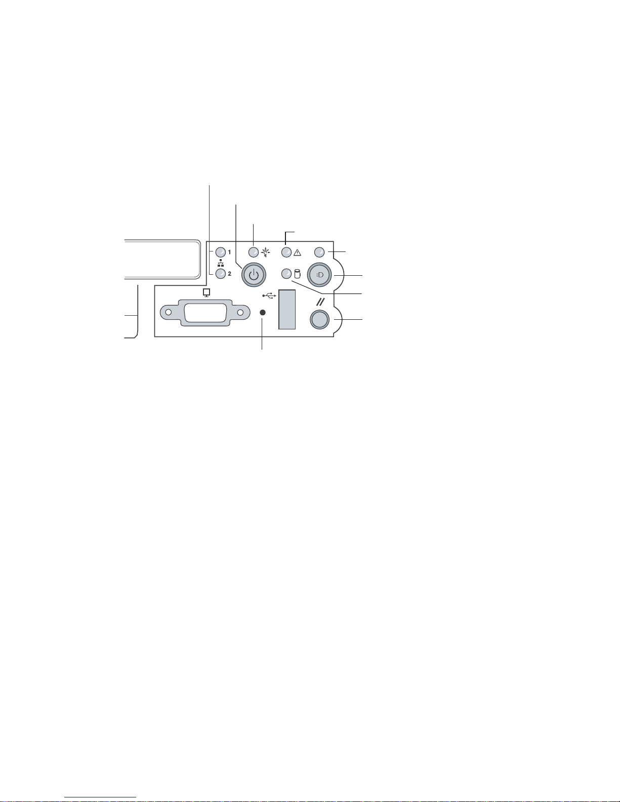
3.2.1 Front Panel LEDs and Pushbuttons
The front panel contains the pushbuttons and LEDs shown in Figure 3-1. Note that
the illustration has the bezel removed.
NIC1 and NIC2 Activity LEDs
Power/Sleep Pushbutton
Power/Sleep LED
System Status LED
NMI Pushbutton
FIGURE 3-1 Front Panel Pushbuttons and LEDs
ID LED
ID Pushbutton
Hard Disk Status LED
Reset Pushbutton
3-4 Sun Fire V60x and Sun Fire V65x Servers—Troubleshooting Guide • November 2003
Page 61

3.2.1.1 Front Panel LEDs
The front panel LEDs are summarized in Table 3-2.
TABLE 3-2 Front Panel LEDs
LED Color Function
Power Green This LED is controlled by software. It turns steady when the server is powered
up and is off when the system is off or in sleep mode.
NIC1 and NIC2 Green These LEDs are on when a good network link has been established. They blink
green to reflect network data activity.
System
Status/Fault
Hard Disk Drive
Activity
System ID Blue The blue System Identification LED is used to help identify a system for
Green/
Amber
Green The Drive Activity LED on the front panel is used to indicate drive activity from
This LED can assume different states (green, amber, steady, blinking) to indicate
critical, non-critical, or degraded server operation.
Steady green: Indicates the system is operating normally
Blinking green: Indicates the system is operating in a degraded condition.
Blinking amber: Indicates the system is in a non-critical condition.
Steady amber: Indicates the system is in a critical or non-recoverable condition.
Off: Indicates POST/system stop.
See “Front-Panel System Status LED” on page 3-9 for more details regarding
this LED.
the onboard SCSI controller. The server Main Board also provides a header,
giving access to this LED for add-in IDE or SCSI controllers.
Blinking green (random): Hard disk activity
Steady amber: Hard disk fault
Off: No disk activity nor fault condition (or power is off).
servicing when it is installed within a high density rack or cabinet that is
populated with several other similar systems. The System ID LED is illuminated
when the system ID button, located on the front panel, is pressed. If activated
by the front panel pushbutton, the LED remains on until the pushbutton is
depressed again. The LED also illuminates when the server receives a remote
System Identify command from a remote management console. In this case, the
LED turns off after a timeout period. The timeout period is configurable, with a
default of 15 seconds. An additional blue System ID LED on the Main Board is
visible through the rear panel. It mirrors the operation of the front panel LED.
Chapter 3 Troubleshooting the Server Using Built-In Tools 3-5
Page 62

3.2.1.2 Front Panel Pushbuttons
The front panel pushbuttons are summarized in Table 3-3.
TABLE 3-3 Front Panel Pushbuttons
Switch Function
Power/Sleep This pushbutton is used to toggle the system power on and off. This button is also used as a
sleep button for operating systems that follow the ACPI specification. Linux, for example,
configures the power button to the instant off mode. There is no ACPI support for the Solaris
OS.
Reset Depressing this pushbutton reboots and initializes the system.
NMI Pushing this recessed pushbutton causes a non-maskable interrupt to occur. Note that NMI
event trapping is not implemented in Linux nor Solaris.
System ID This pushbutton toggles the state of the front panel ID LED and the server Main Board ID
LED. The Main Board ID LED is visible through the rear of the chassis and allows you to
locate a particular server from behind a rack of servers.
3-6 Sun Fire V60x and Sun Fire V65x Servers—Troubleshooting Guide • November 2003
Page 63
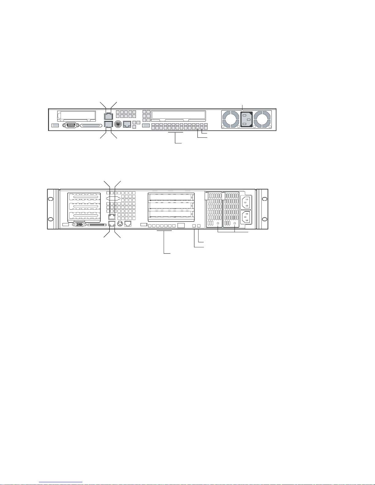
3.2.2 Rear Panel LEDs
The rear panel contains the LEDs shown in Figure 3-2.
NIC2 Network
Activity LED
NIC1 Network
Activity LED
NIC2 Network
Activity LED
NIC1 Network
Activity LED
NIC2 Network
Speed LED
NIC1 Network
Speed LED
NIC2 Network
Speed LED
NIC1 Network
Speed LED
System Status LED*
POST LEDs (4)*
*LEDs are on main board,
visible through rear of chassis
POST LEDs (4)*
*LEDs are on main board,
visible through rear of chassis
ID LED*
System Status LED*
ID LED*
Power Supply Status LED
Power Supply Status LEDs
(redundant power supplies shown)
FIGURE 3-2 Rear Panel LEDs
Chapter 3 Troubleshooting the Server Using Built-In Tools 3-7
Page 64

TABLE 3-4 Rear Panel LEDs
LED Color Function
Network Connection/
Network Activity
Green This LED is on the left side of each NIC connector.
Green = valid network connection.
Blinking = transmit or receive activity.
Network Speed Amber/Green This LED is on the right side of the NIC connector.
Off = 10 Mbps operation.
Green = 100 Mbps operation.
Amber = 1000 Mbps operation.
POST LEDs (four) Multicolor
(Red/Green/Amber)
To help diagnose power-on self test (POST) failures, a set of
four bi-color diagnostic LEDs is located on the back edge of
the server Main Board. These LEDs are visible through holes
in the rear panel. Each of the four LEDs can have one of four
states: Off, Green, Red, or Amber. For detailed information
on these LEDs, see “POST Progress Code LED Indicators” on
page 3-22.
System ID Blue This LED is located on the Main Board and is visible through
holes in the rear panel. It can provide a mechanism for
identifying one system out of a group of identical systems.
This can be particularly useful if the server is used in a rackmount chassis in a high-density, multiple-system application.
The LED is activated by depressing the front panel System ID
pushbutton or if the server receives a remote System Identify
command from a remote management console. If activated
by the front panel pushbutton, the LED remains on until the
pushbutton is depressed again. When the LED illuminates
due to a remote System Identify command, the LED turns off
after a timeout period. An additional blue System ID LED is
located on the front panel that mirrors the operation of the
rear Main Board LED.
System Status/Fault Green/Amber This LED reflects the state of the System Status LED on the
Power Supply Green/Amber This is a bi-color LED that can be on, off, green, amber, or
3-8 Sun Fire V60x and Sun Fire V65x Servers—Troubleshooting Guide • November 2003
front panel.
blinking, or combination thereof. See “Rear Panel Power
Supply Status LED” on page 3-11 for more detailed
information.
Page 65
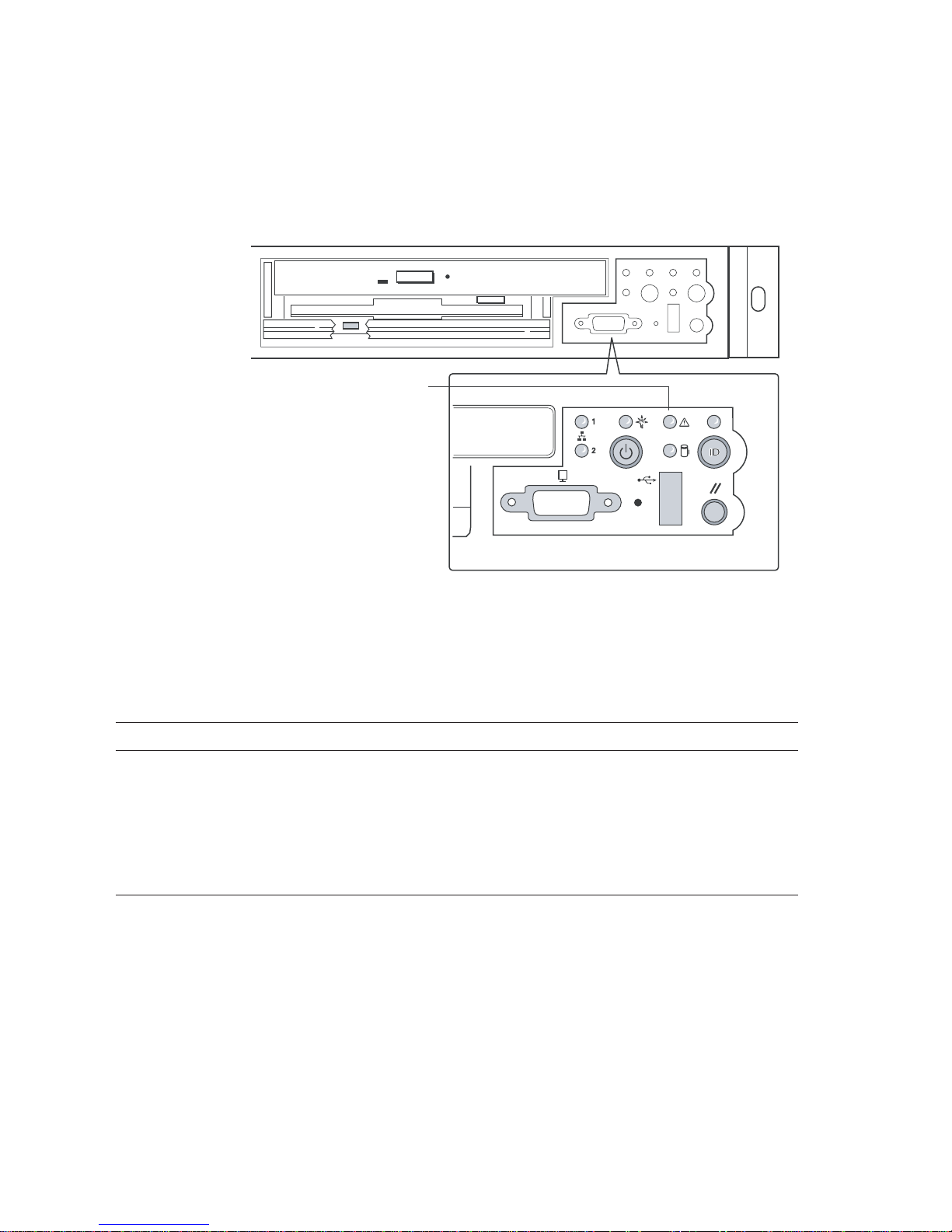
3.2.3 Front-Panel System Status LED
The front-panel system status LED is located as shown in Figure 3-3.
System Status LED
FIGURE 3-3 Location of Front-Panel System Status LED
The front-panel system status LED has the states indicated in Table 3-5.
TABLE 3-5 System Status LED States
System Status LED State System Condition
CONTINUOUS GREEN Indicates the system is operating normally.
BLINKING GREEN Indicates the system is operating in a degraded condition.
BLINKING AMBER Indicates the system is in a non-critical condition.
CONTINUOUS AMBER Indicates the system is in a critical or non-recoverable condition.
OFF Indicates POST/system stop.
Chapter 3 Troubleshooting the Server Using Built-In Tools 3-9
Page 66

Critical Condition
A critical condition or non-recoverable threshold crossing is indicated with a
continuous amber status LED and is associated with the following events:
■ Temperature, voltage, or fan critical threshold crossing.
■ Power subsystem failure. The Baseboard
1
Management Controller (BMC) asserts
this failure whenever it detects a power control fault (for example, the BMC
detects that the system power is remaining on even though the BMC has
deasserted the signal to turn off power to the system).
■ The system is unable to power up due to incorrectly installed processor(s), or
processor incompatibility.
■ A satellite controller such as the HSC, or another IMPI-capable device, such as an
add-in server management PCI card, sends a critical or non-recoverable state, via
the Set Fault Indication command to the BMC.
■ Critical Event Logging errors, including System Memory Uncorrectable ECC error
and Fatal/Uncorrectable Bus errors, such as PCI SERR and PERR.
Non-Critical Condition
A non-critical condition is indicated with a blinking amber status LED and signifies
that at least one of the following conditions is present:
■ Temperature, voltage, or fan non-critical threshold crossing.
■ Chassis intrusion.
■ Satellite controller sends a non-critical state, via the Set Fault Indication
command, to the BMC.
■ A Set Fault Indication command from the system BIOS. The BIOS may use the Set
Fault Indication command to indicate additional, non-critical status such as
system memory or CPU configuration changes.
Degraded Condition
A degraded condition is indicated with a blinking green status LED and signifies
that at least one of the following conditions is present:
■ Non-redundant power supply operation. This only applies when the BMC is
configured for a redundant power subsystem. The power unit configuration is
configured via OEM SDR records.
■ A processor is disabled by FRB or BIOS.
■ BIOS has disabled or mapped out some of the system memory.
This Troubleshooting Guide gives information on how to isolate the server
component responsible for any of the critical, non-critical, or degraded conditions
listed above.
1. Baseboard refers to the server Main Board.
3-10 Sun Fire V60x and Sun Fire V65x Servers—Troubleshooting Guide • November 2003
Page 67
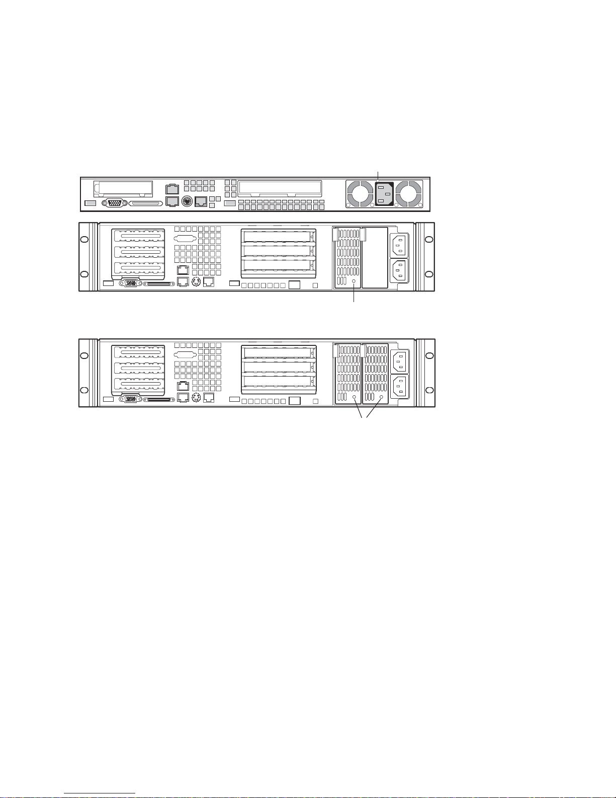
3.2.4 Rear Panel Power Supply Status LED
The rear-panel power supply status LEDs are located as shown in Figure 3-4.
Power Supply Status LED
Power Supply Status LED
(Single Power Supply)
Power Supply Status LEDs
(Redundant Power Supplies)
FIGURE 3-4 Location of Sun Fire V60x and Sun Fire V65x Servers Rear-Panel Power Supply Status LEDs
Chapter 3 Troubleshooting the Server Using Built-In Tools 3-11
Page 68

The rear-panel power supply status LED has the states indicated in Table 3-6.
TABLE 3-6 Power Supply Status LED States
Power Supply LED State Power Supply Condition
OFF No AC power present to power supply
BLINKING GREEN AC power present, but only the standby outputs are on
GREEN Power supply DC outputs are on and OK
BLINKING AMBER PSAlert# signal asserted, power supply on
AMBER Power supply shutdown due to over current, over temperature, over voltage,
or undervoltage
AMBER or OFF Power supply failed and AC fuse open or other critical failure
Note – If redundant power supplies are used in the Sun Fire V65x server, the power
supply LEDs have the following meaning:
Both LEDs off = no power to power supplies or both power supplies bad.
Both LEDs blinking green = power supplies receiving AC power, but server is off.
Both LEDs solid green = server is fully powered on and power supplies are good.
One LED solid green and one LED amber = AC power missing from one of the
power supplies.
3-12 Sun Fire V60x and Sun Fire V65x Servers—Troubleshooting Guide • November 2003
Page 69
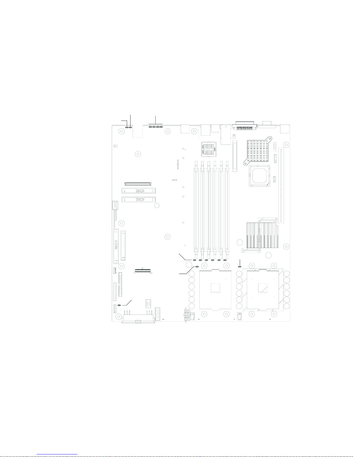
3.2.5 Server Main Board Fault LEDs
There are several fault and status LEDs built into the server board (see Figure 3-5).
Some of these LEDs are visible only when the chassis cover is removed. The LEDs
are explained in this section.
System Status
LED
ID LED
POST
LEDs
DIMM Fault
LEDs (6)
CPU 1
Fault LED
CPU 2 Fault LED
FIGURE 3-5 Fault and Status LEDs on the Server Board
5V Sytem
Standby LED
Chapter 3 Troubleshooting the Server Using Built-In Tools 3-13
Page 70

The fault LEDs are summarized below.
■ POST LEDs: To help diagnose POST failures, a set of four bi-color diagnostic
LEDs is located on the back edge of the baseboard. Each of the four LEDs can
have one of four states:
Off, Green, Red, or Amber. During the POST process, each light sequence
represents a specific Port-80 POST code. If a system should hang during POST,
the diagnostic LEDs present the last test executed before the hang. When reading
the lights, the LEDs should be observed from the back of the system. The most
significant bit (MSB) is the first LED on the left, and the least significant bit (LSB)
is the last LED on the right.
See “POST Progress Code LED Indicators” on page 3-22 for details regarding the
POST LED display.
■ CPU Fault LEDs: A fault indicator LED is located next to each of the processor
sockets. If the server Baseboard Management Controller (BMC) detects a fault in
any processor, the corresponding LED illuminates.
■ Memory Fault LEDs: A fault indicator LED is located next to each of the DIMM
sockets. If the BMC detects a fault in a given DIMM, the corresponding LED
illuminates.
One LED for each DIMM is illuminated if that DIMM has an uncorrectable or
multi-bit memory error. The LEDs maintain the same state across power switch,
power down, or loss of AC power.
■ Fan Fault LEDs: Depending on the server model, the fan header may include a
fan fault LED. If the BMC detects a fan fault, the LED illuminates. If the fan fault
LED is lit, the entire fan module must be replaced.
■ System Status LED: Indicates functional status of the server board. Glows green
when all systems are operating normally. Glows amber when one or more
systems are in a fault status. This LED mirrors the function of the system status
LED on the front panel.
See Table 3-5 on page 3-9 for a description of the LED states.
■ +5V Standby LED. This green LED is on when the server is plugged into AC
power, whether or not the server is actually powered on. AC power is applied to
the system as soon as the AC cord is plugged into the power supply.
■ System ID LED. This blue LED can be illuminated to identify the server when it
is part of a large stack of servers. See “System ID LEDs” on page 3-15 for details.
3-14 Sun Fire V60x and Sun Fire V65x Servers—Troubleshooting Guide • November 2003
Page 71
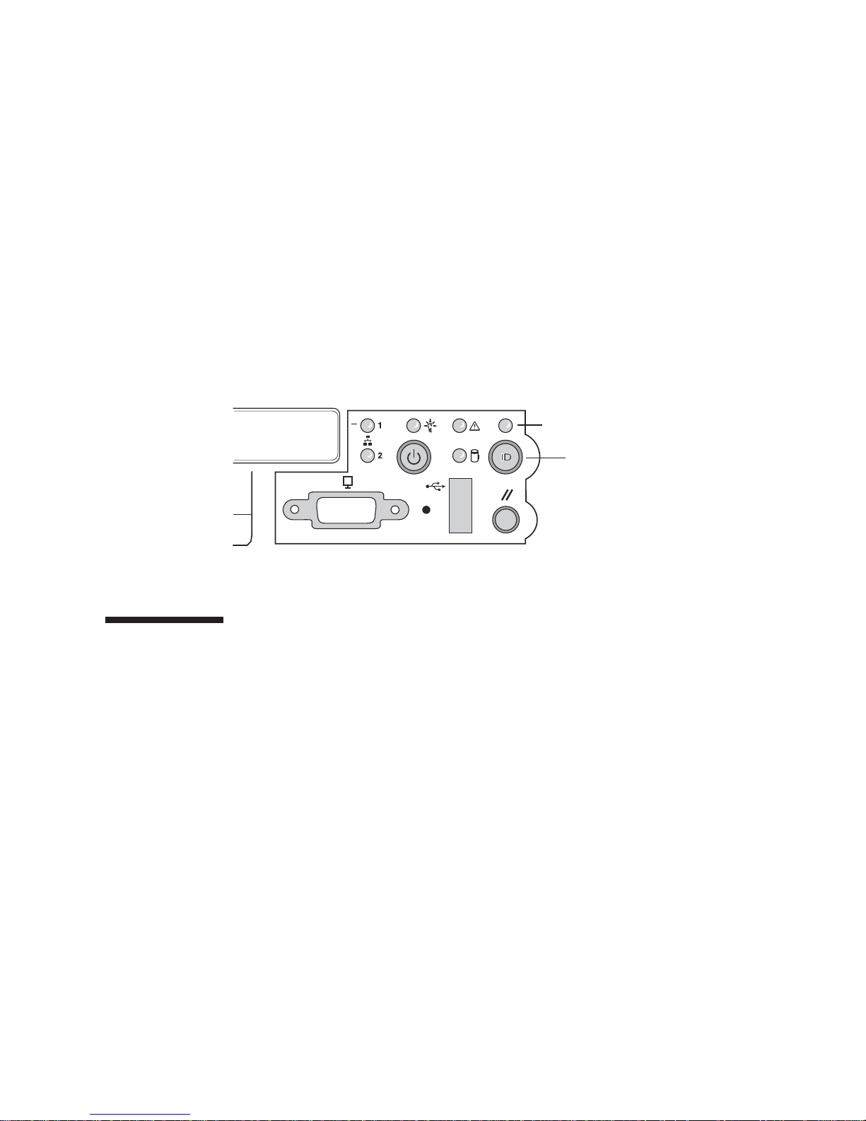
3.2.6 System ID LEDs
A pair of blue LEDs, one at the rear of the server, and one on the front panel, can be
used to easily identify the server when it is part of a large stack of servers. A single
blue LED located at the back edge of the server board next to the backup battery is
visible through the rear panel. The two LEDs mirror each other and can be
illuminated by the Baseboard Management Controller (BMC) either by pressing a
button on the chassis front panel or through server-management software. When the
button is pressed on the front panel, both LEDs illuminate and stay illuminated until
the button is pressed again. If the LED is illuminated through a remote System
Identify command, the LED turns off after a timeout period. See Figure 3-5 on
page 3-13 for the location of the rear Main Board LED. The front panel ID LED and
the ID activation button are shown in Figure 3-6.
ID LED
ID Pushbutton
FIGURE 3-6 Location of Front-Panel ID Pushbutton and LED
3.3 Power-On Self Test (POST)
The BIOS indicates the current testing phase during POST by writing a hex code to
the Enhanced Diagnostic LEDs, located on the rear of the server main board and
visible through the back of the chassis.
If errors are encountered, error messages or codes will either be displayed to the
video screen, or if an error has occurred prior to video initialization, errors will be
reported through a series of audible beep codes. POST errors are logged in to the
System Event Log (SEL).
During the power-on self test (POST), the server may indicate a system fault by:
■ Displaying error codes and messages at the display screen
■ Beeping the speaker in a coded sequence
■ Illuminating the POST LEDs, visible from the rear panel, in a coded fashion
Chapter 3 Troubleshooting the Server Using Built-In Tools 3-15
Page 72

3.3.1 POST Screen Messages
During POST, if an error is detected, the BIOS displays an error code and message to
the screen. The tables in this section describe the standard and extended POST error
codes and their associated messages. The BIOS prompts the user to press a key in
case of serious errors. Some of the error messages are preceded by the string “Error”
to highlight the fact that the system may be malfunctioning. All POST errors and
warnings are logged in the System Event Log (SEL) unless it is full. See “Managing
the System Event Log” on page 4-30 for more details on the SEL.
Note – All POST errors are logged to the SEL, which is capable of holding
approximately 3200 entries. After the SEL is full, no further errors are logged. The
SEL can be cleared using the SSU or the BIOS setup. The SEL is automatically
cleared after running the PCT. See “Managing the System Event Log” on page 4-30
for more details.
Table 3-7 and Table 3-8 contain the POST error messages and error codes.
TABLE 3-7 Standard POST Error Messages and Codes
Error Code Error Message Pause On Boot
100 Timer Channel 2 error Yes
101 Master Interrupt Controller Yes
102 Slave Interrupt Controller Yes
103 CMOS battery failure Yes
104 CMOS options not set Yes
105 CMOS checksum failure Yes
106 CMOS display error Yes
107 Insert key pressed Yes
108 Keyboard locked message Yes
109 Keyboard stuck key Yes
10A Keyboard interface error Yes
10B System memory size error Yes
10E External cache failure Yes
110 Floppy controller error Yes
111 Floppy A: error Yes
112 Floppy B: error Yes
113 Hard disk 0 error Yes
3-16 Sun Fire V60x and Sun Fire V65x Servers—Troubleshooting Guide • November 2003
Page 73

TABLE 3-7 Standard POST Error Messages and Codes (Continued)
Error Code Error Message Pause On Boot
114 Hard disk 1 error Yes
115 Hard disk 2 error Yes
116 Hard disk 3 error Yes
117 CD-ROM disk 0 error Yes
118 CD-ROM disk 1 error Yes
119 CD-ROM disk 2 error Yes
11A CD-ROM disk 3 error Yes
11B Date/time not set Yes
11E Cache memory bad Yes
120 CMOS clear Yes
121 Password clear Yes
140 PCI error Yes
141 PCI memory allocation error Yes
142 PCI IO allocation error Yes
143 PCI IRQ allocation error Yes
144 Shadow of PCI ROM failed Yes
145 PCI ROM not found Yes
146 Insufficient memory to shadow PCI ROM Yes
TABLE 3-8 Extended POST Error Messages and Codes
Error Code Error Message Pause On Boot
8100 Processor 1 failed BIST No
8101 Processor 2 failed BIST No
8110 Processor 1 internal error (IERR) No
8111 Processor 2 internal error (IERR) No
8120 Processor 1 thermal trip error No
8121 Processor 2 thermal trip error No
8130 Processor 1 disabled No
8131 Processor 2 disabled No
Chapter 3 Troubleshooting the Server Using Built-In Tools 3-17
Page 74

TABLE 3-8 Extended POST Error Messages and Codes (Continued)
Error Code Error Message Pause On Boot
8140 Processor 1 failed FRB-3 timer No
8141 Processor 2 failed FRB-3 timer No
8150 Processor 1 failed initialization on last boot. No
8151 Processor 2 failed initialization on last boot. No
8160 Processor 01: unable to apply BIOS update Yes
8161 Processor 02: unable to apply BIOS update Yes
8170 Processor P1 :L2 cache failed Yes
8171 Processor P2 :L2 cache failed Yes
8180 BIOS does not support current stepping for Processor P1 Yes
8181 BIOS does not support current stepping for Processor P2 Yes
8190 Watchdog timer failed on last boot No
8191 4:1 core to bus ratio: processor cache disabled Yes
8192 L2 Cache size mismatch Yes
8193 CPUID, processor stepping are different Yes
8194 CPUID, processor family are different Yes
8195 Front side bus speed mismatch: System halted Yes, Halt
8196 Processor models are different Yes
8197 CPU speed mismatch Yes
8198 Failed to load processor microcode Yes
8300 Baseboard Management Controller (BMC) failed to function Yes
8301 Front panel controller failed to function Yes
8305 Hotswap controller failed to function Yes
8420 Intelligent System Monitoring chassis opened Yes
84F1 Intelligent System Monitoring forced shutdown Yes
84F2 Server Management Interface failed Yes
84F3 BMC in update mode Yes
84F4 Sensor Data Record (SDR) empty Yes
84FF System event log full No
8500 Bad or missing memory in slot 3A Yes
8501 Bad or missing memory in slot 2A Yes
3-18 Sun Fire V60x and Sun Fire V65x Servers—Troubleshooting Guide • November 2003
Page 75

TABLE 3-8 Extended POST Error Messages and Codes (Continued)
Error Code Error Message Pause On Boot
8502 Bad or missing memory in slot 1A Yes
8504 Bad or missing memory in slot 3B Yes
8505 Bad or missing memory in slot 2B Yes
8506 Bad or missing memory in slot 1B Yes
8601 All memory marked as fail: forcing minimum back online Yes
3.3.2 POST Error Beep Codes
The tables in this section list the POST error beep codes. Prior to system video
initialization, the BIOS and BMC use these beep codes to notify users of error
conditions.
TABLE 3-9 BMC-Generated POST Beep Codes
Beep Code1Description
1 One short beep before boot (normal, not an error)
1-2 Search for option ROMs. One long beep and two short beeps on checksum
failure.
1-2-2-3 BIOS ROM checksum
1-3-1-1 Test DRAM refresh
1-3-1-3 Test 8742 keyboard controller
1-3-3-1 Auto size DRAM. System BIOS stops execution here if the BIOS does not
detect any usable memory DIMMs.
1-3-4-1 Base RAM failure. BIOS stops execution here if entire memory is bad.
2-1-2-3 Check ROM copyright notice.
2-2-3-1 Test for unexpected interrupts.
1-5-1-1 FRB failure (processor failure)
1-5-2-2 No processors installed or processor socket 1 is empty
1-5-2-3 Processor configuration error (for example, mismatched VIDs)
1-5-2-4 Front-side bus select configuration error (for example, mismatched BSELs)
Chapter 3 Troubleshooting the Server Using Built-In Tools 3-19
Page 76

TABLE 3-9 BMC-Generated POST Beep Codes
Beep Code1Description
1-5-4-2 Power fault: DC power unexpectedly lost (for example, power good from the
power supply was deasserted)
1-5-4-3 Chipset control failure
1-5-4-4 Power control failure (for example, power good from the power supply did
not respond to power request)
1 The code indicates the beep sequence; for example, 1-5-1-1 means a single beep, then a
pause, then 5 beeps in a row, then a pause, then a single beep, then a pause, and then
finally a single beep.
TABLE 3-10
Beep
Code Error Message Description
BIOS-Generated Boot Block POST Beep Codes
1 Refresh timer failure The memory refresh circuitry on the motherboard is faulty.
2 Parity error Parity can not be reset
3 Base memory failure Base memory test failure. See Table 3-11 on page 3-21 for
additional error details.
4 System timer System timer is not operational
5 Processor failure Processor failure detected
6 Keyboard controller Gate A20
failure
The keyboard controller may be bad. The BIOS cannot switch
to protected mode.
7 Processor exception interrupt error The CPU generated an exception interrupt.
8 Display memory read/write error The system video adapter is either missing or its memory is
faulty. This is not a fatal error.
9 ROM checksum error System BIOS ROM checksum error
10 Shutdown register error Shutdown CMOS register read/write error detected
11 Invalid BIOS General BIOS ROM error
3-20 Sun Fire V60x and Sun Fire V65x Servers—Troubleshooting Guide • November 2003
Page 77

TABLE 3-11 Memory 3-Beep and LED POST Error Codes
Debug Port
80h Error
Beep Code
3 00h Off Off Off Off No memory was found in the system
3 01h Off Off Off G Memory mixed type detected
3 02h Off Off G Off EDO is not supported
3 03h Off Off G G First row memory test failure
3 04h Off G Off Off Mismatched DIMMs in a row
3 05h Off G Off G Base memory test failure
3 06h Off G G Off Failure on decompressing post
3 07h Off G G G Generic memory error
Indicator
MSB LSB
Diagnostic LED Decoder
(G = green, R = red, A = amber) Meaning
module
08h
09h G Off Off G
0Ah
0Bh G Off G G
0Ch
0Dh G G Off G
3 0Eh G G G Off SMBUS protocol error
3 0Fh G G G G Generic memory error
GOffOffOff
GOffGOff
GGOffOff
3.3.2.1 BIOS Recovery Beep Codes
In rare cases, when the system BIOS has been corrupted, a BIOS recovery process
must be followed to restore system operability. During recovery mode, the video
controller is not initialized. One high-pitched beep announces the start of the
recovery process. The entire process takes two to four minutes. A successful update
ends with two high-pitched beeps. In the event of a failure, two short beeps are
generated and a flash code sequence of 0E9h, 0EAh, 0EBh, 0ECh, and 0EFh appears
at the Port 80 diagnostic LEDs (see Table 3-12 on page 3-22).
Chapter 3 Troubleshooting the Server Using Built-In Tools 3-21
Page 78

TABLE 3-12 BIOS Recovery Beep Codes
Error
Beep Code
Message Port 80h LED Indicators Description
1 Recovery
2 Recovery
Series of long lowpitched single beeps
Two long high
pitched beeps
started
boot error
Recovery
failed
Recovery
complete
Flashing series of post
codes:
E9h
EAh
EBh
ECh
EFh
EEh Unable to process valid BIOS recovery
EFh BIOS recovery succeeded, ready for
Start recovery process.
Unable to boot to floppy, ATAPI, or
ATAPI CDROM. Recovery process will
retry.
images. BIOS already passed control to OS
and flash utility.
powerdown, reboot.
3.3.3 POST Progress Code LED Indicators
To help diagnose POST failures, a set of four bi-color diagnostic LEDs is located on
the back edge of the server main board. Each of the four LEDs can have one of four
states: Off, Green, Red, or Amber.
The LED diagnostics feature consists of a hardware decoder and four dual color
LEDs. During boot block POST and post boot block POST, the LEDs display all
normal Port 80 codes representing the progress of the BIOS POST. Each POST code is
represented by a combination of colors from the four LEDs. The LEDs are in pairs of
green and red. The POST codes are broken into two nibbles, an upper and a lower
nibble. Each bit in the upper nibble is represented by a red LED and each bit in the
lower nibble is represented by a green LED. If both bits are set in the upper and
lower nibble then both red and green LEDs are lit, resulting in an amber color.
Likewise, if both bits are clear, the red and green LEDs are off.
3-22 Sun Fire V60x and Sun Fire V65x Servers—Troubleshooting Guide • November 2003
Page 79
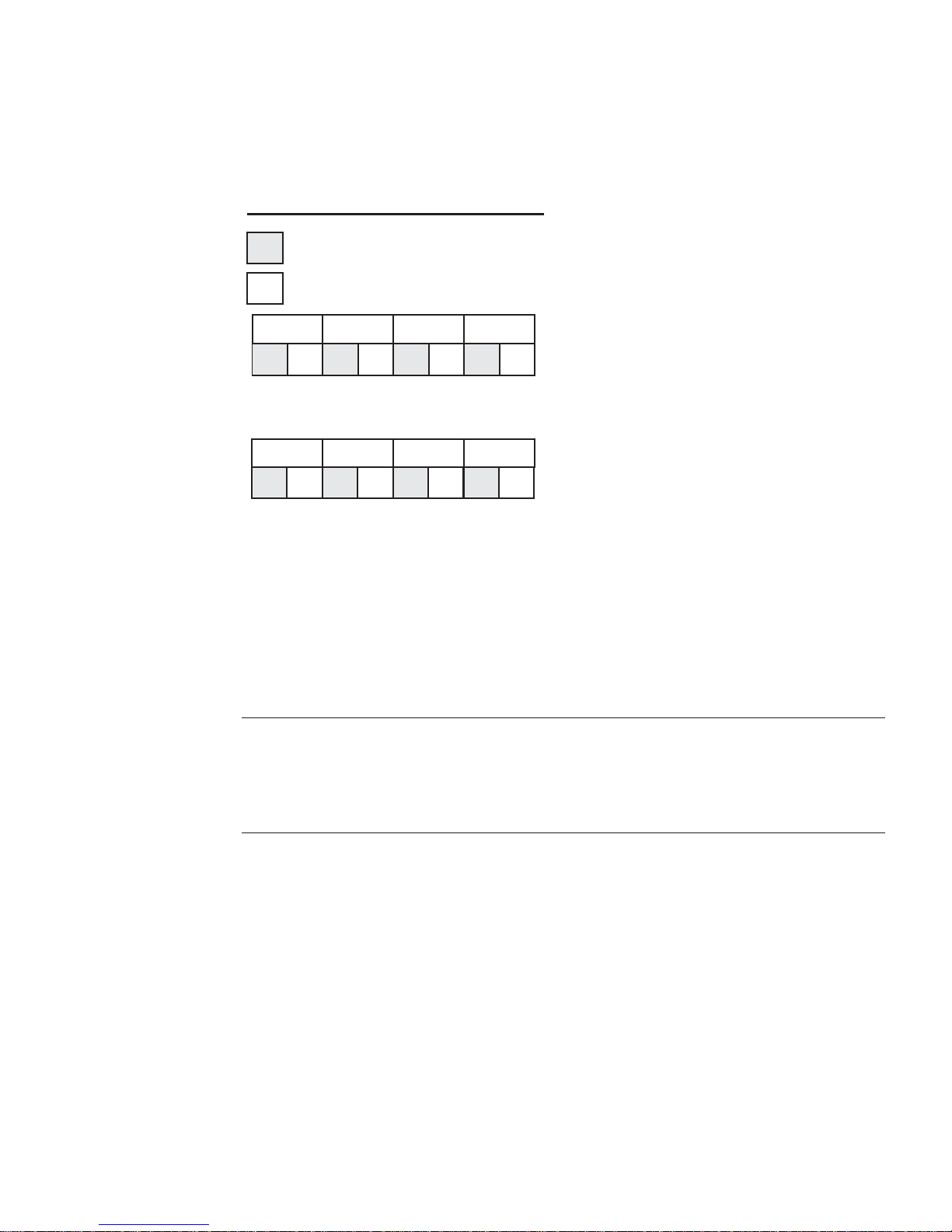
Figure 3-7 shows examples of how the POST LEDs are coded.
POST LEDs (as viewed from back of server)
= upper nibble bits
= lower nibble bits
RED
1 0 0 1 0 0 1 1
high bits
(on left)
AMBER
1 1 1 0 0 1 0 0
high bits
(on left)
FIGURE 3-7 Examples of POST LED Coding
GREEN OFF
RED GREEN
AMBER
low bits
(on right)
OFF
low bits
(on right)
POST Code = 95h
upper nibble = 1001 = 9h
lower nibble = 0101 = 5h
POST Code = CAh
upper nibble = 1100 = Ch
lower nibble = 1010 = Ah
During the POST process, each light sequence represents a specific Port-80 POST
code. If a system should hang during POST, the diagnostic LEDs present the last test
executed before the hang. When you read the LEDs, observe them from the back of
the system. The most significant bit (MSB) is the leftmost LED, and the least
significant bit (LSB) is the rightmost LED.
Note – When comparing a diagnostic LED color sequence from the server Main
Board to those listed in the diagnostic LED decoder in the following tables, the LEDs
on the Main Board should be referenced when viewed by looking into the system
from the back. Reading the LEDs from left to right, the most-significant bit is located
on the left.
Chapter 3 Troubleshooting the Server Using Built-In Tools 3-23
Page 80

TABLE 3-13 Boot Block POST Progress LED Code Table (Port 80h Codes)
POST
Code
Diagnostic LED Decoder
(G = green, R = red, A = amber) Description
MSB LSB
MSB LSB
10h Off Off Off R The NMI is disabled. Start power-on delay. Initialization code
checksum verified.
11h Off Off Off A Initialize the DMA controller, perform the keyboard controller BAT
test, start memory refresh, and enter 4 GB flat mode.
12h Off Off G R Get start of initialization code and check BIOS header.
13h Off Off G A Memory sizing.
14h Off G Off R Test base 512K of memory. Return to real mode. Execute any OEM
patches and set up the stack.
15h Off G Off A Pass control to the uncompressed code in shadow RAM. The
initialization code is copied to segment 0 and control will be
transferred to segment 0.
16h Off G G R Control is in segment 0. Verify the system BIOS checksum. If the
system BIOS checksum is bad, go to checkpoint code E0h; otherwise,
going to checkpoint code D7h.
17h Off G G A Pass control to the interface module.
18h G Off Off R Decompression of the main system BIOS failed.
19h G Off Off A Build the BIOS stack. Disable USB controller. Disable cache.
1Ah G Off G R Uncompress the POST code module. Pass control to the POST code
module.
1Bh A R Off R Decompress the main system BIOS runtime code.
1Ch A R Off A Pass control to the main system BIOS in shadow RAM.
E0h R R R Off Start of recovery BIOS. Initialize interrupt vectors, system timer, DMA
controller, and interrupt controller.
E8h A R R Off Initialize extra module if present.
E9h A R R G Initialize floppy controller.
EAh A R A Off Try to boot floppy diskette.
EBh A R A G If floppy boot fails, initialize ATAPI hardware.
ECh A A R Off Try booting from ATAPI CD-ROM drive.
EEh A A A Off Jump to boot sector.
3-24 Sun Fire V60x and Sun Fire V65x Servers—Troubleshooting Guide • November 2003
Page 81

TABLE 3-14 POST Progress LED Code Table (Port 80h Codes)
POST
Code
Diagnostic LED Decoder
(G = green, R = red, A = amber) Description
MSB LSB
20h Off Off R Off Uncompress various BIOS modules.
22h Off Off A Off Verify password checksum.
24h Off G R Off Verify CMOS checksum.
26h Off G A Off Read microcode updates from BIOS ROM.
28h G Off R Off Initializing the processors. Set up processor registers. Select least
featured processor as the BSP.
2Ah G Off A Off Go to Big Real mode.
2Ch G G R Off Decompress INT13 module.
2Eh G G A Off Keyboard controller test: the keyboard controller input buffer is
free. Next, the BAT command will be issued to the keyboard
controller.
30h Off Off R R Swap keyboard and mouse ports, if needed.
32h Off Off A R Write command byte 8042: the initialization after the keyboard
controller BAT command test is done. The keyboard command
byte will be written next.
34h Off G R R Keyboard Init: the keyboard controller command byte is written.
Next, the pin 23 and 24 blocking and unblocking commands will
be issued.
36h Off G A R Disable and initialize the 8259 programmable interrupt controller.
38h G Off R R Detect configuration mode, such as CMOS clear.
3Ah G Off A R Chipset initialization before CMOS initialization.
3Ch G G R R Init system timer: the 8254 timer test is over. Starting the legacy
memory refresh test next.
3Eh G G A R Check refresh toggle: the memory refresh line is toggling.
Checking the 15 second on/off time next.
40h Off R Off Off Calculate CPU speed.
42h Off R G Off Init interrupt vectors: interrupt vector initialization is done.
44h Off A Off Off Enable USB controller in chipset.
46h Off A G Off Initialize SMM handler. Initialize USB emulation.
48h G R Off Off Validate NVRAM areas. Restore from backup if corrupted.
Chapter 3 Troubleshooting the Server Using Built-In Tools 3-25
Page 82

TABLE 3-14 POST Progress LED Code Table (Port 80h Codes) (Continued)
POST
Code
Diagnostic LED Decoder
(G = green, R = red, A = amber) Description
4Ah G R G Off Load defaults in CMOS RAM if bad checksum or CMOS clear
jumper is detected.
4Ch G A Off Off Validate date and time in RTC.
4Eh G A G Off Determine number of microcode patches present.
50h Off R Off R Load microcode to all CPUs.
52h Off R G R Scan SMBIOS GPNV areas.
54h Off A Off R Early extended memory tests.
56h Off A G R Disable DMA.
58h G R Off R Disable video controller.
5Ah G R G R 8254 timer test on channel 2.
5Ch G A Off R Enable 8042. Enable timer and keyboard IRQs. Set video mode
initialization before setting the video mode is complete.
Configuring the monochrome mode and color mode settings next.
5Eh G A G R Initialize PCI devices and motherboard devices. Pass control to
video BIOS. Start serial console redirection.
60h Off R R Off Initialize memory test parameters.
62h Off R A Off Initialize AMI display manager module. Initialize support code
for headless system if no video controller is detected.
64h Off A R Off Start USB controllers in chipset.
66h Off A A Off Set up video parameters in BIOS data area.
68h G R R Off Activate ADM: the display mode is set. Displaying the power-on
message next.
6Ah G R A Off Initialize language module. Display splash logo.
6Ch G A R Off Display sign on message, BIOS ID, and processor information.
6Eh G A A Off Detect USB devices.
70h Off R R R Reset IDE Controllers.
72h Off R A R Displaying bus initialization error messages.
74h Off A R R Display setup message: the new cursor position has been read and
saved. Displaying the hit setup message next.
76h Off A A R Ensure timer keyboard interrupts are on.
78h G R R R Extended background memory test start.
7Ah G R A R Disable parity and NMI reporting.
3-26 Sun Fire V60x and Sun Fire V65x Servers—Troubleshooting Guide • November 2003
Page 83

TABLE 3-14 POST Progress LED Code Table (Port 80h Codes) (Continued)
POST
Code
Diagnostic LED Decoder
(G = green, R = red, A = amber) Description
7Ch G A R R Test 8237 DMA controller: the DMA page register test passed.
Performing the DMA controller 1 base register test next.
7Eh G A A R Initialize 8237 DMA controller: the DMA controller 2 base register
test passed. Programming DMA controllers 1 and 2 next.
80h R Off Off Off Enable mouse and keyboard: the keyboard test has started.
Clearing the output buffer and checking for stuck keys. Issuing
the keyboard reset command next
82h R Off G Off Keyboard interface test: A keyboard reset error or stuck key was
found. Issuing the keyboard controller interface test command
next.
84h R G Off Off Check stuck key enable keyboard: the keyboard controller
interface test is complete. Writing the command byte and
initializing the circular buffer next.
86h R G G Off Disable parity NMI: the command byte was written and global
data initialization has completed. Checking for a locked key next.
88h A Off Off Off Display USB devices.
8Ah A Off G Off Verify RAM size: Checking for a memory size mismatch with
CMOS RAM data next.
8Ch A G Off Off Lock out PS/2 keyboard/mouse if unattended start is enabled.
8Eh A G G Off Initialize boot devices: the adapter ROM had control and has now
returned control to the BIOS POST. Performing any required
processing after the option ROM returned control.
90h R Off Off R Display IDE mass storage devices.
92h R Off G R Display USB mass storage devices.
94h R G Off R Report the first set of POST errors to Error Manager.
96h R G G R Boot password check: the password was checked. Performing any
required programming before Setup next.
98h A Off Off R Float processor initialize: performing any required initialization
before the coprocessor test next.
9Ah A Off G R Enable Interrupts 0, 1, 2: checking the extended keyboard,
keyboard ID, and NUM Lock key next. Issuing the keyboard ID
command next.
9Ch A G Off R Initialize FDD devices. Report second set of POST errors to error
messager.
9Eh A G G R Extended background memory test end.
Chapter 3 Troubleshooting the Server Using Built-In Tools 3-27
Page 84

TABLE 3-14 POST Progress LED Code Table (Port 80h Codes) (Continued)
POST
Code
Diagnostic LED Decoder
(G = green, R = red, A = amber) Description
A0h R Off R Off Prepare and run setup: Error manager displays and logs POST
errors. Waits for user input for certain errors. Execute setup.
A2h R Off A Off Set base expansion memory size.
A4h R G R Off Program chipset setup options, build ACPI Tables, and build
INT15h E820h table.
A6h R G A Off Set display mode.
A8h A Off R Off Build SMBIOS table and MP tables.
AAh A Off A Off Clear video screen.
ACh A G R Off Prepare USB controllers for operating system.
AEh A G A Off One beep to indicate end of POST. No beep if silent boot is
enabled.
000h Off Off Off Off POST completed. Passing control to INT 19h boot loader next.
3-28 Sun Fire V60x and Sun Fire V65x Servers—Troubleshooting Guide • November 2003
Page 85

3.4 Contacting Technical Support
For technical support, call the phone numbers listed below, according to your
location.
United States1-800-USA-4SUN (1-800-872-4786)
UK Tel: +44 870-600-3222
France Tel: +33 1 34 03 5080
Germany Tel: +49 1805 20 2241
Italy Tel: +39 02 92595228, Toll Free 800 605228
Spain Tel: +011 3491 767 6000
See the following link for US, Europe, South America, Africa, and APAC local
country telephone numbers:
http://www.sun.com/service/contacting/solution.html
For general support and documentation on the servers, see the following link:
http://www.sun.com/supporttraining/
Chapter 3 Troubleshooting the Server Using Built-In Tools 3-29
Page 86

3-30 Sun Fire V60x and Sun Fire V65x Servers—Troubleshooting Guide • November 2003
Page 87

CHAPTER
4
Powering On and Configuring the
Server
This chapter explains how to use the Power On switch to apply power to the server,
boot to the operating system, use the serial console, update system software, and
validate the operation of the Sun Fire V60x and Sun Fire V65x servers. The chapter
contains these sections:
“Jumper Locations” on page 4-2
■
■
“Setting the Serial COM2 Port Jumper” on page 4-4
“Powering On” on page 4-5
■
“Clearing CMOS” on page 4-6
■
■
“Booting Up” on page 4-8
“Loading the Operating System” on page 4-16
■
“Hyper-threading
■
■
“Configuring an External Serial Console” on page 4-17
“Fault Resilient Booting (FRB)” on page 4-19
■
“Using the Service Partition Menu” on page 4-24
■
■
“Using the Sun Diagnostics CD” on page 4-45
“Updating the Server Configuration” on page 4-50
■
“Restarting and Shutting Down” on page 4-55
■
TM
CPU Feature” on page 4-16
4-1
Page 88
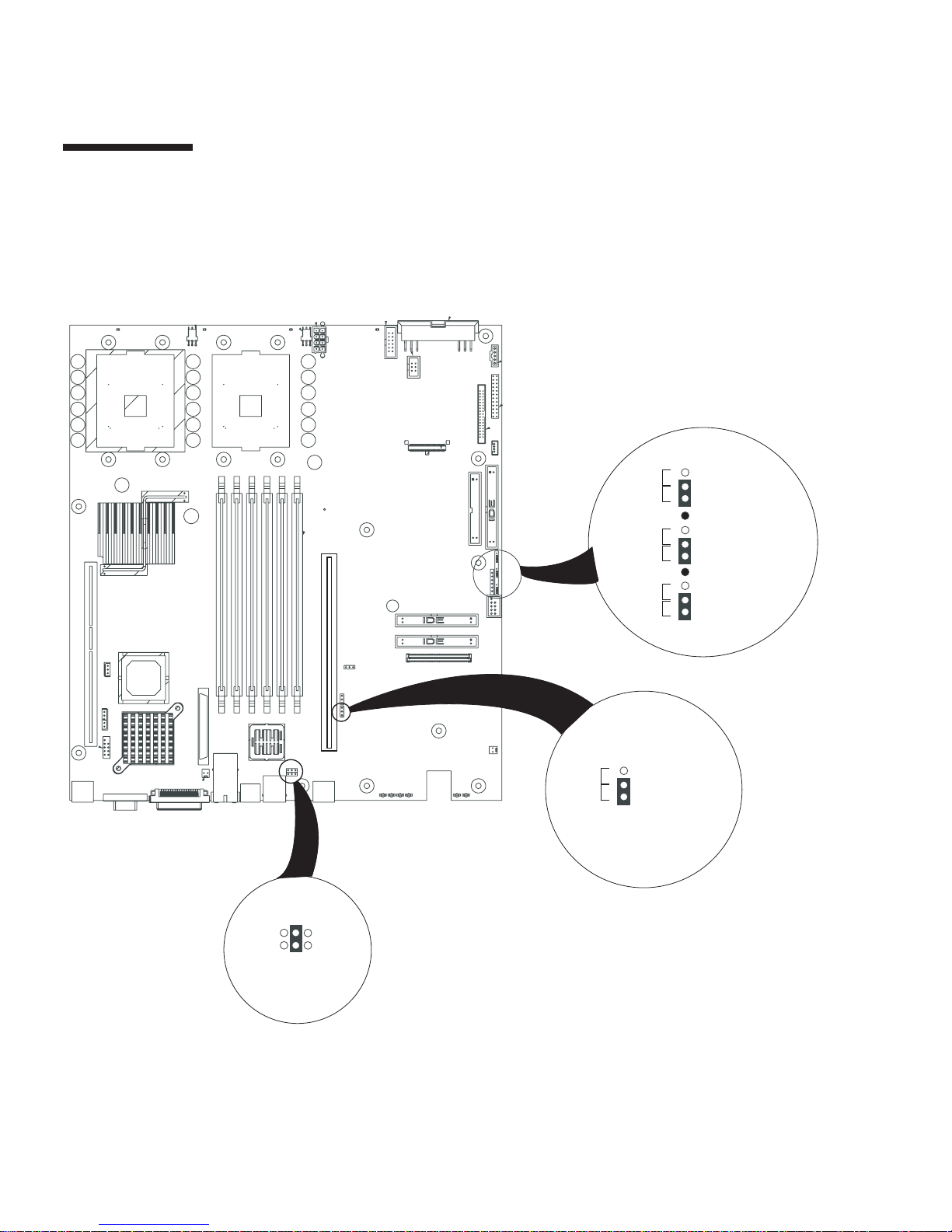
4.1 Jumper Locations
Part of configuring the server involves setting the jumper positions on the main
board. The jumper locations are shown in Figure 4-1 and summarized in Table 4-1.
NN
Recover
Normal
Clear
Normal
Clear
Normal
I
1
2
3
2
4
6
1
3
5
3-4 = DSR
1-2 = DCD
Write En
J5A2
1
2
RCVR\BOOT
3
4
5
6
CLR\PSWD
7
8
9
CLR\CMOS
10
11
BMC BB WENormal
FIGURE 4-1
4-2
Main Board Jumper Locations
Sun Fire V60x and Sun Fire V65x Servers—Troubleshooting Guide • November 2003
Page 89

TABLE 4-1
Designator Jumper Name Action at System Reset
Jumper Function Summary
J5A2 RJ-45 Serial COM2 Port
Configuration
Configures either a DSR or a DCD signal to the connector. See
“Rear Panel RJ-45 Serial COM2 Connector” in Chapter 2 of the
Sun Fire V60x and Sun Fire V65x Server User Guide
and “Setting
the Serial COM2 Port Jumper” on page 4-4 of this document.
CLR\CMOS Clear CMOS If these pins are jumpered, the CMOS settings are cleared. These
pins should not be jumpered for normal operation.
CLR\PSWD Clear Password If these pins are jumpered, the password is cleared. These pins
should not be jumpered for normal operation.
RCVR\BOOT BIOS Boot Recovery If these pins are jumpered, the system will attempt BIOS
recovery. These pins should not be jumpered for normal
operation.
BMC BB WE BMC Boot Block Write
Enable
If these pins are jumpered, BMC boot block is erasable and
programmable at next reset. These pins should not be jumpered
for normal operation.
Chapter 4 Powering On and Configuring the Server
4-3
Page 90
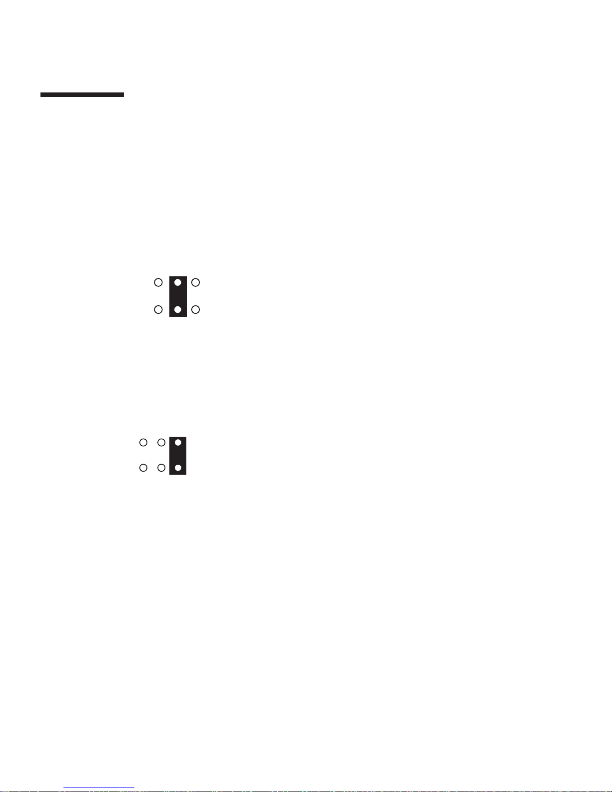
4.2 Setting the Serial COM2 Port Jumper
A serial port jumper on the Main Board is preset by default to the position that
satisfies most serial port configurations. The jumper is located at the rear of the
server, on the Main Board, next to the rear RJ-45 serial connector. The jumper is on
the jumper block labeled J5A2. The top cover of the server must be removed to
access the jumper.
For serial devices that require a DSR signal (default), the J5A2 jumper block must be
configured as follows: place the jumper across positions 3 and 4 (the two middle
jumper posts) as shown in Figure 4-2.
1
3
5
2
4
6
J5A2 Jumper Block
(viewed from front of server)
FIGURE 4-2
J5A2 Jumper Block Configured for DSR Signal (pin 7 connected to DSR)
For serial devices that require a DCD signal, the J5A2 jumper block must be
configured as follows: place the jumper across positions 1 and 2 as shown in
Figure 4-3.
1
3
5
2
4
6
J5A2 Jumper Block
(viewed from front of server)
FIGURE 4-3
J5A2 Jumper Block Configured for DCD Signal (pin 7 connected to DCD)
4-4
Sun Fire V60x and Sun Fire V65x Servers—Troubleshooting Guide • November 2003
Page 91
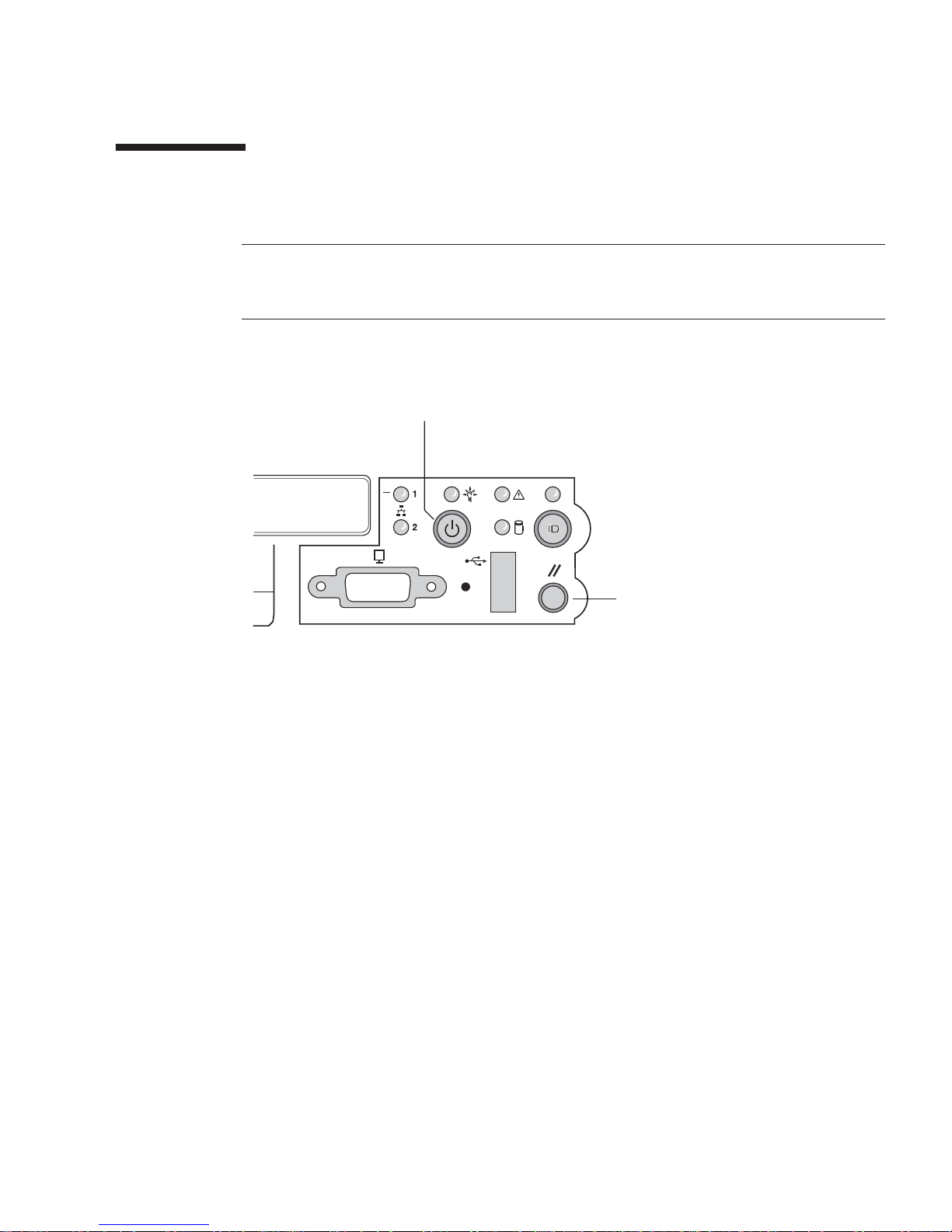
4.3 Powering On
Caution –
does not isolate the equipment from the AC power being supplied through the AC
power cord.
The location of the switch is shown in Figure 4-4.
FIGURE 4-4
Pushing the power pushbutton sends a signal to monitoring circuitry inside the
server. The switch does not directly control high-voltage AC; it controls only lowvoltage signals. When the monitoring circuitry detects that the button has been
depressed, it activates the power supply and powers up the server. Likewise, when
the server is powered up, pushing the switch powers the server down.
The power switch on the front of the server is an On/Off switch, but it
Power/Sleep Pushbutton
Reset Pushbutton
Power and Reset Switches on the Front Panel
The main method for isolating the server from all high voltage is to physically
remove the AC power cord. If the power cord is not removed, the only other way to
isolate the server from high voltage is to open all external circuit breakers that
supply AC voltage to the equipment.
Chapter 4 Powering On and Configuring the Server
4-5
Page 92

Caution –
Advanced Configuration and Power (ACPI) enabled. As a result, the front panel
power switch operates as a normal power switch. In this configuration, press the
switch once and power comes on; press again and the power goes off. It is
recommended that you use the standard shutdown command before you power
down the system using the switch. Activate the front panel switch to remove power
only when the OS (for example, Linux) has completed the shutdown process and has
halted.
Should you elect to use an ACPI-enabled Linux kernel and run the ACPI daemon
(acpid), the behavior of the front panel switch will change to support the standard
“soft-off” capability. That is, when the server is on and the power switch is pressed,
the OS is notified and begins a graceful shutdown.
Additionally, with ACPI enabled and the server on, pressing the power button for
longer than four seconds forces an immediate (non-graceful) shutdown.
Note that the Solaris OS does not support ACPI.
As shipped, the Sun Fire V60x and Sun Fire V65x servers do not have
4.4 Clearing CMOS
It may be necessary to clear CMOS memory in order to restore the default BIOS
passwords required to boot the server (user) or access setup functions (supervisor),
as well as the default BIOS settings.
The CMOS configuration RAM may be reset by one of two methods:
The CMOS clear button sequence from the front panel.
■
■
The Clear CMOS jumper located on the baseboard
The CMOS can also be set to a default setting through the BIOS Setup. It will
automatically be reset if it becomes corrupted.
4.4.1 Using the Front Panel
Follow these steps to clear the CMOS using the buttons on the front panel:
1. Power off the system, but leave the AC power connected so the 5V standby is
available.
2. Verify that the Clear CMOS jumper is in the “not clear” position.
4-6
Sun Fire V60x and Sun Fire V65x Servers—Troubleshooting Guide • November 2003
Page 93

3. Hold down the reset button for at least 4 seconds.
4. While the reset button is still depressed, press the power on/off button and hold
for at least 2 seconds.
5. Simultaneously release both the power on/off and reset buttons.
Upon completion of these steps, the BMC asserts the clear CMOS signal to emulate
the movement of the Clear CMOS jumper. The BIOS clears CMOS as if you had
moved the Clear CMOS jumper on the main board. CMOS is cleared only once per
front panel button sequence. The BMC releases the CMOS clear line during the next
system reset. Removing the Clear CMOS jumper from the main board can disable
the Front Panel CMOS reset function. In addition, the jumper should be retained in
case the CMOS needs to be cleared using the baseboard header.
4.4.2 Using the Clear CMOS Jumper
Follow these steps to clear the CMOS using the CLR\CMOS jumper on the main
board (see Figure 4-5):
1. Power off the system, but leave the AC power connected so the 5V standby is
available.
2. Verify that the CLR\CMOS jumper is in the “Clear” position.
3. Press the power on/off button.
When the BIOS detects a reset CMOS request (either through the front panel or with
the Clear CMOS jumper), CMOS defaults are loaded during the next POST sequence.
Note that non-volatile storage for embedded devices may or may not be affected by
the clear CMOS operation depending on the available hardware support.
4. Place the CLR\CMOS jumper in the “Normal” position.
Chapter 4 Powering On and Configuring the Server
4-7
Page 94
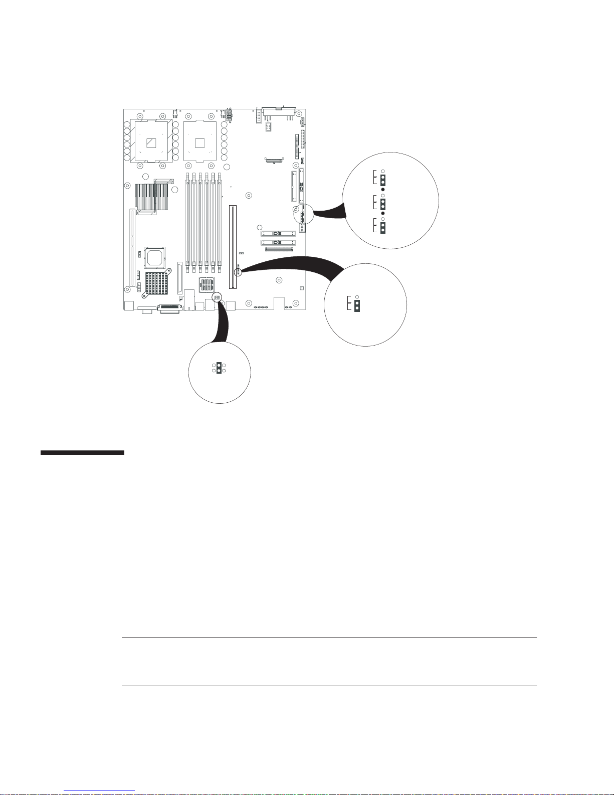
Clear
Clear
10
11
1
2
3
4
5
6
7
8
9
RCVR\BOOT
CLR\PSWD
CLR\CMOS
Recover
Normal
Normal
Normal
NN
I
6
4
2
J5A2
5
3
1
3-4 = DSR
1-2 = DCD
FIGURE 4-5
Location of Clear CMOS Jumper
4.5 Booting Up
As soon as power is applied to the server, the bootup process begins. Boot messages
are sent to either a monitor attached to the video port, or to a serial console attached
to the rear RJ-45 serial COM2 port.
The server is configured by default to initially send BIOS and kernel messages to
both the serial port and the video port. However, when the boot process reaches the
OS load point, the messages and screens are sent only to the video port. After
bootup is finished, the configuration can be changed to send all messages to the
serial console (see “Configuring an External Serial Console” on page 4-17).
Write En
1
2
BMC BB WENormal
3
Note –
The USB ports may be disabled until the OS is booted and the USB drivers
are installed. A PS/2 keyboard is required if a keyboard is necessary for initial
bootup and configuration.
4-8
Sun Fire V60x and Sun Fire V65x Servers—Troubleshooting Guide • November 2003
Page 95
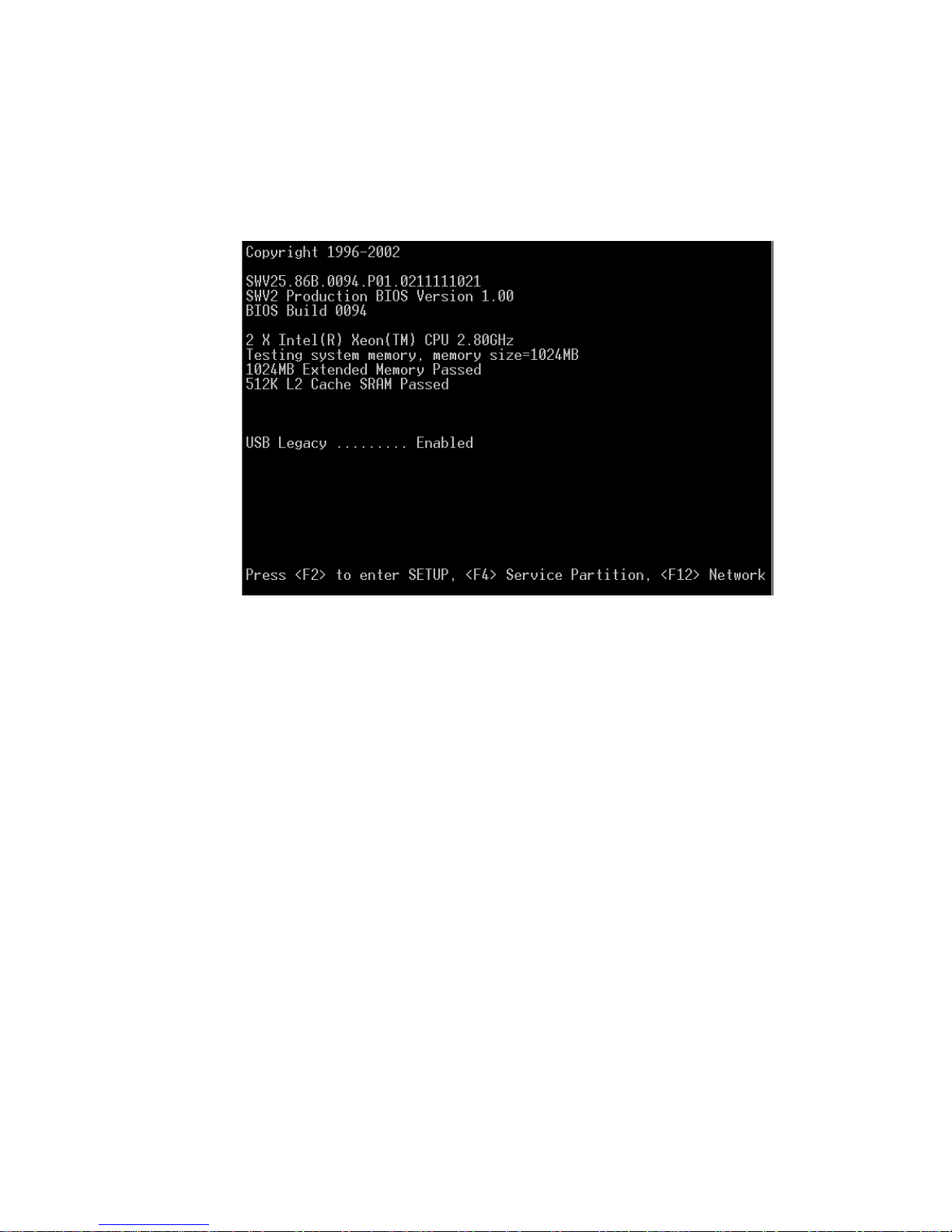
4.5.1 Boot Options
The first bootup screen is shown in Figure 4-6.
FIGURE 4-6
First BIOS Bootup Screen
At the bottom of the screen, you are given the option to press the following function
keys:
■
F2 to enter the BIOS Setup Utility
If the service partition is installed, F4 for the Service Partition (a DOS partition
■
allowing setup configuration and server testing)
■
F12 to boot from the Network
4.5.1.1 BIOS Setup Utility <F2>
Press F2 to enter the BIOS Setup Utility. The main BIOS Setup Utility screen shown
in Figure 4-7 appears.
Chapter 4 Powering On and Configuring the Server
4-9
Page 96
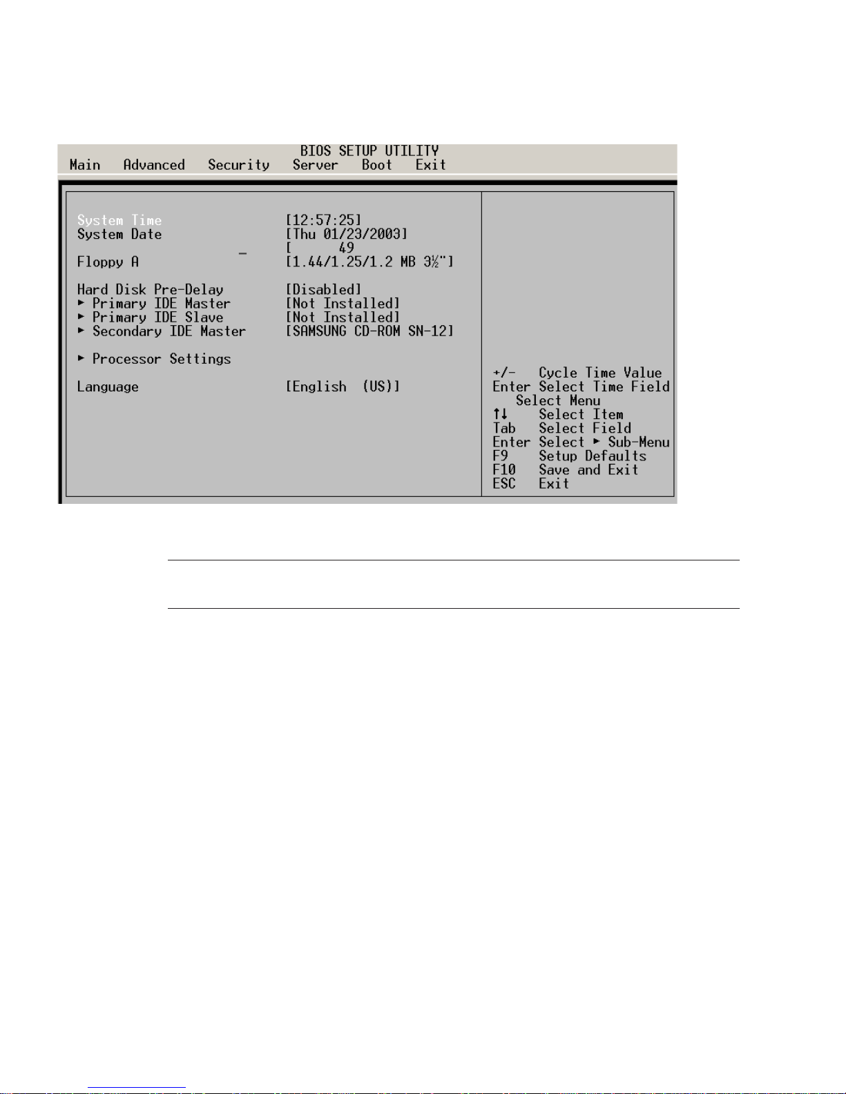
FIGURE 4-7
BIOS Setup Utility Main Screen
Caution –
Changing the BIOS settings may cause undesirable effects, and in some
cases may disable the server. Be very careful before changing the BIOS configuration.
It is important to note the default boot sequence. The boot sequence is accessed by
using the right arrow key to select the Boot menu item on the top of the BIOS screen,
then pressing Enter. The boot sequence is then displayed. The default boot sequence
is as shown in Figure 4-8.
4-10
Sun Fire V60x and Sun Fire V65x Servers—Troubleshooting Guide • November 2003
Page 97
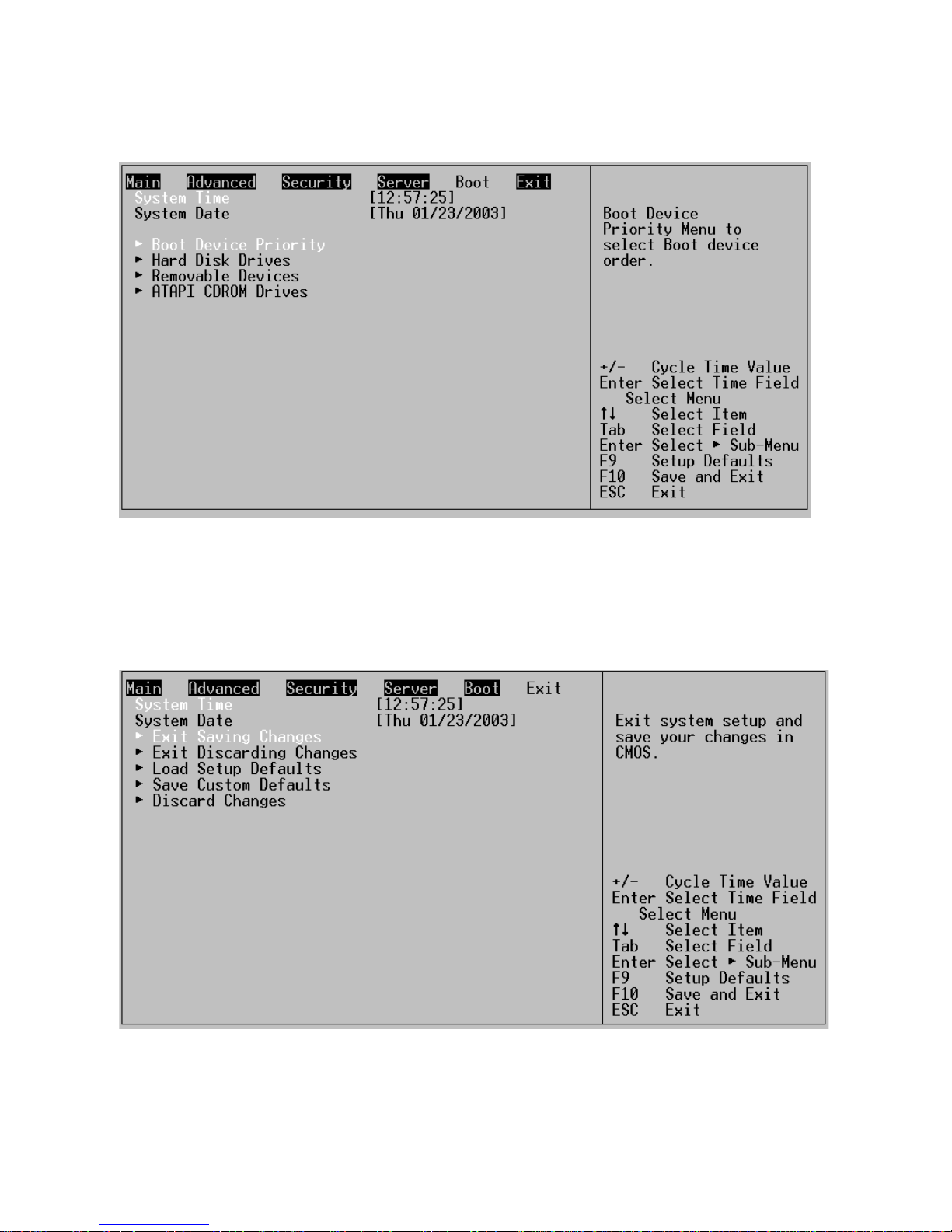
FIGURE 4-8
Default Boot Sequence
You can always restore all of the default BIOS settings by scrolling to the Exit menu
item along the top of the screen. The BIOS Setup screen then appears as shown in
Figure 4-9.
FIGURE 4-9
BIOS Setup Utility Exit Screen
Chapter 4 Powering On and Configuring the Server
4-11
Page 98

To restore all of the default settings, scroll to “Load Setup Defaults” and press Enter,
then select Yes at the prompt and press Enter again. Now press F10 to save the
settings and exit.
When you exit the BIOS setup utility, the bootup process continues.
Note –
To update the server BIOS, see “Updating the Server Configuration” on
page 4-50.
4.5.1.2 Service Partition <F4>
Note –
operating environment preinstalled, the Service Partition is also preinstalled. If your
server does not have a preinstalled operating system, the Service Partition is not
installed. The Service Partition can be installed as described in “Service Partition” on
page 4-47.
The Service Partition is a special partition that contains utilities used to manage and
configure the Server. If the Service Partition is installed, use one of the following
methods to access the menu:
■
■
The Service Partition Menu will display (see Figure 4-32).
If you have a Sun Fire V60x server or Sun Fire V65x server with the Solaris
Linux operating environment
Solaris operating environment
Subsystem menu and select the DIAGNOSTIC partition.
: Press <F4> during bootup..
: Let the system boot up to the Solaris Primary Boot
4-12
If the Service Partition is not installed, you can install it, or you can also run the
utilities directly from the Sun Diagnostics CD. Refer to “Service Partition” on
page 4-47 for information on installing or restoring the Service Partition, or running
the utilities from the Sun Diagnostics CD.
Note –
The operations performed with the service partition menus can also be
executed from the Sun Fire V60x and Sun Fire V65x servers Diagnostic CD. See
“Using the Sun Diagnostics CD” on page 4-45.
When you are finished using the service partition, you must depress the Ctrl-AltDelete keys simultaneously to reboot.
Sun Fire V60x and Sun Fire V65x Servers—Troubleshooting Guide • November 2003
Page 99
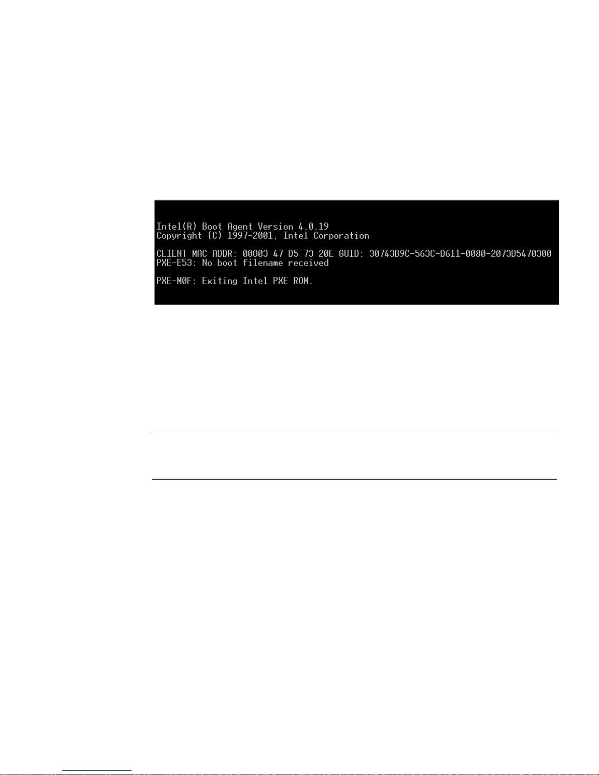
4.5.1.3 Network Boot <F12>
If you press F12 to boot from the network, the server software looks for a valid boot
file name on the network. If it finds such a file name, it boots from the network. If it
cannot find a valid file name, it gives up and continues to boot from the hard disk.
Figure 4-10 is an example of how the screen appears when booting from the network
fails.
FIGURE 4-10
Network Boot Failed Screen
Pre-boot Execution Environment (PXE) is a method by which the server can be
booted from a remote server. This allows the system to boot without any knowledge
of the Operating System on the server. The PXE environment uses DHCP to obtain
network addresses. PXE is primarily used for loading operating systems, configuring
the system, or burn-in type testing. PXE booting will only work if a properly
configured PXE server is available.
Note –
If you use the F12 key to initiate a boot from the network, you will not have
the opportunity to choose the Ethernet port from which to boot. If you want to have
a choice of which port to boot from, use the Esc key to initiate the network boot.
4.5.1.4 Choose Boot Device <ESC>
Press the Esc key to go to the boot device selection menu. This menu, shown in
Figure 4-11, allows you to select the device from which the system will boot. To
select a boot device, scroll to the desired device and press Enter; otherwise, press Esc
to exit without changing the boot device.
Chapter 4 Powering On and Configuring the Server
4-13
Page 100
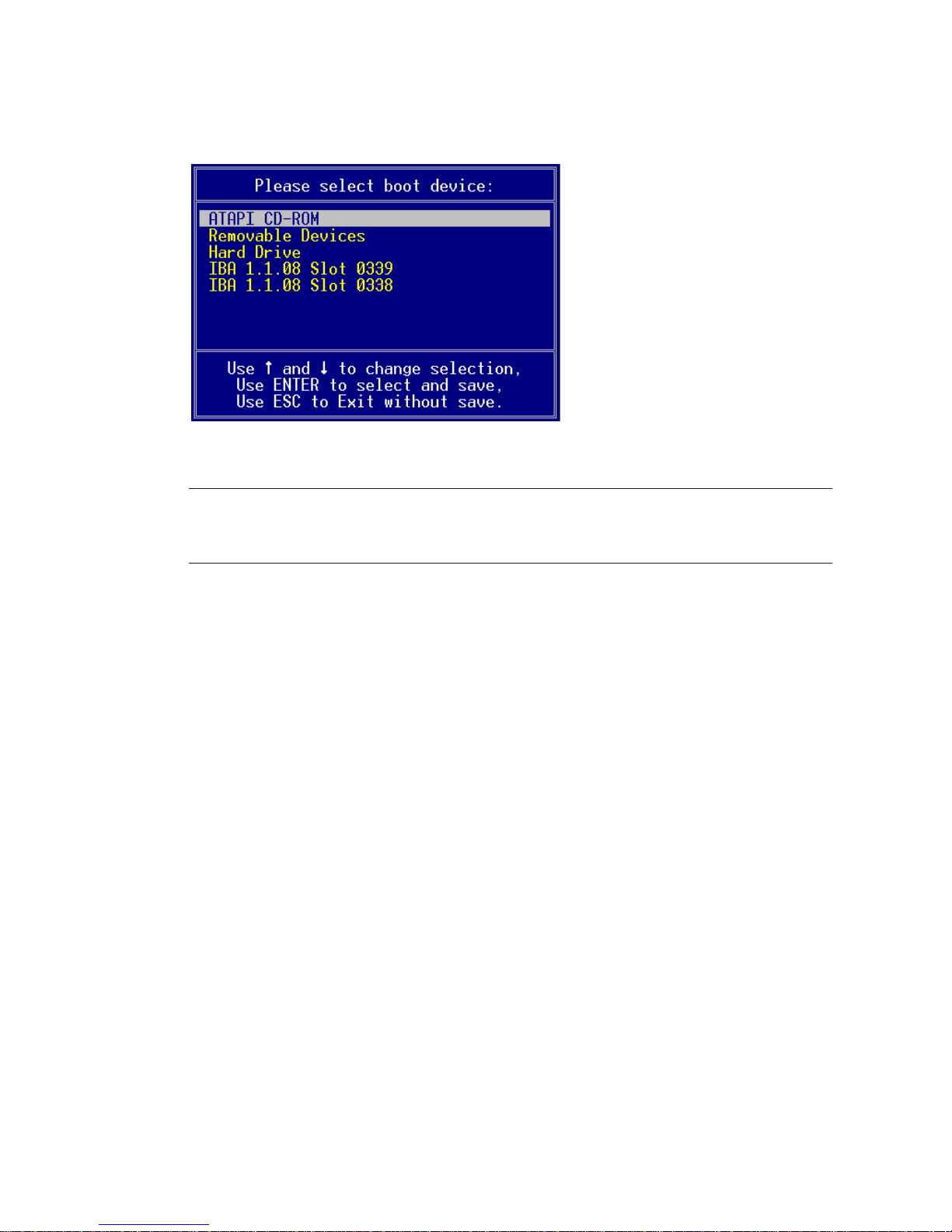
.
FIGURE 4-11
Note –
affects the current boot. Subsequent boots revert to the device stored in the BIOS
default settings.
Boot Device Selection Menu
When you select a boot device with the menu shown in Figure 4-11, it only
4.5.2 Other Bootup Items
During the boot process, you will be presented with the choices described in the
following sections. Type “N” to keep the current information, “Y” to change the
information.
4.5.2.1 Ethernet Port Delay
Ethernet ports may take a short amount of time (less than 1second) to activate after
ifconfig brings them up. This has been noted when the Server is running Red Hat
Linux v7.2 or v7.3.
4.5.2.2 USB-Connected External CD-ROM Drives
Some USB-connected CD-ROM devices perform unreliably on the Sun Fire V60x
server and Sun Fire V65x server. Use the internal CD-ROM device when possible.
4-14
Sun Fire V60x and Sun Fire V65x Servers—Troubleshooting Guide • November 2003
 Loading...