

Page 1

Sun Fire™V480 Server
Administration Guide
Sun Microsystems, Inc.
901 San Antonio Road
Palo Alto, CA 94303-4900 U.S.A.
650-960-1300
Part No. 816-0904-10
February 2002 Revision A
Send comments about this document to: [email protected]
Page 2

Copyright 2002Sun Microsystems,Inc., 901 SanAntonio Road, Palo Alto, California94303, U.S.A. All rights reserved.
Sun Microsystems, Inc.has intellectual property rights relating totechnology embodied in theproduct thatis described inthis
document. Inparticular,and without limitation,these intellectual property rights may includeone or more of theU.S. patents
listed athttp://www.sun.com/patentsand one or more additionalpatents or pending patentapplications in the U.S. andin other
countries.
This documentand the product to whichit pertains are distributed under licensesrestricting theiruse, copying, distribution,and
decompilation. Nopart of the product orof this document may bereproduced inany form by any meanswithout prior written
authorization ofSun and its licensors, ifany.
Third-party software, including fonttechnology, iscopyrighted and licensed from Sunsuppliers.
Parts ofthe productmay be derivedfrom BerkeleyBSD systems, licensed from theUniversity of California. UNIXis a registered
trademark inthe U.S. and in othercountries, exclusively licensed through X/OpenCompany,Ltd.
Sun, Sun Microsystems, theSun logo, Sun Fire, Solaris,VIS, Sun StorEdge, SolsticeDiskSuite, Java, SunVTS and theSolaris logo are
trademarks orregistered trademarksof Sun Microsystems, Inc. inthe U.S. and other countries.
All SPARCtrademarks areused underlicense and are trademarks or registeredtrademarks of SPARC International, Inc.in theU.S. and
other countries.Products bearingSPARCtrademarks are based uponan architecturedeveloped by Sun Microsystems, Inc.
The OPENLOOK and Sun™ Graphical UserInterface was developed bySun Microsystems,Inc. for itsusers andlicensees. Sun
acknowledges thepioneering effortsof Xerox in researching and developing theconcept of visual orgraphical user interfaces for the
computer industry. Sunholds anon-exclusive license from Xeroxto the Xerox Graphical User Interface,which licensealso covers Sun’s
licensees whoimplement OPEN LOOK GUIs andotherwise comply with Sun’swritten license agreements.
Federal Acquisitions:Commercial Software—Government Users Subject to StandardLicense Terms and Conditions.
DOCUMENTATION IS PROVIDED "AS IS" AND ALL EXPRESS OR IMPLIED CONDITIONS, REPRESENTATIONS AND
WARRANTIES, INCLUDINGANY IMPLIED WARRANTY OF MERCHANTABILITY,FITNESS FOR APARTICULAR PURPOSEOR
NON-INFRINGEMENT,ARE DISCLAIMED, EXCEPT TOTHE EXTENT THAT SUCH DISCLAIMERSARE HELD TO BELEGALLY
INVALID.
Copyright 2002Sun Microsystems,Inc., 901 SanAntonio Road, Palo Alto, California94303, Etats-Unis. Tous droits réservés.
Sun Microsystems, Inc. a les droits de propriété intellectuels relatants à la technologie incorporée dans le produit qui est décrit dans
ce document.En particulier, et sansla limitation, ces droits de propriété intellectuelspeuvent inclureun ou plus desbrevets américains
énumérés à http://www.sun.com/patents et un ou les brevets plus supplémentaires ou les applications de brevet en attente dans les
Etats-Unis et dans les autres pays.
Ce produit ou document est protégé par un copyright et distribué avec des licences qui en restreignent l’utilisation, la copie, la
distribution, et la décompilation. Aucune partie de ce produit ou document ne peut être reproduite sous aucune forme, parquelque
moyen que ce soit, sans l’autorisation préalable et écrite de Sun et de ses bailleurs de licence, s’il y ena.
Le logiciel détenu par des tiers, et qui comprend la technologie relative aux polices de caractères, est protégé par un copyright et
licencié par des fournisseurs de Sun.
Des parties de ce produit pourront être dérivées des systèmes Berkeley BSD licenciés par l’Université de Californie. UNIX est une
marque déposée aux Etats-Unis et dans d’autres pays et licenciée exclusivement par X/Open Company, Ltd.
Sun, Sun Microsystems, le logo Sun, Sun Fire, Solaris, VIS, Sun StorEdge, Solstice DiskSuite, Java, SunVTS et le logo Solaris sont des
marques de fabrique ou des marques déposées de Sun Microsystems, Inc. aux Etats-Unis et dans d’autres pays.
Toutes les marques SPARC sont utilisées sous licence et sont des marques de fabrique ou des marques déposées de SPARC
International, Inc. aux Etats-Unis et dans d’autres pays. Les produits protant les marques SPARC sont basés sur une architecture
développée par Sun Microsystems, Inc.
L’interface d’utilisationgraphique OPENLOOK et Sun™ a été développéepar SunMicrosystems, Inc.pour sesutilisateurs et licenciés.
Sun reconnaît les efforts de pionniers de Xerox pour la recherche et le développment du concept des interfaces d’utilisation visuelle
ou graphique pour l’industrie de l’informatique. Sundétient une license non exclusive do Xerox surl’interface d’utilisation graphique
Xerox, cette licence couvrant également les licenciées de Sun qui mettent en place l’interface d ’utilisation graphique OPEN LOOK et
qui en outre se conforment aux licences écrites de Sun.
LA DOCUMENTATION EST FOURNIE "EN L’ÉTAT" ET TOUTES AUTRES CONDITIONS, DECLARATIONS ET GARANTIES
EXPRESSES OU TACITES SONT FORMELLEMENT EXCLUES, DANS LA MESURE AUTORISEE PAR LA LOI APPLICABLE, Y
COMPRIS NOTAMMENT TOUTE GARANTIE IMPLICITE RELATIVE A LA QUALITE MARCHANDE, A L’APTITUDE A UNE
UTILISATION PARTICULIERE OU A L’ABSENCE DE CONTREFAÇON.
Please
Recycle
Page 3

Declaration of Conformity
Compliance Model Number: Cherrystone
Product Family Name: Sun Fire V480
EMC
European Union
This equipment complies with the following requirements of the EMC Directive 89/336/EEC:
EN55022:1998/CISPR22:1997 Class A
EN550024:1998 Required Limits (as applicable):
EN61000-4-2 4 kV (Direct), 8 kV (Air)
EN61000-4-3 3 V/m
EN61000-4-4 1.0 kV Power Lines, 0.5 kV Signal and DC Power Lines
EN61000-4-5 1 kV AC Line-Line and Outdoor Signal Lines
2 kV AC Line-Gnd, 0.5 kV DC Power Lines
EN61000-4-6 3 V
EN61000-4-8 1 A/m
EN61000-4-11 Pass
EN61000-3-2:1995 + A1, A2, A14 Pass
EN61000-3-3:1995 Pass
Safety
This equipment complies with the following requirements of the Low Voltage Directive 73/23/EEC:
EC Type Examination Certificates:
EN60950:1992, 2nd Edition, Amendments 1, 2, 3, 4, 11 TÜV Rheinland Licence No. S 2171515
IEC 950:1991, 2nd Edition, Amendments 1, 2, 3, 4 CB Scheme Certificate No. Pending Due 12/14/01
Evaluated to all CB Countries UL Listing: E113363; Vol. 15, 16; Sec. 3, 5
Supplementary Information
This product was tested and complies with all the requirements for the CE Mark.
Burt Hemp 11 Dec. 2001
Manager, Compliance Engineering
Sun Microsystems, Inc.
One Network Drive
Burlington, MA 01803
USA
Tel: 781-442-0006
Fax: 781-442-1673
Peter Arkless 11 Dec. 2001
Quality Manager
Sun Microsystems Scotland, Limited
Springfield, Linlithgow
West Lothian, EH49 7LR
Scotland, United Kingdom
Tel: 0506-670000
Fax: 1506-672323
iii
Page 4

iv Sun Fire V480 Server Parts Installation and Removal Guide • February 2002
Page 5

Regulatory Compliance Statements
Your Sun product is marked to indicate its compliance class:
• Federal Communications Commission (FCC) — USA
• Industry Canada Equipment Standard for Digital Equipment (ICES-003) — Canada
• Voluntary Control Council for Interference (VCCI) — Japan
• Bureau of Standards Metrology and Inspection (BSMI) — Taiwan
Please read the appropriate section that corresponds to the marking on your Sun product before attempting to install the
product.
FCC ClassA Notice
This device complies with Part 15 of the FCC Rules. Operation is subject to the following two conditions:
1. This device may not cause harmful interference.
2. This device must accept any interference received, including interference that may cause undesired operation.
Note: This equipment has been tested and found to comply with the limits for a Class A digital device, pursuant to Part 15 of
the FCC Rules. These limits are designed to provide reasonable protection against harmful interference when the equipment
is operated in a commercial environment. This equipment generates, uses, and can radiate radio frequency energy, and if it is
not installed and used in accordance with the instruction manual, it maycause harmful interference to radio communications.
Operation of this equipment in a residential area is likely to cause harmful interference, in which case the user will be required
to correct the interference at his own expense.
Shielded Cables:Connections between the workstationand peripherals must bemade using shieldedcables to comply with
FCC radio frequency emission limits. Networking connections can be made using unshielded twisted-pair (UTP) cables.
Modifications: Any modifications made to this device that are not approved by Sun Microsystems, Inc. may void the
authority granted to the user by the FCC to operate this equipment.
FCC ClassB Notice
This device complies with Part 15 of the FCC Rules. Operation is subject to the following two conditions:
1. This device may not cause harmful interference.
2. This device must accept any interference received, including interference that may cause undesired operation.
Note: This equipment has been tested and found to comply with the limits for a Class B digital device, pursuant to Part 15 of
the FCC Rules. These limits are designed to provide reasonable protection against harmful interference in a residential
installation. This equipment generates, uses and can radiate radio frequency energy and, if not installed and used in
accordance with the instructions, may cause harmful interference to radio communications. However, there is no guarantee
that interference will not occur in a particular installation. If this equipment does cause harmful interference to radio or
television reception,which can be determined by turning the equipment offand on, the user is encouraged to try to correct the
interference by one or more of the following measures:
• Reorient or relocate the receiving antenna.
• Increase the separation between the equipment and receiver.
• Connect the equipment into an outlet on a circuit different from that to which the receiver is connected.
• Consult the dealer or an experienced radio/television technician for help.
Shielded Cables: Connections between the workstation and peripherals must be made using shielded cables in order to
maintain compliance with FCC radio frequency emission limits. Networking connections can be made using unshielded
twisted pair (UTP) cables.
Modifications: Any modifications made to this device that are not approved by Sun Microsystems, Inc. may void the
authority granted to the user by the FCC to operate this equipment.
v
Page 6
ICES-003 ClassA Notice - Avis NMB-003, Classe A
This Class A digital apparatus complies with Canadian ICES-003.
Cet appareil numérique de la classe A est conforme à la norme NMB-003 du Canada.
ICES-003 Class BNotice - Avis NMB-003,Classe B
This Class B digital apparatus complies with Canadian ICES-003.
Cet appareil numérique de la classe B est conforme à la norme NMB-003 du Canada.
vi Sun Fire V480 Server Administration Guide • February 2002
Page 7
BSMI Class ANotice
The following statement is applicable to products shipped to Taiwan and marked as Class A on the product compliance
label.
Regulatory Compliance Statements vii
Page 8

viii Sun Fire V480 Server Administration Guide • February 2002
Page 9

Contents
Preface xxv
Part One – Installation 1
1. Sun Fire V480 Server Installation 3
About the Parts Shipped to You 4
How to Install the Sun Fire V480 Server 5
Part Two – Background 9
2. System Overview 11
About the Sun Fire V480 Server 12
Locating Front Panel Features 15
Security Lock and Top Panel Lock 15
LED Status Indicators 16
Power Button 18
System Control Switch 18
Locating Back Panel Features 20
About Reliability, Availability, and Serviceability Features 22
Hot-Pluggable and Hot-Swappable Components 22
1+1 Power Supply Redundancy 23
Environmental Monitoring and Control 23
ix
Page 10

Automatic System Recovery 24
MPxIO 25
Sun Remote System Control 25
Hardware Watchdog Mechanism and XIR 26
Dual-Loop Enabled FC-AL Subsystem 26
Support for RAID Storage Configurations 27
Error Correction and Parity Checking 27
3. Hardware Configuration 29
About Hot-Pluggable and Hot-Swappable Components 30
Power Supplies 30
Disk Drives 31
About the CPU/Memory Boards 31
About the Memory Modules 32
Memory Interleaving 34
Independent Memory Subsystems 34
Configuration Rules 35
About the PCI Cards and Buses 35
Configuration Rules 37
About the Sun Remote System Control Card 38
Configuration Rules 40
About Hardware Jumpers 40
PCI Riser Board Jumpers 41
RSC Card Jumpers 42
About the Power Supplies 43
Configuration Rule 45
About the Fan Trays 45
Configuration Rule 46
About FC-AL Technology 47
x Sun Fire V480 Server Administration Guide • February 2002
Page 11

About the FC-AL Backplane 48
Configuration Rules 49
About the HSSDC FC-AL Port 49
About the FC-AL Host Adapters 50
Configuration Rules 50
About the Internal Disk Drives 50
Configuration Rule 51
About the Serial Port 51
About the USB Ports 52
4. Network Interfaces and System Firmware 53
About the Network Interfaces 54
About Redundant Network Interfaces 55
About the ok Prompt 55
What You Should Know About Accessing the ok Prompt 56
Ways of Reaching the ok Prompt 57
Graceful Halt 57
L1-A or Break Key Sequence 57
Externally Initiated Reset (XIR) 57
Manual System Reset 58
For More Information 58
About OpenBoot Environmental Monitoring 58
Enabling or Disabling the OpenBoot Environmental Monitor 59
Automatic System Shutdown 59
OpenBoot Environmental Status Information 60
About OpenBoot Emergency Procedures 60
OpenBoot Emergency Procedures for Systems With Non-USB
Keyboards 61
OpenBoot Emergency Procedures for Systems With USB Keyboards 61
Contents xi
Page 12

Stop-A Functionality 61
Stop-N Functionality 61
Stop-F Functionality 62
Stop-D Functionality 63
About Automatic System Recovery 63
Auto-Boot Options 64
Error Handling Summary 64
Reset Scenarios 65
ASR User Commands 66
5. System Administration Software 67
About System Administration Software 68
About Multipathing Software 69
For More Information 69
About Volume Management Software 70
VERITAS Dynamic Multipathing 70
Multiplexed I/O (MPxIO) 71
RAID Concepts 71
Disk Concatenation 72
RAID 1: Disk Mirroring 72
RAID 0: Disk Striping 73
RAID 5: Disk Striping With Parity 73
Hot Spares (Hot Relocation) 73
For More Information 74
About Sun Cluster Software 74
For More Information 74
About Communicating With the System 75
What the System Console Does 75
Using the System Console 76
xii Sun Fire V480 Server Administration Guide • February 2002
Page 13

Default System Console Configuration 76
Alternative System Console Configuration 76
6. Diagnostic Tools 79
About the Diagnostic Tools 80
About Diagnostics and the Boot Process 84
Stage One: OpenBoot Firmware and POST 84
What Are POST Diagnostics For? 85
What POST Diagnostics Do 86
What POST Error Messages Tell You 87
Controlling POST Diagnostics 88
Stage Two: OpenBoot Diagnostics Tests 90
What Are OpenBoot Diagnostics Tests For? 91
Controlling OpenBoot Diagnostics Tests 91
What OpenBoot Diagnostics Error Messages Tell You 95
I2C Bus Device Tests 95
Other OpenBoot Commands 96
Stage Three: The Operating Environment 99
Error and System Message Log Files 99
Solaris System Information Commands 99
Tools and the Boot Process: A Summary 106
About Isolating Faults in the System 106
About Monitoring the System 108
Monitoring the System Using Sun Remote System Control 108
Monitoring the System Using Sun Management Center 109
How Sun Management Center Works 110
Other Sun Management Center Features 111
Who Should Use Sun Management Center? 111
Obtaining the Latest Information 112
Contents xiii
Page 14

About Exercising the System 112
Exercising the System Using SunVTS Software 113
SunVTS Software and Security 114
Exercising the System Using Hardware Diagnostic Suite 114
When to Run Hardware Diagnostic Suite 115
Requirements for Using Hardware Diagnostic Suite 115
Reference for OpenBoot Diagnostics Test Descriptions 116
Reference for Decoding I2C Diagnostic Test Messages 118
Reference for Terms in Diagnostic Output 121
Part Three – Instructions 123
7. Configuring Devices 125
How to Avoid Electrostatic Discharge 126
How to Power On the System 128
How to Power Off the System 130
How to Get to the ok Prompt 132
How to Attach a Twisted-Pair Ethernet Cable 133
How to Access the System Console via tip Connection 134
How to Modify the /etc/remote File 136
How to Verify Serial Port Settings 138
How to Set Up an Alphanumeric Terminal as the System Console 139
How to Configure a Local Graphics Terminal as the System Console 141
How to Initiate a Reconfiguration Boot 144
Reference for System Console OpenBoot Variable Settings 147
8. Configuring Network Interfaces and the Boot Device 149
How to Configure the Primary Network Interface 150
How to Configure Additional Network Interfaces 152
How to Select the Boot Device 155
xiv Sun Fire V480 Server Administration Guide • February 2002
Page 15

9. Configuring System Firmware 159
How to Enable OpenBoot Environmental Monitoring 160
How to Disable OpenBoot Environmental Monitoring 160
How to Obtain OpenBoot Environmental Status Information 161
How to Enable the Watchdog Mechanism and Its Options 162
How to Enable ASR 163
How to Disable ASR 164
How to Obtain ASR Status Information 164
How to Redirect the System Console to RSC 165
How to Restore the Local System Console 166
To Restore the Local Console to Your ttya Port 167
To Restore the Local Console to Your Graphics Console 167
How to Unconfigure a Device Manually 168
How to Reconfigure a Device Manually 170
10. Isolating Failed Parts 173
How to Operate the Locator LED 174
How to Put the Server in Diagnostic Mode 175
How to Isolate Faults Using LEDs 176
How to Isolate Faults Using POST Diagnostics 179
How to Isolate Faults Using Interactive OpenBoot Diagnostics Tests 180
How to View Diagnostic Test Results After the Fact 183
How to View and Set OpenBoot Configuration Variables 184
Reference for Choosing a Fault Isolation Tool 185
11. Monitoring the System 189
How to Monitor the System Using Sun Management Center Software 190
How to Monitor the System Using RSC 195
How to Use Solaris System Information Commands 203
How to Use OpenBoot Information Commands 204
Contents xv
Page 16

12. Exercising the System 205
How to Exercise the System Using SunVTS Software 206
How to Check Whether SunVTS Software Is Installed 210
A. Connector Pinouts 213
Reference for the Serial Port Connector 214
Serial Port Connector Diagram 214
Serial Port Connector Signals 214
Reference for the USB Connector 215
USB Connector Diagram 215
USB Connector Signals 215
Reference for the Twisted-Pair Ethernet Connector 216
TPE Connector Diagram 216
TPE Connector Signals 216
Reference for the RSC Ethernet Connector 217
RSC Ethernet Connector Diagram 217
RSC Ethernet Connector Signals 217
Reference for the RSC Modem Connector 218
RSC Modem Connector Diagram 218
RSC Modem Connector Signals 218
Reference for the RSC Serial Connector 219
RSC Serial Connector Diagram 219
RSC Serial Connector Signals 219
Reference for the FC-AL Port HSSDC Connector 220
HSSDC Connector Diagram 220
HSSDC Connector Signal 220
xvi Sun Fire V480 Server Administration Guide • February 2002
Page 17

B. System Specifications 221
Reference for Physical Specifications 222
Reference for Electrical Specifications 222
Reference for Environmental Specifications 223
Reference for Agency Compliance Specifications 224
Reference for Clearance and Service Access Specifications 224
C. Safety Precautions 225
Index 235
Contents xvii
Page 18

xviii Sun Fire V480 Server Administration Guide • February 2002
Page 19

Figures
FIGURE 2-1 Sun Fire V480 Server Front Panel Features 15
FIGURE 2-2 Four-Position System Control Switch in Locked Position 18
FIGURE 2-3 Sun Fire V480 Server Back Panel Features 20
FIGURE 2-4 Back Panel External Ports 21
FIGURE 3-1 Memory Module Groups A0, A1, B0, B1 33
FIGURE 3-2 PCI Slots 36
FIGURE 3-3 Sun Remote System Control (RSC) Card 38
FIGURE 3-4 RSC Card Ports 39
FIGURE 3-5 Jumper Identification Guide 40
FIGURE 3-6 Hardware Jumpers on PCI Riser Board 41
FIGURE 3-7 Hardware Jumpers on RSC Card 42
FIGURE 3-8 Power Supply Locations 44
FIGURE 3-9 Fan Trays 46
FIGURE 6-1 Simplified Schematic View of a Sun Fire V480 System 82
FIGURE 6-2 Boot PROM and IDPROM 85
FIGURE 6-3 POST Diagnostic Running Across FRUs 88
FIGURE 6-4 OpenBoot Diagnostics Interactive Test Menu 93
FIGURE 10-1 Choosing a Tool to Isolate Hardware Faults 186
Figures xix
Page 20

xx Sun Fire V480 Server Administration Guide • February 2002
Page 21

Tables
TABLE 2-1 System LEDs 17
TABLE 2-2 Fan Tray LEDs 17
TABLE 2-3 Hard Disk Drive LEDs 17
TABLE 2-4 System Control Switch Settings 19
TABLE 2-5 Ethernet LEDs 20
TABLE 2-6 Power Supply LEDs 21
TABLE 3-1 Association Between CPUs and DIMM Groups 34
TABLE 3-2 PCI Bus Characteristics, Associated Bridge Chips, Centerplane Devices,
and PCI Slots 36
TABLE 3-3 PCI Riser Board Jumper Functions 41
TABLE 3-4 RSC Card Jumper Functions 43
TABLE 3-5 FC-AL Features and Advantages 48
TABLE 4-1 Ethernet Port LEDs 54
TABLE 4-2 Stop Key Command Functions for Systems With Standard Keyboards 61
TABLE 5-1 System Administration Tool Summary 68
TABLE 5-2 Ways of Communicating With the System 75
TABLE 6-1 Summary of Diagnostic Tools 80
TABLE 6-2 OpenBoot Configuration Variables 89
TABLE 6-3 Keywords for the test-args OpenBoot Configuration Variable 92
TABLE 6-4 Diagnostic Tool Availability 106
TABLE 6-5 FRU Coverage of Fault Isolating Tools 106
Tables xxi
Page 22

TABLE 6-6 FRUs Not Directly Isolated by Diagnostic Tools 107
TABLE 6-7 What RSC Monitors 109
TABLE 6-8 What Sun Management Center Monitors 110
TABLE 6-9 FRU Coverage of System Exercising Tools 112
TABLE 6-10 OpenBoot Diagnostics Menu Tests 116
TABLE 6-11 OpenBoot Diagnostics Test Menu Commands 117
TABLE 6-12 Sun Fire V480 I2C Bus Devices 118
TABLE 6-13 Abbreviations or Acronyms in Diagnostic Output 121
TABLE 7-1 Ways of Accessing the ok Prompt 133
TABLE 7-2 OpenBoot Configuration Variables That Affect the System Console 147
TABLE 11-1 Using Solaris Information Display Commands 203
TABLE 11-2 Using OpenBoot Information Commands 204
TABLE 12-1 Useful SunVTS Tests to Run on a Sun Fire V480 System 209
xxii Sun Fire V480 Server Administration Guide • February 2002
Page 23

Preface
The Sun Fire V480 Server Administration Guide is intended to be used by experienced
system administrators. It includes general descriptive information about the Sun
Fire™ V480 server and detailed instructions for installing, configuring, and
administering the server and for diagnosing problems with the server. To use the
information in this manual—particularly the instructional chapters—you must have
working knowledge of computer network concepts and terms, and advanced
familiarity with the Solaris™ operating environment.
Before You Read This Book
While the first part of this manual focuses on installation of the Sun Fire V480 server,
it does not deal with mounting the server in a cabinet or 2-post rack. For those
instructions, see the Sun Fire V480 Server Setup and Rackmounting Guide.
Rackmounting instructions are also printed on labels on the server chassis.
Follow the instructions for mounting the server in a cabinet or 2-post rack before
continuing with the installation and configuration instructions in this manual.
How This Book Is Organized
The Sun Fire V480 Server Administration Guide is divided into three parts:
■ Part One – Installation
■ Part Two – Background
■ Part Three – Instructions
xxiii
Page 24

Each part of the book is divided into chapters.
Part One:
Chapter 1 describes and provides instructions for Sun Fire V480 server installation.
Part Two:
Chapter 2 presents an illustrated overview of the server and a description of the
server’s reliability, availability, and serviceability (RAS) features.
Chapter 3 describes and illustrates major system hardware.
Chapter 4 describes the network interfaces and system firmware, including
OpenBoot™ environmental monitoring.
Chapter 5 offers conceptual information (not instructions) relating to system
administration tasks.
Chapter 6 is a discussion of diagnostic tools.
Part Three:
Chapter 7 provides instructions for configuring system devices.
Chapter 8 provides instructions for configuring network interfaces and the boot
drive.
Chapter 9 provides instructions for configuring system firmware.
Chapter 10 provides instructions for isolating failed parts.
Chapter 11 provides instructions for monitoring the system.
Chapter 12 provides instructions for exercising the system.
This manual also includes the following reference appendixes:
Appendix A details connector pinouts.
Appendix B provides tables of various system specifications.
Appendix C deals with safety precautions.
xxiv Sun Fire V480 Server Administration Guide • February 2002
Page 25

Using UNIX Commands
This document might not contain information on basic UNIX®commands and
procedures such as shutting down the system, booting the system, and configuring
devices.
See one or more of the following for this information:
■ Solaris Handbook for Sun Peripherals
■ AnswerBook2™ online documentation for the Solaris operating environment
■ Other software documentation that you received with your system
Typographic Conventions
Typeface Meaning Examples
AaBbCc123 The names of commands, files,
and directories; on-screen
computer output
AaBbCc123
AaBbCc123 Book titles, new words or terms,
AaBbCc123 Command-line variable; replace
What you type, when
contrasted with on-screen
computer output
words to be emphasized
with a real name or value
Edit your.login file.
Use ls -a to list all files.
% You have mail.
% su
Password:
Read Chapter 6 in the User’s Guide.
These are called class options.
You must be superuser to do this.
To delete a file, type rm filename.
Preface xxv
Page 26

Shell Prompts
Shell Prompt
C shell machine-name%
C shell superuser machine-name#
Bourne shell and Korn shell $
Bourne shell and Korn shell superuser #
Related Documentation
Application Title Part Number
Rack installation Sun Fire V480 Server Setup and
Rackmounting Guide
Parts installation and
removal
Sun Fire V480 Server Parts Installation
and Removal Guide
816-0902-10
816-0907-10
Accessing Sun Documentation Online
A broad selection of Sun system documentation is located at:
http://www.sun.com/products-n-solutions/hardware/docs
A complete set of Solaris documentation and many other titles are located at:
http://docs.sun.com
xxvi Sun Fire V480 Server Administration Guide • February 2002
Page 27

Sun Welcomes Your Comments
Sun is interested in improving its documentation and welcomes your comments and
suggestions. You can email your comments to Sun at:
Please include the part number (816-0904-10) of your document in the subject line of
your email.
Preface xxvii
Page 28

xxviii Sun Fire V480 Server Administration Guide • February 2002
Page 29

Part One – Installation
This one-chapter part of the Sun Fire V480 Server Administration Guide provides
instructions for installing your server.
For illustrated background information about the hardware and software
components of the Sun Fire V480 server, see the chapters in Part Two – Background.
For detailed instructions on how to configure and administer the server, and how to
perform various diagnostic routines to resolve problems with the server, see the
chapters in Part Three – Instructions.
Page 30

Page 31

CHAPTER
1
Sun Fire V480 Server Installation
This chapter provides both an overview of, and instructions for, the hardware and
software tasks you need to accomplish to get the Sun Fire V480 server up and
running. This chapter explains some of what you need to do, and points you to the
appropriate section in this manual, or to other manuals for more information.
The following information is covered in this chapter:
■ “About the Parts Shipped to You” on page 4
■ “How to Install the Sun Fire V480 Server” on page 5
3
Page 32
About the Parts Shipped to You
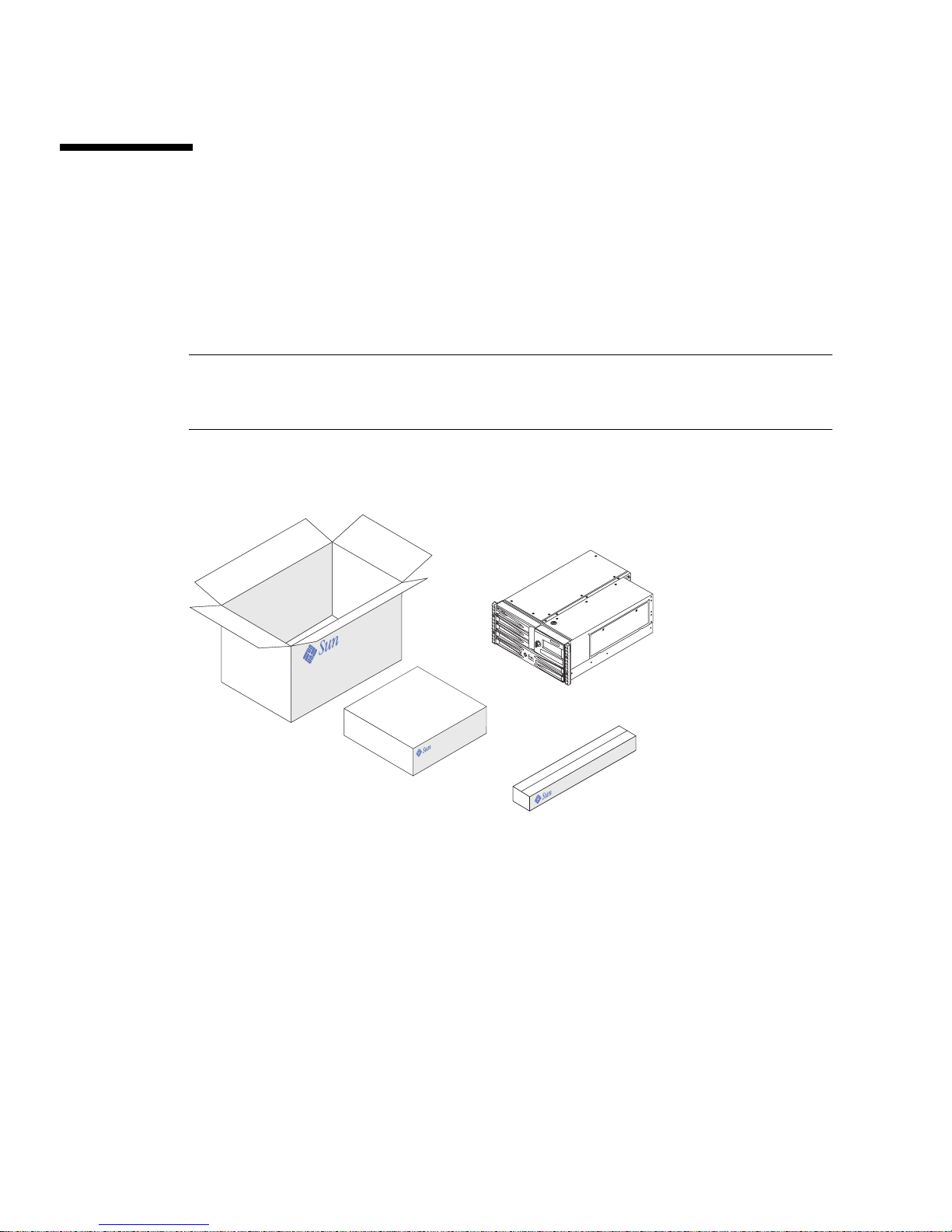
Standard features for Sun Fire V480 systems are installed at the factory. However, if
you ordered options such as a monitor, these will be shipped to you separately.
In addition, you should have received the media and documentation for all
appropriate system software. Check that you have received everything you ordered.
Note – Inspect the shipping carton for evidence of physical damage. If a shipping
carton is damaged, request that the carrier’s agent be present when the carton is
opened. Keep all contents and packing material for the agent’s inspection.
Unpacking instructions are printed on the outside of the shipping carton.
4 Sun Fire V480 Server Administration Guide • February 2002
Page 33

How to Install the Sun Fire V480 Server
Each step in this procedure refers you to a particular document or to a section of this
guide for instructions. Complete each step in the order listed.
The best way to begin your installation of a Sun Fire V480 server is by completing
the rackmounting and setup procedures in the Sun Fire V480 Server Setup and
Rackmounting Guide. This guide is shipped with your server in the ship kit box.
Before You Begin
The Sun Fire V480 server is a general-purpose server, which you can use for many
types of applications. Exactly how you set up your server depends on what you
want it to do.
This procedure is intended to be as “generic” as possible, so as to cover the needs of
most sites. Even so, you need to make certain decisions to complete the procedure:
■ On which network or networks do you intend the machine to operate?
You need to provide specific networking information about the server when you
install the Solaris operating environment. For background information about
network support, see “About the Network Interfaces” on page 54.
■ How do you want to use and configure the machine’s internal disks?
For background information about the internal disks, see “About the Internal
Disk Drives” on page 50.
■ What software do you intend to load?
Software included in the Solaris™ media kit or other software products may
impose certain disk space or disk partitioning requirements. Refer to the
documentation accompanying this software to determine those requirements.
Note – A minimal Solaris 8 installation requires at least 64 Mbytes of memory and
at least 1.7 Gbytes of disk space.
Once you have answered these questions, you are ready to begin the installation.
Chapter 1 Sun Fire V480 Server Installation 5
Page 34

What to Do
If you have completed the procedures in the Sun Fire V480 Server Setup and
Rackmounting Guide, begin this procedure at Step 7.
1. Verify that you have received all the parts of your system.
See “About the Parts Shipped to You” on page 4.
2. Install the system into either a 2-post rack or a 4-post cabinet, following all
instructions in the Sun Fire V480 Server Setup and Rackmounting Guide.
3. Set up a terminal or a console for installing your server.
You must set up a terminal or console in order to install the Solaris operating
environment and any application software.
You can either establish a tip connection from another server or use an ASCII
terminal connected to the serial port. See “About Communicating With the System”
on page 75 for background information, and then refer to the following procedures
in this guide:
■ “How to Access the System Console via tip Connection” on page 134
■ “How to Set Up an Alphanumeric Terminal as the System Console” on page 139
Note – To set up a serial connection using a Sun™ workstation or a dumb terminal,
insert the RJ-45 serial cable into the DB-25 adapter (Sun part number 530-2889-03)
supplied in the ship kit. Plug the adapter into the DB-25 serial connector on the
terminal or the Sun workstation. If you are using a network terminal server (NTS),
refer to “Reference for the Serial Port Connector” on page 214 to determine if you
need to use the adapter.
4. Install any optional components shipped with your system.
If you ordered options that are not factory-installed, see the Sun Fire V480 Server
Parts Installation and Removal Guide for installation instructions.
Note – All internal options (except disk drives and power supplies) must be
installed only by qualified service personnel. Installation procedures for these
components are covered in the Sun Fire V480 Server Parts Installation and Removal
Guide, which is included on the Sun Fire V480 Documentation CD.
Caution – The AC power cords provide a discharge path for static electricity, so
they must remain plugged in when you install or handle internal components.
6 Sun Fire V480 Server Administration Guide • February 2002
Page 35

5. Configure the network interface(s).
The Sun Fire V480 server provides two on-board Ethernet interfaces, which reside on
the system centerplane and conform to the IEEE 802.3z Ethernet standard. Two back
panel ports with RJ-45 connectors provide access to the on-board Ethernet interfaces.
Each interface configures itself automatically for either 10-Mbps, 100-Mbps, or
1000-Mbps operation depending on network characteristics.
A variety of supported Peripheral Component Interconnect (PCI) cards can provide
connections to additional Ethernet or other network types. For details about network
interface options and configuration procedures, see:
■ “About the Network Interfaces” on page 54
■ “How to Configure the Primary Network Interface” on page 150
■ “How to Configure Additional Network Interfaces” on page 152
Note – The Sun™ Remote System Control (RSC) card Ethernet and modem
interfaces are available only after you install the operating system software and the
RSC software. Consult the Sun Remote System Control (RSC) User’s Guide for more
details about configuring these interfaces.
6. Turn on power to your server.
See “How to Power On the System” on page 128. For information about the LED
status indicators that appear during power-up, see “LED Status Indicators” on
page 16.
7. Install and boot the Solaris operating environment software.
See the installation instructions provided with your Solaris software. You should
also consult the Solaris 8 Sun Hardware Platform Guide, which contains
platform-specific information about software installation.
8. Set any desired OpenBoot PROM configuration options.
You can control several aspects of system behavior through OpenBoot™ PROM
commands and configuration variables. For additional details, see Chapter 9,
“Configuring System Firmware” on page 159.
9. Load additional software from the Solaris media kit (optional).
The Solaris media kit (sold separately) includes several CDs containing software to
help you operate, configure, and administer your server. See the documentation
provided with the Solaris media kit for a complete listing of included software and
detailed installation instructions.
10. Load online documentation from the Sun Fire V480 Documentation CD.
You can copy the CD contents to a local or network disk drive, or view the
documentation directly from the CD. See the installation instructions that
accompany the CD in the Sun Fire V480 documentation set.
Chapter 1 Sun Fire V480 Server Installation 7
Page 36

11. Install and configure Sun Remote System Control (RSC) software from the Solaris
media kit (optional).
Sun RSC software is included on the Computer Systems Supplement CD for your
specific Solaris release. For installation instructions, see the Solaris 8 Sun Hardware
Platform Guide provided in the Solaris media kit. For information about configuring
and using RSC, see the Sun Remote System Control (RSC) User’s Guide provided with
the RSC software.
Once you install RSC software, you can configure the system to use RSC as the
system console. For detailed instructions, see “How to Redirect the System Console
to RSC” on page 165.
12. Install a local graphics terminal (optional).
After you have installed the Sun Fire V480 system and the Solaris operating
environment, if you prefer to use a graphics terminal as your system console, you
can install a graphics card and attach a monitor, mouse, and keyboard to the server.
See “How to Configure a Local Graphics Terminal as the System Console” on
page 141.
8 Sun Fire V480 Server Administration Guide • February 2002
Page 37

Part Two – Background
The five chapters within this part of the Sun Fire V480 Server Administration Guide
explain and illustrate in detail the various components of the server’s hardware,
software, and firmware. Use the chapters as a guided tour through the panels,
cables, cards, switches, and so forth that make up your server.
For detailed instructions on how to configure and administer the server, and how to
perform various diagnostic routines to resolve problems with the server, see the
chapters in Part Three – Instructions.
Chapters included in Part Two are:
■ Chapter 2 – System Overview
■ Chapter 3 – Hardware Configuration
■ Chapter 4 – Network Interfaces and System Firmware
■ Chapter 5 – System Administration Software
■ Chapter 6 – Diagnostic Tools
Page 38

Page 39

CHAPTER
2
System Overview
This chapter introduces you to the Sun Fire V480 server and describes some of its
features.
The following information is covered in this chapter:
■ “About the Sun Fire V480 Server” on page 12
■ “Locating Front Panel Features” on page 15
■ “Locating Back Panel Features” on page 20
■ “LED Status Indicators” on page 16
■ “About Reliability, Availability, and Serviceability Features” on page 22
11
Page 40

About the Sun Fire V480 Server
The Sun Fire V480 system is a high-performance, shared memory, symmetric
multiprocessing server that supports up to four UltraSPARC™ III processors. The
UltraSPARC III processor implements the SPARC™ V9 Instruction Set Architecture
(ISA) and the Visual Instruction Set (VIS™) extensions that accelerate multimedia,
networking, encryption, and Java™ processing.
The system, which is mountable in a 4-post or 2-post rack, measures 8.75 inches
(5 rack units - RU) high, 17.6 inches wide, and (without its plastic bezel) 24 inches
deep (22.225 cm x 44.7 cm x 60.96 cm). The system weighs approximately 88 lb
(39.9 kg).
Processing power is provided by up to two dual CPU/Memory boards. Each board
incorporates:
■ Two UltraSPARC III Cu 900-MHz processors
■ 8 Mbytes of local static random access memory (SRAM) external cache memory
per processor
■ Slots for up to 16 dual inline memory modules (DIMMs)—eight per processor
A fully configured system includes a total of four UltraSPARC III CPUs residing on
two CPU/Memory boards. For more information, see “About the CPU/Memory
Boards” on page 31.
System main memory is provided by up to 32 next-generation DIMMs, which
operate at a 75-MHz clock frequency. The system supports 256-Mbyte, 512-Mbyte,
and 1-Gbyte DIMMs. Total system memory is shared by all CPUs in the system and
ranges from a minimum of 2 Gbytes (one CPU/Memory board with eight 256-Mbyte
DIMMs) to a maximum of 32 Gbytes (two boards fully populated with 1-Gbyte
DIMMs). For more information about system memory, see “About the Memory
Modules” on page 32.
System I/O is handled by four separate Peripheral Component Interconnect (PCI)
buses. These industry-standard buses support all of the system’s on-board I/O
controllers in addition to six slots for PCI interface cards. Four of the PCI slots
operate at a 33-MHz clock rate, and two slots operate at either 33 or 66 MHz. All
slots comply with PCI Local Bus Specification Revision 2.1. For additional details,
see “About the PCI Cards and Buses” on page 35.
Internal disk storage is provided by up to two 1-inch, hot-pluggable, Fibre
Channel-Arbitrated Loop (FC-AL) disk drives. Both single and dual loop
configurations are supported. The basic system includes an FC-AL disk backplane
that accommodates two 36-Gbyte or 72-Gbyte disks. The system also supports
external mass-storage solutions, with an external FC-AL port located on the system’s
back panel. See “Locating Back Panel Features” on page 20.
12 Sun Fire V480 Server Administration Guide • February 2002
Page 41

The backplane provides dual-loop access to each of the FC-AL disk drives. One loop
is controlled by an on-board FC-AL controller integrated into the system
centerplane. The second loop is controlled by a PCI FC-AL host adapter card
(available as a system option). This dual-loop configuration enables simultaneous
access to internal storage via two different controllers, which increases available I/O
bandwidth. A dual-loop configuration can also be combined with multipathing
software to provide hardware redundancy and failover capability. Should a
component failure render one loop inaccessible, the software can automatically
switch data traffic to the second loop to maintain system availability. For more
information about the system’s internal disk array, see “About FC-AL Technology”
on page 47, “About the FC-AL Backplane” on page 48, and “About the FC-AL Host
Adapters” on page 50.
External multidisk storage subsystems and redundant array of independent disks
(RAID) storage arrays can be supported by installing single-channel or multichannel
PCI host adapter cards along with the appropriate system software. Software drivers
supporting FC-AL and other types of devices are included in the Solaris operating
environment.
The system provides two on-board Ethernet host PCI adapters, which support
several modes of operations at 10, 100, and 1000 megabits per second (Mbps).
Additional Ethernet interfaces or connections to other network types can be
provided by installing the appropriate PCI interface cards. Multiple network
interfaces can be combined with multipathing software to provide hardware
redundancy and failover capability. Should one of the interfaces fail, the software
can automatically switch all network traffic to an alternate interface to maintain
network availability. For more information about network connections, see “How to
Configure the Primary Network Interface” on page 150 and “How to Configure
Additional Network Interfaces” on page 152.
The Sun Fire V480 server provides a serial communication port, which you can
access through an RJ-45 connector located on the system’s back panel. For more
information, see “About the Serial Port” on page 51.
The back panel also provides two Universal Serial Bus (USB) ports for connecting
USB peripheral devices such as modems, printers, scanners, digital cameras, or a
Sun Type 6 USB keyboard and mouse. The USB ports support both isochronous
mode and asynchronous mode. The ports enable data transmission at speeds of 12
Mbps. For additional details, see “About the USB Ports” on page 52.
The local system console device can be either a standard ASCII character terminal or
a local graphics console. The ASCII terminal connects to the system’s serial port,
while a local graphics console requires installation of a PCI graphics card, monitor,
USB keyboard, and mouse. You can also administer the system from a remote
workstation connected to the Ethernet or from a Sun Remote System Control (RSC)
console.
Chapter 2 System Overview 13
Page 42

RSC is a secure server management tool that lets you monitor and control your
server over a serial line, through a modem, or over a network. RSC provides remote
system administration for geographically distributed or physically inaccessible
systems. RSC software works in conjunction with the RSC card included in all Sun
Fire V480 servers.
The RSC card runs independently of the host server, and operates off of 5-volt
standby power from the system’s power supplies. The card also includes a battery
that provides approximately 30 minutes of backup power in the event of a power
failure. Together these features allow RSC to serve as a “lights out” management tool
that continues to function even when the server operating system goes offline, the
server is powered off, or a power outage occurs. For additional details, see “About
the Sun Remote System Control Card” on page 38.
The basic system includes two 1184-watt power supplies, each with two internal
fans. The power supplies are plugged directly into one power distribution board
(PDB). One power supply provides sufficient power for a maximally configured
system. The second power supply provides “1 + 1” redundancy, allowing the system
to continue operating should the first power supply fail. A power supply in a
redundant configuration is hot-swappable, so that you can remove and replace a
faulty power supply without shutting down the operating system or turning off the
system power. For more information about the power supplies, see “About the
Power Supplies” on page 43.
System reliability, availability, and serviceability (RAS) are enhanced by features that
include hot-pluggable disk drives and redundant, hot-swappable power supplies. A
full list of RAS features is in the section, “About Reliability, Availability, and
Serviceability Features” on page 22.
14 Sun Fire V480 Server Administration Guide • February 2002
Page 43
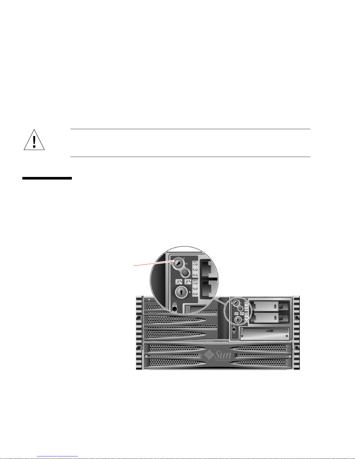
Locating Front Panel Features
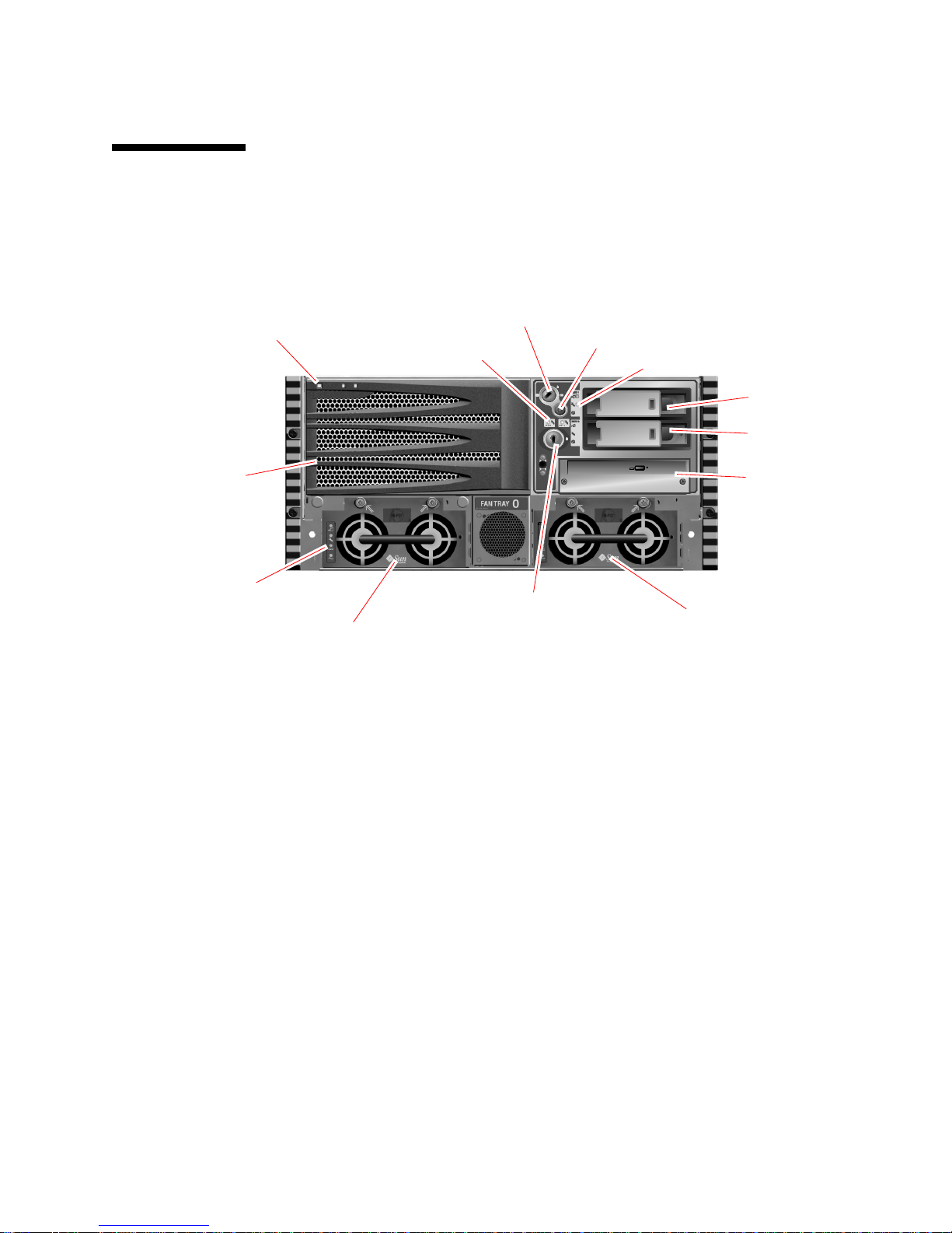
The illustration below shows the system features that you can access from the front
panel. In the illustration, the media door (upper right) and the power supply access
panel (bottom) are removed.
System status LEDs
Fan Tray 0
Power supply status LEDs
Power Supply 0
FIGURE 2-1 Sun Fire V480 Server Front Panel Features
For information about front panel controls and indicators, see “LED Status
Indicators” on page 16. Also see the Sun Fire V480 Server Parts Installation and
Removal Guide for more detailed information and illustrations.
System control switch
Fan tray LEDs
Security lock
Power button
Disk drive status LEDs
Disk Drive 1
Disk Drive 0
DVD-ROM drive
Power Supply 1
Security Lock and Top Panel Lock
In addition to the security lock on the system’s front panel, a top panel lock on the
top of the system controls entry to both the PCI access panel and the CPU access
panel. When the key is in the upright position, the media door is unlocked.
However, even if the top panel lock is in the locked position, thereby locking both
the PCI and CPU access panels, you can still unlock the media door security lock and
gain access to the disk drives, power supplies, and Fan Tray 0. If the media door is
locked and the power supply access panel is in place, you will not be able to gain
access to the power supplies, disk drives, and Fan Tray 0—even if the PCI access
panel is unlocked.
Chapter 2 System Overview 15
Page 44

Note – The same key operates the security lock, the system control switch (see
“System Control Switch” on page 18), and the top panel lock for the PCI and CPU
access panels.
The standard system is configured with two power supplies, which are accessible
from the front of the system. LED indicators display power status. See “LED Status
Indicators” on page 16 for additional details.
LED Status Indicators
Several LED status indicators on both the front and back panels provide general
system status, alert you to system problems, and help you to determine the location
of system faults.
At the top left of the system as you look at its front are three general system LEDs.
Two of these LEDs, the system Fault LED and the Power/OK LED, provide a snapshot
of the overall system status. One LED—the Locator LED—helps you to locate a
specific system quickly, even though it may be one of dozens or even scores of
systems in a room. The front panel Locator LED is at the far left in the cluster. The
Locator LED is lit by command from the administrator. For instructions, see “How to
Operate the Locator LED” on page 174.
Other LEDs located on the front of the system work in conjunction with specific fault
LED icons. For example, a fault in the disk subsystem illuminates a disk drive fault
LED in the center of the LED cluster that is next to the affected disk drive. Since all
front panel status LEDs are powered by the system’s 5-volt standby power source,
fault LEDs remain lit for any fault condition that results in a system shutdown.
Locator, Fault, and Power/OK LEDs are also found at the upper-left corner of the
back panel. Also located on the back panel are LEDs for the system’s two power
supplies and RJ-45 Ethernet ports.
See
FIGURE 2-1, “Sun Fire V480 Server Front Panel Features” on page 15 and
FIGURE 2-3, “Sun Fire V480 Server Back Panel Features” on page 20 for locations of
the front panel and back panel LEDs.
During system startup, LEDs are toggled on and off to verify that each one is
working correctly.
The following tables list and describe the LEDs on the front panel: system LEDs, fan
tray LEDs, and hard disk drive LEDs.
16 Sun Fire V480 Server Administration Guide • February 2002
Page 45

Listed from left to right, the system LEDs operate as described in the following table.
TABLE 2-1 System LEDs
Name Description
Locator This white LED is lit by Sun Management Center or Sun
Remote System Control software, or by Solaris command,
to locate a system.
Fault This amber LED lights to indicate that the system hardware
or software has detected a system fault.
Power/OK This green LED lights when the main power (48 VDC) is
on.
The following table describes the fan tray LEDs.
TABLE 2-2 Fan Tray LEDs
Name Description
Fan Tray 0 (FT 0) This amber LED lights whenever a fault is detected in the
CPU fans.
Fan Tray 1 (FT 1) This amber LED lights whenever a fault is detected in the
PCI fans.
The following table describes the disk drive LEDs.
TABLE 2-3 Hard Disk Drive LEDs
Name Description
OK-to-Remove This blue LED lights when it is safe to remove the hard disk
drive from the system
Fault This amber LED lights whenever the system software
detects a fault in the monitored hard disk drive. Note that
the system Fault LED on the front panel will also be lit
when this occurs.
Activity This green LED lights whenever a disk is present in the
monitored drive slot. This LED blinks slowly to indicate that
the drive is spinning up or down, and quickly to indicate
disk activity.
Further details about the diagnostic use of LEDs are discussed separately in the
section, “How to Isolate Faults Using LEDs” on page 176.
Chapter 2 System Overview 17
Page 46
Power Button
The system Power button is recessed to prevent accidentally turning the system on
or off. The ability of the Power button to turn the system on or off is controlled by
the system control switch. See the section, “System Control Switch” on page 18.
If the operating system is running, pressing and releasing the Power button initiates
a graceful software system shutdown. Pressing and holding in the Power button for
five seconds causes an immediate hardware shutdown.
Caution – Whenever possible, you should use the graceful shutdown method.
Forcing an immediate hardware shutdown may cause disk drive corruption and loss
of data.
System Control Switch
The four-position system control switch on the system’s status and control panel
controls the power-on modes of the system and prevents unauthorized users from
powering off the system or reprogramming system firmware. In the following
illustration, the system control switch is in the Locked position.
System control switch
FIGURE 2-2 Four-Position System Control Switch in Locked Position
18 Sun Fire V480 Server Administration Guide • February 2002
Page 47
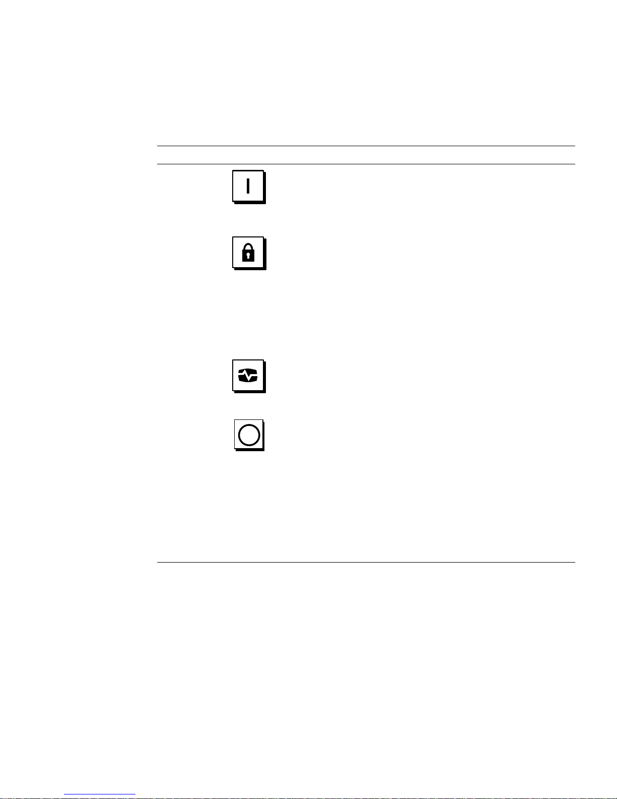
The following table describes the function of each system control switch setting.
TABLE 2-4 System Control Switch Settings
Position Icon Description
Normal This setting enables the system Power button to power the
system on or off. If the operating system is running, pressing
and releasing the Power button initiates a graceful software
system shutdown. Pressing and holding the Power button in
for five seconds causes an immediate hardware power off.
Locked This setting disables the system Power button to prevent
unauthorized users from powering the system on or off. It also
disables the keyboard L1-A (Stop-A) command, terminal
Break key command, and ~# tip window command,
preventing users from suspending system operation to access
the system ok prompt.
The Locked setting, used for normal day-to-day operations,
also prevents unauthorized programming of the system boot
PROM.
Diagnostics This setting forces the power-on self-test (POST) and
OpenBoot Diagnostics software to run during system startup
and system resets. The Power button functions the same as
when the system control switch is in the Normal position.
Forced Off This setting forces the system to power off immediately and to
enter 5-volt standby mode. It also disables the system Power
button. You may want to use this setting when AC power is
interrupted and you do not want the system to restart
automatically when power is restored. With the system control
switch in any other position, if the system were running prior
to losing power, it restarts automatically once power is
restored.
The Forced Off setting also prevents an RSC session from
restarting the system. However, the RSC card continues to
operate using the system’s 5-volt standby power.
Chapter 2 System Overview 19
Page 48
PCI card slots
RSC ports:
Serial
Modem
Ethernet
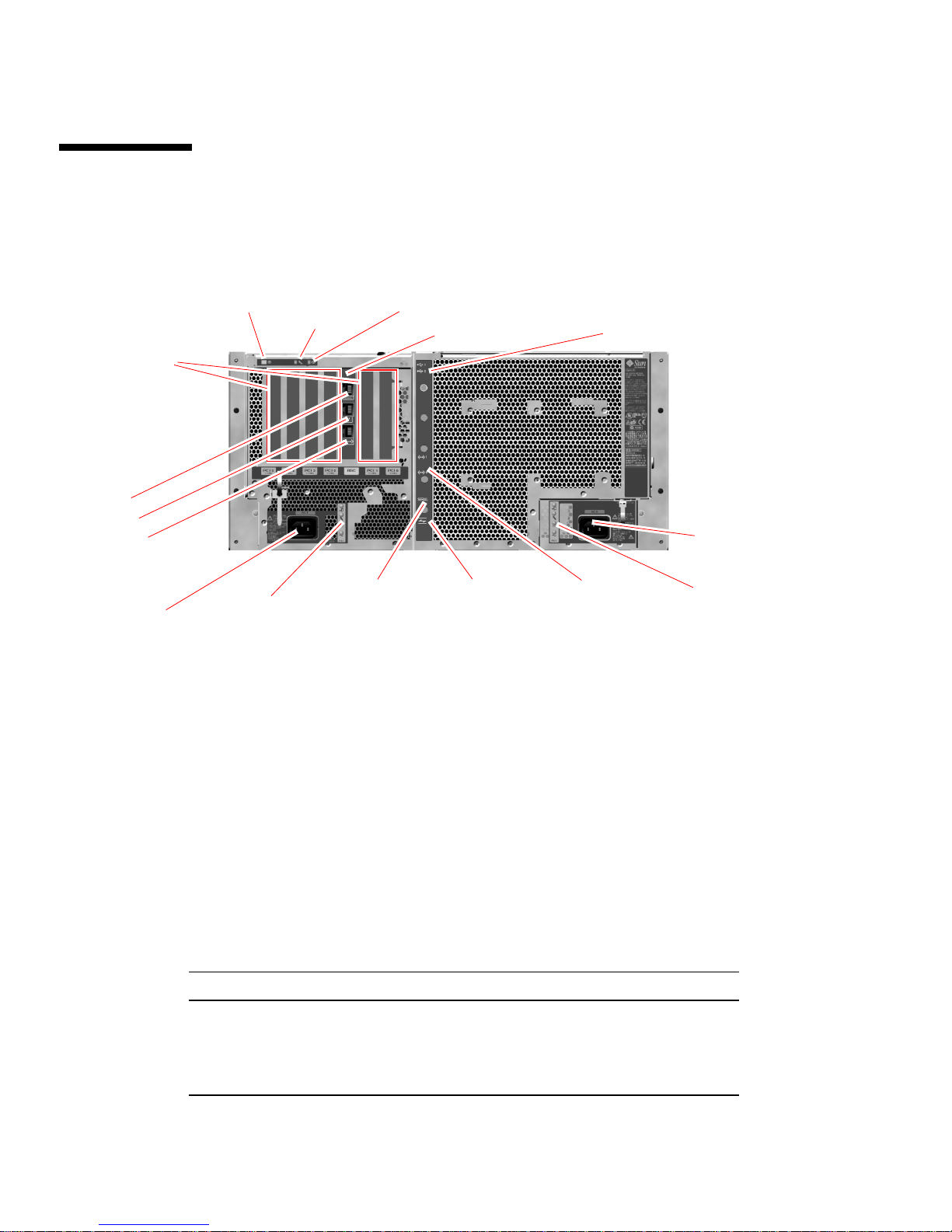
Locating Back Panel Features
The following figure shows the system features that you can access from the back
panel.
Power/OK LEDLocator LED
Fault LED
RSC card
USB ports
(
see Figure 2-4)
AC input for
Power Supply 0
AC input for
Power Supply 1
Serial port FC-AL port
Power Supply 1
status LEDs
FIGURE 2-3 Sun Fire V480 Server Back Panel Features
(The ports above not visible in this illustration;
see Figure 2-4.)
Ethernet ports
Power Supply 0
status LEDs
Main system LEDs—Locator, Fault, and Power/OK—are repeated on the back panel.
(See
TABLE 2-1, TABLE 2-2, and TABLE 2-3 for descriptions of front panel LEDs.) In
addition, the back panel includes LEDs that display the status of each of the two
power supplies and both on-board Ethernet connections. Two LEDs located on each
Ethernet RJ-45 connector display the status of Ethernet activity. Each power supply
is monitored by four LEDs.
Details of the diagnostic use of LEDs are discussed separately in the section, “How
to Isolate Faults Using LEDs” on page 176.
TABLE 2-5 lists and describes the Ethernet LEDs on the system’s back panel.
TABLE 2-5 Ethernet LEDs
Name Description
Ethernet
Activity
This amber LED lights to indicate that data is either being
transmitted or received by the particular port.
Ethernet Link
Up
20 Sun Fire V480 Server Administration Guide • February 2002
This green LED lights when a link is established at the
particular port with its link partner.
Page 49
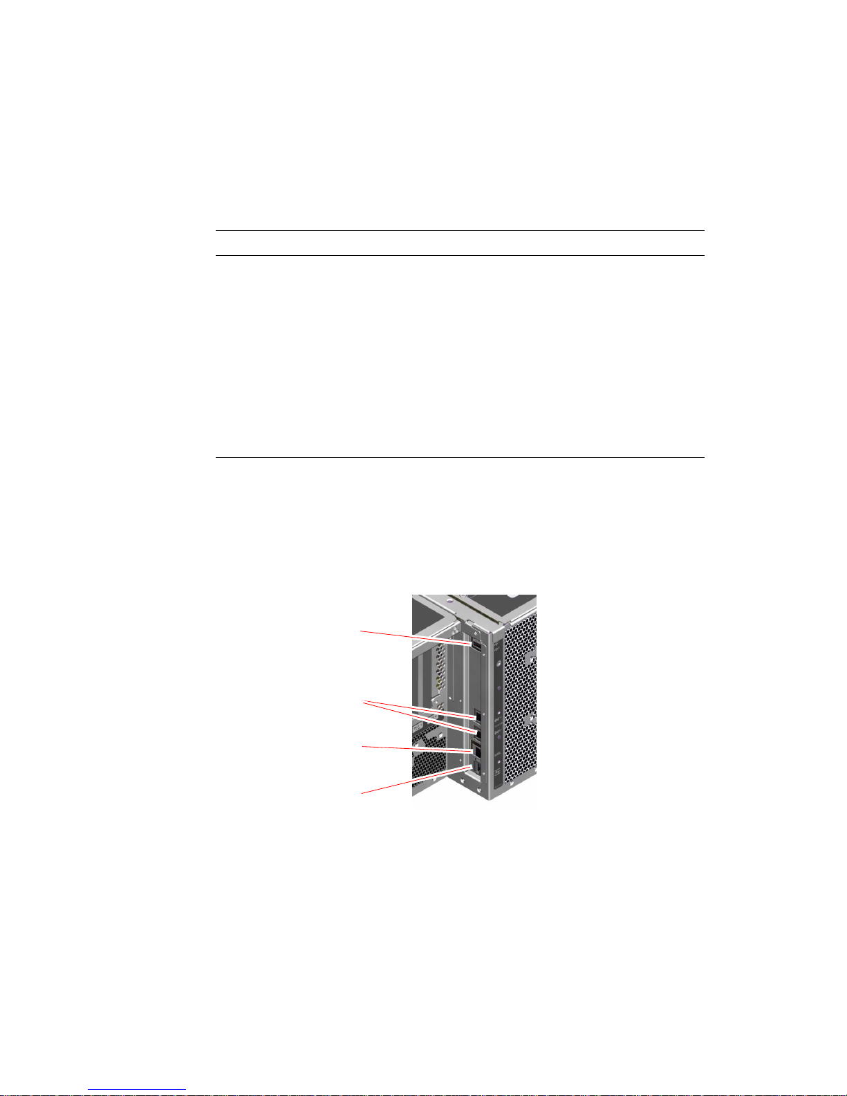
TABLE 2-6 lists and describes the power supply LEDs on the system’s back panel.
TABLE 2-6 Power Supply LEDs
Name Description
Power supply
OK-to-Remove
Power supply
Fault
This blue LED lights when it is safe to remove the power
supply from the system.
This amber LED lights whenever the power supply’s
internal microcontroller detects a fault in the monitored
power supply. Note that the Fault LED on the front panel
will also be lit when this occurs.
Power supply
DC Present
Power supply
AC Present
This green LED lights when the power supply is on and
outputting regulated power within specified limits.
This green LED lights whenever a proper AC voltage
source is input to the power supply.
Also accessible from the back panel are:
■ Inlets for both AC power supplies
■ Six PCI card slots
■ One Sun Remote System Control (RSC) card slot
■ Six external data ports: USB, serial, Ethernet, and FC-AL (see FIGURE 2-4)
USB ports (2)
Ethernet ports
FIGURE 2-4 Back Panel External Ports
Serial port
FC-AL port
Chapter 2 System Overview 21
Page 50

About Reliability, Availability, and
Serviceability Features
Reliability, availability, and serviceability (RAS) are aspects of a system’s design that
affect its ability to operate continuously and to minimize the time necessary to
service the system. Reliability refers to a system’s ability to operate continuously
without failures and to maintain data integrity. System availability refers to the
percentage of time that a system remains accessible and usable. Serviceability relates
to the time it takes to restore a system to service following a system failure. Together,
reliability, availability, and serviceability features provide for near continuous
system operation.
To deliver high levels of reliability, availability and serviceability, the Sun Fire V480
system offers the following features:
■ Hot-pluggable disk drives
■ Redundant, hot-swappable power supplies
■ Environmental monitoring and fault protection
■ Automatic system recovery (ASR) capabilities
■ Multiplexed I/O (MPxIO)
■ Sun Remote System Control (RSC) remote “lights out” management capability
■ Hardware watchdog mechanism and XIR
■ Dual-loop enabled FC-AL subsystem
■ Support for disk and network multipathing with automatic failover capability
■ Error correction and parity checking for improved data integrity
■ Easy access to all internal replaceable components
■ Full in-rack serviceability by extending the slides
Hot-Pluggable and Hot-Swappable Components
Sun Fire V480 hardware is designed to support hot-plugging of internal disk drives
and hot-swapping of power supplies. With the proper software support, you can
install or remove these components while the system is running. Hot-plug and
hot-swap technology significantly increases the system’s serviceability and
availability, by providing the ability to:
■ Increase storage capacity dynamically to handle larger work loads and improve
system performance
■ Replace disk drives and power supplies without service disruption
For additional information about the system’s hot-pluggable and hot-swappable
components—including a discussion of the differences between the two
practices—see “About Hot-Pluggable and Hot-Swappable Components” on page 30.
22 Sun Fire V480 Server Administration Guide • February 2002
Page 51

1+1 Power Supply Redundancy
The system features two hot-swappable power supplies, either of which is capable of
handling the system’s entire load. Thus, the system provides “1+1” redundancy,
allowing the system to continue operating should one of the power supplies or its
AC power source fail. For more information about power supplies, redundancy, and
configuration rules, see “About the Power Supplies” on page 43.
Environmental Monitoring and Control
The Sun Fire V480 system features an environmental monitoring subsystem
designed to protect against:
■ Extreme temperatures
■ Lack of adequate airflow through the system
■ Power supply failures
Monitoring and control capabilities reside at the operating system level as well as in
the system’s boot PROM firmware. This ensures that monitoring capabilities remain
operational even if the system has halted or is unable to boot.
The environmental monitoring subsystem uses an industry-standard I
2
I
C bus is a simple two-wire serial bus, used throughout the system to allow the
2
C bus. The
monitoring and control of temperature sensors, fans, power supplies, status LEDs,
and the front panel system control switch.
Temperature sensors are located throughout the system to monitor the ambient
temperature of the system and the temperature of several ASICs. The monitoring
subsystem polls each sensor and uses the sampled temperatures to report and
respond to any overtemperature or undertemperature conditions.
The hardware and software together ensure that the temperatures within the
enclosure do not stray outside predetermined “safe operation” ranges. If the
temperature observed by a sensor falls below a low-temperature warning threshold
or rises above a high-temperature warning threshold, the monitoring subsystem
software lights the system Fault LED on the front status and control panel.
All error and warning messages are displayed on the system console (if one is
attached) and are logged in the /var/adm/messages file. Front panel Fault LEDs
remain lit after an automatic system shutdown to aid in problem diagnosis.
The monitoring subsystem is also designed to detect fan failures. The system
features two fan trays, which include a total of five individual fans. If any fan fails,
the monitoring subsystem detects the failure and generates an error message and
logs it in the /var/adm/messages file, lights the appropriate fan tray LED, and
lights the system Fault LED.
Chapter 2 System Overview 23
Page 52

The power subsystem is monitored in a similar fashion. Polling the power supply
status registers periodically, the monitoring subsystem indicates the status of each
supply’s DC outputs.
If a power supply problem is detected, an error message is displayed on the system
console and logged in the /var/adm/messages file. Additionally, LEDs located on
each power supply are illuminated to indicate failures.
Automatic System Recovery
The system provides for automatic system recovery (ASR) from the following types
of hardware component failures:
■ CPUs
■ Memory modules
■ PCI buses and cards
■ FC-AL subsystem
■ Ethernet interface
■ USB interfaces
■ Serial interface
The ASR features allow the system to resume operation after experiencing certain
non-fatal hardware faults or failures. Automatic self-test features enable the system
to detect failed hardware components and an auto-configuring capability designed
into the system’s boot firmware allows the system to unconfigure failed components
and restore system operation. As long as the system is capable of operating without
the failed component, the ASR features will enable the system to reboot
automatically, without operator intervention.
During the power-on sequence, if a faulty component is detected, the component is
effectively disabled and, if the system remains capable of functioning, the boot
sequence continues. In a running system, some types of failures (such as a processor
failure) can bring down the system. If this happens, the ASR functionality enables
the system to reboot immediately if it is possible for the system to run without the
failed component. This prevents a faulty hardware component from keeping the
entire system down or causing the system to crash repeatedly.
Note – ASR functionality is not enabled until you activate it. Control over the
system’s ASR functionality is provided by a number of OpenBoot PROM commands
and configuration variables. For additional details, see “About Automatic System
Recovery” on page 63.
24 Sun Fire V480 Server Administration Guide • February 2002
Page 53

MPxIO
Multiplexed I/O (MPxIO), a feature found in the Solaris 8 operating environment, is
a native multipathing solution for storage devices such as Sun StorEdge™ disk
arrays. MPxIO provides:
■ Host-level multipathing (there is no multipathing support for boot devices)
■ Physical host controller interface (pHCI) support
■ Sun StorEdge T3 and Sun StorEdge A5x00 support
■ Load balancing
■ Coexistence with Alternate Pathing (AP) and Dynamic Multipathing (DMP)
For further details about MPxIO, see “Multiplexed I/O (MPxIO)” on page 71. Also
consult your Solaris documentation.
Sun Remote System Control
Sun Remote System Control (RSC) software is a secure server management tool that
lets you monitor and control your server over a serial line, over a modem, or over a
network. RSC provides remote system administration for geographically distributed
or physically inaccessible systems. The RSC software works with the RSC card on
the Sun Fire V480 system PCI riser board. The RSC card provides modem and
private Ethernet connections to a remote console, and a serial connection to a local
alphanumeric terminal.
Once RSC is configured to manage your server, you can use it to run diagnostic tests,
view diagnostic and error messages, reboot your server, and display environmental
status information from a remote console. Even if the operating system is down, RSC
can send an email or pager alert about power failures, hardware failures, or other
important events that may be occurring on your server.
RSC provides the following features:
■ Remote system monitoring and error reporting (including diagnostic output)
■ Remote reboot, power-on, power-off, and reset functions
■ Ability to monitor system environmental conditions remotely
■ Ability to run diagnostic tests from a remote console
■ Ability to capture and store the console log, which you may review or replay
later, remotely
■ Remote event notification for overtemperature conditions, power supply failures,
fatal system errors, system shutdown, or system reset
■ Remote access to detailed event logs
■ Remote console functions via modem, Ethernet, or serial port
Chapter 2 System Overview 25
Page 54

For more details about RSC hardware, see:
■ “About the Sun Remote System Control Card” on page 38
For information about installing, configuring, and using RSC, see “How to Monitor
the System Using RSC” on page 195 and the Sun Remote System Control (RSC) User’s
Guide provided with the RSC software.
Hardware Watchdog Mechanism and XIR
To detect and respond to system hang conditions, the Sun Fire V480 system features
a hardware watchdog mechanism—a hardware timer that is continually reset as long
as the operating system is running. In the event of a system hang, the operating
system is no longer able to reset the timer. The timer will then expire and cause an
automatic “externally initiated reset” (XIR), eliminating the need for operator
intervention. When the watchdog mechanism issues the XIR, debug information is
dumped to the system console.
Note – The hardware watchdog mechanism is not activated until you enable it. See
“How to Enable the Watchdog Mechanism and Its Options” on page 162 for
instructions.
The XIR feature is also available for you to invoke manually, by way of your RSC
console. You use the xir command manually when the system is absolutely hung
and an L1-A (Stop-A) keyboard command does not work. When you issue the xir
command manually by way of RSC, the system is immediately returned to the
OpenBoot™ PROM (OBP) ok prompt. From there, you can use OBP commands to
debug the system.
Dual-Loop Enabled FC-AL Subsystem
The system’s dual-ported Fibre Channel-Arbitrated Loop (FC-AL) disk drives and
dual-loop enabled FC-AL backplane may be combined with an optional PCI FC-AL
host adapter card to provide for fault tolerance and high availability of data. This
dual-loop configuration allows each disk drive to be accessed through two separate
and distinct data paths, providing both increased bandwidth and hardware
redundancy; that is, dual-loop configuration provides the ability to sustain
component failures in one path by switching all data transfers to an alternate path.
The FC-AL subsystem is described in greater detail in:
■ “About FC-AL Technology” on page 47
■ “About the FC-AL Backplane” on page 48
■ “About the FC-AL Host Adapters” on page 50
26 Sun Fire V480 Server Administration Guide • February 2002
Page 55

Support for RAID Storage Configurations
By attaching one or more external storage devices to the Sun Fire V480 server, you
can use a software RAID application such as Solstice DiskSuite™ or VERITAS
Volume Manager to configure system disk storage in a variety of different RAID
levels. Configuration options include RAID 0 (striping), RAID 1 (mirroring), RAID
0+1 (striping plus mirroring), RAID 1+0 (mirroring plus striping), and RAID 5
(striping with interleaved parity). You choose the appropriate RAID configuration
based on the price, performance, and reliability and availability goals for your
system. You can also configure one or more drives to serve as “hot spares” to fill in
automatically for a defective drive in the event of a disk failure.
For more information, see “About Volume Management Software” on page 70.
Error Correction and Parity Checking
Error correcting code (ECC) is used on all internal system data paths to ensure high
levels of data integrity. All data that moves between processors, memory, and PCI
bridge chips have end-to-end ECC protection.
The system reports and logs correctable ECC errors. A correctable ECC error is any
single-bit error in a 128-bit field. Such errors are corrected as soon as they are
detected. The ECC implementation can also detect double-bit errors in the same
128-bit field and multiple-bit errors in the same nibble (4 bits).
In addition to providing ECC protection for data, the system offers parity protection
on all system address buses. Parity protection is also used on the PCI and SCSI
buses, and in the UltraSPARC III CPU’s internal and external caches.
Chapter 2 System Overview 27
Page 56

28 Sun Fire V480 Server Administration Guide • February 2002
Page 57

CHAPTER
3
Hardware Configuration
This chapter provides hardware configuration information for the Sun Fire V480
server.
The following topics are covered in this chapter:
■ “About Hot-Pluggable and Hot-Swappable Components” on page 30
■ “About the CPU/Memory Boards” on page 31
■ “About the Memory Modules” on page 32
■ “About the PCI Cards and Buses” on page 35
■ “About the Sun Remote System Control Card” on page 38
■ “About Hardware Jumpers” on page 40
■ “About the Power Supplies” on page 43
■ “About the Fan Trays” on page 45
■ “About FC-AL Technology” on page 47
■ “About the FC-AL Backplane” on page 48
■ “About the FC-AL Host Adapters” on page 50
■ “About the Internal Disk Drives” on page 50
■ “About the HSSDC FC-AL Port” on page 49
■ “About the USB Ports” on page 52
For configuration information about network interfaces, see:
■ “How to Configure the Primary Network Interface” on page 150
■ “How to Configure Additional Network Interfaces” on page 152
29
Page 58

About Hot-Pluggable and
Hot-Swappable Components
In a Sun Fire V480 system, the FC-AL disk drives are hot-pluggable components and
the power supplies are hot-swappable. (No other component of the system is either
hot-pluggable or hot-swappable.) Hot-pluggable components are those that you can
install or remove while the system is running, without affecting the rest of the
system’s capabilities. However, in many cases, you must prepare the operating
system prior to the hot-plug event by performing certain system administration
tasks. The power supplies require no such preparation and are called hot-swappable
components. These components can be removed or inserted at any time without
preparing the operating system in advance. While all hot-swappable components are
hot-pluggable, not every hot-pluggable component is hot-swappable.
Each component is discussed in more detail in the sections that follow. (Not
discussed here are any devices that you may attach to the USB port, which are
generally hot-pluggable.)
Caution – The RSC card is not a hot-pluggable component. Before installing or
removing an RSC card, you must power off the system and disconnect all AC power
cords.
Power Supplies
Sun Fire V480 power supplies are hot-swappable—they can be removed or inserted
at any time without prior software preparation. Keep in mind that a power supply is
hot-swappable only as long as it is part of a redundant power configuration—a
system configured with both power supplies in working condition. (Logically, you
cannot “hot-swap” a power supply if it is the only one in the system that still
works.)
Unlike other hot-pluggable devices, you can install or remove a power supply while
the system is operating at the ok prompt when the blue “OK-to-Remove” LED is lit.
For additional information, see “About the Power Supplies” on page 43. For
instructions on removing or installing power supplies, see the Sun Fire V480 Server
Parts Installation and Removal Guide.
30 Sun Fire V480 Server Administration Guide • February 2002
Page 59
Disk Drives
Sun Fire V480 internal disk drives are hot-pluggable. However, certain software
preparations are required prior to removing or installing a drive. To perform Sun
Fire V480 disk drive hot-plug operations, you use the Solaris luxadm utility. The
luxadm utility is a command-line tool for managing intelligent storage arrays such
as Sun StorEdge A5x00 series disk arrays or Sun Fire V480 internal storage arrays.
For more information about luxadm, see the luxadm man page. For complete disk
hot-plug procedures, see the Sun Fire V480 Server Parts Installation and Removal Guide.
Caution – When hot-plugging a disk drive, first ensure that the drive’s
OK-to-Remove LED is lit. Then, after disconnecting the drive from the FC-AL
backplane, allow 30 seconds or so for the drive to spin down completely before
removing it.
About the CPU/Memory Boards
The system centerplane provides slots for up to two CPU/Memory boards. Each
CPU/Memory board incorporates two UltraSPARC III Cu 900-MHz processors, with
8 Mbytes of static random access memory (SRAM) external cache memory per
processor, and slots for up to 16 memory modules. The external cache memory
cannot be upgraded.
The memory module slots are labeled A and B. The CPUs in the system are
numbered from 0 to 3, depending on the slot where each CPU resides. For example,
a CPU/Memory board installed in slot B always contains CPUs 1 and 3, even if there
are no other CPU/Memory boards installed in the system.
Note – CPU/Memory boards on a Sun Fire V480 system are not hot-pluggable.
The UltraSPARC III processor is a high-performance, highly integrated superscalar
processor implementing the SPARC V9 64-bit architecture. The UltraSPARC III
processor supports both 2D and 3D graphics, as well as image processing, video
compression and decompression, and video effects through the sophisticated Visual
Instruction Set (VIS) extension. VIS provides high levels of multimedia performance,
including real-time video compression and decompression and two streams of
MPEG-2 decompression at full broadcast quality with no additional hardware
support.
Chapter 3 Hardware Configuration 31
Page 60

The Sun Fire V480 server employs a shared-memory multiprocessor architecture
with all processors sharing the same physical address space. The system processors,
main memory, and I/O subsystem communicate via a high-speed system
interconnect bus, operating at a clock rate of 150 MHz. In a system configured with
multiple CPU/Memory boards, all main memory is accessible from any processor
over the system bus. The main memory is logically shared by all processors and I/O
devices in the system.
For information about memory modules and memory configuration guidelines, see
“About the Memory Modules” on page 32.
About the Memory Modules
The Sun Fire V480 server uses 3.3-volt, high-capacity dual inline memory modules
(DIMMs). The DIMMs are built with synchronous dynamic random access memory
(SDRAM) chips that operate at a 75-MHz clock frequency. The system supports
DIMMs with 256-Mbyte, 512-Mbyte, and 1-Gbyte capacities.
Each CPU/Memory board contains slots for 16 DIMMs. Total system memory ranges
from a minimum of 2 Gbytes (one CPU/Memory board with eight 256-Mbyte
DIMMs) to a maximum of 32 Gbytes (two boards fully populated with 1-Gbyte
DIMMs).
Within each CPU/Memory board, the 16 DIMM slots are organized into groups of
four. The system reads from, or writes to, all four DIMMs in a group simultaneously.
DIMMs, therefore, must be added in sets of four.
and DIMM groups on a Sun Fire V480 CPU/Memory board. Every fourth slot
belongs to the same DIMM group. The four groups are designated A0, A1, B0, and
B1.
FIGURE 3-1 shows the DIMM slots
32 Sun Fire V480 Server Administration Guide • February 2002
Page 61
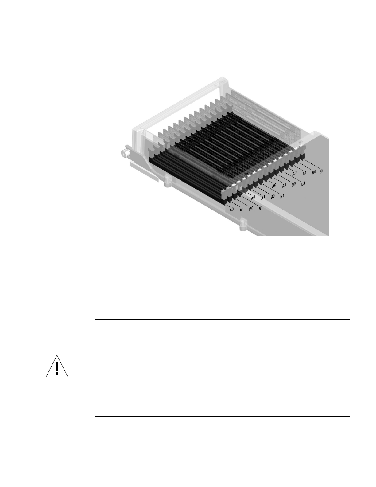
FIGURE 3-1 Memory Module Groups A0, A1, B0, B1
You must physically remove a CPU/Memory board from the system before you can
install or remove DIMMs. The DIMMs must be added four-at-a-time within the same
DIMM group, and each group used must have four identical DIMMs installed—that
is, all four DIMMs in the group must be from the same manufacturing vendor and
must have the same capacity (for example, four 256-Mbyte DIMMs, four 512-Mbyte
DIMMs, or four 1-Gbyte DIMMs).
Note – Each CPU/Memory board must be populated with a minimum of eight
DIMMs, installed in groups A0 and B0.
Caution – DIMMs are made of electronic components that are extremely sensitive
to static electricity. Static from your clothes or work environment can destroy the
modules. Do not remove a DIMM from its antistatic packaging until you are ready to
install it on the system board. Handle the modules only by their edges. Do not touch
the components or any metal parts. Always wear an antistatic grounding strap when
you handle the modules. For more information, see “How to Avoid Electrostatic
Discharge” on page 126.
Chapter 3 Hardware Configuration 33
Page 62

Memory Interleaving
You can maximize the system’s memory bandwidth by taking advantage of its
memory interleaving capabilities. Sun Fire V480 systems support two-way, four-way,
and eight-way memory interleaving. In most cases, higher interleaving factors result
in greater system performance. However, actual performance results may vary
depending on the system application.
The system’s interleaving capabilities are summarized as follows:
■ Memory interleaving is limited to memory within the same CPU/Memory board.
Memory is not interleaved across CPU/Memory boards.
■ Eight-way interleaving occurs automatically when all 16 DIMM slots in a
CPU/Memory board are filled with identical capacity DIMMs (16 identical
DIMMs).
■ Four-way interleaving occurs automatically between any two DIMM groups that
are configured identically (eight identical capacity DIMMs).
■ Two-way interleaving occurs automatically in any DIMM group where the DIMM
capacities do not match the capacities used in any other group.
Independent Memory Subsystems
Each Sun Fire V480 CPU/Memory board contains two independent memory
subsystems (one per UltraSPARC III CPU). Memory controller logic incorporated
into the UltraSPARC III CPU allows each CPU to control its own memory
subsystem. One CPU controls DIMM groups A0 and A1, while the other CPU
controls DIMM groups B0 and B1.
The Sun Fire V480 system uses a shared memory architecture. During normal system
operations, the total system memory is shared by all CPUs in the system. However,
in the event of a CPU failure, the two DIMM groups associated with the failed CPU
become unavailable to the other CPUs in the system.
TABLE 3-1 shows the association between the CPUs and their corresponding DIMM
groups.
TABLE 3-1 Association Between CPUs and DIMM Groups
Associated Local DIMM
CPU Number CPU/Memory Slot
CPU 0 Slot A A0, A1
Groups
34 Sun Fire V480 Server Administration Guide • February 2002
Page 63

TABLE 3-1 Association Between CPUs and DIMM Groups
Associated Local DIMM
CPU Number CPU/Memory Slot
CPU 2 Slot A B0, B1
CPU 1 Slot B A0, A1
CPU 3 Slot B B0, B1
Groups
Configuration Rules
■ DIMMs must be added four-at-a-time within the same group of DIMM slots;
every fourth slot belongs to the same DIMM group.
■ Each group used must have four identical DIMMs installed—that is, all four
DIMMs must be from the same manufacturing vendor and must have the same
capacity (for example, four 256-Mbyte DIMMs, four 512-Mbyte DIMMs, or four
1-Gbyte DIMMs).
For guidelines and complete instructions on how to install DIMMs in a
CPU/Memory board, see the Sun Fire V480 Server Parts Installation and Removal
Guide.
Note – All internal options (except disk drives and power supplies) must be
installed only by qualified service personnel. For information about installing or
removing DIMMs, see the Sun Fire V480 Server Parts Installation and Removal Guide,
which is included on the Sun Fire V480 Documentation CD.
About the PCI Cards and Buses
All system communication with storage peripherals and network interface devices is
mediated by two Peripheral Component Interconnect (PCI) bridge chips, located on
the system’s centerplane. Each bridge chip manages communication between the
system’s main interconnect bus and two PCI buses, giving the system a total of four
separate PCI buses. The four PCI buses support up to six PCI interface cards and
four centerplane devices.
TABLE 3-2 describes the PCI bus characteristics and maps each bus to its associated
bridge chip, integrated devices, and PCI card slots. All slots comply with PCI Local
Bus Specification Revision 2.1.
Chapter 3 Hardware Configuration 35
Page 64
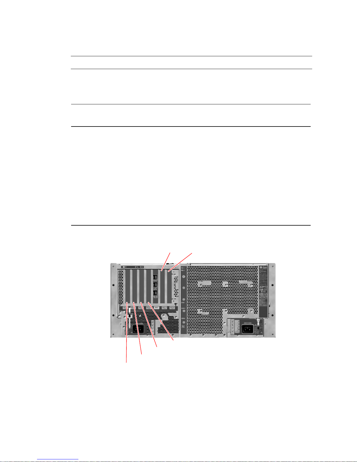
Note – PCI cards in a Sun Fire V480 system are not hot-pluggable.
TABLE 3-2 PCI Bus Characteristics, Associated Bridge Chips, Centerplane Devices,
and PCI Slots
Clock Rate (MHz)/
Bandwidth (bits)/
PCI Bridge PCI Bus
Voltage (V) Integrated Devices PCI Slots
0 PCI A 66 MHz
None Full-length
64 bits
3.3V
0 PCI B 33 MHz
64 bits
IDE controller (interface to the
DVD-ROM drive)
5V
1 PCI C 66 MHz
64 bits
FC-AL controller
Ethernet controller
3.3V
1 PCI D 33 MHz
64 bits
5V
FIGURE 3-2 shows the PCI card slots on the PCI riser board.
Ethernet controller
RIO ASIC (USB and EBus
interfaces)
Slot 0Slot 1
slots 0 and 1
Full-length
slot 2, short
slots 3, 4, 5
None
None
FIGURE 3-2 PCI Slots
36 Sun Fire V480 Server Administration Guide • February 2002
Slot 2
Slot 3
Slot 4
Slot 5
Page 65

Configuration Rules
■ Three slots (0, 1, 2) accept short or long PCI cards, while the other three (3, 4, 5)
support only short cards; that is, cards less than 7.5 inches long.
■ 33 MHz slots accept 5V PCI cards; 66 MHz slots are keyed as 3.3V only cards.
■ All slots accept either 32- or 64-bit PCI cards.
■ All slots comply with PCI Local Bus Specification Revision 2.1.
■ Each slot can supply up to 25 watts of power. The total power used for all six slots
must not exceed 90 watts.
■ Compact PCI (cPCI) cards and SBus cards are not supported.
■ A 33-MHz add-in card plugged into either of the 66-MHz slots will cause that bus
to operate at 33 MHz.
■ You can improve overall system availability by installing redundant network or
storage interfaces on separate PCI buses. For additional information, see “About
Multipathing Software” on page 69.
Note – All internal options (except disk drives and power supplies) must be
installed only by qualified service personnel. For information about installing or
removing PCI cards, see the Sun Fire V480 Server Parts Installation and Removal Guide,
which is included on the Sun Fire V480 Documentation CD.
Chapter 3 Hardware Configuration 37
Page 66
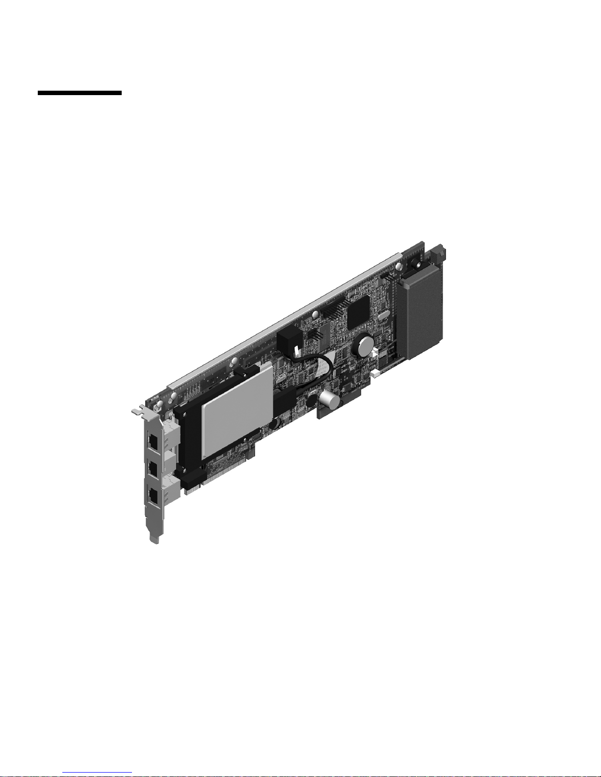
About the Sun Remote System Control
Card
The Sun Remote System Control (RSC) card enables access, monitoring, and control
of the Sun Fire V480 server from a remote location. It is a fully independent
processor card with its own resident firmware, power-on self-test (POST)
diagnostics, and real-time operating system.
FIGURE 3-3 Sun Remote System Control (RSC) Card
The RSC card features modem, serial, and Ethernet interfaces that provide
simultaneous access to the Sun Fire V480 server for multiple RSC software users.
RSC software users are provided secure access to the system’s Solaris and OpenBoot
console functions and have full control over power-on self-test (POST) and
OpenBoot Diagnostics.
38 Sun Fire V480 Server Administration Guide • February 2002
Page 67
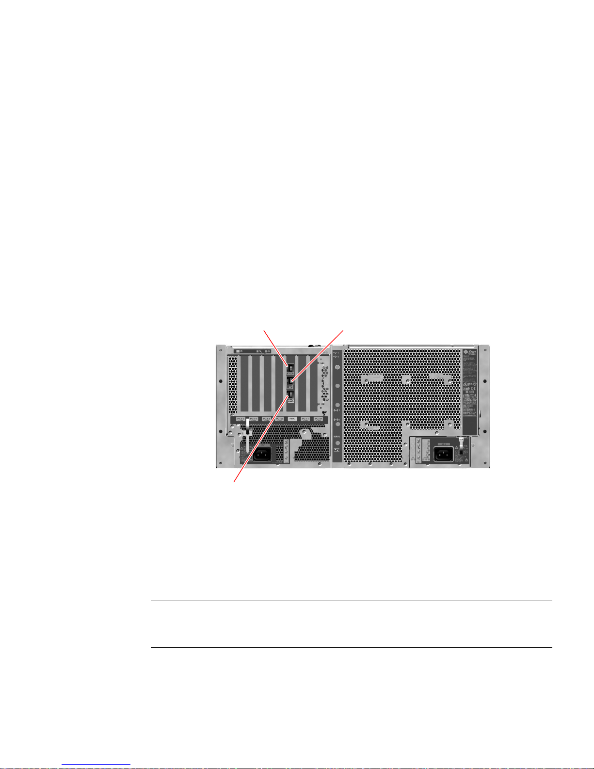
The RSC card runs independently of the host server, and operates off of 5-volt
standby power from the system’s power supplies. It also includes a backup battery
that enables the card to continue operating for up to 30 minutes in the event of a
power failure. The card features on-board devices that interface with the system’s
environmental monitoring subsystem and can automatically alert administrators to
system problems. Together these features enable the RSC card and RSC software to
serve as a “lights out” management tool that continues to function even when the
server operating system goes offline, the system is powered off, or a power outage
occurs.
The RSC card plugs into a dedicated slot on the system PCI riser board and provides
the following ports (listed in order from top to bottom, as shown in
FIGURE 3-4)
through an opening in the system’s back panel:
■ Serial communication port via an RJ-45 connector
■ 56-Kbps modem port via an RJ-11 connector
■ 10-Mbps Ethernet port via an RJ-45 twisted-pair Ethernet (TPE) connector
RSC serial port
RSC modem port
RSC Ethernet port
FIGURE 3-4 RSC Card Ports
All three RSC connection ports can be used simultaneously or individually disabled.
The modem supports regular asynchronous serial protocol, and can also support the
Point-to-Point Protocol (PPP). When running PPP, a standard internet TCP/IP
protocol stack is available over the modem interface.
Note – You must install the Solaris operating environment and the Sun Remote
System Control software prior to setting up an RSC console. For more information,
see “How to Monitor the System Using RSC” on page 195.
Chapter 3 Hardware Configuration 39
Page 68

Once you install the operating environment and the RSC software, you can then
configure the system to use RSC as the system console. For detailed instructions, see
“How to Redirect the System Console to RSC” on page 165.
Configuration Rules
■ The RSC card is installed in a dedicated slot on the system PCI riser board. Never
move the RSC card to another system slot, as it is not a PCI-compatible card.
■ The RSC card is not a hot-pluggable component. Before installing or removing an
RSC card, you must power off the system and disconnect all system power cords.
Note – All internal options (except disk drives and power supplies) must be
installed only by qualified service personnel. For information about installing or
removing the RSC card, see the Sun Fire V480 Server Parts Installation and Removal
Guide, which is included on the Sun Fire V480 Documentation CD.
About Hardware Jumpers
Three jumpers each are located on the Sun Fire V480 system’s PCI riser board and
RSC card. Note that jumpers are set at the factory to ensure best system
performance. Be aware that moving any jumper shunt from its default location can
render the system unstable or unuseable.
All jumpers are marked with identification numbers. For example, the jumpers on
the system PCI riser board are marked J1102, J1103, and J1104. Jumper pins are
located immediately adjacent to the identification number. The default jumper
positions are indicated on the board by a white outline. Pin 1 is marked with an
asterisk (*), as shown in
J 2XXX
*
*
*
FIGURE 3-5 Jumper Identification Guide
FIGURE 3-5.
Jumper number
Pins
Asterisks indicate pin 1
Shaded region indicates
default jumper position
40 Sun Fire V480 Server Administration Guide • February 2002
Page 69
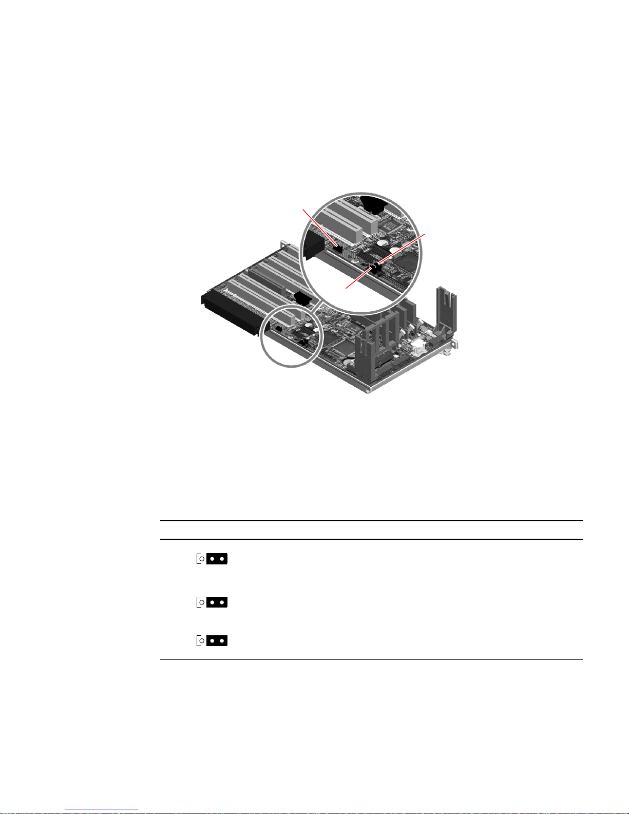
PCI Riser Board Jumpers
On the PCI riser board are three jumpers, two of which affect transactions with the
system boot PROM and one of which is reserved for future use.
the locations of these three jumpers.
J1103
J1104
J1102
FIGURE 3-6 illustrates
FIGURE 3-6 Hardware Jumpers on PCI Riser Board
The functions of the PCI riser board jumpers are shown in TABLE 3-3.
TABLE 3-3 PCI Riser Board Jumper Functions
Jumper Shunt on Pins 1 + 2 Selects Shunt on Pins 2 + 3 Selects Default Setting
J1102
J1103
J1104
321
321
321
OpenBoot flash PROM Optional debug device
populating connector in
position J1101
Reserved for future use Reserved for future use 1 + 2
OpenBoot flash PROM
Write-enabled
OpenBoot flash PROM
Write-protected
1+2
1+2
Each jumper on the PCI riser board has two options, as described in the following
list.
Chapter 3 Hardware Configuration 41
Page 70
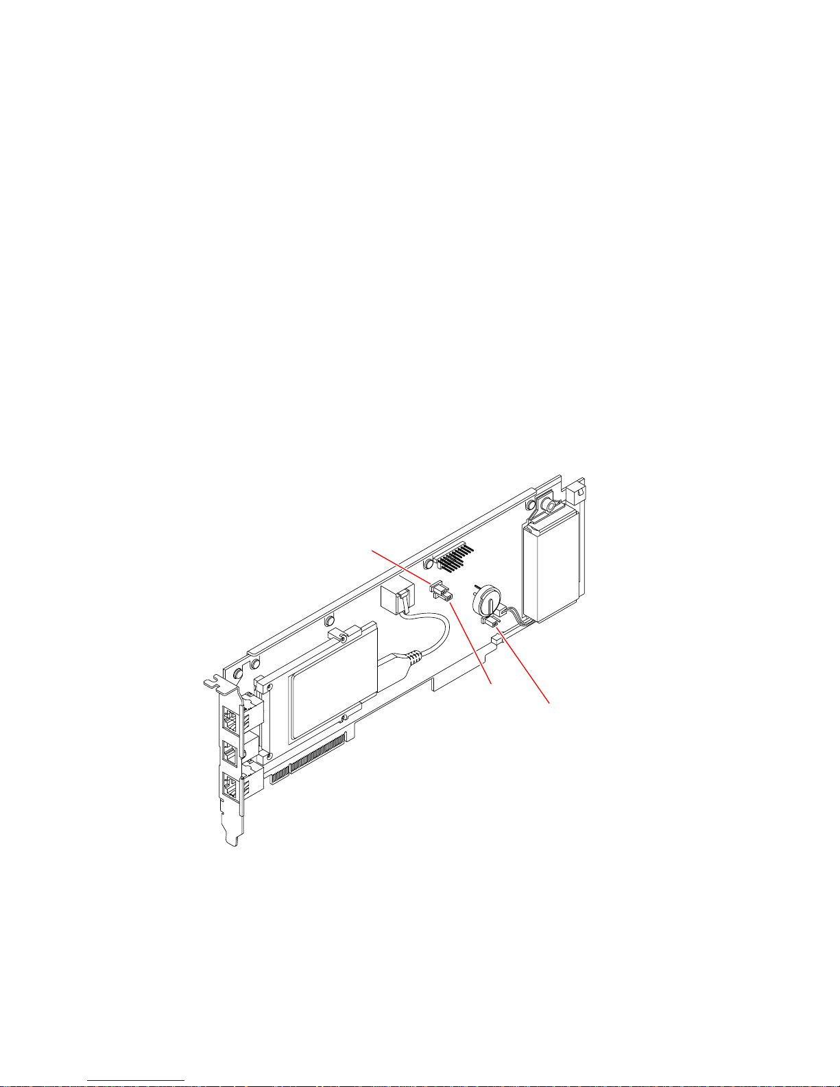
■ J1102 – Labeled “CS” on the PCI riser board, this jumper is used to select the boot
PROM device. In the default position with the shunt covering pins 1 and 2, the
system boots the OpenBoot flash PROM on the centerplane. In the other position,
the system boots by way of an optional debug device that populates the connector
at location J1101.
■ J1103 – Labeled “Hi-Lo” on the PCI riser board, this jumper is reserved for future
use.
■ J1104 – Labeled “WREN” on the PCI riser board, this jumper controls write
permissions for the system boot PROM. In the default position with the shunt
covering pins 1 and 2, the system boot PROM is write-enabled. Moving the shunt
to the other position prevents updating the PROM.
RSC Card Jumpers
The locations of jumpers on the RSC card are shown in FIGURE 3-7.
J0502
FIGURE 3-7 Hardware Jumpers on RSC Card
J0501
J0403
42 Sun Fire V480 Server Administration Guide • February 2002
Page 71

The functions of the RSC card jumpers are shown in TABLE 3-4.
TABLE 3-4 RSC Card Jumper Functions
Jumper Shunt on Pins 1 + 2 Selects Shunt on Pins 2 + 3 Selects Default Setting
J0502
321
J0501
321
J0403
123
Not used Disable mirror 2 + 3
Normal booting Not used 1 + 2
FRU PROM
write-enabled
FRU PROM
write-protected
1+2
Note – Do not change the configuration of J0501 and J0502 from the default settings;
otherwise, the RSC card will not boot.
About the Power Supplies
A central power distribution board (PDB) delivers DC power to all internal system
components. The system’s two standard power supplies—called Power Supply 0
and Power Supply 1—plug in directly to connectors on this board, and all of the
supplies installed share equally in satisfying the power demands of the system. AC
power is brought into the PDB by way of two board-mounted IEC320 receptacles,
each dedicated to one power supply.
Chapter 3 Hardware Configuration 43
Page 72

The Sun Fire V480 system’s power supplies are modular units, designed for fast,
easy installation or removal, even while the system is fully operational. Power
supplies are installed in bays at the front of the system, as shown in the following
figure.
Location of Power Supply 0 Location of Power Supply 1
FIGURE 3-8 Power Supply Locations
The power supplies operate over an AC input range of 100–240 VAC, 50–60 Hz,
without user intervention. The power supplies are capable of providing up to 1184
watts of DC power. The basic system configuration comes with two power supplies
installed, either of which is capable of providing sufficient power for a maximally
configured system.
The power supplies provide 48-volt and 5-volt standby outputs to the system. The
48-volt output powers point-of-load DC/DC converters that provide 1.5V, 1.8V, 2.5V,
3.3V, 5V, and 12V to the system components. Output current is shared equally
between both supplies via active current-sharing circuitry.
Power supplies in a redundant configuration feature a hot-swap capability. You can
remove and replace a faulty power supply without shutting down the operating
system or turning off the system power. For additional details, see “About
Hot-Pluggable and Hot-Swappable Components” on page 30.
Each power supply has separate status LEDs to provide power and fault status
information. For additional details, see “How to Isolate Faults Using LEDs” on
page 176.
44 Sun Fire V480 Server Administration Guide • February 2002
Page 73
Configuration Rule
■ Good practice is to connect each power supply to a separate AC circuit, which
will enable the system to remain operational if one of the AC circuits fails.
Consult your local electrical codes for any additional requirements.
Caution – If any power supply fails, leave the supply in its bay until you are ready
to install a replacement.
For information about installing power supplies, see the Sun Fire V480 Server Parts
Installation and Removal Guide.
About the Fan Trays
The basic system is equipped with five fans mounted on two fan trays, providing
front-to-rear cooling: Fan Tray 0, which holds three fans that cool the CPUs, and Fan
Tray 1, which holds two fans that cool the FC-AL drives and PCI cards. Fan Tray 0 is
accessible from the front of the system, while Fan Tray 1 requires that you remove
the system’s PCI access panel to gain access to it. Power supplies are cooled
separately, each with its own internal fans.
Caution – Fans on a Sun Fire V480 system are not hot-pluggable. Attempting to
replace a fan tray while the system is running poses an extreme risk of bodily injury.
Caution – A complete set of two working fan trays must be present in the system at
all times. After removing a fan tray, you must install a replacement fan tray. Failure
to install a replacement tray could lead to serious overheating of your system and
result in severe damage to the system. For more information, see “Environmental
Monitoring and Control” on page 23 and the Sun Fire V480 Server Parts Installation
and Removal Guide.
Chapter 3 Hardware Configuration 45
Page 74
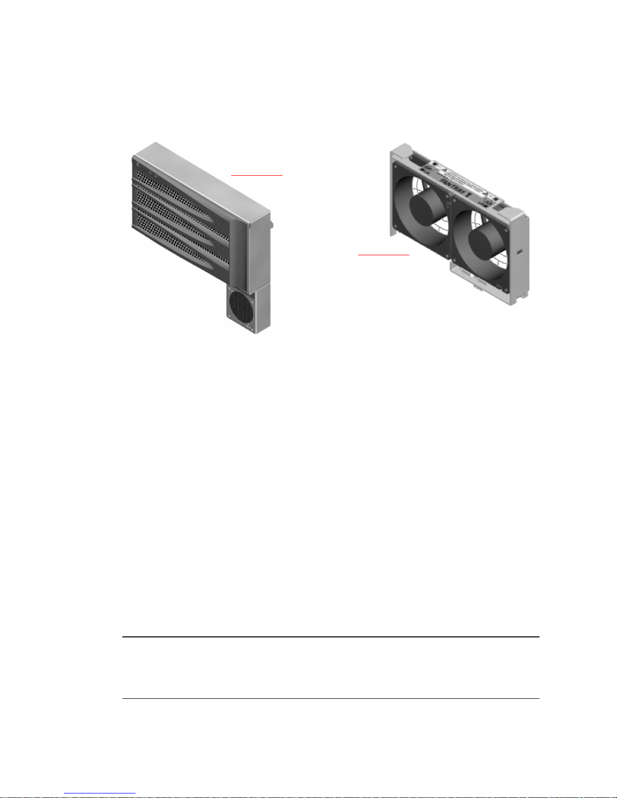
The following figure shows both fan trays. The figure on the left shows Fan Tray 0,
which cools the CPUs. The figure on the right shows Fan Tray 1, which cools the
FC-AL drives and PCI cards.
Fan Tray 0
Fan Tray 1
FIGURE 3-9 Fan Trays
Status for each fan tray is indicated by separate LEDs on the system’s front panel
that are activated by the environmental monitoring subsystem. The fans operate at
full speed all the time—speed is not adjustable. Should a fan speed fall below a
predetermined threshold, the environmental monitoring subsystem prints a warning
and lights the appropriate Fault LED. For additional details, see “How to Isolate
Faults Using LEDs” on page 176.
For each fan in the system, the environmental monitoring subsystem monitors or
controls the following:
■ Fan speed in revolutions per minute (RPM) (monitored)
■ Fan Fault LEDs (controlled)
Configuration Rule
■ The minimum system configuration requires a complete set of two working fan
trays—Fan Tray 0 for the CPUs and Fan Tray 1 for the FC-AL drives and PCI
cards.
Note – All internal options (except disk drives and power supplies) must be
installed only by qualified service personnel. For information about installing or
removing fan tray assemblies, see the Sun Fire V480 Server Parts Installation and
Removal Guide, which is included on the Sun Fire V480 Documentation CD.
46 Sun Fire V480 Server Administration Guide • February 2002
Page 75
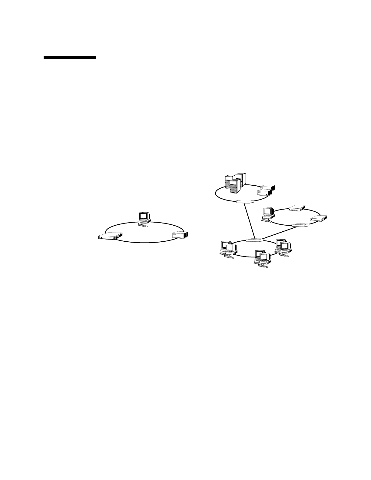
About FC-AL Technology
Fibre Channel (FC) is a high-performance serial interconnect standard designed for
bidirectional, point-to-point communication among servers, storage systems,
workstations, switches, and hubs.
Fibre Channel-Arbitrated Loop (FC-AL) is an important enhancement to the FC
standard, developed specifically to meet the needs of storage system interconnects.
Employing a simple loop topology, FC-AL can support both simple configurations
and complex arrangements of hubs, switches, servers, and storage systems.
FC-AL devices employ a high-performance serial interface, which supports multiple
standard protocols such as Small Computer Systems Interface (SCSI) and
Asynchronous Transfer Mode (ATM). By supporting these standard protocols,
FC-AL preserves any investment in legacy systems, firmware, applications, and
software.
The unique features of FC-AL provide many advantages over other data transfer
technologies. For additional information about FC-AL technology, visit the Fibre
Channel Association Web site at www.fibrechannel.com.
Chapter 3 Hardware Configuration 47
Page 76

The following table lists the features and advantages of FC-AL technology.
TABLE 3-5 FC-AL Features and Advantages
FC-AL Features Advantages
Supports 100-Mbyte per second data transfer
rate (200 Mbytes per second with dual
porting).
Capable of addressing up to 127 devices per
loop (controlled by a single controller)
Provides for reliability, availability, and
serviceability (RAS) features such as
hot-pluggable and dual-ported disks,
redundant data paths, and multiple host
connections.
Supports standard protocols. Migration to FC-AL produces small or no
Implements a simple serial protocol over
copper or fiber cable.
Supports redundant array of independent
disks (RAID).
1. The 127 supported devices include the FC-AL controller required to support each arbitrated loop.
1
.
High throughput meets the demands of current
generation high-performance processors and
disks.
High connectivity controlled by one device
allows flexible and simpler configurations.
RAS features provide improved fault tolerance
and data availability.
impact on software and firmware.
Configurations that use serial connections are
less complex because of the reduced number of
cables per connection.
RAID support enhances data availability.
About the FC-AL Backplane
All Sun Fire V480 servers include a single FC-AL backplane with connections for
two internal hard disks, both of which are hot-pluggable.
The FC-AL backplane accepts two, low-profile (1.0-inch, 2.54-cm), dual-ported
FC-AL disk drives. Each disk drive is connected to the backplane via a standard
40-pin single connector attachment (SCA) interface. Incorporating all power and
signal connections into a single, blind-mating connector, SCA technology makes it
easy to add or remove disk drives from the system. Disks using SCA connectors
provide higher availability and better serviceability than disks using other types of
connectors.
The FC-AL backplane provides dual-loop access to both internal disk drives.
Dual-loop configurations enable each disk drive to be accessed through two separate
and distinct data paths. This capability provides:
48 Sun Fire V480 Server Administration Guide • February 2002
Page 77

■ Increased bandwidth – Allowing faster data transfer rates than those for single-loop
configurations
■ Hardware redundancy – Providing the ability to sustain component failures in one
path by switching all data transfers to an alternate path
Note – To take advantage of the dual-loop capability of the FC-AL backplane, an
optional PCI FC-AL host adapter card must be installed to control the second loop
(Loop B). For more information, see “About the FC-AL Host Adapters” on page 50.
Port bypass controllers (PBCs) on the disk backplane ensure loop integrity. When a
disk or external device is unplugged or fails, the PBCs automatically bypass the
device, closing the loop to maintain data availability.
Configuration Rules
■ The FC-AL backplane requires low-profile (1.0-inch, 2.54-cm) disk drives.
■ The FC-AL disks are hot-pluggable.
For information about installing or removing an FC-AL disk or disk backplane, see
the Sun Fire V480 Server Parts Installation and Removal Guide, which is included on the
Sun Fire V480 Documentation CD.
About the HSSDC FC-AL Port
The Sun Fire V480 system back panel includes an FC-AL port with a high-speed
serial data connector (HSSDC). This connector supports several hard drive data
storage systems.
Note – At this time, no Sun storage products are supported utilizing the HSSDC
connector.
Chapter 3 Hardware Configuration 49
Page 78

About the FC-AL Host Adapters
The Sun Fire V480 server uses an intelligent Fibre Channel processor as its on-board
FC-AL controller. Integrated into the system centerplane, the processor resides on
PCI Bus C and supports a 64-bit, 66-MHz PCI interface. The on-board FC-AL
controller controls FC-AL operations on Loop A.
To take advantage of the dual-loop capability of the FC-AL backplane, an optional
PCI FC-AL host adapter card and optional cable are required to control the second
loop (Loop B). For this purpose, Sun offers the Sun StorEdge PCI Dual Fibre Channel
Host Adapter card. See the Sun Fire V480 Server Parts Installation and Removal Guide,
which is included on the Sun Fire V480 Documentation CD, for installation
instructions.
Configuration Rules
■ The Sun Fire V480 server does not support all FC-AL host adapter cards. Contact
your Sun sales or support engineer for a list of supported cards.
■ For best performance, install 66-MHz FC-AL host adapter cards in a 66-MHz PCI
slot (slot 0 or 1, if available). See “About the PCI Cards and Buses” on page 35.
Note – All internal options (except disk drives and power supplies) must be
installed only by qualified service personnel. For information about installing or
removing a PCI FC-AL host adapter card, see the Sun Fire V480 Server Parts
Installation and Removal Guide, which is included on the Sun Fire V480
Documentation CD.
About the Internal Disk Drives
The Sun Fire V480 system includes two internal, low-profile (1.0-inch, 2.54-cm)
FC-AL disk drives, attached to a backplane. (The system also includes an external
FC-AL port; see the section, “About the HSSDC FC-AL Port” on page 49.) Internal
disks are available in storage capacities of 36 or 73 Gbytes, with a rotation speed of
10,000 RPM. The maximum internal storage capacity is 146 Gbytes (using two
73-Gbyte disks), with larger capacities possible as disk storage capacities continue to
grow.
50 Sun Fire V480 Server Administration Guide • February 2002
Page 79

Sun Fire V480 disk drives are dual-ported for multipath access. When used in a
dual-loop configuration—with the optional addition of a second FC-AL controller on
a PCI adapter card—each drive can be accessed through two separate and distinct
data paths.
Sun Fire V480 disk drives are hot-pluggable. You can add, remove, or replace disks
while the system continues to operate. This capability significantly reduces system
downtime associated with disk drive replacement. Disk drive hot-plug procedures
involve software commands for preparing the system prior to removing a disk drive
and for reconfiguring the operating environment after installing a drive. For detailed
instructions, see the Sun Fire V480 Server Parts Installation and Removal Guide, which
is included on the Sun Fire V480 Documentation CD.
Three LEDs are associated with each drive, indicating the drive’s operating status,
hot-plug readiness, and any fault conditions associated with the drive. These status
LEDs help you quickly to identify drives requiring service. See
LEDs” on page 17,
Drive LEDs” on page 17, for a description of these LEDs.
TABLE 2-2, “Fan Tray LEDs” on page 17, and TABLE 2-3, “Hard Disk
TABLE 2-1, “System
Configuration Rule
■ Disk drives must be Sun standard FC-AL disks with low-profile (1.0-inch,
2.54-cm) form factors.
About the Serial Port
The system provides a serial communication port through an RJ-45 connector
located on the back panel. The port supports baud rates of 50, 75, 110, 200, 300, 600,
1200, 1800, 2400, 4800, 9600, 19200, 38400, 57600, 76800, 115200, 153600, 230400,
307200, and 460800.
The port is accessible by connecting an RJ-45 serial cable to the back panel serial port
connector. For your convenience, a serial port adapter (part number 530-2889-03) is
included in your Sun Fire V480 server ship kit. This adapter enables you to use a
standard RJ-45 serial cable to connect directly from the serial connector on the back
panel to a Sun workstation, or to any other terminal that is equipped with a DB-25
serial connector.
For the serial port location, see “Locating Back Panel Features” on page 20. Also see
Appendix A, “Connector Pinouts” on page 213.
Chapter 3 Hardware Configuration 51
Page 80

About the USB Ports
The system’s back panel provides two external Universal Serial Bus (USB) ports for
connection to USB peripheral devices such as:
■ Sun Type-6 USB keyboard
■ Sun opto-mechanical three-button USB mouse
■ Modems
■ Printers
■ Scanners
■ Digital cameras
For USB port locations, see “Locating Back Panel Features” on page 20.
The USB ports are compliant with the Open Host Controller Interface (Open HCI)
specification for USB Revision 1.0. Both ports support isochronous and
asynchronous modes. The ports enable data transmission at speeds of 1.5 Mbps and
12 Mbps. Note that the USB data transmission speed is significantly faster than that
of the standard serial ports, which operate at a maximum rate of 460.8 Kbaud.
The USB ports are accessible by connecting a USB cable to either back panel USB
connector. The connectors at each end of a USB cable are different, so you cannot
connect them incorrectly. One connector plugs in to the system or USB hub; the other
plugs in to the peripheral device. Up to 126 USB devices can be connected to the bus
simultaneously, through the use of USB hubs. The Universal Serial Bus provides
power for smaller USB devices such as modems. Larger USB devices, such as
scanners, require their own power source.
Both USB ports support hot-plugging. You can connect and disconnect the USB cable
and peripheral devices while the system is running, without affecting system
operations. However, you can only perform USB hot-plug operations while the
operating system is running. USB hot-plug operations are not supported when the
system ok prompt is displayed.
52 Sun Fire V480 Server Administration Guide • February 2002
Page 81

CHAPTER
4
Network Interfaces and System
Firmware
This chapter describes the networking options of the system and provides
background information about the system’s firmware.
Information covered in this chapter includes:
■ “About the Network Interfaces” on page 54
■ “About Redundant Network Interfaces” on page 55
■ “About the ok Prompt” on page 55
■ “About OpenBoot Environmental Monitoring” on page 58
■ “About OpenBoot Emergency Procedures” on page 60
■ “About Automatic System Recovery” on page 63
53
Page 82

About the Network Interfaces
The Sun Fire V480 server provides two on-board Ethernet interfaces, which reside on
the system centerplane and conform to the IEEE 802.3z Ethernet standard. For an
illustration of the Ethernet ports, see
page 21. The Ethernet interfaces operate at 10 Mbps, 100 Mbps, and 1000 Mbps.
Two back panel ports with RJ-45 connectors provide access to the on-board Ethernet
interfaces. Each interface is configured with a unique media access control (MAC)
address. Each connector features two LEDs, as described in
TABLE 4-1 Ethernet Port LEDs
Name Description
Activity This amber LED lights to indicate that data is either being
transmitted or received by the particular port.
Link Up This green LED lights when a link is established at the particular
port with its link partner.
Additional Ethernet interfaces or connections to other network types are available
by installing the appropriate PCI interface cards. An additional network interface
card can serve as a redundant network interface for one of the system’s on-board
interfaces. If the active network interface becomes unavailable, the system can
automatically switch to the redundant interface to maintain availability. This
capability is known as automatic failover and must be configured at the Solaris
operating environment level. For additional details, see “About Redundant Network
Interfaces” on page 55.
FIGURE 2-4, “Back Panel External Ports” on
TABLE 4-1.
The Ethernet driver is installed automatically during the Solaris installation
procedure.
For instructions on configuring the system network interfaces, see:
■ “How to Configure the Primary Network Interface” on page 150
■ “How to Configure Additional Network Interfaces” on page 152
54 Sun Fire V480 Server Administration Guide • February 2002
Page 83

About Redundant Network Interfaces
You can configure your system with redundant network interfaces to provide a
highly available network connection. Such a configuration relies on special Solaris
software features to detect a failed or failing network interface and automatically
switch all network traffic over to the redundant interface. This capability is known
as automatic failover.
To set up redundant network interfaces, you can enable automatic failover between
the two similar interfaces using the IP Network Multipathing feature of the Solaris
operating environment. For additional details, see “About Multipathing Software”
on page 69. You can also install a pair of identical PCI network interface cards, or
add a single card that provides an interface identical to one of the two on-board
Ethernet interfaces.
To help maximize system availability, make sure that any redundant network
interfaces reside on separate PCI buses, supported by separate PCI bridges. For
additional details, see “About the PCI Cards and Buses” on page 35.
About the ok Prompt
A Sun Fire V480 system with Solaris operating environment software is capable of
operating at different run levels. A synopsis of run levels follows; for a full
description, see the Solaris system administration documentation.
Most of the time, you operate a Sun Fire V480 system at run level 2, or run level 3,
which are multiuser states with access to full system and network resources.
Occasionally, you may operate the system at run level 1, which is a single-user
administrative state. However, the most basic state is run level 0. At this state, it is
safe to turn off power to the system.
When a Sun Fire V480 system is at run level 0, the ok prompt appears. This prompt
indicates that the OpenBoot firmware is in control of the system.
There are a number of scenarios in which this can happen.
■ The system comes up under OpenBoot firmware control before the operating
environment software is installed, or whenever the auto-boot? OpenBoot
configuration variable is set to false.
■ The system transitions to run level 0 in an orderly way when the operating
environment software is halted.
Chapter 4 Network Interfaces and System Firmware 55
Page 84

■ The system reverts to OpenBoot firmware control when the operating
environment software crashes.
■ During the boot process, there is a serious hardware problem that prevents the
operating environment software from running, and the system reverts to
OpenBoot firmware control.
■ A serious hardware problem develops while the system is running, and the
operating environment software transitions smoothly to run level 0.
■ You deliberately place the Sun Fire V480 system under firmware control in order
to execute firmware-based commands or run diagnostic tests.
It is the last of these scenarios that most often concerns you as an administrator,
since there will be times when you need to reach the ok prompt. The several ways to
do this are outlined in “Ways of Reaching the ok Prompt” on page 57. For detailed
instructions, see “How to Get to the ok Prompt” on page 132.
What You Should Know About Accessing the ok
Prompt
It is important to understand that when you access the ok prompt from a
functioning Sun Fire V480 system, you are suspending the operating environment
software and placing the system under firmware control. Any processes that were
running under the operating environment software are also suspended, and the state
of such software may not be recoverable.
The firmware-based tests and commands you run from the ok prompt have the
potential to affect the state of the system. This means that it is not always possible to
resume execution of the operating environment software from the point at which it
was suspended. Although the go command will resume execution in most
circumstances, in general, each time you drop the system down to the ok prompt,
you should expect to have to reboot it to get back to the operating environment.
As a rule, before suspending the operating environment, you should back up files,
warn users of the impending shutdown, and halt the system in an orderly manner.
However, it is not always possible to take such precautions, especially if the system
is malfunctioning.
56 Sun Fire V480 Server Administration Guide • February 2002
Page 85

Ways of Reaching the ok Prompt
There are several ways to get to the ok prompt, depending on the state of the system
and the means by which you are accessing the system console. In order of
desirability, these are:
■ Graceful halt
■ L1-a or Break key sequence
■ Externally Initiated Reset (XIR)
■ Manual system reset
A discussion of each method follows. For instructions, see “How to Get to the ok
Prompt” on page 132.
Graceful Halt
The preferred method of reaching the ok prompt is to halt the operating
environment software by issuing an appropriate command (for example, the
shutdown, init, halt,oruadmin command) as described in Solaris system
administration documentation.
Gracefully halting the system prevents data loss, allows you to warn users
beforehand, and causes minimal disruption. You can usually perform a graceful halt,
provided Solaris operating environment software is running and the hardware has
not experienced serious failure.
L1-A or Break Key Sequence
When it is impossible or impractical to halt the system gracefully, you can get to the
ok prompt by typing the L1-A (or Stop-A) key sequence from a Sun keyboard, or, if
you have an alphanumeric terminal attached to the Sun Fire V480 system, by
pressing the Break key.
If you use this method to reach the ok prompt, be aware that issuing certain
OpenBoot commands (like probe-scsi, probe-scsi-all, and probe-ide) may
hang the system.
Externally Initiated Reset (XIR)
Generating an externally initiated reset (XIR) has the advantage of allowing you to
issue the sync command to preserve file systems and produce a dump file of part of
the system state for diagnostic purposes. Forcing an XIR may be effective in breaking
Chapter 4 Network Interfaces and System Firmware 57
Page 86
the deadlock that is hanging up the system, but it also precludes the orderly
shutdown of applications, and so is not the preferred method of reaching the ok
prompt.
Manual System Reset
Reaching the ok prompt by performing a manual system reset should be the method
of last resort. Doing this results in the loss of all system coherence and state
information. In particular, it resets all OpenBoot configuration variables to their
default values, so if you have edited these variables, your changes will be lost. It also
corrupts the machine’s file systems, although the fsck command usually restores
them. Use this method only if nothing else works.
Caution – Forcing a manual system reset results in loss of system state data.
For More Information
For more information about the OpenBoot firmware, see:
■ OpenBoot 4.x Command Reference Manual
An online version of the manual is included with the OpenBoot Collection
AnswerBook that ships with Solaris software.
About OpenBoot Environmental
Monitoring
Environmental monitoring and control capabilities for Sun Fire V480 systems reside
at both the operating system level and the OpenBoot firmware level. This ensures
that monitoring capabilities are operational even if the system has halted or is
unable to boot. Whenever the system is under OpenBoot control, the OpenBoot
environmental monitor checks the state of the system power supplies, fans, and
temperature sensors periodically. If it detects any voltage, current, fan speed, or
temperature irregularities, the monitor generates a warning message to the system
console.
For additional information about the system’s environmental monitoring
capabilities, see “Environmental Monitoring and Control” on page 23.
58 Sun Fire V480 Server Administration Guide • February 2002
Page 87

Enabling or Disabling the OpenBoot
Environmental Monitor
The OpenBoot environmental monitor is enabled by default whenever the system is
operating at the ok prompt. However, you can enable or disable it yourself using the
OpenBoot commands env-on and env-off. For more information, see:
■ “How to Enable OpenBoot Environmental Monitoring” on page 160
■ “How to Disable OpenBoot Environmental Monitoring” on page 160
Note – Using the Stop-A keyboard command to enter the OpenBoot environment
during power-on or reset will immediately disable the OpenBoot environmental
monitor. If you want the OpenBoot PROM environmental monitor enabled, you
must reenable it prior to rebooting the system. If you enter the OpenBoot
environment through any other means—by halting the operating system, by
power-cycling the system, or as a result of a system panic—the OpenBoot
environmental monitor will remain enabled.
Automatic System Shutdown
If the OpenBoot environmental monitor detects a critical overtemperature condition,
it will initiate an automatic system shutdown sequence. In this case, a warning
similar to the following is generated to the system console:
WARNING: SYSTEM POWERING DOWN IN 30 SECONDS!
Press Ctrl-C to cancel shutdown sequence and return to ok prompt.
If necessary, you can type Ctrl-C to abort the automatic shutdown and return to the
system ok prompt; otherwise, after the 30 seconds expire, the system will power off
automatically.
Note – Typing Ctrl-C to abort an impending shutdown also has the effect of
disabling the OpenBoot environmental monitor. This gives you enough time to
replace the component responsible for the critical condition without triggering
another automatic shutdown sequence. After replacing the faulty component, you
must type the env-on command to reinstate OpenBoot environmental monitoring.
Chapter 4 Network Interfaces and System Firmware 59
Page 88
Caution – If you type Ctrl-C to abort an impending shutdown, you should
immediately replace the component responsible for the critical condition. If a
replacement part is not immediately available, power off the system to avoid
damaging system hardware.
OpenBoot Environmental Status Information
The OpenBoot command .env enables you to obtain status on the current state of
everything of interest to the OpenBoot environmental monitor. You can obtain
environmental status at any time, regardless of whether OpenBoot environmental
monitoring is enabled or disabled. The .env status command simply reports the
current environmental status information; it does not take action if anything is
abnormal or out of range.
For an example of .env command output, see “How to Obtain OpenBoot
Environmental Status Information” on page 161.
About OpenBoot Emergency Procedures
The introduction of Universal Serial Bus (USB) keyboards with the newest Sun
systems has made it necessary to change some of the OpenBoot emergency
procedures. Specifically, the Stop-N, Stop-D, and Stop-F commands that were
available on systems with non-USB keyboards are not supported on systems that use
USB keyboards, such as the Sun Fire V480 system. The following sections describe
the OpenBoot emergency procedures for systems with non-USB keyboards and for
newer systems with USB keyboards.
60 Sun Fire V480 Server Administration Guide • February 2002
Page 89

OpenBoot Emergency Procedures for Systems
With Non-USB Keyboards
The following table summarizes the Stop key command functions for systems that
use standard (non-USB) keyboards.
TABLE 4-2 Stop Key Command Functions for Systems With Standard Keyboards
Command Description
Stop Bypass POST. This command does not depend on security mode.
(Note: Some systems bypass POST as a default. In such cases, use
Stop-D to start POST.)
Stop-A Abort.
Stop-D Enter the diagnostic mode (set diag-switch? to true).
Stop-F Enter Forth on TTYA instead of probing. Use fexit to continue
with the initialization sequence. Useful if hardware is broken.
Stop-N Reset OpenBoot configuration variables to their default values.
OpenBoot Emergency Procedures for Systems
With USB Keyboards
The following paragraphs describe how to perform the functions of the Stop
commands on systems that use USB keyboards, such as the Sun Fire V480 system.
These same functions are available through Sun Remote System Control (RSC).
Stop-A Functionality
Stop-A (Abort) key sequence works the same as it does on systems with standard
keyboards, except that it does not work during the first few seconds after the
machine is reset.
Stop-N Functionality
1. After turning on the power to your system, wait until the system Fault LED on the
front panel begins to blink.
Chapter 4 Network Interfaces and System Firmware 61
Page 90

2. Press the front panel Power button twice (with a short, one-second delay in
between presses).
A screen similar to the following is displayed to indicate that you have successfully
reset the OpenBoot configuration variables (see “Stage One: OpenBoot Firmware
and POST” on page 84 for more information about IDPROM) to the default values.
(Note that “NVRAM” in the output is synonymous with IDPROM.)
Sun Fire V480 (4 X UltraSPARC-III cu 900 MHz), Keyboard Present
OpenBoot x.x, 256 MB memory installed, Serial #xxxxxxxx.
Ethernet address xx:xx:xx:xx:xx:xx, Host ID: xxxxxxxx.
Safe NVRAM mode, the following NVRAM configuration variables have
been overridden:
‘diag-switch?’ is true
‘use-nvramrc?’ is false
‘input-device’, ‘output-device’ are defaulted
‘ttya-mode’is defaulted
These changes are temporary and the original values will be
restored after the next hardware or software reset.
ok
Note that some OpenBoot configuration variables are reset to their defaults. They
include variables that are more likely to cause problems, such as ttya settings.
These IDPROM settings are only reset to the defaults for this power cycle. If you do
nothing other than reset the system at this point, the values are not permanently
changed. Only settings that you change manually at this point become permanent.
All other customized IDPROM settings are retained.
Typing set-defaults discards any customized IDPROM values and restores the
default settings for all OpenBoot configuration variables.
Note – Once the front panel LEDs stop blinking and the Power/OK LED stays lit,
pressing the Power button again will begin a graceful shutdown of the system.
Stop-F Functionality
The Stop-F functionality is not available on systems with USB keyboards.
62 Sun Fire V480 Server Administration Guide • February 2002
Page 91

Stop-D Functionality
The Stop-D (Diags) key sequence is not supported on systems with USB keyboards.
However, the Stop-D functionality can be closely emulated by turning the system
control switch to the Diagnostics position. For more information, see “System
Control Switch” on page 18.
About Automatic System Recovery
The system provides for automatic system recovery (ASR) from the following types
of hardware component failures:
■ CPUs
■ Memory modules
■ PCI buses and cards
■ FC-AL subsystem
■ Ethernet interface
■ USB interface
■ Serial interface
Automatic system recovery functionality enables the system to resume operation
after experiencing certain non-fatal hardware faults or failures. When ASR is
enabled, the system’s firmware diagnostics automatically detect failed hardware
components, while an auto-configuring capability designed into the OpenBoot
firmware enables the system to unconfigure failed components and restore system
operation. As long as the system is capable of operating without the failed
component, the ASR features enable the system to reboot automatically, without
operator intervention.
During the power-on sequence, if a faulty component is detected, the component is
automatically unconfigured and, if the system remains capable of functioning
without it, the boot sequence continues. In a running system, certain types of failures
(such as a processor failure) can bring the system down. If this happens, the ASR
functionality enables the system to reboot immediately if it is possible for the system
to function without the failed component. This prevents a faulty hardware
component from keeping the entire system down or causing the system to crash
repeatedly.
To support such a degraded boot capability, the OpenBoot firmware uses the 1275
Client Interface (via the device tree) to “mark” a device as either failed or disabled,by
creating an appropriate “status” property in the corresponding device tree node. By
convention, the Solaris operating environment will not activate a driver for any
subsystem so marked. Thus, as long as the failed component is electrically dormant
(that is, it will not cause random bus errors or signal noise, for example), the system
can be rebooted automatically and resume operation while a service call is made.
Chapter 4 Network Interfaces and System Firmware 63
Page 92

Note – ASR is not activated until you enable it. See “How to Enable ASR” on
page 163.
Auto-Boot Options
The OpenBoot firmware provides an IDPROM-stored setting called auto-boot?,
which controls whether the firmware will automatically boot the operating system
after each reset. The default setting for Sun platforms is true.
Normally, if a system fails power-on diagnostics, then auto-boot? is ignored and
the system does not boot unless an operator boots the system manually. This
behavior is obviously not acceptable for a degraded boot scenario. Therefore, the
Sun Fire V480 OpenBoot firmware provides a second setting,
auto-boot-on-error?. This setting controls whether the system will attempt a
degraded boot when a subsystem failure is detected. Both the auto-boot? and
auto-boot-on-error? switches must be set to true to enable an automatic
degraded boot. To set the switches, type:
ok setenv auto-boot? true
ok setenv auto-boot-on-error? true
Note – The default setting for auto-boot-on-error? is false. Therefore, the
system will not attempt a degraded boot unless you change this setting to true.In
addition, the system will not attempt a degraded boot in response to any fatal
non-recoverable error, even if degraded booting is enabled. For examples of fatal
non-recoverable errors, see “Error Handling Summary” on page 64.
Error Handling Summary
Error handling during the power-on sequence falls into one of the following three
cases:
■ If no errors are detected by POST or OpenBoot Diagnostics, the system attempts
to boot if auto-boot? is true.
64 Sun Fire V480 Server Administration Guide • February 2002
Page 93

■ If only non-fatal errors are detected by POST or OpenBoot Diagnostics, the
system attempts to boot if auto-boot? is true and auto-boot-on-error? is
true. Non-fatal errors include the following:
■ FC-AL subsystem failure – In this case, a working alternate path to the boot
disk is required. For more information, see “About Multipathing Software” on
page 69.
■ Ethernet interface failure
■ USB interface failure
■ Serial interface failure
■ PCI card failure
■ CPU failure – In this case, a single CPU failure causes the entire CPU/Memory
board to be unconfigured. Another non-failing CPU/Memory board must be
present in the system for the system to attempt a degraded boot.
■ Memory failure – Given a failed memory module, the firmware will
unconfigure the entire logical bank associated with the failed module. Another
non-failing logical bank must be present in the system for the system to
attempt a degraded boot.
Note – If POST or OpenBoot Diagnostics detects a non-fatal error associated with
the normal boot device, the OpenBoot firmware automatically unconfigures the
failed device and tries the next-in-line boot device, as specified by the boot-device
configuration variable.
■ If a fatal error is detected by POST or OpenBoot Diagnostics, the system will not
boot regardless of the settings of auto-boot? or auto-boot-on-error?. Fatal
non-recoverable errors include the following:
■ All CPUs failed
■ All logical memory banks failed
■ Flash RAM cyclical redundancy check (CRC) failure
■ Critical field-replaceable unit (FRU) PROM configuration data failure
■ Critical application-specific integrated circuit (ASIC) failure
Reset Scenarios
Three OpenBoot configuration variables, diag-switch?, obdiag-trigger, and
post-trigger, control whether the system runs firmware diagnostics in response
to system reset events.
Chapter 4 Network Interfaces and System Firmware 65
Page 94

The standard system reset protocol bypasses POST and OpenBoot Diagnostics
completely unless the variable diag-switch? is set to true. The default setting for
this variable is false. Therefore, to enable ASR, which relies on firmware
diagnostics to detect faulty devices, you must change this setting to true. For
instructions, see “How to Enable ASR” on page 163.
To control which reset events, if any, automatically initiate firmware diagnostics, the
OpenBoot firmware provides variables called obdiag-trigger and
post-trigger. For detailed explanations of these variables and their uses, see
“Controlling POST Diagnostics” on page 88 and “Controlling OpenBoot Diagnostics
Tests” on page 91.
ASR User Commands
The OpenBoot commands .asr, asr-disable, and asr-enable are available for
obtaining ASR status information and for manually unconfiguring or reconfiguring
system devices. For more information, see:
■ “How to Unconfigure a Device Manually” on page 168
■ “How to Reconfigure a Device Manually” on page 170
■ “How to Obtain ASR Status Information” on page 164
66 Sun Fire V480 Server Administration Guide • February 2002
Page 95

CHAPTER
5
System Administration Software
This chapter provides an introduction to system administration software tools
supported on the Sun Fire V480 system.
The following information is covered in this chapter:
■ “About System Administration Software” beginning on page 68
■ “About Multipathing Software” beginning on page 69
■ “About Volume Management Software” beginning on page 70
■ “About Sun Cluster Software” beginning on page 74
■ “About Communicating With the System” beginning on page 75
67
Page 96

About System Administration Software
A number of software-based administration tools are available to help you configure
your system for performance and availability, monitor and manage your system, and
identify hardware problems. These administration tools include:
■ Multipathing software
■ Volume management software
■ Sun Cluster software
The following table provides a summary of each tool with a pointer to additional
information.
TABLE 5-1 System Administration Tool Summary
For More
Tool Description
Information
Multipathing
software
Volume
management
software
Sun Cluster
software
Multipathing software is used to define and control
alternate (redundant) physical paths to I/O devices.
If the active path to a device becomes unavailable,
the software can automatically switch to an alternate
path to maintain availability.
Volume management applications, such as Solstice
DiskSuite and VERITAS Volume Manager, provide
easy-to-use online disk storage management for
enterprise computing environments. Using advanced
RAID technology, these products ensure high data
availability, excellent I/O performance, and
simplified administration.
Sun Cluster software enables you to interconnect
multiple Sun servers so that they work together as a
single, highly available and scalable system. Sun
Cluster software delivers high availability—through
automatic fault detection and recovery—and
scalability, ensuring that mission-critical applications
and services are always available when needed.
See page 69.
See page 70.
See page 74.
68 Sun Fire V480 Server Administration Guide • February 2002
Page 97

About Multipathing Software
Multipathing software lets you define and control redundant physical paths to I/O
devices, such as storage devices and network interfaces. If the active path to a device
becomes unavailable, the software can automatically switch to an alternate path to
maintain availability. This capability is known as automatic failover. To take
advantage of multipathing capabilities, you must configure the server with
redundant hardware, such as redundant network interfaces or two FC-AL host bus
adapters connected to the same dual-ported storage array.
For Sun Fire V480 systems, three different types of multipathing software are
available:
■ Solaris IP Network Multipathing software provides multipathing and load
balancing capabilities for IP network interfaces.
■ VERITAS Volume Manager software includes a feature called Dynamic
Multipathing (DMP), which provides disk multipathing as well as disk load
balancing to optimize I/O throughput.
■ Multiplexed I/O (MPxIO) is a new architecture fully integrated within the Solaris
operating environment (beginning with Solaris 8) that enables I/O devices to be
accessed through multiple host controller interfaces from a single instance of the
I/O device.
For More Information
For information about setting up redundant hardware interfaces for storage devices
or networks, see “About Redundant Network Interfaces” beginning on page 55.
For instructions on how to configure and administer Solaris IP Network
Multipathing, consult the IP Network Multipathing Administration Guide provided
with your specific Solaris release.
For information about VERITAS Volume Manager and its DMP feature, see “About
Volume Management Software” beginning on page 70 and refer to the
documentation provided with the VERITAS Volume Manager software.
For information about MPxIO, see “Multiplexed I/O (MPxIO)” beginning on
page 71 and refer to your Solaris operating environment documentation.
Chapter 5 System Administration Software 69
Page 98

About Volume Management Software
Sun Microsystems offers two different volume management applications for use on
Sun Fire V480 systems:
■ VERITAS Volume Manager software
■ Solstice DiskSuite software
Volume management software lets you create disk volumes. Volumes are logical disk
devices comprising one or more physical disks or partitions from several different
disks. Once you create a volume, the operating system uses and maintains the
volume as if it were a single disk. By providing this logical volume management
layer, the software overcomes the restrictions imposed by physical disk devices.
Sun’s volume management products also provide RAID data redundancy and
performance features. RAID, which stands for redundant array of independent disks,is
a technology that helps protect against disk and hardware failures. Through RAID
technology, volume management software is able to provide high data availability
excellent I/O performance, and simplified administration.
Sun’s volume management applications offer the following features:
■ Support for several types of RAID configurations, which provide varying degrees
of availability, capacity, and performance
■ Hot-spare facilities, which provide for automatic data recovery when disks fail
,
■ Performance analysis tools, which enable you to monitor I/O performance and
isolate bottlenecks
■ A graphical user interface (GUI), which simplifies storage management
■ Support for online resizing, which enables volumes and their file systems to grow
and shrink online
■ Online reconfiguration facilities, which let you change to a different RAID
configuration or modify characteristics of an existing configuration
VERITAS Dynamic Multipathing
VERITAS Volume Manager software actively supports multiported disk arrays. It
automatically recognizes multiple I/O paths to a particular disk device within an
array. Called Dynamic Multipathing (DMP), this capability provides increased
reliability by providing a path failover mechanism. If one connection to a disk is lost,
VERITAS Volume Manager continues to access the data over the remaining
70 Sun Fire V480 Server Administration Guide • February 2002
Page 99

connections. This multipathing capability also provides greater I/O throughput by
automatically balancing the I/O load uniformly across multiple I/O paths to each
disk device.
Multiplexed I/O (MPxIO)
A newer alternative to DMP that is also supported by the Sun Fire V480 server is
multiplexed I/O (MPxIO). Beginning with Solaris 8, MPxIO is fully integrated
within the Solaris operating environment’s core I/O framework. MPxIO enables you
more effectively to represent and manage devices that are accessible through
multiple I/O controller interfaces within a single instance of the Solaris operating
environment.
The MPxIO architecture:
■ Helps protect against I/O outages due to I/O controller failures. Should one I/O
controller fail, MPxIO automatically switches to an alternate controller.
■ Increases I/O performance by load balancing across multiple I/O channels.
Both Sun StorEdge T3 and Sun StorEdge A5x00 storage arrays are supported by
MPxIO on a Sun Fire V480 server. Supported I/O controllers are usoc/fp FC-AL
disk controllers and qlc/fp FC-AL disk controllers.
RAID Concepts
VERITAS Volume Manager and Solstice DiskSuite software support RAID
technology to optimize performance, availability, and user cost. RAID technology
improves performance, reduces recovery time in the event of file system errors, and
increases data availability even in the event of a disk failure. There are several levels
of RAID configurations that provide varying degrees of data availability with
corresponding trade-offs in performance and cost.
This section describes some of the most popular and useful of those configurations,
including:
■ Disk concatenation
■ Disk mirroring (RAID 1)
■ Disk striping (RAID 0)
■ Disk striping with parity (RAID 5)
■ Hot spares
Chapter 5 System Administration Software 71
Page 100
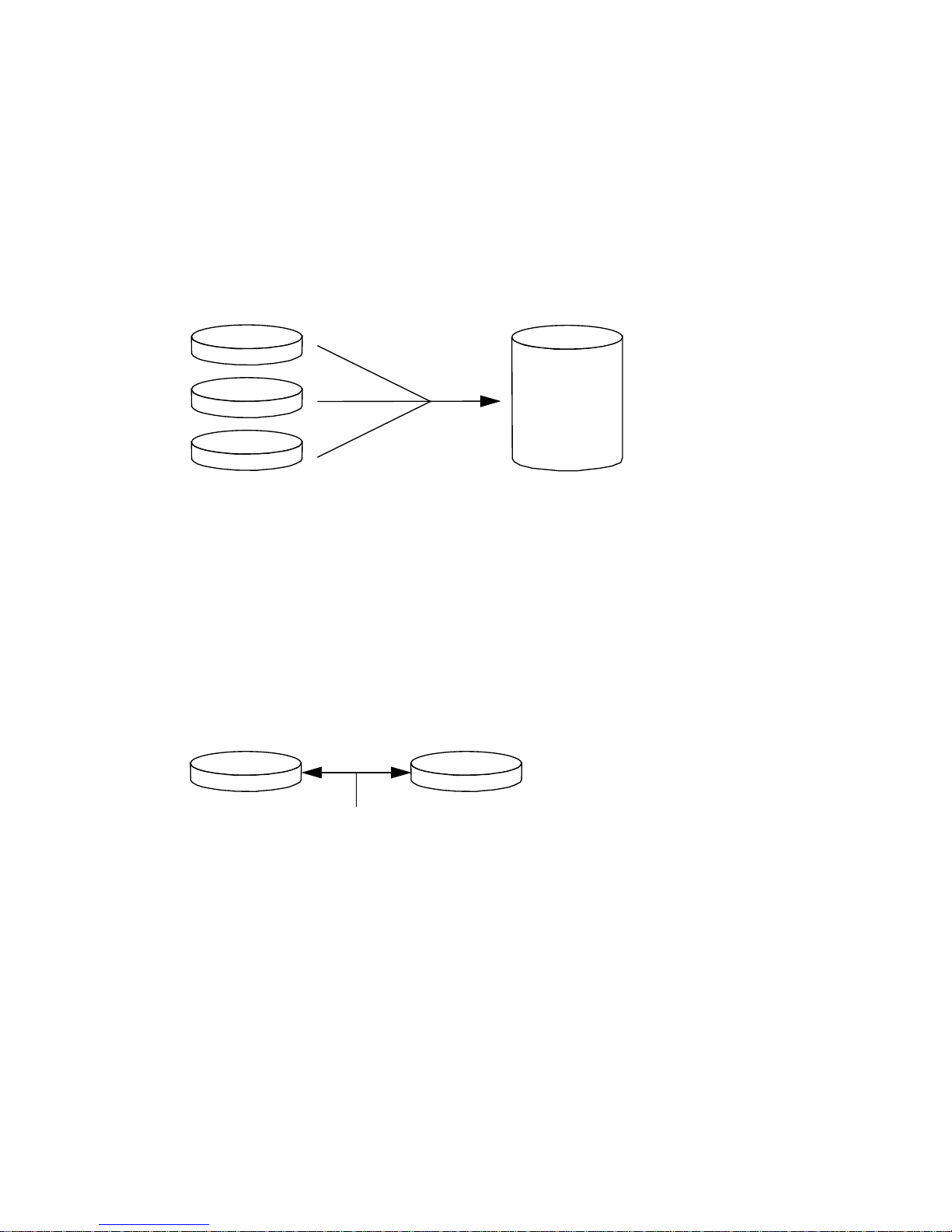
Disk Concatenation
Disk concatenation is a method for increasing logical volume size beyond the
capacity of one disk drive by creating one large volume from two or more smaller
drives. This lets you create arbitrarily large partitions.
Using this method, the concatenated disks are filled with data sequentially, with the
second disk being written to when no space remains on the first, the third when no
room remains on the second, and so on.
RAID 1: Disk Mirroring
Disk mirroring (RAID 1) is a technique that uses data redundancy—two complete
copies of all data stored on two separate disks—to protect against loss of data due to
disk failure. One logical volume is duplicated on two separate disks.
Whenever the operating system needs to write to a mirrored volume, both disks are
updated. The disks are maintained at all times with exactly the same information.
When the operating system needs to read from the mirrored volume, it reads from
whichever disk is more readily accessible at the moment, which can result in
enhanced performance for read operations.
RAID 1 offers the highest level of data protection, but storage costs are high, and
write performance is reduced since all data must be stored twice.
72 Sun Fire V480 Server Administration Guide • February 2002
 Loading...