

Page 1

Sun Fire
™
V215 and V245 Servers
Administration Guide
Sun Microsystems, Inc.
www.sun.com
Part No. 819-3036-10
September 2006, A
Submit comments about this document at: http://www.sun.com/hwdocs/feedback
Page 2

Copyright 2006Sun Microsystems,Inc., 4150 Network Circle, SantaClara, California95054, U.S.A. Allrights reserved.
Sun Microsystems, Inc.has intellectual property rights relating to technologythat isdescribed in thisdocument. Inparticular, and without
limitation, theseintellectual propertyrights may include one ormore ofthe U.S. patentslisted athttp://www.sun.com/patentsand one or
more additional patents orpending patent applications in theU.S. and in other countries.
This documentand the product to which it pertainsare distributedunder licenses restricting theiruse, copying,distribution, and
decompilation. Nopart of the product or of thisdocument may be reproduced in any formby any means without priorwritten authorizationof
Sun andits licensors, if any.
Third-party software, including fonttechnology, iscopyrighted andlicensed from Sun suppliers.
Parts ofthe productmay be derived from BerkeleyBSD systems,licensed from the University ofCalifornia. UNIX is a registered trademark in
the U.S.and in other countries, exclusivelylicensed throughX/Open Company,Ltd.
Sun, SunMicrosystems, theSun logo, Sun Fire, SunVTS,Sun EnterpriseAdministration Mechanism, StorEdge,OpenBoot, docs.sun.com,and
Solaris are trademarksor registeredtrademarks ofSun Microsystems, Inc. in theU.S. and in other countries.
All SPARCtrademarks areused under license and are trademarksor registeredtrademarks ofSPARCInternational, Inc. in the U.S.and in other
countries. Products bearingSPARCtrademarks arebased upon an architecture developed by SunMicrosystems, Inc.
The OPENLOOK and Sun™ Graphical UserInterface was developed by SunMicrosystems, Inc.for its users and licensees.Sun acknowledges
the pioneeringefforts ofXerox inresearching anddeveloping the concept of visualor graphical user interfaces forthe computer industry.Sun
holds anon-exclusive license from Xeroxto the Xerox GraphicalUser Interface,which license also covers Sun’slicensees who implement OPEN
LOOK GUIsand otherwise comply with Sun’swritten license agreements.
U.S. GovernmentRights—Commercial use.Government users are subject tothe SunMicrosystems, Inc. standard license agreement and
applicable provisions ofthe FAR and its supplements.
DOCUMENTATION IS PROVIDED “AS IS” AND ALL EXPRESS OR IMPLIED CONDITIONS, REPRESENTATIONS AND WARRANTIES,
INCLUDING ANYIMPLIED WARRANTY OFMERCHANTABILITY,FITNESS FOR A PARTICULAR PURPOSE OR NON-INFRINGEMENT,
ARE DISCLAIMED, EXCEPT TO THE EXTENT THAT SUCH DISCLAIMERS ARE HELD TO BE LEGALLY INVALID.
Copyright 2006Sun Microsystems,Inc., 4150 Network Circle, SantaClara, Californie95054, Etats-Unis. Tous droits réservés.
Sun Microsystems, Inc.a les droits de propriété intellectuels relatants à latechnologie qui est décrit dansce document. En particulier,et sansla
limitation, cesdroits depropriété intellectuelspeuvent inclure un ou plusdes brevetsaméricains énumérés à http://www.sun.com/patents et
un oules brevetsplus supplémentairesou les applicationsde breveten attente dans les Etats-Uniset dans les autres pays.
Ce produit oudocument est protégé par un copyright etdistribué avec des licences quien restreignentl’utilisation, lacopie, la distribution,et la
décompilation. Aucunepartie de ce produit ou document nepeut êtrereproduite sousaucune forme, par quelque moyenque ce soit, sans
l’autorisation préalableet écrite de Sun etde ses bailleurs de licence,s’il yen a.
Le logicieldétenu par des tiers, etqui comprendla technologie relative aux polices de caractères,est protégépar un copyright et licenciépar des
fournisseurs deSun.
Des partiesde ce produit pourrontêtre dérivées des systèmes BerkeleyBSD licenciés par l’Université deCalifornie. UNIX est une marque
déposée auxEtats-Unis et dans d’autres pays et licenciéeexclusivement par X/Open Company, Ltd.
Sun, SunMicrosystems, lelogo Sun, Sun Fire, SunVTS,Sun EnterpriseAdministration Mechanism, StorEdge, OpenBoot, docs.sun.com,et
Solaris sontdes marquesde fabrique ou des marquesdéposées deSun Microsystems, Inc. aux Etats-Uniset dans d’autres pays.
Toutes les marquesSPARCsont utilisées sous licence etsont desmarques de fabrique ou desmarques déposéesde SPARC International, Inc.
aux Etats-Uniset dans d’autres pays. Les produits portantles marquesSPARCsont basés sur une architecture développée par Sun
Microsystems, Inc.
L’interfaced’utilisation graphiqueOPEN LOOK etSun™ aété développée par Sun Microsystems,Inc. pourses utilisateurs etlicenciés. Sun
reconnaît les efforts depionniers deXerox pour la recherche et le développementdu conceptdes interfaces d’utilisationvisuelle ougraphique
pour l’industriede l’informatique. Sun détient unelicense non exclusive de Xerox surl’interface d’utilisationgraphique Xerox, cette licence
couvrant égalementles licenciéesde Sunqui mettenten placel’interface d’utilisation graphique OPEN LOOK et qui enoutre se conforment aux
licences écritesde Sun.
LA DOCUMENTATION EST FOURNIE “EN L’ÉTAT” ET TOUTES AUTRES CONDITIONS, DECLARATIONS ET GARANTIES EXPRESSES
OU TACITES SONT FORMELLEMENT EXCLUES, DANSLA MESUREAUTORISEE PAR LA LOI APPLICABLE, YCOMPRIS NOTAMMENT
TOUTE GARANTIE IMPLICITE RELATIVE A LA QUALITE MARCHANDE, A L’APTITUDE A UNE UTILISATION PARTICULIERE OU A
L’ABSENCE DE CONTREFAÇON.
Please
Recycle
Page 3

Contents
Preface xi
1. Performing General Administrative Tasks 1
Understanding the System Prompts 1
Controlling Server Power 2
▼ To Power On the Server By Using the On/Standby Button 3
▼ To Power Off the Server By Using the On/Standby Button 3
▼ To Power On the Server From the System Controller 4
Communicating With the System 4
Using the System Console 4
Connecting Through the Serial Management and Network Management
Ports 5
Configuring an Alternative System Console 6
Accessing the System Console Through a Graphics Monitor 7
Connecting to the System Console 7
▼ To Connect to the System Console 7
Accessing the System Console Through a Terminal Server 8
▼ To Access The System Console Through a Terminal Server 8
Accessing the System Console Through a TIP Connection 9
▼ To Access the System Console Through the TIP Connection 10
iii
Page 4

Modifying the /etc/remote File 11
▼ To Modify the /etc/remote File 11
Accessing the System Console Through an Alphanumeric Terminal 12
▼ To Access the System Console Through an Alphanumeric Terminal
13
Accessing the System Console Through a Local Graphics Monitor 13
▼ To Access the System Console Through a Local Graphics Monitor 14
Using the OpenBoot Configuration Variables 15
Switching Between the ALOM System Controller and the System Console 16
Resetting the Server 17
▼ To Reset the Server 17
▼ To Power Cycle the Server 17
Controlling the Locator Indicator 19
▼ To Turn the Locator Indicator On 19
▼ To Turn the Locator Indicator Off 19
▼ To Display Locator Indicator Status 20
Selecting a Boot Device 20
▼ To Select a Boot Device 20
▼ To Update the Firmware 22
2. Sun Advanced Lights Out Manager 25
New ALOM Features 25
Setting the admin Password 26
3. SunVTS 29
SunVTS Test Modes 29
SunVTS Software and Security 30
SunVTS Installation 30
SunVTS Documentation 31
iv Sun Fire V215 and V245 Servers Administration Guide • September 2006
Page 5

4. Managing RAS Features and System Firmware 33
OpenBoot Emergency Procedures 33
OpenBoot Emergency Procedures 34
Stop-A Functionality 34
Stop-N Functionality 34
▼ To Restore OpenBoot Configuration Defaults 34
Stop-F Functionality 35
Stop-D Functionality 35
Automatic System Recovery 35
Autoboot Options 36
Error Handling Summary 36
Displaying System Fault Information 37
▼ To Display System Fault Information 38
Multipathing Software 38
For More Information 38
Index 39
Contents v
Page 6

vi Sun Fire V215 and V245 Servers Administration Guide • September 2006
Page 7

Figures
FIGURE 1-1 System Prompt Flow Diagram 2
FIGURE 1-2 Directing the System Console 5
FIGURE 1-3 Patch Panel Connection Between a Terminal Server and a Sun Fire V245 Server 8
FIGURE 1-4 TIP Connection Between a Sun Fire V245 Server and Another Sun System 10
FIGURE 1-5 Separate System Console and System Controller Channels 16
vii
Page 8

viii Sun Fire V215 and V245 Servers Administration Guide • September 2006
Page 9

Tables
TABLE 1-1 Pin Crossovers for Connecting to a Typical Terminal Server 9
TABLE 1-2 OpenBoot Configuration Variables That Affect the System Console 15
ix
Page 10

x Sun Fire V215 and V245 Servers Administration Guide • September 2006
Page 11

Preface
The Sun Fire V215 and V245 Servers Administration Guide is intended to be used by
experienced system administrators. This guide contains general descriptive
information about the Sun Fire
instructions on various server administration tasks.
To use the information in this guide, you must have a working knowledge of
computer network concepts and terms and advanced knowledge of the Solaris™
Operating System (Solaris OS).
Before You Read This Document
This document does not cover the following topics:
■ Server overview information
For information about hardware and software features such as front and rear
panels, status indicators, cable connections, and environmental requirements,
refer to the Sun Fire V215 and V245 Servers Getting Started Guide.
™
V215 and V245 servers and includes detailed
■ Installation and rackmounting
For detailed information on these topics, refer to the Sun Fire V215 and V245
Servers Installation Guide.
■ Component installation or replacement
For detailed information on these topics, refer to the Sun Fire V215 and V245
Servers Service Manual.
Before following any of the procedures described in this document, ensure that you
have read the Sun Fire V215 and V245 Servers Compliance and Safety Manual.
xi
Page 12
How This Document Is Organized
Chapter 1 describes general administrative tasks for the Sun Fire V215 and V245
servers.
Chapter 2 describes platform-specific information associated with the Sun™
Advanced Lights Out Management (ALOM) software.
Chapter 3 describes platform-specific information associated with the SunVTS™
software.
Chapter 4 describes the RAS features available on the Sun Fire V215 and V245
servers and how to manage the server’s firmware.
Using UNIX Commands
This document does not contain information about basic UNIX®commands. For
information about UNIX commands in the Solaris Operating System, refer to the
appropriate man page or to the Sun documentation web site at:
http://docs.sun.com
xii Sun Fire V215 and V245 Servers Administration Guide • September 2006
Page 13

Shell Prompts
Shell Prompt
C shell machine-name%
C shell superuser machine-name#
Bourne shell and Korn shell $
Bourne shell and Korn shell superuser #
Typographic Conventions
Typeface
AaBbCc123 The names of commands, files,
AaBbCc123 What you type, when contrasted
AaBbCc123 Book titles, new words or terms,
1 The settings in your browser might differ from these settings.
1
Meaning Examples
and directories; on-screen
computer output
with on-screen computer output
words to be emphasized.
Replace command-line variables
with real names or values.
Edit your.login file.
Use ls -a to list all files.
% You have mail.
su
%
Password:
Read Chapter 6 in the User’s Guide.
These are called class options.
You must be superuser to do this.
To delete a file, type rm filename.
Preface xiii
Page 14

Related Documentation
Application Title Part Number Format Location
General
information
Late-breaking
news
Installation Sun Fire V215 and V245 Servers Installation
Service Sun Fire V215 and V245 Servers Service Guide 819-3038 HTML and
Safety and
compliance
Lights out
management
Sun Fire V215 and V245 Servers Getting
Started Guide
Sun Fire V215 and V245 Servers Product
Notes
Guide
Sun Fire V215 and V245 Servers Compliance
and Safety Manual
Advanced Lights Out Manager (ALOM) 1.6
Administration Guide
819-3041 Printed,
HTML, and
PDF
819-3040 HTML and
PDF
819-3037 HTML and
PDF
PDF
819-3039 HTML and
PDF
819-2445 PDF and
HTML
You can obtain copies of these documents at the following site:
http://www.sun.com/documentation
Shipping kit
and online
Online
Online
Online
Online
Online
xiv Sun Fire V215 and V245 Servers Administration Guide • September 2006
Page 15

Documentation, Support, and Training
Sun Function URL
Documentation
Support
Training
http://www.sun.com/documentation/
http://www.sun.com/support/
http://www.sun.com/training/
Third-Party Web Sites
Sun is not responsible for the availability of third-party web sites mentioned in this
document. Sun does not endorse and is not responsible or liable for any content,
advertising, products, or other materials that are available on or through such sites
or resources. Sun will not be responsible or liable for any actual or alleged damage
or loss caused by or in connection with the use of or reliance on any such content,
goods, or services that are available on or through such sites or resources.
Sun Welcomes Your Comments
Sun is interested in improving its documentation and welcomes your comments and
suggestions. You can submit your comments by going to:
http://www.sun.com/hwdocs/feedback
Please include the title and part number of your document with your feedback:
Sun Fire V215 and V245 Servers Administration Guide, part number 819-3036-10
Preface xv
Page 16

xvi Sun Fire V215 and V245 Servers Administration Guide • September 2006
Page 17

CHAPTER
1
Performing General Administrative
Tasks
This chapter describes how to perform general administrative tasks on the Sun Fire
V215 and V245 servers. The following topics are discussed:
■ “Understanding the System Prompts” on page 1
■ “Controlling Server Power” on page 2
■ “Communicating With the System” on page 4
■ “Resetting the Server” on page 17
■ “Controlling the Locator Indicator” on page 19
■ “Selecting a Boot Device” on page 20
Understanding the System Prompts
The following default server prompts are used by the Sun Fire V215 and V245
servers:
■ ok – OpenBoot PROM prompt
■ sc> – Advanced Lights Out Manager (ALOM) prompt
■ # – Solaris OS superuser (Bourne and Korn shell)
FIGURE 1-1 shows the relationship between the three prompts and how to change
from one prompt to another.
1
Page 18

FIGURE 1-1 System Prompt Flow Diagram
Controlling Server Power
This section contains procedures for controlling the server power.
Caution – Before you remove or replace a system configuration card or DVD Dual
drive, the server must be completely powered down by removing the power cord(s).
Tip – For detailed information on controlling server power with the ALOM
software, go to: http://docs.sun.com
2 Sun Fire V215 and V245 Servers Administration Guide • September 2006
Page 19
▼ To Power On the Server By Using the
On/Standby Button
Caution – Never move the system when the system power is on. Movement can
cause catastrophic hard drive failure. Always power off the system before moving it.
1. Connect the server to an AC power source.
After the power cord is connected, the server automatically goes into Standby power
mode.
2. Turn on power to any peripherals and external storage devices you have connected
to the server.
Read the documentation supplied with the device for specific instructions.
3. Press the On/Standby button.
Verify that the LED for the On/Standby button illuminates.
▼ To Power Off the Server By Using the
On/Standby Button
Note – Applications running on the Solaris OS can be adversely affected by a poorly
executed system shutdown. Ensure that you have gracefully shut down any
applications before powering off the system.
1. Notify users that the system will be powered down.
2. Back up the system files and data, if necessary.
3. Press and release the On/Standby button.
The system begins an orderly software system shutdown.
Note – Pressing and releasing the On/Standby button initiates an orderly software
shutdown. Pressing and holding the switch for four seconds causes an immediate
hardware shutdown. Whenever possible, initiate an orderly shutdown. Forcing an
immediate hardware shutdown can corrupt the hard drive and cause loss of data.
4. Wait for the front panel green power indicator to blink slowly.
Chapter 1 Performing General Administrative Tasks 3
Page 20

▼ To Power On the Server From the System
Controller
You can power on the server from the system controller by using the poweron
command at the SC console.
● To initiate the power-on sequence, issue the poweron command.
You see an sc> alert message on the system console. This indicates that the system
has reset.
sc> poweron
SC Alert: Host System has Reset
sc>
Communicating With the System
To install your system software or to diagnose problems, you need some way to
interact at a low level with the system. The system console is Sun’s facility for doing
this. You use the system console to view messages and issue commands. There can
be only one system console per computer.
The serial management port (SER MGT) is the default port for accessing the system
console upon initial system installation. After installation, you can configure the
system console to accept input from and send output to different devices.
The system console displays status and error messages generated by firmware-based
tests during system startup. After those tests have been run, you can enter special
commands that affect the firmware and alter system behavior.
After the operating system is booted, the system console displays UNIX system
messages and accepts UNIX commands.
Using the System Console
To use the system console, you need to attach an input/output device to the system.
Initially, you might have to configure that hardware, and load and configure
appropriate software as well.
4 Sun Fire V215 and V245 Servers Administration Guide • September 2006
Page 21
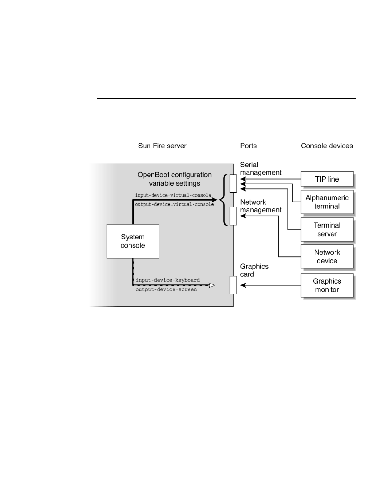
You must also ensure that the system console is directed to the appropriate port on
the server’s back panel, generally, the one to which your hardware console device is
attached (see
FIGURE 1-2). You do this by setting the input-device and output-
device OpenBoot™ configuration variables.
Note – The connectors in FIGURE 1-2 are not representative of the physical location of
the connectors on the server.
FIGURE 1-2 Directing the System Console
Connecting Through the Serial Management and Network
Management Ports
On Sun Fire V215 and V245 servers, the system console comes preconfigured. Input
and output is enabled only by means of hardware devices connected to the serial or
network management ports. However, because the network management port is not
available until you assign it an IP address, your first connection must be to the serial
management port (SER MGT).
Chapter 1 Performing General Administrative Tasks 5
Page 22

Typically, you connect one of the following hardware devices to the serial
management port:
■ Terminal server
■ Alphanumeric terminal or similar device
■ TIP line connected to another Sun computer
This provides for secure access at the installation site.
Using a TIP line enables you to use windowing and operating system features on the
system making the connection to the server.
The serial management port is not a general-purpose serial port. If you want to use
a general-purpose serial port with your server, to connect a serial printer, for
instance, use the SER TTYB serial port on the back panel of the server. The Solaris OS
sees this port as TTYB.
After you have assigned an IP address to the network management port (NET
MGT), you can connect an Ethernet-capable device to the system console through
your network. This provides for remote monitoring and control. In addition, up to
eight simultaneous connections to the system controller sc> prompt are available
through the network management port.
Configuring an Alternative System Console
In the default configuration, system controller alerts and system console output
appear interspersed in the same window. After initial system installation, you can
redirect the system console to take its input from and send its output to a graphics
card’s port.
For the following reasons, the best practice is to leave the console port in its default
configuration:
■ In a default configuration, the serial management and network management ports
enable you to open up to eight additional windows through which you can view,
but not affect, system console activity. You cannot open these connections if the
system console is redirected to a graphics card’s port.
■ In a default configuration, the serial management and network management ports
enable you to switch between viewing system console and system controller
output on the same device by typing a simple escape sequence or command. The
escape sequence and command do not work if the system console is redirected to
a graphics card’s port.
6 Sun Fire V215 and V245 Servers Administration Guide • September 2006
Page 23

■ The system controller keeps a log of console messages, but some messages are not
logged if the system console is redirected to a graphic card’s port. The omitted
information could be important if you need to contact Sun customer service with
a problem.
You change the system console configuration by setting OpenBoot configuration
variables. See “Using the OpenBoot Configuration Variables” on page 15.
Accessing the System Console Through a Graphics Monitor
The Sun Fire V215 and V245 servers are shipped without a mouse, keyboard,
monitor, or frame buffer for the display of bitmapped graphics. To install a graphics
monitor on the server, you must install a graphics accelerator card into a PCI slot,
and attach a monitor, mouse, and keyboard to the appropriate front or rear USB
ports.
After starting the system, you might need to install the correct software driver for
the PCI card you have installed. For detailed hardware instructions, see “Accessing
the System Console Through a Local Graphics Monitor” on page 13.
Note – POST diagnostics cannot display status and error messages to a local
graphics monitor.
Connecting to the System Console
Output from POST, OpenBoot, and the Solaris OS is displayed in the system console
using the network console on the system controller. Use the following procedure to
connect to the system console.
▼ To Connect to the System Console
● Execute the console command, and use the –f option to force the console to be
attached to your session.
Multiple users can be connected to the console, but only one can be attached.
sc> console –f
Enter #. to return to ALOM.
Chapter 1 Performing General Administrative Tasks 7
Page 24
Accessing the System Console Through a
Terminal Server
The following procedure assumes that you are accessing the system console by
connecting a terminal server to the serial management port (SER MGT) of the server.
Note – The figure in this section shows the Sun Fire V245 server; however, the
procedure applies to the Sun Fire V215 as well.
▼ To Access The System Console Through a Terminal Server
1. Complete the physical connection from the serial management port to your
terminal server.
The serial management port on the server is a data terminal equipment (DTE) port.
The pinouts for the serial management port correspond with the pinouts for the RJ45 ports on the Serial Interface Breakout Cable supplied by Cisco for use with the
Cisco AS2511-RJ terminal server. If you use a terminal server made by another
manufacturer, check that the serial port pinouts of the server match those of the
terminal server you plan to use.
■ If the pinouts for the server serial ports correspond with the pinouts for the RJ-45
ports on the terminal server, you have two connection options:
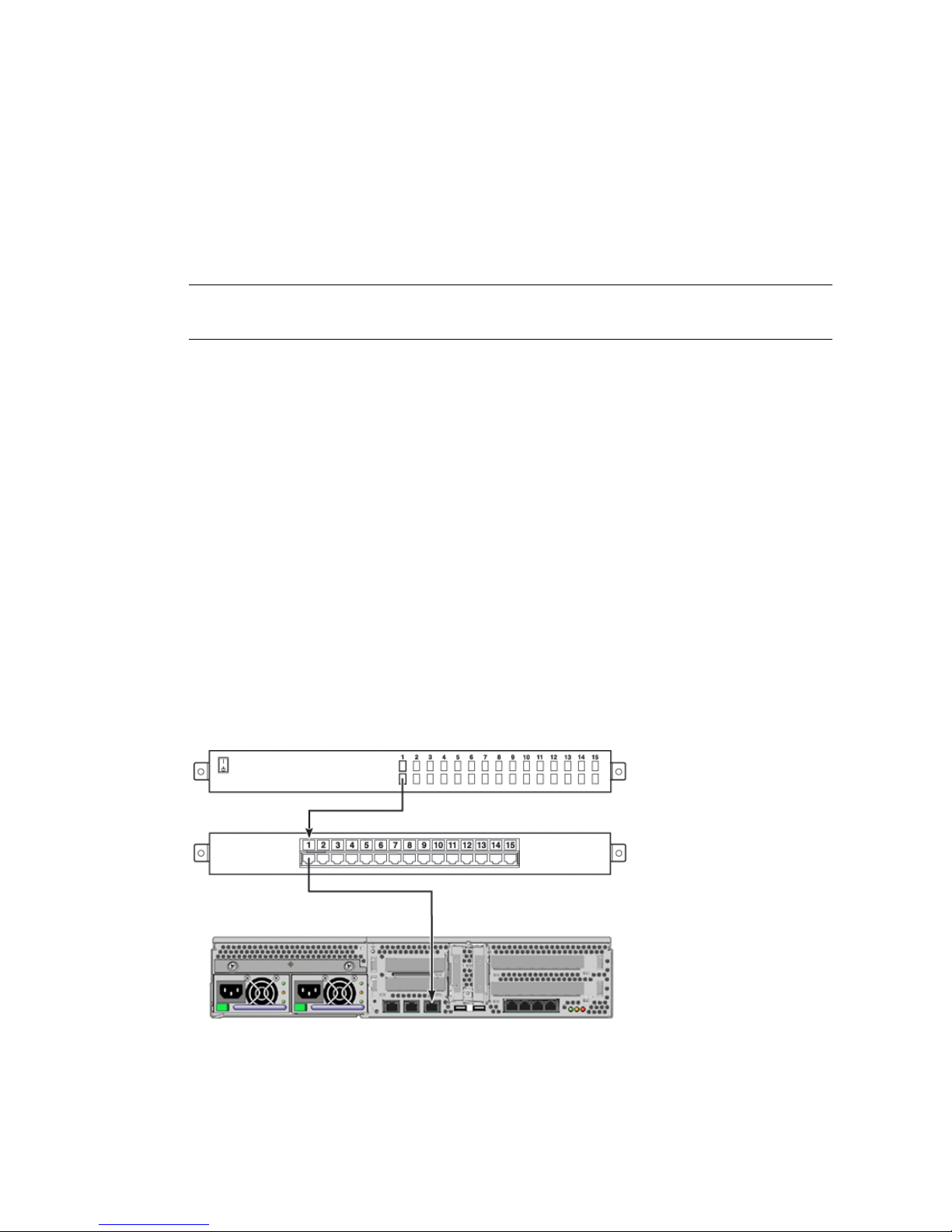
■ Connect a serial interface breakout cable directly to the server.
■ Connect a serial interface breakout cable to a patch panel and use the straight-
through patch cable (supplied by Sun) to connect the patch panel to the server.
FIGURE 1-3 Patch Panel Connection Between a Terminal Server and a Sun Fire V245
Server
8 Sun Fire V215 and V245 Servers Administration Guide • September 2006
Page 25
■ If the pinouts for the serial management port do not correspond with the
pinouts for the RJ-45 ports on the terminal server, you need to make a crossover cable that takes each pin on the serial management port to the
corresponding pin in the terminal server’s serial port.
TABLE 1-1 shows the cross-overs that the cable must perform.
TABLE 1-1 Pin Crossovers for Connecting to a Typical Terminal Server
Sun Fire V245 Serial Port (RJ-45 Connector) Pin Terminal Ser ver Serial Port Pin
Pin 1 (RTS) Pin 1 (CTS)
Pin 2 (DTR) Pin 2 (DSR)
Pin 3 (TXD) Pin 3 (RXD)
Pin 4 (Signal Ground) Pin 4 (Signal Ground)
Pin 5 (Signal Ground) Pin 5 (Signal Ground)
Pin 6 (RXD) Pin 6 (TXD)
Pin 7 (DSR /DCD) Pin 7 (DTR)
Pin 8 (CTS) Pin 8 (RTS)
2. Open a terminal session on the connecting device, and type:
% telnet IP-address-of-terminal-server port-number
For example, for a server connected to port 10000 on a terminal server whose IP
address is 192.20.30.10, you would type:
% telnet 192.20.30.10 10000
Accessing the System Console Through a TIP
Connection
This procedure assumes that you are accessing the system console by connecting the
serial port of another Sun system to the serial management port of the Sun Fire V245
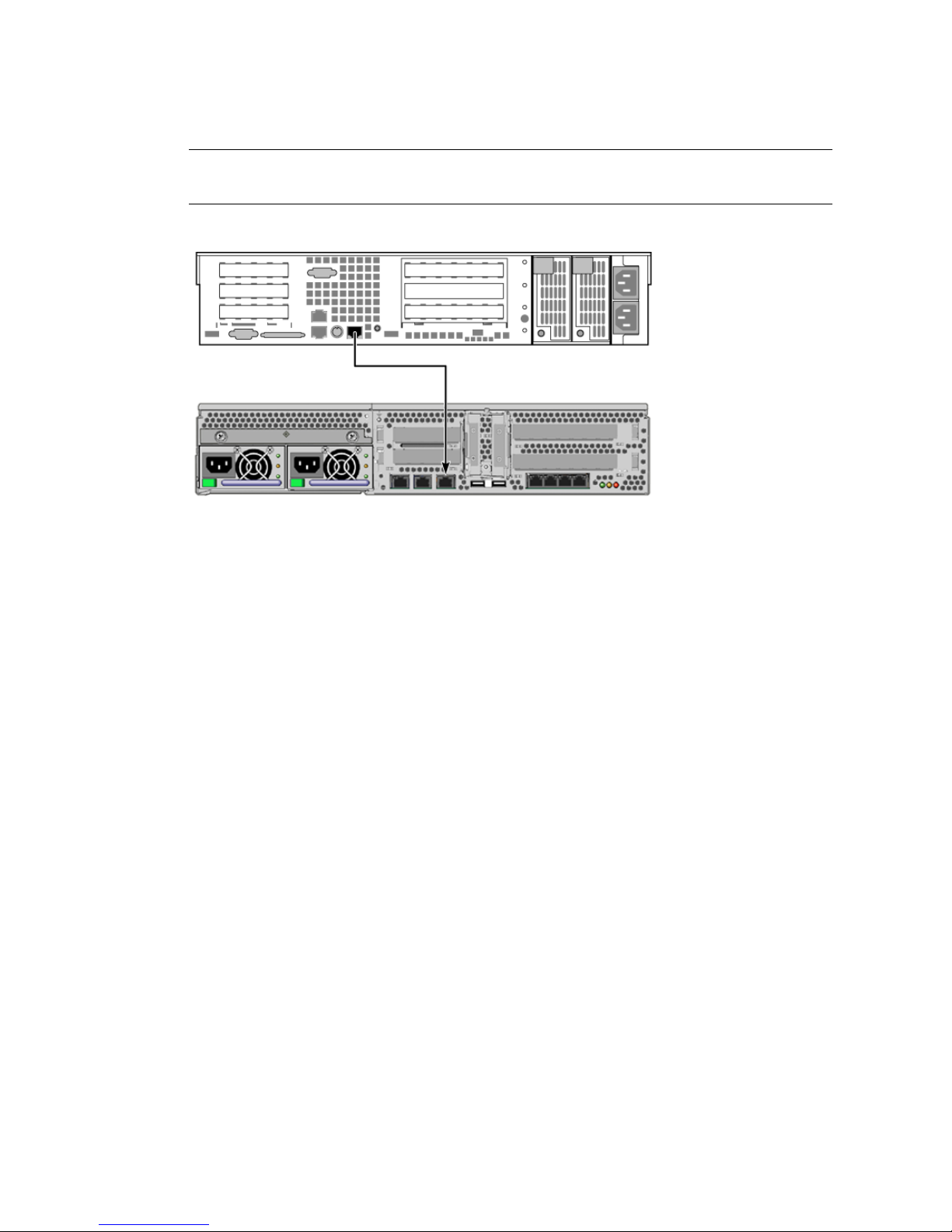
server (
FIGURE 1-4).
Chapter 1 Performing General Administrative Tasks 9
Page 26
Note – The figure in this section shows the Sun Fire V245 server; however, the
procedure applies to the Sun Fire V215 as well.
FIGURE 1-4 TIP Connection Between a Sun Fire V245 Server and Another Sun System
▼ To Access the System Console Through the TIP Connection
1. Connect the RJ-45 serial cable.
The cable and adapter connect between another Sun system’s serial port (typically
TTYB) and the serial management port on the rear panel of the server.
2. Ensure that the /etc/remote file on the Sun system contains an entry for
hardwire.
Most releases of Solaris OS software shipped since 1992 contain an /etc/remote
file with the appropriate hardwire entry. However, if the Sun system is running an
older version of Solaris OS software, or if the /etc/remote file has been modified,
you might need to edit it. See “Modifying the /etc/remote File” on page 11 for
details.
10 Sun Fire V215 and V245 Servers Administration Guide • September 2006
Page 27
3. In a shell tool window on the Sun system, type:
% tip hardwire
The Sun system responds by displaying:
connected
The shell tool is now a TIP window directed to the server through the Sun system’s
serial port. This connection is established and maintained even when the server is
completely powered off or just powering on.
Note – Use a shell tool or a CDE terminal (such as dtterm), not a command tool.
Some tip(1) commands might not work properly in a command tool window.
Modifying the /etc/remote File
This procedure might be necessary if you are accessing the server using a TIP
connection from a Sun system running an older version of the Solaris OS software.
You might also need to perform this procedure if the /etc/remote file on the Sun
system has been altered and no longer contains an appropriate hardwire entry.
This procedure assumes that you are logged in as superuser to the system console of
a Sun system that you intend to use to establish a TIP connection to the Sun Fire
V245 server.
▼ To Modify the /etc/remote File
1. Determine the release level of Solaris OS software installed on the Sun system.
Type:
# uname -r
The system responds with a release number.
2. Take one of the following actions, depending on the number displayed.
Chapter 1 Performing General Administrative Tasks 11
Page 28

■ If the number displayed by the uname -r command is 5.0 or higher:
The Solaris OS software shipped with an appropriate entry for hardwire in the
/etc/remote file. If you have reason to suspect that this file was altered and the
hardwire entry was modified or deleted, check the entry against the following
example, and edit it as needed.
hardwire:\
:dv=/dev/term/b:br#9600:el=^C^S^Q^U^D:ie=%$:oe=^D:
Note – If you intend to use the Sun system’s serial port A rather than serial port B,
edit this entry by replacing /dev/term/b with /dev/term/a.
■ If the number displayed by the uname -r command is less than 5.0:
Check the /etc/remote file and add the following entry, if it does not already
exist.
hardwire:\
:dv=/dev/ttyb:br#9600:el=^C^S^Q^U^D:ie=%$:oe=^D:
Note – If you intend to use the Sun system’s serial port A rather than serial port B,
edit this entry by replacing /dev/ttyb with /dev/ttya.
The /etc/remote file is now properly configured. Continue establishing a TIP
connection to the system console. See “Accessing the System Console Through a TIP
Connection” on page 9.
If you have redirected the system console to TTYB and want to change the system
console settings back to use the serial management and network management ports,
see “Using the OpenBoot Configuration Variables” on page 15.
Accessing the System Console Through an
Alphanumeric Terminal
This procedure assumes that you are accessing the system console by connecting the
serial port of an alphanumeric terminal to the serial management port of the Sun
Fire V245 server.
12 Sun Fire V215 and V245 Servers Administration Guide • September 2006
Page 29

▼ To Access the System Console Through an Alphanumeric
Terminal
1. Attach one end of the serial cable to the alphanumeric terminal’s serial port.
Use a null modem serial cable or an RJ-45 serial cable and null modem adapter.
Connect this cable to the terminal’s serial port connector.
2. Attach the opposite end of the serial cable to the serial management port on the
server.
3. Connect the alphanumeric terminal’s power cord to an AC outlet.
4. Set the alphanumeric terminal to receive:
■ 9600 baud
■ 8 bits
■ No parity
■ 1 stop bit
■ No handshake protocol
Refer to the documentation accompanying your terminal for information about how
to configure the terminal.
You can issue system commands and view system messages using the alphanumeric
terminal. Continue with your installation or diagnostic procedure, as needed. When
you are finished, type the alphanumeric terminal’s escape sequence.
Accessing the System Console Through a Local
Graphics Monitor
After initial system installation, you can install a local graphics monitor and
configure it to access the system console. You cannot use a local graphics monitor to
perform initial system installation, nor can you use a local graphics monitor to view
power-on self-test (POST) messages.
To install a local graphics monitor, you must have the following items:
■ Supported PCI-based graphics frame buffer card and software driver
■ Monitor with appropriate resolution to support the frame buffer
■ Sun compatible USB keyboard (Sun USB Type 7 keyboard)
■ Sun compatible USB mouse (Sun USB mouse) and mouse pad
Chapter 1 Performing General Administrative Tasks 13
Page 30
▼ To Access the System Console Through a Local Graphics
Monitor
1. Install the graphics card into an appropriate PCI slot.
Installation must be performed by a qualified service provider. For further
information, refer to the Sun Fire V215 and V245 Servers Service Manual or contact
your qualified service provider.
2. Attach the monitor’s video cable to the graphics card’s video port.
Tighten the thumbscrews to secure the connection.
3. Connect the monitor’s power cord to an AC outlet.
4. Connect the USB keyboard cable to one of the USB ports on the rear panel and the
USB mouse cable to the USB port on the keyboard.
5. Obtain the ok prompt.
6. Set OpenBoot configuration variables, as appropriate.
If you have changed the default input and output devices, change the settings back
to the defaults by typing:
ok setenv input-device keyboard
ok setenv output-device screen
Note – There are many other system configuration variables. Although these
variables do not affect which hardware device is used to access the system console,
some of them affect which diagnostic tests the system runs and which messages the
system displays at its console.
7. To cause the changes to take effect, type:
ok reset-all
The system stores the parameter changes, and boots automatically when the
OpenBoot configuration variable auto-boot? is set to true (the default value).
Note – To store parameter changes, you can also power cycle the system using the
front panel Power button.
14 Sun Fire V215 and V245 Servers Administration Guide • September 2006
Page 31

You can issue system commands and view system messages using your local
graphics monitor. If you want to redirect the system console back to the serial
management and network management ports, see “Using the OpenBoot
Configuration Variables” on page 15.
Using the OpenBoot Configuration Variables
The system console is directed to the serial management and network management
ports (SER MGT and NET MGT). If you have connected a graphics monitor the
output is directed to that device by default. You can also redirect the system console
back to the serial management and network management ports.
Certain OpenBoot configuration variables control from where system console input
is taken and to where its output is directed. The following table shows how to set
these variables in order to use the serial management and network management
ports, or a local graphics monitor as the system console connection.
TABLE 1-2 OpenBoot Configuration Variables That Affect the System Console
Setting for Sending System Console Output to:
OpenBoot Configuration
Variable Name
Serial and
Network Management Ports
Local Graphics Monitor/USB Keyboard
and Mouse
*
output-device virtual-console screen
input-device virtual-console keyboard
* POST output is still directed to the serial management port, as POST has no mechanism to direct its output to a
graphics monitor.
The serial management port does not function as a standard serial connection. If you
want to connect a conventional serial device (such as a printer) to the system, you
must connect it to TTYA not the serial management port.
It is important to note that the sc> prompt and POST messages are only available
through the serial management port and network management port. In addition, the
ALOM console command is ineffective when the system console is redirected to a
local graphics monitor.
Chapter 1 Performing General Administrative Tasks 15
Page 32
Switching Between the ALOM System Controller
and the System Console
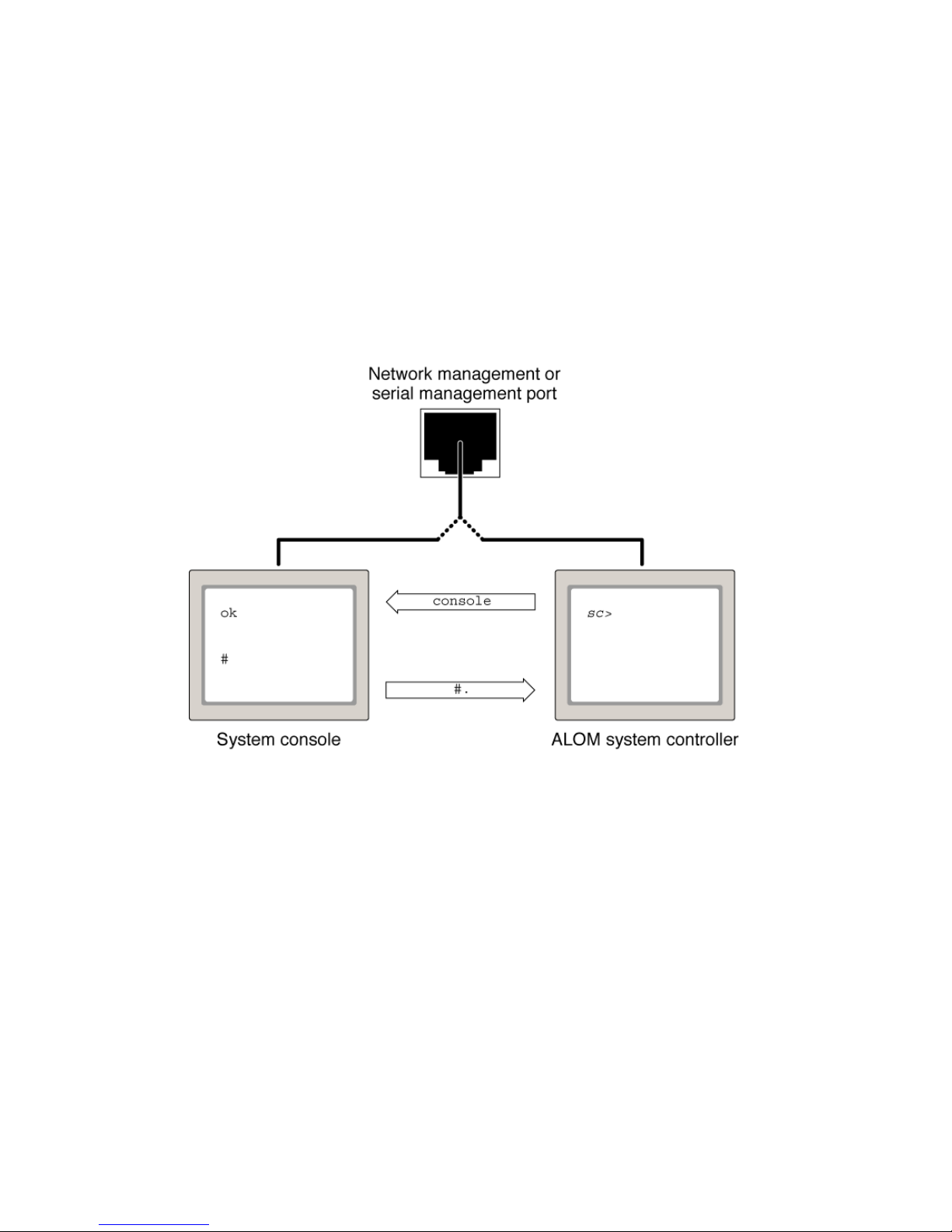
The Sun Fire V215 and V245 servers feature two management ports, labeled SER
MGT and NET MGT, located on the server’s rear panel. If the system console is
directed to use the serial management and network management ports, these ports
provide access to both the system console and the ALOM, each on a separate
channel (see
FIGURE 1-5).
FIGURE 1-5 Separate System Console and System Controller Channels
If the system console is configured to be accessible from the serial management and
network management ports, when you connect through one of these ports you can
access either the ALOM command-line interface or the system console. You can
switch between the ALOM interface and the system console at any time, but you
cannot access both at the same time from a single terminal window or shell tool.
The prompt displayed on the terminal or shell tool tells you which channel you are
accessing:
■ The # or % prompt indicates that you are at the system console and that the
Solaris OS is running.
■ The ok prompt indicates that you are at the system console and that the server is
running under OpenBoot firmware control.
■ The sc> prompt indicates that you are at the ALOM system controller.
16 Sun Fire V215 and V245 Servers Administration Guide • September 2006
Page 33
Note – If no text or prompt appears, it might be that no console messages were
recently generated by the system. If this happens, pressing the terminal’s Enter or
Return key should produce a prompt.
To reach the system console from the ALOM system controller, type the console
command at the sc> prompt. To reach the ALOM system controller from the system
console, type the system controller escape sequence, which by default is #. (pound
period).
Resetting the Server
At times, you might need to reset the server. Follow the instructions in this section to
do so. If the server is not responding to the reset, you will have to cycle the power.
This section includes a procedure to cycle the power.
▼ To Reset the Server
● If it is necessary to reset the server, use the uadmin command.
# uadmin 2 1
To simply reset the server, it is not necessary to power the system off and on.
▼ To Power Cycle the Server
If a simple reset does not clear a problem, you can power the server off and on with
this procedure.
1. Shut down the Solaris OS.
Chapter 1 Performing General Administrative Tasks 17
Page 34
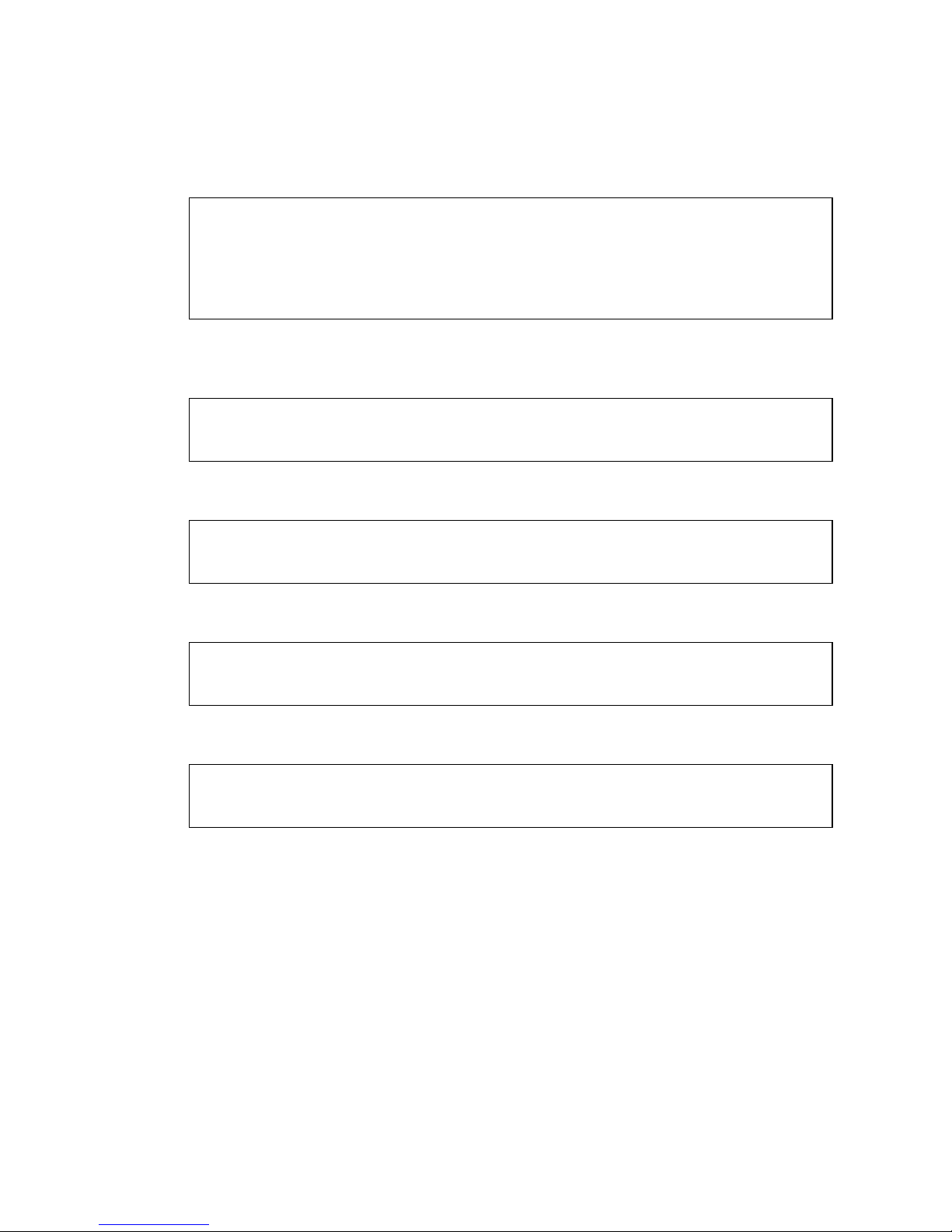
At the Solaris OS prompt, issue the uadmin command to halt the Solaris OS and to
return to the ok prompt.
# uadmin 2 0
WARNING: proc_exit: init exited
syncing file systems... done
Program terminated
ok
2. Switch from the system console prompt to the SC console prompt by issuing the
#. escape sequence.
ok #.
sc>
3. Issue the poweroff command.
sc> poweroff -fy
SC Alert: SC Request to Power Off Host Immediately.
4. Issue the poweron command.
sc> poweron
sc> SC Alert: Host System has Reset
5. Reconnect to the system console using the console command.
sc> console -f
Enter #. to return to ALOM.
The server outputs various messages, followed by the ok prompt.
18 Sun Fire V215 and V245 Servers Administration Guide • September 2006
Page 35
Controlling the Locator Indicator
This section explains how to turn the Locator indicator on and off and how to check
the status of the Locator indicator.
▼ To Turn the Locator Indicator On
● Do one of the following:
■ As superuser, type:
# /usr/sbin/locator -n
■ At the ALOM command-line interface, type:
sc> setlocator on
▼ To Turn the Locator Indicator Off
● Do one of the following:
■ As superuser, type:
# /usr/sbin/locator -f
■ At the ALOM command-line interface, type:
sc> setlocator off
Chapter 1 Performing General Administrative Tasks 19
Page 36
▼ To Display Locator Indicator Status
● Do one of the following:
■ As superuser, type:
# /usr/sbin/locator
■ At the ALOM command-line interface, type:
sc> showlocator
Selecting a Boot Device
The boot device is specified by the setting of an OpenBoot configuration variable
called boot-device. The default setting of this variable is disk net. Because of
this setting, the firmware first attempts to boot from the system hard drive, and if
that fails, from the on-board NET0 Gigabit Ethernet interface.
This procedure assumes that you are familiar with the OpenBoot firmware and that
you know how to enter the OpenBoot environment. If you want to boot from a
networked device, you must connect the network interface to the network.
▼ To Select a Boot Device
● At the ok prompt, type:
ok setenv boot-device device-specifier
where device-specifier is one of the following:
■ cdrom – Specifies the DVD super multi drive.
■ disk – Specifies the system boot disk (internal disk 0 by default).
■ disk0 – Specifies internal drive 0.
■ disk1 – Specifies internal drive 1.
■ disk2 – Specifies internal drive 2.
■ disk3 – Specifies internal drive 3.
■ net, net0, net1, net2, net3 – Specifies the network interfaces.
■ full path name – Specifies the device or network interface by its full path name.
20 Sun Fire V215 and V245 Servers Administration Guide • September 2006
Page 37

Note – The Solaris OS modifies the boot-device variable to its full path name, not
the alias name. If you choose a nondefault boot-device variable, the Solaris OS
specifies the full device path of the boot device.
Note – You can specify the name of the program to be booted as well as the way the
boot program operates. For more information, refer to the OpenBoot 4.x Command
Reference Manual for your specific Solaris OS release.
If you want to specify a network interface other than an on-board Ethernet interface
as the default boot device, you can determine the full path name of each interface by
typing:
ok show-devs
The show-devs command lists the system devices and displays the full path name
of each PCI device.
Updating the Firmware
The flashupdate command updates both the service processor firmware and the
host firmware.
The flash image consists of the following components:
■ System controller firmware
■ OpenBoot PROM
■ POST
■ Reset/config
■ Sequencer
■ Partition description
To use the features and fixes in subsequent firmware releases, perform this
procedure.
Chapter 1 Performing General Administrative Tasks 21
Page 38

▼ To Update the Firmware
1. Ensure that the SC Ethernet management port is configured.
This is required to access the new flash image over the network.
2. Open a Telnet session and connect to the system controller, as in the following
example.
% alternate 129.xxx.xx.xx
Trying 129.xxx.xx.xx...
Connected to 129.xxx.xx.xx.
Escape character is’^]’.
Use is subject to license terms.
Symptom) Advanced Lights Out Manager 1.0.11 ()
Please login:
Substitute the IP address of your system controller.
3. Login as admin, using the password you defined during the configuration of the
system controller.
Please login: admin
Please Enter password: password
sc>
4. Execute flashupdate command.
The flashupdate SC command updates the system controller flash image. The
flashupdate command requires the following information:
■ IP address of a system on the network that can access the flash image.
■ The full pathname to the flash image that the IP address specified above can
access.
■ The username and password of an account registered on the system specified by
the IP address used above.
22 Sun Fire V215 and V245 Servers Administration Guide • September 2006
Page 39
The command usage is as follows:
flashupdate [-s IP-address -f pathname] [-v]
■ -s IP-address is the IP address of any system on the network that can access the
flash image.
■ -f pathname is the full pathname to the flash image.
■ -v is the flag to turn on verbose message output.
sc> flashupdate -s 129.xxx.xx.xx -f / net/server_name/directory_path/
combined-OSP-image-1.0.7
Username: debug
Password: password
............................................................... .
Update complete. Reset device to use new image.
sc>
5. Reset the system controller.
After the flash has been updated, you must reset the system controller for the new
image to take effect. To reset the system controller, issue the resetsc command.
When you issue this command, you will be prompted to confirm that you want to
reset the system controller. Reply y when prompted.
Note – To bypass the confirmation prompt, you can use the -y flag with the
resetsc command. If resetsc is issued from a Telnet session, upon reset the
Telnet session will be terminated. The output from the reset will be displayed on the
serial console on the system controller.
sc> resetsc
Are you sure you want to reset the SC [y/n]? y
User Requested SC Shutdown
Chapter 1 Performing General Administrative Tasks 23
Page 40

The system controller resets, runs diagnostics, and returns to the login prompt. The
following example is for the serial console.
ALOM POST 1.0
Dual Port Memory Test, PASSED.
TTY External - Internal Loopback Test
TTY External - Internal Loopback Test, PASSED.
TTYC - Internal Loopback Test
TTYC - Internal Loopback Test, PASSED.
TTYD - Internal Loopback Test
TTYD - Internal Loopback Test, PASSED.
....................
Full VxDiag Tests - PASSED
Status summary - Status = 7FFF
VxDiag - - PASSED
POST - - PASSED
LOOPBACK - - PASSED
I2C - - PASSED
EPROM - - PASSED
FRU PROM - - PASSED
ETHERNET - - PASSED
MAIN CRC - - PASSED
BOOT CRC - - PASSED
TTYD - - PASSED
TTYC - - PASSED
MEMORY - - PASSED
MPC885 - - PASSED
Please login:
24 Sun Fire V215 and V245 Servers Administration Guide • September 2006
Page 41

CHAPTER
2
Sun Advanced Lights Out Manager
This chapter gives an overview of the Sun Advanced Lights Out Manager (ALOM)
software. The chapter contains:
■ “New ALOM Features” on page 25
■ “Setting the admin Password” on page 26
ALOM enables you to monitor and control your server through a serial connection
(using the SER MGT port), or Ethernet connection (using the NET MGT port).
The ALOM serial port, labelled SER MGT, is for server management only. If you
need a general purpose serial port, use the serial port labeled SER TTYB.
If you use ALOM to reset the server and the diag-switch? is set to true, the
bootscript command is not executed when the server reboots. If you use
OpenBoot PROM to reset the server, bootscript executes correctly.
When you issue the showfru command from the ALOM command shell, the
command does not read the layout of the DIMMs.
When OpenBoot PROM reports DIMM errors to ALOM, it sends system console (SC)
alert messages with the incorrect memory slot position for the Sun Fire V215 and
V245 servers. However the memory errors are still valid.
New ALOM Features
This release of the Sun Fire V215 and V245 servers includes several new ALOM
features and enhancements. ALOM can now:
■ Support a virtual keyswitch that provides the functions formerly provided by the
front-panel keyswitch.
■ Use the Secure Shell (SSH) protocol for network communication.
■ Support for the SNMP protocol.
25
Page 42
■ Periodically record the set of FRUs installed in the server.
This information is kept in nonvolatile storage. You can inspect the log to
determine if the hardware components have been changed.
■ Store traffic sent to the system console in nonvolatile storage.
■ Store the event log in nonvolatile storage.
■ Support the scadm command to display the ALOM FRU information log, system
console log, and log history.
■ Periodically log system environmental data (including, temperature and power
supply information) to the dynamic region of the FRU ID PROMs.
You can retrieve this information by using the showfru command or the prtfru
command.
■ Support an electronically-readable chassis serial number.
The serial number is stored in nonvolatile storage during manufacturing. ALOM
can display this value and provide a service-mode command that can change it, if
necessary. The prtdiag command can also display this value.
■ Maintain the installation information in the dynamic portion of the FRU ID
PROMs.
The installation information includes the location of FRUs within the chassis, as
well as the identification of the chassis and FRU.
Setting the admin Password
When you switch to the ALOM prompt after initial power on, you are logged in as
the admin user and prompted to set a password. You must set this password in
order to execute certain commands.
If you are prompted to do so, set a password for the admin user.
The password must:
■ Contain at least two alphabetic characters.
■ Contain at least one numeric or one special character.
■ Be at least six characters long.
After the password is set, the admin user has full permissions and can execute all
ALOM CLI commands.
26 Sun Fire V215 and V245 Servers Administration Guide • September 2006
Page 43

Tip – If you log in to ALOM with a 16-character user name and execute the
showusers command, ALOM enters a loop and refuses all other connection
attempts. If you encounter this problem, establish a Telnet connection to the host
server and use the scadm resetrsc command to reset ALOM.
Chapter 2 Sun Advanced Lights Out Manager 27
Page 44

28 Sun Fire V215 and V245 Servers Administration Guide • September 2006
Page 45

CHAPTER
3
SunVTS
The Sun Validation and Test Suite (SunVTS) is a software suite that performs system,
subsystem, and configuration testing. You can view and control a SunVTS session
over a network. Using a remote system, you can view the progress of a testing
session, change testing options, and control all testing features of another machine
on the network.
The following topics are discussed:
■ “SunVTS Test Modes” on page 29
■ “SunVTS Software and Security” on page 30
■ “SunVTS Installation” on page 30
■ “SunVTS Documentation” on page 31
SunVTS Test Modes
You can run SunVTS software in five different test modes:
■ Connection test mode, which provides a low-stress, quick test of the availability and
connectivity of selected devices. These tests are nonintrusive, meaning that they
release the devices after a quick test and do not place a heavy load on the system.
■ Functional test mode, which provides a robust test of the system and devices. This
test mode uses the system resources for thorough testing, and it assumes that no
other applications are running. This mode is the default test mode.
■ Exclusive test mode, which enables you to perform the tests that require no other
SunVTS or applications running at the same time.
■ Online test mode, which enables you to perform SunVTS testing while applications
are running.
■ Auto Config mode, which simplifies the SunVTS configuration process by
automatically assigning a predetermined set of test options.
29
Page 46
Because SunVTS software can run many tests in parallel and consume many system
resources, you should take care when using it on a production system. If you are
stress-testing a system using SunVTS software’s Comprehensive test mode, do not
run anything else on that system at the same time.
A server must be running the Solaris OS for SunVTS software to be able to test it.
Because the SunVTS software packages are optional, they may not be installed on
your system. See “SunVTS Installation” on page 30 for instructions.
SunVTS Software and Security
During SunVTS software installation, you must choose between Basic or Sun
Enterprise Authentication Mechanism
file in the SunVTS installation directory to limit the users, groups, and hosts
permitted to use SunVTS software. Sun Enterprise Authentication Mechanism
security is based on the standard network authentication protocol Kerberos and
provides secure user authentication, data integrity, and privacy for transactions over
networks.
If your site uses Sun Enterprise Authentication Mechanism security, you must have
Sun Enterprise Authentication Mechanism client and server software installed on
your network and configured properly in both Solaris and SunVTS software. If your
site does not use Sun Enterprise Authentication Mechanism security, do not choose
the Sun Enterprise Authentication Mechanism option during SunVTS software
installation.
If you enable the wrong security scheme during installation, or if you improperly
configure the security scheme you choose, you might find yourself unable to run
SunVTS tests. For more information, see the SunVTS User’s Guide and the
instructions accompanying the Sun Enterprise Authentication Mechanism software.
™
security. Basic security uses a local security
SunVTS Installation
The SunVTS software is installed as part of the preinstalled software image on the
Sun Fire V215 and V245 servers. However, it is available on the software supplement
CD supplied with the Solaris OS. For information about downloading it from this
CD, refer to the Sun Hardware Platform Guide for the release of the Solaris OS you are
using.
30 Sun Fire V215 and V245 Servers Administration Guide • September 2006
Page 47

To find out more about using the SunVTS software, refer to the SunVTS
documentation that corresponds to the Solaris OS release that you are running.
SunVTS Documentation
SunVTS documents are included on the Software Supplement CD that is part of each
Solaris Media Kit release and is also accessible at: http://docs.sun.com
For further information, you can also consult the following SunVTS documents:
■ SunVTS User’s Guide describes how to install, configure, and run the SunVTS
diagnostic software.
■ SunVTS Quick Reference Card provides an overview of how to use the SunVTS
CDE interface.
■ SunVTS Test Reference Manual provides details about each individual SunVTS test.
Chapter 3 SunVTS 31
Page 48

32 Sun Fire V215 and V245 Servers Administration Guide • September 2006
Page 49

CHAPTER
4
Managing RAS Features and System
Firmware
This chapter describes how to manage reliability, availability, and serviceability
(RAS) features and system firmware, including the Sun Advanced Lights Out
Manager (ALOM) system controller, and automatic system recovery (ASR). In
addition, this chapter describes how to unconfigure and reconfigure a device
manually, and introduces multipathing software.
This chapter contains the following sections:
■ “OpenBoot Emergency Procedures” on page 33
■ “Automatic System Recovery” on page 35
■ “Displaying System Fault Information” on page 37
■ “Multipathing Software” on page 38
OpenBoot Emergency Procedures
The introduction of universal serial bus (USB) keyboards with the newest Sun
systems has made it necessary to change some of the OpenBoot emergency
procedures. Specifically, the Stop-N, Stop-D, and Stop-F commands that were
available on systems with non-USB keyboards are not supported on systems that use
USB keyboards, such as the Sun Fire server. If you are familiar with the earlier (nonUSB) keyboard functionality, this section describes the analogous OpenBoot
emergency procedures available in newer systems that use USB keyboards.
33
Page 50
OpenBoot Emergency Procedures
The following sections describe how to perform the functions of the Stop commands
on systems that use USB keyboards. These same functions are available through the
ALOM software.
Stop-A Functionality
Stop-A (Abort) key sequence works the same as it does on systems with standard
keyboards, except that it does not work during the first few seconds after the server
is reset. In addition, you can issue the ALOM system controller break command.
Stop-N Functionality
Stop-N functionality is not available. However, the Stop-N functionality can be
closely emulated by completing the following steps, provided the system console is
configured to be accessible using either the serial management port or the network
management port.
▼ To Restore OpenBoot Configuration Defaults
1. Log in to the ALOM system controller.
2. Type the following commands:
sc> bootmode reset_nvram
sc> bootmode bootscript="setenv auto-boot? false"
sc>
Note – If you do not issue the poweroff and poweron commands or the reset
command within 10 minutes, the host server ignores the bootmode command.
You can issue the bootmode command without arguments to display the current
setting.
sc> bootmode
Bootmode: reset_nvram
Expires WED SEP 09 09:52:01 UTC 2006
bootscript="setenv auto-boot? false"
34 Sun Fire V215 and V245 Servers Administration Guide • September 2006
Page 51
3. To reset the system, type the following commands:
sc> reset
Are you sure you want to reset the system [y/n]? y
sc>
4. To view console output as the system boots with default OpenBoot configuration
variables, switch to console mode.
sc> console
ok
5. Type set-defaults to discard any customized IDPROM values and to restore
the default settings for all OpenBoot configuration variables.
Stop-F Functionality
The Stop-F functionality is not available on systems with USB keyboards.
Stop-D Functionality
The Stop-D (Diags) key sequence is not supported on systems with USB keyboards.
However, the Stop-D functionality can be closely emulated by setting the virtual
keyswitch to diag, using the ALOM setkeyswitch command.
Automatic System Recovery
The system provides for automatic system recovery (ASR) from failures in memory
modules or PCI cards.
Automatic system recovery functionality enables the system to resume operation
after experiencing certain nonfatal hardware faults or failures. When ASR is enabled,
the firmware diagnostics automatically detect failed hardware components. An
autoconfiguring capability designed into the system firmware enables the system to
unconfigure failed components and to restore system operation. As long as the
system is capable of operating without the failed component, the ASR features
enable the system to reboot automatically, without operator intervention.
Chapter 4 Managing RAS Features and System Firmware 35
Page 52
Autoboot Options
The system firmware stores a configuration variable called auto-boot?, which
controls whether the firmware will automatically boot the operating system after
each reset. The default setting for Sun platforms is true.
Normally, if a system fails power-on diagnostics, auto-boot? is ignored and the
system does not boot unless an operator boots the system manually. An automatic
boot is not acceptable for booting a system in a degraded state. Therefore, the Sun
Fire server OpenBoot firmware provides a second setting, auto-boot-on-error?.
This setting controls whether the system will attempt a degraded boot when a
subsystem failure is detected. Both the auto-boot? and auto-boot-on-error?
switches must be set to true to enable an automatic degraded boot. To set the
switches, type:
ok setenv auto-boot? true
ok setenv auto-boot-on-error? true
Note – The default setting for auto-boot-on-error? is true. Therefore, the
system attempts a degraded boot unless you change this setting to false.In
addition, the system will not attempt a degraded boot in response to any fatal
nonrecoverable error, even if degraded booting is enabled. For examples of fatal
nonrecoverable errors, see “Error Handling Summary” on page 36.
Error Handling Summary
Error handling during the power-on sequence falls into one of the following three
cases:
■ If no errors are detected by POST or OpenBoot firmware, the system attempts to
boot if auto-boot? is true.
■ If only nonfatal errors are detected by POST or OpenBoot firmware, the system
attempts to boot if auto-boot? is true and auto-boot-on-error? is true.
Nonfatal errors include the following:
■ SAS subsystem failure. In this case, a working alternate path to the boot disk is
required. For more information, see “Multipathing Software” on page 38.
■ Ethernet interface failure.
■ USB interface failure.
■ Serial interface failure.
■ PCI card failure.
36 Sun Fire V215 and V245 Servers Administration Guide • September 2006
Page 53
■ Memory failure. Given a failed DIMM, the firmware will unconfigure the entire
logical bank associated with the failed module. Another nonfailing logical bank
must be present in the system for the system to attempt a degraded boot.
Note – If POST or OpenBoot firmware detects a nonfatal error associated with the
normal boot device, the OpenBoot firmware automatically unconfigures the failed
device and tries the next-in-line boot device, as specified by the boot-device
configuration variable.
■ If a fatal error is detected by POST or OpenBoot firmware, the system does not
boot regardless of the settings of auto-boot? or auto-boot-on-error?. Fatal
nonrecoverable errors include the following:
■ Any CPU failed
■ All logical memory banks failed
■ Flash RAM cyclical redundancy check (CRC) failure
■ Critical field-replaceable unit (FRU) PROM configuration data failure
■ Critical system processor read failure
■ Critical application-specific integrated circuit (ASIC) failure
Displaying System Fault Information
ALOM software lets you display current valid system faults. The showfaults
command displays the fault ID, the faulted FRU device, and the fault message to
standard output. The showfaults command also displays POST results. For
example:
sc> showfaults
ID FRU Fault
0 FT0.FM2 SYS_FAN at FT0.FM2 has FAILED.
Adding the –v option displays the time:
sc> showfaults -v
ID Time FRU Fault
0 MAY 20 10:47:32 FT0.FM2 SYS_FAN at FT0.FM2 has FAILED.
Chapter 4 Managing RAS Features and System Firmware 37
Page 54

▼ To Display System Fault Information
● At the sc> prompt, type:
sc> showfaults –v
Multipathing Software
Multipathing software enables you to define and control redundant physical paths
to I/O devices, such as storage devices and network interfaces. If the active path to
a device becomes unavailable, the software can automatically switch to an alternate
path to maintain availability. This capability is known as automatic failover. To take
advantage of multipathing capabilities, you must configure the server with
redundant hardware, such as redundant network interfaces or two host bus adapters
connected to the same dual-ported storage array.
Three different types of multipathing software are available:
■ Solaris IP Network Multipathing software provides multipathing and
load-balancing capabilities for IP network interfaces.
■ VERITAS Volume Manager (VVM) software includes a feature called Dynamic
Multipathing (DMP), which provides disk multipathing as well as disk load
balancing to optimize I/O throughput.
■ Sun StorEdge™ Traffic Manager is an architecture fully integrated within the
Solaris OS (beginning with the Solaris 8 release) that enables I/O devices to be
accessed through multiple host controller interfaces from a single instance of the
I/O device.
For More Information
For instructions on how to configure and administer Solaris IP Network
Multipathing, consult the IP Network Multipathing Administration Guide provided
with your specific Solaris release.
For information about Sun StorEdge Traffic Manager, refer to your Solaris OS
documentation.
38 Sun Fire V215 and V245 Servers Administration Guide • September 2006
Page 55

Index
Symbols
/etc/remote file, 10
modifying, 11
A
ALOM prompt, 1
alphanumeric terminal, 6
accessing system console from, 12
setting baud rate, 13
auto-boot (OpenBoot configuration variable), 36
automatic system recovery (ASR)
about, 35
B
bootmode reset_nvram (sc> command), 34
C
cables, keyboard and mouse, 14
CDE, 11
Cisco AS2511-RJ Terminal Server, connecting, 8
command prompts, explained, 16
communicating with the system
about, 4
console configuration, connection alternatives
explained, 6
D
data terminal equipment, 8
default system console configuration, 5
dtterm (Solaris OS utility), 11
E
error handling, summary, 36
G
graphics monitor
accessing system console from, 13
connecting to PCI graphics card, 14
restrictions against using for initial setup, 13
restrictions against using to view POST
output, 13
I
input-device (OpenBoot configuration
variable), 14, 15
K
keyboard, attaching, 14
M
monitor, attaching, 13
moving the system, precautions, 3
O
On/Standby button, 3
OpenBoot commands
reset-all, 14
set-defaults, 35
setenv, 14
OpenBoot configuration variables
auto-boot, 36
input-device, 14, 15
output-device, 14, 15
39
Page 56

system console settings, 15
OpenBoot emergency procedures
USB keyboard commands, 34
OpenBoot PROM prompt, 1
output-device (OpenBoot configuration
variable), 14, 15
P
parity, 13
patch panel, 8
patch panel, terminal server connection, 8
PCI, 7
PCI graphics card
configuring to access system console, 13
connecting graphics monitor to, 14
frame buffers, 13
R
reset-all (OpenBoot command), 14
RJ-45, 8, 9, 10
S
sc> commands
bootmode reset_nvram, 34
console, 35
reset, 35
sc> prompt
system console, switching between, 16
serial management port (SER MGT)
acceptable console device connections, 6
as default communication port on initial
startup, 4
default system console configuration, 5
SERIAL MGT, See serial management port
set-defaults (OpenBoot command), 35
setenv (OpenBoot command), 14
Solaris commands
tip, 9, 11
uname, 12
uname -r, 11
Stop-A (USB keyboard functionality), 34
Stop-D (USB keyboard functionality), 35
Stop-F (USB keyboard functionality), 35
Stop-N (USB keyboard functionality), 34
stress testing, See also exercising the system, 29
Sun Enterprise Authentication Mechanism
software, 30
superuser, 1
system console
accessing with alphanumeric terminal, 12
accessing with graphics monitor, 13
accessing with terminal server, 8
accessing with TIP connection, 9
accessing with tip connection, 9
alphanumeric terminal connection, 12
alternate configurations, 6
configuring local graphics monitor to access, 13
connection using graphics monitor, 7
default configuration explained, 4, 5
default connections, 5
defined, 4
graphics monitor connection, 7
setting OpenBoot configuration variables for, 15
system console sc> prompt, switching between, 16
system prompts, 1
T
terminal server
accessing system console from, 6, 8
connection through patch panel, 8
pinouts for crossover cable, 9
tip (Solaris command), 11
TIP connection
accessing system console, 9
accessing terminal server, 9
TTYA, 6
TTYB, 10
U
uname (Solaris command), 12
uname -r (Solaris command), 11
40 Sun Fire V215 and V245 Servers Administration Guide • September 2006
 Loading...