

Page 1

Sun Fire™E4900 and
Sun Fire 6800/4800 Systems
Power Supply and Fan Tray
Upgrade Guide
Preparation for UltraSPARC® IV/IV+ Based Systems
Sun Microsystems, Inc.
www.sun.com
Part No. 817-4818-15
June 2006, Revision A
Submit comments about this document at: http://www.sun.com/hwdocs/feedback
Page 2

Copyright 2006 Sun Microsystems, Inc., 4150 Network Circle,SantaClara,California95054,U.S.A.Allrightsreserved.
Sun Microsystems, Inc. has intellectual propertyrightsrelatingtotechnologythatisdescribedinthisdocument.Inparticular, and without
limitation, these intellectual property rights may include one or moreoftheU.S.patentslistedathttp://www.sun.com/patents and one or
more additional patents or pending patent applications in the U.S. and in other countries.
This document and the product to which it pertains aredistributedunderlicensesrestrictingtheiruse,copying,distribution,and
decompilation. No part of the product or of this document may be reproducedinanyformbyanymeanswithoutpriorwritten authorization of
Sun and its licensors, if any.
Third-party software, including font technology,is copyrighted and licensed from Sun suppliers.
Parts of the product may be derived from Berkeley BSD systems, licensed from the University of California. UNIX is a registered trademark in
the U.S. and in other countries, exclusively licensed through X/Open Company,Ltd.
Sun, Sun Microsystems, the Sun logo, Java, AnswerBook2, docs.sun.com, Sun Fire, and Solaris are trademarks or registered trademarks of Sun
Microsystems, Inc. in the U.S. and in other countries.
All SPARC trademarks are used under license and are trademarks or registered trademarks of SPARC International, Inc. in the U.S. and in other
countries. Products bearing SPARC trademarks are based upon an architecture developed by Sun Microsystems, Inc.
The OPEN LOOK and Sun™ Graphical User Interface was developed by Sun Microsystems, Inc. for its users and licensees. Sun acknowledges
the pioneering efforts of Xerox in researching and developing the concept of visual or graphical user interfaces for the computer industry.Sun
holds a non-exclusive license from Xerox to the Xerox Graphical User Interface, which license also covers Sun’s licensees who implement OPEN
LOOK GUIs and otherwise comply with Sun’s written license agreements.
U.S. Government Rights—Commercial use. Government users are subject to the Sun Microsystems, Inc. standard license agreement and
applicable provisions of the FAR and its supplements.
DOCUMENTATION IS PROVIDED "AS IS" AND ALL EXPRESS OR IMPLIED CONDITIONS, REPRESENTATIONS AND WARRANTIES,
INCLUDING ANY IMPLIED WARRANTYOF MERCHANTABILITY, FITNESS FOR A PARTICULAR PURPOSE OR NON-INFRINGEMENT,
ARE DISCLAIMED, EXCEPT TO THE EXTENT THAT SUCH DISCLAIMERS ARE HELD TO BE LEGALLY INVALID.
Copyright 2006 Sun Microsystems, Inc., 4150 Network Circle, Santa Clara, Californie 95054, États-Unis. Tousdroits réservés.
Sun Microsystems, Inc. possède les droits de propriété intellectuels relatifs à la technologie décrite dans ce document. En particulier, et sans
limitation, ces droits de propriété intellectuels peuvent inclure un ou plusieurs des brevets américains listés sur le site
http://www.sun.com/patents, un ou les plusieurs brevets supplémentaires ainsi que les demandes de brevet en attente aux les États-Unis et
dans d’autres pays.
Ce document et le produit auquel il se rapporte sont protégés par un copyright et distribués sous licences, celles-ci en restreignent l’utilisation,
la copie, la distribution, et la décompilation. Aucune partie de ce produit ou document ne peut être reproduite sous aucune forme, par quelque
moyen que ce soit, sans l’autorisation préalable et écrite de Sun et de ses bailleurs de licence, s’il y en a.
Tout logiciel tiers, sa technologie relative aux polices de caractères, comprise, est protégé par un copyright et licencié par des fournisseurs de
Sun.
Des parties de ce produit peuvent dériver des systèmes Berkeley BSD licenciés par l’Université de Californie. UNIX est une marque déposée
aux États-Unis et dans d’autres pays, licenciée exclusivement par X/Open Company,Ltd.
Sun, Sun Microsystems, le logo Sun, Java, AnswerBook2, docs.sun.com, Sun Fire, et Solaris sont des marques de fabrique ou des marques
déposées de Sun Microsystems, Inc. aux États-Unis et dans d’autres pays.
Toutes les marques SPARCsont utilisées sous licence et sont des marques de fabrique ou des marques déposées de SPARC International, Inc.
aux États-Unis et dans d’autres pays. Les produits portant les marques SPARC sont basés sur une architecture développée par Sun
Microsystems, Inc.
L’interfaceutilisateur graphique OPEN LOOK et Sun™ a été développée par Sun Microsystems, Inc. pour ses utilisateurs et licenciés. Sun
reconnaît les efforts de pionniers de Xerox dans la recherche et le développement du concept des interfaces utilisateur visuelles ou graphiques
pour l’industrie informatique. Sun détient une license non exclusive de Xerox sur l’interface utilisateur graphique Xerox, cette licence couvrant
également les licenciés de Sun implémentant les interfaces utilisateur graphiques OPEN LOOK et se conforment en outre aux licences écrites de
Sun.
LA DOCUMENTATION EST FOURNIE "EN L’ÉTAT" ET TOUTES AUTRES CONDITIONS, DÉCLARATIONS ET GARANTIES EXPRESSES
OU TACITES SONT FORMELLEMENT EXCLUES DANS LA LIMITE DE LA LOI APPLICABLE, Y COMPRIS NOTAMMENT TOUTE
GARANTIE IMPLICITE RELATIVE À LA QUALITÉ MARCHANDE, À L’APTITUDE À UNE UTILISATION PARTICULIÈRE OU À
L’ABSENCE DE CONTREFAÇON.
Please
Recycle
Page 3

CHAPTER
1
Upgrade Overview
This document provides procedures for preparing Sun Fire™ E4900 and Sun Fire
6800/4800 systems to accept the UltraSPARC
configurations.
The system needs to be powered off for the EMI gasket kit installation portion of this
upgrade. Arrange with the system administrator for a scheduled system shutdown.
This upgrade procedure involves installing:
■ An EMI gasket kit (if one is not already installed)
An EMI gasket kit must be installed to ensure Class A EMI compliance
worldwide. This kit must be installed while the system is powered off, prior to
the insertion of UltraSPARC IV/IV+ CPU/Memory boards.
■ Power supplies of higher current ratings
■ Fan trays of higher cooling capacity (Sun Fire E4900 and Sun Fire 4800 systems
only)
®
IV/IV+ CPU/Memory board
Note – Install the UltraSPARC IV/IV+ CPU/Memory boards only after you have
installed the other upgrade hardware.
Portions of this upgrade procedure (power supplies and/or fan trays) can be
installed in a powered-on system. However, the EMI Gasket kit must have been
previously installed.
1-1
Page 4

1.1 Sun Fire 6800 System Upgrade Roadmap
Upgrade domains to a minimum supported version of firmware and Solaris
Operating System. Refer to the applicable Sun Fire High-End and Midrange Systems
CPU/Memory Board Upgrade Requirements document at
http://sun.com/documentation.
Select one of the following upgrade options:
■ For a powered-off Sun Fire 6800 system, go to Chapter 2, page 2-1.
■ For a powered-on Sun Fire 6800 system, go to Chapter 2, page 2-4.
1.2 Sun Fire E4900 and Sun Fire 4800 System
Upgrade Roadmap
Upgrade domains to a minimum supported version of firmware and Solaris
Operating System. Refer to the applicable Sun Fire High-End and Midrange Systems
CPU/Memory Board Upgrade Requirements document at
http://sun.com/documentation.
Select one of the following upgrade options:
■ For a powered-off Sun Fire E4900/4800 system, go to Chapter 3, page 3-1.
■ For a powered-on Sun Fire E4900/4800 system, go to Chapter 3, page 3-6.
1.3 Tools Required
For the procedures in this document, you will need these tools:
■ Screwdriver, Phillips No. 2 with six-inch shank
■ Needlenose pliers
■ ESD mat
■ ESD grounding wrist strap or foot strap
1-2 Sun Fire E4900 and Sun Fire 6800/4800 Systems Power Supply and Fan Tray Upgrade Guide • June 2006
Page 5

CHAPTER
2
Upgrading a Sun Fire 6800 System
This kit contains the following:
■ Sun Fire 6800 Power Supplies (6)
■ Sun Fire 6800 EMI Gasket kit
This chapter contains information on the following topics:
■ “Upgrading in a Powered-Off System” on page 2-1
■ “Upgrading in a Powered-On System” on page 2-4
Note – Sun Fire E6900 and upgraded Sun Fire 6800 systems upgrading to
UltraSPARC IV+ CPU/Memory boards do not require the Sun Fire 6800 UltraSPARC
IV/IV+ Upgrade Kit.
2.1 Upgrading in a Powered-Off System
Upgrading the system requires:
1. Installing the EMI Gasket kit.
2. Upgrading the power supplies.
2-1
Page 6
2.1.1 Configuration Requirements
■ An EMI Gasket kit must be installed. For systems with gaskets already installed,
a second gasket should not be installed.
■ For hardware, firmware, and OS minimum upgrade requirements, refer to the
applicable Sun Fire High-End and Midrange Systems CPU/Memory Board
Upgrade Requirements document at http://sun.com/documentation.
■ Upgrade power supplies before upgrading the UltraSPARC IV/IV+
CPU/Memory boards.
2.1.2 Powering Off
Note – Instructions for the removal and replacement of the power supplies can also
be found in your Sun Fire 6800/4810/4800/3800 Systems Service Manual.
1. Shut down the domains and power off the system.
Refer to the system administration manual for your product for complete step-bystep software commands.
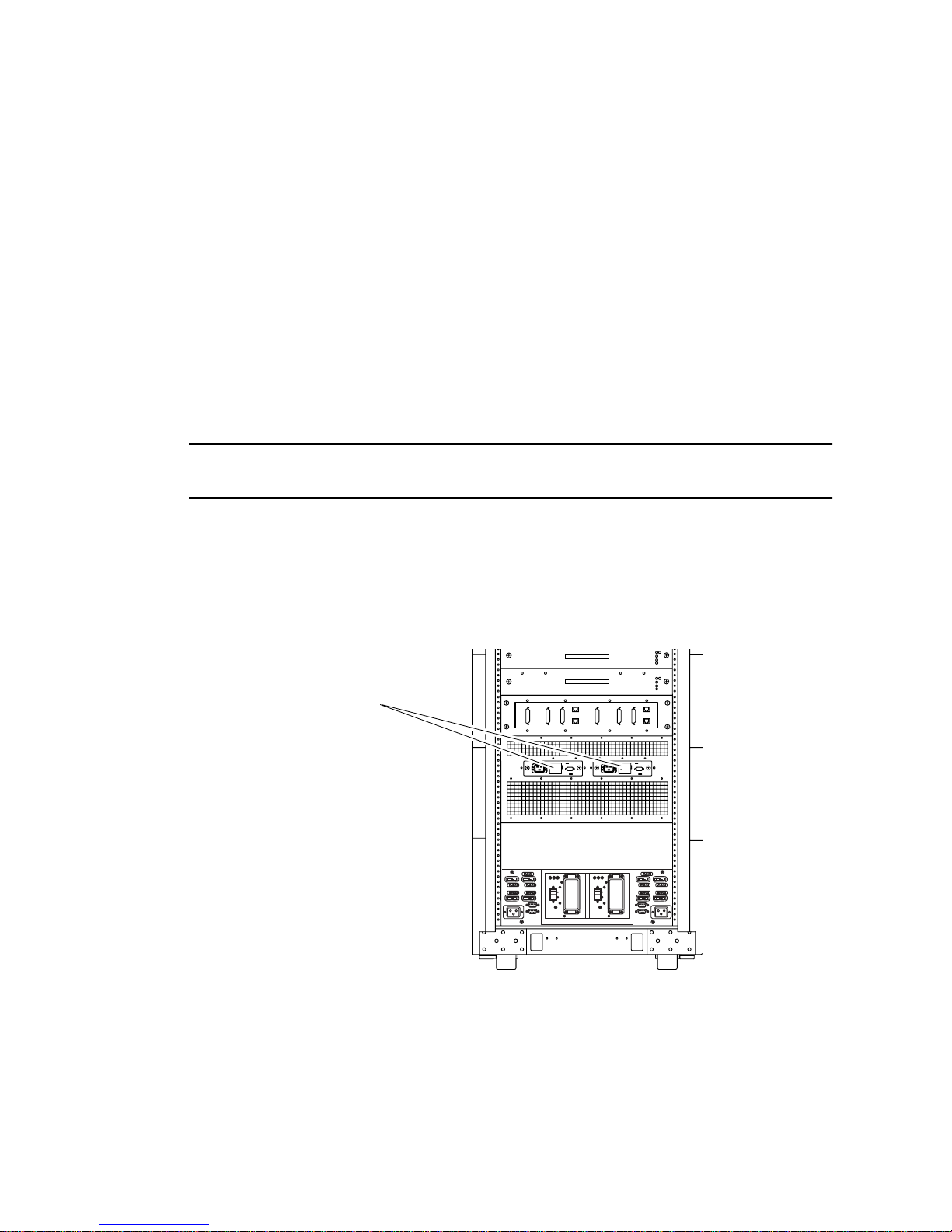
2. Press the switches that are located on the AC input boxes to the Off position.
AC input box
switches
2-2 Sun Fire E4900 and Sun Fire 6800/4800 Systems Power Supply and Fan Tray Upgrade Guide • June 2006
Page 7
2.1.3 Installing the EMI Gasket Kit
This kit contains the following:
■ Four 7.75-inch/200mm gaskets, plus a spare
■ One 5-inch/130mm gasket, plus a spare
■ Six ESD CPU/Memory board bags
Note – For systems with gaskets already installed, a second gasket should not be
installed.
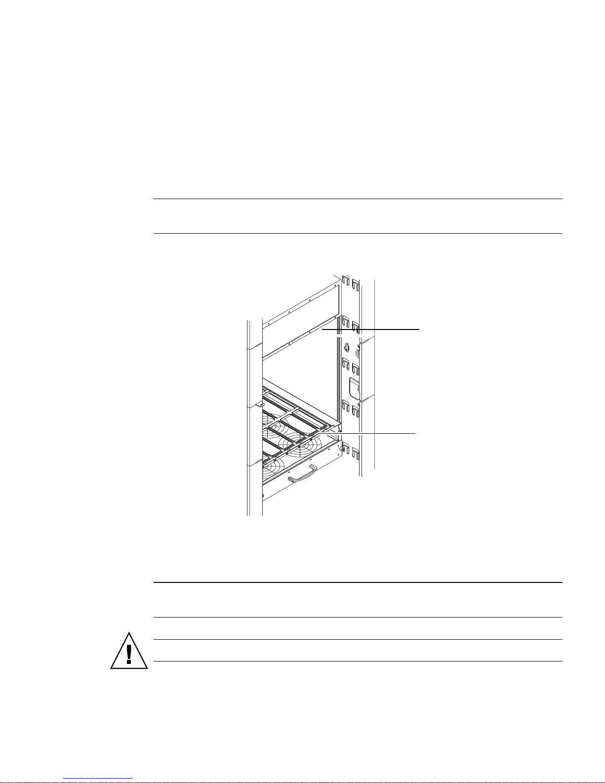
You will need a pair of needle-nosed pliers to guide the gaskets into the upper and
lower U-channels.
Upper U-channel
Lower U-channel
1. Remove all the CPU/Memory boards.
Refer to the Sun Fire 6800/4810/4800/3800 Systems Service Manual for the remove and
install instructions.
Note – Place each CPU/Memory board on one enclosed ESD CPU/Memory board
bag.
Caution – To avoid breakage, do not stack the CPU/Memory boards.
Chapter 2 Upgrading a Sun Fire 6800 System 2-3
Page 8
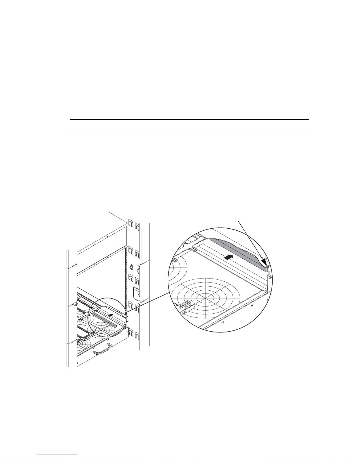
2. Remove the FT1 fan tray to access the area for the 5-inch gasket, located on the
underside of the chassis guide rail SB5.
Refer to the Sun Fire 6800/4810/4800/3800 Systems Service Manual for the remove and
install instructions.
2.1.3.1 Installing the 5-inch/130mm Foam Gasket
Note – Do not apply the gasket to the chassis side wall.
A 5-inch foam gasket is required on the underside of the chassis guide rail SB5.
1. Peel the entire tape off of the gasket.
2. Rotate the gasket so that the adhesive faces to the right.
3. Apply the gasket to the side of the guide rail frame, immediately below guide rail
SB5 (see figure below).
When properly installed, there will be no gaps above or in front of the gasket.
Gasket must touch this edge
2-4 Sun Fire E4900 and Sun Fire 6800/4800 Systems Power Supply and Fan Tray Upgrade Guide • June 2006
Page 9
2.1.3.2 Installing the Four 7.75-inch/200mm Foam Gaskets
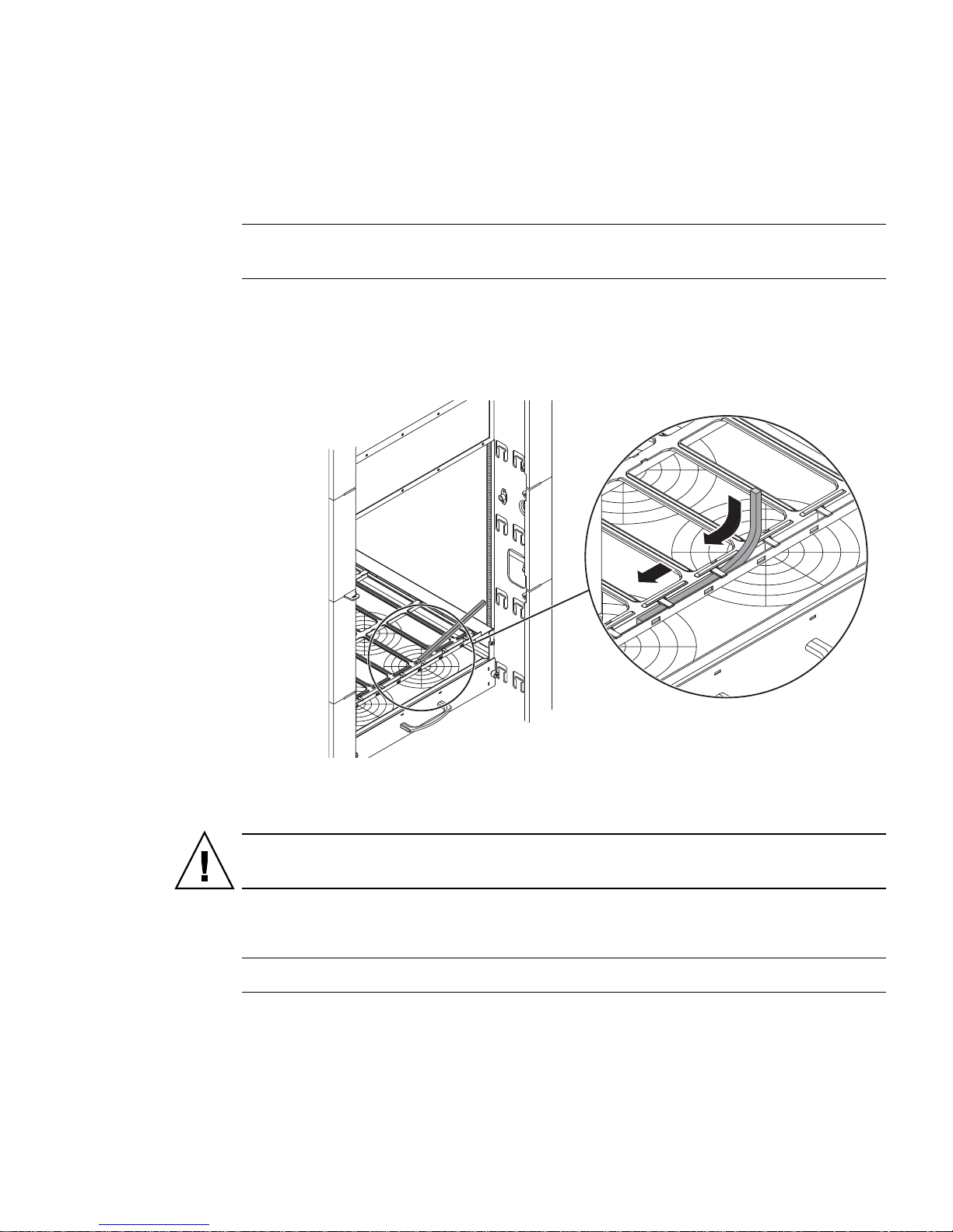
Two 7.75-inch foam gaskets must be installed in each U-channel.
Note – Do not remove the gasket adhesive strip prior to inserting the gasket into the
channel.
1. Insert a 7.75-inch gasket (adhesive side down) into the center of the lower Uchannel.
The gasket will be snug in the channel.
2. Using needle-nose pliers, carefully pull the gasket through the channel until it
reaches the end.
Caution – Be careful that the gasket does not snag in the channel. Excess force
could tear the gasket.
3. Repeat this procedure for the other half of the U-channel.
Note – There should be no visible gap between gaskets.
4. Once the gaskets are in place, lift the ends of each gasket and peel off 1/2 inch of
the tape and then firmly adhere the gasket into the channel.
Chapter 2 Upgrading a Sun Fire 6800 System 2-5
Page 10
5. Repeat steps 1-4 for the upper U-channel.
6. Reinstall the FT1 fan tray.
Refer to the Sun Fire 6800/4810/4800/3800 Systems Service Manual for the remove and
install instructions.
7. Reinstall all the CPU/Memory boards back into the system.
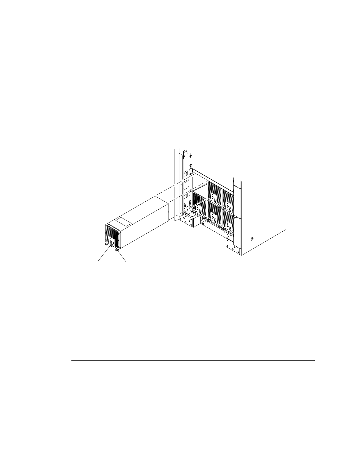
2.1.4 Replacing Power Supplies
Ejector
1. Attach a wrist or foot strap and connect the ESD strap to the system.
2. Loosen the two captive screws.
3. Unlock the ejector by pulling the ejector lever down.
4. Remove the power supply and set it aside.
5. Remove the protective cover from the new power supply connector, if applicable.
Captive screw
Note – Check the connector for any bent pins or damage. Also check the connector
on the system chassis backplane.
6. Pull the ejector lever down on the new power supply.
7. Insert the power supply into the slot and firmly seat it.
8. Push the ejector lever up to lock it into place.
2-6 Sun Fire E4900 and Sun Fire 6800/4800 Systems Power Supply and Fan Tray Upgrade Guide • June 2006
Page 11

9. Tighten the two captive screws of the power supply.
10. Repeat Steps 2-9 for the remaining power supplies.
Caution – Do not mix old and new power supplies.
2.1.5 Powering On the System
1. Press the switches that are located on the AC input boxes to the On position.
2. Power on the system.
Refer to the system administration manual for your product for complete step-bystep software commands.
2.2 Upgrading in a Powered-On System
Caution – A Sun Fire 6800 system EMI Gasket kit must be installed prior to
upgrading the UltraSPARC IV/IV+ CPU/Memory boards. The gasket kit cannot be
installed while the system is powered on. If the EMI gasket kit is not installed, see
section 2.1 Upgrading in a Powered-Off System.
2.2.1 Configuration Requirements
■ An EMI gasket kit must be installed. For systems with gaskets already installed, a
second gasket should not be installed.
■ For hardware, firmware, and OS minimum upgrade requirements, refer to the
applicable Sun Fire High-End and Midrange Systems CPU/Memory Board
Upgrade Requirements document at http://sun.com/documentation.
■ Upgrade power supplies before upgrading the UltraSPARC IV/IV+
CPU/Memory boards.
Chapter 2 Upgrading a Sun Fire 6800 System 2-7
Page 12
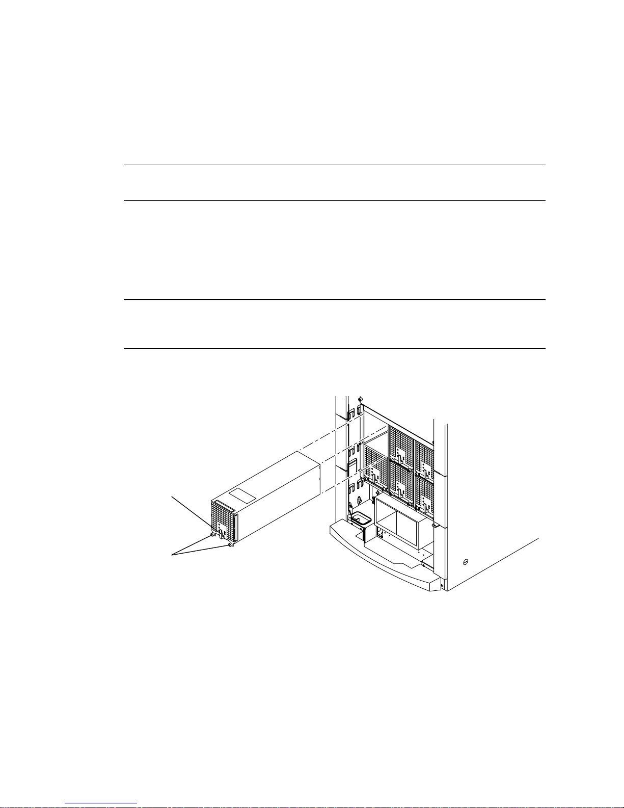
2.2.2 Replacing the Power Supplies
There are six power supplies in a Sun Fire 6800 System. Upgrade all power supplies
individually before installing the new UltraSPARC IV/IV+ CPU/Memory boards.
Note – Instructions for the removal and replacement of the power supplies can also
be found in your Sun Fire 6800/4810/4800/3800 Systems Service Manual.
1. Attach a wrist or foot strap and connect the ESD strap to the system.
2. Power off the appropriate power supply.
Refer to the platform administration manual for your system for complete
procedures to power off a power supply.
Note – When the green Activated LED on the power supply is off (not lit) and the
amber or blue OK to remove LED is on (lit), it is safe to continue. You DO NOT have
to power off the power grids, AC input box, or RTS module(s).
3. Loosen the two captive screws.
Ejector lever
Captive screws
4. Unlock the ejector lever by pulling the ejector down.
5. Remove the power supply and set it aside.
6. Remove the protective cover from the new power supply connector, if applicable.
2-8 Sun Fire E4900 and Sun Fire 6800/4800 Systems Power Supply and Fan Tray Upgrade Guide • June 2006
Page 13

Note – Check the connector for any bent pins or damage. Also check the connector
on the system chassis backplane.
7. Pull the ejector down on the new power supply.
8. Insert the power supply into the slot and firmly seat it.
9. Push the ejector up to lock it into place.
10. Tighten the two captive screws of the power supply.
11. Wait for the power supply to automatically power-on within 10 seconds.
Note – Make sure the green Activated LED is on (lit). If the green Activated LED is
not on, check to see if the power supply is seated properly.
12. Repeat Steps 2-11 for each of the remaining power supplies.
13. Reboot the system controller after all the new power supplies are installed.
Refer to the system administration manual for your product for complete step-bystep software commands.
Chapter 2 Upgrading a Sun Fire 6800 System 2-9
Page 14

2-10 Sun Fire E4900 and Sun Fire 6800/4800 Systems Power Supply and Fan Tray Upgrade Guide • June 2006
Page 15

CHAPTER
3
Upgrading a Sun Fire E4900 or Sun
Fire 4800 System
This kit contains the following:
■ Sun Fire E4900 Power supplies (3)
■ Sun Fire E4900 Fan trays (3)
■ Sun Fire 4800 EMI Gasket Kit
This chapter contains information on the following topics:
■ Section 3.1, “Upgrading in a Powered-Off System” on page 3-1
■ Section 3.2, “Upgrading in a Powered-On System” on page 3-9
3.1 Upgrading in a Powered-Off System
Upgrading the system requires:
1. Installing the EMI Gasket kit.
2. Upgrading the power supplies.
3. Upgrading the fan trays.
3-1
Page 16
3.1.1 Configuration Requirements
■ An EMI gasket kit must be installed. For systems with gaskets already installed, a
second gasket should not be installed.
■ Upgrade domains to a minimum supported version of firmware and Solaris
Operating System.
Refer to the applicable Sun Fire High-End and Midrange Systems CPU/Memory
Board Upgrade Requirements document at http://sun.com/documentation.
■ Upgrade power supplies and fan trays before upgrading the UltraSPARC IV/IV+
CPU/Memory boards.
3.1.2 Powering Off
1. Shut down the domains and power off the system.
Refer to the system administration manual for your product for complete step-bystep software commands.
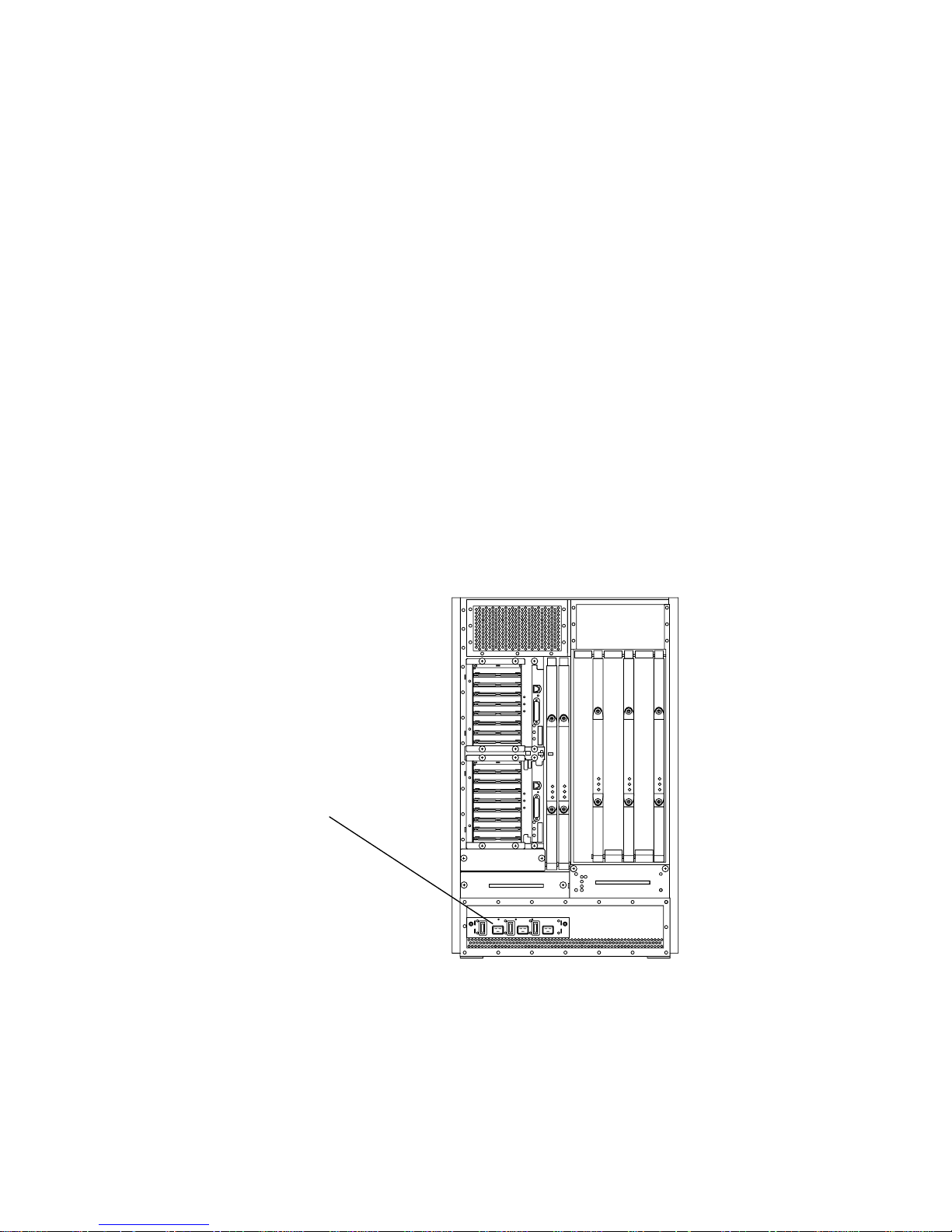
2. Press the three switches that are located on the AC input box to the Off position.
AC input box
3-2 Sun Fire E4900 and Sun Fire 6800/4800 Systems Power Supply and Fan Tray Upgrade Guide • June 2006
Page 17

3.1.3 Installing the EMI Gasket Kit
The gasket kit contains:
■ Two large (7.7 in./195 mm) EMI gaskets, plus a spare
■ Two small (2.6 in./66mm) EMI gaskets, plus a spare
■ Three ESD-safe CPU/Memory board bags
Note – For systems with gaskets already installed, a second gasket should not be
installed.
3.1.3.1 Installing the Large EMI Gaskets
Install the large (7.7 in./195 mm) gaskets in the upper and lower U-channels of the
cardcage.
1. Place a padded ESD-safe mat close to the system.
2. Wear an ESD strap and connect it to the system.
3. Remove all CPU/Memory boards and/or CPU/Memory filler panels.
Refer to the Sun Fire 6800/4810/4800/3800 Systems Service Manual or the Sun Fire
E6900/E4900 Systems Service Manual for the removal and installation instructions.
Note – Place each CPU/Memory board on one enclosed ESD-safe CPU/Memory
board bag.
Caution – To avoid breakage, do not stack the CPU/Memory boards.
4. Install one of the large gaskets in the lower U-channel.
a. Remove the protective tape from the gasket.
b. Insert the gasket (adhesive side down) into the lower U-channel.
Chapter 3 Upgrading a Sun Fire E4900 or Sun Fire 4800 System 3-3
Page 18
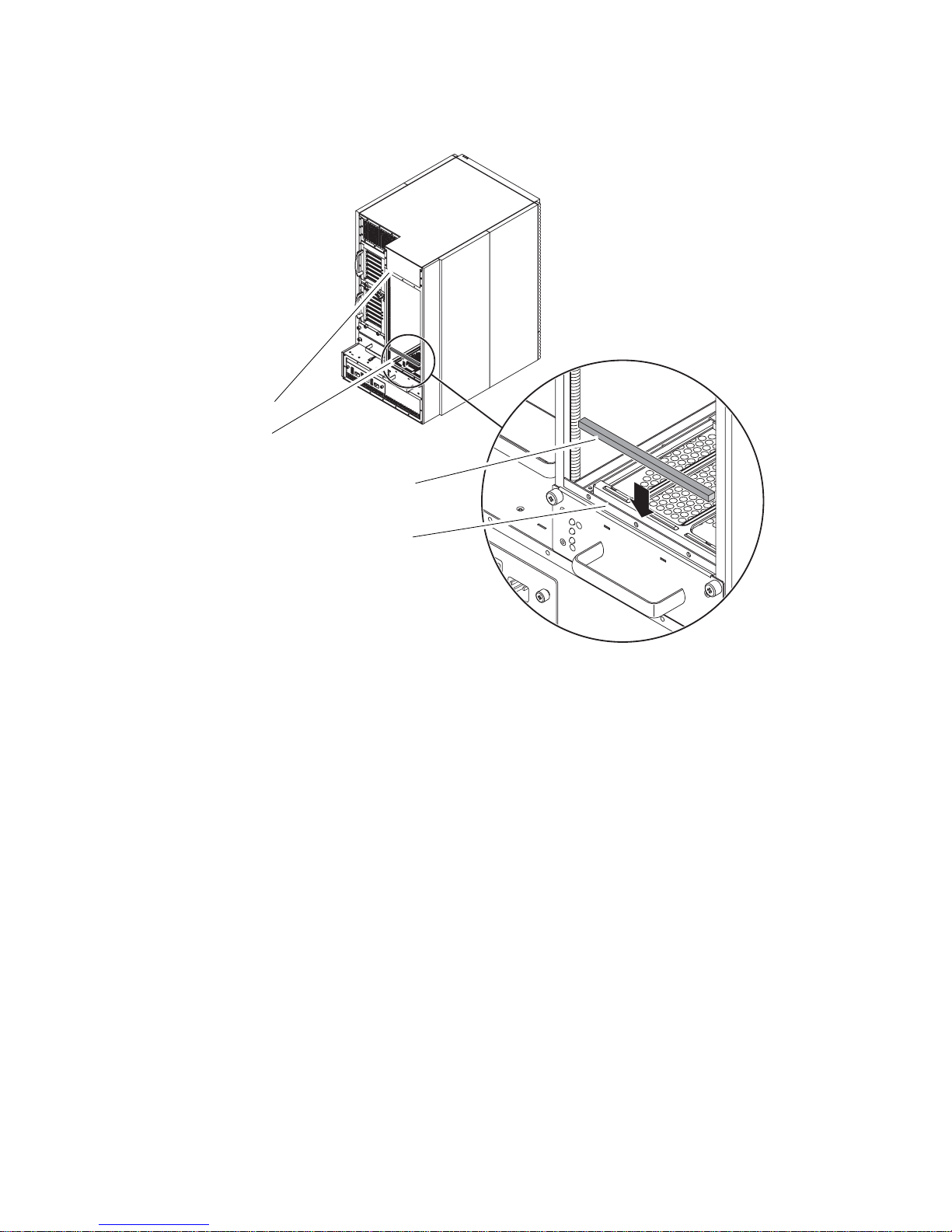
Upper U-channel
Lower U-channel
EMI Gasket
Lower U-channel (detail)
5. Install the other large gasket in the upper U-channel:
a. Remove the protective tape from the gasket.
b. Insert the gasket (adhesive side up) into the upper U-channel.
3.1.4 Replacing Power Supplies
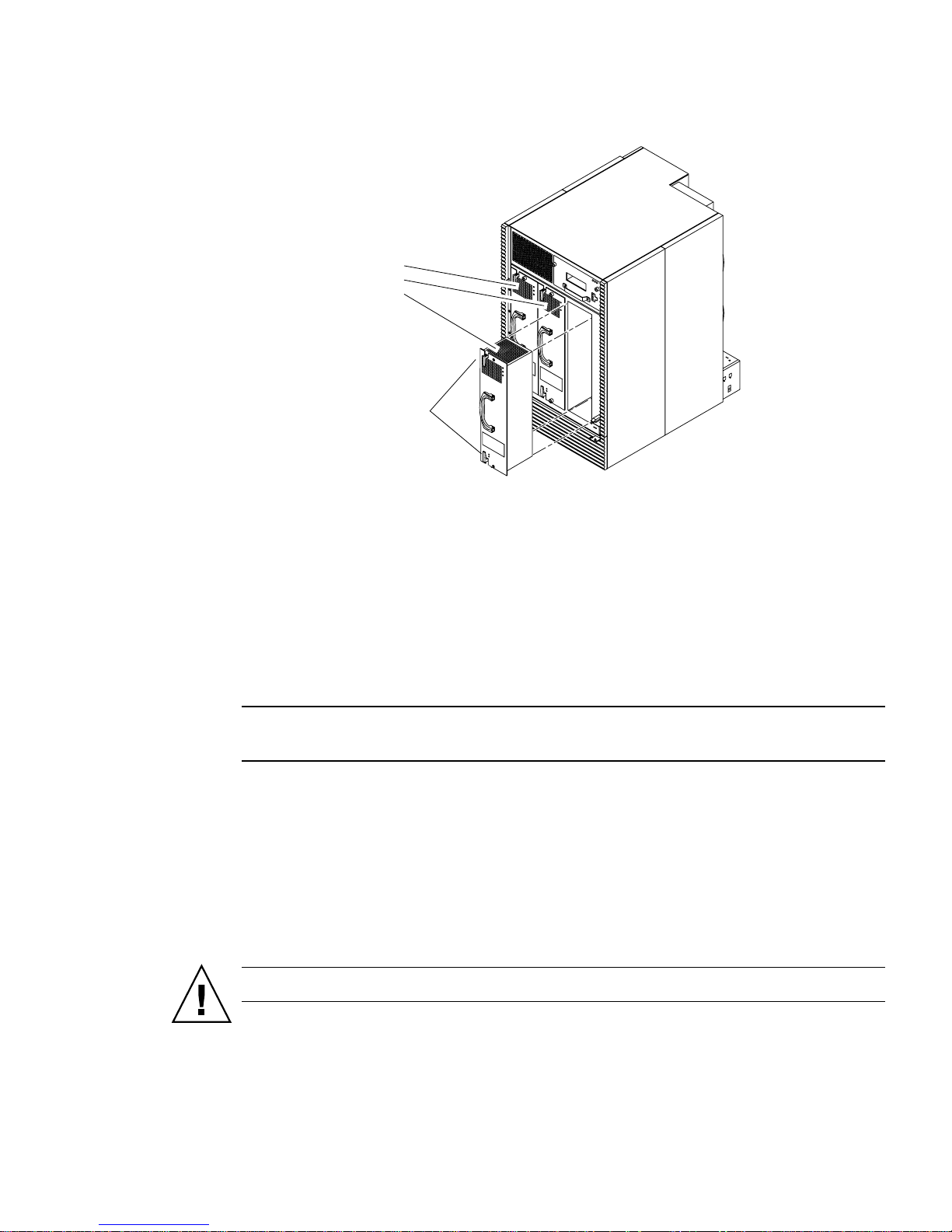
The Sun Fire E4900 and Sun Fire 4800 systems have three power supplies located in
the front—PS0, PS1, and PS2.
3-4 Sun Fire E4900 and Sun Fire 6800/4800 Systems Power Supply and Fan Tray Upgrade Guide • June 2006
Page 19
PS0
PS1
PS2
Ejectors
1. Attach a wrist or foot strap and connect the ESD strap to the system.
2. Loosen the two captive screws, located at the top and bottom of the power supply.
3. Unlock the ejectors by pulling the ejector levers outward.
4. Remove the power supply and set it aside.
5. Remove the protective cover from the new power supply connector, if applicable.
Note – Check the connector for any bent pins or damage. Also check the connector
on the system chassis backplane.
6. Pull the ejector levers outward on the new power supply.
7. Insert the power supply into the slot and firmly seat it.
8. Push both the levers inward to lock the power supply into place.
9. Tighten the two captive screws.
10. Repeat Steps 2-9 for each of the remaining power supplies.
Caution – Do not mix old and new power supplies.
Chapter 3 Upgrading a Sun Fire E4900 or Sun Fire 4800 System 3-5
Page 20
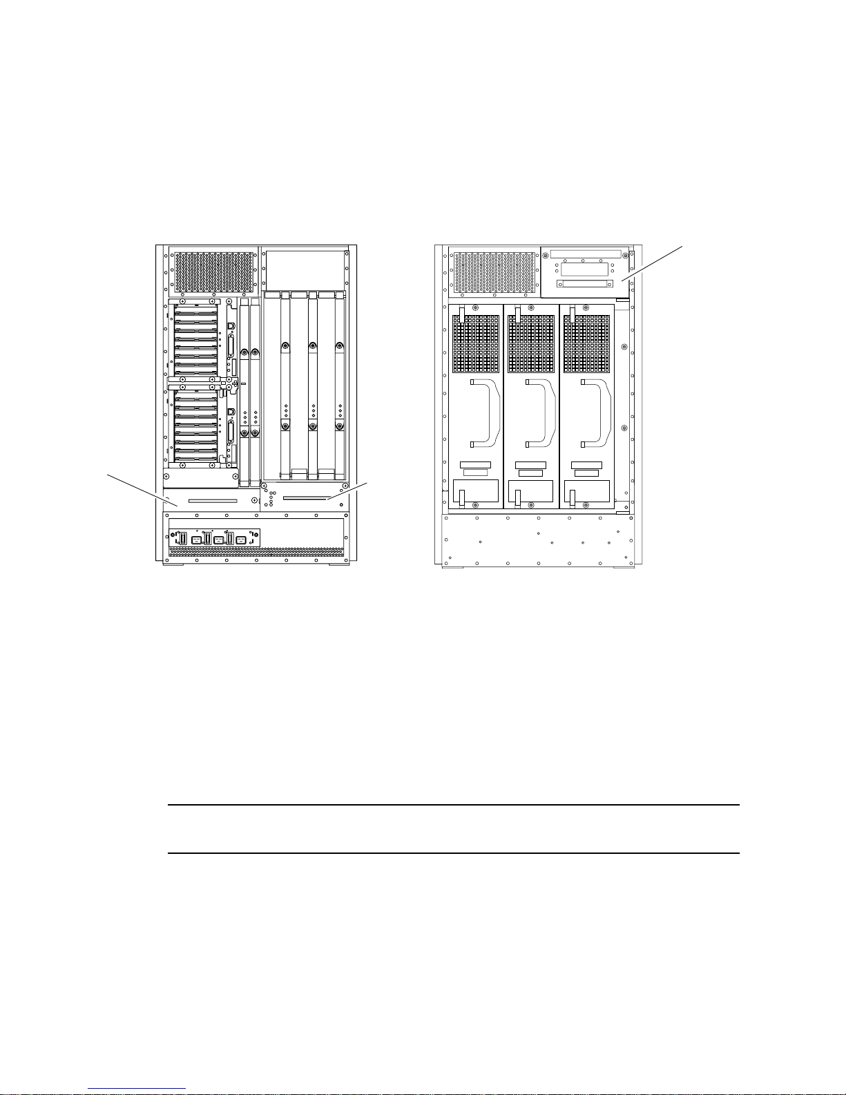
3.1.5 Replacing Fan Trays
The FT0 and FT2 fan trays are located in the rear of the system. FT1 is located in the
front.
FT1
FT0
FT2
Sun Fire E4900/4800 System–rear Sun Fire E4900/4800 System–front
1. Attach a wrist or foot strap and connect the ESD strap to the system.
2. Remove the front bezel on the FT1 fan tray by snapping it off.
FT0 and FT2 do not have bezels.
3. Loosen the captive screws on the fan tray.
4. Lift the fan tray out and set it aside.
5. Remove the protective cover from the fan tray connector, if applicable.
Note – Check the connector for any bent pins or damage. Also check the connector
on the system chassis backplane.
6. Slide the new fan tray into the slot.
7. Tighten the captive screws.
8. Replace the FT1 front bezel.
3-6 Sun Fire E4900 and Sun Fire 6800/4800 Systems Power Supply and Fan Tray Upgrade Guide • June 2006
Page 21
9. Repeat Steps 3-7 for the remaining fan trays.
Caution – Do not mix old and new fan trays.
3.1.5.1 Installing the Small EMI Gaskets
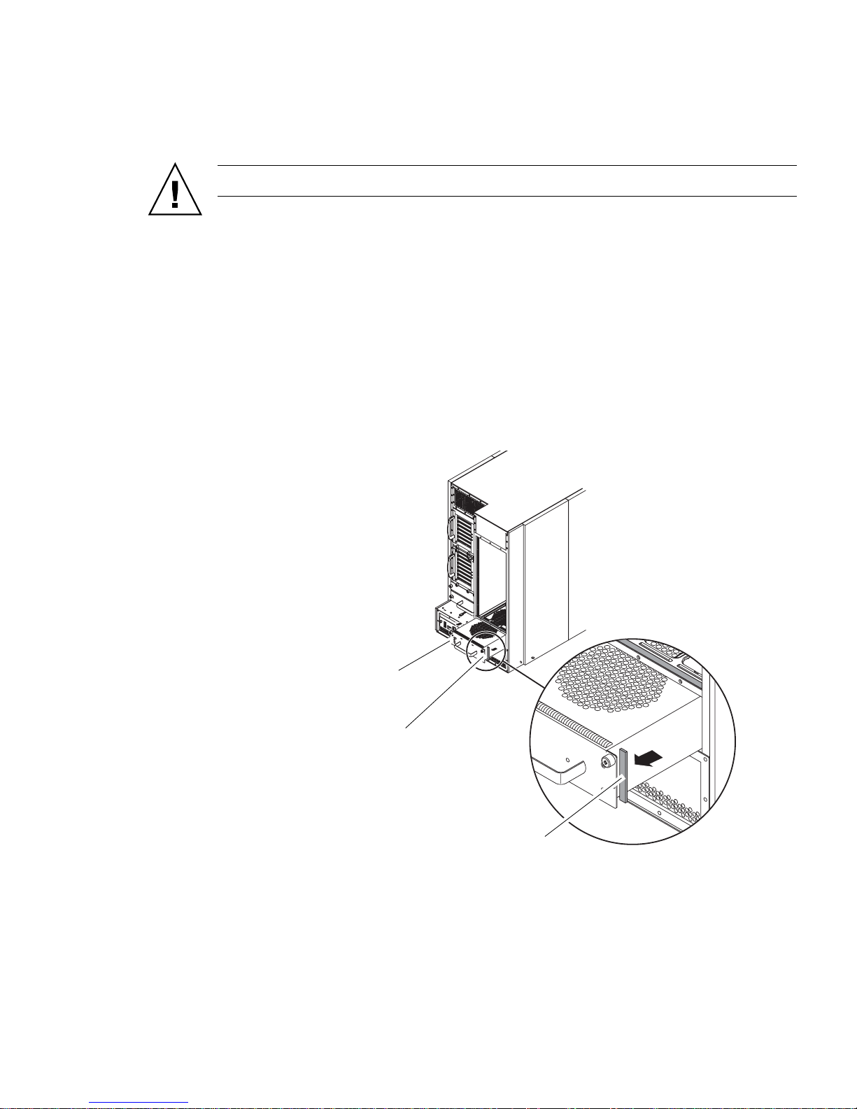
Check the new fan tray 2 (FT2) to see if EMI gaskets are already installed. If EMI
gaskets are installed, skip to section 3.1.6. If EMI gaskets are not installed on the fan
tray’s left and right flanges, install them now as shown below.
Install two small (2.6 in./66mm) EMI gaskets on fan tray FT2. (The FT1 and FT3 fan
trays do not require EMI gaskets.)
1. Loosen the captive screws on the front of fan tray FT2.
2. Pull the fan tray out partway.
Left mounting flange
Right mounting flange
EMI Gasket
3. Remove the protective tape from one of the small EMI gaskets.
4. Attach the gasket to the right mounting flange as follows:
Note that the gasket is to go on the back side of the flange. When the fan tray is in
place, the gasket should be between the fan tray flange and the cabinet chassis.
Chapter 3 Upgrading a Sun Fire E4900 or Sun Fire 4800 System 3-7
Page 22

a. Align the outer edge of the gasket with the edge of the flange.
The gasket should be between the edge of the flange and the captive screw.
b. Center the gasket vertically between the top and bottom of the flange, then
press into place.
5. Repeat Step 3 and Step 4 for the left mounting flange of the fan tray.
Slide the fan tray back into the system and tighten the captive screws.
3.1.6 Powering On
3.1.6.1 Deskside System
1. Press the three switches that are located on the AC input box to the On position.
2. Power on the system.
Refer to the system administration manual for your product for complete step-bystep software commands.
3.1.6.2 Sun Cabinet-Mounted System
1. Press the three switches that are located on the AC input box to the On position.
2. Make sure that the rack fan trays are switched on.
This switch is located in the back of the cabinet, below the power cord socket on
each rack fan tray.
3. Power on the system.
Refer to the system administration manual for your product for complete step-bystep software commands.
3-8 Sun Fire E4900 and Sun Fire 6800/4800 Systems Power Supply and Fan Tray Upgrade Guide • June 2006
Page 23

3.2 Upgrading in a Powered-On System
Caution – A Sun Fire 4800 EMI Gasket kit must be installed prior to upgrading the
UltraSPARC IV/IV+ CPU/Memory boards. The gasket kit cannot be installed while
the system is powered on. If the EMI gasket kit is not installed, see section 3.1
Upgrading in a Powered-Off System.
Upgrading the system requires:
1. Upgrading the power supplies.
2. Upgrading the fan trays.
3.2.1 Configuration Requirements
■ An EMI gasket kit must be installed. For systems with gaskets already installed, a
second gasket should not be installed.
■ Upgrade domains to a minimum supported version of firmware and Solaris
Operating System.
Refer to the applicable Sun Fire High-End and Midrange Systems CPU/Memory
Board Upgrade Requirements document at http://sun.com/documentation.
■ Upgrade power supplies and fan trays before upgrading the UltraSPARC IV/IV+
CPU/Memory boards.
3.2.2 Replacing the Power Supplies
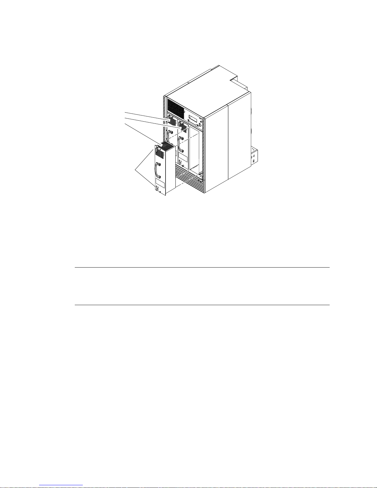
The Sun Fire E4900 System and the Sun Fire 4800 systems have three power supplies
located in the front. These power supplies are labeled PS0, PS1, and PS2.
Individually upgrade all power supplies and fan trays before installing the new
UltraSPARC IV/IV+ CPU/Memory boards.
Note – Instructions for the removal and replacement of the power supplies can also
be found in the Sun Fire E6900/E4900 Systems Service Manual or the Sun Fire
6800/4810/4800/3800 Systems Service Manual .
Chapter 3 Upgrading a Sun Fire E4900 or Sun Fire 4800 System 3-9
Page 24
PS0
PS1
PS2
Ejectors
1. Attach a wrist or foot strap and connect the ESD strap to the system.
2. Power off the appropriate power supply.
Refer to the platform administration manual for your system for complete
procedures to power off a power supply.
Note – When the green Activated LED on the power supply is off (not lit) and the
amber or blue OK to remove LED is on (lit), it is safe to continue. If your system is
mounted in a Sun Fire cabinet, you DO NOT have to power off the Redundant
Transfer Switch (RTS) module(s).
3. Loosen the two captive screws, located at the top and bottom of the power supply.
4. Unlock the ejectors by pulling the ejectors outward.
5. Remove the power supply and set it aside.
6. If your system is mounted in a Sun Fire cabinet, skip to Step 9.
3-10 Sun Fire E4900 and Sun Fire 6800/4800 Systems Power Supply and Fan Tray Upgrade Guide • June 2006
Page 25
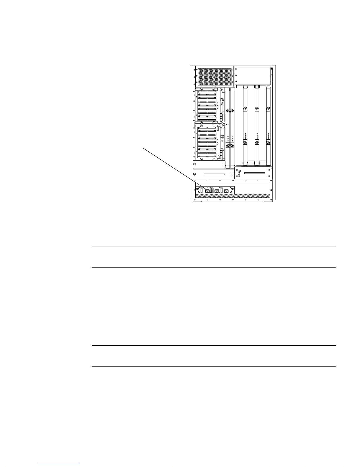
7. Press the corresponding switch located on the AC input box to the off position.
AC input box
8. Make sure that the corresponding switch on the AC input box for the new power
supply is turned on.
9. Remove the protective cover from the new power supply connector, if applicable.
Note – Check the connector for any bent pins or damage. Also check the connector
on the system chassis backplane.
10. Pull the ejector levers outward on the new power supply.
11. Insert the power supply into the slot and firmly seat it.
12. Push both the levers inward to lock the power supply into place.
13. Tighten the two captive screws.
14. Wait for the power supply to automatically power-on within 10 seconds.
Note – Make sure the green Activated LED is on (lit). If the green Activated LED is
not on, check to see if the power supply is seated properly.
15. Repeat 2-14 for each of the remaining power supplies.
Chapter 3 Upgrading a Sun Fire E4900 or Sun Fire 4800 System 3-11
Page 26
16. Reboot the system controller after all the new power supplies are installed.
Refer to the system administration manual for your product for complete step-bystep software commands.
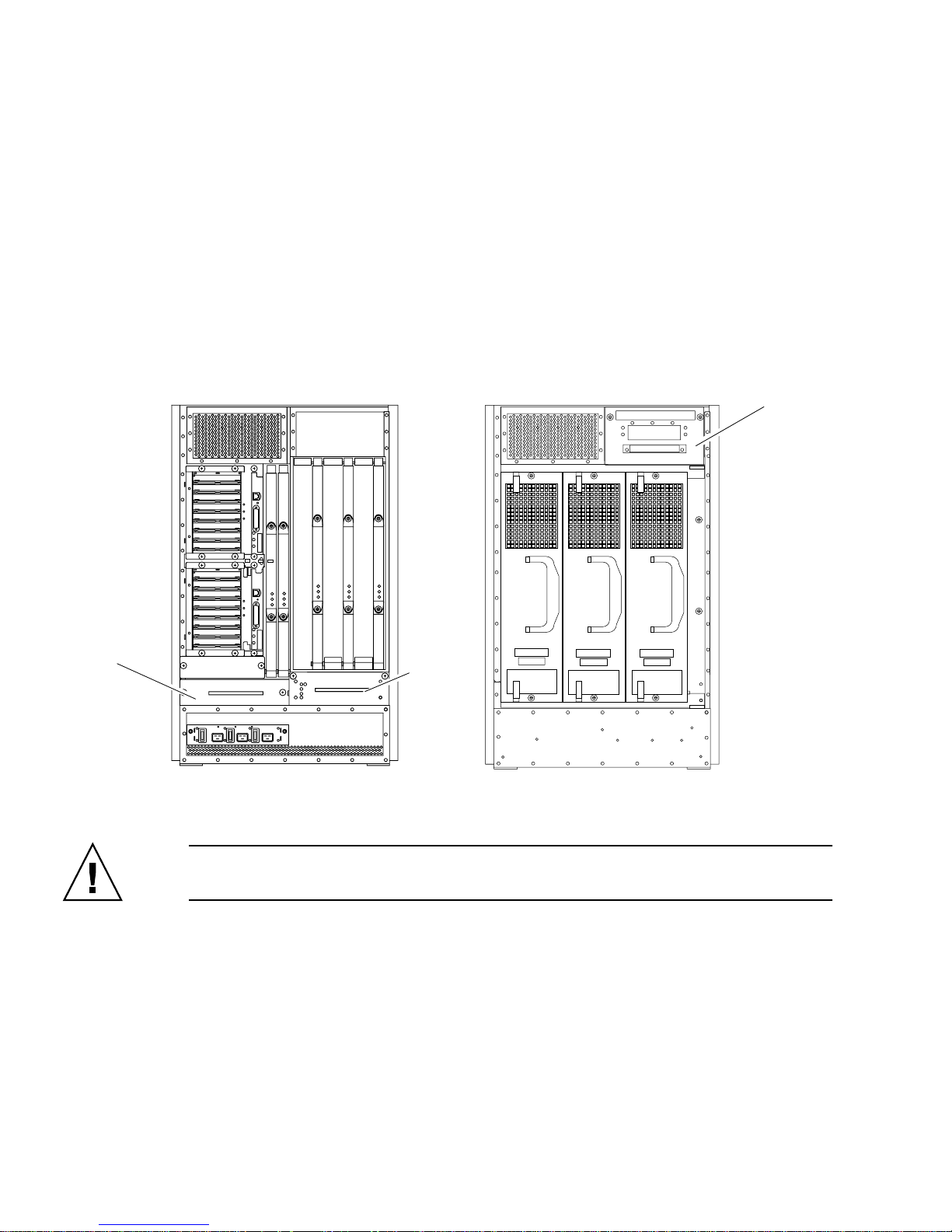
3.2.3 Replacing the Fan Trays
The FT0 and FT2 fan trays are located in the rear of the system. FT1 is located in the
front.
FT1
FT0
FT2
Sun Fire E4900/4800 System–rear Sun Fire E4900/4800 System–front
Caution – Within one minute of removing the fan tray, install the replacement fan
tray to prevent the system from overheating.
1. Attach a wrist or foot strap and connect the ESD strap to the system.
2. Power off the fan tray.
Refer to the Sun Fire Midrange Systems Platform Administration Manual for complete
procedures for powering off/on the fan tray.
3-12 Sun Fire E4900 and Sun Fire 6800/4800 Systems Power Supply and Fan Tray Upgrade Guide • June 2006
Page 27

Note – When the green Activated LED on the fan tray is off (not lit) and the amber
or blue OK to remove LED is on (lit), it is safe to continue.
3. When you replace the top fan tray, FT1, remove the front bezel by snapping it off.
4. Loosen the captive screws on the fan tray.
5. Slide the fan tray out and set it aside.
6. Remove the protective cover from the new fan tray connector, if applicable.
Note – Check the connector for any bent pins or damage. Also check the connector
on the system chassis backplane.
7. Slide the new fan tray into the slot.
8. Tighten the captive screws.
9. When you have installed the top fan tray, FT1, snap the front bezel back on.
10. Repeat Steps 2-8 for each of the remaining fan trays.
Caution – A Sun Fire 4800 EMI Gasket kit must be installed prior to upgrading the
UltraSPARC IV/IV+ CPU/Memory boards. The gasket kit cannot be installed while
the system is powered on. If the EMI gasket kit is not installed, see section 3.1
Upgrading in a Powered-Off System.
Chapter 3 Upgrading a Sun Fire E4900 or Sun Fire 4800 System 3-13
Page 28

Documentation, Support, and Training
Sun Function URL
Documentation http://www.sun.com/documentation/
Support http://www.sun.com/support/
Training http://www.sun.com/training/
Sun Welcomes Your Comments
Sun is interested in improving its documentation and welcomes your comments and
suggestions. You can submit your comments by going to:
http://www.sun.com/hwdocs/feedback
Please include the title and part number of your document with your feedback:
Sun Fire E4900 and Sun Fire 6800/4800 Systems Power Supply and Fan Tray Upgrade
Guide, part number 817-4818-14(v2)
3-14 Sun Fire E4900 and Sun Fire 6800/4800 Systems Power Supply and Fan Tray Upgrade Guide • June 2006
 Loading...