

Page 1

Sun Microsystems, Inc.
4150 Network Circle
Santa Clara, CA 95054 U.S.A.
650-960-1300
Send comments about this document to: [email protected]
Sun Fire
TM
B1600 Blade System
Chassis Switch Administration
Guide
Part No. 817-2576-10
June 2003, Revision A
Page 2

Copyright 2003Sun Microsystems, Inc.,4150 NetworkCircle, SantaClara, California95054, U.S.A. All rightsreserved.
Sun Microsystems, Inc.has intellectualproperty rightsrelating to technology embodied in the productthat isdescribed inthis document.In
particular,and withoutlimitation, theseintellectual property rightsmay includeone ormore of the U.S. patents listed at
http://www.sun.com/patents andone ormore additional patents or pending patent applications in the U.S. and in other countries.
This documentand theproduct to which it pertains are distributed under licenses restricting theiruse, copying,distribution, and
decompilation. Nopart ofthe product orof thisdocument maybe reproduced inany formby anymeans withoutprior writtenauthorization of
Sun andits licensors,if any.
Third-party software, including font technology, is copyrighted and licensed fromSun suppliers.
Parts ofthe product maybe derivedfrom BerkeleyBSD systems,licensed from the University of California. UNIX is a registered trademarkin
the U.S.and inother countries,exclusively licensedthrough X/Open Company, Ltd.
Sun, SunMicrosystems, the Sun logo, AnswerBook2, docs.sun.com, Sun Fire, and Solaris aretrademarks orregistered trademarks of Sun
Microsystems, Inc. in the U.S. and in other countries.
All SPARC trademarksare usedunder licenseand are trademarksor registered trademarksof SPARC International,Inc. inthe U.S.and inother
countries. Products bearingSPARC trademarksare based upon an architecturedeveloped bySun Microsystems, Inc.
The OPENLOOK andSun™ GraphicalUser Interfacewas developedby SunMicrosystems, Inc. for its users and licensees. Sun acknowledges
the pioneeringefforts of Xerox in researchingand developingthe conceptof visualor graphicaluser interfacesfor thecomputer industry. Sun
holds anon-exclusive licensefrom Xerox to the XeroxGraphical UserInterface, whichlicense alsocovers Sun’slicensees whoimplement OPEN
LOOK GUIsand otherwisecomply withSun’s writtenlicense agreements.
Use, duplication,or disclosure bythe U.S.Government issubject torestrictions set forthin theSun Microsystems, Inc.license agreements and as
provided in DFARS 227.7202-1(a) and 227.7202-3(a)(1995), DFARS 252.227-7013(c)(1)(ii)(Oct. 1998),FAR 12.212(a)(1995), FAR52.227-19, orFAR
52.227-14 (ALT III), as applicable.
DOCUMENTATION IS PROVIDED “AS IS” AND ALL EXPRESS OR IMPLIED CONDITIONS, REPRESENTATIONS AND WARRANTIES,
INCLUDING ANYIMPLIED WARRANTY OF MERCHANTABILITY,FITNESS FORA PARTICULAR PURPOSEOR NON-INFRINGEMENT,
ARE DISCLAIMED, EXCEPT TO THE EXTENT THAT SUCH DISCLAIMERS ARE HELD TO BE LEGALLY INVALID.
Copyright 2003Sun Microsystems, Inc.,4150 NetworkCircle, SantaClara, California95054, Etats-Unis. Tous droits réservés.
Sun Microsystems, Inc.a lesdroits depropriété intellectuels relatantsà latechnologie incorporéedans leproduit quiest décritdans ce
document. Enparticulier, et sansla limitation,ces droits de propriétéintellectuels peuventinclureun ouplus des brevetsaméricains énumérésà
http://www.sun.com/patents etun oules brevets plussupplémentaires ou les applications de brevet enattente dansles Etats-Uniset dansles
autres pays.
Ce produit oudocument estprotégé parun copyrightet distribué avec des licences qui en restreignent l’utilisation,la copie,la distribution,et la
décompilation. Aucunepartie dece produit oudocument nepeut être reproduite sousaucune forme,parquelque moyen que ce soit, sans
l’autorisation préalableet écritede Sunet deses bailleursde licence,s’il yena.
Le logicieldétenu pardes tiers,et quicomprend la technologie relative auxpolices decaractères, estprotégé parun copyrightet licenciépar des
fournisseurs deSun.
Des partiesde ceproduit pourront êtredérivées dessystèmes BerkeleyBSD licenciéspar l’Universitéde Californie.UNIX estune marque
déposée auxEtats-Unis etdans d’autres payset licenciéeexclusivement parX/Open Company, Ltd.
Sun, SunMicrosystems, le logo Sun, AnswerBook2, docs.sun.com, Sun Fire, et Solaris sont des marquesde fabriqueou desmarques déposées
de SunMicrosystems, Inc. aux Etats-Unis et dans d’autres pays.
Toutes lesmarques SPARCsont utiliséessous licenceet sontdes marquesde fabriqueou desmarques déposées de SPARCInternational, Inc.
aux Etats-Uniset dansd’autres pays. Les produits protantles marquesSPARC sont baséssur unearchitecture développée par Sun
Microsystems, Inc.
L’interfaced’utilisation graphiqueOPEN LOOKet Sun™a étédéveloppée parSun Microsystems, Inc.pour sesutilisateurs etlicenciés. Sun
reconnaît les efforts de pionniers de Xeroxpour larecherche et le développment du concept des interfaces d’utilisation visuelle ou graphique
pour l’industriede l’informatique.Sun détientune licensenon exclusivedo Xerox surl’interface d’utilisationgraphique Xerox, cettelicence
couvrant égalementles licenciées deSun quimettent en placel’interface d’utilisation graphiqueOPEN LOOK etqui enoutre se conformentaux
licences écritesde Sun.
LA DOCUMENTATION EST FOURNIE “EN L’ÉTAT” ET TOUTES AUTRES CONDITIONS, DECLARATIONS ET GARANTIES EXPRESSES
OU TACITES SONT FORMELLEMENT EXCLUES, DANS LA MESURE AUTORISEEPAR LALOI APPLICABLE,Y COMPRISNOTAMMENT
TOUTE GARANTIE IMPLICITE RELATIVE A LA QUALITE MARCHANDE, A L’APTITUDE A UNE UTILISATION PARTICULIERE OU A
L’ABSENCE DE CONTREFAÇON.
Page 3

Copyright (c) 2003 Sun Microsystems, Inc., 4150 Network Circle, Santa Clara, California 95054, U.S.A. All rights reserved. This product
protected by one or more U.S. Patents. Patents Pending.
This distribution may include materials developed by third parties.
Sun, Sun Microsystems, the Sun logo, Java, Solaris, Sun Fire and the 100% Pure Java logo are trademarks or registered trademarks of Sun
Microsystems, Inc. in the U.S. and other countries.
All SPARC trademarks are used under license and are trademarks or registered trademarks of SPARC International, Inc. in the U.S. and other
countries. Products bearing SPARC trademarks are based upon architecture developed by Sun Microsystems, Inc.
This productis covered and controlled by U.S. Export Control laws andmay be subject to theexport or importlaws in other countries. Nuclear,
missile, chemical biological weapons or nuclear maritime end uses or end users, whether direct or indirect, are strictly prohibited. Export or
reexport to countries subject to U.S. embargo or to entities identified on U.S. export exclusion lists, including, but not limited to, the denied
persons and specially designated nationals lists is strictly prohibited.
Use of any spare or replacement CPUs is limited to repair or one-for-one replacement of CPUs in products exported in compliance with U.S.
export laws. Use of CPUs as product upgrades unless authorized by the U.S. Government is strictly prohibited.
Copyright (c) 2003 Sun Microsystems, Inc., 4150 Network Circle, Santa Clara, California 95054, Etats-Unis. Tous droits réservés.Ce produit est
protégé par les brevets U.S. Brevets en cours.
Cette distribution peut comprendre des composants développés pardes tierces parties.
Sun, Sun Microsystems, le logo Sun, Java, Solaris, Sun Fire et le logo 100% Pure Java sont des marques de fabrique ou des marques déposées
de Sun Microsystems, Inc. aux Etats-Unis et dans d’autres pays.
Toutes les marques SPARC sont utilisées sous licence et sont des marques de fabrique ou des marques déposées de SPARC International, Inc.
aux Etats-Unis et dans d’autres pays. Les produits protant les marques SPARC sont basés sur une architecture développée par Sun
Microsystems, Inc.
Les produits qui font l’objet de ce manuel d’entretien et les informations qu’il contient sont régis par la législation américaine en matière de
contrôle des exportations et peuvent être soumis au droit d’autres pays dans le domaine des exportations et importations. Les utilisations
finales, ou utilisateurs finaux, pour des armes nucléaires, des missiles, des armes biologiques et chimiques ou du nucléaire maritime,
directement ou indirectement, sont strictement interdites. Les exportations ou réexportations vers des pays sous embargo des États-Unis, ou
vers des entités figurant sur les listes d’exclusion d’exportation américaines, y compris, mais de manière non exclusive, la liste de personnes
qui font objet d’un ordre de ne pas participer, d’une façon directe ou indirecte, aux exportations des produits ou des services qui sont régi par
la législation américaine en matière de contrôle des exportations (“U.S. Commerce Department’s Table of Denial Orders”) et la liste de
ressortissants spécifiquement désignés (“U.S. Treasury Department of Specially Designated Nationals and Blocked Persons”).
L’utilisation de pièces détachées ou d’unités centrales de remplacement est limitée aux réparations ou à l’change standard d’unités centrales
pour les produits exportés, conformément à la législation américaine en matière d’exportation. Sauf autorisation par les autorités des ÉtatsUnis, l’utilisation d’unités centrales pour procéder à des mises à jour de produits est rigoureusement interdite.
Page 4

Page 5

v
Contents
1. Introduction 1-1
1.1 Overview 1-2
1.1.1 Switch Architecture 1-2
1.1.2 Ways of Accessing the Switch Management Application 1-2
1.2 Description of Hardware 1-3
1.2.1 Ethernet Ports 1-3
1.2.1.1 Up-link Ports 1-3
1.2.1.2 Internal Ports 1-4
1.2.2 Status LEDs 1-5
1.3 Features of the Switch 1-6
1.4 Switch Default Settings 1-9
2. Initial Configuration 2-1
2.1 Connecting to the Switch Interface 2-2
2.1.1 Configuration Options 2-2
2.1.1.1 Configuring the Switch Through the Built-in Switch
Interfaces 2-2
2.2 Enabling SNMP Management Access 2-3
2.2.1 Community Strings 2-3
2.2.2 Trap Receivers 2-4
Page 6

vi Sun Fire B1600 Blade System Chassis Switch Administration Guide • June 2003
3. General Management of the Switch 3-1
3.1 Using the Web Interface 3-2
3.1.1 Navigating the Web Browser Interface 3-3
3.1.1.1 Home Page 3-3
3.1.1.2 Configuration Options 3-4
3.1.2 Panel Display 3-4
3.1.3 Main Menu 3-5
3.2 Basic Configuration 3-8
3.2.1 Displaying System Information 3-8
3.2.1.1 Web Interface: Displaying and Specifying Identification
Details 3-8
3.2.1.2 Command-line Interface: Displaying and Specifying
Identification Details 3-10
3.2.1.3 MIB Variables: Identification Details 3-11
3.2.2 Setting the IP Address 3-12
3.2.2.1 Manual Configuration 3-13
3.2.2.2 Using DHCP/BOOTP 3-16
3.2.3 Displaying Switch Software Versions 3-18
3.2.3.1 Web Interface: Displaying Switch Software Version
Information 3-18
3.2.3.2 Comand-line Interface: Displaying Switch Software
Version Information 3-19
3.2.3.3 MIB Variables Associated With Software Version
Information 3-20
3.2.4 Managing Firmware 3-21
3.2.4.1 Downloading Switch Firmware From a Server 3-21
3.2.5 Saving or Restoring Configuration Settings 3-25
3.2.5.1 Downloading Configuration Settings From a Server
3-25
3.2.6 Configuring User Authentication 3-28
3.2.6.1 Web Interface: Configuring User Authentication 3-30
Page 7

Contents vii
3.2.6.2 Command-line Interface: Configuring User
Authentication 3-32
3.2.6.3 MIB variables Associated With User Authentication
3-33
3.2.7 Configuring SNMP 3-33
3.2.7.1 Configuring SNMP Access 3-34
3.2.7.2 Specifying Trap Managers and Trap Types 3-36
3.3 Configuring Global Network Protocols 3-39
3.3.1 VLAN Configuration 3-39
3.3.1.1 Displaying Basic VLAN Information 3-41
3.3.1.2 Enabling or Disabling GVRP (Global Setting) 3-45
3.3.1.3 Configuring VLANs 3-46
3.3.1.4 Adding Static Members to VLANs 3-50
3.3.2 Multicast Configuration 3-54
3.3.2.1 Configuring IGMP Snooping Parameters 3-55
3.3.2.2 Specifying Interfaces Connected to Multicast Routers
3-59
3.3.2.3 Configuring Multicast Services 3-64
3.3.3 Broadcast Storm Control (Global Setting) 3-67
3.3.3.1 Web Interface: Using Broadcast Storm Control 3-67
3.3.3.2 Command-line Interface: Using Broadcast Storm
Control 3-68
3.3.4 Spanning Tree Algorithm Configuration 3-70
3.3.4.1 Configuring Basic STA Settings 3-70
3.3.4.2 Configuring Advanced STA Settings 3-76
3.3.5 Class of Service Configuration 3-78
3.3.5.1 Setting the Default Priority for Interfaces 3-78
3.3.5.2 Mapping COS Values to Egress Queues 3-80
3.3.5.3 Setting the Service Weight for Traffic Classes 3-84
3.3.5.4 Mapping Layer 3/4 Priorities to COS Values 3-85
Page 8

viii Sun Fire B1600 Blade System Chassis Switch Administration Guide • June 2003
3.3.5.5 Mapping IP Precedence 3-87
3.3.5.6 Mapping DSCP Priority 3-90
3.3.6 Address Table Settings 3-92
3.3.6.1 Displaying the Address Table 3-92
3.3.6.2 Changing the Aging Time 3-94
3.4 Port Configuration 3-96
3.4.1 Displaying Connection Status 3-96
3.4.2 Configuring Interface Connections 3-102
3.4.2.1 Web Interface: Configuring Interface Connections
3-103
3.4.2.2 Command-line Interface: Configuring Interface
Connections 3-105
3.4.2.3 MIB Variables Inspecting or Configuring Interface
Connections 3-105
3.4.3 Configuring Aggregated Links 3-107
3.4.3.1 Dynamically Configuring an Aggregated Link with
LACP 3-108
3.4.3.2 Statically Configuring an Aggregated Link 3-111
3.4.4 Configuring VLAN Behavior for Interfaces 3-114
3.4.4.1 Web Interface: Configuring VLAN Behavior for
Interfaces 3-115
3.4.4.2 Command-line Interface: Configuring VLAN Behavior
for Interfaces 3-117
3.4.4.3 MIB Variables Associated With VLAN Behavior of
Interfaces 3-118
3.4.5 Configuring Static Addresses 3-121
3.4.5.1 Web Interface: Configuring Static Addresses 3-122
3.4.5.2 Command-line Interface: Configuring Static
Addresses 3-123
3.4.5.3 MIB Variables Associated With Static Addresses 3-123
3.4.6 Managing Interfaces for Spanning Tree Algorithm 3-125
Page 9

Contents ix
3.4.6.1 Displaying the Current Interface Settings for STA
3-125
3.4.6.2 Configuring Interface Settings for STA 3-129
3.4.6.3 Checking the STA Protocol Status for Interfaces 3-132
3.4.7 Filtering Traffic From the Down Link Ports to the Management
Port 3-134
3.4.7.1 Web Interface: Filtering Traffic to the Management
Port 3-135
3.4.7.2 Command-line Interface: Filtering Traffic to the
Management Port 3-136
3.4.7.3 MIB Variables Associated With Filtering Traffic to the
Management Port 3-137
3.5 Monitoring Port and Management Traffic 3-139
3.5.1 Configuring Port Mirroring 3-139
3.5.1.1 Web Interface: Configuring Port Mirroring 3-139
3.5.1.2 Command-line Interface: Configuring Port Mirroring
3-140
3.5.1.3 MIB Variables Associated With Port Mirroring 3-141
3.5.2 Showing Port Statistics 3-141
3.5.2.1 Web Interface: Viewing Port Statistics 3-145
3.5.2.2 Command-line Interface: Viewing Port Statistics 3-147
3.5.2.3 MIB Variables Associated With Port Statistics 3-148
3.5.3 Showing SNMP Statistics 3-152
3.5.3.1 Web Interface: Viewing SNMP Statistics 3-153
3.5.3.2 Command-line Interface: Viewing SNMP Statistics
3-155
3.5.3.3 MIB Variables Associated With SNMP Statistics 3-156
3.5.4 Configuring Message Logs 3-156
3.5.4.1 Web Interface: Configuring Message Logs 3-157
3.5.4.2 Command-line Interface: Configuring Message Logs
3-158
Page 10

x Sun Fire B1600 Blade System Chassis Switch Administration Guide • June 2003
3.5.4.3 MIB Variables Associated With Message Logs 3-159
4. Command-Line Reference 4-1
4.1 Using the Command-Line Interface 4-2
4.1.1 Accessing the CLI 4-2
4.1.1.1 Console Connection 4-2
4.1.1.2 Telnet Connection 4-3
4.1.2 Entering Commands 4-4
4.1.2.1 Keywords and Arguments 4-4
4.1.2.2 Minimum Abbreviation 4-5
4.1.2.3 Command Completion 4-5
4.1.2.4 Getting Help on Commands 4-5
4.1.2.5 Showing Commands 4-6
4.1.2.6 Partial Keyword Lookup 4-7
4.1.2.7 Negating the Effect of Commands 4-7
4.1.2.8 Using Command History 4-7
4.1.2.9 Understanding Command Modes 4-7
4.1.2.10 Exec Commands 4-8
4.1.2.11 Configuration Commands 4-9
4.1.2.12 Command-Line Processing 4-10
4.2 Command Groups 4-11
4.3 Detailed Command Description 4-13
4.3.1 General Commands 4-13
4.3.1.1 enable 4-13
4.3.1.2 disable 4-14
4.3.1.3 configure 4-15
4.3.1.4 show history 4-16
4.3.1.5 reload 4-17
4.3.1.6 end 4-18
Page 11

Contents xi
4.3.1.7 exit 4-19
4.3.1.8 quit 4-19
4.3.2 Flash/File Commands 4-20
4.3.2.1 copy 4-20
4.3.2.2 delete 4-22
4.3.2.3 dir 4-23
4.3.2.4 whichboot 4-25
4.3.2.5 boot system 4-26
4.3.3 System Management Commands 4-27
4.3.3.1 hostname 4-28
4.3.3.2 username 4-29
4.3.3.3 enable password 4-30
4.3.3.4 ip http port 4-31
4.3.3.5 ip http server 4-32
4.3.3.6 jumbo frame 4-33
4.3.3.7 logging on 4-34
4.3.3.8 logging history 4-35
4.3.3.9 clear logging 4-36
4.3.3.10 show logging 4-37
4.3.3.11 show startup-config 4-38
4.3.3.12 show running-config 4-40
4.3.3.13 show system 4-42
4.3.3.14 show users 4-44
4.3.3.15 show version 4-44
4.3.4 Authentication Commands 4-45
4.3.4.1 authentication login 4-46
4.3.4.2 radius-server host 4-48
4.3.4.3 radius-server port 4-48
Page 12

xii Sun Fire B1600 Blade System Chassis Switch Administration Guide • June 2003
4.3.4.4 radius-server key 4-49
4.3.4.5 radius-server retransmit 4-50
4.3.4.6 radius-server timeout 4-50
4.3.4.7 show radius-server 4-51
4.3.4.8 tacacs-server host 4-52
4.3.4.9 tacacs-server port 4-52
4.3.4.10 tacacs-server key 4-53
4.3.4.11 show tacacs-server 4-54
4.3.5 SNMP Commands 4-54
4.3.5.1 snmp-server community 4-55
4.3.5.2 snmp-server contact 4-56
4.3.5.3 snmp-server location 4-57
4.3.5.4 snmp-server host 4-57
4.3.5.5 snmp-server enable traps 4-59
4.3.5.6 show snmp 4-60
4.3.6 Line Commands 4-62
4.3.6.1 line 4-62
4.3.6.2 login 4-63
4.3.6.3 password 4-64
4.3.6.4 exec-timeout 4-66
4.3.6.5 password-thresh 4-66
4.3.6.6 silent-time 4-67
4.3.6.7 show line 4-68
4.3.7 IP Commands 4-69
4.3.7.1 ip address 4-70
4.3.7.2 ip dhcp restart 4-71
4.3.7.3 ip dhcp client-identifier 4-72
4.3.7.4 ip default-gateway 4-74
Page 13

Contents xiii
4.3.7.5 show ip interface 4-75
4.3.7.6 show ip redirects 4-75
4.3.7.7 ping 4-76
4.3.7.8 ip filter 4-77
4.3.7.9 show ip filter 4-81
4.3.8 Interface Commands 4-83
4.3.8.1 interface 4-83
4.3.8.2 description 4-84
4.3.8.3 speed-duplex 4-85
4.3.8.4 negotiation 4-86
4.3.8.5 capabilities 4-87
4.3.8.6 flowcontrol 4-89
4.3.8.7 shutdown 4-91
4.3.8.8 switchport broadcast packet-rate 4-91
4.3.8.9 clear counters 4-93
4.3.8.10 show interfaces status 4-93
4.3.8.11 show interfaces counters 4-95
4.3.8.12 show interfaces switchport 4-96
4.3.9 Address Table Commands 4-98
4.3.9.1 mac-address-table static 4-99
4.3.9.2 clear mac-address-table dynamic 4-100
4.3.9.3 show mac-address-table 4-100
4.3.9.4 mac-address-table aging-time 4-101
4.3.9.5 show mac-address-table aging-time 4-102
4.3.10 Port Security Commands 4-103
4.3.10.1 port security 4-103
4.3.11 Spanning Tree Commands 4-105
4.3.11.1 spanning-tree 4-105
Page 14

xiv Sun Fire B1600 Blade System Chassis Switch Administration Guide • June 2003
4.3.11.2 spanning-tree mode 4-106
4.3.11.3 spanning-tree forward-time 4-107
4.3.11.4 spanning-tree hello-time 4-108
4.3.11.5 spanning-tree max-age 4-109
4.3.11.6 spanning-tree priority 4-110
4.3.11.7 spanning-tree pathcost method 4-111
4.3.11.8 spanning-tree transmission-limit 4-112
4.3.11.9 spanning-tree cost 4-112
4.3.11.10 spanning-tree port-priority 4-114
4.3.11.11 spanning-tree edge-port 4-115
4.3.11.12 spanning-tree protocol-migration 4-116
4.3.11.13 spanning-tree link-type 4-117
4.3.11.14 show spanning-tree 4-118
4.3.12 VLAN Commands 4-120
4.3.12.1 vlan database 4-121
4.3.12.2 vlan 4-121
4.3.12.3 interface vlan 4-123
4.3.12.4 switchport mode 4-123
4.3.12.5 switchport acceptable-frame-types 4-124
4.3.12.6 switchport ingress-filtering 4-125
4.3.12.7 switchport native vlan 4-126
4.3.12.8 switchport allowed vlan 4-127
4.3.12.9 switchport forbidden vlan 4-129
4.3.12.10 show vlan 4-130
4.3.13 GVRP and Bridge Extension Commands 4-131
4.3.13.1 switchport gvrp 4-132
4.3.13.2 show gvrp configuration 4-132
4.3.13.3 garp timer 4-133
Page 15

Contents xv
4.3.13.4 show garp timer 4-135
4.3.13.5 bridge-ext gvrp 4-135
4.3.13.6 show bridge-ext 4-136
4.3.14 IGMP Snooping Commands 4-138
4.3.14.1 ip igmp snooping 4-139
4.3.14.2 ip igmp snooping vlan static 4-140
4.3.14.3 ip igmp snooping version 4-141
4.3.14.4 show ip igmp snooping 4-142
4.3.14.5 show mac-address-table multicast 4-143
4.3.14.6 ip igmp snooping querier 4-144
4.3.14.7 ip igmp snooping query-count 4-144
4.3.14.8 ip igmp snooping query-interval 4-145
4.3.14.9 ip igmp snooping query-max-response-time 4-146
4.3.14.10 ip igmp snooping router-port-expire-time 4-147
4.3.14.11 ip igmp snooping vlan mrouter 4-148
4.3.14.12 show ip igmp snooping mrouter 4-149
4.3.15 Priority Commands 4-150
4.3.15.1 switchport priority default 4-151
4.3.15.2 queue bandwidth 4-152
4.3.15.3 queue cos-map 4-153
4.3.15.4 show queue bandwidth 4-155
4.3.15.5 show queue cos-map 4-156
4.3.15.6 map ip precedence (Global Configuration) 4-157
4.3.15.7 map ip precedence (Interface Configuration) 4-158
4.3.15.8 map ip dscp (Global Configuration) 4-159
4.3.15.9 map ip dscp (Interface Configuration) 4-160
4.3.15.10 show map ip precedence 4-161
4.3.15.11 show map ip dscp 4-162
Page 16

xvi Sun Fire B1600 Blade System Chassis Switch Administration Guide • June 2003
4.3.16 Mirror Port Commands 4-164
4.3.16.1 port monitor 4-164
4.3.16.2 show port monitor 4-165
4.3.17 Link Aggregation Commands 4-166
4.3.17.1 channel-group 4-167
4.3.17.2 lacp 4-168
A. Management Information Base A-1
A.1 Supported MIBs A-2
A.2 Supported Traps A-3
B. Troubleshooting B-1
B.1 Diagnosing Switch Indicators B-2
B.2 Diagnosing Port Connections B-2
B.3 Accessing the Management Interface B-2
B.4 Using System Logs B-4
B.4.1 Log Messages B-4
B.5 Error Messages B-5
B.5.1 Command-Line Error Detection B-5
B.5.2 System Errors B-6
B.5.3 Command Line Errors B-6
B.5.4 Web Interface Errors B-9
C. Specifications C-1
C.1 Switch Architecture C-2
C.2 Management Features C-3
C.3 Physical C-3
C.4 Power C-4
C.5 Environmental C-4
C.6 Standards C-4
Page 17

Contents xvii
Glossary Glossary-1
Index Index-1
Page 18

xviii Sun Fire B1600 Blade System Chassis Switch Administration Guide • June 2003
Page 19

xix
Preface
This Sun Fire B1600 Blade System Chassis Switch Administration Guide provides
information that enables you to understand and use the switch inside the Switch and
System Controller (SSC) module in the system chassis. There are two interfaces to
the switch: a command-line interface and a web interface. This manual describes
both.
The manual is intended for network administrators who are responsible for
managing the system chassis. The manual assumes a working knowledge of local area
network operations and familiarity with networking protocols.
Before You Read This Book
Before you start configuring the switch:
Install your system chassis by following the instructions in the Sun Fire B1600 Blade
System Chassis Hardware Installation Guide and the Sun Fire B1600 Blade System Chassis
Software Setup Guide.
How This Book Is Organized
Chapter 1 provides an overview of the switch, including management options,
hardware features, switching features, and default settings.
Chapter 2 describes how to connect to the switch console and to the alternative web
interface.
Page 20

xx Sun Fire B1600 Blade System Chassis Switch Administration Guide • June 2003
Chapter 3 describes all of the key switch features and shows you how to configure
these features through both the web interface and the console interface. It also
provides a list of comparable MIB variables used by SNMP management
applications.
Chapter 4 provides a detailed listing of all the console interface commands and
parameters.
Appendix A lists the Management Information Bases (MIB) and traps supported by
this switch.
Appendix B provides basic troubleshooting information, including how to interpret
the system and port LEDs, how to solve problems that might prevent you from
accessing the management interface, and how to use the system logs.
Appendix C provides detailed specifications of the switch’s features.
The Glossary is a list of words and phrases and their definitions.
The Index provides page references to all of the key topics discussed in this manual.
Page 21

Preface xxi
Typographic Conventions
Related Documentation
Accessing Sun Documentation
You can view, print, or purchase a broad selection of Sun documentation, including
localized versions, at:
http://www.sun.com/documentation
Typeface Meaning Examples
AaBbCc123 The names of commands and
files; on-screen computer output
Display system files.
Use dir to list all files.
AaBbCc123 What you type, when contrasted
with on-screen computer output
>
enable
Password:
AaBbCc123 Book titles, new words or terms,
words to be emphasized. Replace
command-line variables with real
names or values.
Read Chapter 6 in the Sun Fire B1600
Installation and Maintenance Guide.
These are called class options.
You must be an administrator to do this.
To delete a file, type del filename.
Application Title Part Number
Installation Sun Fire B1600 Blade System Chassis
Hardware Installation Guide
816-7614
Chassis Software Setup Sun Fire B1600 Blade System Chassis
Software Setup Guide
816-3361
Chassis Administration Sun Fire B1600 Blade System Chassis
Administration Guide
816-4765
Page 22

xxii Sun Fire B1600 Blade System Chassis Switch Administration Guide • June 2003
Contacting Sun Technical Support
If you have technical questions about this product that are not answered in this
document, go to:
http://www.sun.com/service/contacting
Sun Welcomes Your Comments
Sun is interested in improving its documentation and welcomes your comments and
suggestions. You can submit your comments by going to:
http://www.sun.com/hwdocs/feedback
Please include the title and part number of your document with your feedback:
Sun Fire B1600 Blade System Chassis Switch Administration Guide, part number 8163365-01
Page 23

1-1
CHAPTER
1
Introduction
The Sun Fire B1600 blade system chassis includes two (Switch and System Controller
(SSC) modules. The SSC includes a high-performance Gigabit Ethernet switch. The
16 internal full-duplex Gigabit ports on this switch provide high-capacity
connectivity within the chassis, while the eight external full-duplex Gigabit ports
connect to the wider network.
This chapter contains the following sections:
■ Section 1.1, “Overview” on page 1-2
■ Section 1.2, “Description of Hardware” on page 1-3
■ Section 1.3, “Features of the Switch” on page 1-6
■ Section 1.4, “Switch Default Settings” on page 1-9
Page 24

1-2 Sun Fire B1600 Blade System Chassis Switch Administration Guide • June 2003
1.1 Overview
The switches provide Gigabit Ethernet connectivity for the Sun Fire B1600 blade
system chassis.
If a fault develops in one switch, operation continues without
interruption
on the second. All components in the chassis—blades, SSCs and power
supply units (PSUs)—plug into a common midplane which provides all
interconnection between the components.
Each of the 16 server blades is connected to a single port on each switch by a Gigabit
Ethernet link that provides the blade’s principal means of I/O. The switch within
each SSC provides the Gigabit Ethernet fabric that connects all the blades together,
in addition to eight external links for connection to the network. Each blade is also
connected to the System Controller (SC) within each SSC by a simple serial link. The
SC enables you to manage and monitor the components of the chassis. It also gives
you access to the switch's command-line interface, and to the console for each server
blade installed in the chassis.
1.1.1 Switch Architecture
The switch employs a high-speed switching fabric that enables simultaneous
transport of multiple packets at low latency on all ports. The switch also uses storeand-forward technology to ensure maximum data integrity. In this mode, the entire
packet must be received into a port buffer and checked for validity before being
forwarded, preventing errors from propagating throughout the network.
1.1.2 Ways of Accessing the Switch Management
Application
There is a serial console port implemented with an RJ-45 jack that provides on-site
management access to the SC. When you apply power to the system chassis, the
interface for the SC is displayed. To access the command-line interface for the
switch, see “Configuration Options” on page 2-2 or refer to the Sun Fire B1600 Blade
System Chassis Software Setup Guide.
This command-line interface can also be accessed directly using telnet through the
100BASE-TX RJ-45 management port (NETMGT) on the SSC.
The switch can also be managed by connecting to this port over the network with a
Web browser or SNMP/RMON software.
Page 25

Chapter 1 Introduction 1-3
When you connect through a web browser the switch provides HTTP management
access with a graphical user interface.
The information provided by SNMP can be displayed by an appropriately
configured management application that is able to use SNMP.
1.2 Description of Hardware
The SSC includes the switch board, the SC, cooling fans, as well as midplane and
rear panel connectors. The SC provides management access to the server chassis and
switch board. The SC also drives the system indicators, duplicate copies of which are
located on the front and rear of the Sun Fire B1600 blade system chassis.
1.2.1 Ethernet Ports
1.2.1.1 Up-link Ports
Eight external RJ-45 ports support IEEE 802.3x auto-negotiation of speed, duplex
mode, and flow control. Each port can operate at 10 Mbit/sec, 100 Mbit/sec, and
1000 Mbit/sec,
full- and half-duplex, and control the data stream to prevent buffers
from overflowing.
The up-link ports can be connected to other IEEE 802.3ab
1000BASE-T compliant devices up to 100 m (328 ft.) away using Category 5 twistedpair cable. These ports also feature automatic MDI/MDI-X operation, so you can use
straight-through cables for all connections. The up-link ports are named NETP0 to
NETP7 in the configuration interface.
Note – When using auto-negotiation, the speed, transmission mode, and flow
control can be automatically set if this feature is also supported by the connected
device. Otherwise, these settings can be manually configured for any connection.
Note – Autonegotiation must be enabled for automatic MDI/MDI-X pinout
configuration.
Page 26

1-4 Sun Fire B1600 Blade System Chassis Switch Administration Guide • June 2003
1.2.1.2 Internal Ports
The switch also includes 16 internal 1000BASE-X Gigabit Ethernet ports that connect
to the blades in the chassis. These ports are fixed at 1000 Mbit/sec, full duplex. The
internal ports are named SNP0 to SNP15 in the configuration interface.
The switch also includes an internal 10/100BASE-TX port called NETMGT, which is
connected to the SC's network port and to the external management port on the
SSC’s front panel through an internal hub.
Page 27
Chapter 1 Introduction 1-5
1.2.2 Status LEDs
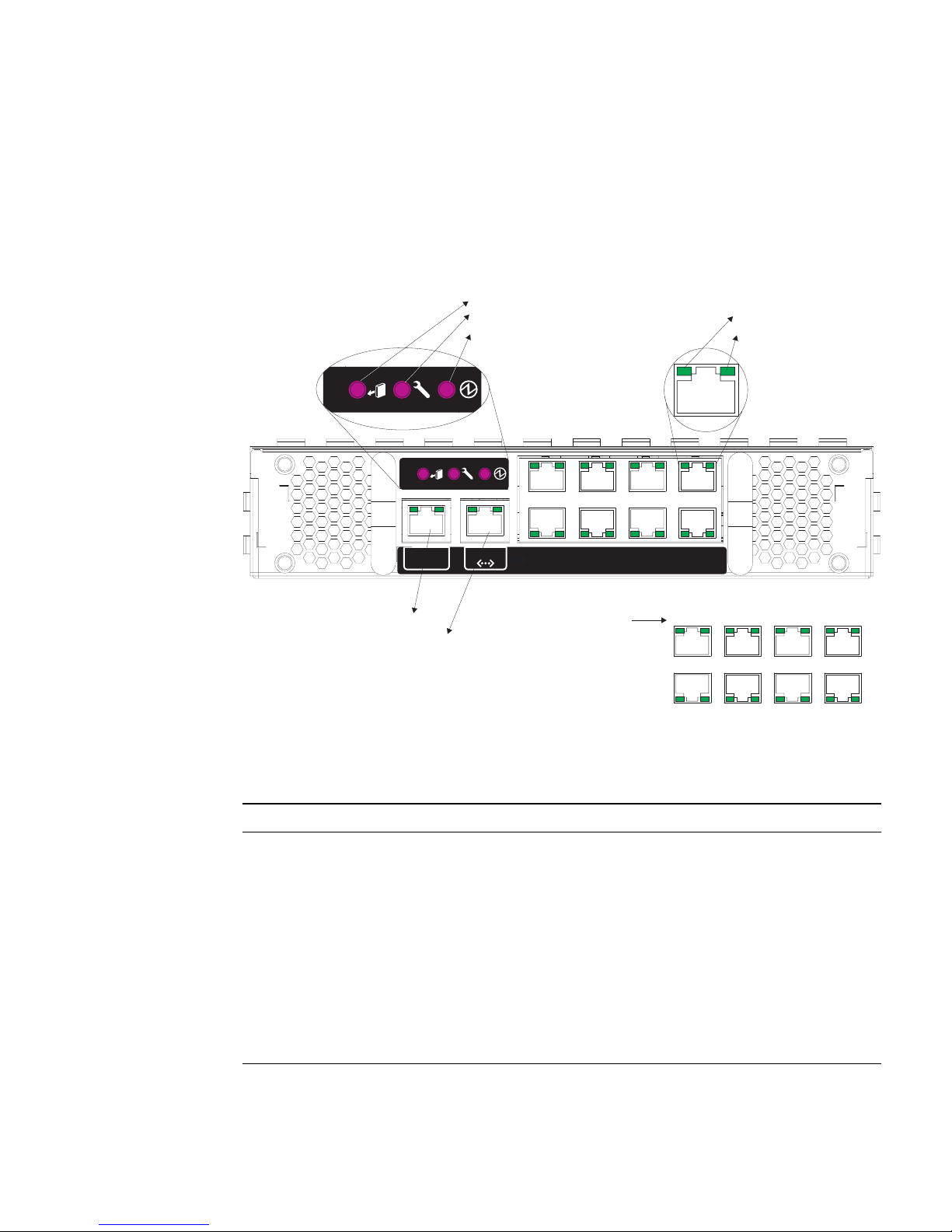
Switch level indicators are located on the SSC module. The 1000BASE-T up-link ports
and the 10/100BASE-TX management port located on the rear panel of the SSC also
include indicators for both Link and Speed.
FIGURE 1-1 SSC Exterior Panel
TABLE 1-1 Port LEDs
LED Condition Status
SSC
Active On (Green) The SSC is functioning normally.
Service Required On (Amber) The SSC requires service.
Ready to Remove On (Blue) The SSC can now be removed.
RJ-45 Ports
Link On (Green) Port has established a valid network connection.
Speed On (Amber) Link is operating at 1 Gbps.
Off Link is operating at less than 1 Gbps.
SERIAL
MGT
4
0
5
1
6
2
7
3
NET MGT
Ready to Remove
Service Required
Active
Link
Speed
Serial Mgt. Port
Network Mgt. Port
NETP4 NETP5 NETP6 NETP7
NETP0 NETP1 NETP2 NETP3
Uplink Port
Designations
Page 28

1-6 Sun Fire B1600 Blade System Chassis Switch Administration Guide • June 2003
1.3 Features of the Switch
The switch provides a wide range of advanced performance-enhancing features.
Multicast filtering provides support for real-time network applications. Port-based
and tagged virtual local area networks (VLANs), plus support for automatic GARP
VLAN Registration Protocol (GVRP) provides traffic security and efficient use of
network bandwidth. Quality of Service (QoS) priority queueing ensures the
minimum delay for moving real-time multi-media data across the network. Flow
control eliminates the loss of packets due to bottlenecks caused by port saturation.
And broadcast storm suppression prevents broadcast traffic storms from engulfing
the network. Some of the management features are briefly described in this section.
■ IEEE 802.1D Bridge – The switch supports IEEE 802.1D transparent bridging. The
address table facilitates data switching by learning addresses and then filtering or
forwarding traffic based on this information. The address table supports up to
8000 addresses.
■ Store-and-Forward Switching – The switch copies each frame into its memory
before forwarding it to another port to ensure that all frames are a standard
Ethernet size and have been verified for accuracy with the cyclic redundancy
check (CRC). This prevents bad frames from entering the network and wasting
bandwidth.
To avoid dropping frames on congested ports, the switch provides 128 Kbytes of
frame buffering per port. This buffer can queue packets awaiting transmission on
congested networks.
■ Spanning Tree Protocol – The switch supports these spanning tree protocols:
■ Spanning Tree Protocol (STP, IEEE 802.1D) – This protocol adds a level of fault
tolerance by allowing two or more redundant connections to be created
between a pair of LAN segments. When there are multiple physical paths
between segments, this protocol chooses a single path and disables all others to
ensure that only one route exists between any two stations on the network.
This prevents the creation of network loops. However, if the chosen path fails
for any reason, an alternate path will be activated to maintain the connection.
■ Rapid Spanning Tree Protocol (RSTP, IEEE 802.1w) – This protocol reduces the
convergence time for network topology changes to about 10% of that required
by the older IEEE 802.1D STP standard. It is intended as a complete
replacement for STP, but can still interoperate with switches running the older
standard by automatically reconfiguring ports to STP-compliant mode if they
detect STP protocol messages from connected devices.
■ Virtual LANs – The switch supports up to 256 VLANs. A virtual LAN is a
collection of network nodes that share the same collision domain regardless of
their physical locations or connection points in the network. The switch supports
tagged VLANs based on the IEEE 802.1Q standard. Members of VLAN groups
Page 29

Chapter 1 Introduction 1-7
can be dynamically learned through GVRP or ports can be manually assigned to a
specific set of VLANs. This allows the switch to restrict traffic to the VLAN
groups to which a user has been assigned. By segmenting your network into
VLANs, you can:
■ Eliminate broadcast storms, which severely degrade performance in a flat
network.
■ Simplify network management for node changes and moves by remotely
configuring VLAN membership for any port, rather than having to manually
change the network connection.
■ Provide data security by restricting all traffic to the originating VLAN, except
where a connection has been configured between separate VLANs using a
router or Layer 3 switch.
■ Port Mirroring – The switch can unobtrusively mirror traffic from any port to a
monitor port. You can then connect a protocol analyzer or RMON probe to this
port to perform traffic analysis and verify connection integrity.
■ Link aggregation – Ports can be combined into an aggregate link. Aggregate links
can be manually set up or dynamically configured using IEEE 802.3ad Link
Aggregation Control Protocol (LACP). The additional ports dramatically increase
the throughput across any connection, and provide redundancy by taking over
the load if a port in the trunk fails. The switch supports six aggregated links, with
up to four up-link ports per aggregated link or up to two down-link ports per
aggregated link.
■ Port Security – Port security prevents unauthorized users from accessing your
network. It enables each port to learn, or be assigned, a list of MAC addresses for
devices authorized to access the network through that port. Any packet received
on the port must have a source address that appears in the authorized list,
otherwise it will be dropped. Port security is disabled on all ports by default, but
can be enabled on a per-port basis.
■ Broadcast Suppression – Broadcast suppression prevents broadcast traffic from
overwhelming the network. When enabled on a port, the level of broadcast traffic
passing through the port is restricted. If broadcast traffic rises above a pre-defined
threshold, it is throttled until the level falls back beneath the threshold.
■ Flow Control – Flow control reduces traffic during periods of congestion and
prevent packets from being dropped when port buffers overflow. The switch
supports flow control based on the IEEE 802.3x standard. By default, flow control
is disabled on all ports.
■ Traffic Priority – This switch provides Quality of Service (QoS) by prioritizing
each packet based on the required level of service, using four priority queues with
Weighted Round Robin queuing. The switch uses IEEE 802.1p and 802.1Q tags to
prioritize incoming traffic based on input from the end-station application. These
functions can be used to provide independent priorities for delay-sensitive data
and best-effort data.
Page 30

1-8 Sun Fire B1600 Blade System Chassis Switch Administration Guide • June 2003
This switch also supports several common methods of prioritizing layer 3/4
traffic to meet application requirements. Traffic can be prioritized based on the
priority bits in the IP frame’s Type of Service (ToS) octet. When these services are
enabled, the priorities are mapped to a Class of Service value by the switch, and
the traffic is then sent to the corresponding output queue.
■ Address Filtering – This switch provides a packet filter for all traffic entering the
CPU port and potentially forwarded or routed to the management network. The
packet filter is rule/pattern-based and constitutes a set of patterns that when
matched DROPS the packet, and a further set of patterns that when matched
ACCEPTS the packet.
■ Multicast Switching – Specific multicast traffic can be assigned to its own VLAN
to ensure that it does not interfere with normal network traffic and to guarantee
real-time delivery by setting the required priority level for the designated VLAN.
The switch uses IGMP Snooping and IGMP to manage multicast group
registration.
Page 31

Chapter 1 Introduction 1-9
1.4 Switch Default Settings
TABLE 1-2 Switch Default Settings
Function Default
System Settings
• Web Mgt. Enabled
• Secure Web Mgt. Disabled
• BOOTP Enabled
• DHCP Enabled
• SNMP Communities public: Read Only
private: Read/Write
• SNMP Traps Authentication traps: enabled
Link up down events: enabled
• User Name admin (for console, Telnet, Web)
guest (for console, Telnet, Web)
• Password logon -
user admin, password admin
user guest, password guest
Change from Normal Exec to Privileged Exec: super
Serial Port Baud rate: 9600, Data bits: 8, Stop bits: 1, Parity: none
IP Settings Address: 0.0.0.0, Subnet mask: 255.0.0.0
Port Status
• Port Speed Port SNP0-15: 1000 Mbps
Port NETP0-7: 10/100/1000 Mbps, auto-negotiated
Port NETMGT: 10/100 Mbps, auto-negotiated
• Duplex Mode Port SNP0-15: full
Port NETP0-7, NETMGT: half- and full-duplex, auto-negotiated
• Flow Control Disabled
Port Priority Ingress priority: 0
Port Security Disabled
Spanning Tree Protocol Enabled, Default RSTP
(Defaults: All parameters based on IEEE 802.1w)
Page 32

1-10 Sun Fire B1600 Blade System Chassis Switch Administration Guide • June 2003
• Edge Port
(Fast Forwarding)
Enabled by default for SNP0-15, disabled for NETP0-7
Address Aging 300 seconds
Virtual LANs
• GVRP Disabled
• Default VLAN PVID 1 (for untagged frames)
• Management VLAN VLAN 2 (for the management port)
• Tagging RX: All frames, TX: Untagged frames
• Ingress Filtering Disabled
Multicast Filtering
• IGMP Snooping Enabled
ARP Enabled
• Cache Timeout 20 minutes
TABLE 1-2 Switch Default Settings (Continued)
Function Default
Page 33

2-1
CHAPTER
2
Initial Configuration
For full information about performing the initial configuration of the switch, refer to
the Sun Fire B1600 Blade System Chassis Software Setup Guide.
This chapter contains the following sections:
■ Section 2.1, “Connecting to the Switch Interface” on page 2-2
■ Section 2.2, “Enabling SNMP Management Access” on page 2-3
Page 34

2-2 Sun Fire B1600 Blade System Chassis Switch Administration Guide • June 2003
2.1 Connecting to the Switch Interface
2.1.1 Configuration Options
For management access, the switch module provides a command-line configuration
interface (CLI). This program can be accessed by first connecting to the RJ-45 serial
console port on the switch, and then logging into the switch’s CLI from the System
Controller’s (SC) command prompt as shown below, where SSCn indicates either
SSC0 or SSC1.
Note – You can use a telnet or a web connection to the switch provided that you
have set up a DHCP server on your management network. To ensure that the switch
receives the same address each time it boots (and makes a DHCP request), you need
to specify the following client identifier on your DHCP server: SUNW,SWITCH_ID=
serial number of chassis, 0 (for the switch in SSC0) or SUNW,SWITCH_ID=serial
number of chassis, 1 (for the switch in SSC1). For information about preparing the
network to receive the system chassis, and about all procedures for performing the
initial configuration of the switch, refer to the Sun Fire B1600 Blade System Chassis
Software Setup Guide.
2.1.1.1 Configuring the Switch Through the Built-in Switch Interfaces
Console Connection – You can access the switch’s CLI by typing
console sscn/swt at the System Controller command prompt, where n is either 0
or 1 depending on whether the switch whose console you want to access is in SSC0
or SSC1.
Telnet Connection – You can connect to the switch’s CLI remotely by a Telnet
connection over the management network.
sc>: console sscn/swt
Username: admin
Password:
CLI session with the Sun Fire B1600 is opened.
To end the CLI session, enter [Exit].
Console#
Page 35

Chapter 2 Initial Configuration 2-3
Web Interface – The switch also includes an embedded HTTP Web agent. This agent
can be accessed using a standard Web browser from any computer on the
management network.
SNMP Software – The switch’s management agent is based on Simple Network
Management Protocol (SNMP), supporting versions 1, 2c, and 3. This SNMP agent
enables the switch to be managed from any system in the management network
using management software, such as Solstice Domain Manager
TM
software.
The system configuration program and the SNMP agent support management
functions such as:
■ Enable/disable any port
■ Set the speed/duplex mode for any port
■ Configure SNMP parameters
■ Add ports to network VLANs
■ Display system information or statistics
■ Configure the switch to join a Spanning Tree
■ Download system firmware
2.2 Enabling SNMP Management Access
The switch can be configured to accept management commands from Simple
Network Management Protocol (SNMP v1, v2c or v3) applications such as Soltice
Domain Manager. You can configure the switch to respond to SNMP requests
and/or generate SNMP traps.
When SNMP management stations send requests to the switch (either to return
information or to set a parameter), the switch provides the requested data or sets the
specified parameter. The switch can also be configured to send information to SNMP
managers (without being requested by the managers) through trap messages, which
inform the manager that certain events have occurred.
2.2.1 Community Strings
Community strings are used to control management access to SNMP stations, as well
as to authorize SNMP stations to receive trap messages from the SSC. You therefore
need to assign community strings to specified users or user groups and set the
access levels.
Page 36

2-4 Sun Fire B1600 Blade System Chassis Switch Administration Guide • June 2003
The default strings are:
■ public – With read-only access. Authorized management stations are only able
to retrieve MIB objects.
■ private – With read/write access. Authorized management stations are able to
both retrieve and modify MIB objects.
Note – If you do not intend to utilize SNMP, delete both of the default community
strings. When there are no community strings, SNMP management access to the
switch is disabled.
To configure a community string:
1. From the Privileged Exec level global configuration mode prompt, type snmp-
server community string mode, where string is the community access string and
mode is rw (read/write) or ro (read only). Press Enter.
2. To remove an existing string, type no snmp-server community string, where
string is the community access string to remove. Press Enter.
2.2.2 Trap Receivers
You can also specify SNMP stations that are to receive traps from the SSC.
To configure a trap receiver:
1. From the Global Configuration mode prompt, type snmp-server host hostaddress community-string, where host-address is the IP address for the trap receiver
and community-string is the string associated with that host. Press Enter.
2. To configure the SSC to send SNMP notifications, you must enter at least one
snmp-server enable traps command.
Type snmp-server enable traps type, where type is either authentication or
link-up-down. Press Enter.
Console(config)#snmp-server community sun rw
Console(config)#no snmp-server community private
Console(config)#
Console(config)#snmp-server host 10.1.0.9 sun
Console(config)#snmp-server enable traps link-up-down
Console(config)#
Page 37

Chapter 2 Initial Configuration 2-5
3. Save the configuration settings by following the instructions in the Sun Fire B1600
Blade System Chassis Software Setup Guide.
Page 38

2-6 Sun Fire B1600 Blade System Chassis Switch Administration Guide • June 2003
Page 39

3-1
CHAPTER
3
General Management of the Switch
This chapter describes how to perform basic configuration tasks and includes the
following sections:
■ Section 3.1, “Using the Web Interface” on page 3-2
■ Section 3.2, “Basic Configuration” on page 3-8
■ Section 3.3, “Configuring Global Network Protocols” on page 3-39
■ Section 3.4, “Port Configuration” on page 3-96
■ Section 3.5, “Monitoring Port and Management Traffic” on page 3-139
Page 40

3-2 Sun Fire B1600 Blade System Chassis Switch Administration Guide • June 2003
3.1 Using the Web Interface
The Sun Fire B1600 blade system chassis switch provides an embedded HTTP web
agent. Using a web browser, you can configure the switch and view statistics to
monitor network activity. The web agent can be accessed by any computer on the
network using a standard web browser (Internet Explorer 5.0 or above or Netscape
Navigator 6.2 or above).
Note – You can also use the command-line interface (CLI) to manage the switch
over a serial connection to the console port or though Telnet. For more information
about using the CLI, see Chapter 4,“Command-Line Reference.”
To access the switch from a web browser, perform the following tasks:
1. Configure the switch with a valid IP address, subnet mask, and default gateway
using an out-of-band serial connection, BOOTP or DHCP protocol.
For information on how to do this, refer to the Sun Fire B1600 Blade System Chassis
Software Setup Guide.
2. Set a user name and password using an out-of-band serial connection.
Access to the web agent is controlled by the same user names and passwords as the
command-line interface. (For information on how to do this, refer to the Sun Fire
B1600 Blade System Chassis Software Setup Guide.)
Note – If the path between your management station and the switch does not pass
through any device that uses the Spanning Tree Algorithm, you can set the switch
port connected to your management station to use fast forwarding to improve the
switch’s response time to management commands issued through the web interface.
(See “Admin Edge Port” on page 3-129.)
3. Type the IP address of the switch into the address bar of your web browser.
A login dialog box opens.
4. Type a user name and password in the appropriate text fields.
5. Click OK.
If the user name and password are accepted, the System Identity page (home page)
opens and you have access to switch configuration.
Note – You are allowed three attempts to enter the correct password. After the third
failed attempt, the current connection is terminated.
Page 41
Chapter 3 General Management of the Switch 3-3
3.1.1 Navigating the Web Browser Interface
To access the web-browser interface, you must first enter a user name and password.
The administrator has read/write access to all configuration parameters and
statistics. The default administrator user name and password is admin.
3.1.1.1 Home Page
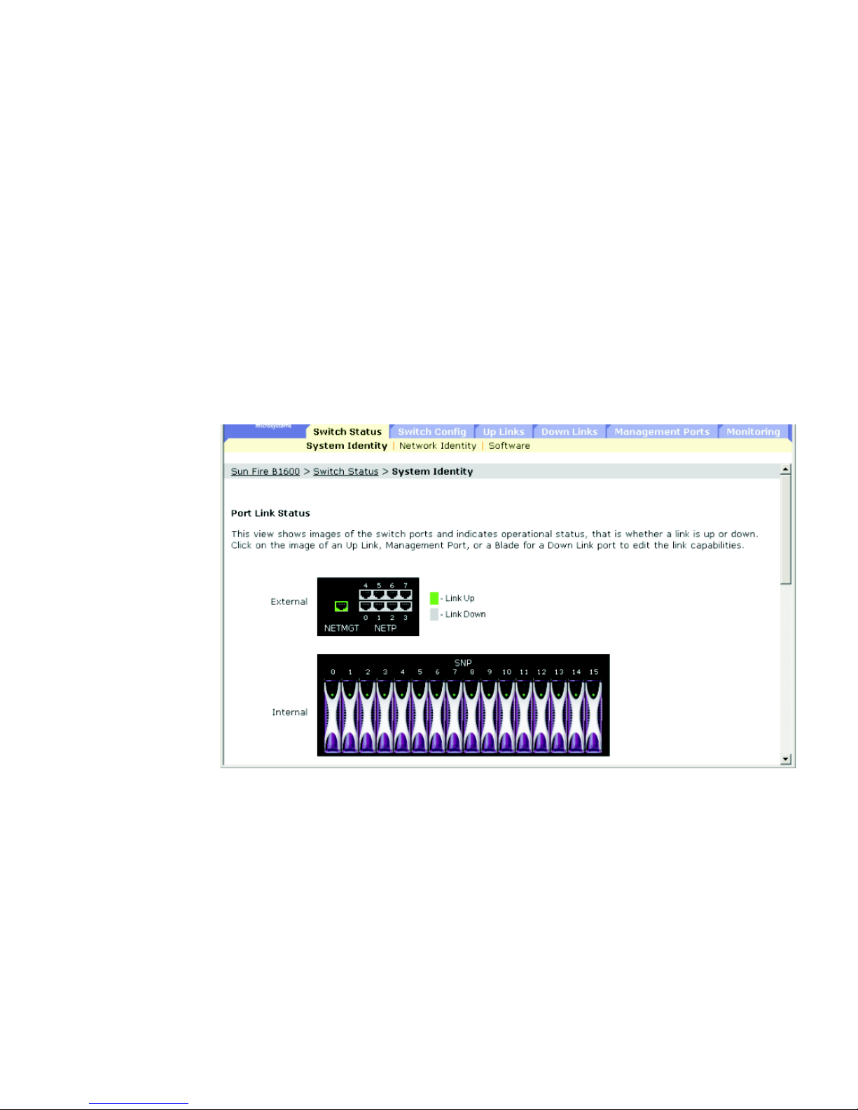
When your web browser connects with the switch’s web agent, the home page is
displayed. The configuration options are displayed in the menu tabs and
corresponding menu items (listed in the row beneath the menu tabs) at the top of the
page. The menu tabs and subordinate menu items are
used to access the
configuration menus and display configuration parameters and statistics.
FIGURE 3-1 Web GUI Home Page
Page 42
3-4 Sun Fire B1600 Blade System Chassis Switch Administration Guide • June 2003
3.1.1.2 Configuration Options
Configurable parameters have a text field or a menu. Once a configuration change
has been made on a page, click the Save button to confirm the new setting. The
following table summarizes the web page configuration buttons.
Note – To ensure proper screen refresh, confirm that Internet Explorer 5.x is
configured as follows: From the Tools menu, choose Internet Options ⇒ General ⇒
Temporary Internet Files ⇒ Settings and set “Check for newer versions of stored
pages” to “Every visit to the page.”
Note – When using Internet Explorer 5.0, you might have to click the web browser’s
refresh button to manually refresh the screen after making configuration changes.
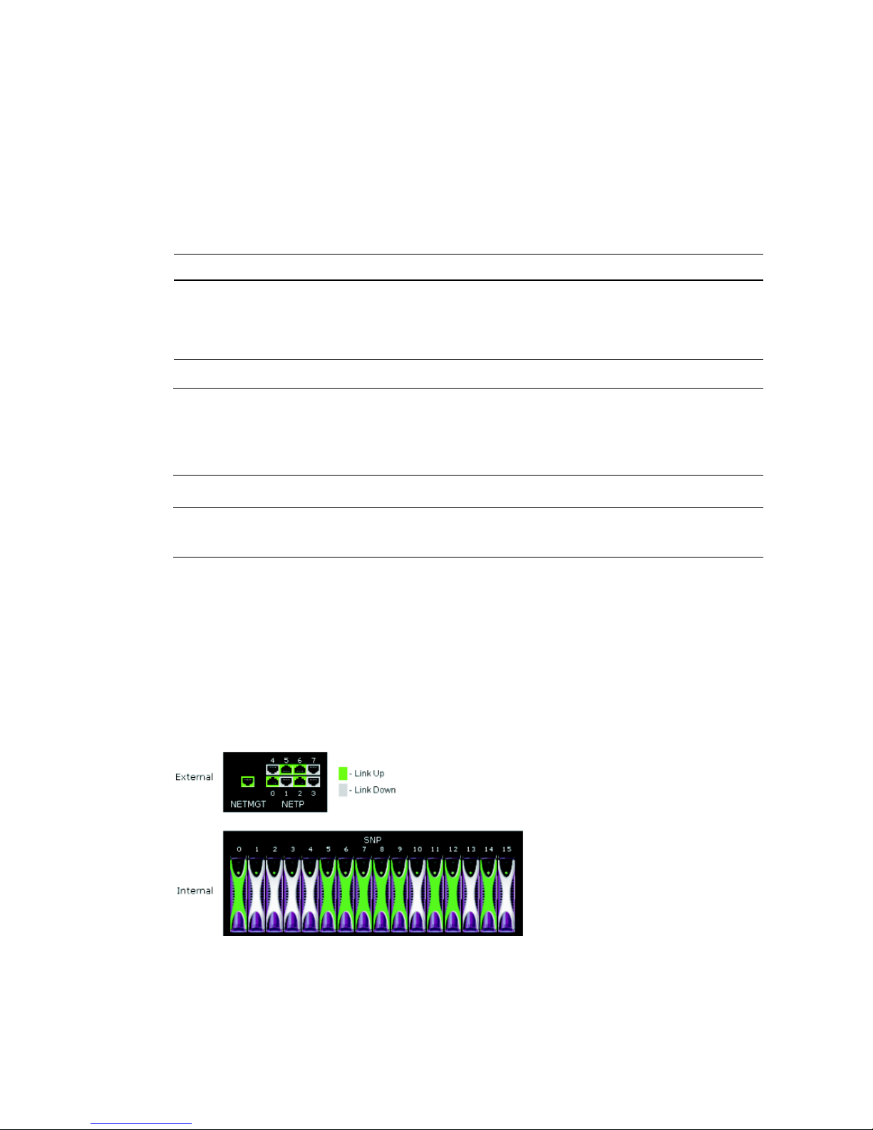
3.1.2 Panel Display
The web agent displays an image of the switch’s up-link ports, indicating whether
each link is active. Clicking on the image of a port opens the Port Configuration
page, which is described in Section 3.4, “Port Configuration” on page 3-96.
FIGURE 3-2 Image of the Switch’s Active Uplinks and Downlinks
TABLE 3-1 Web Page Configuration Buttons
Button Action
Cancel Cancels specified values and restores current values.
Reset Cancels specified values and restores current values.
Save Sets specified values to the system.
Page 43

Chapter 3 General Management of the Switch 3-5
3.1.3 Main Menu
Using the on-board web agent, you can define system parameters, manage and
control the switch and all its ports, and monitor network conditions. The following
table briefly describes the selections available from this program.
TABLE 3-2 Summary of Tasks You Can Perform Using the Web Agent
Menu Subordinate Menu Description See Page
Switch Setup Basic configuration 3-8
System Identity Provides basic system description, including
location and contact information
3-8
Network Identity Sets the IP address for management access using
DHCP, BOOTP, or manual configuration
3-12
Software Manage switch firmware code and configuration
files
3-18
Switch Config Global configuration protocols 3-39
Security Assigns user names and passwords, as well as
remote access authentication service using
RADIUS or TACACS+
3-28
Communication Sets the SNMP community access strings, trap
managers, and type of traps to issue
3-34
VLANs Displays basic VLAN information; enables GVRP
multicast protocol; configures VLANs
3-39
• Static VLAN Port
Membership
Adds static members to VLANs 3-50
Broadcast & Multicast Sets broadcast storm control; configures multicast
protocols including IGMP Snooping, static router
port information, and multicast services
3-54
• IGMP Parameters Enables multicast filtering; configures parameters
for multicast query
3-55
• Multicast Router Ports Assigns ports that are connected to a neighboring
multicast router/switch
3-59
• Multicast Services Assigns a multicast service to a specific interface 3-64
• Broadcast Parameters Sets the broadcast storm threshold 3-67
Spanning Tree Configures the Spanning Tree Protocol 3-70
• Basic Configuration Configures settings for the global spanning tree 3-70
• Advanced Configuration Configures advanced settings for RSTP 3-76
Page 44

3-6 Sun Fire B1600 Blade System Chassis Switch Administration Guide • June 2003
Class of Service Configures Class of Service 3-78
• Basic Traffic Prioritisation Configures default CoS priorities, maps CoS
priorities to output queues, and configures
Weighted Round Robin queueing
3-78
• Layer 3/4 Traffic
Prioritisation
Selects layer 3/4 priority service, maps IP
precedence tags to CoS values, and maps DSCP
tags to CoS values
3-85
Address Tables Sets address aging; displays entries for the
specified interface, VLAN or address; configures
static addresses
3-92
Up Links Port configuration 3-96
Connection Status Displays port connection status 3-96
• Connection Configuration Configures port connection settings; enables
broadcast storm control
3-102
Link Aggregation Configures ports to dynamically join aggregated
links using LACP, or specifies ports to group into
static aggregated links
3-107
VLANs Specifies port attributes (including default PVID,
switchport mode, ingress filtering, GVRP, GARP
timers; configures static VLAN members
3-114
Static Addresses Displays or edits static entries in the Address
Table; enables and disables learning of permanent
entries
3-121
Spanning Tree Configures port settings for the global spanning
tree
3-125
• Spanning Tree Protocol Configures STP port-level settings for interface(s)
on the global spanning tree
3-125
Down Links Port configuration 3-96
Connection Status Displays port connection status 3-96
• Connection Configuration Configures port connection settings; enables
broadcast storm control
3-102
Link Aggregation Configures ports to dynamically join aggregated
links using LACP, or specifies ports to group into
static aggregated links
3-107
VLANs Specifies port attributes (including default PVID,
switchport mode, ingress filtering, GVRP, GARP
timers; configures static VLAN members
3-114
TABLE 3-2 Summary of Tasks You Can Perform Using the Web Agent (Continued)
Menu Subordinate Menu Description See Page
Page 45

Chapter 3 General Management of the Switch 3-7
Static Addresses Displays or edits static entries in the Address
Table; enables and disables learning of permanent
entries
3-121
Spanning Tree Configures port settings for the global spanning
tree
3-125
• Spanning Tree Protocol Configures STP port-level settings for interface(s)
on the global spanning tree
3-125
Management
Port
Port configuration 3-96
Connection Status Displays port connection status 3-96
VLANs Specifies port attributes (including default PVID,
switchport mode, ingress filtering, GVRP, GARP
timers; configures static VLAN members
3-114
Packet Filtering Filters traffic entering the management port from
the up-link ports
3-134
Monitoring Switch monitoring functions 3-139
Port Mirroring Sets the source and target ports for mirroring 3-139
Port Statistics Displays statistics on port traffic, including
information from the Interfaces Group, Ethernetlike MIB, and RMON MIB
3-141
SNMP Statistics Displays statistics on SNMP messages 3-152
Logs Configures logging message parameters; displays
messages stored in switch memory
3-152
TABLE 3-2 Summary of Tasks You Can Perform Using the Web Agent (Continued)
Menu Subordinate Menu Description See Page
Page 46

3-8 Sun Fire B1600 Blade System Chassis Switch Administration Guide • June 2003
3.2 Basic Configuration
3.2.1 Displaying System Information
You can identify the system by providing a descriptive name, location, and contact
information.
When displaying system information using the web interface or CLI, the following
parameters are displayed or can be configured:
■ Host Name – The name assigned to the switch.
■ Location – The system chassis location.
■ Contact – The administrator responsible for the system.
■ System Up Time – The length of time the management agent has been up.
■ System Description – The system hardware description assigned by the
manufacturer.
■ Serial Number
1
– The serial number of the main board.
■ System OID string
2
– The MIB II object ID for switch’s network management
subsystem.
■ MAC Address
3
– The physical layer address for the switch.
■ Web server
2
– The operational status of web (HTTP) management access on the
switch.
■ Web server port
2
– The TCP port number used by the web interface.
■ POST result
2
– The results of the switch power-on self-test.
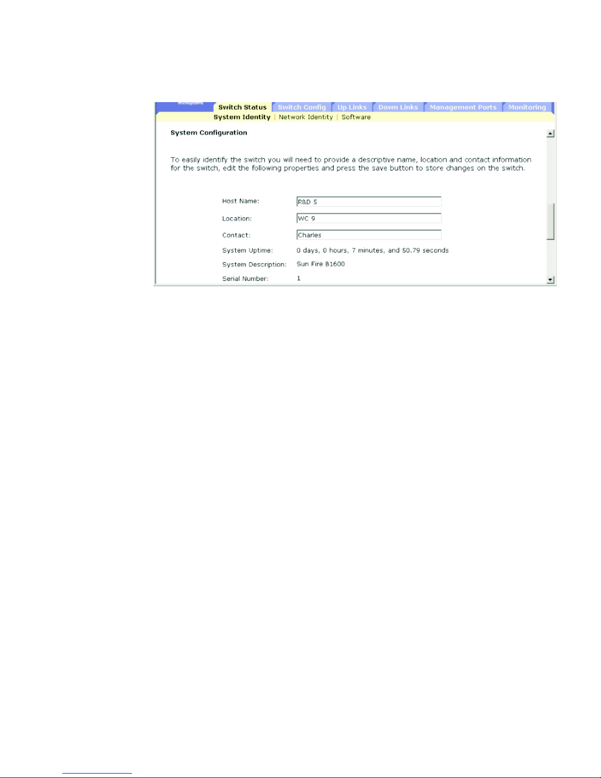
3.2.1.1 Web Interface: Displaying and Specifying Identification
Details
1. Open the Switch Setup ⇒ System Identity window.
2. Specify the host name, location, and contact information for the system
administrator.
3. Click Save.
1. CLI: See“show version”on page 4-44
2. CLI only
3. Web: See“Setting theIP Address” onpage 3-12
Page 47
Chapter 3 General Management of the Switch 3-9
FIGURE 3-3 Switch Setup ⇒ System Identity Window
Page 48

3-10 Sun Fire B1600 Blade System Chassis Switch Administration Guide • June 2003
3.2.1.2 Command-line Interface: Displaying and Specifying
Identification Details
FIGURE 3-4 CLI Commands for Specifying Host Name, Location, and Contact
Information.
Console(config)#hostname R&D 5
Console(config)#snmp-server location WC 9
Console(config)#snmp-server contact Charles
Console#show system
System description: Sun Fire B1600
System OID string: 1.3.6.1.4.1.674.10895.4
System information
System Up time: 0 days, 0 hours, 55 minutes, and 54.91 seconds
System Name : [NONE]
System Location : [NONE]
System Contact : [NONE]
MAC address : 00-00-e8-00-00-01
Web server : enable
Web server port : 80
Web secure server : enable
Web secure server port : 443
POST result
--- Performing Power-On Self Tests (POST) ---
UART Loopback Test ..................... PASS
Timer Test ............................. PASS
DRAM Test .............................. PASS
I2C Initialization ..................... PASS
Runtime Image Check .................... PASS
PCI Device Check ....................... PASS
Switch Driver Initialization ........... PASS
------------------- DONE -------------------Console#
Page 49

Chapter 3 General Management of the Switch 3-11
3.2.1.3 MIB Variables: Identification Details
TABLE 3-3 SNMP MIB variables Corresponding to the Switch Setup ⇒ System Identity
Window
Field Name MIB Variable Access Value Range Default Value
System Name
(Host Name)
MIB-II.
system.
sysName
Read/write String (size(0-255))
System Location MIB-II.
system.
sysLocation
Read/write String (size(0-255))
System Contact MIB-II.
system.
sysContact
Read/write String (size(0-255))
System Up Time MIB-II.
system.
sysUpTime
Read only Timeticks
(in centiseconds)
System
Description
MIB-II.
system.
sysDescr
Read only String (size(0-255))
System Object
Identification
MIB-II.
system.
sysObjectID
Read only Object identifier
MAC Address MIB-II.
interfaces.
ifTable.ifEntry.
ifPhysAddress
Read only Physical address
HTTP State
(Web Server)
sun...
ipMgt.
ipHttpState
Read/write enabled (1),
disabled (2)
enabled
HTTP Port
(Web Server
Port)
sun...
ipMgt.
ipHttpPort
Read/write Integer (1-65535) 80
HTTPS State
(Secure Server)
sun...
ipMgt.
ipHttpsState
Read/write enabled (1),
disabled (2)
enabled
HTTPS Port
(Secure Server
Port)
sun...
ipMgt.
ipHttpsPort
Read/write Integer (1-65535) 443
Page 50

3-12 Sun Fire B1600 Blade System Chassis Switch Administration Guide • June 2003
3.2.2 Setting the IP Address
By default, the switch searches for its IP address, default gateway, and netmask
using DHCP.
You can manually configure a specific IP address or direct the device to obtain an
address from a BOOTP or DHCP server. Valid IP addresses consist of four decimal
numbers, 0 to 255, separated by periods. Any other format will not be accepted by
the software.
Note – The IP address of the switch is in fact the IP address of the VLAN containing
the management port (NETMGT). By default, the management port is on VLAN 2.
Therefore, by assigning an IP address to VLAN 2 you set up network access to the
switch. Only the VLAN containing the management port should be assigned an IP
address. If you assign an IP address to any other VLAN, the original IP address is
immediately disabled and the new address takes immediate effect.
When setting the switch IP configuration using the web interface or CLI, the
following parameters are displayed or can be configured:
■ Current IP Address – The current address of the VLAN interface that is allowed
management access.
■ MAC Address
4
– The physical layer address for this switch.
■ Management VLAN – The VLAN through which you can manage the switch. By
default, the management port (NETMGT) is configured as a member of this
VLAN (that is, VLAN 2). However, if you change the Management VLAN, you
will lose management access to the switch unless the NETMGT port has already
been configured as a member of the new VLAN. If this occurs, you will have to
use the console interface to add the NETMGT port to the newly configured
Management VLAN. (See Section 4.3.12.8, “switchport allowed vlan” on
page -127.)
■ IP Address Mode – The method through which IP functionality is enabled. The
options are manual configuration (Static), Dynamic Host Configuration Protocol
(DHCP), or Boot Protocol (BOOTP). If DHCP/BOOTP is enabled, IP will not
function until a reply has been received from the server. Requests are broadcast
periodically by the switch for IP configuration settings. (DHCP/BOOTP values
can include the IP address, subnet mask, and default gateway.)
■ DHCP – Dynamic Host Configuration Protocol
Enable Client ID – Includes a client identifier in all communications with the
DHCP server.
4. CLI: See“Displaying SystemInformation” onpage 3-8.
Page 51

Chapter 3 General Management of the Switch 3-13
Text / Hex – Indicates whether the client ID has been entered as a text string
(1-15 characters) or as a hexidecimal value. The data type used will depend
on the requirements of your DHCP server.
Note – The Client ID specified in this menu will be overwritten by the SC the next
time the system, or the switch itself, is rebooted. The Client ID field will be removed
from the next firmware release.
■ BOOTP – Boot Protocol
■ Manual – The IP parameters are set to specified values.
■ IP Address – The address of the VLAN interface that is allowed management
access. Valid IP addresses consist of four numbers, 0 to 255, and separated by
periods. The default is 0.0.0.0.
■ Subnet Mask – The mask that identifies the host address bits used for routing
to specific subnets. The default is 255.0.0.0.
■ Broadcast Address
5
– The IP broadcast address used for sending datagrams on
the interface associated with the IP address. This value applies to both the
subnet and network broadcast addresses used by the switch. The default is
0.0.0.1.
■ Gateway IP Address – The IP address of the gateway router between this
device and management stations that exist on other network segments. The
default is 0.0.0.0.
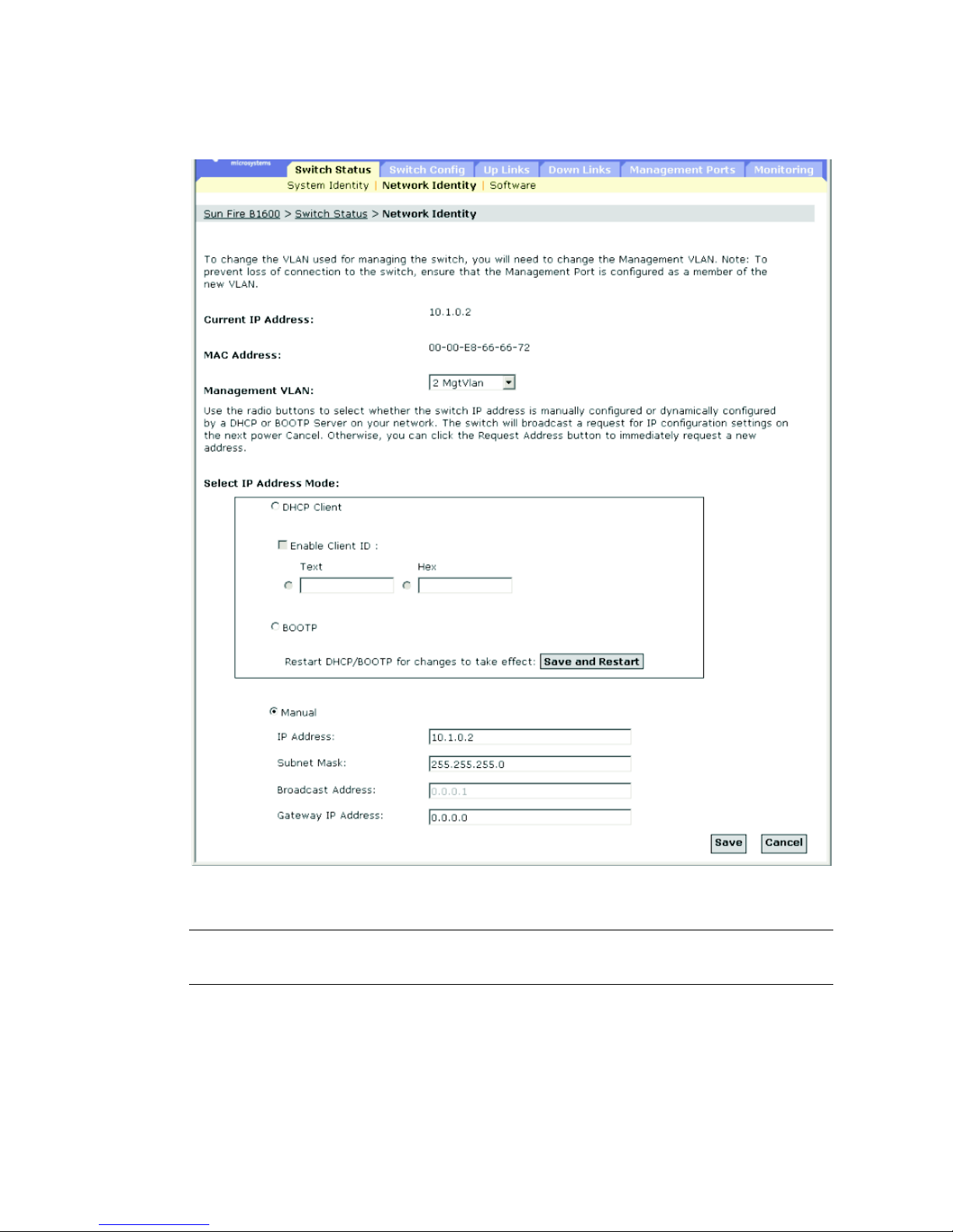
3.2.2.1 Manual Configuration
Web Interface: Specifying the Management VLAN and IP Details
1. Open Switch Setup ⇒ Network Identity.
2. Select the management VLAN interface.
3. Select the Manual IP Address Mode.
4. Specify the IP address, subnet mask, and default gateway.
5. Click Save.
5. Web only
Page 52
3-14 Sun Fire B1600 Blade System Chassis Switch Administration Guide • June 2003
FIGURE 3-5 Open Switch Setup ⇒ Network Identity Window
Note – If you receive an error message saying that the data you have entered is
invalid, confirm that you have specified each of the IP addresses correctly.
Page 53

Chapter 3 General Management of the Switch 3-15
Command-line Interface: Specifying the Management VLAN and IP
Details
● Specify the management interface, IP address, and default gateway:
MIB Variables: Specifying the Management VLAN and IP Details
Console#config
Console(config)#interface vlan 2
Console(config-if)#ip address 10.1.0.2 255.255.255.0
Console(config-if)#exit
Console(config)#ip default-gateway 10.1.0.254
Console(config)#
TABLE 3-4 MIB Variables for Specifying the Management VLAND and IP Details
Field Name MIB Variable Access Value Range Default Value
Management
VLAN
sun...
switchMgt.
switchManagementVla
n
Read/write Integer (1-4094) 1
IP Address Mode sun...
vlanMgt.
vlanTable.vlanEntry
.
vlanAddressMethod
Read/write user (1),
bootp (2),
dhcp (3)
user
IP Address
Configuration
MIB-II.
ip.ipAddrTable.
ipAddrEntry.
ipAdEntAddr
Read/write IP address
Subnet Mask
Configuration
MIB-II.
ip.ipAddrTable.
ipAddrEntry.
ipAdEntNetMask
Read/write IP address
Broadcast
Address
MIB-II.
ip.ipAddrTable.
ipAddrEntry.
ipAdEntBcastAddr
Read only Integer (0-1) 1
Default Gateway
Configuration
sun...
ipMgt.
netDefaultGateway
Read/write IP address
Page 54
3-16 Sun Fire B1600 Blade System Chassis Switch Administration Guide • June 2003
3.2.2.2 Using DHCP/BOOTP
By default, the switch uses DHCP/BOOTP services to find its IP configuration
information.
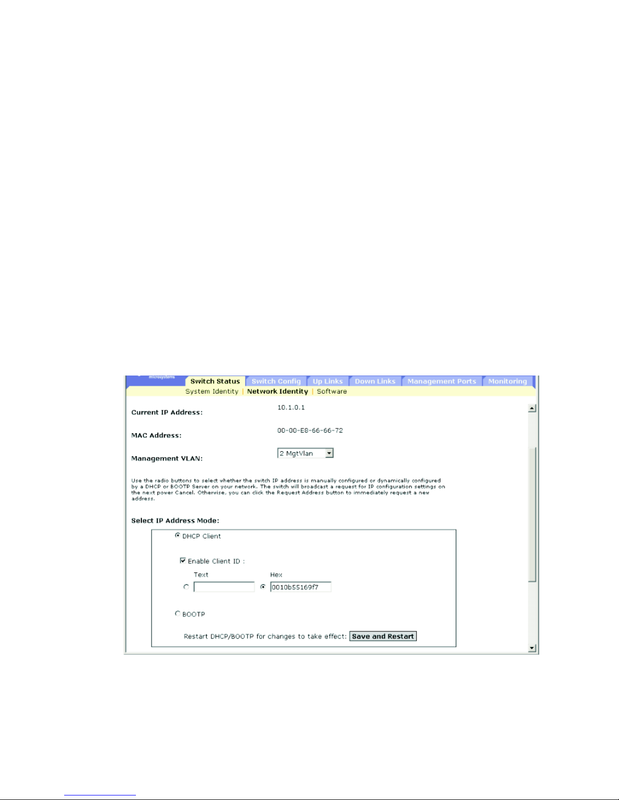
Web Interface: Using Dynamic IP Configuration Services
1. Open Switch Setup ⇒ Network Identity.
2. Specify the management VLAN interface.
3. Specify the IP Address Mode by selecting DHCP or BOOTP.
By default, the System Controller in the chassis provides a client identifier to the
switch. The client identifier is SUNW,SWITCH_ID=serial number of chassis,0 or
SUNW,SWITCH_ID=serial number of chassis,1 (depending on whether the switch is in
SSC0 or SSC1). You can specify a client identifier in the Enable Client ID checkbox,
but it will be overwritten the next time the System Controller resets or boots. Do not
do this. The Enable Client ID field will be removed from future versions of the
firmware.
FIGURE 3-6 Open Switch Setup ⇒ Network Identity Window (Showing
DHCP/BOOTP Radio Buttons)
Page 55

Chapter 3 General Management of the Switch 3-17
If the address assigned by DHCP is no longer functioning, you will not be able to
renew the IP settings through the web interface. You can only restart the DHCP
service through the web interface if the current address is still valid.
Note – If you lose your management connection, use a console connection and the
show ip interface command to determine the new switch address.
Note – The Client ID specified in this menu will be overwritten by the SC the next
time the System Controller, or the switch itself, is rebooted. The Client ID field will
be removed from the next firmware release.
Command-line Interface: Using Dynamic IP Configuration Services
1. Specify the management interface.
2. Set the IP address mode to DHCP or BOOTP.
3. Issue the ip dhcp restart command.
DHCP may lease addresses to clients indefinitely or for a specific period of time. If
the address expires or the switch is moved to another network segment, you will
lose management access to the switch. In this case, you can reboot the switch or
submit a client request to restart DHCP service.
Type the following command to restart DHCP service:
Console#config
Console(config)#interface vlan 2
Console(config-if)#ip address dhcp
Console(config-if)#ip dhcp client-id hex 00-00-e8-66-65-72
Console(config-if)#end
Console#ip dhcp restart
Console#show ip interface
IP address and netmask: 10.1.0.54 255.255.255.0 on VLAN 2,
and address mode: DHCP.
Console#
Console#ip dhcp restart
Page 56

3-18 Sun Fire B1600 Blade System Chassis Switch Administration Guide • June 2003
MIB variables: Using Dynamic IP Configuration Services
3.2.3 Displaying Switch Software Versions
When displaying switch software versions using the web interface or CLI, the
following parameters are displayed:
■ Loader Version – The version number of the loader code.
■ Boot-ROM Version – The version number of the boot code.
■ Operation Code Version – The version number of the runtime code.
■ Unit ID
6
– The ID of the active switch. (This value will always be 1.)
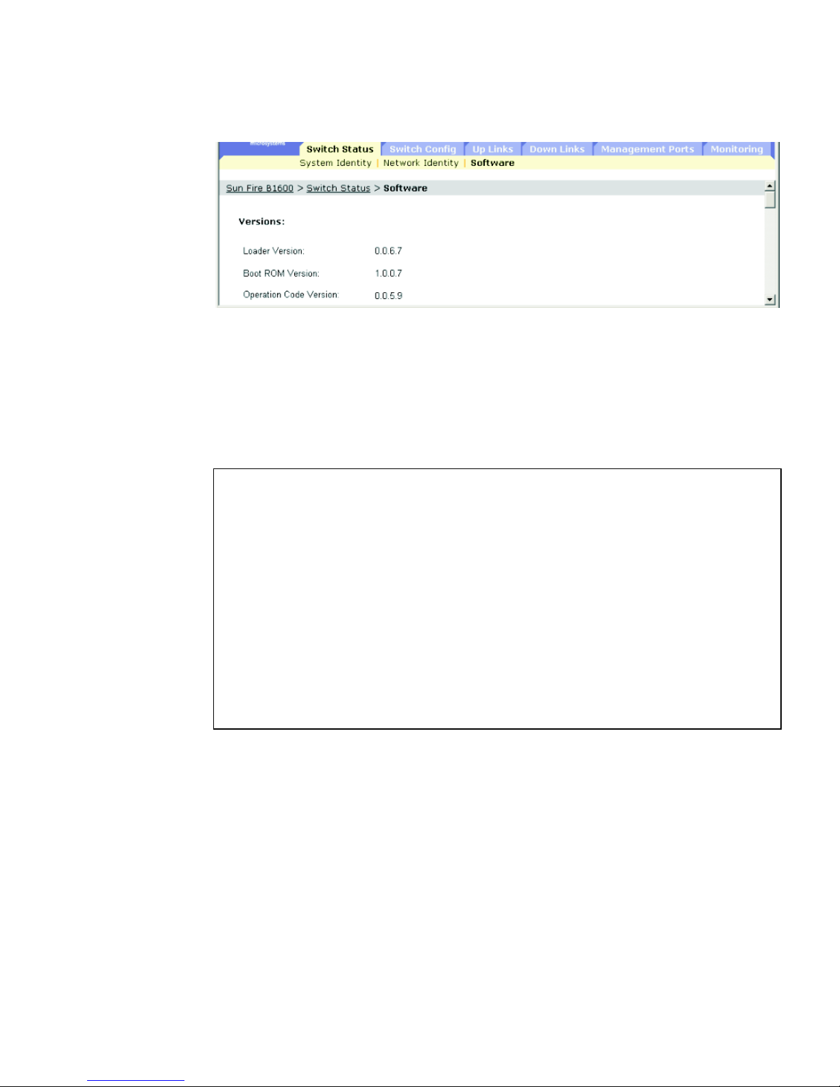
3.2.3.1 Web Interface: Displaying Switch Software Version
Information
● Open Switch Status ⇒ Software.
TABLE 3-5 MIB Variables Associated With Dynamic IP Configuration Services
Field Name MIB Variable Access Value Range Default Value
Management
VLAN
sun...
switchMgt.
switchManagementVlan
Read/write Integer (1-4094) 1
IP Address Mode sun...
vlanMgt.
vlanTable.vlanEntry.
vlanAddressMethod
Read/write user (1),
bootp (2),
dhcp (3)
dchp
DHCP Client ID sun...
ipMgt.
dhcpClientIfClientId
Read/write Octet string
(MAC address)
DHCP Restart sun...
ipMgt.
ipDhcpRestart
Read/write restart (1),
noRestart (2)
noRestart
6. CLI only. Thevalue ofUnit IDhas nosignificance in the current versionof theswitch inthe SunFire B1600
blade systemchassis.
Page 57
Chapter 3 General Management of the Switch 3-19
FIGURE 3-7 Open Switch Setup ⇒ Software Window (showing version information)
3.2.3.2 Comand-line Interface: Displaying Switch Software Version
Information
Use the following command to display version information:
Console#show version
Unit1
Serial number :1
Service tag :
Hardware version :R0B
Number of ports :25
Main power status :up
Redundant power status :not present
Agent(master)
Unit id :1
Loader version :0.0.6.5
Boot rom version :0.0.7.3
Operation code version :1.0.0.1
Console#
Page 58

3-20 Sun Fire B1600 Blade System Chassis Switch Administration Guide • June 2003
3.2.3.3 MIB Variables Associated With Software Version Information
TABLE 3-6 MIB Versions Associated With Software Version Information
Field Name MIB Variable Access Value Range Default Value
Switch Serial
Number
SUN.
switchMgt.
switchInfoTable.
switchInfoEntry.
swSerialNumber
Read only Display string
(size (0..80))
Switch
Hardware
Version
SUN.
switchMgt.
switchInfoTable.
switchInfoEntry.
swHardwareVer
Read only Display string
(size (0..20))
Switch Port
Number
SUN.
switchMgt.
switchInfoTable.
switchInfoEntry.
swPortNumber
Read only Integer 25
Switch Unit
Index
SUN.
switchMgt.
switchInfoTable.
switchInfoEntry.
swUnitIndex
Notaccessible
Integer 1
Switch Loader
Version
sun...
switchMgt.
switchInfoTable.
switchInfoEntry.
swLoaderVer
Read only String (size (0-20))
Switch Boot
Rom Version
sun...
switchMgt.
switchInfoTable.
switchInfoEntry.
swBootRomVer
Read only String (size (0-20))
Switch
Operation
Code Version
sun...
switchMgt.
switchInfoTable.
switchInfoEntry.
swOpCodeVer
Read only String (size (0-20))
Page 59

Chapter 3 General Management of the Switch 3-21
3.2.4 Managing Firmware
You can upload and download firmware to and from a TFTP server. By saving
runtime code to a file on a TFTP server, that file can later be downloaded to the
switch to restore operation. You can also set the switch to use new firmware without
overwriting the previous version.
When downloading software files, note the following points:
■ The destination file name should not contain slashes (\ or /).
■ The leading character of the file name should not be a period (.).
■ The maximum length for file names on the TFTP server is 127 characters.
■ The maximum length for file names on the switch is 32 characters.
■ Valid characters are A-Z, a-z, 0-9, “.”, “-”, and “_”.
■ Only two copies of the System Software file (containing the runtime firmware)
can be stored in the file directory on the switch. The currently designated startup
version of this file cannot be deleted. If there are two copies of the System
Software file present, you can delete the one that is not currently designated as
the startup version and replace it with a new file, or you can copy a new one into
the directory using one of the existing file names. Alternatively you can remove
the startup designation from the current startup file, delete that file, copy a new
version of the System Software file into the directory, and finally make the new
file the designated startup file.
3.2.4.1 Downloading Switch Firmware From a Server
When downloading runtime code, you can specify the destination file name to
overwrite the current image, or first download the file to a different file name and
then set the new file as the startup file.
Web Interface: Downloading Switch Firmware
1. Open the Switch Status ⇒ Software window.
2. Type the IP address of the TFTP server.
3. Type the file name of the software to download, select a file on the switch to
overwrite, or specify a new file name.
4. Click Download.
Page 60
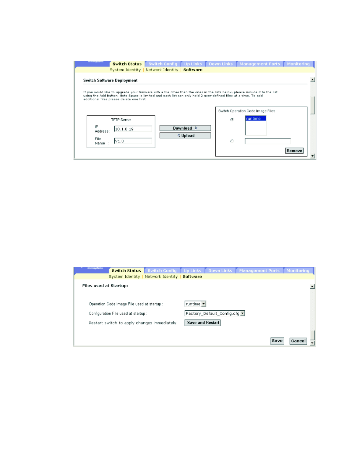
3-22 Sun Fire B1600 Blade System Chassis Switch Administration Guide • June 2003
FIGURE 3-8 The Switch Status ⇒ Software Window (for downloading firmware)
Note – If you receive an error message saying that the data you have entered is
invalid, you might have typed an incorrect IP address or an incorrect file name, or
you not might have the correct access permissions for TFTP transfer. Alternatively, it
is possible that there is not enough memory available on the switch.
If you download to a new destination file, select the new file from the pull-down
menu for the operation code used at startup and click Save. To start the new
firmware, reboot the system by clicking Save and Restart.
FIGURE 3-9 The Switch Status ⇒ Software Window (at the End of the Download Process)
Command-line Interface: Dowloading Switch Firmware
1. Type the IP address of the TFTP server.
2. Select config or opcode file type.
Page 61

Chapter 3 General Management of the Switch 3-23
3. Type the source and destination file names.
4. Set the new file to start up the system.
5. Restart the switch.
To start new firmware, use the reload command to reboot the system.
MIB Variables Associated With Downloading Firmware
Console#copy tftp file
TFTP server ip address: 10.1.0.99
Choose file type:
1. config: 2. opcode: <1-2>: 2
Source file name: v10.bix
Destination file name: V10000
\Write to FLASH Programming.
-Write to FLASH finish.
Success.
Console#config
Console(config)#boot system opcode: V10000
Console(config)#exit
Console#reload
TABLE 3-7 MIB Variables Associated With Downloading Firmware
Field Name MIB Variable Access Value Range
Switch
Operation
Code Image
Files
Not defined
TFTP Server IP
Address
sun...
tftpMgt.
tftpServer
Read/write IP address
TFTP File Type sun...
tftpMgt.
tftpFileType
Read/write opcode (1),
config (2)
TFTP Source
File Name
sun...
tftpMgt.
tftpSrcFile
Read/write String (size (0-127))
Page 62

3-24 Sun Fire B1600 Blade System Chassis Switch Administration Guide • June 2003
TFTP
Destination
File Name
sun...
tftpMgt.
tftpDestFile
Read/write String (size (0-127))
TFTP Action sun...
tftpMgt.
tftpAction
Read/write notDownloading (1),
downloadToPROM (2),
downloadToRAM (3) (not
supported)
upload (4)
TFTP Status sun...
tftpMgt.
tftpStatus
Read/write tftpSuccess (1),
tftpStatusUnknown (2),
tftpGeneralError (3),
tftpNoResponseFromServer (4),
tftpDownloadChecksumError (5),
tftpDownloadIncompatible
Image(6),
tftpTftpFileNotFound(7),
tftpTftpAccessViolation(8)
Restart
Operation
Code File
sun...
restartMgt.
restartOpCodeFile
Read/write Display String (Size (0-127))
Restart Action sun...
restartMgt.
restartControl
Read/write running (1),
warmBoot (2),
coldBoot (3)
TABLE 3-7 MIB Variables Associated With Downloading Firmware (Continued)
Field Name MIB Variable Access Value Range
Page 63

Chapter 3 General Management of the Switch 3-25
3.2.5 Saving or Restoring Configuration Settings
You can upload and download configuration settings to and from a TFTP server. The
configuration file can later be downloaded to restore the switch’s settings.
When downloading configuration files, note the following points:
■ The destination file name should not contain slashes (\ or /).
■ The leading character of the file name should not be a period (.).
■ The maximum length for file names on the TFTP server is 127 characters.
■ The maximum length for file names on the switch is 32 characters.
■ Valid characters are A-Z, a-z, 0-9, “.”, “-”, and “_”.
■ The maximum number of user-defined configuration files is limited by available
memory.
3.2.5.1 Downloading Configuration Settings From a Server
You can download the configuration file under a new file name and then set it as the
startup file, or you can specify the current startup configuration file as the
destination file to overwrite it. Note that Factory_Default_Config.cfg can be
copied to the TFTP server but cannot be used as the destination on the switch (it
cannot be overwritten).
Web Interface: Downloading a File of Configuration Settings
1. Open the Switch Setup ⇒ Software window.
2. Type the IP address of the TFTP server.
3. Type the name of the file to download, select a file on the switch to overwrite, or
specify a new file name.
4. Click Download.
Page 64
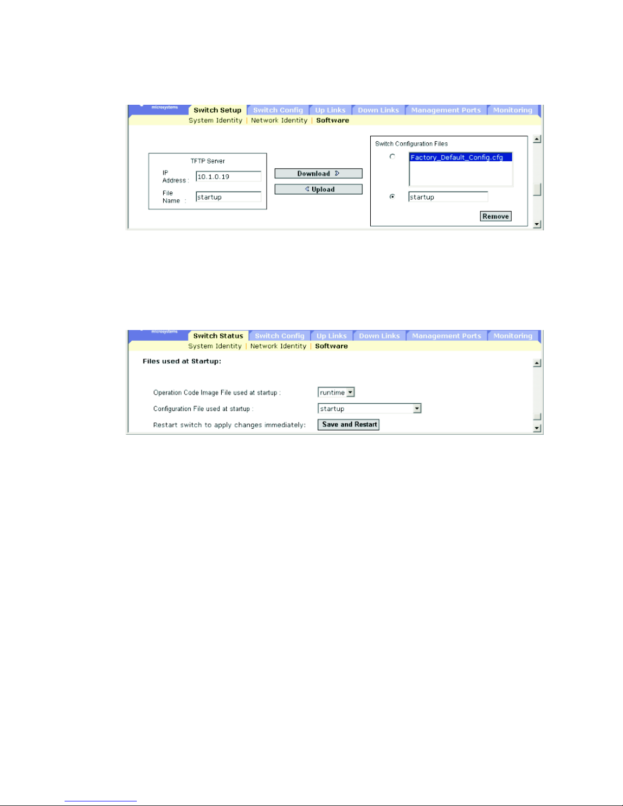
3-26 Sun Fire B1600 Blade System Chassis Switch Administration Guide • June 2003
FIGURE 3-10 The Switch Setup ⇒ Software Window (for downloading a configuration file)
If you download to a new file name, select the new file from the pull-down menu
and click Save. To use the new settings, reboot the system by clicking Save and
Restart.
FIGURE 3-11 The Switch Setup ⇒ Software Window (enabling you to specify the operation
code and configuration file to use at startup)
Command-line Interface: Downloading a File of Configuration Settings
1. Type the IP address of the TFTP server.
2. Specify the source file on the server.
3. Set the startup file on the switch.
Page 65

Chapter 3 General Management of the Switch 3-27
4. Restart the switch.
If you download the startup configuration file under a new file name, you can set
this file as the startup file at a later time, and then restart the switch.
MIB Variables Associated With Downloading Configuration Settings
Console#copy tftp startup-config
TFTP server ip address: 192.168.1.19
Source configuration file name: startup2.0
Startup configuration file name [startup] : startup2.0
\Write to FLASH Programming.
-Write to FLASH finish.
Success.
Console#reload
System will be restarted, continue <y/n>?y
Console#config
Console(config)#boot system config: startup-new
Console(config)#exit
Console#reload
System will be restarted, continue <y/n>?y
TABLE 3-8 MIB Variables Associated With Downloading Configuration Settings
Field Name MIB Variable Access Value Range
TFTP Server
IP Address
sun...
tftpMgt.
tftpServer
Read/write IP address
TFTP File
Type
sun...
tftpMgt.
tftpFileType
Read/write opcode (1),
config (2)
TFTP Source
File Name
sun...
tftpMgt.
tftpSrcFile
Read/write Display string (size (0-127))
TFTP Action sun...
tftpMgt.
tftpAction
Read/write notDownloading (1),
downloadToPROM (2),
downloadToRAM (3),
upload (4)
Page 66

3-28 Sun Fire B1600 Blade System Chassis Switch Administration Guide • June 2003
3.2.6 Configuring User Authentication
Use the Security menu to restrict management access based on specified user names
and passwords. You can manually configure access rights on the switch, or you can
use a remote access authentication server based on RADIUS or TACACS+ protocols.
There are two access types: Normal and Privileged. Normal level only provides
access to a limited number of commands, while Privileged level provides access to
all commands. The default administrator account has write access for all of the
parameters governing the switch. You should therefore assign a password as soon as
possible and store it in a safe place.
Note – The default administrator user name is admin with the password admin.
Note the following points about configuring user authentication:
■ By default, management access is always checked against the authentication
database stored on the local switch. If a remote authentication server is used, you
must specify the authentication sequence and the corresponding parameters for
each remote authentication protocol specified.
■ Remote Authentication Dial-in User Service (RADIUS) and Terminal Access
Controller Access Control System Plus (TACACS+) are logon authentication
protocols that use software running on a central server to control access to
TFTP Status sun...
tftpMgt.
tftpStatus
Read/write tftpSuccess (1),
tftpStatusUnknown (2),
tfttpGeneralError (3),
tftpNoResponseFromServer (4),
tftpDownloadChecksumError
(5),
tftpDownloadIncompatibleImage
(6),
tftpTftpFileNotFound(7),
tftpTftpAccessViolation(8)
Restart
Configuration
File
sun...
restartMgt.
restartConfigFile
Read/write Display string (size (0-127))
Restart Action sun...
restart.Mgt.
restartControl
Read/write running (1),
warmBoot (2),
coldBoot (3)
TABLE 3-8 MIB Variables Associated With Downloading Configuration Settings
Field Name MIB Variable Access Value Range
Page 67

Chapter 3 General Management of the Switch 3-29
RADIUS-aware or TACACS+-aware devices on the network. An authentication
server contains a database of multiple user name/password pairs with associated
privilege levels for each user that requires management access to a switch.
Note – When setting up privilege levels on a RADIUS or TACACS+ server,
remember that level 0 allows guest (Normal Exec) access to the switch. Only level 15
allows administrator (Privileged Exec) access.
■ RADIUS uses UDP while TACACS+ uses TCP. UDP only offers best effort
delivery, while TCP offers a connection-oriented transport. Also, note that
RADIUS encrypts only the password in the access-request packet from the client
to the server, while TACACS+ encrypts the entire body of the packet.
■ RADIUS and TACACS+ logon authentication controls management access
through the console port, Web browser, or Telnet. These access options must be
configured on the authentication server.
■ RADIUS and TACACS+ logon authentication assigns a specific privilege level for
each user name/password pair. The user name, password, and privilege level
must be configured on the authentication server.
■ You can specify one to three authentication methods for any user to indicate the
authentication sequence. For example, if you select (1) RADIUS and (2) Local, the
user name and password on the RADIUS server are verified first. If the RADIUS
server is not available, then the local user name and password are checked.
When configuring user authentication using the web interface or CLI, the following
parameters are displayed or can be configured:
■ Authentication Mechanisms
■ Require User Authentication – The operating status of user authentication.
■ Preference – The switch attempts to authenticate the user based on the
specified sequence.
■ Authentication Server Settings
■ Server IP Address – The address of the authentication server. The default
is: 10.1.0.1.
■ Server Port Number – The UDP or TCP network port (between 1 and 65,535) of
the authentication server used for authentication messages. The default is 1812.
■ Encryption Key – The password (between 1 and 20 characters) used to
authenticate logon access for the client. Do not use blank spaces in the string.
■ No. of Retries
7
– The number of times (between 1 and 30) the switch tries to
authenticate logon access through the authentication server. The default is 2.
7. Applies onlyto RADIUSserver authentication.
Page 68

3-30 Sun Fire B1600 Blade System Chassis Switch Administration Guide • June 2003
■ Timeout for reply
8
– Number of seconds (between 1 and 65,535) the switch
waits for a reply before resending a request. The default is 5.
■ Local Access Authentication
■ User Account – The name (between 1 and 8 characters) of the user.
The maximum number of users is 5.
■ Access Level – The user level. Specify Normal or Privileged.
■ Password – The user password. A plain text string of between 1 and 8
characters that is case sensitive.
3.2.6.1 Web Interface: Configuring User Authentication
1. Open the Switch Config ⇒ Security window.
2. Specify the authentication sequence by selecting local or remote methods for each
of the three preferences.
3. Type parameter values for the specified authentication methods.
4. Click Save.
8. Applies onlyto RADIUSserver authentication.
Page 69
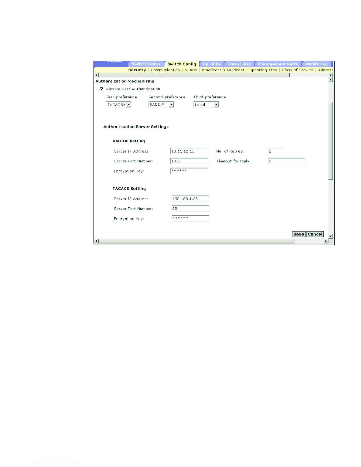
Chapter 3 General Management of the Switch 3-31
FIGURE 3-12 The Switch Config ⇒ Security Window for Use With Authentication Servers
To configure authentication parameters for local access:
1. Type a user name.
2. Select an access level, Normal or Privileged.
3. Type a password.
4. Click Add.
Page 70
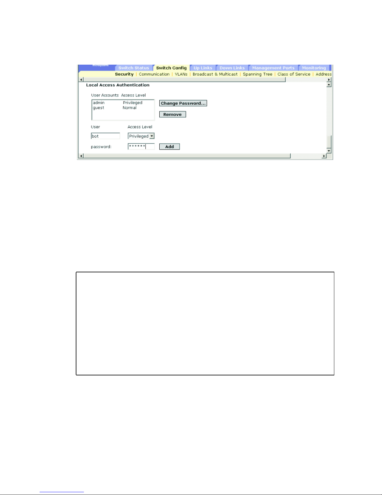
3-32 Sun Fire B1600 Blade System Chassis Switch Administration Guide • June 2003
FIGURE 3-13 The Switch Config ⇒ Security Window Showing Locally Stored Logins
3.2.6.2 Command-line Interface: Configuring User Authentication
1. Assign a user name and access level. Type 0 for Normal access and 15 for
Privileged access.
2. Specify the password.
3. Configure the required settings for RADIUS and TACACS+ remote client
authentication.
Console(config)#username bob access-level 15
Console(config)#username bob password 0 smith
Console(config)#authentication login local tacacs radius
Console(config)#tacacs-server host 192.168.1.24
Console(config)#tacacs-server port 181
Console(config)#tacacs-server key green
Console(config)#radius-server host 192.168.1.25
Console(config)#radius-server port 181
Console(config)#radius-server key white
Console(config)#radius-server retransmit 5
Console(config)#radius-server timeout 10
Console(config)#
Page 71

Chapter 3 General Management of the Switch 3-33
3.2.6.3 MIB variables Associated With User Authentication
3.2.7 Configuring SNMP
The Simple Network Management Protocol (SNMP) is a communication protocol
designed specifically for managing devices or other elements on a network.
TABLE 3-9 MIB Variables Associated With User Authentication
Field Name MIB Variable Access Value Range
Default
Value
User Name Not Defined
Password Not Defined
Access Level Not Defined
Authenticatio
n Sequence
Not Defined
RADIUS
Server
Address
sun...
securityMgt.radiusMgt.
radiusServerAddress
Read/write IP address 10.11.12
.13
RADIUS
Server Port
Number
sun...
securityMgt.radiusMgt.
radiusServerPortNumber
Read/write Integer
(1-65535)
1812
RADIUS
Server
Encryption
Key
sun...
securityMgt.radiusMgt.
radiusServerKey
Read/write
(Read
always
returns 0)
String
(size (0-20))
RADIUS
Server
Retransmit
sun...
securityMgt.radiusMgt.
radiusServerRetransmit
Read/write Integer
(1-65535)
2
RADIUS
Server
Timeout
sun...
securityMgt.radiusMgt.
radiusServerTimeout
Read/write Integer
(1-65535)
seconds
5
TACACS
Server
Address
sun...
securityMgt.tacacsMgt.
tacacsServerAddress
Read/write IP address
TACACS
Server Port
Number
sun...
securityMgt.tacacsMgt.
tacacsServerPortNumber
Read/write Integer
(1-65535)
TACACS
Server
Encryption
Key
sun...
securityMgt.tacacsMgt.
tacacsServerKey
Read/write
(Read
always
returns 0)
String
(size (0-20))
Page 72

3-34 Sun Fire B1600 Blade System Chassis Switch Administration Guide • June 2003
Equipment commonly managed with SNMP includes switches, routers, and host
computers. SNMP is typically used to configure these devices for proper operation
in a network environment, as well as to monitor them to evaluate performance or
detect potential problems.
The blade system chassis switch includes an on-board SNMP agent that
continuously monitors the status of its hardware and the traffic passing through its
ports. A network management station can access this information using software
such as Solstice Domain Manager. Access rights to the on-board agent are controlled
by community strings. To communicate with the switch, the management station
must first submit a valid community string for authentication. The options for
configuring community strings and related trap functions are described in the
following sections.
3.2.7.1
Configuring SNMP Access
You can configure up to five community strings authorized for management access.
For security reasons, consider removing the default strings.
When configuring SNMP community strings using the web interface or CLI, the
following parameters can be configured:
■ Community – A password (between 1 and 32 characters, which is case sensitive)
that permits access to the SNMP protocol. The default community strings are
public (read-only access) and private (read/write access)
■ Access Level
■ Read Only – Read-only access. Authorized management stations are able to
only retrieve MIB objects.
■ Read/Write – Read/write access. Authorized management stations are able to
both retrieve and modify MIB objects.
Web Interface: Adding and Removing Community Strings
1. Open the Switch Config ⇒ Communication window.
2. Type the new community string
in the String text field.
3. Select the access rights from the Access Level pull-down menu.
4. Click Add.
Page 73
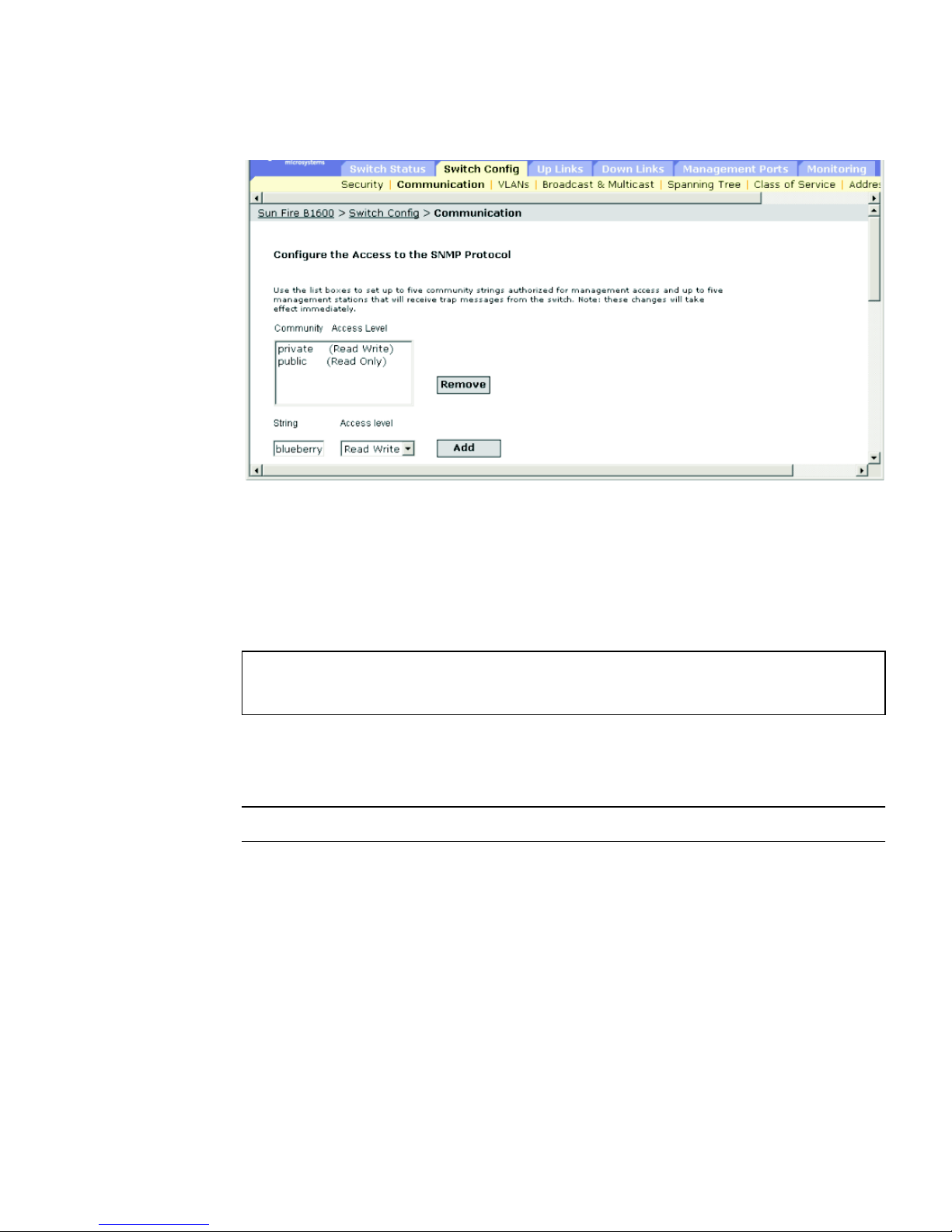
Chapter 3 General Management of the Switch 3-35
FIGURE 3-14 The Switch Config ⇒ Communication Window for Adding and Removing
Community Strings
Command-line Interface: Adding and Removing Community Strings
The following example adds the string blueberry with read/write access.
MIB Variables Associated With Community Strings
Note – There are no MIB variables for these functions.
Console(config)#snmp-server community blueberry rw
Console(config)#
Page 74

3-36 Sun Fire B1600 Blade System Chassis Switch Administration Guide • June 2003
3.2.7.2 Specifying Trap Managers and Trap Types
Traps indicating status changes are issued by the switch to specified trap managers.
You must specify trap managers so that key events are reported by this switch to
your management station (using network management platforms such as Soltice
Domain Manager). You can specify up to five management stations that will receive
trap messages from the switch. The traps supported by this switch are listed under
“Supported Traps” on page A-3.
When configuring SNMP trap managers using the web interface or CLI, the
following parameters can be configured:
■ IP Address – The Internet address of the host (the targeted recipient).
The maximum number of host IP addresses is 5.
■ Community – The password-like string (between 1 and 32 characters) sent with
the notification operation. Although you can set this string in the Trap Managers
table, it is recommended to define this string in the SNMP Protocol table as well.
■ Version – The SNMP version (1 or version 2c) that the host is running.
■ Generate SNMP notification for
■ Port link up and down events – Whenever a port link is established or broken.
■ Authentication traps – Whenever an invalid community string is submitted
during the SNMP access authentication process.
Web Interface: Specifying Trap Management Stations
1. Open the Switch Setup ⇒ Communications window.
2. Type the IP address and community string for each Trap Manager to receive
messages.
3. Click Add.
4. Select Port link up and link down events or Authentication traps if required.
5.
Click Save
.
Page 75
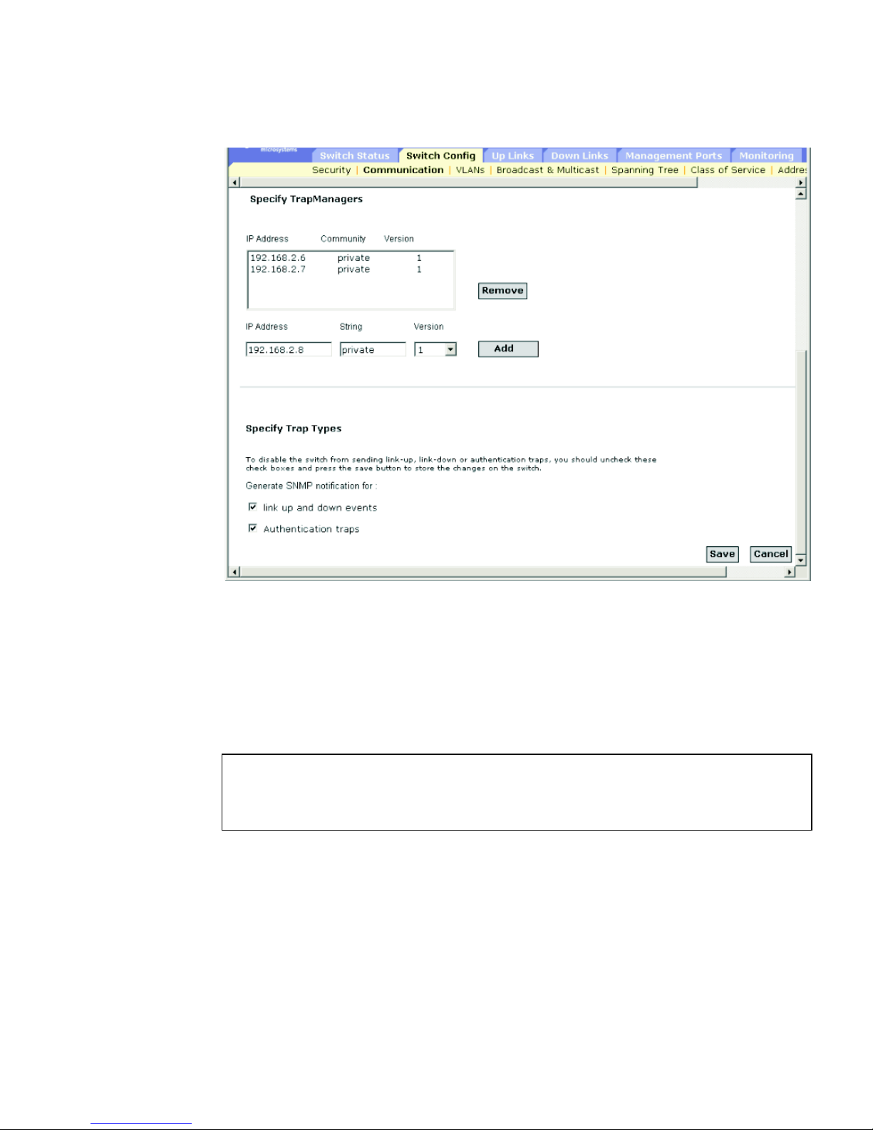
Chapter 3 General Management of the Switch 3-37
FIGURE 3-15 The Switch Config ⇒ Communication Window Listing the Stations That
Receive Traps From the Switch
Command-line Interface: Specifying Trap Management Stations
This example adds a trap manager and enables link-up-down and authentication
traps.
Console(config)#snmp-server host 10.1.0.19 private version 1
Console(config)#snmp-server enable traps link-up-down
Console(config)#snmp-server enable traps authentication
Page 76

3-38 Sun Fire B1600 Blade System Chassis Switch Administration Guide • June 2003
MIB Variables Associated With Trap Management
TABLE 3-10 MIB Variables Associated With Trap Management
Field Name MIB Variable Access Value Range
Default
Value
Trap
Destination
Address
sun...
trapDestMgt.
trapDestTable.
trapDestEntry.
trapDestAddress
No access IP address
Trap
Destination
Community
sun...
trapDestMgt.
trapDestTable.
trapDestEntry.
trapDestCommunity
Read/create String
(size (0-127))
Trap
Destination
Version
sun...
trapDestMgt.
trapDestTable.
trapDestEntry.
trapDestStatus
Read/create version 1 (1),
version 2 (2)
Trap
Destination
Status
sun...
trapDestMgt.
trapDestTable.
trapDestEntry.
trapDestStatus
Read/create valid (1),
invalid (2)
Enable Linkup-down Traps
MIB-II
ifMIB.ifMIBObjects.
ifXTable.ifXEntry.
ifLinkUpDownTrapEna
ble
Read/write enabled (1),
disabled (2)
enabled
Page 77

Chapter 3 General Management of the Switch 3-39
3.3 Configuring Global Network Protocols
This section describes how to configure global switch settings for virtual LANs,
multicast service, Spanning Tree Algorithm, handling data based on specific class-ofservice requirements, and displaying the address table or setting static addresses.
3.3.1 VLAN Configuration
In conventional networks with routers, broadcast traffic is split up into separate
domains. Switches do not inherently support broadcast domains. This can lead to
broadcast storms in large networks that handle traffic such as IPX or NetBEUI. By
using IEEE 802.1Q-compliant VLANs, you can organize any group of network nodes
into separate broadcast domains, thus confining broadcast traffic to the originating
group. This also provides a more secure and efficient network environment.
An IEEE 802.1Q VLAN is a group of ports that can be located anywhere in the
network, but communicate as though they belong to the same physical segment.
VLANs help to simplify network management by allowing you to move devices to a
new VLAN without having to change any physical connections. VLANs can be
organized to reflect departmental groups (such as Marketing or R&D), usage groups
(such as e-mail), or multicast groups (used for multimedia applications such as
videoconferencing).
VLANs provide greater network efficiency by reducing broadcast traffic and enable
you to make network changes without having physically change network
connections. VLANs inherently provide a high level of network security since traffic
must pass through a configured Layer-3 link to reach a different VLAN.
This switch supports the following VLAN features:
■ Up to 255 VLANs based on the IEEE 802.1Q standard
■ Distributed VLAN learning across multiple switches using explicit or implicit
tagging
■ Port overlapping, allowing a port to participate in multiple VLANs
■ End stations can belong to multiple VLANs
■ Passing traffic between VLAN-aware and VLAN-unaware devices
■ Priority tagging
Before enabling VLANs for the switch, you must first assign each port to the VLAN
group(s) in which it will participate. By default all ports are assigned to VLAN 1 as
untagged ports. Add a port as a tagged port if you want it to carry traffic for one or
more VLANs, and any intermediate network devices or the host at the other end of
Page 78

3-40 Sun Fire B1600 Blade System Chassis Switch Administration Guide • June 2003
the connection supports VLANs. Then assign ports on the other VLAN-aware
network devices along the path that will carry this traffic to the same VLAN(s),
either manually or dynamically using GVRP. However, if you want a port on this
switch to participate in one or more VLANs, but none of the intermediate network
devices nor the host at the other end of the connection supports VLANs, then you
should add this port to the VLAN as an untagged port.
Note – VLAN-tagged frames can pass through VLAN-aware or VLAN-unaware
network interconnection devices, but should not be used for any end-node host that
does not support VLAN tagging.
Note these points about assigning ports to VLANs:
■ VLAN Classification – When the switch receives a frame, it classifies the frame in
one of two ways. If the frame is untagged, the switch assigns the frame to an
associated VLAN (based on the PVID of the receiving port). But if the frame is
tagged, the switch uses the tagged VLAN ID to identify the port broadcast
domain of the frame.
■ Port Overlapping – Port overlapping can be used to allow access to commonly
shared network resources among different VLAN groups, such as file servers or
printers. Note that if you implement VLANs which do not overlap, but still need
to communicate, you can connect them by using a Layer-3 router or switch.
■ Port-based VLANs – Port-based (or static) VLANs are manually tied to specific
ports. The switch’s forwarding decision is based on the destination MAC address
and its associated port. Therefore, to make valid forwarding or flooding decisions,
the switch must learn the relationship of the MAC address to its related
port—and thus to the VLAN—at run-time. However, when GVRP is enabled, this
process can be fully automatic.
■ Automatic VLAN Registration – GARP VLAN Registration Protocol (GVRP)
defines a system whereby the switch can automatically learn the VLANs to which
each end station should be assigned. If an end station (or its network adapter)
supports the IEEE 802.1Q VLAN protocol, it can be configured to broadcast a
message to your network indicating the VLAN groups it wants to join. When this
switch receives these messages, it will automatically place the receiving port in
the specified VLANs, and then forward the message to all other ports. When the
message arrives at another switch that supports GVRP, it will also place the
receiving port in the specified VLANs, and pass the message on to all other ports.
VLAN requirements are propagated in this way throughout the network. This
allows GVRP-compliant devices to be automatically configured for VLAN groups
based solely on end-station requests.
To implement GVRP in a network, first add the host devices to the required
VLANs (using the operating system or other application software), so that these
VLANs can be propagated onto the network. For both the edge switches attached
directly to these hosts, and core switches in the network, enable GVRP on the
links between these devices. (See “Configuring VLAN Behavior for Interfaces” on
Page 79

Chapter 3 General Management of the Switch 3-41
page 3-114.) You should also determine security boundaries in the network and
disable GVRP on end-station ports where you need to prevent advertisements
from being propagated, or forbid ports from joining restricted VLANs.
Note – If you have host devices that do not support GVRP, you must configure
static VLANs for the switch ports connected to these devices (as described in
“Adding Static Members to VLANs” on page 3-50). But you still need to enable
GVRP on these edge switches, as well as on the core switches in the network.
■ If you want to create a small port-based VLAN for devices attached directly to a
single switch, you can assign ports to the same untagged VLAN. However, to
participate in a VLAN group that crosses several switches, you need to create a
VLAN for that group and enable tagging on all ports.
Ports can be assigned to multiple tagged or untagged VLANs. Each port on the
switch is therefore capable of passing tagged or untagged frames. When
forwarding a frame from this switch along a path that contains any VLAN-aware
devices, the switch should include VLAN tags. When forwarding a frame from
this switch along a path that does not contain any VLAN-aware devices
(including the destination host), the switch must first strip off the VLAN tag
before forwarding the frame. When the switch receives a tagged frame, it will
pass this frame onto the VLAN(s) indicated by the frame tag. However, when this
switch receives an untagged frame from a VLAN-unaware device, it first decides
where to forward the frame, and then inserts a VLAN tag reflecting the ingress
port’s default VID.
3.3.1.1 Displaying Basic VLAN Information
When displaying basic VLAN information using the web interface or CLI, the
following parameters are displayed:
■ VLAN Version Number – The VLAN version used by this switch as specified in
the IEEE 802.1Q standard.
■ Maximum VLAN ID – The maximum VLAN ID recognized by this switch.
■ Maximum Number of Supported VLANs – The maximum number of VLANs that
can be configured on this switch.
Web Interface: Displaying Basic VLAN Information
● Open the Switch Config ⇒ VLANs window.
Page 80
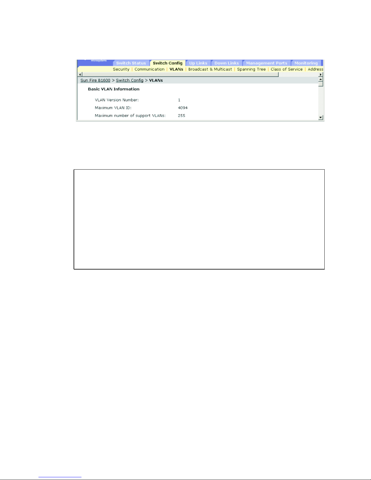
3-42 Sun Fire B1600 Blade System Chassis Switch Administration Guide • June 2003
Command-line Interface: Displaying Basic VLAN Information
● Type the following command:
Console#show bridge-ext
Max support vlan numbers: 32
Max support vlan ID: 4094
Extended multicast filtering services: No
Static entry individual port: Yes
VLAN learning: IVL
Configurable PVID tagging: Yes
Local VLAN capable: Yes
Traffic classes: Enabled
Global GVRP status: Disabled
GMRP: Disabled
Console#
Page 81

Chapter 3 General Management of the Switch 3-43
MIB Variables Associated With Basic VLAN Information
TABLE 3-11 MIB Variables Associated With Basic VLAN Information
Field Name MIB Variable Access Value Range
Default
Value
VLAN
Version
Number
MIB-II.
dot1dBridge.
qBridgeMIB.
qBridgeMIBObjects
.
dot1qBase.
dot1qVlanVersionNumber
Read only version1 (1) version1
Maximum
VLAN ID
MIB-II.
dot1dBridge.
BridgeMIB.
BridgeMIBObjects.
dot1qBase.
dot1qMaxVlanId
Read only Integer 4094
Maximum
Number of
Supported
VLANs
MIB-II.
dot1dBridge.
qBridgeMIB.
qBridgeMIBObjects
.
dot1qBase.
dot1qMaxSupportedV
lans
Read only Integer 255
Device
Capabilities
MIB-II.
dot1dBridge.
pBridgeMIB.
pBridgeMIBObjects
.
dot1dExtBase.
dot1dDeviceCapabi
lities
Read only Bit String –
ExtendedFiltering
dot1dServices (0),
dot1dTrafficClasses
(1),
StaticEntry
dot1dIndividualPort
(2),
dot1dIVLCapable (3),
dot1dSVLCapable (4),
dot1dHybridCapable
(5),
dot1dConfigurablePvi
d
dot1dTagging (6),
2, 3, 6, 7
dot1dLocalVlanCapable (7)
Page 82

3-44 Sun Fire B1600 Blade System Chassis Switch Administration Guide • June 2003
Traffic
Classes
Enabled
MIB-II.
dot1dBridge.
pBridgeMIB.
pBridgeMIBObjects.
dot1dExtBase.
dot1dTrafficClassesEnabled
Read/
write
true (1),
false (2)
true
GMRP Status MIB-II.
dot1dBridge.
pBridgeMIB.
pBridgeMIBObjects.
dot1dExtBase.
dot1dGmrpStatus
Read/
write
enabled (1),
disabled (2)
disabled
GVRP Status MIB-II.
dot1dBridge.
qBridgeMIB.
qBridgeMIBObjects.
dot1qBase.
dot1qGvrpStatus
Read/
write
enabled (1),
disabled (2)
disabled
TABLE 3-11 MIB Variables Associated With Basic VLAN Information (Continued)
Field Name MIB Variable Access Value Range
Default
Value
Page 83
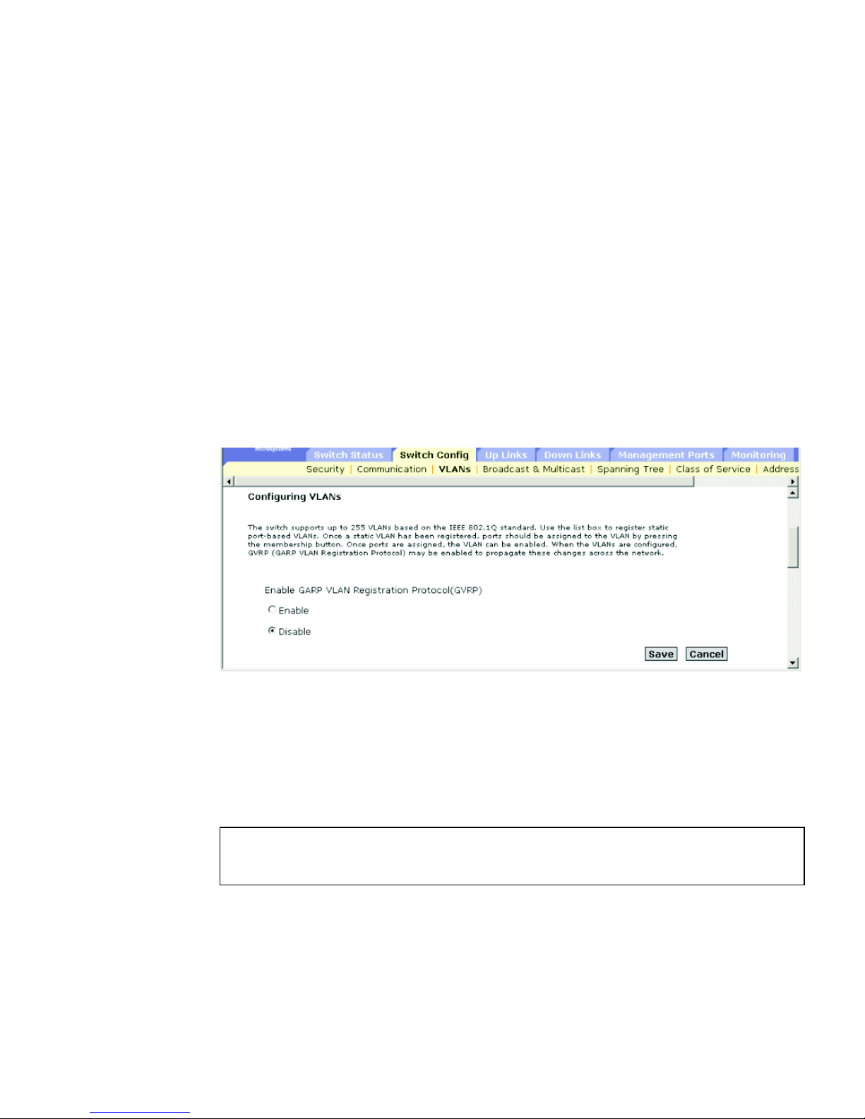
Chapter 3 General Management of the Switch 3-45
3.3.1.2 Enabling or Disabling GVRP (Global Setting)
GARP VLAN Registration Protocol (GVRP) defines a way for switches to exchange
VLAN information in order to register VLAN members on ports across the network.
VLANs are dynamically configured based on join messages issued by host devices
and propagated throughout the network. GVRP must be enabled to permit automatic
VLAN registration, and to support VLANs which extend beyond the local switch.
Web Interface: Enabling or Disabling GVRP (Global Setting)
1. Open Switch Config ⇒ VLANs.
2. Select Enable or Disable.
3. Click Save.
FIGURE 3-16 The Switch Config ⇒ VLANs Window (showing radio buttons for enabling
GVRP)
Command-line Interface: Enabling GVRP
Th following sample command enables GVRP for the switch:
Console(config)#bridge-ext gvrp
Console(config)#
Page 84

3-46 Sun Fire B1600 Blade System Chassis Switch Administration Guide • June 2003
MIB Variables Associated With GVRP
3.3.1.3 Configuring VLANs
When configuring VLANs using the web interface or CLI, the following parameters
are displayed or can be configured:
■ ID – The ID of configured VLAN (1 to 4094).
■ Name – The name of the VLAN (1 to 15 characters).
■ Status – The current operational state of the VLAN.
■ Enable (Active
9
) – The VLAN is active.
■ Disable (Suspend
9
) – The VLAN is suspended; that is, it does not pass packets.
■ Creation Type – The method by which the VLAN was added to the switch.
■ Dynamic GVRP (Dynamic
9
): Automatically learned through GVRP.
■ Permanent (Static
9
): Manually configured as a static entry.
■ Ports / Channel groups
9
– The interfaces that are members of the VLAN.
Web Interface: Configuring VLANs
To create a new VLAN, follow these steps:
1. Open Switch Config
⇒ VLANs.
2. Type the new VLAN ID and name.
3. Set the status to Enabled or Disabled.
4. Click Add.
To modify existing VLANs:
1. Select one or more entries.
TABLE 3-12 MIB Variables Associated With GVRP
Field Name MIB Variable Access Value Range
Default
Value
GVRP Status MIB-II.
dot1dBridge.
qBridgeMIB.
qBridgeMIBObjects
.
dot1qBase.
dot1qGvrpStatus
Read/write enabled (1),
disabled (2)
disabled
9. CLI displaysthese terms.
Page 85
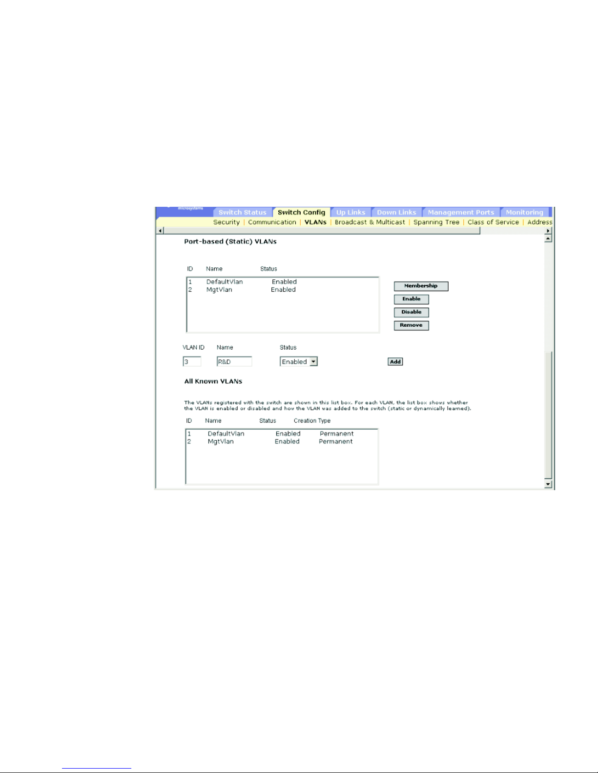
Chapter 3 General Management of the Switch 3-47
2. Click Enable, Disable or Remove.
To add interfaces to a VLAN:
1. Select an
entry.
2. Click Membership.
(See “Adding Static Members to VLANs” on page 3-50.)
FIGURE 3-17 The Switch Config ⇒ VLANs Window With the Default VLAN Configuration
Displayed
Page 86

3-48 Sun Fire B1600 Blade System Chassis Switch Administration Guide • June 2003
Command-line Interface: VLAN Configuration
The following sample commands create a new VLAN and display all VLAN
information:
Console(config)#vlan database
Console(config-vlan)#vlan 3 name R&D media ethernet state active
Console(config-vlan)#
Console#show vlan
VLAN Type Name Status Ports/Channel groups
---- ------- ---------------- --------- --------------------------------------- 1 Static DefaultVlan Active SNP0 SNP1 SNP2 SNP3 SNP4
SNP5 SNP6 SNP7 SNP8 SNP9
SNP10 SNP11 SNP12 SNP13 SNP14
SNP15 NETP0 NETP1 NETP2 NETP3
NETP4 NETP5 NETP6 NETP7
2 Static MgtVlan Active NETMGT
3 Static R&D Active
Console#
Page 87

Chapter 3 General Management of the Switch 3-49
MIB Variables Associated With VLAN Configuration
TABLE 3-13 MIB Variables Associated With VLAN Configuration
Field Name MIB Variable Access Value Range
Default
Value
VLAN ID MIB-
II.dot1dBridge.
qBridgeMIB.
qBridgeMIBObjects
.
dot1qVlan.
dot1qVlanCurrentT
able.
dot1qVlanCurrentE
ntry.
dot1qVlanIndex
No access Integer 1
VLAN Name MIB-
II.dot1dBridge.
qBridgeMIB.
qBridgeMIBObjects
.
dot1qVlan.
dot1qVlanStaticTa
ble.
dot1qVlanStaticEn
try.
dot1qVlanStaticNa
me
Read/
create
Octet string
(size (0-32))
VLAN Status MIB-
II.dot1dBridge.
qBridgeMIB.
qBridgeMIBObjects
.
dot1qVlan.
dot1qVlanStaticTa
ble.
dot1qVlanStaticEn
try.
dot1qVlanStatic.
RowStatus
Read/
create
enable(1),
disable(2)
Page 88

3-50 Sun Fire B1600 Blade System Chassis Switch Administration Guide • June 2003
3.3.1.4 Adding Static Members to VLANs
When adding static members to VLANs using the web interface or CLI, the
following parameters are displayed or can be configured:
■ Name – The name of the VLAN.
■ Up Time at Creation – The time the VLAN was created.
■ Status
10
– The method by which the VLAN was added to the switch.
■ Dynamic: Automatically learned through GVRP.
■ Static: Manually configured as a static entry.
■ All Ports – The port or port-channel identifier.
■ Membership Ports – The interfaces added to the selected VLAN as tagged or
untagged, or restricted from being automatically added through GVRP.
■ Membership Type – Specify VLAN membership by highlighting the required
interface, and clicking the appropriate Add button:
VLAN Type MIB-
II.dot1dBridge.
qBridgeMIB.
qBridgeMIBObjects
.
dot1qVlan.
dot1qVlanCurrentT
able.
dot1qVlanCurrentE
ntry.
dot1qVlanStatus
Read only other(1),
permanent(2),
dynamicGvrp(3)
VLAN Ports MIB-
II.dot1dBridge.
qBridgeMIB.
qBridgeMIBObjects
.
dot1qVlan.
dot1qVlanCurrentT
able.
dot1qVlanCurrentE
ntry.
dot1qVlanCurrentEgressPorts
Read only Octet string
(port list)
10.CLI only.
TABLE 3-13
MIB Variables Associated With VLAN Configuration (Continued)
Field Name MIB Variable Access Value Range
Default
Value
Page 89

Chapter 3 General Management of the Switch 3-51
■ Add Tagged: The interface is a member of the VLAN. All packets transmitted
by the port on this VLAN will be tagged, that is, carry a tag and therefore carry
VLAN or COS information.
■ Add Untagged: The interface is a member of the VLAN. All packets
transmitted by the port will be untagged, that is, not carry a tag and therefore
not carry VLAN or COS information.
■ Add Forbidden: The interface is forbidden from automatically joining the
VLAN through GVRP. See “Automatic VLAN Registration” on page 3-40.
■ Remove: Removes the selected interface from the VLAN.
Web Interface: Adding Ports Manually to a VLAN
To add an interface to a VLAN:
1. Open Switch Config
⇒ VLANs.
2. Highlight a VLAN in the static list, and click Membership.
3. From the port membership page, select an interface from the All Ports list (port or
port-channel).
4. Click Add Tagged, Add Untagged, or Add Forbidden (to prevent this interface
from being added through GVRP).
To remove an interface from a VLAN:
1. Select an entry from the Membership Ports list.
2. Click Remove.
Page 90
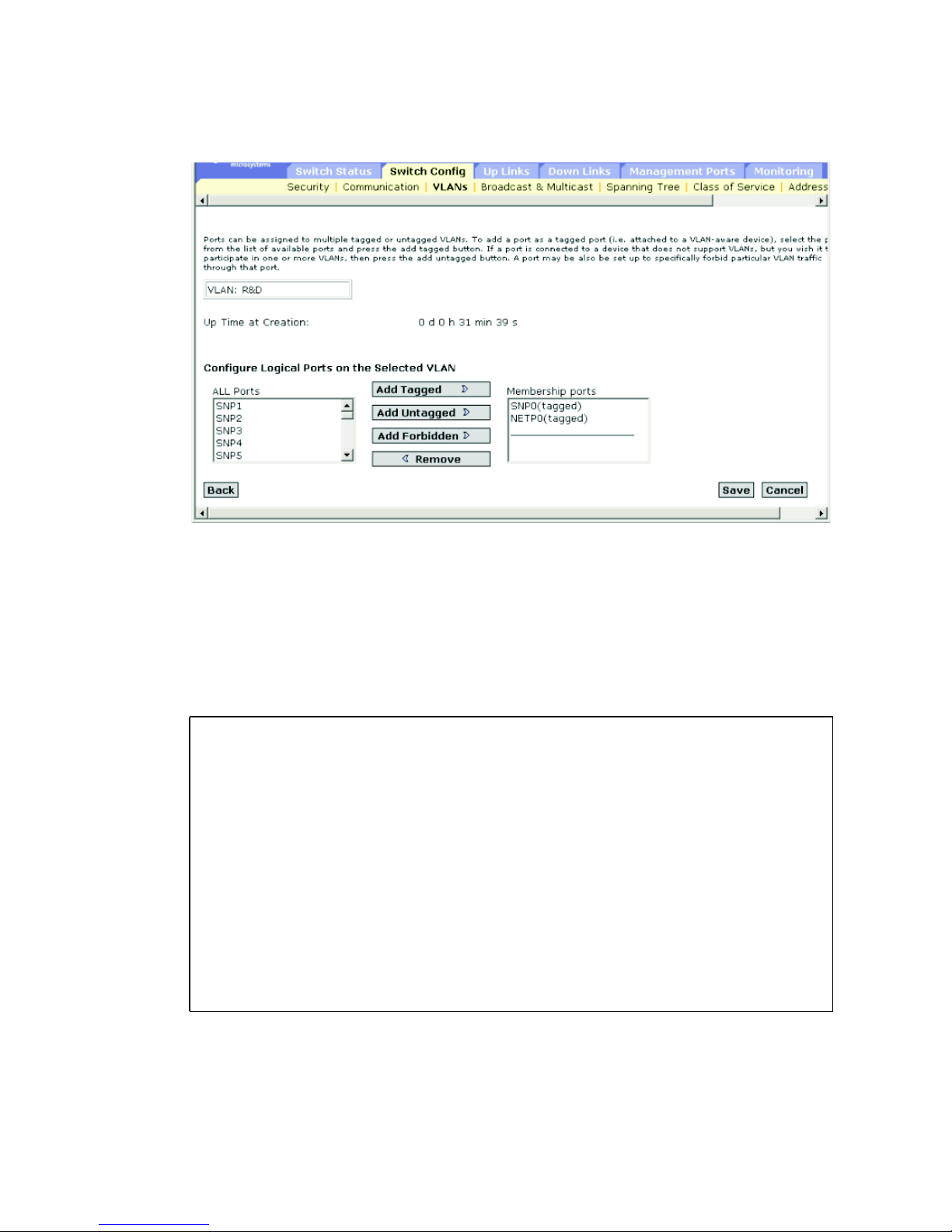
3-52 Sun Fire B1600 Blade System Chassis Switch Administration Guide • June 2003
FIGURE 3-18 The Switch Config ⇒ VLANs Window
Command-line Interface: Adding Ports Manually to a VLAN
The following example adds two ports to VLAN 3 (named R&D), forbids server
blade port SNP13 from joining the VLAN dynamically (using GVRP), and finally
displays the VLAN’s membership:
Console(config)#interface ethernet NETP1
Console(config-if)#switchport allowed vlan add 3 tagged
Console(config-if)#exit
Console(config)#interface ethernet NETP2
Console(config-if)#switchport allowed vlan add 3 untagged
Console(config-if)#exit
Console(config)#interface ethernet SNP13
Console(config-if)#switchport forbidden vlan add 3
Console(config-if)#end
Console#show vlan id 3
VLAN Type Name Status Ports/Channel groups
---- ------- ---------------- --------- ------------------------ 3 Static R&D Active NETP1 NETP2
Console#
Page 91

Chapter 3 General Management of the Switch 3-53
MIB Variables Associated With Adding Ports to a VLAN
TABLE 3-14 MIB Variables Associated With Adding Ports to a VLAN
Field Name MIB Variable Access Value Range Default Value
VLAN ID MIB-II.
dot1dBridge.
qBridgeMIB.
qBridgeMIBObjects.
dot1qVlan.
dot1qVlanStaticTable.
dot1qVlanStaticEntry.
dot1qVlanIndex
Index Row
VLAN Name MIB-II.
dot1dBridge.
qBridgeMIB.
qBridgeMIBObjects.
dot1qVlan.
dot1qVlanStaticTable.
dot1qVlanStaticEntry.
dot1qVlanStaticName
Read/create Octet string
(size (0-32))
Up Time at
Creation
MIB-II.
dot1dBridge.
qBridgeMIB.
qBridgeMIBObjects.
dot1qVlan.
dot1qVlanCurrentTable.
dot1qVlanCurrentEntry.
dot1qVlanCreationTime
Read only Timeticks
(in centiseconds)
VLAN Status MIB-II.
dot1dBridge.
qBridgeMIB.
qBridgeMIBObjects.
dot1qVlan.
dot1qVlanCurrentTable.
dot1qVlanCurrentEntry.
dot1qVlanStatus
Read only other(1),
permanent(2),
dynamicGvrp(3)
Tagged Ports,
Untagged Ports
(Allowed VLAN)
MIB-II.
dot1dBridge.
qBridgeMIB.
qBridgeMIBObjects.
dot1qVlan.
dot1qVlanTable.
dot1qVlanEntry.
dot1qVlanStaticUntaggedPorts
Read/create Octet string
(port list)
Page 92

3-54 Sun Fire B1600 Blade System Chassis Switch Administration Guide • June 2003
3.3.2 Multicast Configuration
Multicasting is used to support real-time applications such as videoconferencing or
streaming audio. A multicast server does not have to establish a separate connection
with each client. It merely broadcasts its service to the network and any hosts that
want to receive the multicast service register with their local multicast switch/
router. Although this approach reduces the network overhead required by a
multicast server, the broadcast traffic must be carefully pruned at every multicast
switch/router it passes through to ensure that traffic is only passed on to the hosts
that subscribed to the service.
The blade system chassis switch uses the Internet Group Management Protocol
(IGMP) to query for any attached hosts that want to receive a specific multicast
service. It identifies the ports containing hosts requesting to join the service and
sends data out to those ports only. It then propagates the service request up to any
neighboring multicast switch/router to ensure that it will continue to receive the
multicast service. This procedure is called multicast filtering.
VLAN
Forbidden Ports
MIB-II.
dot1dBridge.
qBridgeMIB.
qBridgeMIBObjects.
dot1qVlan.
dot1qPortVlanTable.
dot1qPortVlanEntry.
dot1qVlanForbiddenEgressPorts
Read/create Octet string
(port list)
Port Trunk Index
(Channel
Groups)
sun...
portMgt.
portTable
portEntry.
portTrunkIndex
Read only Integer
VLAN Static
Row Status
MIB-II.
dot1dBridge.
qBridgeMIB.
qBridgeMIBObjects.
dot1qVlan.
dot1qVlanStaticTable.
dot1qVlanStaticEntry.
dot1qVlanStaticRowStatus
Read/create enable(1),
disable(2)
TABLE 3-14 MIB Variables Associated With Adding Ports to a VLAN (Continued)
Field Name MIB Variable Access Value Range Default Value
Page 93

Chapter 3 General Management of the Switch 3-55
The purpose of IP multicast filtering is to optimize a switched network’s
performance, so that multicast packets will only be forwarded to those ports
containing multicast group hosts or multicast routers/switches, instead of flooding
traffic to all ports in the subnet (VLAN).
3.3.2.1 Configuring IGMP Snooping Parameters
You can configure the switch to forward multicast traffic intelligently. Based on the
IGMP query and report messages, the switch forwards traffic only to the ports that
request multicast traffic. This prevents the switch from broadcasting the traffic to all
ports and possibly disrupting network performance.
Note the following points about IGMP snooping:
■ IGMP Snooping – The switch can passively snoop on IGMP Query and Report
packets transferred between IP multicast routers/switches and IP multicast host
groups to identify the IP multicast group members. It monitors the IGMP packets
passing through it, picks out the group registration information, and configures
multicast filters accordingly.
■ IGMP Querier – A router, or multicast-enabled switch, can periodically ask their
hosts if they want to receive multicast traffic. If there is more than one router/
switch on the LAN performing IP multicasting, one of these devices is elected
“querier” and assumes the role of querying the LAN for group members. It then
propagates the service requests on to any upstream multicast switch/router to
ensure that it will continue to receive the multicast service.
Note – Multicast routers use this information, along with a multicast routing
protocol such as DVMRP, to support IP multicasting across the Internet.
When configuring IGMP snooping through the web interface or CLI, the following
parameters are displayed or can be configured:
■ IGMP Snooping – The operating status of IGMP. When enabled, the switch will
monitor network traffic to determine which hosts want to receive multicast traffic.
The default is Disabled.
■ IGMP Protocol Version – The protocol version. Specify 1 or 2 for compatibility
with other devices on the network. The default is 2.
■ IGMP Querier – The operating status of IGMP querier. When enabled, the switch
can serve as the querier, which is responsible for asking hosts if they want to
receive multicast traffic. The default is Disabled.
■ Query Count – The maximum number of queries issued (between 2 and 10) for
which there has been no response before the querier takes action to drop a
client from the multicast group. The default is 2.
Page 94

3-56 Sun Fire B1600 Blade System Chassis Switch Administration Guide • June 2003
■ Query Interval – The frequency (between 60 and 125 seconds) at which the
switch sends IGMP host-query messages. The default is 125 seconds.
■ Query Report Delay – The time (between 5 and 25 seconds) between receiving
an IGMP Report for an IP multicast address on a port before the switch sends
an IGMP Query out of that port and removes the entry from its list. The default
is 10 seconds.
■ Router Port Expire Time – The time (between 300 and 500 seconds) the switch
waits after the previous querier stops querying before it determines that the
interface (which had been receiving query packets) is no longer attached to a
querier. The default is 300 seconds.
Note – All systems on the subnet must support the same version.
Some attributes are only enabled for IGMPv2, including IGMP Report Delay
and Router Port Expire Time.
Web Interface: Configuring IGMP Snooping Parameters
1. Open Switch Config ⇒ Broadcast & Multicast ⇒ IGMP Parameters.
2. Adjust the IGMP settings as required.
3. Click Save.
Page 95
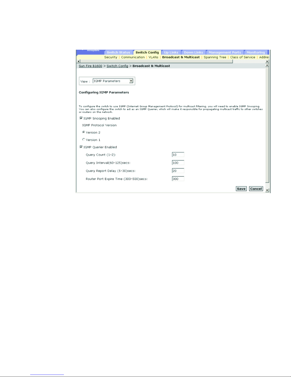
Chapter 3 General Management of the Switch 3-57
FIGURE 3-19 The Switch Config ⇒ Broadcast & Multicast Window
Page 96

3-58 Sun Fire B1600 Blade System Chassis Switch Administration Guide • June 2003
Command-line Interface: Configuring IGMP Snooping Parameters
This example modifies the settings for multicast filtering, and then displays the
current status.
Console(config)#ip igmp snooping
Console(config)#ip igmp snooping querier
Console(config)#ip igmp snooping query-count 10
Console(config)#ip igmp snooping query-interval 100
Console(config)#ip igmp snooping query-max-response-time 20
Console(config)#ip igmp router-port-expire-time 300
Console(config)#ip igmp snooping version 2
Console(config)#exit
Console#show ip igmp snooping
Igmp Snooping Configuration
--------------------------------------------- Service status : Enabled
Querier status : Enabled
Query count : 10
Query interval : 100 sec
Query max response time : 20 sec
Query time-out : 300 sec
IGMP snooping version : Version 2
Console#
Page 97

Chapter 3 General Management of the Switch 3-59
MIB Variables Associated With IGMP Parameters
3.3.2.2 Specifying Interfaces Connected to Multicast Routers
Multicast routers use the information obtained from IGMP Query, along with a
multicast routing protocol such as DVMRP, to support IP multicasting across the
Internet. These routers may be dynamically discovered by the switch or statically
assigned to an interface on the switch.
Depending on your network connections, IGMP snooping may not always be able to
locate the IGMP querier. Therefore, if the IGMP querier is a known multicast router/
switch connected over the network to an interface (port or aggregated link) on your
switch, you can manually configure the interface (and a specified VLAN) to join all
the current multicast groups supported by the connected router. This can ensure that
multicast traffic is passed on to all the appropriate interfaces within the switch.
TABLE 3-15 MIB Variables Associated With IGMP Parameters
Field Name MIB Variable Access Value Range Default Value
Snooping
Status
sun...
igmpSnoopMgt.
igmpSnoopStatus
Read/write enabled (1),
disabled (2)
enabled
Snooping
Querier
sun...
igmpSnoopMgt.
igmpSnoopQuerier
Read/write enabled (1),
disabled (2)
enabled
Snooping
Query Count
sun...
igmpSnoopMgt.
igmpSnoopQueryCount
Read/write Integer (2-10) 2
Snooping
Query Interval
sun...
igmpSnoopMgt.
igmpSnoopQueryInterval
Read/write Integer (60-125)
seconds
125
Snooping
Query Max
Response Time
sun...
igmpSnoopMgt.
igmpSnoopQueryMaxResponseTime
Read/write Integer (5-25)
seconds
10
Snooping
Router Port
Expire Time
sun...
igmpSnoopMgt.
igmpSnoopRouterPort
-ExpireTime
Read/write Integer (300-500)
seconds
300
Snooping
Version
sun...
igmpSnoopMgt.
igmpSnoopVersion
Read/write Integer (1-2) 2
Page 98

3-60 Sun Fire B1600 Blade System Chassis Switch Administration Guide • June 2003
When specifying interfaces connected to multicast routers through the web interface
or CLI, the following parameters are displayed or can be configured:
■ All known ports in VLAN connected to multicast routers:
■ VLAN – The VLAN on the switch.
(The pull-down menu includes the VLAN ID and name.)
■ Interface – The interfaces connected to a multicast router and the whether the
assignment was static (Static) or dynamic (IGMP).
■ Ports in the VLAN statically connected to multicast routers:
■ Available Ports – The interfaces that have not been assigned to the selected
VLAN as multicast router ports.
■ Current Static Ports – The interfaces that have already been assigned to the
selected VLAN as multicast router ports.
Web Interface: Specifying Interfaces Connected to Multicast Routers
1. Open Switch Config ⇒ Broadcast & Multicas ⇒ Multicast Router Ports.
2. Select a VLAN.
3. Click Query to display all the interfaces in the VLAN that are connected to
multicast routers.
4. From the Available Ports, select an interface that is connected to a multicast router
5. Click Add.
6. From Current Static Ports, select an interface that is no longer connected to a
multicast router.
7. Click Remove.
Page 99
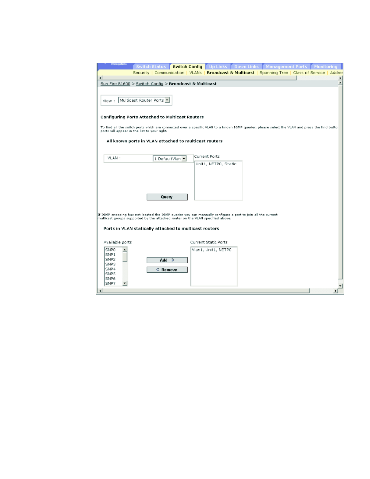
Chapter 3 General Management of the Switch 3-61
FIGURE 3-20 The Switch Config ⇒ Broadcast & Multicast Window (Multicast Router Ports
selected)
Page 100

3-62 Sun Fire B1600 Blade System Chassis Switch Administration Guide • June 2003
Command-line Interface: Specifying Interfaces Connected to Multicast
Routers
The following example configures port NETP0 as a multicast router port within
VLAN 1 and then displays a confirmation of this configuration:
MIB Variables Associated With Interfaces Connected to Multicast
Routers
Console(config)#ip igmp snooping vlan 1 mrouter ethernet NETP0
Console(config)#exit
Console#show ip igmp snooping mrouter vlan 1
VLAN M'cast Router Port Type
---- ------------------ ------ 1 NETP0 Static
TABLE 3-16 MIB Variables Associated With Interfaces Connected to Multicast Routers
Field Name MIB Variable Access Value Range
Snooping
Multicast Router
Current VLAN
sun...
igmpSnoopMgt.
igmpSnoopRouterCurrentTable.
igmpSnoopRouterCurrentEntry.
dot1qVlanIndex
Index Integer
VLAN Name MIB-II.
dot1dBridge.
qBridgeMIB.
qBridgeMIBObjects.
dot1qVlan.
dot1qVlanStaticTable.
dot1qVlanStaticEntry.
dot1qVlanStaticName
Read/create Octet string
(size (0-32))
Snooping
Multicast Router
Current Ports
sun...
igmpSnoopMgt.
igmpSnoopRouterCurrentTable.
igmpSnoopRouterCurrentEntry.
igmpSnoopRouterCurrentPorts
Read only Octet string
(port list)
Snooping
Multicast Router
Static Vlan Index
sun...
igmpSnoopMgt.
igmpSnoopRouterStaticTable.
igmpSnoopRouterStaticEntry.
dot1qVlanIndex
Index Integer
 Loading...