

Sun Microsystems Sun Fire 6800, Sun Fire 4810, Sun Fire 4800, Sun Fire 3800 Administration Manual
Page 1

Sun Fire™6800/4810/4800/3800
Systems Platform
Administration Manual
Sun Microsystems, Inc.
901 San Antonio Road
Palo Alto, CA 94303 U.S.A.
650-960-1300
Part No. 816-2970-10
May 2002, Revision A
Send comments about this document to: [email protected]
Page 2

Copyright 2002Sun Microsystems,Inc., 4150Network Circle, Santa Clara, CA 95054 U.S.A. All rights reserved.
This product or document is protected by copyright and distributed under licenses restrictingitsuse, copying, distribution, and decompilation.
No part of this product or document may be reproduced in any form byany means without prior written authorization of Sun and its licensors,
if any. Third-party software, including font technology,is copyrighted andlicensed from Sun suppliers.
Parts of the product may be derived from Berkeley BSD systems, licensed fromtheUniversity of California. UNIX is a registeredtrademark in
the U.S. and other countries, exclusively licensed through X/Open Company,Ltd.
Sun, Sun Microsystems, the Sun logo, docs.sun.com, Sun Fire, OpenBoot, Sun StorEdge, andSolaris are trademarks, registered trademarks, or
service marks of Sun Microsystems, Inc. in the U.S. and other countries.All SPARCtrademarks are used under license and are trademarks or
registeredtrademarks of SPARCInternational, Inc. in the U.S. and other countries. ProductsbearingSPARC trademarks are based upon an
architecturedeveloped by Sun Microsystems, Inc.
Federal Acquisitions Commercial Software-Government Users Subject to StandardLicenseTerms and Conditions.
DOCUMENTATIONIS PROVIDED “AS IS” AND ALL EXPRESS OR IMPLIED CONDITIONS, REPRESENTATIONSAND WARRANTIES,
INCLUDING ANY IMPLIED WARRANTY OF MERCHANTABILITY, FITNESS FOR A PARTICULAR PURPOSE OR NONINFRINGEMENT, ARE DISCLAIMED, EXCEPT TO THE EXTENT THAT SUCH DISCLAIMERS ARE HELD TO BE LEGALLY INVALID.
Copyright 2002 Sun Microsystems, Inc., 4150 Network Circle, Santa Clara, CA 95054 Etats-Unis.Tous droits réservés.
Ce produit ou document est protégé par uncopyright et distribué avec deslicences qui en restreignent l’utilisation, la copie, la distribution, et la
décompilation. Aucune partie de ce produitou document ne peut être reproduite sous aucune forme, par quelque moyen que ce soit, sans
l’autorisation préalable et écrite de Sun et de ses bailleurs delicence, s’il y en a. Le logiciel détenu par des tiers, et qui comprend la technologie
relativeaux polices de caractères, est protégé par uncopyright et licencié par des fournisseurs de Sun.
Des parties de ce produit pourront être dérivées dessystèmes Berkeley BSD licenciés parl’Université de Californie. UNIX est une marque
déposée aux Etats-Unis et dans d’autrespays et licenciée exclusivement par X/OpenCompany,Ltd.
Sun, Sun Microsystems, the Sun logo, docs.sun.com, Sun Fire, OpenBoot, Sun StorEdge, etSolaris sont des marques de fabrique ou des marques
déposées, ou marques de service, de Sun Microsystems, Inc. aux Etats-Unis et dansd’autrespays. Toutesles marques SPARCsont utilisées sous
licence et sont des marques de fabrique ou des marques déposées de SPARC International, Inc. aux Etats-Unis etdans d’autres pays. Les
produitsportant les marques SPARCsont basés surune architecturedéveloppée par Sun Microsystems, Inc.
L’interfaced’utilisation graphique OPEN LOOK et Sun™ a été développéepar Sun Microsystems, Inc. pour ses utilisateurs et licenciés. Sun
reconnaîtles efforts de pionniers de Xerox pour larechercheetle développement du concept des interfaces d’utilisation visuelle ou graphique
pour l’industrie de l’informatique. Sun détient une licence non exclusive deXeroxsur l’interface d’utilisation graphique Xerox, cette licence
couvrant également les licenciés de Sun qui mettent en place l’interfaced’utilisation graphique OPEN LOOK etqui en outre se conforment aux
licences écrites de Sun.
LA DOCUMENTATION EST FOURNIE “EN L’ETAT” ET TOUTES AUTRES CONDITIONS, DECLARATIONS ET GARANTIES
EXPRESSES OU TACITESSONT FORMELLEMENT EXCLUES, DANS LA MESURE AUTORISEE PAR LA LOI APPLICABLE, Y COMPRIS
NOTAMMENT TOUTE GARANTIE IMPLICITE RELATIVE A LA QUALITE MARCHANDE, A L’APTITUDE A UNE UTILISATION
PARTICULIERE OU A L’ABSENCE DE CONTREFAÇON.
Please
Recycle
Page 3

Contents
Preface xv
1. Introduction 1
Domains 2
System Components 3
Partitions 3
System Controller 8
Serial and Ethernet Ports 9
System Controller Logical Connection Limits 9
System Controller Software 10
Redundant Components and Minimum Configurations 13
Redundant System Controller Boards 13
CPU/Memory Boards 14
I/O Assemblies 15
Redundant Cooling 16
Redundant Power 17
Repeater Boards 18
Redundant System Clocks 19
Reliability, Availability, and Serviceability (RAS) 20
i
Page 4

Reliability 20
Availability 22
Serviceability 23
Dynamic Reconfiguration Software 24
Sun Management Center Software for the Sun Fire 6800/4810/4800/3800 Systems
Software 25
FrameManager 25
2. System Controller Navigation Procedures 27
Connection to the System Controller 28
Obtaining the Platform Shell 28
▼ To Obtain the Platform Shell Using telnet 28
Obtaining a Domain Shell or Console 30
System Controller Navigation 32
▼ To Enter the Domain Console From the Domain Shell If the Domain Is
Inactive 35
▼ To Enter the Domain Shell From the Domain Console 36
▼ To Get Back to the Domain Console From the Domain Shell 36
▼ To Enter a Domain From the Platform Shell 37
Terminating Sessions 37
▼ To Terminate an Ethernet Connection With telnet 37
▼ To Terminate a Serial Connection With tip 38
3. System Power On and Setup 41
Installing, Cabling, and Powering on the Hardware 43
Setting Up Additional Services Before System Power On 43
Powering On the Hardware 45
Powering On the Power Grids 45
Setting Up the Platform 46
▼ To Set the Date and Time for the Platform 46
ii Sun Fire 6800/4810/4800/3800 Systems Platform Administration Manual • May 2002
Page 5

▼ To Set a Password for the Platform 47
▼ To Configure Platform Parameters 47
Setting Up Domain A 48
▼ To Access the Domain 48
▼ To Set the Date and Time for Domain A 48
▼ To Set a Password for Domain A 48
▼ To Configure Domain-Specific Parameters 49
Saving the Current Configuration to a Server 50
▼ To Use dumpconfig to Save Platform and Domain Configurations 50
Installing and Booting the Solaris Operating Environment 51
▼ To Install and Boot the Solaris Operating Environment 51
4. Creating and Starting Multiple Domains 53
Creating and Starting Domains 53
Before Creating Multiple Domains 53
▼ To Create A Second Domain 55
Special Considerations When Creating a Third Domain on the Sun Fire 6800
System 56
▼ To Start the Domain 57
5. Security 59
Security Threats 59
System Controller Security 60
setupplatform and setupdomain Parameter Settings 61
Changing Passwords for the Platform and the Domain 61
Domains 62
Domain Separation 62
setkeyswitch Command 64
Solaris Operating Environment Security 64
Contents iii
Page 6

SNMP 64
6. Maintenance 65
Powering Off and On the System 65
Powering Off the System 65
▼ To Power Off the System 66
▼ To Power On the System 68
Keyswitch Positions 69
▼ To Power On a Domain 70
Shutting Down Domains 70
▼ To Shut Down a Domain 70
Assigning and Unassigning Boards 71
▼ To Assign a Board to a Domain 72
▼ To Unassign a Board From a Domain 74
Upgrading the Firmware 75
Saving and Restoring Configurations 76
Using dumpconfig 76
Using restoreconfig 76
7. System Controller Failover 77
How SC Failover Works 77
What Triggers an Automatic Failover 78
What Happens During a Failover 78
SC Failover Prerequisites 80
Conditions That Affect Your SC Failover Configuration 81
How to Manage SC Failover 81
▼ To Disable SC Failover 82
▼ To Enable SC Failover 82
▼ To Perform a Manual SC Failover 82
iv Sun Fire 6800/4810/4800/3800 Systems Platform Administration Manual • May 2002
Page 7

▼ To Obtain Failover Status Information 83
How to Recover After an SC Failover 84
8. Testing System Boards 85
Testing a CPU/Memory Board 85
Requirements 85
▼ To Test a CPU/Memory Board 86
Testing an I/O Assembly 86
▼ To Test an I/O Assembly 87
9. Removing and Replacing Boards 91
CPU/Memory Boards and I/O Assemblies 92
▼ To Remove and Replace a System Board 92
▼ To Unassign a Board From a Domain or Disable a System Board 95
▼ To Hot-Swap a CPU/Memory Board 95
▼ To Hot-Swap an I/O Assembly 96
CompactPCI and PCI Cards 98
▼ To Remove and Replace a PCI Card 98
▼ To Remove and Replace a CompactPCI Card 99
Repeater Board 99
▼ To Remove and Replace a Repeater Board 99
System Controller Board 101
▼ To Remove and Replace the System Controller Board in a Single SC
Configuration 101
▼ To Remove and Replace a System Controller Board in a Redundant SC
Configuration 103
ID Board and Centerplane 104
▼ To Remove and Replace ID Board and Centerplane 104
10. Troubleshooting 107
Contents v
Page 8

System Faults 107
Displaying Diagnostic Information 107
Displaying System Configuration Information 108
Assisting Sun Service Personnel 108
▼ To Determine the Cause of Your Failure 108
Domain Not Responding 109
Hung Domain 109
▼ To Recover a Hard Hung or Paused Domain 110
Board and Component Failures 112
CPU/Memory Board Failure 112
I/O Assembly Failure 113
System Controller Board Failure 113
Collecting Platform and Domain Status Information 114
Repeater Board Failure 117
Power Supply Failure 121
Fan Tray Failure 121
FrameManager Failure 121
Disabling Components 122
A. Mapping Device Path Names 125
Device Mapping 125
CPU/Memory Mapping 125
I/O Assembly Mapping 127
B. Setting Up an http or ftp Server 139
Setting Up the Firmware Server 139
▼ To Set Up an http Server 140
▼ To Set Up an ftp Server 142
vi Sun Fire 6800/4810/4800/3800 Systems Platform Administration Manual • May 2002
Page 9

Glossary 145
Index 147
Contents vii
Page 10

viii Sun Fire 6800/4810/4800/3800 Systems Platform Administration Manual • May 2002
Page 11

Figures
FIGURE 1-1 Sun Fire 6800 System in Single-Partition Mode 5
FIGURE 1-2 Sun Fire 6800 System in Dual-Partition Mode 5
FIGURE 1-3 Sun Fire 4810/4800 Systems in Single-Partition Mode 6
FIGURE 1-4 Sun Fire 4810/4800 Systems in Dual-Partition Mode 6
FIGURE 1-5 Sun Fire 3800 System in Single-Partition Mode 7
FIGURE 1-6 Sun Fire 3800 System in Dual-Partition Mode 7
FIGURE 2-1 Navigating Between the Platform Shell and the Domain Shell 33
FIGURE 2-2 Navigating Between the Domain Shell, the OpenBoot PROM, and the Solaris Operating
Environment 34
FIGURE 2-3 Navigating Between the OpenBoot PROM and the Domain Shell 35
FIGURE 3-1 Flowchart of Power On and System Setup Steps 42
FIGURE 5-1 System With Domain Separation 63
FIGURE 10-1 Resetting the System Controller 114
FIGURE A-1 Sun Fire 6800 System PCI Physical Slot Designations for IB6 Through IB9 131
FIGURE A-2 Sun Fire 4810/4800 Systems PCI Physical Slot Designations for IB6 and IB8 132
FIGURE A-3 Sun Fire 3800 System 6-Slot CompactPCI Physical Slot Designations 135
FIGURE A-4 Sun Fire 4810/4800 Systems 4-Slot CompactPCI Physical Slot Designations 137
FIGURE A-5 Sun Fire 6800 System 4-Slot CompactPCI Physical Slot Designations for IB6 through
IB9 138
ix
Page 12

x Sun Fire 6800/4810/4800/3800 Systems Platform Administration Manual • May 2002
Page 13

Tables
TABLE 1-1 Repeater Boards in the Sun Fire 6800/4810/4800/3800 Systems 3
TABLE 1-2 Maximum Number of Partitions and Domains Per System 4
TABLE 1-3 Board Name Descriptions 4
TABLE 1-4 Functions of System Controller Boards 8
TABLE 1-5 Serial Port and Ethernet Port Features on the System Controller Board 9
TABLE 1-6 Maximum Number of CPU/Memory Boards in Each System 14
TABLE 1-7 Maximum Number of I/O Assemblies and I/O Slots per I/O Assembly 15
TABLE 1-8 Configuring for I/O Redundancy 15
TABLE 1-9 Minimum and Maximum Number of Fan Trays 16
TABLE 1-10 Minimum and Redundant Power Supply Requirements 17
TABLE 1-11 Sun Fire 6800 System Components in Each Power Grid 18
TABLE 1-12 Repeater Board Assignments by Domains in the Sun Fire 6800 System 18
TABLE 1-13 Repeater Board Assignments by Domains in the Sun Fire 4810/4800/3800 Systems 19
TABLE 1-14 Sun Fire 6800 Domain and Repeater Board Configurations for Single- and Dual-Partitioned
Systems 19
TABLE 1-15 Sun Fire 4810/4800/3800 Domain and Repeater Board Configurations for Single- and Dual-
Partitioned Systems 19
TABLE 1-16 Results of setkeyswitch Settings During a Power Failure 23
TABLE 3-1 Services That Should Be Set Up Before System Power On 43
TABLE 3-2 Steps in Setting up Domains Including the dumpconfig Command 49
TABLE 4-1 Guidelines for Creating Three Domains on the Sun Fire 6800 System 57
xi
Page 14

TABLE 6-1 Displaying the Status of All Domains With the showplatform -p status Command 66
TABLE 6-2 Overview of Steps to Assign a Board To a Domain 71
TABLE 6-3 Overview of Steps to Unassign a Board From a Domain 71
TABLE 9-1 Repeater Boards and Domains 99
TABLE 10-1 OpenBoot PROM error-reset-recovery Configuration Variable Settings 111
TABLE 10-2 Solaris Operating Environment and System Controller Software Commands for Collecting
Status Information 115
TABLE 10-3 Repeater Board Failure 117
TABLE 10-4 Blacklisting Component Names 122
TABLE A-1 CPU and Memory Agent ID Assignment 126
TABLE A-2 I/O Assembly Type and Number of Slots per I/O Assembly by System Type 127
TABLE A-3 Number and Name of I/O Assemblies per System 127
TABLE A-4 I/O Controller Agent ID Assignments 128
TABLE A-5 8-Slot PCI I/O Assembly Device Map for the Sun Fire 6800/4810/4810 Systems 129
TABLE A-6 Mapping Device Path to I/O Assembly Slot Numbers for Sun Fire 3800 Systems 134
TABLE A-7 Mapping Device Path to I/O Assembly Slot Numbers for Sun Fire 6800/4810/4800
Systems 135
xii Sun Fire 6800/4810/4800/3800 Systems Platform Administration Manual • May 2002
Page 15

Code Samples
CODE EXAMPLE 2-1 Obtaining the Platform Shell With telnet 29
CODE EXAMPLE 2-2 Obtaining a Domain Shell With telnet 31
CODE EXAMPLE 2-3 Obtaining a Domain Shell From the Domain Console 32
CODE EXAMPLE 2-4 Obtaining a Domain Shell From the Domain Console 32
CODE EXAMPLE 2-5 Obtaining a Domain Shell From the Domain Console 36
CODE EXAMPLE 2-6 Ending a tip Session 39
CODE EXAMPLE 3-1 password Command Example For a Domain With No Password Set 49
CODE EXAMPLE 3-2 Sample Boot Error Message When the auto-boot? Parameter Is Set To true 51
CODE EXAMPLE 6-1 showboards -a Example Before Assigning a Board to a Domain 72
CODE EXAMPLE 7-1 Messages Displayed During an Automatic Failover 78
CODE EXAMPLE 9-1 Confirming Board ID Information 105
CODE EXAMPLE 9-2 ID Information To Enter Manually 105
CODE EXAMPLE B-1 Locating the Port 80 Value in httpd.conf 140
CODE EXAMPLE B-2 Locating the ServerAdmin Value in httpd.conf 141
CODE EXAMPLE B-3 Locating the ServerName Value in httpd.conf 141
CODE EXAMPLE B-4 Starting Apache 141
xiii
Page 16

xiv Sun Fire 6800/4810/4800/3800 Systems Platform Administration Manual • May 2002
Page 17

Preface
This book provides an overview of the system and presents a step-by-step
description of common administration procedures. It explains how to configure and
manage the platform and domains. It also explains how to remove and replace
components and perform firmware upgrades. It contains information about security,
troubleshooting, and a glossary of technical terms.
How This Book Is Organized
Chapter 1 describes domains and the system controller. It provides an overview of
partitions and domains, redundant system components, and minimum system
configurations. This chapter also provides an overview of reliability, serviceability,
and availability.
Chapter 2 explains how to navigate between the platform and domain shells,
between the Solaris operating environment and the domain shell, or between the
OpenBoot PROM and the domain shell. This chapter also explains how to
terminate a system controller session.
Chapter 3 explains how to power on and set up the system for the first time.
Chapter 4 explains how to create and start multiple domains.
Chapter 5 presents information on security.
Chapter 6 explains how to power on and power off the system. It also explains how
to update firmware.
Chapter 7 describes how system controller failover works.
Chapter 8 describes how to test boards.
xv
Page 18

Chapter 9 describes the software steps necessary to remove and install a
CPU/Memory board, I/O assembly, Compact PCI card, PCI card, Repeater board,
System Controller board, and ID board/centerplane.
Chapter 10 provides troubleshooting i nformation about LEDs, system faults, the
system controller loghost, and procedures such as displaying diagnostic information,
displaying system configuration information, recovering from a hung domain,
disabling components (blacklisting), and mapping device path names to physical
system devices.
Appendix A describes how to map device path names to physical system devices.
Appendix B describes how to set up an HTTP and FTP server.
Using UNIX Commands
This book assumes you are experienced with the UNIX®operating environment. If
you are not experienced with the UNIX operating environment, see one or more of
the following for this information:
■ Documentation for the Solaris operating environment, available on
docs.sun.com (see “Accessing Sun Documentation Online” on page xviii)
■ Sun Hardware Platform Guide, which is available in both hard copy and online with
your operating system release, describes Solaris operating environment
information specific to the Sun Fire 6800/4810/4800/3800 systems.
■ Release Notes Supplement for Sun Hardware describes late breaking information
about the Solaris operating environment.
■ Other software documentation that you received with your system
xvi Sun Fire 6800/4810/4800/3800 Systems Platform Administration Manual • May 2002
Page 19

Typographic Conventions
Typeface Meaning Examples
AaBbCc123 The names of commands, files,
and directories; on-screen
computer output
AaBbCc123
AaBbCc123 Book titles, new words or terms,
What you type, when
contrasted with on-screen
computer output
words to be emphasized
Command-line variable; replace
with a real name or value
Edit your .login file.
Use ls -a to list all files.
% su
Password:
Read Chapter 6 in the User’s Guide.
These are called class options.
You must be superuser to do this.
To delete a file, type rm filename.
Shell Prompts
Shell Prompt
C shell machine_name%
C shell superuser machine_name#
Bourne shell and Korn shell $
Bourne shell and Korn shell superuser #
Platform shell
Platform console
Domain shell schostname:A> or B>, C>, D>
Domain console ok, login:, machine_name%, or
schostname:SC>
schostname:SC>
machine_name#
Preface xvii
Page 20

Related Documentation
Type of Book Title Part Number
Overview
Service
Service
System Controller
Release Notes
Solaris operating
environment
Solaris operating
environment
Sun Fire 6800/4810/4800/3800 Systems
Overview Manual
Sun Fire 6800/4810/4800/3800 Systems Service
Manual
Sun Fire 4810/4800/3800 System Cabinet
Mounting Guide
Sun Fire 6800/4810/4800/3800 System
Controller Command Reference Manual
Sun Fire 6800/4810/4800/3800 Systems
Software Release Notes
Sun Hardware Platform Guide Varies with
Release Notes Supplement for Sun Hardware Varies with
805-7362
805-7363
806-6781
816-2971
816-2972
release.
release.
Accessing Sun Documentation Online
A broad selection of Sun system documentation is located at:
http://www.sun.com/products-n-solutions/hardware/docs
A complete set of Solaris documentation and many other titles are located at:
http://docs.sun.com
xviii Sun Fire 6800/4810/4800/3800 Systems Platform Administration Manual • May 2002
Page 21

Sun Welcomes Your Comments
Sun is interested in improving its documentation and welcomes your comments and
suggestions. You can email your comments to Sun at:
Please include the part number (816-2970-10) of your document in the subject line of
your email.
Preface xix
Page 22

xx Sun Fire 6800/4810/4800/3800 Systems Platform Administration Manual • May 2002
Page 23

CHAPTER
1
Introduction
This chapter presents an introduction of features for the family of mid-range
servers—the Sun Fire
■ “Domains” on page 2
■ “System Components” on page 3
■ “Partitions” on page 3
■ “System Controller” on page 8
■ “Redundant Components and Minimum Configurations” on page 13
■ “Reliability, Availability, and Serviceability (RAS)” on page 20
■ “Sun Management Center Software for the Sun Fire 6800/4810/4800/3800
Systems Software” on page 25
■ “FrameManager” on page 25
6800/4810/4800/3800 systems. This chapter describes:
The term platform, as used in this book, refers to the collection of resources such as
power supplies, the centerplane, and fans that are not for the exclusive use of a
domain.
A partition is a group of Repeater boards that are used together to provide
communication between CPU/Memory boards and I/O assemblies in the same
domain.
A domain runs its own instance of the Solaris operating environment and is
independent of other domains. Each domain has its own CPUs, memory, and I/O
assemblies. Hardware resources including fans and power supplies are shared
among domains, as necessary for proper operation.
The system controller is an embedded system on a board that connects into the
centerplane of these mid-range systems. You access the system controller using
either serial or Ethernet connections. It is the focal point for platform and domain
configuration and management and is used to connect to the domain consoles.
The system controller configures and monitors the other hardware in the system and
provides a command line interface that enables you to perform tasks needed to
configure the platform and each domain, plus many other functions. The system
controller also provides monitoring and configuration capability with SNMP for use
1
Page 24

with the Sun Management Center software. For more information on the system
controller hardware and software, see “System Controller” on page 8 and “System
Controller Software” on page 10.
Domains
With this family of mid-range systems, you can group system boards (CPU/Memory
boards and I/O assemblies) into domains. Each domain can host its own instance of
the Solaris operating environment and is independent of other domains.
Domains include the following features:
■ Each domain is able to run the Solaris operating environment.
■ Domains do not interact with each other.
■ Each domain has its own peripheral and network connections.
■ Each domain is assigned its own unique host ID and hostname.
All systems are configured at the factory with one domain.
You create domains using either the system controller command line interface or the
Sun Management Center software for the Sun Fire 6800/4810/4800/3800 systems.
How to create domains using the system controller software is described in
“Creating and Starting Domains” on page 53. For instructions on how to create
domains using the Sun Management Center software for the Sun Fire
6800/4810/4800/3800 systems, refer to the Sun Management Center 3.0 Supplement for
Sun Fire 6800, 4810, 4800, and 3800 Systems.
The largest domain configuration is comprised of all CPU/Memory boards and I/O
assemblies in the system. The smallest domain configuration is comprised of one
CPU/Memory board and one I/O assembly.
An active domain must meet these requirements:
■ Minimum of one CPU/Memory board with memory
■ Minimum of one I/O assembly with one I/O card installed
■ Required number of Repeater boards (not assigned to a domain)
■ Minimum of one system controller for the system to work (system controllers are
not assigned to a domain)
In addition, sufficient power and cooling is required. The power supplies and fan
trays are not assigned to a domain.
If you run more than one domain in a partition, then the domains are not completely
isolated. A failed Repeater board could affect all domains within the partition. For
more information, see “Repeater Boards” on page 18.
2 Sun Fire 6800/4810/4800/3800 Systems Platform Administration Manual • May 2002
Page 25

System Components
The system boards in each system consist of CPU/Memory boards and I/O
assemblies. The Sun Fire 6800/4810/4800 systems have Repeater boards (
which provide communication between CPU/Memory boards and I/O assemblies.
TABLE 1-1 Repeater Boards in the Sun Fire 6800/4810/4800/3800 Systems
System Number of Repeater Boards
Sun Fire 6800 system 4 Repeater boards—RP0, RP1, RP2, RP3
Sun Fire 4810 system 2 Repeater boards—RP0, RP2
Sun Fire 4800 system 2 Repeater boards—RP0, RP2
Sun Fire 3800 system Equivalent of two Repeater boards (RP0 and RP2) are built into an
active centerplane.
For a system overview, including descriptions of the boards in the system, refer to
the Sun Fire 6800/4810/4800/3800 Systems Overview Manual.
TABLE 1-1),
Partitions
A partition is a group of Repeater boards that are used together to provide
communication between CPU/Memory boards and I/O assemblies. Depending on
the system configuration, each partition can be used by either one or two domains.
These systems can be configured to have one or two partitions. Partitioning is done
at the Repeater board level. A single partition forms one large partition using all of
the Repeater boards. In dual-partition mode, two smaller partitions using fewer
Repeater boards are created each using one-half of the total number of Repeater
boards in the system. For more information on Repeater boards, see “Repeater
Boards” on page 18.
TABLE 1-2 lists the maximum number of partitions and domains each system can
have.
Chapter 1 Introduction 3
Page 26

TABLE 1-2 Maximum Number of Partitions and Domains Per System
Sun Fire 6800 System Sun Fire 4810/4800/3800
Systems
Number of Partitions
1
1or2 1or2
Number of Active Domains in DualPartition Mode
Number of Active Domains in SinglePartition Mode
1
The default is one partition.
Up to 4 (A, B, C, D) Up to 2 (A, C)
Up to 2 (A, B) Up to 2 (A, B)
FIGURE 1-1 through FIGURE 1-6 show partitions and domains for the Sun Fire
6800/4810/4800/3800 systems. The Sun Fire 3800 system has the equivalent of two
Repeater boards, RP0 and RP2, as part of the active centerplane. The Repeater
boards are not installed in the Sun Fire 3800 system as they are for the other systems.
Instead, the Repeater boards in the Sun Fire 3800 system are integrated into the
centerplane.
All of these systems are very flexible, and you can assign CPU/Memory boards and
I/O assemblies to any domain or partition. The configurations shown in the
following illustrations are examples only and your configuration may differ.
TABLE 1-3 describes the board names used in FIGURE 1-1 through FIGURE 1-6.
TABLE 1-3 Board Name Descriptions
Board Name Description
SB0 - SB5 CPU/Memory boards
IB6 - IB9 I/O assemblies
RP0 - RP3 Repeater boards
4 Sun Fire 6800/4810/4800/3800 Systems Platform Administration Manual • May 2002
Page 27
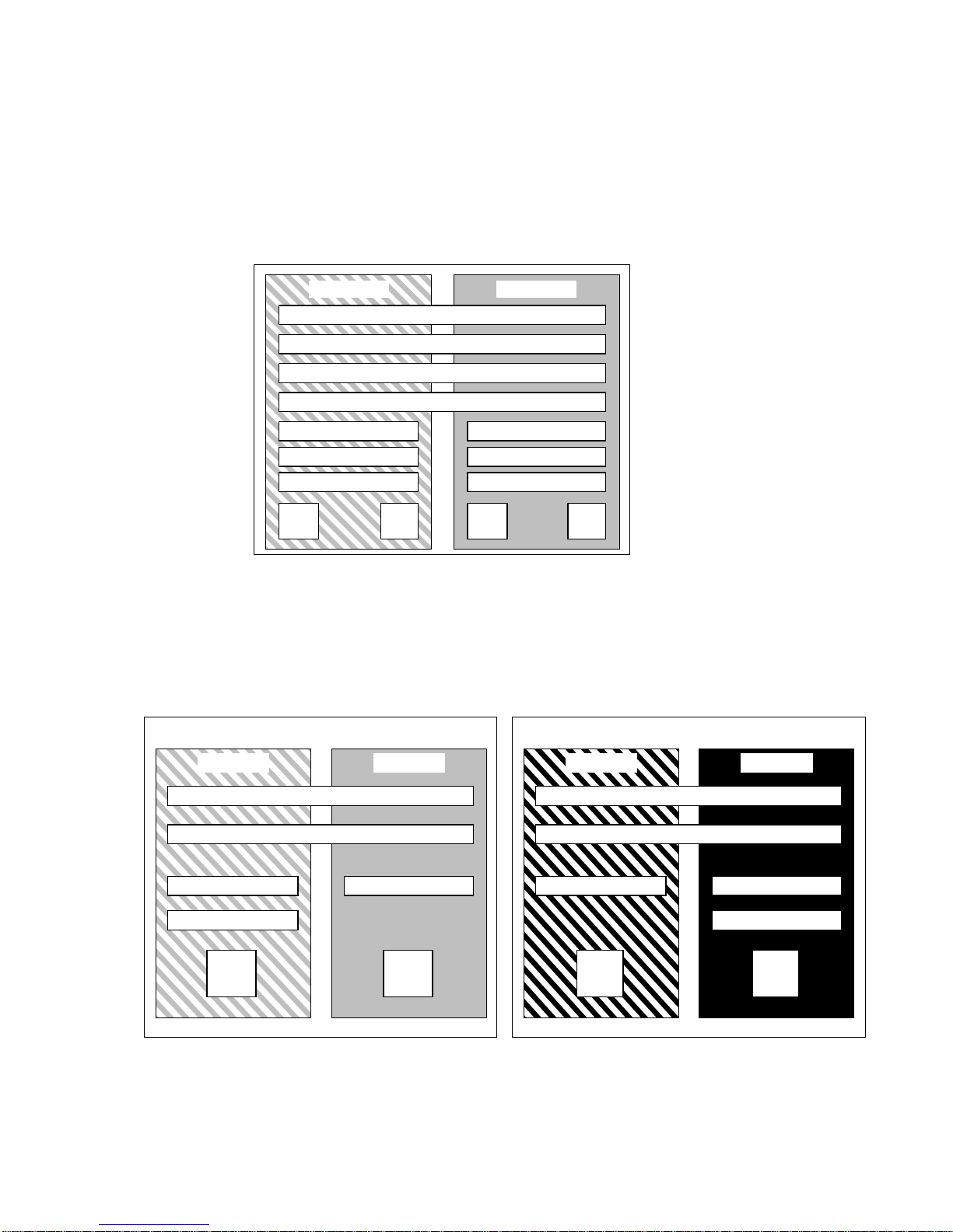
FIGURE 1-1 shows the Sun Fire 6800 system in single-partition mode. This system has
four Repeater boards that operate in pairs (RP0, RP2) and (RP1, RP3), six
CPU/Memory boards (SB0 - SB5), and four I/O assemblies (IB6 - IB9).
Partition 0
Domain A Domain B
RP0
RP1
RP2
RP3
SB0
SB2
SB4
SB1
SB3
SB5
IB6 IB8 IB7 IB9
FIGURE 1-1 Sun Fire 6800 System in Single-Partition Mode
FIGURE 1-2 shows the Sun Fire 6800 system in dual-partition mode. The same boards
and assemblies are shown as in
FIGURE 1-1.
Partition 0 Partition 1
Domain A Domain B Domain C Domain D
SB0
SB2
RP0
RP1
SB4 SB1 SB3
RP2
RP3
SB5
IB6 IB8 IB7 IB9
FIGURE 1-2 Sun Fire 6800 System in Dual-Partition Mode
Chapter 1 Introduction 5
Page 28
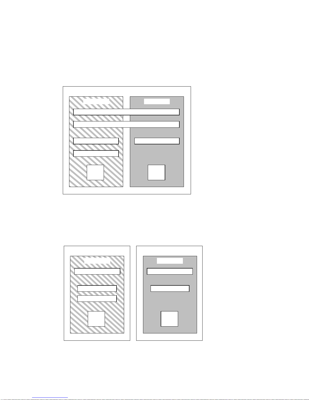
FIGURE 1-3 shows the Sun Fire 4810/4800 systems in single-partition mode. These
systems have two Repeater boards (RP0 and RP2) that operate separately (not in pairs
as in the Sun Fire 6800 system), three CPU/Memory boards (SB0, SB2, and SB4), and
two I/O assemblies (IB6 and IB8).
Partition 0
Domain A Domain B
RP0
RP2
SB0
SB2
SB4
IB6 IB8
FIGURE 1-3 Sun Fire 4810/4800 Systems in Single-Partition Mode
FIGURE 1-4 shows the Sun Fire 4810/4800 systems in dual-partition mode. The same
boards and assemblies are shown as in
FIGURE 1-3.
Partition 0 Partition 1
Domain A Domain C
RP0 RP2
SB0
SB4
IB6 IB8
FIGURE 1-4 Sun Fire 4810/4800 Systems in Dual-Partition Mode
6 Sun Fire 6800/4810/4800/3800 Systems Platform Administration Manual • May 2002
SB2
Page 29
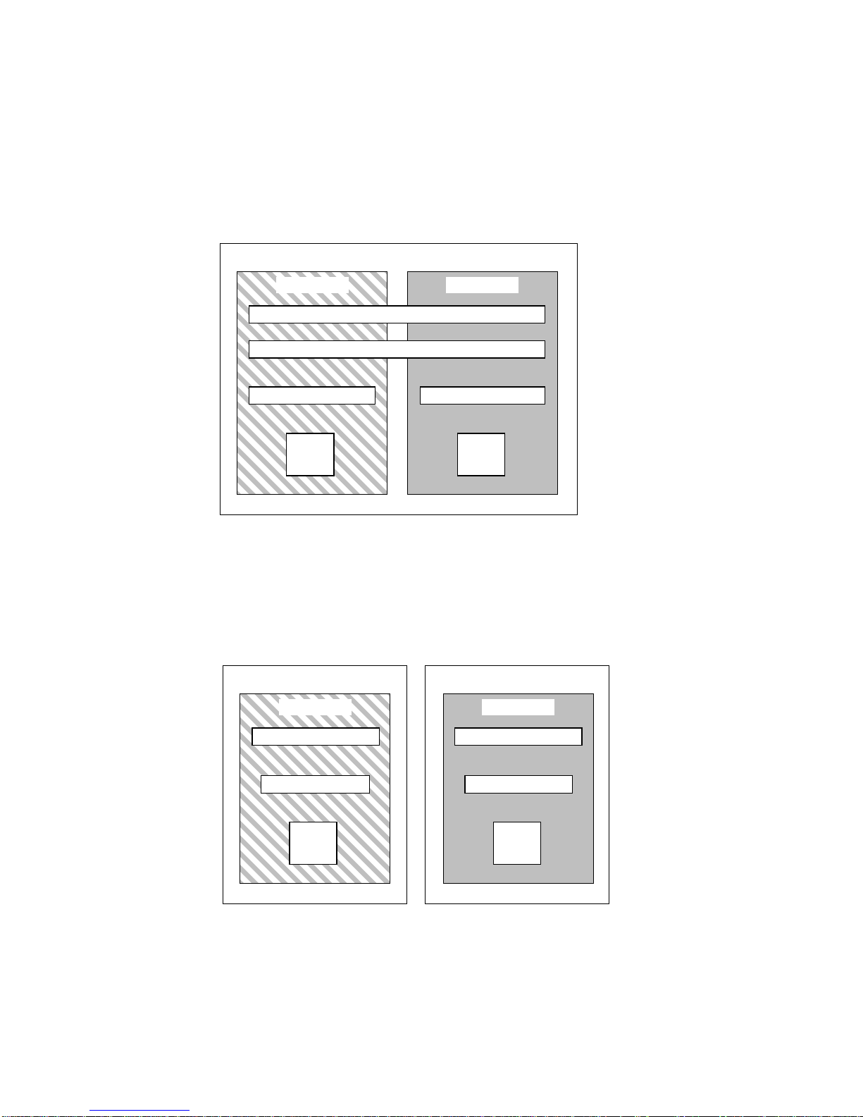
FIGURE 1-5 shows the Sun Fire 3800 system in single-partition mode. This system has
the equivalent of two Repeater boards (RP0 and RP2) integrated into the active
centerplane, two CPU/Memory boards (SB0 and SB2), and two I/O assemblies
(IB6 and IB8).
Partition 0
Domain A Domain B
RP0
RP2
SB0 SB2
IB6 IB8
FIGURE 1-5 Sun Fire 3800 System in Single-Partition Mode
FIGURE 1-6 shows the Sun Fire 3800 system in dual-partition mode. The same boards
and assemblies are shown as in
FIGURE 1-5. This system also has the equivalent of
two Repeater boards, RP0 and RP2, integrated into the active centerplane.
Partition 0 Partition 1
Domain A Domain C
RP0 RP2
SB0 SB2
IB6 IB8
FIGURE 1-6 Sun Fire 3800 System in Dual-Partition Mode
Chapter 1 Introduction 7
Page 30

System Controller
The system controller is an embedded system on a board that connects into the
centerplane of these mid-range systems. It is the focal point for platform and domain
configuration and management and is used to connect to the domain consoles.
System controller functions include:
■ Managing platform and domain resources
■ Monitoring the platform and domains
■ Configuring the domains and the platform
■ Providing access to the domain consoles
■ Providing the date and time to the Solaris operating environment
■ Providing the reference clock signal used throughout the system
■ Providing console security
■ Performing domain initialization
■ Providing a mechanism for upgrading firmware on the boards installed in the
system
■ Providing an external management interface using SNMP
The system can support up to two System Controller boards (
TABLE 1-4) that function
as a main and spare system controller. This redundant configuration of system
controllers supports the SC failover mechanism, which triggers the automatic
switchover of the main SC to the spare if the main SC fails. For details on SC
failover, see Chapter 7.
TABLE 1-4 Functions of System Controller Boards
System Controller Function
Main Manages all system resources. Configure your system to connect to
the main System Controller board.
Spare If the main system controller fails and a failover occurs, the spare
assumes all system controller tasks formerly handled by the main
system controller. The spare system controller functions as a hot
standby, and is used only as a backup for the main system
controller.
8 Sun Fire 6800/4810/4800/3800 Systems Platform Administration Manual • May 2002
Page 31

Serial and Ethernet Ports
There are two methods to connect to the system controller console:
■ Serial port —Use the serial port to connect directly to an ASCII terminal or to a
network terminal server (NTS).
■ Ethernet port—Use the Ethernet port to connect to the network.
For performance reasons, it is suggested that the system controllers be configured on
a private network. For details, refer to the article, Sun Fire Midframe Server Best
Practices for Administration,at
http://www.sun.com/blueprints
TABLE 1-5 describes the features of the serial port and the Ethernet port on the System
Controller board. The Ethernet port provides the fastest connection.
TABLE 1-5 Serial Port and Ethernet Port Features on the System Controller Board
Capability Serial Port Ethernet Port
Number of connections One Multiple
Connection speed 9.6 Kbps 10/100 Mbps
System logs Remain the system controller
message queue
SNMP Not supported Supported
Firmware upgrades No Yes (using the flashupdate command)
Security Secure physical location plus
secure terminal server
Remain in the system controller message
queue and are written to the configured
syslog host(s). See
up the loghosts for the platform shell and each
domain shell. Setting up loghosts makes sure
that error messages are captured when a
system failure occurs.
Password-protected access only
TABLE 3-1 for how to set
System Controller Logical Connection Limits
The system controller supports one logical connection on the serial port and
multiple logical connections with telnet on the Ethernet port. Connections can be
set up for either the platform or one of the domains. Each domain can have only one
logical connection at a time.
Chapter 1 Introduction 9
Page 32

System Controller Software
The sections that follow provide information on the system controller software,
including:
■ “Platform Administration” on page 10
■ “System Controller Tasks Completed at System Power-On” on page 11
■ “Domain Administration” on page 11
■ “Domain Keyswitch” on page 12
■ “Environmental Monitoring” on page 12
■ “Console Messages” on page 13
Platform Administration
The platform administration function manages resources and services that are
shared among the domains. With this function, you can determine how resources
and services are configured and shared.
Platform administration functions include:
■ Monitoring and controlling power to the components
■ Logically grouping hardware to create domains
■ Configuring the system controller’s network, loghost, and SNMP settings
■ Determining which domains may be used
■ Determining how many domains can be used (Sun Fire 6800 system only)
■ Configuring access control for CPU/Memory boards and I/O assemblies
Platform Shell
The platform shell is the operating environment for the platform administrator. Only
commands that pertain to platform administration are available. To connect to the
platform, see “To Obtain the Platform Shell Using telnet” on page 28 or “Obtaining
the Platform Shell” on page 28.
Platform Console
The platform console is the system controller serial port, where the system controller
boot messages and platform log messages are printed.
Note – The Solaris operating environment messages are displayed on the domain
console.
10 Sun Fire 6800/4810/4800/3800 Systems Platform Administration Manual • May 2002
Page 33

System Controller Tasks Completed at System Power-On
When you power on the system, the system controller boots the system controller
real time operating system and starts the system controller application.
If there was an interruption of power, additional tasks completed at system poweron include:
■ If a domain is active, the system controller turns on components needed to
support the active domain (power supplies, fan trays, and Repeater boards) as
well as the boards in the domain (CPU/Memory boards and I/O assemblies).
■ If no domains are active, only the system controller is powered on.
■ The system controller reboots any domains that were active when the system lost
power.
Domain Administration
The domain administration function manages resources and services for a specific
domain.
Domain administration functions include:
■ Configuring the domain settings
■ Controlling the virtual keyswitch
■ Recovering errors
For platform administration functions, see “Platform Administration” on page 10.
Domain Shell
The domain shell is the operating environment for the domain administrator and is
where domain tasks can be performed. There are four domain shells (A – D).
To connect to a domain, see “Obtaining a Domain Shell or Console” on page 30.
Chapter 1 Introduction 11
Page 34

Domain Console
If the domain is active (Solaris operating environment, the OpenBoot PROM, or
POST is running in the domain), you can access the domain console. When you
connect to the domain console, you will be at one of the following modes of
operation:
■ Solaris operating environment console
■ OpenBoot PROM
■ Domain will be running POST and you can view the POST output.
Maximum Number of Domains
The domains that are available vary with the system type and configuration. For
more information on the maximum number of domains you can have, see
“Partitions” on page 3.
Domain Keyswitch
Each domain has a virtual keyswitch. There are five keyswitch positions that you
can set: off (default), standby, on, diag, and secure. There are several other keyswitch
positions, which are transitional positions.
For information on keyswitch settings, see “Keyswitch Positions” on page 69. For a
description and syntax of the setkeyswitch command, refer to the Sun Fire
6800/4810/4800/3800 System Controller Command Reference Manual.
Environmental Monitoring
There are sensors throughout the system that monitor temperature, voltage, current,
and fan speed. The system controller periodically reads the values from each of these
sensors. This information is maintained for display using the console commands and
provided with SNMP.
When a sensor is generating values that are outside of the normal limits, the system
controller takes appropriate action. This includes shutting down components in the
system to prevent damage. Domains may be automatically shut down as a result. If
domains are shut down, be aware that an abrupt hardware shutdown occurs (it is
not a graceful shutdown of the Solaris operating environment).
12 Sun Fire 6800/4810/4800/3800 Systems Platform Administration Manual • May 2002
Page 35

Console Messages
The console messages generated by the system controller for the platform and for
each domain are printed on the appropriate console. The messages are stored in a
buffer on the system controller and can be logged to a syslog host. It is important to
note that these messages are not the Solaris operating environment console
messages.
To enhance accountability and for long-term storage, the messages should be sent to
syslog as syslog host.
The system controller does not have permanent storage for console messages. Both the
platform and each domain have a small buffer that maintains some history.
However, this information is lost when the system is rebooted or the system
controller loses power.
Redundant Components and Minimum
Configurations
The Sun Fire 6800/4810/4800/3800 systems are designed to increase availability by
having redundant components. The sections that follow discuss the redundant
hardware that can be installed:
■ Redundant System Controller Boards
■ “CPU/Memory Boards” on page 14
■ “I/O Assemblies” on page 15
■ “Redundant Cooling” on page 16
■ “Redundant Power” on page 17
■ “Repeater Boards” on page 18
■ “Redundant System Clocks” on page 19
For troubleshooting tips to perform if a board or component fails, see “Board and
Component Failures” on page 112.
Redundant System Controller Boards
Sun Fire 6800/4810/4800/3800 systems support two System Controller boards,
which serve as the main and spare system controllers. The main system controller
performs all system tasks and manages system resources, while the spare system
controller is available to assume the function of the main system controller if the
main fails.
Chapter 1 Introduction 13
Page 36

The SC failover software monitors the main and spare system controllers for
conditions that cause the main system controller to fail. If such failure conditions are
detected, the failover software causes a switchover of the main system controller to
the spare. For details on system controller failover, see Chapter 7.
CPU/Memory Boards
All systems support multiple CPU/Memory boards. Each domain must contain at
least one CPU/Memory board.
The maximum number of CPUs you can have on a CPU/Memory board is four.
CPU/Memory boards are configured with either two CPUs or four CPUs.
lists the maximum number of CPU/Memory boards for each system.
TABLE 1-6 Maximum Number of CPU/Memory Boards in Each System
System Maximum Number of
CPU/Memory Boards Maximum Number of CPUs
Sun Fire 6800 system 6 24
Sun Fire 4810 system 3 12
TABLE 1-6
Sun Fire 4800 system 3 12
Sun Fire 3800 system 2 8
Each CPU/Memory board has eight physical banks of memory. The CPU provides
memory management unit (MMU) support for two banks of memory. Each bank of
memory has four slots. The memory modules (DIMMs) must be populated in groups
of four to fill a bank. The minimum amount of memory needed to operate a domain
is one bank (four DIMMs).
A CPU can be installed and used without any memory in one of its banks. A
memory bank cannot be used unless the corresponding CPU is installed and
functioning. If a CPU is disabled, it is not functioning.
Redundant CPUs and Memory
A failed CPU or faulty memory will be isolated from the domain by the power-on
self-test (POST).
You can operate a domain with as little as one CPU and one memory bank (four
memory modules).
14 Sun Fire 6800/4810/4800/3800 Systems Platform Administration Manual • May 2002
Page 37

I/O Assemblies
All systems support multiple I/O assemblies. For the types of I/O assemblies
supported by each system and other technical information, refer to the Sun Fire
6800/4810/4800/3800 Systems Overview Manual.
of I/O assemblies for each system.
TABLE 1-7 Maximum Number of I/O Assemblies and I/O Slots per I/O Assembly
TABLE 1-7 lists the maximum number
System Maximum Number of I/O
Assemblies
Sun Fire 6800 system 4 • 8 slots—6 slots for full-length PCI cards
Sun Fire 4810 system 2 • 8 slots—6 slots for full-length PCI cards
Sun Fire 4800 system 2 • 8 slots—6 slots for full-length PCI cards
Sun Fire 3800 system 2 6 slots for CompactPCI cards
Number of CompactPCI or PCI I/O Slots
and 2 short slots for short PCI cards
• 4 slots for CompactPCI cards
and 2 short slots for short PCI cards
• 4 slots for CompactPCI cards
and 2 short slots for short PCI cards
• 4 slots for CompactPCI cards
Redundant I/O
There are two possible ways to configure redundant I/O (TABLE 1-8).
TABLE 1-8 Configuring for I/O Redundancy
Ways to Configure For I/O Redundancy Description
Redundancy across I/O assemblies You must have two I/O assemblies in a domain
Redundancy within I/O assemblies You must have duplicate cards in the I/O
with duplicate cards in each I/O assembly that
are connected to the same disk or network
subsystem for path redundancy.
assembly that are connected to the same disk or
network subsystem for path redundancy. This
does not protect against the failure of the I/O
assembly itself.
Chapter 1 Introduction 15
Page 38

The network redundancy features use part of the Solaris operating environment,
known as IP multipathing. For information on IP multipathing (IPMP), refer to the
Solaris documentation supplied with the Solaris 8 or 9 operating environment
release.
The Sun StorEdge
TM
Traffic Manager provides multipath disk configuration
management, failover support, I/O load balancing, and single instance multipath
support. For details, refer to the Sun StorEdge documentation available on the Sun
Network Solutions website:
http://www.sun.com/storage/san
Redundant Cooling
All systems have redundant cooling when the maximum number of fan trays are
installed. If one fan tray fails, the remaining fan trays automatically increase speed,
thereby enabling the system to continue to operate.
Caution – With the minimum number of fan trays installed, you do not have
redundant cooling.
With redundant cooling, you do not need to suspend system operation to replace a
failed fan tray. You can hot-swap a fan tray while the system is running, with no
interruption to the system.
TABLE 1-9 shows the minimum and maximum number of fan trays required to cool
each system For location information, such as the fan tray number, refer to the labels
on the system and to the Sun Fire 6800/4810/4800/3800 Systems Service Manual.
TABLE 1-9 Minimum and Maximum Number of Fan Trays
Minimum Number of
System
Sun Fire 6800 system 3 4
Sun Fire 4810 system 2 3
Sun Fire 4800 system 2 3
Sun Fire 3800 system 3 4
Fan Trays
Each system has comprehensive temperature monitoring to ensure that there is no
over-temperature stressing of components in the event of a cooling failure or high
ambient temperature. If there is a cooling failure, the speed of the remaining
operational fans increases. If necessary, the system is shut down.
16 Sun Fire 6800/4810/4800/3800 Systems Platform Administration Manual • May 2002
Maximum Number of
Fan Trays
Page 39

Redundant Power
In order for power supplies to be redundant, you must have the required number of
power supplies installed plus one additional redundant power supply for each
power grid (referred to as the n+1 redundancy model). This means that two power
supplies are required for the system to function properly. The third power supply is
redundant. All three power supplies draw about the same current.
The power is shared in the power grid. If one power supply in the power grid fails,
the remaining power supplies in the same power grid are capable of delivering the
maximum power required for the power grid.
If more than one power supply in a power grid fails, there will be insufficient power
to support a full load. For troubleshooting tips to perform when a power supply
fails, see “Power Supply Failure” on page 121.
The System Controller boards and the ID board obtain power from any power
supply in the system. Fan trays obtain power from either power grid.
TABLE 1-10 describes the minimum and redundant power supply requirements.
TABLE 1-10 Minimum and Redundant Power Supply Requirements
System Number of Power
Grids per System
Sun Fire 6800
system
Sun Fire 6800
system
Sun Fire 4810
system
Sun Fire 4800
system
Sun Fire 3800
system
2 2 (grid 0) 3
1 2 (grid 0) 3
1 2 (grid 0) 3
1 2 (grid 0) 3
Minimum Number of
Power Supplies In Each
Power Grid
2 (grid 1) 3
Total Number of Supplies In
Each Power Grid (Including
Redundant Power Supplies)
Each power grid has power supplies assigned to the power grid. Power supplies
ps0, ps1, and ps2 are assigned to power grid 0. Power supplies ps3, ps4, and ps5 are
assigned to power grid 1. If one power grid, such as power grid 0 fails, the
remaining power grid is still operational.
Chapter 1 Introduction 17
Page 40

TABLE 1-11 lists the components in the Sun Fire 6800 system in each power grid. If
you have a Sun Fire 4810/4800/3800 system, refer to the components in grid 0, since
these systems have only power grid 0.
TABLE 1-11 Sun Fire 6800 System Components in Each Power Grid
Components in the System Grid 0 Grid 1
CPU/Memory boards SB0, SB2, SB4 SB1, SB3, SB5
I/O assemblies IB6, IB8 IB7, IB9
Power supplies PS0, PS1, PS2 PS3, PS4, PS5
Repeater boards RP0, RP1 RP2, RP3
Redundant Transfer Unit (RTU) RTUR (rear) RTRF (front)
Repeater Boards
The Repeater board is a crossbar switch that connects multiple CPU/Memory boards
and I/O assemblies. Having the required number of Repeater boards is mandatory
for operation. There are Repeater boards in each mid-range system except for the
Sun Fire 3800. In the Sun Fire 3800 system, the equivalent of two Repeater boards are
integrated into the active centerplane. Repeater boards are not fully redundant.
For steps to perform if a Repeater board fails, see “Repeater Board Failure” on
page 117.
TABLE 1-12 lists the Repeater board assignments by each domain in the Sun
Fire 6800 system.
TABLE 1-12 Repeater Board Assignments by Domains in the Sun Fire 6800 System
Partition Mode Repeater Boards Domains
Single partition RP0, RP1, RP2, RP3 A, B
Dual partition RP0, RP1 A, B
Dual partition RP2, RP3 C, D
18 Sun Fire 6800/4810/4800/3800 Systems Platform Administration Manual • May 2002
Page 41

TABLE 1-13 lists the Repeater board assignments by each domain in the Sun Fire
4810/4800 systems.
TABLE 1-13 Repeater Board Assignments by Domains in the Sun Fire 4810/4800/3800
Systems
Partition Mode Repeater Boards Domains
Single partition RP0, RP2 A, B
Dual partition RP0 A
Dual partition RP2 C
TABLE 1-14 lists the configurations for single-partition mode and dual-partition mode
for the Sun Fire 6800 system regarding Repeater boards and domains.
TABLE 1-14 Sun Fire 6800 Domain and Repeater Board Configurations for Single- and Dual-Partitioned
Systems
Sun Fire 6800 System in Single-Partition Mode Sun Fire 6800 System in Dual-Partition Mode
RP0 RP1 RP2 RP3 RP0 RP1 RP2 RP3
Domain A Domain A Domain C
Domain B Domain B Domain D
TABLE 1-15 lists the configurations for single-partition mode and dual-partition mode
for the Sun Fire 4810/4800/3800 systems.
TABLE 1-15 Sun Fire 4810/4800/3800 Domain and Repeater Board Configurations for Single- and Dual-
Partitioned Systems
Sun Fire 4810/4800/3800 System in Single-Partition Mode Sun Fire 4810/4800/3800 System in Dual-Partition Mode
RP0 RP2 RP0 RP2
Domain A Domain A Domain C
Domain B
Redundant System Clocks
The System Controller board provides redundant system clocks. For more
information on system clocks, see “System Controller Clock Failover” on page 21.
Chapter 1 Introduction 19
Page 42

Reliability, Availability, and
Serviceability (RAS)
Reliability, availability, and serviceability (RAS) are features of these mid-range
systems. The descriptions of these features are:
■ Reliability is the probability that a system stays operational for a specified time
period when operating under normal conditions. Reliability differs from
availability in that reliability involves only system failure, whereas availability
depends on both failure and recovery.
■ Availability, also known as average availability, is the percentage of time that a
system is available to perform its functions correctly. Availability can be measured
at the system level or in the context of the availability of a service to an end client.
The “system availability” is likely to impose an upper limit on the availability of
any products built on top of that system.
■ Serviceability measures the ease and effectiveness of maintenance and system
repair for the product. There is no single well-defined metric, because
serviceability can include both mean time to repair (MTTR) and diagnosability.
The following sections provide details on RAS. For more hardware-related
information on RAS, refer to the Sun Fire 6800/4810/4800/3800 Systems Service
Manual. For RAS features that involve the Solaris operating environment, refer to the
Sun Hardware Platform Guide.
Reliability
The software reliability features include:
■ POST
■ Disabling of Components
■ Environmental Monitoring
■ System Controller Clock Failover
The reliability features also improve system availability.
POST
The power-on self-test (POST) is part of powering on a domain. A board or
component that fails POST will be disabled. The domain, running the Solaris
operating environment, is booted only with components that have passed POST
testing.
20 Sun Fire 6800/4810/4800/3800 Systems Platform Administration Manual • May 2002
Page 43

Disabling of Components
The system controller provides component-level status and user-controlled disabling
of components, which is also referred to as blacklisting. However, note that the
system controller does not actually maintain a blacklist file.
You can add a faulty component to a blacklist with the disablecomponent
command. Components in the blacklist will not be configured. You can remove a
component from the blacklist with the enablecomponent command.
The platform blacklists supersede the domain blacklists. For example, if a
component is disabled in the platform, it will always be disabled in all domains.
Blacklisting from the platform applies to all domains. Blacklisting in a domain
applies only to the current domain. If you disable a component in one domain and
then move the component to another domain, the component is not disabled. The
showcomponent command displays status information about the component,
including whether or not it has been disabled.
To enable a component that you previously disabled, you must enable it in the
domain(s) or from the platform.
For additional information on the types of components that can be blacklisted, see
“Disabling Components” on page 122.
Environmental Monitoring
The system controller monitors the system temperature, current, and voltage
sensors. The fans are also monitored to make sure they are functioning.
Environmental status is not provided to the Solaris operating environment—only the
need for an emergency shutdown. The environmental status is provided to the Sun
Management Center software with SNMP.
System Controller Clock Failover
Each system controller provides a system clock signal to each board in the system.
Each board automatically determines which clock source to use. Clock failover is the
ability to change the clock source from one system controller to another system
controller without affecting the active domains.
When a system controller is reset or rebooted, clock failover is temporarily disabled.
When the clock source is available again, clock failover is automatically enabled.
Chapter 1 Introduction 21
Page 44

Availability
The software availability features include:
■ System Controller Failover Recovery
■ Unattended Domain Reboot
■ Unattended Power Failure Recovery
■ System Controller Reboot Recovery
System Controller Failover Recovery
Systems with redundant System Controller boards support the SC failover
capability. In a high-availability system controller configuration, the SC failover
mechanism triggers the switchover of the main SC to the spare if the main SC fails.
Within approximately five minutes or less, the spare SC becomes the main and takes
over all system controller operations. For details on SC failover, see Chapter 7.
Unattended Domain Reboot
If the system controller detects a hardware error, the domain is rebooted. This
behavior is controlled by the reboot-on-error parameter of the setupdomain
command. This parameter, which is set to true by default, reboots the domain when
a hardware error is detected. If you set this parameter to false and the system
controller detects a hardware error, the domain is paused and it must be turned off,
then on again to recover. For details, see the setupdomain command in the Sun Fire
6800/4810/4800/3800 System Controller Command Reference Manual.
If the Solaris operating environment panics, the action taken depends on the type of
panic, the software configuration, and the hardware configuration. After the panic,
when POST runs, it disables any components that fail testing.
Unattended Power Failure Recovery
If there is a power outage, the system controller reconfigures active domains.
TABLE 1-16 describes domain actions that occur during or after a power failure when
the keyswitch is:
■ Active (set to on, secure, diag)
■ Inactive (set to off or standby)
■ Processing a keyswitch operation
22 Sun Fire 6800/4810/4800/3800 Systems Platform Administration Manual • May 2002
Page 45

TABLE 1-16 Results of setkeyswitch Settings During a Power Failure
If During a Power Failure the
Keyswitch Is This Action Occurs
on, secure, diag The domain will be powered on after a power
failure.
off, standby The domain will not be restored after a power
failure.
Processing a keyswitch operation,
such as off to on, standby to on, or
on to off
The domain will not be restored after a power
failure.
System Controller Reboot Recovery
The system controller can be rebooted and will start up and resume management of
the system. The reboot does not disturb the currently running domain(s) running the
Solaris operating environment.
Serviceability
The software serviceability features promote the efficiency and timeliness of
providing routine as well as emergency service to these systems.
LEDs
All field-replaceable units (FRUs) that are accessible from outside the system have
LEDs that indicate their state. The system controller manages all the LEDs in the
system, with the exception of the power supply LEDs, which are managed by the
power supplies. For a discussion of LED functions, refer to the appropriate board or
device chapter of the Sun Fire 6800/4810/4800/3800 Systems Service Manual.
Nomenclature
The system controller, the Solaris operating environment, the power-on self-test
(POST), and the OpenBoot PROM error messages use FRU name identifiers that
match the physical labels in the system. The only exception is the OpenBoot PROM
nomenclature used for I/O devices, which use the device path names as described in
Appendix A.
Chapter 1 Introduction 23
Page 46

System Controller Error Logging
You can configure the system controller platform and domains to log errors by using
the syslog protocol to an external loghost. The system controller also has an
internal buffer where error messages are stored. You can display the system
controller logged events, stored in the system controller message buffer, by using the
showlogs command. There is one log for the platform and one log for each of the
four domains.
System Controller XIR support
The system controller reset command enables you to recover from a hard hung
domain and extract a Solaris operating environment core file.
Dynamic Reconfiguration Software
Dynamic Reconfiguration (DR), which is provided as part of the Solaris operating
environment, enables you to safely add and remove CPU/Memory boards and I/O
assemblies while the system is still running. DR controls the software aspects of
dynamically changing the hardware used by a domain, with minimal disruption to
user processes running in the domain.
You can use DR to do the following:
■ Shorten the interruption of system applications while installing or removing a
board
■ Disable a failing device by removing it from the logical configuration, before the
failure can crash the operating system
■ Display the operational status of boards in a system
■ Initiate self tests of a system board while the domain continues to run
■ Reconfigure a system while the s ystem continues to run
■ Invoke hardware-specific functions of a board or a related attachment
The DR software uses the cfgadm command, which is a command line interface for
configuration administration. You can perform domain management DR tasks using
the system controller software. The DR agent also provides a remote interface to the
Sun Management Center software on Sun Fire 6800/4810/4800/3800 systems.
For complete information on DR, refer to the Sun Fire 6800, 4810, 4800, and 3800
Systems Dynamic Reconfiguration User Guide and also the Solaris documentation
included with the Solaris operating environment.
24 Sun Fire 6800/4810/4800/3800 Systems Platform Administration Manual • May 2002
Page 47

Sun Management Center Software for
the Sun Fire 6800/4810/4800/3800
Systems Software
For information on the Sun Management Center software for the Sun Fire
6800/4810/4800/3800 systems, refer to the Sun Management Center 3.0 Supplement for
Sun Fire 6800, 4810, 4800, and 3800 Systems, which is available online.
FrameManager
The FrameManager is an LCD display that is located in the top right corner of the
Sun Fire system cabinet. For a description of its functions, refer to the
“FrameManager” chapter of the Sun Fire 6800/4810/4800/3800 Systems Service Manual.
Chapter 1 Introduction 25
Page 48

26 Sun Fire 6800/4810/4800/3800 Systems Platform Administration Manual • May 2002
Page 49

CHAPTER
2
System Controller Navigation
Procedures
This chapter explains step-by-step procedures with illustrations describing how to:
■ Connect to the platform and the domains
■ Navigate between the domain shell and the domain console
■ Terminate a system controller session
Topics covered in this chapter include:
■ “Connection to the System Controller” on page 28
■ “Obtaining the Platform Shell” on page 28
■ “Obtaining a Domain Shell or Console” on page 30
■ “System Controller Navigation” on page 32
■ “To Enter the Domain Console From the Domain Shell If the Domain Is
Inactive” on page 35
■ “To Enter the Domain Shell From the Domain Console” on page 36
■ “To Get Back to the Domain Console From the Domain Shell” on page 36
■ “To Enter a Domain From the Platform Shell” on page 37
■ “Terminating Sessions” on page 37
■ “To Terminate an Ethernet Connection With telnet” on page 37
■ “To Terminate a Serial Connection With tip” on page 38
27
Page 50

Connection to the System Controller
This section describes how to obtain the following:
■ The platform shell
■ A domain shell or console
There are two types of connections: telnet and serial. If you are using a telnet
connection, configure the system controller network settings before using telnet.You
can access the system controller main menu using either the telnet or serial
connections.
From the main menu, you can select either the platform shell or one of the domain
consoles.
■ If you select the platform, you always obtain a shell.
■ If you select a domain, you obtain the:
■ Domain console (if the domain is active)
■ Domain shell (if the domain is inactive)
You can also bypass the system controller main menu by making a telnet connection
to a specific port.
Obtaining the Platform Shell
This section describes how to obtain the platform shell.
▼ To Obtain the Platform Shell Using telnet
Before you use telnet, be sure to configure the network settings for the system
controllers.
1. Obtain the system controller main menu by typing telnet schostname
(
CODE EXAMPLE 2-1).
where:
schostname is the system controller host name.
The system controller main menu is displayed.
enter the platform shell.
CODE EXAMPLE 2-1 shows how to
28 Sun Fire 6800/4810/4800/3800 Systems Platform Administration Manual • May 2002
Page 51

CODE EXAMPLE 2-1 Obtaining the Platform Shell With telnet
% telnet schostname
Trying xxx.xxx.xxx.xxx
Connected to schostname.
Escape character is ’^]’.
System Controller ‘schostname’:
Type 0 for Platform Shell
Type 1 for domain A
Type 2 for domain B
Type 3 for domain C
Type 4 for domain D
Input: 0
Connected to Platform Shell
schostname:SC>
Note – schostname is the system controller host name.
2. Type 0 to enter the platform shell.
The system controller prompt, schostname:SC>, is displayed for the platform shell of
the main system controller. If you have a redundant SC configuration, the spare
system controller prompt is schostname:sc>.
▼ To Initiate a Serial Connection with tip
● At the machine prompt, type tip and the serial port to be used for the system
controller session.
machinename% tip port_name
connected
The main system controller menu is displayed.
Chapter 2 System Controller Navigation Procedures 29
Page 52

▼ To Obtain the Platform Shell Using the Serial Port
1. Connect the system controller serial port to an ASCII terminal.
The system controller main menu is displayed.
2. From the main menu type 0 to enter the platform shell.
Obtaining a Domain Shell or Console
This section describes the following:
■ “To Obtain the Domain Shell Using telnet” on page 30
■ “To Obtain the Domain Shell From the Domain Console” on page 32
▼ To Obtain the Domain Shell Using telnet
1. Obtain the system controller main menu by typing telnet schostname
(
CODE EXAMPLE 2-2).
The system controller main menu is displayed.
where:
schostname is the system controller host name.
CODE EXAMPLE 2-2 shows entering the shell for domain A.
30 Sun Fire 6800/4810/4800/3800 Systems Platform Administration Manual • May 2002
Page 53

CODE EXAMPLE 2-2 Obtaining a Domain Shell With telnet
% telnet schostname
Trying xxx.xxx.xxx.xxx
Connected to schostname.
Escape character is ’^]’.
System Controller ‘schostname’:
Type 0 for Platform Shell
Type 1 for domain A
Type 2 for domain B
Type 3 for domain C
Type 4 for domain D
Input: 1
Connected to Domain A
Domain Shell for Domain A
schostname:A>
2. Enter a domain. Type 1, 2, 3,or4 to enter the appropriate domain shell.
The system controller prompt for the domain shell you connected to is displayed.
CODE EXAMPLE 2-2 shows entering the shell for domain A, whose prompt is
schostname:A>.
3. If the domain is active (the domain keyswitch is set to on, diag, or secure which
means you are running the Solaris operating environment, are in the OpenBoot
PROM, or are running POST), perform the following steps:
a. Press and hold the CTRL key while pressing the ] key, to get to the telnet>
prompt.
b. At the telnet> prompt type send break (
CODE EXAMPLE 2-3).
Chapter 2 System Controller Navigation Procedures 31
Page 54
CODE EXAMPLE 2-3 Obtaining a Domain Shell From the Domain Console
ok Ctrl-]
telnet> send break
▼ To Obtain the Domain Shell From the Domain Console
If the domain is active and the domain keyswitch is set to on, diag, or secure (you
are running the Solaris operating environment, are in the OpenBoot PROM, or are
running POST), perform the following steps:
1. Press and hold the CTRL key while pressing the ] key, to get to the telnet>
prompt.
2. At the telnet> prompt type send break.
CODE EXAMPLE 2-4 shows obtaining the shell for domain A from the domain console.
Because the domain is active, you will not see a prompt.
CODE EXAMPLE 2-4 Obtaining a Domain Shell From the Domain Console
ok Ctrl-]
telnet> send break
System Controller Navigation
This section explains how to navigate between the:
■ System controller platform
■ System controller domain console
■ System controller domain shell
To return to the originating shell, use the disconnect command. In a domain shell,
to connect to the domain console, use the resume command. To connect to a domain
shell from the platform shell, use the console command.
32 Sun Fire 6800/4810/4800/3800 Systems Platform Administration Manual • May 2002
Page 55
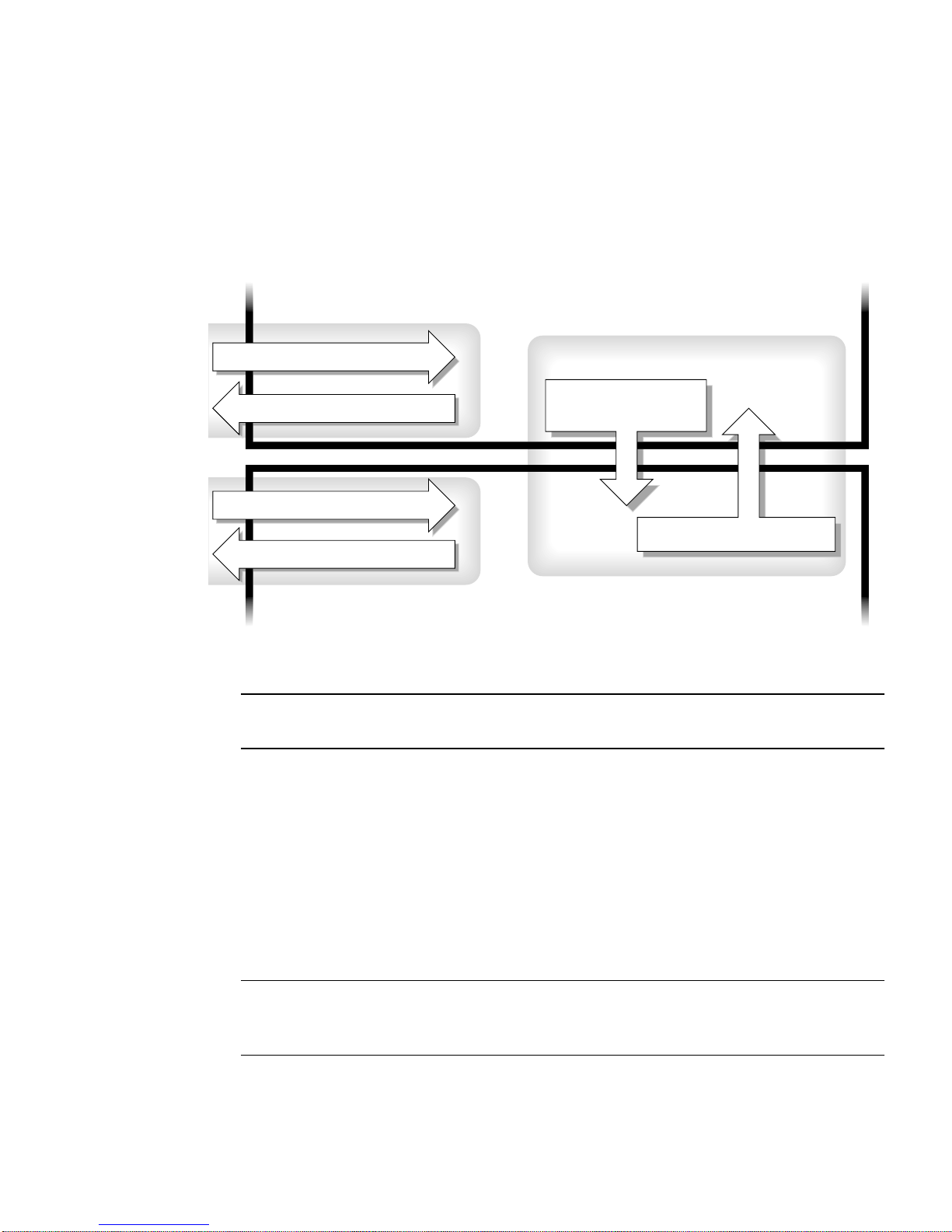
FIGURE 2-1 shows how to navigate between the platform shell, the domain shell, the
domain console by using the console and disconnect commands.
FIGURE 2-1 also
shows how to connect to both the domain shell and platform shell from the
operating environment by using the telnet command.
Domain shell
Domain
Type: telnet schostname 500x
disconnect
Type:
disconnect
Type:
Type: telnet schostname 5000
Type: console
Type:
FIGURE 2-1 Navigating Between the Platform Shell and the Domain Shell
disconnect
Platform shell
Platform shell
domainID
Note – You can also use the telnet command without the port number, as
described in CODE EXAMPLE 2-1 and CODE EXAMPLE 2-2.
where:
In the telnet command in
x is:
■ 1 for domain A
■ 2 for domain B
■ 3 for domain C
■ 4 for domain D
In the console command, domainID is a, b, c,ord.
Note – By typing telnet schostname 500x, you will bypass the system controller
main menu and directly enter the platform shell, a domain shell or a domain
console.
FIGURE 2-1, 5000 is the platform shell.
Chapter 2 System Controller Navigation Procedures 33
Page 56
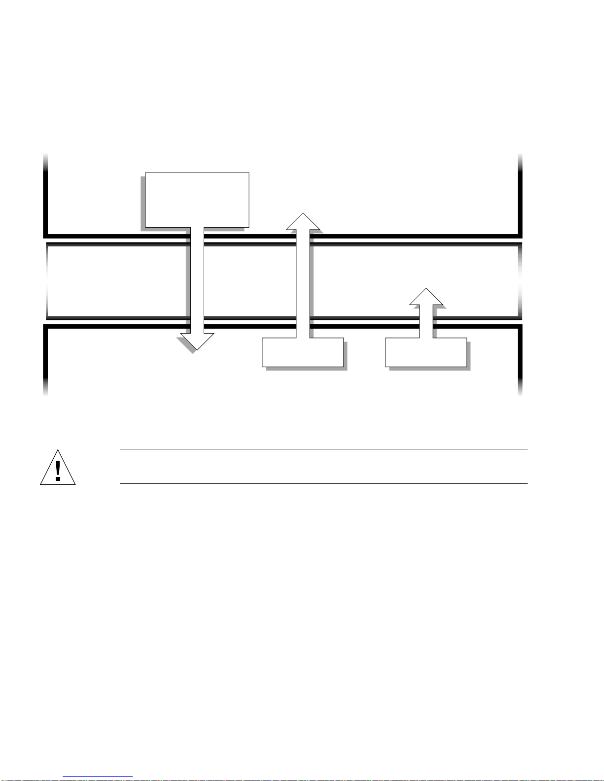
FIGURE 2-2 illustrates how to navigate between the Solaris operating environment,
the OpenBoot PROM, and the domain shell.
FIGURE 2-2 assumes that the Solaris
operating environment is running.
Solaris
operating
environment
login:
OpenBoot
PROM
ok
Domain shell
schostname:domainID
FIGURE 2-2 Navigating Between the Domain Shell, the OpenBoot PROM, and the Solaris
Caution – Note that in FIGURE 2-2 typing the break command suspends the Solaris
operating environment.
Press: CTRL ]
At the telnet>
prompt type:
send break
Type: resume Type: break
Operating Environment
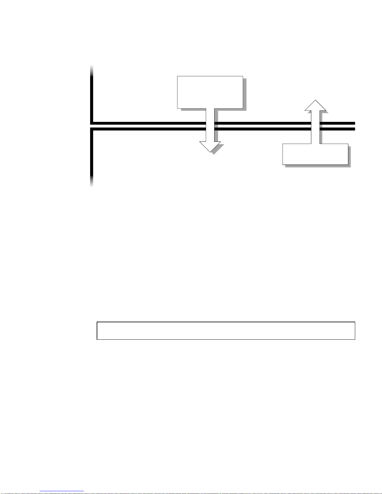
FIGURE 2-3 illustrates how to navigate between the OpenBoot PROM and the domain
shell. This figure assumes that the Solaris operating environment is not running.
34 Sun Fire 6800/4810/4800/3800 Systems Platform Administration Manual • May 2002
Page 57
Press: CTRL ]
OpenBoot
PROM
ok
Domain shell
schostname:domainID
FIGURE 2-3 Navigating Between the OpenBoot PROM and the Domain Shell
At the telnet>
prompt type:
send break
Type: resume
When you connect to a domain, you will be connected to the domain shell unless the
domain is active in which case you will be connected to the domain console. When
you connect to the console, you will be connected to the Solaris operating
environment console, the OpenBoot PROM, or POST, depending of which of these is
currently executing.
▼ To Enter the Domain Console From the Domain
Shell If the Domain Is Inactive
● Type setkeyswitch on in the domain shell.
schostname:A> setkeyswitch on
The domain console is only available when the domain is active. To make the
domain active, you must turn the keyswitch on. You will be automatically switched
from the domain shell to the domain console.
This action powers on and initializes the domain. The domain will go through POST
and then the OpenBoot PROM. If the OpenBoot PROM auto-boot? parameter is
set to true, the Solaris operating environment will boot.
Chapter 2 System Controller Navigation Procedures 35
Page 58

▼ To Enter the Domain Shell From the Domain
Console
1. Press and hold the CTRL key while pressing the ] key to get to the telnet>
prompt (
2. Type send break at the telnet prompt.
CODE EXAMPLE 2-5 Obtaining a Domain Shell From the Domain Console
ok Ctrl-]
telnet> send break
CODE EXAMPLE 2-5).
▼ To Get Back to the Domain Console From the
Domain Shell
1. Type resume:
schostname:D> resume
Note that because the domain is active, you will get a blank line.
2. Press the Return key to get a prompt.
Note – If the domain is not active, (the Solaris operating environment or the
OpenBoot PROM is not running), the system controller stays in the domain shell and
you will obtain an error.
36 Sun Fire 6800/4810/4800/3800 Systems Platform Administration Manual • May 2002
Page 59

▼ To Enter a Domain From the Platform Shell
Note – This example shows entering an inactive domain.
● Type:
schostname:SC> console -d a
Connected to Domain A
Domain Shell for Domain A
schostname:A>
If the OpenBoot PROM is running, you are returned to the console for domain A. If
the keyswitch is set to off or standby, you are returned to the shell for domain A.
Note – To enter another domain, type the proper domainID b, c,ord.
Terminating Sessions
This section describes how to terminate system controller sessions.
▼ To Terminate an Ethernet Connection With
telnet
● Type the disconnect command at the domain shell prompt.
Your system controller session terminates.
schostname:A> disconnect
Connection closed by foreign host.
machinename%
This example assumes that you are connected directly to the domain and not from
the platform shell.
Chapter 2 System Controller Navigation Procedures 37
Page 60
Note – If you have a connection to the domain initiated on the platform shell, you
must type disconnect twice.
Typing disconnect the first time takes you back to the platform shell connection
and keeps your connection to the system controller. Typing disconnect again exits
the platform shell and ends your connection to the system controller.
▼ To Terminate a Serial Connection With tip
If you are connected to the System Controller board with the serial port, use the
disconnect command to terminate the system controller session then use a tip
command to terminate your tip session.
1. At the domain shell or platform shell prompt, type disconnect.
schostname:A> disconnect
2. If you are in a domain shell and are connected from the platform shell, type
disconnect again to disconnect from the system controller session.
schostname:SC> disconnect
The system controller main menu is displayed.
38 Sun Fire 6800/4810/4800/3800 Systems Platform Administration Manual • May 2002
Page 61

3. Type ~. to end your tip session (CODE EXAMPLE 2-6).
CODE EXAMPLE 2-6 Ending a tip Session
System Controller ‘schostname’:
Type 0 for Platform Shell
Type 1 for domain A
Type 2 for domain B
Type 3 for domain C
Type 4 for domain D
Input: ~.
machinename%
The machinename% prompt is displayed.
Chapter 2 System Controller Navigation Procedures 39
Page 62

40 Sun Fire 6800/4810/4800/3800 Systems Platform Administration Manual • May 2002
Page 63

CHAPTER
3
System Power On and Setup
This chapter provides information to enable you to power on your system for the
first time and perform software setup procedures using the system controller
command line interface. For instructions on how to subsequently power on your
system, see “To Power On the System” on page 68.
Note – When you are setting up your system for the first time, it is strongly
suggested that you bring up the one domain set up for you, domain A, by installing
the Solaris operating environment in the domain and then booting it before creating
additional domains.
Before you create additional domains, make sure that domain A is operational, can
be accessed from the main menu, and you can boot the Solaris operating
environment in the domain. It is good policy to validate that one domain, domain A,
is functioning properly before you create additional domains. To create additional
domains, see Chapter 4.
This chapter contains the following topics:
■ “Installing, Cabling, and Powering on the Hardware” on page 43
■ “Powering On the Power Grids” on page 45
■ “Setting Up the Platform” on page 46
■ “Setting Up Domain A” on page 48
■ “Saving the Current Configuration to a Server” on page 50
■ “Installing and Booting the Solaris Operating Environment” on page 51
FIGURE 3-1 is a flowchart summarizing the major steps you must perform to power
on and set up the system, which are explained in step-by-step procedures in this
chapter.
41
Page 64
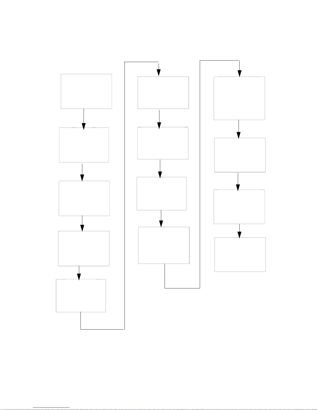
Install and cable
hardware.
Set up platform
specific parameters
with the
setupplatform
command.
Have the platform
administrator save
the system
configuration with
the dumpconfig
command
Set up services
before powering
on the hardware.
Power on the
hardware and
the power grid(s).
Set the date
and time for
the platform.
Set the date and
time for domain A.
Set the password
for domain A.
Set up domainspecific parameters
with the
setupdomain
command.
Turn on the
domain keyswitch.
If the Solaris
operating
environment.
is not preinstalled, install it.
Boot the Solaris
operating
environment.
Set the password
for the platform.
FIGURE 3-1 Flowchart of Power On and System Setup Steps
42 Sun Fire 6800/4810/4800/3800 Systems Platform Administration Manual • May 2002
Page 65

Installing, Cabling, and Powering on the
Hardware
1. Install and cable the hardware.
See the installation guide for your system.
2. Connect a terminal to your system using the serial port.
Refer to the installation guide for your system.
3. When you set up the terminal, set the ASCII terminal to the same baud rate as the
serial port.
The default serial port settings for the System Controller board are:
■ 9600 baud
■ 8 data bits
■ No parity
■ 1 stop bit
Because this is the platform console connection, log messages are displayed.
Setting Up Additional Services Before System
Power On
● Before you power on the system for the first time, set up the services described in
TABLE 3-1.
TABLE 3-1 Services That Should Be Set Up Before System Power On
Service Description
DNS services The system controller uses DNS to simplify communication with other systems.
Sun Managment
Center 3.0 software*
Network Terminal
Server (NTS)
* It is not necessary to have the loghost set up before you install and boot the Solaris operating environment. You can install
the Sun Managment Center 3.0 software after you boot your system for the first time. Because you can install from a
CD-ROM, it is not necessary to have a boot/install server set up before system power on.
Manage and monitor your system by using the Sun Management Center software for
the Sun Fire 6800/4810/4800/3800 systems. It is suggested that you use this software
to manage and monitor your system.
A Network Terminal Server (NTS) is used to help manage multiple serial connections.
The NTS should be secured with at least a password.
Chapter 3 System Power On and Setup 43
Page 66

TABLE 3-1 Services That Should Be Set Up Before System Power On (Continued)
Service Description
Boot/install server* Allows you to install the Solaris operating environment from a network server instead
of using a CD-ROM.
http/ftp server* In order to perform firmware upgrades, you must set up either an http or an ftp server.
In order to read/write the configuration backup files for the system controller
dumpconfig and restoreconfig commands, you need to set up an ftp server.
Loghost* The loghost system is used to collect system controller messages. In order to
permanently save loghost error messages, you must set up a loghost server.
• Use the setupplatform -p loghost command to output platform messages to the
loghost.
• Use the setupdomain -d loghost command to output domain messages to the
loghost.
There is a loghost for the platform and for each domain. For complete information and
command syntax, refer to the Sun Fire 6800/4810/4800/3800 System Controller Command
Reference Manual.
For information on the Solaris operating environment loghost, including how to
redirect error messages, refer to the Sun Hardware Platform Guide, which is available
with your Solaris operating environment release.
System controller If you plan to put the system controller(s) on a network, each system controller
installed must have an IP address. Each system controller should also have a serial
connection.
Domains Each domain you plan to use needs to have its own IP address.
* It is not necessary to have the loghost set up before you install and boot the Solaris operating environment. You can install
the Sun Managment Center 3.0 software after you boot your system for the first time. Because you can install from a
CD-ROM, it is not necessary to have a boot/install server set up before system power on.
44 Sun Fire 6800/4810/4800/3800 Systems Platform Administration Manual • May 2002
Page 67
Powering On the Hardware
● Complete the hardware power-on steps detailed and illustrated in the installation
guide for your system.
Powering On the Power Grids
1. Access the system controller and connect to the system controller main menu.
See “Connection to the System Controller” on page 28.
2. Connect to the platform shell.
3. Power on the power grid(s).
The poweron gridx command powers on power supplies in that power grid.
■ If you have a Sun Fire 6800 system, you must power on power grid 0 and power
grid 1.
schostname:SC> poweron grid0 grid1
■ If you have a Sun Fire 4810/4800/3800 system, there is only one power grid,
grid 0.
schostname:SC> poweron grid0
The poweron grid0 system controller command powers on power supplies in
power grid 0.
Chapter 3 System Power On and Setup 45
Page 68

Setting Up the Platform
After powering on the power grids, set up your system using the commands
described in this chapter.
This section contains the following topics:
■ To Set the Date and Time for the Platform
■ To Set a Password for the Platform
■ To Configure Platform Parameters
▼ To Set the Date and Time for the Platform
The platform and each of the four domains have separate and independent dates
and times.
Note – If your time zone area is using daylight or summer time, the time and time
zone are adjusted automatically. On the command line, you can enter only nondaylight time zones.
● Set the date, time, and time zone for the platform, by doing one of the following:
■ Use the setdate command from the platform shell.
For complete command syntax, examples, a table of time zone abbreviations, time
zone names, and offsets from Greenwich mean time, refer to the setdate
command in the Sun Fire 6800/4810/4800/3800 System Controller Command Reference
Manual.
If you have a redundant SC configuration, you must run the setdate command
on each system controller and set the same date and time for each SC. The
platform date and time must be the same on both the main and spare SC for
failover purposes.
■ Assign a Simple Time Network Protocol (SNTP) server through the
setupplatform command.
You can assign an SNTP server that synchronizes the date and time between the
main and spare system controller. The platform date and time must be the same
on both the main and spare SC for failover purposes. To assign an SNTP server,
use the setupplatform command, which is described in the Sun Fire
6800/4810/4800/3800 System Controller Command Reference Manual.
46 Sun Fire 6800/4810/4800/3800 Systems Platform Administration Manual • May 2002
Page 69

Note – Although you can set a different date and time for the platform and for each
domain, it is strongly suggested that you use the same date and time for the
platform and each domain.
Using the same date and time for the platform shell and each domain shell may help
during interpretation of error messages and logs. The date and time set on the
domains is also used by the Solaris operating environment.
▼ To Set a Password for the Platform
The system controller password that you set for the main system controller also
serves as the same password for the spare system controller.
1. From the platform shell, type the system controller password command.
2. At the Enter new password: prompt, type in your password.
3. At the Enter new password again: prompt, type in your password again.
For examples, refer to the password command in the Sun Fire 6800/4810/4800/3800
System Controller Command Reference Manual.
▼ To Configure Platform Parameters
Note – One of the platform configuration parameters that can be set through the
setupplatform command is the partition parameter. Determine if you want to set
up your system with one partition or two partitions. Read “Domains” on page 2 and
“Partitions” on page 3 before completing the following steps.
1. From the platform shell, type setupplatform.
For a description of the setupplatform parameter values and an example of this
command, refer to the setupplatform command in the Sun Fire
6800/4810/4800/3800 System Controller Command Reference Manual.
schostname:SC> setupplatform
Note – If you press the Return key after each parameter, the current value will not
be changed. If you type a dash ( - ), this clears the entry (if the entry can be blank).
Chapter 3 System Power On and Setup 47
Page 70

2. If you have a second System Controller board installed, run the setupplatform
command on the second system controller.
All of the parameters, except for the network settings (such as the IP address and
hostname of the system controller) and the POST diag level, are copied from the
main system controller to the spare.
Setting Up Domain A
In order to set up a domain, you must complete the procedures:
■ “To Access the Domain” on page 48
■ “To Set the Date and Time for Domain A” on page 48
■ “To Set a Password for Domain A” on page 48
■ “To Configure Domain-Specific Parameters” on page 49
▼ To Access the Domain
● Access the domain.
For more information, see “System Controller Navigation” on page 32.
▼ To Set the Date and Time for Domain A
● Type the setdate command in the domain A to set the date and time for the
domain.
Note – Because you can have up to four domains, you must eventually set the date
and time for each domain. To start, just set the date and time for domain A.
For command syntax and examples, refer to the setdate command in the Sun Fire
6800/4810/4800/3800 System Controller Command Reference Manual andto“ToSetthe
Date and Time for the Platform” on page 46.
▼ To Set a Password for Domain A
1. From the domain A shell, type the password command (CODE EXAMPLE 3-1).
2. At the Enter new password: prompt, type your password.
48 Sun Fire 6800/4810/4800/3800 Systems Platform Administration Manual • May 2002
Page 71

3. At the Enter new password again: prompt, type your password again
(
CODE EXAMPLE 3-1).
CODE EXAMPLE 3-1 password Command Example For a Domain With No Password Set
schostname:A> password
Enter new password:
Enter new password again:
schostname:A>
▼ To Configure Domain-Specific Parameters
Note – Each domain is configured separately.
1. From the domain A shell, type the setupdomain command.
For a listing of parameter values and sample output, refer to the setupdomain
command in the Sun Fire 6800/4810/4800/3800 System Controller Command Reference
Manual.
2. Perform the steps listed in
TABLE 3-2 Steps in Setting up Domains Including the dumpconfig Command
If you are setting up one domain . . . If you are setting up more than one domain . . .
1. Continue with the procedures in this chapter. 1. Install and boot the Solaris operating environment
TABLE 3-2.
on domain A as described in “To Install and Boot
the Solaris Operating Environment” on page 51.
2. Go to Chapter 4 to set up additional domains.
3. After all of the domains are set up and before you
start each additional domain you set up, have the
platform administrator run the dumpconfig
command. See “To Use dumpconfig to Save
Platform and Domain Configurations” on page 50.
Chapter 3 System Power On and Setup 49
Page 72

Saving the Current Configuration to a
Server
This section describes how to use the dumpconfig command, which must be run by
the platform administrator, to save the current system controller (SC) configuration
to a server. Use dumpconfig to save the SC configuration for recovery purposes.
Use the dumpconfig command when you
■ First set up your system and need to save the platform and domain
configurations.
■ Change the platform and domain configurations with one of the following system
controller commands (setupdomain, setupplatform, setdate, addboard,
deleteboard, enablecomponent, disablecomponent, and password)or
install and remove a CPU/Memory board or I/O assembly.
▼ To Use dumpconfig to Save Platform and
Domain Configurations
Use dumpconfig to save the platform and domain configurations to a server so that
you can restore the platform and domain configurations to a replacement system
controller (if the current system controller fails).
Note – Do not save the configuration to a domain on this system running the Solaris
operating environment. This is because the domain will be unavailable when the
system is restored.
● Type the system controller dumpconfig command from the platform shell to save
the present system controller configuration to a server.
schostname:SC> dumpconfig -f url
For command syntax, a description, command output, and examples, refer to the
dumpconfig command in the Sun Fire 6800/4810/4800/3800 System Controller
Command Reference Manual.
50 Sun Fire 6800/4810/4800/3800 Systems Platform Administration Manual • May 2002
Page 73
Installing and Booting the Solaris
Operating Environment
▼ To Install and Boot the Solaris Operating
Environment
1. Access the domain A shell.
See “Obtaining a Domain Shell or Console” on page 30.
2. Turn the domain A keyswitch to the on position. Type setkeyswitch on.
The setkeyswitch on command powers on the domain. If the OpenBoot PROM
auto-boot? parameter is set to true, you might obtain an error message similar to
CODE EXAMPLE 3-2.
CODE EXAMPLE 3-2 Sample Boot Error Message When the auto-boot? Parameter Is Set
To true
{0} ok boot
ERROR: Illegal Instruction
debugger entered.
{0} ok
The OpenBoot PROM displays this error message because the Solaris operating
environment might not yet be installed, or perhaps you are booting off the wrong
disk.
3. Insert the CD for the Solaris operating environment into the CD-ROM drive.
4. Install the Solaris operating environment on your system.
Refer to the Sun Hardware Platform Guide for your operating system release. That
book will refer to the installation guide you will need.
5. Boot the Solaris operating system by typing the OpenBoot PROM boot cdrom
command at the ok prompt.
ok boot cdrom
Chapter 3 System Power On and Setup 51
Page 74

52 Sun Fire 6800/4810/4800/3800 Systems Platform Administration Manual • May 2002
Page 75

CHAPTER
4
Creating and Starting Multiple
Domains
This chapter assumes that domain A, which was set up for you by Sun, is bootable.
This chapter explains how to create additional domains and how to start domains.
Note – The system is shipped from the factory configured with one domain, domain
A. All system boards are assigned to domain A.
Creating and Starting Domains
This section explains how to set up two or more domains.
Before Creating Multiple Domains
1. Determine how many domains you can have in your system and how many
partitions you need.
Read “Domains” on page 2 and “Partitions” on page 3. If you have a Sun Fire 6800
system and you are planning to set up three or four domains, you will need to set up
dual partition mode (two partitions). It may be helpful to maintain at least one
unused domain for testing hardware before dynamically reconfiguring it into the
system.
53
Page 76

Note – For all systems, it is strongly suggested that you use dual partition mode to
support two domains. Using two partitions to support two domains provides better
isolation between domains.
2. Determine the number of boards and assemblies that will be in each domain.
A domain must contain a minimum of one CPU/Memory board and one I/O
assembly. However, it is suggested that you have at least two CPU/Memory boards
and I/O assemblies for high availability configurations. If you have a Sun Fire 6800
system, go to the next step.
3. If you have a Sun Fire 6800 system, complete this step. The Sun Fire 6800 system
has two power grids, grid 0 and grid 1. It is strongly suggested that you set up
boards in a domain to be in the same power grid in order to isolate the domain
from a power failure.
Read “Redundant Power” on page 17 to learn how boards are divided between grid
0 and grid 1.
4. If you need to configure two partitions, turn off all domains.
a. If the Solaris operating environment is running in the domain, complete Step a
through Step d of Step 3 in “To Power Off the System” on page 66, then return
to Step 2 of this procedure.
Otherwise, skip to Step 5.
b. Configure the partition mode to dual.
Refer to the setupplatform command in the Sun Fire 6800/4810/4800/3800
System Controller Command Reference Manual.
5. If you do not need to configure two partitions and if the board that you plan to
assign to a new domain is currently used by domain A, shut down domain A or
use DR to unconfigure and disconnect the board out of the domain.
To shut down the domain, complete Step a through Step d of Step 3 in “To Power Off
the System” on page 66.
You can use the cfgadm command to remove the board from the domain, without
shutting down the domain. Refer to the Sun Fire 6800, 4810, 4800, and 3800 Systems
Dynamic Reconfiguration User Guide.
54 Sun Fire 6800/4810/4800/3800 Systems Platform Administration Manual • May 2002
Page 77
▼ To Create A Second Domain
Note – It is strongly suggested that you use domain C with two partitions (dual
partition mode) for your second domain. It provides better fault isolation (complete
isolation of Repeater boards). With one partition, use domain B for the second
domain.
Note – The steps to create a second domain should be performed by the platform
administrator.
1. Complete all steps in “Before Creating Multiple Domains” on page 53.
2. If you have boards that are assigned, type the deleteboard command from the
platform shell to unassign the boards you want to move from one domain to
another domain:
schostname:SC> deleteboard sbx ibx
where:
sbx is sb0 through sb5 (CPU/Memory boards)
ibx is ib6 through ib9 (I/O assemblies)
3. Assign the boards to the new domain with the addboard command.
■ If you have one partition, to add sbx and ibx to domain B, from the platform
shell, type:
schostname:SC> addboard -d b sbx ibx
■ If you have two partitions, to add sbx and ibx to domain C, from the platform
shell, type:
schostname:SC> addboard -d c sbx ibx
4. From the platform shell access the proper domain shell.
See “System Controller Navigation” on page 32.
Chapter 4 Creating and Starting Multiple Domains 55
Page 78

5. Set the date and time for the domain.
You set the date and time for the second domain in exactly the same way you set the
date and time for domain A. For an example of the setdate command, refer to the
setdate command in the Sun Fire 6800/4810/4800/3800 System Controller Command
Reference Manual.
6. Set a password for the second domain.
You set the password for the second domain in exactly the same way you set the
password for domain A. For an example of the password command, refer to the
password command in the Sun Fire 6800/4810/4800/3800 System Controller Command
Reference Manual.
7. Configure domain-specific parameters for the new domain with setupdomain.
You configure domain-specific parameters for each domain separately. For more
details, tables, and code examples, refer to the setupdomain command in the Sun
Fire 6800/4810/4800/3800 System Controller Command Reference Manual.
8. After creating all domains, have the platform administrator save the state of the
configuration with the dumpconfig command.
For details on using dumpconfig, see the procedure “Saving the Current
Configuration to a Server” on page 50.
9. Start each the domain after all domains have been created.
Go to “To Start the Domain” on page 57.
Special Considerations When Creating a Third
Domain on the Sun Fire 6800 System
You create three domains in exactly the same way that you create two domains.
Follow these steps:
1. If the platform is configured as a single partition, halt the Solaris operating
environment for all active domains before changing partition mode.
Complete Step 3 in “To Power Off the System” on page 66.
2. Configure partition mode to dual with the setupplatform command.
56 Sun Fire 6800/4810/4800/3800 Systems Platform Administration Manual • May 2002
Page 79

3. Decide which domain needs higher performance. Plan to assign the third domain
to the partition that requires the lowest performance.
TABLE 4-1 provides some best-practice guidelines to follow.
TABLE 4-1 Guidelines for Creating Three Domains on the Sun Fire 6800 System
Description Domain IDs
Use these domain IDs if domain A requires higher performance and
more hardware isolation
Use these domain IDs if domain C requires higher performance and
more hardware isolation
On the Sun Fire 4810/4800/3800 systems, when you set the partition mode to dual, this moves the MAC
address and the host ID from domain B to domain C. Use showplatform -p mac to view the settings.
A, C, D
A, B, C
4. Perform all steps in the procedure “To Create A Second Domain” on page 55 to
create the third domain.
▼ To Start the Domain
1. Connect to the domain shell for the domain you want to start.
See “System Controller Navigation” on page 32.
2. Turn the keyswitch on.
schostname:C> setkeyswitch on
The OpenBoot PROM prompt is displayed.
3. Install and boot the Solaris operating environment in the domain.
Refer to the Sun Hardware Platform Guide, which is available with your operating
environment release.
Chapter 4 Creating and Starting Multiple Domains 57
Page 80

58 Sun Fire 6800/4810/4800/3800 Systems Platform Administration Manual • May 2002
Page 81

CHAPTER
5
Security
This chapter lists the major security threats, provides important information about
the system controller, explains password requirements for the platform and the
domains, describes domain separation requirements, explains how to secure the
system controller with the setkeyswitch command, provides references to Solaris
operating environment security, and briefly describes SNMP.
This chapter contains the following topics:
■ “Security Threats” on page 59
■ “System Controller Security” on page 60
■ “Domains” on page 62
■ “Solaris Operating Environment Security” on page 64
■ “SNMP” on page 64
Security Threats
Some of the threats regarding host break-ins that can be imposed are:
■ Unauthorized system controller access
■ Unauthorized domain access
■ Unauthorized administrator workstation access
■ Unauthorized user workstation access
Caution – It is important to remember that access to the system controller can shut
down all or part of the system, including active domains running the Solaris
operating environment. Also, hardware and software configuration can be changed.
59
Page 82

System Controller Security
In order to secure the system controller in your system, read about the system
controller security issues. System controller security issues have a great impact on
the security of the system controller installation. Refer to the articles available
online, including Securing the Sun Fire Midframe System Controller,at:
http://www.sun.com/blueprints
When you set up the software for your system, you performed software tasks
needed to set up system controller security in Chapter 3. The basic steps needed in
order to secure the system controller are:
1. Set the platform shell password using the password command.
2. Set up the platform-specific parameters using the setupplatform command.
A few setupplatform parameters involving system controller security are
parameters that configure:
■ Network settings
■ Loghost for the platform
■ SNMP community strings
■ Access Control List (ACL) for hardware
■ Time out period for telnet and serial port connections
3. Set the domain shell password for all domains using the password command.
4. Set the domain-specific parameters using setupdomain.
A few setupdomain parameters involving system controller security are
parameters that configure:
■ Loghost for each domain
■ SNMP for each domain (Public and Private Community Strings)
5. Save the current configuration of the system using dumpconfig.
This list of parameters is only a partial list of what you need to set up. For step-bystep software procedures, see Chapter 3.
60 Sun Fire 6800/4810/4800/3800 Systems Platform Administration Manual • May 2002
Page 83

setupplatform and setupdomain Parameter
Settings
For technical information on the setupplatform and setupdomain settings
involving system controller security, see the system controller commands in the Sun
Fire 6800/4810/4800/3800 System Controller Command Reference Manual. Also refer to
the articles available online. See “System Controller Security” on page 60 for the
URL.
Changing Passwords for the Platform and the
Domain
Note – Make sure that you know who has access to the system controller. Anyone
who has that access can control the system.
Rules for Setting Passwords
When you set up your system for the first time:
■ Make sure that you set the platform password and a different domain password
for each domain (even if the domain is not used) to increase isolation between
domains.
■ Continue to change the platform and domain passwords on a regular basis.
Chapter 5 Security 61
Page 84

Domains
This section discusses domain separation and the setkeyswitch command.
Domain Separation
The domain separation requirement is based on allocating computing resources to a
specific domain. These mid-range systems enforce domain separation, which
prevents users of one domain, who only have access to the Solaris operating
environment running in that domain, from accessing or modifying the data of
another domain.
This security policy enforcement is performed by the software (
FIGURE 5-1). In this
figure, a domain user is a person who is using the Solaris operating environment
and does not have access to the system controller. The domain administrator is
responsible for:
■ Configuring the domain
■ Maintaining domain operations
■ Overseeing the domain
As this figure shows, the domain administrator has access to the domain console and
domain shell for the domain the administrator is responsible for. Also note in
FIGURE 5-1 that the platform administrator has access to the platform shell and the
platform console. If the platform administrator knows the domain passwords, the
platform administrator also has access to domain shells and consoles. You should
always set the domain shell passwords for each domain.
The following are security items to consider in each domain:
■ Make sure that all passwords are within acceptable security guidelines. For
example, each domain and the platform should have a unique password.
■ Change your passwords for the platform and each domain shell on a regular
basis.
■ Scrutinize log files on a regular basis for any irregularities. For more information
on these log files, refer to the Sun Hardware Platform Guide for the operating
environment installed on your system.
62 Sun Fire 6800/4810/4800/3800 Systems Platform Administration Manual • May 2002
Page 85
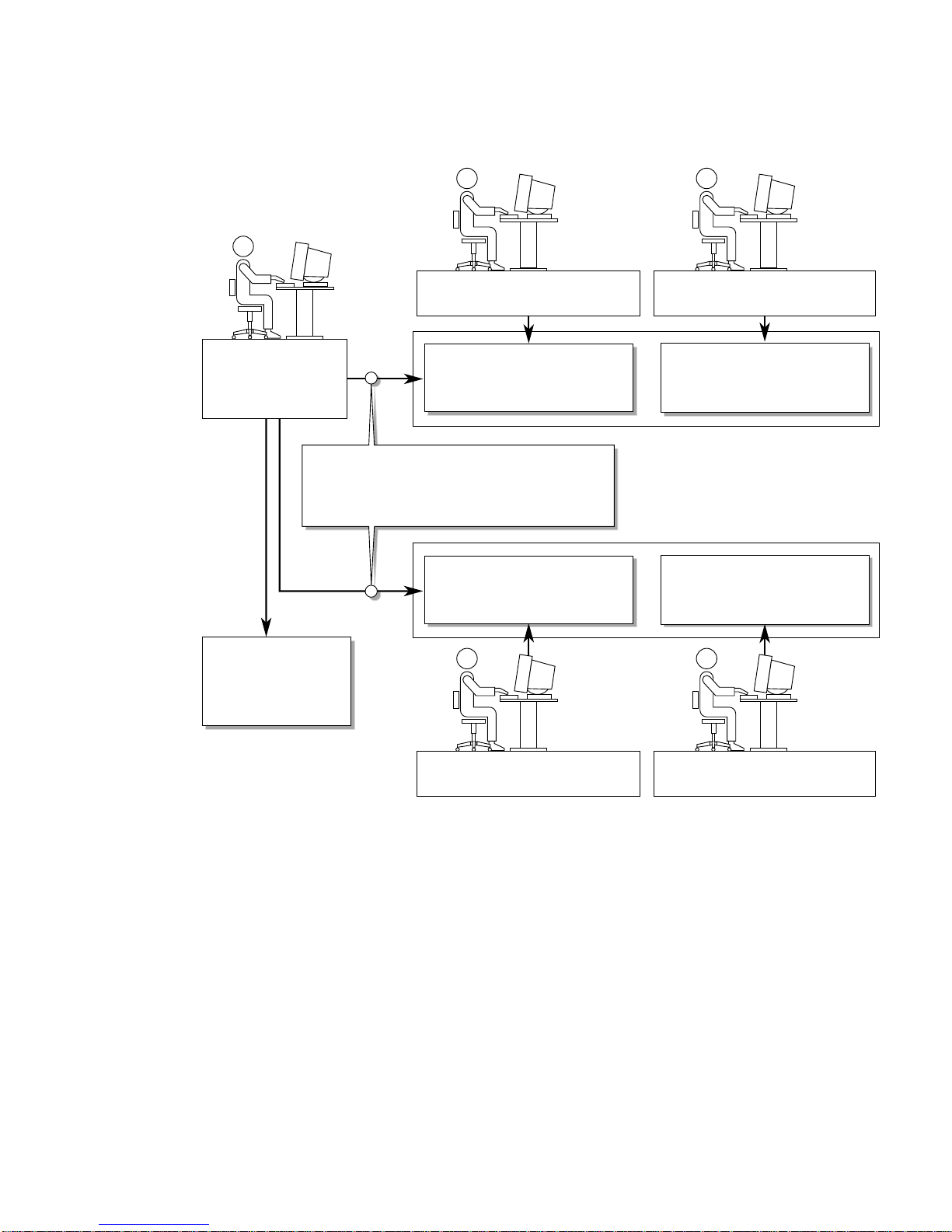
Domain A
administrator
Domain A
users
Platform
administrator
Platform shell or
console access
Domain A shell
or console access
If the platform administrator knows
or resets the domain passwords or if
the domain passwords are not set
Domain B shell
or console access
Domain B
administrator
Solaris operating
environment
access
Solaris operating
environment
access
Domain B
users
FIGURE 5-1 System With Domain Separation
Chapter 5 Security 63
Page 86
setkeyswitch Command
The Sun Fire 6800/4810/4800/3800 systems do not have a physical keyswitch. You
set the virtual keyswitch in each domain shell with the setkeyswitch command.
To secure a running domain, set the domain keyswitch to the secure setting. For
more information about setkeyswitch, refer to the online article, Securing the Sun
Fire Midframe System Controller available online at
http://www.sun.com/blueprints
With the keyswitch set to secure, the following restrictions occur:
■ Disables the ability to perform flashupdate operations on CPU/Memory boards
or I/O assemblies. Performing flashupdate operations on these boards should
only be done by an administrator who has platform shell access on the system
controller.
■ Ignores break and reset commands from the system controller. This is an
excellent security precaution. This functionality also ensures that accidentally
typing a break or reset command will not halt a running domain.
Solaris Operating Environment Security
For information on securing the Solaris operating environment, refer to the
following books and articles:
■ SunSHIELD Basic Security Module Guide (Solaris 8 System Administrator
Collection)
■ Solaris 8 System Administration Supplement or System Administration Guide: Security
Services in the Solaris 9 System Administrator Collection
■ Solaris security toolkit articles available online at
http://www.sun.com/blueprints
SNMP
The system controller uses SNMPv1, which is an insecure protocol. This means that
the SNMPv1 traffic needs to be kept on a private network, as described in the online
article, Securing the Sun Fire Midframe System Controller available online at
http://www.sun.com/blueprints
64 Sun Fire 6800/4810/4800/3800 Systems Platform Administration Manual • May 2002
Page 87

CHAPTER
6
Maintenance
This chapter explains how to perform the following procedures:
■ “Powering Off and On the System” on page 65
■ “Keyswitch Positions” on page 69
■ “Shutting Down Domains” on page 70
■ “Assigning and Unassigning Boards” on page 71
■ “Upgrading the Firmware” on page 75
■ “Saving and Restoring Configurations” on page 76
Powering Off and On the System
To power off the system, you must halt the Solaris operating environment in each
domain and power off each domain.
Note – Before you begin this procedure, make sure you have the following books.
Also, if you have a redundant system controller configuration, review “Conditions
That Affect Your SC Failover Configuration” on page 77, before you power cycle
your system.
■ Sun Fire 6800/4810/4800/3800 Systems Service Manual
■ Sun Hardware Platform Guide (available with your version of the Solaris operating
environment)
Powering Off the System
When you power off the system, power off all of the active domains. Then power off
the power grid(s). The last step is to power off the hardware.
65
Page 88

▼ To Power Off the System
1. Connect to the appropriate domain shell.
See “System Controller Navigation” on page 32.
2. Display the status of all domains. Type the following from the platform shell:
TABLE 6-1 Displaying the Status of All Domains With the showplatform -p status
Command
schostname:SC> showplatform -p status
Domain Solaris Nodename Domain Status Keyswitch
-------- ---------------- ------------- --------A Solaris nodename-a Active - Solaris on
B - Powered Off off
C - Powered Off standby
D - Powered Off standby
schostname:SC>
3. Complete these substeps for each active domain.
These substeps include halting the Solaris operating environment in each domain,
turning off the domain keyswitch, and disconnecting from the session.
a. Enter the domain console you want to power off.
See “Obtaining a Domain Shell or Console” on page 30.
b. If the Solaris operating environment is running, log in as root and halt the
operating environment.
Refer to the Sun Hardware Platform Guide, which is available with your Solaris
operating environment release.
You will see the OpenBoot PROM ok prompt when the Solaris operating
environment is shut down.
c. From the ok prompt, obtain the domain shell prompt.
i. Press and hold the CTRL key while pressing the ] key to get to the telnet>
prompt.
66 Sun Fire 6800/4810/4800/3800 Systems Platform Administration Manual • May 2002
Page 89
ii. At the telnet> prompt, type send break.
ok CTRL ]
telnet> send break
schostname:A>
The domain shell prompt is displayed.
d. Turn the domain keyswitch to the off position with the setkeyswitch off
command.
schostname:A> setkeyswitch off
e. Disconnect from the session by typing the disconnect command.
schostname:A> disconnect
4. Power off the power grid(s).
This step powers off the power supplies.
■ Access the platform shell.
See “Obtaining the Platform Shell” on page 28.
■ If you have a Sun Fire 6800 system, you must power off power grids 0 and 1.:
schostname:SC> poweroff grid0 grid1
Go to Step 5.
■ If you have a Sun Fire 4810/4800/3800 system, there is only one power grid,
grid 0. Power off power grid 0:
schostname:SC> poweroff grid0
5. Power off the hardware in your system.
Refer to the “Powering Off and On” chapter of the Sun Fire 6800/4810/4800/3800
Systems Service Manual.
Chapter 6 Maintenance 67
Page 90
▼ To Power On the System
1. Power on the hardware.
Refer to the “Powering Off and On” chapter of the Sun Fire 6800/4810/4800/3800
Systems Service Manual.
2. Access the system controller platform shell.
See “Obtaining the Platform Shell” on page 28.
3. Power on the power grids.
Powers on the power supplies. Complete the following substeps.
■ If you have a Sun Fire 6800 system, power on power grid 0 and power grid 1.
schostname:SC> poweron grid0 grid1
■ If you have a Sun Fire 4810/4800/3800 system, there is only one power grid, grid
0:
schostname:SC> poweron grid0
4. Boot each domain.
a. Access the domain shell for the domain you want to boot.
“Obtaining a Domain Shell or Console” on page 30.
b. Boot the domain with the system controller setkeyswitch on command.
schostname:A> setkeyswitch on
This command turns on the domain and boots the Solaris operating environment
if the OpenBoot PROM auto-boot? parameter is set to true and the OpenBoot
PROM boot-device parameter is set to the proper boot device.
Use the setupdomain command (OBP.auto-boot? parameter), which is run
from a domain shell, or the OpenBoot PROM setenv auto-boot? true
command to control whether the Solaris operating environment auto boots when
you turn the keyswitch on.
Go to Step 5.
68 Sun Fire 6800/4810/4800/3800 Systems Platform Administration Manual • May 2002
Page 91
Note – If the Solaris operating environment did not boot automatically, continue
with the Step c. Otherwise, go to Step 5.
The Solaris operating environment will not boot automatically if the OpenBoot
PROM auto-boot? parameter is set to false. You will see the ok prompt.
c. At the ok prompt, type the boot command to boot the Solaris operating
environment.
ok boot
After the Solaris operating environment is booted, the login: prompt is
displayed.
login:
5. To access and boot another domain, repeat Step 4.
Keyswitch Positions
Each domain has a virtual keyswitch with five positions: off, standby, on, diag, and
secure. The setkeyswitch command in the domain shell changes the position of
the virtual keyswitch to the specified value. The virtual keyswitch replaces the need
for a physical keyswitch for each domain. This command is also available, with
limited functionality, in the platform shell.
For command syntax, examples, descriptions of setkeyswitch parameters, and
results when you change the keyswitch setting, see the setkeyswitch command in
the Sun Fire 6800/4810/4800/3800 System Controller Command Reference Manual.
Caution – During the setkeyswitch operation, heed the following precautions:
Do not power off any boards assigned to the domain.
Do not reboot the system controller.
Chapter 6 Maintenance 69
Page 92

▼ To Power On a Domain
1. Access the domain you want to power on.
See “System Controller Navigation” on page 32.
2. Set the keyswitch to on, diag, or secure using the system controller
setkeyswitch command.
Shutting Down Domains
This section describes how to shut down a domain.
▼ To Shut Down a Domain
1. Connect to the domain console of the domain you want to shut down.
See “System Controller Navigation” on page 32.
From the domain console, if the Solaris operating environment is booted you will see
the % , #,orlogin: prompts.
2. If the Solaris operating environment is running, halt the Solaris operating
environment from the domain console as root.
Refer to the Sun Hardware Platform Guide, which is available with your Solaris
operating environment release.
3. Enter the domain shell from the domain console.
See “To Obtain the Domain Shell From the Domain Console” on page 32.
4. In the domain shell, type:
schostname:A> setkeyswitch off
5. If you need to completely power off the system, see “Powering Off and On the
System” on page 65.
70 Sun Fire 6800/4810/4800/3800 Systems Platform Administration Manual • May 2002
Page 93

Assigning and Unassigning Boards
When you assign a board to a domain, the board must be listed in the Access
Control List (ACL) for the domain. It cannot be already assigned to another domain.
The ACL is only checked when you assign a board to a domain. If the board is
assigned to a domain when the domain is active, the board is not automatically
configured to be part of that domain.
■ For an overview of steps on assigning and unassigning boards to or from a
domain with and without dynamic reconfiguration (DR), see
TABLE 6-3.
■ For complete step-by-step procedures not using dynamic reconfiguration, see “To
Assign a Board to a Domain” on page 72 and “To Unassign a Board From a
Domain” on page 74.
■ For procedures that use dynamic reconfiguration, refer to the Sun Fire 6800, 4810,
4800, and 3800 Systems Dynamic Reconfiguration User Guide.
TABLE 6-2 Overview of Steps to Assign a Board To a Domain
To Assign a Board To a Domain Using DR To Assign a Board To a Domain Not Using DR
TABLE 6-2 and
1. Assign the disconnected and isolated board to the
domain with the cfgadm -x assign command.
2. Use DR to configure the board into the domain.
Refer to the Sun Fire 6800, 4810, 4800, and 3800
Systems Dynamic Reconfiguration User Guide.
TABLE 6-3 Overview of Steps to Unassign a Board From a Domain
To Unassign a Board From a Domain Using DR To Unassign a Board From a Domain Not Using DR
1. Use DR to unconfigure the board from the domain.
Refer to the Sun Fire 6800, 4810, 4800, and 3800
Systems Dynamic Reconfiguration User Guide.
2. Unassign the board from the domain with the
cfgadm -c disconnect -o unassign
command.
1. Assign the board to the domain with the
addboard command.
2. Halt the Solaris operating environment in the
domain.
3. Shut down the domain with setkeyswitch
standby.
4. Turn on the domain with setkeyswitch on.
1. Halt the Solaris operating environment in the
domain.
2. Turn the keyswitch to standby mode with
setkeyswitch standby.
3. Unassign the board from the domain with the
deleteboard command.
4. Turn on the domain with setkeyswitch on.
Chapter 6 Maintenance 71
Page 94

▼ To Assign a Board to a Domain
Note – This procedure does not use dynamic reconfiguration (DR).
1. Enter the domain shell for the domain you want to assign the board to.
See “Obtaining a Domain Shell or Console” on page 30.
2. Type the showboards command with the -a option to find available boards that
can be used in the domain.
In the domain shell, the command output list boards that are in the current domain
and boards that are not yet assigned to a domain and are listed in the Access Control
List (ACL) for the current domain. You can assign any board listed that is not
currently part of the domain to the current domain.
CODE EXAMPLE 6-1 showboards -a Example Before Assigning a Board to a Domain
schostname:A> showboards -a
Slot Pwr Component Type State Status Domain
---- --- -------------- ----- ------ -----/N0/SB0 On CPU Board Active Passed A
/N0/IB6 On PCI I/O Board Active Passed A
If the board you want to assign to the domain is not listed in the showboards -a
output, complete the following substeps. Otherwise, go to Step 3.
a. Make sure that the board has not been assigned to another domain by running
the showboards command in the platform shell.
A board cannot be assigned to the current domain if it belongs to another domain.
b. Verify that the board is listed in the Access Control List (ACL) for the domain.
Use the showplatform -p acls command (platform shell) or the
showdomain -p acls command (domain shell).
c. If the board is not listed in the ACL for the desired domain, use the
setupplatform -p acls command from the platform shell to add the board
to the ACL for the domain.
See “To Configure Platform Parameters” on page 47.
72 Sun Fire 6800/4810/4800/3800 Systems Platform Administration Manual • May 2002
Page 95
3. Assign the proper board to the desired domain with the addboard command.
The board must be in the Available board state. For example, to assign
CPU/Memory board, sb2, to the current domain, type:
schostname:A> addboard sb2
The new board assignment takes effect when you change the domain keyswitch
from an inactive position (off or standby) to an active position (on, diag, or
secure) using the system controller setkeyswitch command.
Assigning a board to a domain does not automatically make that board part of an
active domain.
4. If the domain is active (the domain is running the Solaris operating environment,
the OpenBoot PROM, or POST), complete this step.
■ If the Solaris operating environment is running in the domain, log in as root to the
Solaris operating environment and halt it. For details on how to halt a domain
running the Solaris operating environment, refer to the Sun Hardware Platform
Guide.
■ If the OpenBoot PROM or POST is running, wait for the ok prompt.
a. Obtain the domain shell.
See “To Obtain the Domain Shell From the Domain Console” on page 32.
b. Shut down the domain. Type:
schostname:A> setkeyswitch standby
By setting the domain keyswitch to standby instead of off, the boards in the
domain do not need to be powered on and tested again. Setting the keyswitch to
standby also decreases downtime.
c. Turn the domain on. Type:
schostname:A> setkeyswitch on
Note – Rebooting the Solaris operating environment without using the
setkeyswitch command does not configure boards that are in the Assigned board
state into the active domain.
Chapter 6 Maintenance 73
Page 96

d. If your environment is not set to automatically boot the Solaris operating
environment in the domain after you turned the keyswitch on, boot the
operating environment by typing boot at the ok prompt.
ok boot
Note – Setting up whether the Solaris operating environment auto boots or not
when you turn the keyswitch on is done either with the setupdomain command
(OBP.auto-boot? parameter), which is run from a domain shell, or with the
OpenBoot PROM setenv auto-boot? true command.
▼ To Unassign a Board From a Domain
Note – This procedure does not use dynamic reconfiguration (DR).
Unassign a board from a domain with the deleteboard command. For a complete
description of the deleteboard command, see the Sun Fire 6800/4810/4800/3800
System Controller Command Reference Manual.
Note – When you unassign a board from a domain, the domain cannot not be
active. This means it must not be running the Solaris operating environment, the
OpenBoot PROM, or POST. The board you are unassigning must be in the Assigned
board state.
1. Halt the Solaris operating environment in the domain.
Refer to the Sun Hardware Platform Guide.
2. Enter the domain shell for the proper domain.
See “System Controller Navigation” on page 32.
3. Turn the domain keyswitch off with setkeyswitch off.
4. Type the showboards command to list the boards assigned to the current domain.
5. Unassign the proper board from the domain with the deleteboard command:
schostname:A> deleteboard sb2
74 Sun Fire 6800/4810/4800/3800 Systems Platform Administration Manual • May 2002
Page 97

6. Turn on the domain. Type:
schostname:A> setkeyswitch on
7. If your environment is not set to automatically boot the Solaris operating
environment in the domain after you turned the keyswitch on, boot the operating
environment by typing boot at the ok prompt.
ok boot
Upgrading the Firmware
The flashupdate command updates the firmware in the system controller and the
system boards (CPU/Memory boards and I/O assemblies). There is no firmware on
the Repeater boards. This command is available in the platform shell only. The
source flash image can be on a server or another board of the same type.
A complete description of this command, including command syntax and examples,
see the flashupdate command in the Sun Fire 6800/4810/4800/3800 System
Controller Command Reference Manual.
Note – Review the README and Install.info files before you upgrade the
firmware.
In order to upgrade the firmware from a URL, the firmware must be accessible from
a ftp or http URL. Before performing the flashupdate procedure read the
information in the “Description” section of the flashupdate command in the Sun
Fire 6800/4810/4800/3800 System Controller Command Reference Manual. The
“Description” section covers:
■ Steps to perform before you upgrade the firmware.
■ What to do if the images you installed are incompatible with the new images.
Caution – When you update the firmware on the system controller, update only one
system controller at a time, as described in the Install.info file. DO NOT update
both system controllers at the same time.
Chapter 6 Maintenance 75
Page 98

Saving and Restoring Configurations
This section describes when to use the dumpconfig and restoreconfig
commands.
Using dumpconfig
Use the dumpconfig command to save platform and domain settings after you
■ Complete the initial configuration of the platform and the domains
■ Modify the configuration, or change the hardware configuration
For an explanation of how to use this command, see “Saving the Current
Configuration to a Server” on page 50. For complete command syntax and examples
of this command, refer to the dumpconfig command in the Sun Fire
6800/4810/4800/3800 System Controller Command Reference Manual.
Using restoreconfig
Use the restoreconfig command to restore platform and domain settings.
For complete command syntax and examples of this command, refer to the
restoreconfig command in the Sun Fire 6800/4810/4800/3800 System Controller
Command Reference Manual.
76 Sun Fire 6800/4810/4800/3800 Systems Platform Administration Manual • May 2002
Page 99

CHAPTER
7
System Controller Failover
Sun Fire 6800/4810/4800/3800 systems can be configured with two system
controllers for high availability. In a high-availability system controller (SC)
configuration, one SC serves as the main SC, which manages all the system
resources, while the other SC serves as a spare. When certain conditions cause the
main SC to fail, a switchover or failover from the main SC to the spare is triggered
automatically, without operator intervention. The spare SC assumes the role of the
main and takes over all system controller responsibilities.
This chapter explains the following:
■ How SC Failover Works
■ SC Failover Prerequisites
■ Conditions That Affect Your SC Failover Configuration
■ How to Manage SC Failover
■ How to Recover After an SC Failover
How SC Failover Works
The SC failover capability is enabled by default on Sun Fire midrange servers that
have two System Controller boards installed. The failover capability includes both
automatic and manual failover. In automatic SC failover, a failover is triggered when
certain conditions cause the main SC to fail or become unavailable. In manual SC
failover, you force the switchover of the spare SC to the main.
The failover software performs the following tasks to determine when a failover
from the main SC to the spare is necessary and to ensure that the system controllers
are failover-ready:
■ Continuously checks the heartbeat of the main SC and the presence of the spare
SC.
77
Page 100

■ Copies data from the main SC to the spare SC at regular intervals so that the data
on both system controllers is synchronized if a failover occurs.
If at any time the spare SC is not available or does not respond, the failover
mechanism disables SC failover. If SC failover is enabled, but the connection link
between the SCs is down, failover remains enabled and active until the system
configuration changes. After a configuration change, such as a change in platform or
domain parameter settings, the failover mechanism remains enabled, but it is not
active (SC failover is not in a failover-ready state because the connection link is
down). You can check the SC failover state by using commands such as
showfailover or showplatform, as explained in “To Obtain Failover Status
Information” on page 83.
What Triggers an Automatic Failover
A failover from the main to the spare SC is triggered when one of the following
failure conditions occurs:
■ The heartbeat of the main SC stops.
■ The main SC is rebooted but it does not boot successfully.
■ A fatal software error occurs.
What Happens During a Failover
An SC failover is characterized by the following:
■ Failover event message
The SC failover event is logged in the platform message log file, which is viewed
on the console of the new main SC or through the showlogs command on the SC.
The information displayed indicates that a failover has occurred and identifies the
failure condition that triggered the failover.
CODE EXAMPLE 7-1 shows the type of information that appears on the console of
the spare SC when a failover occurs due to a stop in the main SC heartbeat:
CODE EXAMPLE 7-1 Messages Displayed During an Automatic Failover
Platform Shell - Spare System Controller
sp4-sc0:sc> Nov 12 01:15:42 sp4-sc0 Platform.SC: SC Failover: enabled and
active.
78 Sun Fire 6800/4810/4800/3800 Systems Platform Administration Manual • May 2002
 Loading...