


Sun Enterprise
Site Planning Guide
™
10000 System
Sun Microsystems, Inc.
4150 Network Circle
Santa Clara, CA 95054 U.S.A.
650-960-1300
Part No. 805-2914-15
March 2002, Revision A
Send comments about this document to: docfeedback@sun.com

Copyright 2002Sun Microsystems, Inc., 4150 NetworkCircle, SantaClara, CA 95054 USA. Allrights reserved.
This productor document is distributed underlicenses restrictingits use, copying, distribution, anddecompilation. No part of thisproduct or
document maybe reproducedin any form by anymeans without prior written authorizationof Sun and its licensors,if any. Third-party
software, includingfont technology, is copyrighted and licensed from Sunsuppliers.
Parts ofthe product may be derivedfrom BerkeleyBSD systems, licensed from the University ofCalifornia. UNIX is a registered trademark in
the U.S.and other countries, exclusively licensedthrough X/Open Company,Ltd.
Sun, SunMicrosystems, the Sun logo, AnswerBook2,docs.sun.com, and Solaris are trademarks, registered trademarks, or servicemarks of Sun
Microsystems, Inc.in the U.S. and othercountries. All SPARC trademarks are used under licenseand aretrademarks or registered trademarks
of SPARC International, Inc. in theU.S. and other countries. Products bearing SPARC trademarksare based upon an architecture developed by
Sun Microsystems,Inc. The Energy Star logo is aregistered trademarkof EPA
The OPENLOOK and Sun™ Graphical UserInterface was developed by SunMicrosystems, Inc.for its users and licensees.Sun acknowledges
the pioneeringefforts of Xerox in researching and developing the conceptof visual or graphical userinterfaces for the computer industry. Sun
holds anon-exclusive license from Xerox to the Xerox Graphical User Interface, which licensealso covers Sun’s licensees who implement OPEN
LOOK GUIsand otherwise comply with Sun’swritten license agreements.
Federal Acquisitions:Commercial Software—GovernmentUsers Subject to Standard License Terms and Conditions.
DOCUMENTATION IS PROVIDED “AS IS” AND ALL EXPRESS OR IMPLIED CONDITIONS, REPRESENTATIONS AND WARRANTIES,
INCLUDING ANY IMPLIED WARRANTY OF MERCHANTABILITY, FITNESS FOR A PARTICULAR PURPOSE OR NON-INFRINGEMENT,
ARE DISCLAIMED, EXCEPT TO THE EXTENT THAT SUCH DISCLAIMERS ARE HELD TO BE LEGALLY INVALID.
Copyright 2002Sun Microsystems, Inc., 4150 NetworkCircle, SantaClara, CA 95054 Etats-Unis. Tous droitsréservés.
Ce produitou document est distribué avecdes licences qui en restreignent l’utilisation, la copie, ladistribution, et la décompilation. Aucune
partie dece produit ou document nepeut êtrereproduite sousaucune forme, par quelque moyenque ce soit, sans l’autorisation préalable et
écrite deSun et de ses bailleursde licence, s’il y ena. Le logiciel détenu pardes tiers, et qui comprend la technologie relative aux polices de
caractères, estprotégé parun copyright et licencié pardes fournisseurs de Sun.
Des partiesde ce produit pourront être dérivées des systèmes BerkeleyBSD licenciés par l’Université deCalifornie. UNIX est une marque
déposée auxEtats-Unis et dans d’autres payset licenciée exclusivement par X/Open Company, Ltd.
Sun, SunMicrosystems, le logo Sun, AnswerBook2,docs.sun.com, et Solaris sont des marques defabrique ou des marques déposées, ou
marques deservice, de Sun Microsystems, Inc. aux Etats-Uniset dans d’autres pays. Toutes les marques SPARC sontutilisées sous licence et
sont desmarques de fabrique ou desmarques déposéesde SPARC International, Inc. aux Etats-Uniset dans d’autres pays. Les produits portant
les marquesSPARCsont basés sur une architecture développée parSun Microsystems,Inc.
L’interfaced’utilisation graphique OPEN LOOK etSun™ a été développée parSun Microsystems,Inc. pour ses utilisateurs etlicenciés. Sun
reconnaît lesefforts depionniers de Xerox pour la recherche et le développementdu concept des interfaces d’utilisationvisuelle ou graphique
pour l’industriede l’informatique. Sun détient unelicence non exclusive de Xerox sur l’interface d’utilisation graphique Xerox, cette licence
couvrant égalementles licenciés de Sun quimettent en place l’interface d’utilisationgraphique OPEN LOOK et quien outrese conforment aux
licences écritesde Sun.
Achats fédéraux: logiciel commercial - Lesutilisateurs gouvernementaux doivent respecter les conditions ducontrat de licence standard.
LA DOCUMENTATION EST FOURNIE “EN L’ETAT” ET TOUTES AUTRES CONDITIONS, DECLARATIONS ET GARANTIES EXPRESSES
OU TACITES SONT FORMELLEMENT EXCLUES, DANSLA MESURE AUTORISEE PAR LA LOI APPLICABLE, YCOMPRIS NOTAMMENT
TOUTE GARANTIE IMPLICITE RELATIVE A LA QUALITE MARCHANDE, A L’APTITUDE A UNE UTILISATION PARTICULIERE OU A
L’ABSENCE DE CONTREFAÇON.
Please
Recycle

Contents
Preface ix
1. Environmental Requirements 1-1
1.1 Basic Cooling Requirements 1-2
1.2 Expanded Current Draw and Cooling Requirements 1-5
2. Facility Power Requirements 2-1
2.1 Facility Power Quality Tolerances 2-1
2.2 Facility Power Requirements 2-3
3. Physical Specifications 3-1
3.1 System Components 3-1
3.2 Processor Cabinet and Component
Physical Specifications 3-3
3.3 Raised-Floor Installations 3-8
3.4 Planning Your Access Route 3-10
4. Network Planning 4-1
4.1 Network Connections 4-1
4.2 Domain Setup Information 4-6
5. Site Planning Checklists 5-1
Contents iii

5.1 System Components 5-1
5.2 Miscellaneous 5-1
5.3 Environmental Requirements 5-2
5.4 Facility Power Requirements 5-2
5.5 Physical Specifications 5-3
5.6 System Remote Services 5-3
5.7 Capacity On Demand 5-3
5.8 Access Route Requirements 5-4
5.9 Upgrade Planning 5-5
5.10 Installation Schedule 5-5
Index Index-1
iv Sun Enterprise 10000 System Site Planning Guide • March 2002

Figures
FIGURE P-1 Site Preparation Process x
FIGURE 2-1 System Power Connections 2-8
FIGURE 2-2 System Power Connections With Dual Grid Power Installation 2-9
FIGURE 3-1 Sample Sun Enterprise 10000 System Cabinet Configurations 3-2
FIGURE 3-2 Processor Cabinet Shipping Crate Dimensions 3-5
FIGURE 3-3 Sun Enterprise 10000 System Cabinet Dimensions—Top and Front Views 3-6
FIGURE 3-4 Sun Enterprise 10000 System Cabinet Clearance Dimensions—Top View 3-7
FIGURE 3-5 Sun Enterprise 10000 System Floor Cutout Diagram 3-9
FIGURE 4-1 Network Configuration—Base 4-3
FIGURE 4-2 Network Configuration With Redundant Control Board 4-4
FIGURE 4-3 Network Configuration With Redundant Control Board and Spare SSP 4-5
v

vi Sun Enterprise 10000 System Site Planning Guide • March 2002

Tables
TABLE 1-1 Environmental Requirements 1-2
TABLE 1-2 Processor Cabinet Electrical and Cooling Requirements 1-3
TABLE 1-3 I/O Electrical and Cooling Requirements 1-4
TABLE 1-4 Power Dissipation and Air Conditioning Worksheet 1-4
TABLE 1-5 Cooling Requirements Based on Number of System Boards 1-5
TABLE 2-1 Facility Power Quality Tolerances 2-2
TABLE 2-2 Facility Power Requirements 2-4
TABLE 2-3 Power Cord Requirements Worksheet 2-7
TABLE 3-1 Physical Specifications of the Processor Cabinet 3-3
TABLE 3-2 Physical Specifications of the System Service Processor 3-4
TABLE 3-3 Physical Specifications of the SSP Hubs 3-4
TABLE 3-4 Access Route Clearances 3-10
TABLE 4-1 Software Configuration Setup Parameters for FIGURE 4-1 4-7
TABLE 4-2 Software Configuration Setup Parameters for FIGURE 4-2 4-9
TABLE 4-3 Software Configuration Setup Parameters for FIGURE 4-3 4-11
TABLE 4-4 Network Configuration Worksheet 4-13
vii

viii Sun Enterprise 10000 System Site Planning Guide • March 2002

Preface
The Sun Enterprise 10000 System Site Planning Guide helps management and site
preparation personnel identify suitable environments for the Sun Enterprise™ 10000
system. It describes configurations, electrical requirements, power consumption,
environmental requirements, and remote support equipment.
Due to the amount of time required to plan and properly prepare a site for
installation of a Sun Enterprise 10000 system, you must fulfill all of the requirements
outlined in this manual before your equipment arrives. Your Sun Microsystems™
account manager is available to help. Use
installation.
Once the site is prepared, your account manager will physically verify the site while
completing the site planning checklists in Chapter 5.
FIGURE P-1 as a guide to plan for a system
ix
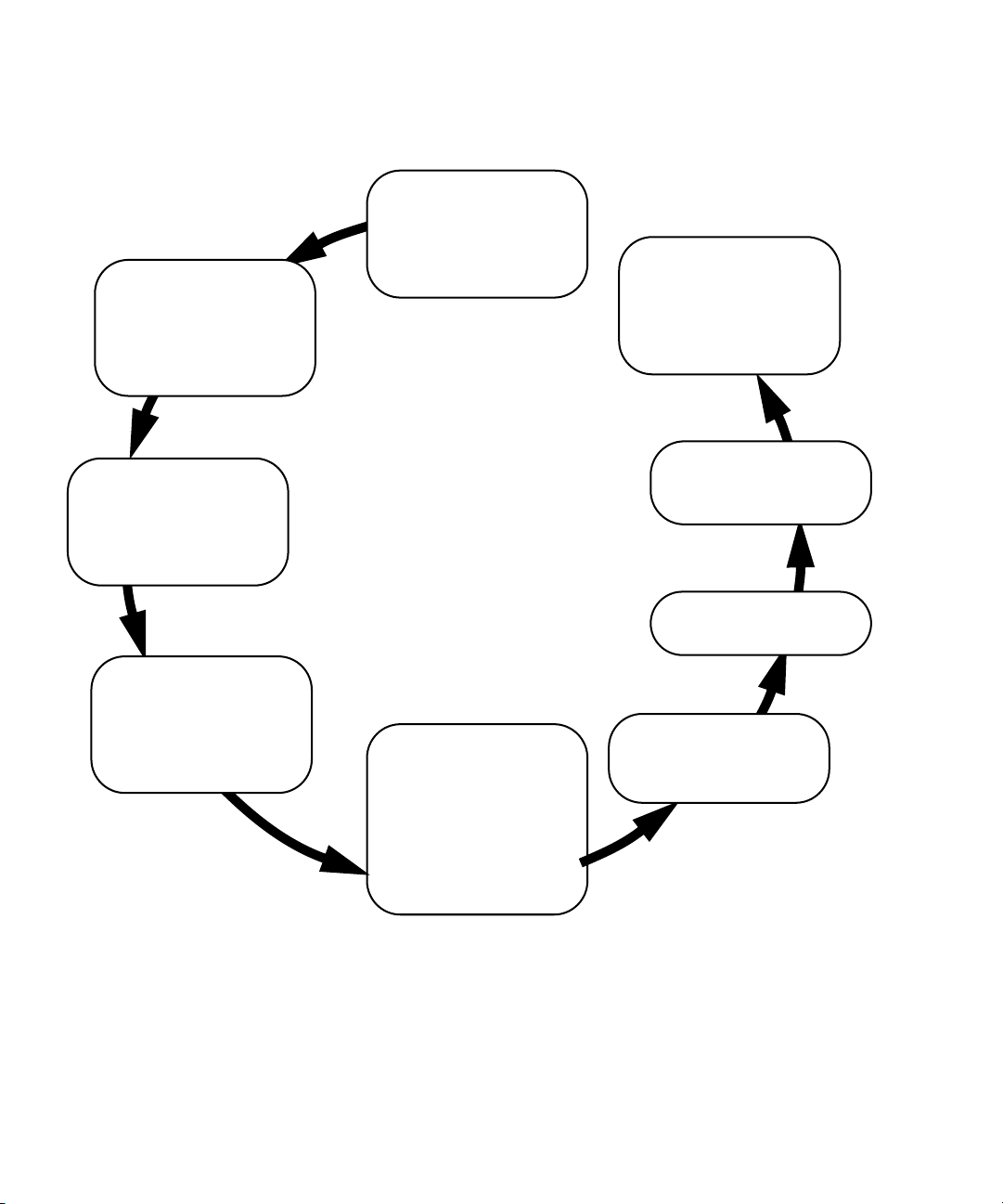
Determine the amount of
cooling needed by using
the worksheet.
(See
TABLE 1-4)
Start here
Obtain system
configuration from sales
engineer
Schedule the installation
date based on the
anticipated completion
date of site and
system arrival.
Determine the type and
quantity of receptacles
needed.
(See
TABLE 2-2 and
TABLE 2-3)
Determine the space
requirements and location of
the system.
(See
TABLE 3-1, TABLE 3-2,
FIGURE 3-3 and FIGURE 3-4)
FIGURE P-1 Site Preparation Process
Determine the type and
amount of networking
cables needed.
Determine all domain
information and complete
the worksheet.
(See Section 4.2 )
Complete and review all
worksheets and checklists.
Plan for equipment arrival.
(See Section 3.4 )
Schedule all necessary
modifications and obtain
any necessary hardware.
x Sun Enterprise 10000 System Site Planning Guide • March 2002

Typographic Conventions
Typeface Meaning Examples
AaBbCc123 The names of commands, files,
and directories; on-screen
computer output
AaBbCc123 What you type, when
contrasted with on-screen
computer output
AaBbCc123 Book titles, new words or
terms, words to be emphasized
Command-line variable;
replace with a real name or
value
Edit your .login file.
Use ls -a to list all files.
% You have mail.
% su
Password:
Read Chapter 6 in the User’s Guide.
These are called class options.
Yo u must be superuser to do this.
To delete a file, type rm filename.
Shell Prompts
Shell Prompt
C shell machine-name%
C shell superuser machine-name#
Bourne shell and Korn shell $
Bourne shell and Korn shell superuser #
Preface xi

Related Documents
The following documents contain topics that relate to the information
in the Sun Enterprise 10000 System Site Planning Guide.
Application Title
Service Sun Enterprise 10000 System Read Me First 805-2913
Sun Enterprise 10000 System Unpacking Guide 805-2915
Sun Enterprise 10000 System Overview 805-0310
Sun Enterprise 10000 Hardware Installation and De-Installation
Guide
Sun Enterprise 10000 System Service Manual 805-2917
Sun Enterprise 10000 System Service Reference I 805-3622
Sun Enterprise 10000 System Service Reference II 805-3623
Sun Enterprise 10000 System Service Processor Quick Reference 805-3827
Part
Number
805-4651
Accessing Sun Documentation Online
The docs.sun.comsmweb site enables you to access a select group of Sun technical
documentation on the Web. You can browse the docs.sun.com archive or search
for a specific book title or subject at:
http://docs.sun.com
xii Sun Enterprise 10000 System Site Planning Guide • March 2002

Sun Welcomes Your Comments
Sun is interested in improving its documentation and welcomes your comments and
suggestions. You can email your comments to Sun at:
docfeedback@sun.com
Please include the part number (805-2914-15) of your document in the subject line of
your email.
Preface xiii

xiv Sun Enterprise 10000 System Site Planning Guide • March 2002

CHAPTER
1
Environmental Requirements
The design of your environmental control system (such as computer room airconditioning units) must ensure that intake air to the system meets the requirements
specified in this section. Air enters the cabinet through the access panels and
through an air intake that is located underneath each cabinet. The exhaust air is
directed out the top of each cabinet. Overheating can occur if warm air is directed
underneath a cabinet or toward the access panels. The optimal parameters of
temperature and humidity shown in
for your equipment.
If the system is significantly colder [40°F(4°C) or colder] than the environment in
which you will install it, leave the system in its shipping crate (at its final
destination) for 24 hours to prevent thermal shock and condensation.
TABLE 1-1 will create the optimal environment
The remaining tables in this section provide air conditioning information for the
various components in the Sun Enterprise 10000 system. After determining your
configuration, use the tables to fill in the power and cooling section of the worksheet
in
TABLE 1-4. This will assist you in calculating your total system power consumption
(in watts) and the total amount system air conditioning required in British thermal
units (Btus). The amount of air conditioning required depends upon your
configuration.
1-1

TABLE 1-1 Environmental Requirements
Environmental
Factor Optimal Operating
Temperature 70° to 74°F
(21° to 23°C)
Relative Humidity 45% to 50% 20% to 80%
Altitude
1. For altitudes outside these ranges please consult your Sun Microsystems representative.
2. Temperature ramp rate not to exceed 68° F (20° C) per hour, humidity ramp rate not to exceed 30 percent relative humidity per hour.
3. Temperature ramp rate not to exceed 59° F (15° C) per hour, humidity ramp rate not to exceed 20 percent relative humidity per hour.
1
up to 10,000 ft (3,048 m) up to 10,000 ft (3,048 m) up to 40,000 ft (12,192 m)
50° to 88°F
(10° to 31°C)
(noncondensing)
27°C max wet bulb
2
Nonoperating
-40° to 149°F
(-40° to 65°C)
up to 93%
3
1.1 Basic Cooling Requirements
The Sun Enterprise 10000 system uses CMOS technology. CMOS is a dynamic
technology with fast transient current characteristics. Site planning requirements are
listed for the measurable current spikes with allowances for the calculable current
spikes. These systems have been designed to accommodate future system
performance upgrades and to prevent system failure should one of the power
supplies fail.
The dynamics of the power dissipation depend on the application and configuration.
The dynamics described in this manual are based on a rigorous code condition set
that has been verified in a lab environment. During these tests, all measurements
were taken with the latest-technology, high-speed current probe connected to the 48volt side of the power supply. The numbers were then backed out to account for
efficiency loss and power factor correction.
From a power perspective, after the rigorous code is invoked, the system becomes
very sensitive to the code based on processor and memory activity interaction and
can cause the power to swing hundreds of watts in either direction. For site
planning, rigorous code numbers are employed because systems must be able to
handle these potential high current conditions.
1-2 Sun Enterprise 10000 System Site Planning Guide • March 2002

Note – I/O power should be calculated on the number and types of trays being
configured. These numbers represent the maximum requirements, and as such may
not represent your configuration. Refer to your peripherals documentation for
additional information.
After the wall power has been determined (based on the number of system boards),
the ambient maintenance and environmental control must be calculated. It is
important that the site is able to accommodate the appropriate global environmental
variations. The values provided in this manual account for these variations.
This manual provides specifications for half- and full-configured systems (
TABLE 1-3, and TABLE 1-4). TABLE 1-5 provides specifications for systems configured
TABLE 1-2,
with fewer power cords. This can lead to problems because there is no failsafe
mechanism to indicate that more power is needed as new components are added. To
assist future upgrades, always provide sufficient power and cooling, not just for the
purchased system boards, but for the total number of power cords to be used.
For example, if planning for four system boards, a minimum of three power cords
are required. However, three power cords can effectively provide power for up to
eight system boards. Therefore, provide enough power and cooling for the
maximum configuration permitted by the three power cords: eight system boards or
7.215 kVA. When upgrading beyond the eight system boards, additional power
supplies will be needed, which will require new site planning for power and
cooling.
Note – The power cords provided with all Sun products, including the Sun
Enterprise 10000 system, are not classified as “plenum-rated.” According to UL and
CSA guidelines, the provided power cords can be routed and connected under a
raised tile floor space used for cooling air if the air is cooled by a dedicated system
separate from that used for personnel comfort and breathing.
TABLE 1-2 Processor Cabinet Electrical and Cooling Requirements
Power
Quantity of System Boards
Up to 8 6,136 20,656
Up to 16 11,041 37,165
Chapter 1 Environmental Requirements 1-3
Consumption
(watts)
Air Conditioning
(Btu/hr)
TABLE 1-3 I/O Electrical and Cooling Requirements
Cabinet
Processor cabinet I/O expansion area for three RSM
trays (maximum), or two Sun StorEdge D1000 arrays,
or 16 Unipack, or combination, and one or two Hubs
I/O expansion cabinet (at maximum configuration) 4,740 16,000
TABLE 1-4 Power Dissipation and Air Conditioning Worksheet
System Configuration Power Air Conditioning
Device Qty VA per unit Total VA
Processor cabinet configured
X
1
6,136
=
6,136
for 1-8 system boards
Additional requirements for a
X
4,905
=
processor cabinet configured
for 9-16 system boards
Processor Cabinet I/O
I/O Cabinets
System Service Processor
X
2,652
X
4,705
X
=
1
=
=
(SSP)
Power
(watts)
Air Conditioning
(Btu/hr)
2,520 8,566
Power
Factor Watts per unit
x .99 =
x .99 = x 3.4 =
x .95 = x 3.4 =
x .95 = x 3.4 =
x .95 = x 3.4 =
6,075
2
x 3.4 =
Btu/hr
20,654
Total Volt Amps Total Btu/hr
1. This number represents the maximum requirements, and as such may not accurately depict your configuration. Refer to the
documentation for your peripherals for additional information.
2. This number represents the maximum requirements. See Section 1.2, “Expanded Current Draw and Cooling Requirements” on
page 1-5” for specific requirements.
1-4 Sun Enterprise 10000 System Site Planning Guide • March 2002

1.2 Expanded Current Draw and Cooling Requirements
TABLE 1-5 provides detailed information based on incremental system board
requirements.
TABLE 1-5 Cooling Requirements Based on Number of System Boards
Number
of
system
boards
Number of front
end power
supplies for N+2
redundancy
1
Number of 30
amp single
phase service
2
cords
System
with
power
supplies
and fans
(VA)
1 4 2 2,311
System
board
(VA)
3
479 2.789 2.761 9.389
Service
requirement
system (kVA)
System
power
load plus
efficiency
loss
(kW)
Cooling
requirement
system
(Btu/hr)
2 4 2 2,311 956 3.267 3.235 10.997
3 5 3 2,311 1,434 3.745 3.708 12.608
4 5 3 2,311 1,913 4.224 4.182 14.218
5 5 3 2,311 2,391 4.702 4.655 15.826
6 6 3 2,311 2,869 5.180 5.128 17.437
7 6 3 2,311 3,347 5.658 5.601 19.045
8 6 3 2,311 3,825 6.136 6.075 20.656
4
9 7 4 3,390
4,304 7.694 7.617 25.898
10 7 4 3,390 4,782 8.172 8.090 27.506
11 7 4 3,390 5,260 8.650 8.563 29.117
12 8 4 3,390 5,739 9.129 9.037 30.728
13 8 4 3,390 6,216 9.606 9.510 32.336
14 8 4 3,390 6,695 10.085 9.984 33.946
15 8 4 3,390 7,173 10.563 10.457 35.555
16 8 4 3,390 7,651 11.041 10.931 37.165
1. The Dual Grid Power configuration has 16 power supplies. The cooling requirements remain the same as for eight power sup-
plies.
2. See page 1-3.
3. System configured for 1-8 system boards.
4. System configured for 9-16 system boards.
Chapter 1 Environmental Requirements 1-5

1-6 Sun Enterprise 10000 System Site Planning Guide • March 2002

CHAPTER
2
Facility Power Requirements
To prevent catastrophic failures, the design of your power system must ensure that
adequate power is provided to your Sun Enterprise 10000 system. All power circuits
that supply power to the Sun Enterprise 10000 system should be supplied by
dedicated electrical distribution panels. Electrical work and installations must
comply with applicable local, state, or national electrical codes.
Sun Microsystems makes every effort to minimize the effects of power failures and
interruptions to the hardware. However, if the computer equipment is subjected to
repeated power interruptions and fluctuations, it will be susceptible to a higher
component failure rate than would result from using a stable power source.
Consider installing an uninterruptable power supply (UPS) to reduce the possibility
of component failure.
2.1 Facility Power Quality Tolerances
The quality of the incoming power can be instrumental in maintaining appropriate
conditions and avoiding unplanned outages. Some factors affecting power quality
are listed below.
■ high frequency
■ high amplitude noise
■ high ground currents
■ low power factors
■ surges or sags in voltage
■ harmonic distortion
Numerous other factors can also affect correct functioning of electronic components.
TABLE 2-1 is a guide regarding the tolerances for power quality for the Sun Enterprise
10000 system.
2-1

TABLE 2-1 Facility Power Quality Tolerances
Environmental Attribute Limit Components Affected and Comments
Input voltage 190–254 VAC
All system electrical components
Single Phase
Power frequency 47–63 Hz
Line frequency 0.3% Disk packs, tape drives, regulators
Rate of frequency
0.3 Hz/s Disk packs
change
Over/under voltage 3% Unregulated power supplies
Phase imbalance 3% max Polyphase rectifiers, motors
Power source –
tolerance to lowpower factor
Tolerance to high
steady-state peak
<0.6 lagging or
0.9 leading
Indirectly limits power source or requires
greater capacity unit with reduced overall
efficiency
>2.5 peak/rms 1.414 normal; departures cause wave shape
distortion
current
Voltage harmonics 5% max total
Voltage regulators, signal circuits
3% largest
DC load current
capability of power
As low as 0.5% Half-wave rectifier load can saturate some
power sources and trip circuits
source
Voltage deviation
3–5% Affects regulators, signal circuits
from sine wave
Voltage modulation 1% max Voltage regulators, servo motors
Transient surges/sags +5%, -5% Regulated power, motor torques
Transient impulses Varies:
200 - 500V
Memory, disks, tape drives having data
transfer rates, low-level data signals
typical
RFI/EMI and “tone
bursts” – normal and
Varies widely:
0.3 typical
Same as above
common modes
Ground currents
1
0.0035A or less May trip GFI devices, violate code, introduce
noise in signal circuits
1. Earth leakage current values for Sun Enterprise 10000 system are:
22.4mA @ 254VAC, 60 Hz - standard power configuration
44.8mA @ 254VAC, 60 Hz - dual power grid configuration
2-2 Sun Enterprise 10000 System Site Planning Guide • March 2002

2.2 Facility Power Requirements
Each Sun Enterprise 10000 system cabinet and peripheral cabinet requires its own
customer-supplied circuit breaker and receptacles.
■ The Sun Enterprise 10000 system cabinet requires up to four receptacles for the
main system components (eight with the Dual Grid Power installation) and an
additional receptacle for the AC sequencer (two with the Dual Grid Power
installation) that provides power to the peripherals.
■ Each peripheral cabinet requires one or more receptacles.
■ An International Electrotechnical Commission 309 (IEC 309) connector, supplied
by Sun Microsystems, connects power to the system.
Each piece of support equipment requires its own customer-supplied circuit breaker
and receptacle(s).
■ The System Service Processor (SSP) requires one customer-supplied receptacle per
unit.
■ The modem requires one customer-supplied receptacle per unit.
TABLE 2-2 lists the electrical specifications for the processor cabinet or peripheral
cabinet, the SSP, and the optional modem. See
possible system power connections.
FIGURE 2-1 for an illustration of
Chapter 2 Facility Power Requirements 2-3

TABLE 2-2 Facility Power Requirements
Electrical Service Specification
Sun Enterprise 10000 system cabinet for
1-8 system boards requires:
Note: Does not include I/O area.
Voltage 190–254 VAC, single phase
Frequency 47–63 Hz
Circuit breaker (1 per AC input module) Three 30-amp breakers
Current 7412 VA (maximum for three line cords or six for Dual
Grid Power installation)
Total harmonic distortion (THD) Less than 9% at full load
Less than 1.07% at the third harmonic
Power cords 14.7 ft (4.5 m) connector-compatible drop cord [allow for
approximately 8 ft (2.5 m) of usable length]
Receptacle: North America and Japan (three
NEMA #L6-30R, single phase, 32 amps
required or six for Dual Grid Power installations)
Receptacle: International (three required or six for
Dual Grid Power installation)
IEC 309, single phase, 32 amps
2-4 Sun Enterprise 10000 System Site Planning Guide • March 2002

TABLE 2-2 Facility Power Requirements (Continued)
Electrical Service Specification
Sun Enterprise 10000 system cabinet for
9-16 system boards requires:
Note: Does not include I/O area.
Voltage 190–254 VAC, single phase
Frequency 47–63 Hz
Circuit breaker (1 per AC input module) Four 30-amp breakers
(Eight 30-amp breakers with Dual Grid Power
installation)
Current 13,592 VA (maximum for four line cords or eight for
Dual Grid Power installation)
Total harmonic distortion (THD) Less than 9% at full load
Less than 1.07% at the third harmonic
Power cords 14.7 ft (4.5 m) connector-compatible drop cord [allow for
approximately 8 ft (2.5 m) of usable length]
Receptacle: North America and Japan (four
NEMA #L6-30R single phase, 32 amps
required)
Receptacle: International (four required)
Processing cabinet AC sequencer requires:
IEC 309 single phase, 32 amps
Voltage 190–254 VAC, single phase
Frequency 47–63 Hz
Circuit breaker 30 amps
Current 24 amps
Power cord (one or more required;
configuration-dependent)
Receptacle: North America and Japan
Receptacle: International
14.7 ft (450 cm) connector-compatible drop cord [allow
for approximately 8 ft (2.5 m) of usable length]
NEMA #L6-30R single phase, 32 amps
IEC 309 single phase, 32 amps
Chapter 2 Facility Power Requirements 2-5

TABLE 2-2 Facility Power Requirements (Continued)
Electrical Service Specification
Peripheral cabinet AC sequencer requires:
Voltage 190–254 VAC, single phase
Frequency 47–63 Hz
Circuit breaker 30 amps
Current 24 amps (for each line cord)
Total harmonic distortion (THD) Configuration-dependent
Power cord (one or more required;
configuration dependent)
Receptacle: North America and Japan
14.7 ft (4.5 m) connector-compatible drop cord [allow for
approximately 8 ft (250 cm) of usable length]
NEMA #L6-30R single phase, 32 amps
Receptacle: International
SSP requires:
IEC 309 single phase, 32 amps
Voltage 95–130 VAC or 190–254 VAC, single phase
Frequency 50 or 60 Hz
Circuit breaker 15 amps
Power cord Refer to the SSP manual for your country
2-6 Sun Enterprise 10000 System Site Planning Guide • March 2002

TABLE 2-2 Facility Power Requirements (Continued)
Electrical Service Specification
Optional modem requires:
Voltage: 100–120 VAC, single phase
Frequency 60 Hz
Circuit breaker 15 amps
Power consumption See
TABLE 1-4 for a detailed worksheet
Power cord (one) 6 ft (1.8 m) connector-compatible drop cord
Receptacle: North America (one) NEMA #5-15R or equivalent
TABLE 2-3 Power Cord Requirements Worksheet
Device Qty
AC input
modules
1
AC sequencer
in Sun
Enterprise
10000 system
2
cabinet
AC sequencers
in external
I/O cabinets
Other
30-amp devices
Total number of
30 amp single-phase
power receptacles needed
Number of
30-amp
Single-phase
Power Cords
Per Device Qty Device Qty
Number of
15-amp
Single-phase
Power Cords
Per Device Qty
x 1 = Modem x 1 =
x 1 = SSP
x = Customer-
3
x=
x1 =
provided hubs
x = Other
x=
15-amp devices
Total number of
15 amp single-phase
power receptacles needed
1. Typically three or four. Eight required for Dual Grid Power installation (four for each independent power source).
2. One or two.
Chapter 2 Facility Power Requirements 2-7

3. Typically one cord. Two cords are necessary to support SSP with Dual Grid Power capability.
Front
Main SSP
Spare SSP
SSP Hub 0
SSP Hub 1
Back
Required power connections
Configuration-dependent power connections
FIGURE 2-1 System Power Connections
2-8 Sun Enterprise 10000 System Site Planning Guide • March 2002
I/O Cabinet(s)

SSP
Power grid A
Front
Peripheral cabinet(s)
(optional)
Power grid B
FIGURE 2-2 System Power Connections With Dual Grid Power Installation
Rear
Chapter 2 Facility Power Requirements 2-9

2-10 Sun Enterprise 10000 System Site Planning Guide • March 2002

CHAPTER
3
Physical Specifications
This chapter describes Sun Enterprise 10000 system components and the weights
and dimensions of the packed and unpacked processor cabinet.
3.1 System Components
The Sun Enterprise 10000 system consists of one or more air-cooled cabinets that are
configured to meet customer-specified requirements. Minimum configurations use
only one cabinet which houses system components as well as peripherals. System
components include:
■ System board
■ SBus boards
■ Processor modules
■ Memory SIMMs
■ Centerplane
■ Centerplane support board
■ Control board
■ Power and cooling subsystems
Systems that are ordered with eight or less system boards may have any
combination of boards located in the front and rear of the chassis. If the boards are
not located in just one side of the chassis, then a full complement of fans, front and
rear, are required. The number of system boards determines how many processors,
memory, and I/O modules can be configured into the system. The Dual Grid Power
option (if installed) requires 8 AC input modules and 16 power supplies.
Multiple-cabinet configurations (
FIGURE 3-1) could include additional peripheral
cabinets. The only limiting factor for the number of peripheral cabinets is the
maximum permissible length of SCSI cabling. Peripheral cabinets house additional
I/O disk or tape subsystems. Additionally, each peripheral cabinet contains AC
distribution subsystems for use with the I/O subsystems.
3-1

To determine the space, cooling, and power requirements, determine what system
and I/O components will be used in your system. To begin the process of preparing
the site for your Sun Enterprise 10000 system, record your configuration on the
worksheet on
TABLE 1-4.
Sample configuration A
Sample configuration B
Sample configuration C
FIGURE 3-1 Sample Sun Enterprise 10000 System Cabinet Configurations
Note – Only one processor cabinet is used per system configuration; all other
cabinets are peripheral expansion cabinets. Additional peripheral expansion cabinets
may be used, provided SCSI cable length requirements are not compromised. The
processor cabinet may be located in any position within the system configuration.
3-2 Sun Enterprise 10000 System Site Planning Guide • March 2002

3.2 Processor Cabinet and Component Physical Specifications
TABLE 3-1 Physical Specifications of the Processor Cabinet
Characteristics Specifications
Shipping height
Shipping width
Shipping depth
Shipping weight
(maximum per
cabinet)
Height 70.0 in. (1778 mm)
Width 38.25 in. (971.55 mm)
Depth 49.94 in. (1268.48 mm)
Weight (fully loaded): 2,000 lbs (909 kg)
System board 26.4 lbs (12.0 kg)
AC input module 15.6 lbs (7.1 kg)
Power supply 9.9 lbs (4.5 kg)
Access requirement
for front and rear
78.75 in. (2000.3 mm)
48.75 in. (1238.3 mm)
61.25 in. (1555.8 mm)
2,200 lbs (1000 kg)
16.00 in. (406 mm) if no peripheral is over 20 in. (508 mm).
If a peripheral is over 20 in. (508 mm), add additional
access space to accommodate the excess length.
Chapter 3 Physical Specifications 3-3

TABLE 3-2 Physical Specifications of the System Service Processor
Characteristics Specifications
Height
Width
Depth
Weight
TABLE 3-3 Physical Specifications of the SSP Hubs
Characteristics Specifications
Height
Width
Depth
FIGURE 3-2 shows the dimensions of the Sun Enterprise 10000 system shipping crate.
FIGURE 3-3 shows the dimensions of the unpacked Sun Enterprise 10000 system
19.85 in. (504 mm)
20.00 in. (508 mm)
25.50 in. (648 mm)
79 lbs (36 kg)
1.00 in. (25 mm)
9.0 in. (229 mm)
5.5 in. (140 mm)
cabinet.
FIGURE 3-4 shows the clearance dimensions of the Sun Enterprise 10000 system.
See
TABLE 2-2 for processor cabinet and peripheral cabinet electrical specifications
and receptacle information.
3-4 Sun Enterprise 10000 System Site Planning Guide • March 2002

78.75 in.
2000.25 mm
24.00 in.
609.60 mm
45.50 in.
1155.70 mm
8.00 in.
203.20 mm
32.00 in.
812.80 mm
61.25 in.
1555.75 mm
FIGURE 3-2 Processor Cabinet Shipping Crate Dimensions
48.75 in.
1238.25 mm
Chapter 3 Physical Specifications 3-5

Top view
Front view
70.0 in.
1778.0 mm
49.94 in.
1268.48 mm
FIGURE 3-3 Sun Enterprise 10000 System Cabinet Dimensions—Top and Front Views
3-6 Sun Enterprise 10000 System Site Planning Guide • March 2002
33.5 in.
850.9 mm
38.25 in.
971.55 mm

76.99 in.
1955.55 mm
45.16 in.
1147.06 mm
34.87 in.
885.70 mm
38.25 in.
971.55 mm
FIGURE 3-4 Sun Enterprise 10000 System Cabinet Clearance Dimensions—Top View
Note – For any peripheral tray in the processor cabinet over 20 in. (508 mm) in
length, allow additional space for access in front of the access doors on the side
where the peripheral will be installed.
Chapter 3 Physical Specifications 3-7

3.3 Raised-Floor Installations
The optimal raised-floor installation provides a convenient way to duct cooling air
and to route power and communication cabling. If planning to install your system
on a raised floor, ensure that sufficient cooling will be available to the system.
Note – The power cords provided with all Sun products, including the Product
Name, are not classified as “plenum-rated.” According to UL and CSA guidelines,
the provided power cords can be routed and connected under a raised tile floor
space used for cooling air if the air is cooled by a dedicated system separate from
that used for personnel comfort and breathing.
The computer room floor must be able to support the weight of the system cabinets
TABLE 3-1). Each cabinet rests on four feet that concentrate the weight of the
(see
cabinet on a small surface area.
Place perforated floor panels or floor grilles at the base of the system, directly under
it.
FIGURE 3-5 illustrates the floor cutouts for cables and suggested locations for
perforated floor panels or floor grilles. Use the floor layout diagram of the proposed
location shown in
Note – For best performance, maximize the amount of cool air that is below the air-
intake screen.
FIGURE 3-5 to determine the exact area required.
The raised-floor height should be at least 12 in. (305 mm). If you have questions
concerning the structural capabilities of your floor, contact a qualified structural
engineer. If you are not installing your system on a raised floor, use flat cable covers
to protect cables and to protect personnel from a tripping hazard.
3-8 Sun Enterprise 10000 System Site Planning Guide • March 2002

40.1 in.
1018.10 mm
38.25 in.
971.55 mm
33.54 in.
851.79 mm
29.76 in.
755.90 mm
26.38 in.
670.05 mm
23.00 in.
584.20 mm
18.19 in.
461.96 mm
49.94 in.
1268.48 mm
45.2 in.
1147.90 mm
41.2 in.
1046.30 mm
36.7 in.
932.25 mm
Air-intake screen on bottom of cabinet
Cable access area (2 places)
Caster swivel radius (4 places) 2.4 in. 61.91 mm
Leveling pad diameter (4 places) 1.7 in. 42.9 mm
Styling panel
FIGURE 3-5 Sun Enterprise 10000 System Floor Cutout Diagram
Chapter 3 Physical Specifications 3-9

3.4 Planning Your Access Route
If your existing loading dock meets height or ramp requirements for a standard
freight truck, you can use a pallet jack to unload the system. If not, you must
provide a standard forklift
request the system be shipped in a truck with a lift gate.
See
FIGURE 3-2 for an illustration of the Sun Enterprise 10000 system cabinet shipping
crate and its dimensions. Other cabinets will be shipped in separate crates. A pallet
jack is required to move each shipping crate to the system location.
Leave each system cabinet in its shipping crate until it reaches its final destination. If
the crate does not fit through the planned access route, you can partially disassemble
the crate.
The entire access route to your computer room should be free of raised floor patterns
that could cause vibration. The access route must meet the following requirements.
1
or other means to unload the system. Alternatively,
TABLE 3-4
Minimum door height 80.00 in.
Minimum hallway and
door width
Maximum incline 15° 15° 15°
1. A standardforklift has a maximum outside tine dimension of 27 in. (685.8 mm)and a minimum inside tine
dimension of 15 in. (381 mm).
Access Route Clearances
With
Shipping Pallet
(2032.0 mm)
49.0 in.
(1244.6 mm)
Without Shipping Pallet
With Styling Panel Without Styling Panel
71.00 in. (1803 mm) 71.00 in. (1803 mm)
42.0 in. (1066.8 mm) 36.0 in. (914.4 mm)
3-10 Sun Enterprise 10000 System Site Planning Guide • March 2002

CHAPTER
4
Network Planning
This section provides sample network configurations and details for setting up
domains.
4.1 Network Connections
The Sun Enterprise 10000 system requires 10BASE-T or 100BASE-T Ethernet
connections on the customer network for the SSP and each host domain.
Additional Ethernet connections will be required if any of the following Sun
Enterprise 10000 options are ordered:
■ Optional redundant control board
■ Optional redundant SSP
■ Additional domains
■ Alternate pathing (AP)
To prevent general purpose Ethernet traffic from negatively affecting the SSP-to-Sun
Enterprise 10000 system host communication, comply with the following
configuration rules:
■ Connect the SSP and control boards by a private 10BASE-T network (separate
subnets). This will connect the one (or two) SSPs with the one (or two) control
boards.
■ Connect the SSP and each of the host domains through a second network. To
facilitate net booting a domain from the SSP, the network between the domain
and the SSP must be either 10BASE-T or 100BASE-T Ethernet.
4-1

FIGURE 4-1, FIGURE 4-2, and FIGURE 4-3 illustrate three possible network
configurations. All configurations use the hubs that are packaged with the control
boards during manufacturing and the SSP that is pre-configured with an additional
quad Fast Ethernet card. However, customer networks and hubs are the site owner ’s
responsibility.
4-2 Sun Enterprise 10000 System Site Planning Guide • March 2002

dom_subnet
To Customer Network
Customer Hub
Sun Enterprise 10000
Domain 16Domain 1
Control board 0
cb0_subnet
10BASE-T
10BASE-T or 100BASE-T
FIGURE 4-1 Network Configuration—Base
SSP Hub 0
SSP
Built-in port
le0
QFE card
hme0
Chapter 4 Network Planning 4-3

dom_subnet
To Customer Network
Customer Hub
Sun Enterprise 10000 system
Control board 0
cb0_subnet
le0
hme0
Domain 1
SSP Hub 0
Built-in port
SSP
QFE card
Domain 16
Control board 1
SSP Hub 1
cb1_subnet
hme1
10BASE-T
0BASE-T or 100BASE-T
FIGURE 4-2 Network Configuration With Redundant Control Board
4-4 Sun Enterprise 10000 System Site Planning Guide • March 2002

dom_subnet
To Customer Network
Customer Hub
Sun Enterprise 10000 system
cb0_subnet
Main SSP
Built-in port
le0
hme1
QFE card
hme0
10BASE-T
10BASE-T or 100BASE-T
Domain 1
Control board 0
SSP Hub 0
Domain 16
Control board 1
SSP Hub 1
Spare SSP
Built-in port
QFE card
cb1_subnet
le0
hme1
hme0
FIGURE 4-3 Network Configuration With Redundant Control Board and Spare SSP
Chapter 4 Network Planning 4-5

4.2 Domain Setup Information
The following information must be determined prior to installation of the Sun
Enterprise 10000 system. Most of this information is network-related and can only be
provided by the customer. Therefore, fill in the spaces in the appropriate worksheet
so that this information can be referred to during the software setup procedure.
■ Use TABLE 4-1 with FIGURE 4-1.
■ Use TABLE 4-2 with FIGURE 4-2.
■ Use TABLE 4-3 with FIGURE 4-3.
TABLE 4-4 provides a more graphic illustration of how the network parameters are
connected. This can be used as an alternative to any of the other
configuration setup parameter worksheets.
Note – The domains and SSP may require additional host names, IP addresses, and
netmasks if you are planning to configure a private network.
software
4-6 Sun Enterprise 10000 System Site Planning Guide • March 2002

TABLE 4-1 Software Configuration Setup Parameters for FIGURE 4-1
Platform Name
1
:
Domain 1
(Sun Enterprise 10000 Host)
Domain 2
(Sun Enterprise 10000 Host)
Domain 3
(Sun Enterprise 10000 Host)
Domain 4
(Sun Enterprise 10000 Host)
Domain 5
(Sun Enterprise 10000 Host)
Domain 6
(Sun Enterprise 10000 Host)
Domain 7
(Sun Enterprise 10000 Host)
Domain 8
(Sun Enterprise 10000 Host)
Domain 9
(Sun Enterprise 10000 Host)
Host Name IP Address Netmask Value
Domain 10
(Sun Enterprise 10000 Host)
Domain 11
(Sun Enterprise 10000 Host)
Domain 12
(Sun Enterprise 10000 Host)
Domain 13
(Sun Enterprise 10000 Host)
Domain 14
(Sun Enterprise 10000 Host)
Domain 15
(Sun Enterprise 10000 Host)
Domain 16
(Sun Enterprise 10000 Host)
Chapter 4 Network Planning 4-7

Software Configuration Setup Parameters for FIGURE 4-1 (Continued)
Host Name IP Address Netmask Value
Platform Name
1
:
TABLE 4-1
Control Board 0 (CB0)
SSP (le0 to private hub 0)
SSP (hme0 to customer hub)
NIS/NIS+ Domain (if applicable)
DNS Domain (if applicable)
1. The platform name is a logical name given to a Sun Enterprise 10000 system. A platform name does not correspond to any host on
the network.
4-8 Sun Enterprise 10000 System Site Planning Guide • March 2002

TABLE 4-2 Software Configuration Setup Parameters for FIGURE 4-2
Platform Name
1
:
Domain 1
(Sun Enterprise 10000 Host)
Domain 2
(Sun Enterprise 10000 Host)
Domain 3
(Sun Enterprise 10000 Host)
Domain 4
(Sun Enterprise 10000 Host)
Domain 5
(Sun Enterprise 10000 Host)
Domain 6
(Sun Enterprise 10000 Host)
Domain 7
(Sun Enterprise 10000 Host)
Domain 8
(Sun Enterprise 10000 Host)
Domain 9
(Sun Enterprise 10000 Host)
Host Name IP Address Netmask Value
Domain 10
(Sun Enterprise 10000 Host)
Domain 11
(Sun Enterprise 10000 Host)
Domain 12
(Sun Enterprise 10000 Host)
Domain 13
(Sun Enterprise 10000 Host)
Domain 14
(Sun Enterprise 10000 Host)
Domain 15
(Sun Enterprise 10000 Host)
Domain 16
(Sun Enterprise 10000 Host)
Chapter 4 Network Planning 4-9

Software Configuration Setup Parameters for FIGURE 4-2 (Continued)
Host Name IP Address Netmask Value
Platform Name
1
:
TABLE 4-2
Control Board 0 (CB0)
Control Board 1 (CB1)
SSP (le0 to private hub 0)
SSP (hme0 to customer hub)
SSP (hme1 to private hub 1)
NIS/NIS+ Domain (if applicable)
DNS Domain (if applicable)
1. The platform name is a logical name given to a Sun Enterprise 10000 system. A platform name does not correspond to any host on
the network.
4-10 Sun Enterprise 10000 System Site Planning Guide • March 2002

TABLE 4-3 Software Configuration Setup Parameters for FIGURE 4-3
Platform Name
1
:
Domain 1
(Sun Enterprise 10000 Host)
Domain 2
(Sun Enterprise 10000 Host)
Domain 3
(Sun Enterprise 10000 Host)
Domain 4
(Sun Enterprise 10000 Host)
Domain 5
(Sun Enterprise 10000 Host)
Domain 6
(Sun Enterprise 10000 Host)
Domain 7
(Sun Enterprise 10000 Host)
Domain 8
(Sun Enterprise 10000 Host)
Domain 9
(Sun Enterprise 10000 Host)
Host Name IP Address Netmask Value
Domain 10
(Sun Enterprise 10000 Host)
Domain 11
(Sun Enterprise 10000 Host)
Domain 12
(Sun Enterprise 10000 Host)
Domain 13
(Sun Enterprise 10000 Host)
Domain 14
(Sun Enterprise 10000 Host)
Domain 15
(Sun Enterprise 10000 Host)
Domain 16
(Sun Enterprise 10000 Host)
Chapter 4 Network Planning 4-11

Software Configuration Setup Parameters for FIGURE 4-3 (Continued)
Host Name IP Address Netmask Value
Platform Name
1
:
TABLE 4-3
Control Board 0 (CB0)
Control Board 1 (CB1)
SSP (le0 to private hub 0)
SSP (hme0 to customer hub)
SSP (hme1 to private hub 1)
Spare SSP (le0 to private hub 0)
Spare SSP (hme0 to customer hub)
Spare SSP (hme1 to private hub 1)
NIS/NIS+ Domain (if applicable)
DNS Domain (if applicable)
1. The platform name is a logical name given to a Sun Enterprise 10000 system. A platform name does not correspond to any host on
the network.
4-12 Sun Enterprise 10000 System Site Planning Guide • March 2002

TABLE 4-4 Network Configuration Worksheet
SSP 0
Hostname:
Hostname:
IP address:
Subnet 1
CB0_subnet netmask:
CB0_subnet
Hostname:
IP address:
Subnet 3
dom_subnet netmask:
dom_subnetCB1_subnet
Hostname:
IP address:
Subnet 2
CB1_subnet netmask:
Hostname:
Hostname:
IP address:
Subnet 1
CB0_subnet netmask:
CB0_subnet
Hostname:
IP address:
Subnet 3
dom_subnet netmask:
dom_subnetCB1_subnet
Hostname:
IP address:
Subnet 2
CB1_subnet netmask:
SSP 1
1e0
hme0
QFE
hme1
1e0
hme0
QFE
hme1
Hub 0Hub 1
Floating IP address
Hostname:
IP address:
dom_subnet netmask:
dom_subnet
NIS/NIS+ domain name:
DNS domain:
CB0_subnet netmask:
dom_subnet netmask:
CB1_subnet netmask:
Notes:
Netmasks must be the same within a subnet.
Each hostname must be unique.
Each IP address must be unique within the respective subnet.
Each control board must be on a separate subnet.
To avoid confusion, for each domain, the domain name and hostname should be the same.
hme0
Net
Customer
(dom_subnet)
Chapter 4 Network Planning 4-13

Hub 0Hub 1
Net
Customer
(dom_subnet)
TABLE 4-4 Network Configuration Worksheet (Continued)
Sun Enterprise 10000 server
Platform name:
Hostname:
IP address:
CB0
CB0_subnet netmask:
Hostname:
IP address:
CB1
CB1_subnet netmask:
Domain 1 name:
Hostname:
IP address:
Enet Port
dom_subnet netmask:
Domain 2 name:
Hostname:
IP address:
Enet Port
dom_subnet netmask:
Domain 3 name:
Hostname:
IP address:
Enet Port
dom_subnet netmask:
Domain 4 name:
Hostname:
IP address:
Enet Port
dom_subnet netmask:
Domain 5 name:
Hostname:
IP address:
Enet Port
dom_subnet netmask:
Domain 6 name:
Hostname:
IP address:
Enet Port
dom_subnet netmask:
Domain 7 name:
Hostname:
IP address:
Enet Port
dom_subnet netmask:
Domain 8 name:
Hostname:
IP address:
Enet Port
dom_subnet netmask:
dom_subnet
Subnet 3
dom_subnet
Subnet 3
dom_subnet
Subnet 3
dom_subnet
Subnet 3
dom_subnet
Subnet 3
dom_subnet
Subnet 3
dom_subnet
Subnet 3
dom_subnet
Subnet 3
Domain 9 name:
Hostname:
IP address:
Enet Port
dom_subnet netmask:
Domain 10 name:
Hostname:
IP address:
Enet Port
dom_subnet netmask:
Domain 11 name:
Hostname:
IP address:
Enet Port
dom_subnet netmask:
Domain 12 name:
Hostname:
IP address:
Enet Port
dom_subnet netmask:
Domain 13 name:
Hostname:
IP address:
Enet Port
dom_subnet netmask:
Domain 14 name:
Hostname:
IP address:
Enet Port
dom_subnet netmask:
Domain 15 name:
Hostname:
IP address:
Enet Port
dom_subnet netmask:
Domain 16 name:
Hostname:
IP address:
Enet Port
dom_subnet netmask:
CB0_subnet
Subnet 1 Subnet 2
CB1_subnet
dom_subnet
Subnet 3
dom_subnet
Subnet 3
dom_subnet
Subnet 3
dom_subnet
Subnet 3
dom_subnet
Subnet 3
dom_subnet
Subnet 3
dom_subnet
Subnet 3
dom_subnet
Subnet 3
4-14 Sun Enterprise 10000 System Site Planning Guide • March 2002

CHAPTER
5
Site Planning Checklists
Prior to system installation, confirm that the following requirements have been met.
5.1 System Components
■ Has the system configuration been determined?
■ What is the total number of cabinets?
5.2 Miscellaneous
■ Have system administrators and operators completed the necessary Sun
Microsystems training course (Sun Enterprise 10000 Systems Administration
Course)?
■ Is security clearance required for this site? If so, has the local Enterprise Services
been notified of the required security level?
Note – Clearances might take several months to obtain; therefore, timely
notification is important.
■ Was this guide provided to all relevant members of the customer staff for review
during the site planning process?
5-1

5.3 Environmental Requirements
■ Does the computer room environment meet the specifications for temperature
and humidity as listed in
■ Can the computer room environmental specifications be maintained
TABLE 1-1?
satisfactorily?
■ Does the computer room have its own dedicated cooling system separate from
that used for personnel comfort and breathing?
Note – This will be necessary if the power cords and data cables are to be routed in
the raised floor air space which is used to distribute cooling air.
5.4 Facility Power Requirements
■ Has TABLE 1-4 been completed?
■ Is the computer room voltage between 200–240 VAC?
■ Have sufficient power receptacles been ordered for the system cabinet and each
peripheral cabinet (
■ Are two independent power sources available if Dual Grid Power option is
installed?
■ Are the power receptacles within 8 ft (2.4 m) of the system cabinet and each
peripheral cabinet location?
■ Are circuit breakers for the system cabinet and each peripheral cabinet correctly
installed and labeled?
■ Are the power receptacles for the SSP and network hubs installed and correctly
positioned to satisfy power circuit requirements? Are they correctly labeled?
TABLE 2-3)?
5-2 Sun Enterprise 10000 System Site Planning Guide • March 2002

5.5 Physical Specifications
■ Has the system location been determined?
■ Does the equipment floor layout meet the equipment maintenance access
requirements?
■ Is the equipment positioned so that the exhaust air of one device does not enter
the air inlet of another?
■ Are the floor cutouts for the system cabinet and each peripheral cabinet in place?
■ Are the suggested perforated floor panels in place?
■ Have a table and chair been provided for the SSP?
■ Is the floor cutout for the SSP in place?
■ Is the computer room floor rated for system floor loading as listed on TABLE 3-1?
■ Are all I/O expansion cabinets within the maximum distance permissible for
cabling?
■ Are all cabinets adjacent to each other? If not, connect the Sun Enterprise 10000
processor cabinet and each peripheral expansion cabinet with the shortest
possible path to a common ground.
5.6 System Remote Services
■ Has TABLE 4-1 been completed?
■ Are dedicated telephone lines or modems for remote maintenance installed in the
correct location?
■ Have all networking cables been ordered to arrive prior to installation?
■ Have all network connections for each configured network controller been
ordered?
■ Have all IP addresses for each configured network controller been assigned?
5.7 Capacity On Demand
■ Is the customer aware that the Sun Enterprise 10000 system requires monitoring
through outside email?
Chapter 5 Site Planning Checklists 5-3

■ If not, contact Computer Systems Account/Sales Representative and Systems
Engineer.
■ If email is not possible, notify Enterprise Services to perform on-site
inspections of the Capacity On Demand (COD) logs and forward them to the
COD alias (
COD_lic@sun.com).
Note – On-site inspections will be performed on a monthly basis by local Sun
Service personnel.
■ Is the local SSE familiar with Sun Enterprise 10000 system COD software
installation and Sun Enterprise 10000 system service processor for email access?
■ If not, the local SSE must review the Sun Enterprise 10000 Capacity on Demand
Installation Guide and Release Notes and Installing and Monitoring Capacity on
Demand Systems prior to COD installation. These documents can be obtained
from: http://esp.west/pubs/starfire_user/coddocs/cod.html
■ Is the internal email network at the customer site capable of routing email from
the main and spare SSPs to the Internet?
■ If not, contact Enterprise Services to perform on-site inspections of the COD
logs and forward them to the COD alias (COD_lic@sun.com).
Note – On-site inspections will be performed on a monthly basis by local Sun
Service personnel.
5.8 Access Route Requirements
■ Has an access route to the final system location been identified?
■ Does the access route satisfy the access requirements outlined in Section 3.4,
“Planning Your Access Route” on page 3-10?
■ Have provisions been made to cover irregular or engraved floor patterns along
the access route to reduce vibration?
■ Have personnel been assigned to unload the system during delivery?
■ Does the loading dock meet the standard freight truck requirements?
Trucks can be between 48 ft (14.6 m) and 61 ft (18.6 m) long, 8.5 ft (2.6 m) wide,
and 14 ft (4.3 m) high.
■ If the loading dock does not meet the standard freight truck requirements, has a
forklift been allocated for delivery?
■ Has a truck with a lift gate that can accommodate the crated system (TABLE 3-1)
been requested through service liaison (cs-10k@oregon.west)?
5-4 Sun Enterprise 10000 System Site Planning Guide • March 2002

■ Will a pallet jack be available to move the system in its shipping crate to the final
system location?
■ Does the access route meet the floor-loading requirements for the system?
■ Do the pallet jack fork dimensions meet requirements for the shipping crate?
■ Are elevator and elevator door dimensions adequate?
■ Is the elevator weight capacity adequate?
■ Does each ramp in the access route have an incline that is less than 15 degrees?
5.9 Upgrade Planning
■ If adding system boards, see TABLE 1-5 and TABLE 2-3.
■ If the system currently contains less than eight system boards, and the upgrade
will increase the system board number to more than eight, confirm that additional
fans, AC input modules, and power supplies have been ordered.
■ Have all networking cables, connections, and IP addresses for each configured
network controller been assigned?
5.10 Installation Schedule
■ Has an installation date been determined?
Date:
■ Who is the customer contact for shipment:
Name:
Phone:
Chapter 5 Site Planning Checklists 5-5

5-6 Sun Enterprise 10000 System Site Planning Guide • March 2002

Index
A
AC Input Modules
required for dual grid power, 3-1
access route, 3-10
B
Btu/hr, 1-3
C
cabinet
peripheral, 2-3
cabinet dimensions, 3-3
cable cutouts, 3-9
checklist, 5-1
circuit breaker, 2-3
clearances
with or without styling panel, 3-10
with shipping pallet, 3-10
components, 3-1
condensation, 1-1
connections
dual grid power, 2-9
power, 2-8
cooling requirements, 1-2
I/O expansion cabinet, 3-3
processor cabinet, 3-3, 3-6
shipping crate, 3-5
SSP, 3-4
documentation, xii
dual grid power
AC input modules required, 3-1
connections, 2-9
power supplies required, 3-1
E
environmental requirements, 1-2
F
fans, 3-1
floor
cutouts for cables, 3-8, 3-9
weight support, 3-8
I
I/O power, 1-3
D
dimensions
door clearance, 3-7
M
modem, 2-3
moving the crates, 3-10
Index-1

N
network configuration worksheet, 4-6
network connections
requirements
network connections, 4-1
network planning, 4-1 to 4-5
P
path requirements, 3-10
peripheral cabinet, 2-3, 3-1, 3-2
peripherals, 3-1
planning the site, x
plenum rated power cords, 1-3, 3-8
power
circuit breaker, 2-3
connections, 2-8
connections, dual grid, 2-9
quality, 2-1
receptacles, 2-3
requirements, 2-4
tolerances, 2-1
power cords
plenum rated, 1-3, 3-8
requirements worksheet, 2-7
power supplies
requirements for dual grid power, 3-1
processor cabinet
location, 3-2
S
SCSI cable length, 3-2
shipping crate, 1-1, 3-5
site planning checklist, 5-1 to ??
site preparation process, x
specifications
physical, 3-3
system boards, 3-1
system components, 3-1
T
thermal shock, 1-1
tolerances
power, 2-1
total harmonic distortion (THD), 2-4, 2-5
W
watts, 1-3
worksheet, 5-1
domain set up, 4-6
network configuration, 4-6
power cords, 2-7
R
raised floor, 3-8
cable cutouts, 3-9
receptacles, 2-3, 2-4
requirements
AC input modules, 3-1
Btu/hr, 1-3
cooling, 1-3
fans, 3-1
power, 1-3, 2-4
power supplies for dual grid power, 3-1
receptacles, 2-4
voltage, 2-4
Index-2 Sun Enterprise 10000 System Site Planning Guide • March 2002
 Loading...