

Page 1

Sun Blade™ 150 CD-ROM,
DVD-ROM, and Hard Drive
Installation Guide
Sun Microsystems, Inc.
4150 Network Circle
Santa Clara, CA 95054 U.S.A.
650-960-1300
Part No. 816-5369-10
June 2002, Revision A
Send comments about this document to: [email protected]
Page 2

Copyright 2002Sun Microsystems, Inc.,4150 NetworkCircle, SantaClara, California95054, U.S.A. All rightsreserved.
Sun Microsystems, Inc.has intellectualproperty rightsrelating to technology embodied in the productthat isdescribed inthis document.In
particular,and withoutlimitation, theseintellectual property rightsmay includeone ormore of the U.S. patents listed at
http://www.sun.com/patents andone ormore additional patents or pending patent applications in the U.S. and in other countries.
This documentand theproduct to which it pertains are distributed under licenses restricting theiruse, copying,distribution, and
decompilation. Nopart ofthe product orof thisdocument maybe reproduced inany formby anymeans withoutprior writtenauthorization of
Sun andits licensors,if any.
Third-party software, including font technology, is copyrightedand licensedfrom Sunsuppliers.
Parts ofthe product maybe derivedfrom BerkeleyBSD systems,licensed from the University of California. UNIX is a registered trademarkin
the U.S.and inother countries,exclusively licensedthrough X/Open Company,Ltd.
Sun, SunMicrosystems, the Sun logo, AnswerBook2, docs.sun.com, Sun Blade, Solstice DiskSuite, and Solaris are trademarks orregistered
trademarks ofSun Microsystems, Inc.in theU.S. andin othercountries.
All SPARC trademarks areused underlicense andare trademarks or registered trademarksof SPARC International, Inc.in theU.S. andin other
countries. Products bearingSPARC trademarksare based upon an architecturedeveloped bySun Microsystems, Inc.
The OPENLOOK andSun™ GraphicalUser Interfacewas developedby SunMicrosystems, Inc. for its users and licensees. Sun acknowledges
the pioneeringefforts of Xerox in researchingand developingthe conceptof visualor graphicaluser interfacesfor thecomputer industry. Sun
holds anon-exclusive licensefrom Xerox to the XeroxGraphical UserInterface, whichlicense alsocovers Sun’slicensees whoimplement OPEN
LOOK GUIsand otherwisecomply withSun’s writtenlicense agreements.
Use, duplication,or disclosure by the U.S. Governmentis subjectto restrictionsset forth in the SunMicrosystems, Inc.license agreements and as
provided in DFARS 227.7202-1(a)and 227.7202-3(a)(1995), DFARS 252.227-7013(c)(1)(ii) (Oct.1998), FAR 12.212(a) (1995), FAR52.227-19, or
FAR52.227-14 (ALT III), asapplicable.
DOCUMENTATION IS PROVIDED "AS IS" AND ALL EXPRESS OR IMPLIED CONDITIONS, REPRESENTATIONS AND WARRANTIES,
INCLUDING ANYIMPLIED WARRANTY OF MERCHANTABILITY, FITNESS FOR A PARTICULARPURPOSE OR NON-INFRINGEMENT,
ARE DISCLAIMED, EXCEPT TO THE EXTENT THAT SUCH DISCLAIMERS ARE HELD TO BE LEGALLY INVALID.
Copyright 2002Sun Microsystems, Inc.,4150 NetworkCircle, SantaClara, California95054, Etats-Unis. Tous droits réservés.
Sun Microsystems, Inc.a lesdroits depropriété intellectuels relatantsà latechnologie incorporéedans leproduit quiest décritdans ce
document. Enparticulier,et sansla limitation,ces droits depropriété intellectuels peuvent inclure unou plusdes brevetsaméricains énumérés
à http://www.sun.com/patents et unou lesbrevets plussupplémentaires ou les applications de brevet enattente dansles Etats-Uniset dans
les autres pays.
Ce produit oudocument estprotégé parun copyrightet distribuéavec des licences qui en restreignent l’utilisation,la copie,la distribution,et la
décompilation. Aucunepartie dece produit oudocument nepeut être reproduite sousaucune forme,parquelque moyen que ce soit, sans
l’autorisation préalableet écritede Sunet deses bailleursde licence,s’il yena.
Le logicieldétenu pardes tiers,et quicomprend la technologie relative aux polices decaractères, estprotégé parun copyrightet licenciépar des
fournisseurs deSun.
Des partiesde ceproduit pourront êtredérivées dessystèmes BerkeleyBSD licenciéspar l’Universitéde Californie.UNIX estune marque
déposée auxEtats-Unis etdans d’autres payset licenciéeexclusivement parX/Open Company, Ltd.
Sun, SunMicrosystems, le logo Sun, AnswerBook2, docs.sun.com, Sun Blade, Solstice DiskSuite, et Solaris sont des marquesde fabriqueou des
marques déposées de Sun Microsystems, Inc. aux Etats-Unis et dans d’autrespays.
Toutes lesmarques SPARCsont utiliséessous licenceet sontdes marquesde fabriqueou desmarques déposées de SPARCInternational, Inc.
aux Etats-Uniset dansd’autres pays. Les produits protantles marquesSPARC sont basés sur une architecture développéepar Sun
Microsystems, Inc.
L’interfaced’utilisation graphiqueOPEN LOOKet Sun™a étédéveloppée parSun Microsystems, Inc.pour sesutilisateurs etlicenciés. Sun
reconnaît les efforts de pionniers de Xeroxpour larecherche et le développment du concept des interfaces d’utilisation visuelle ou graphique
pour l’industriede l’informatique.Sun détientune licensenon exclusivedo Xerox surl’interface d’utilisationgraphique Xerox, cettelicence
couvrant égalementles licenciéesde Sunqui mettenten placel’interface d’utilisation graphiqueOPEN LOOKet quien outre seconforment
aux licencesécrites deSun.
LA DOCUMENTATION EST FOURNIE "EN L’ÉTAT" ET TOUTES AUTRES CONDITIONS, DECLARATIONS ET GARANTIES EXPRESSES
OU TACITESSONT FORMELLEMENTEXCLUES, DANSLA MESUREAUTORISEE PARLA LOIAPPLICABLE, YCOMPRIS NOTAMMENT
TOUTE GARANTIE IMPLICITE RELATIVE A LA QUALITE MARCHANDE, A L’APTITUDE A UNE UTILISATION PARTICULIERE OU A
L’ABSENCE DE CONTREFAÇON.
Please
Recycle
Page 3

Contents
Sun Blade 150 CD-ROM, DVD-ROM, and Hard Drive Installation 1
Required Tools 1
Preparing to Replace Components 2
Powering Off the System 2
Removing the System Cover 3
Attaching the Antistatic Wrist Strap 4
Removing a Primary Hard Drive 5
Replacing a Primary Hard Drive 7
Installing a Secondary Hard Drive 8
Removing a CD-ROM or DVD-ROM Drive 11
Replacing a CD-ROM or DVD-ROM Drive 12
Finishing Component Replacement 13
Powering On the System 14
Hard Drive Mirroring 14
Hard Drive Mirroring Configuration 15
Required Software and Patches 15
CD or DVD Handling and Use 15
Inserting a CD or DVD Into the Drive 15
Ejecting a CD or DVD 16
iii
Page 4

Cleaning a CD or DVD 16
Handling and Storing CDs and DVDs 16
iv Sun Blade 150 CD-ROM, DVD-ROM, and Hard Drive Installation Guide • June 2002
Page 5

Sun Blade 150 CD-ROM,
DVD-ROM, and Hard Drive
Installation
This guide provides instructions for installing a CD-ROM, DVD-ROM, or hard drive
in your Sun Blade 150™ system.
Required Tools
The following tools are required to service the Sun Blade 150 system:
■ No. 2 Phillips screwdriver (magnetized tip suggested)
■ Antistatic wrist strap
■ Antistatic mat
Place ESD-sensitive components, such as the hard drives, on an antistatic mat. The
following items can be used as an antistatic mat:
■ Bag used to wrap a Sun™ replacement part
■ Shipping container used to package a Sun replacement part
■ Inner side (metal part) of the system cover
■ Sun antistatic mat, part no. 250-1088 (available through your Sun sales
representative)
■ Disposable antistatic mat; shipped with replacement parts or optional system
features
1
Page 6
Preparing to Replace Components
Follow these procedures to ensure that you safely save data and power off the
system.
Powering Off the System
Caution – Exit from the operating system before turning off system power. Failure
to do so may result in data loss.
1. Back up system files and data.
■ If Solaris is running in a windowing environment:
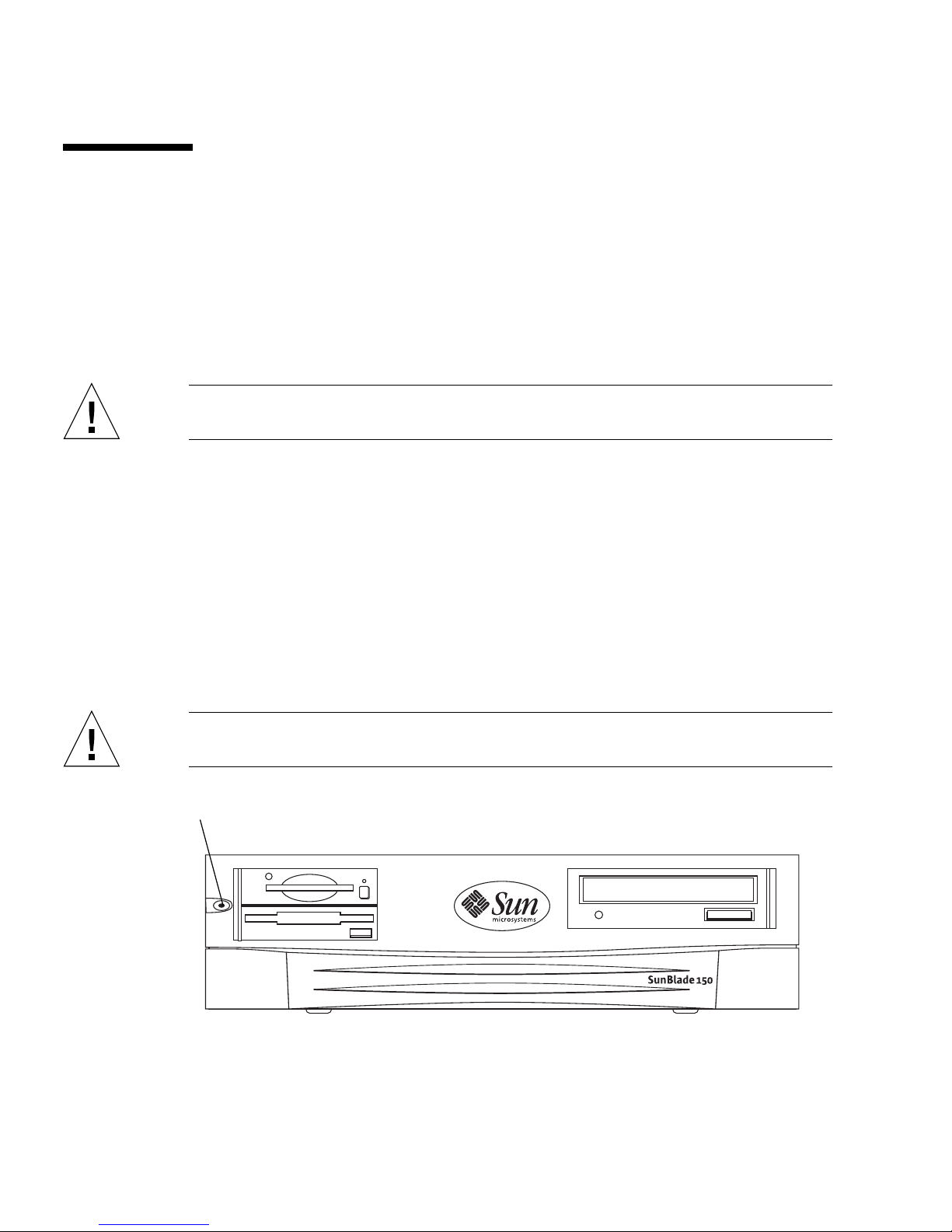
Momentarily press and release the front panel power switch (
automatically shut down all programs, the operating system, and to power off the
system.
From the system shutdown menu displayed on the monitor, select “Shutdown.”
■ If Solaris is not running in a windowing environment:
Press and hold the front panel power switch (
off the system.
FIGURE 1) for four seconds to power
FIGURE 1)to
Caution – This action forces an immediate power off of the system and unsaved
data is lost.
Power switch
FIGURE 1 Front Panel Power Switch
2 Sun Blade 150 CD-ROM, DVD-ROM, and Hard Drive Installation Guide • June 2002
Page 7

2. Verify the following:
■ The front panel power-indicator LED is off.
■ The system fans are not spinning.
3. Turn off the power to the monitor and any peripheral equipment.
4. Disconnect cables to any peripheral equipment.
Caution – Pressing the power switch does not remove all power from the system; a
trickle current remains in the power supply. To remove all power from the system,
disconnect the power cord.
Removing the System Cover
1. Using a No. 2 Phillips screwdriver, remove the two screws securing the system
cover to the chassis (
2. Slide the system cover toward the rear of the system until the cover tabs release.
3. Lift the system cover straight up and set the cover aside in a safe place.
FIGURE 2).
Sun Blade 150 CD-ROM, DVD-ROM, and Hard Drive Installation 3
Page 8
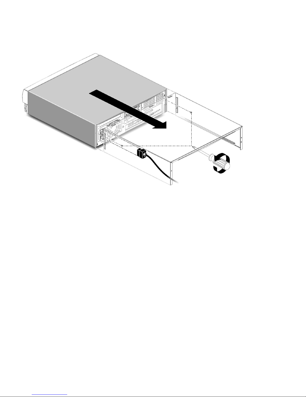
FIGURE 2 Removing the System Cover
Attaching the Antistatic Wrist Strap
1. Unwrap the first two folds of the wrist strap. Wrap the adhesive side firmly
against your wrist.
2. Peel the liner from the copper foil at the opposite end of the wrist strap.
3. Attach the copper end of the wrist strap to the chassis (
4. Disconnect the AC power cord from the system.
4 Sun Blade 150 CD-ROM, DVD-ROM, and Hard Drive Installation Guide • June 2002
FIGURE 3).
Page 9
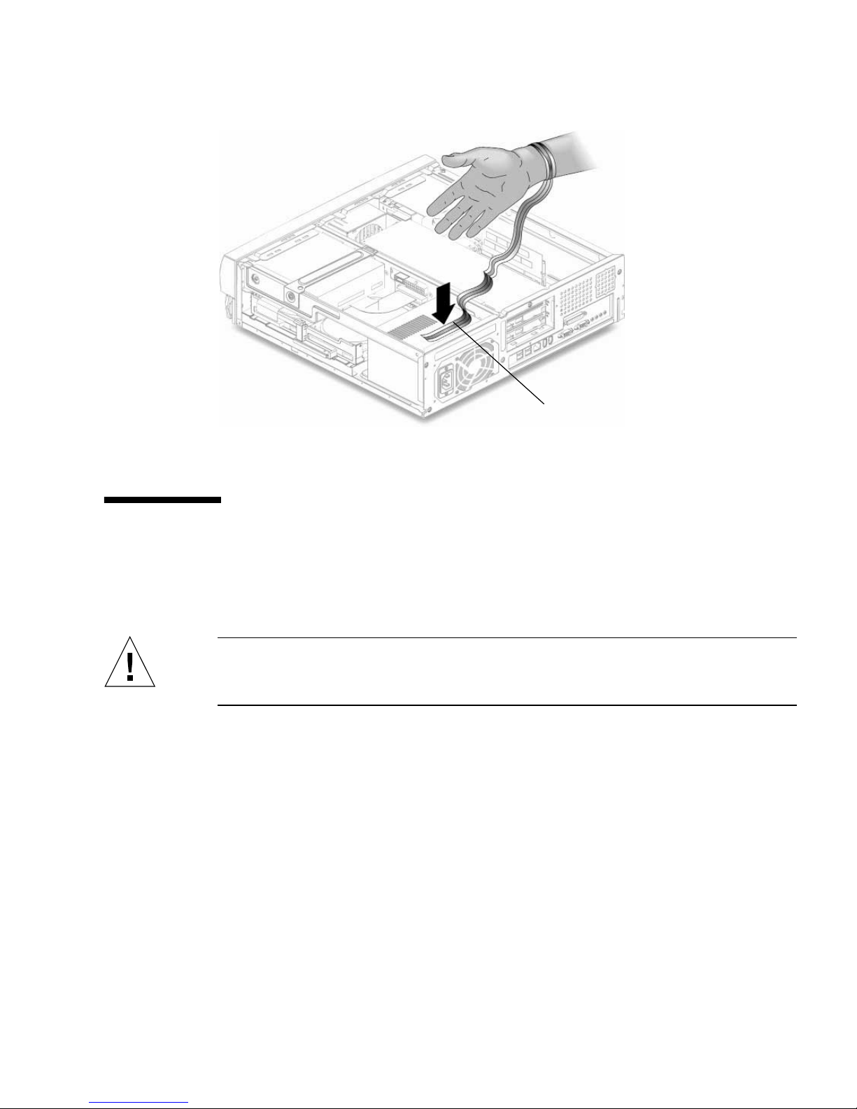
Copper end
FIGURE 3 Attaching the Wrist Strap to the Chassis
Removing a Primary Hard Drive
1. Power off the system, remove the system cover, and attach an antistatic wrist strap
as described in “Preparing to Replace Components” on page 2.
Caution – Use proper ESD grounding techniques when handling components. Wear
an antistatic wrist strap and use an antistatic mat. Store ESD-sensitive components in
antistatic bags before placing them on any surface.
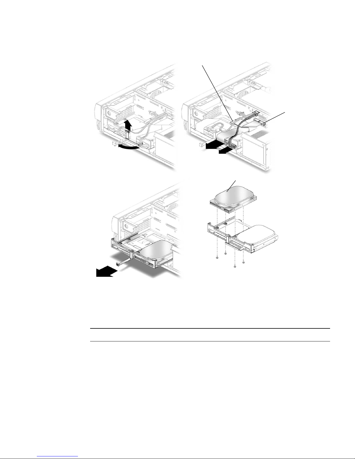
2. Lift the spring-loaded latch upward to release the hard drive tray from the chassis
FIGURE 4).
(
3. Pull the hard drive tray ejection lever away from the chassis.
4. Disconnect the hard drive IDE cable and the power cable connectors from both
hard drives (if two drives are installed).
Move the cables out of the way.
5. Slide the hard drive tray out of the chassis.
6. Turn the hard drive tray over and place it on an antistatic mat.
7. Using a No. 2 Phillips screwdriver, remove the four screws securing the hard drive
to the hard drive tray.
Sun Blade 150 CD-ROM, DVD-ROM, and Hard Drive Installation 5
Page 10
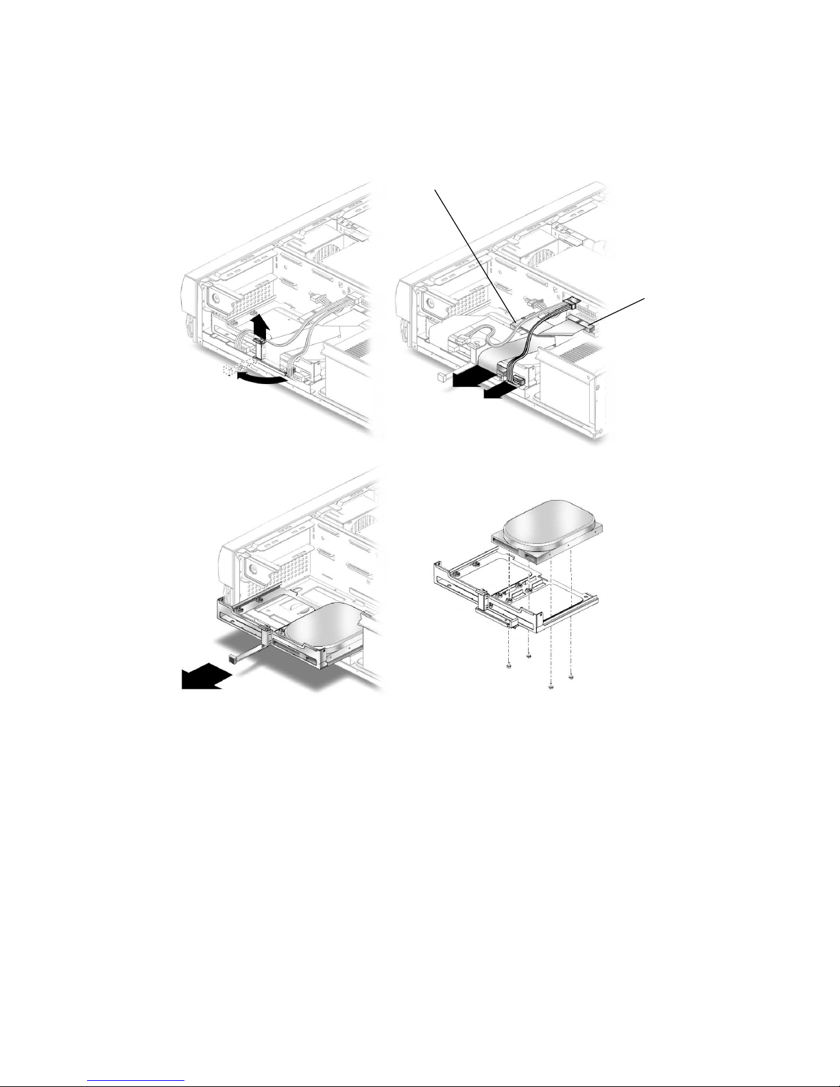
8. Lift the hard drive tray from the hard drive.
CD/DVD-ROM drive
IDE cable connector
IDE 1 (J504)
1
3
FIGURE 4 Removing and Replacing a Primary Hard Drive
2
4
6 Sun Blade 150 CD-ROM, DVD-ROM, and Hard Drive Installation Guide • June 2002
Page 11

Replacing a Primary Hard Drive
Note – Read the hard drive product guide for information about jumpers, switch
settings, or other installation tasks.
Note – Before you replace any hard drive, verify that the hard drive mode-select
jumper is set to “CS,” “Enable Cable Select,” or “Cable Select.”
1. Position the hard drive into the hard drive tray (
2. Turn the tray upside down on an antistatic mat.
3. Using a No. 2 Phillips screwdriver, replace the four screws securing the hard drive
to the hard drive tray.
4. Position the hard drive tray into the chassis.
5. While ensuring that the cables are not damaged, slide the hard drive tray into the
chassis until the spring-loaded latch clicks into place.
6. Connect the hard drive IDE cable connector labeled “Primary HDD” to the
primary hard drive.
FIGURE 4).
Note – Ensure that the cables are properly oriented by aligning the connector keys.
7. Connect the power cable to the hard drive.
Caution – Ensure that the cables will not be damaged when you replace the system
cover.
8. Detach the wrist strap, replace the system cover, and power on the system as
described in “Finishing Component Replacement” on page 13.
Sun Blade 150 CD-ROM, DVD-ROM, and Hard Drive Installation 7
Page 12

Installing a Secondary Hard Drive
The optional secondary hard drive mounts next to the primary hard drive on the
hard drive tray (
secondary hard drive. Use the following procedure to install the optional secondary
hard drive.
1. Power off the system, remove the system cover, and attach an antistatic wrist strap
as described in “Preparing to Replace Components” on page 2.
Caution – Use proper ESD grounding techniques when handling components. Wear
an antistatic wrist strap and use an antistatic mat. Store ESD-sensitive components in
antistatic bags before placing them on any surface.
2. Lift the spring-loaded latch upward to release the hard drive tray from the chassis
FIGURE 5).
(
3. Pull the hard drive tray ejection lever away from the chassis.
4. Disconnect the existing hard drive IDE and power cables from the primary hard
drive.
5. Slide the hard drive tray out of the chassis.
FIGURE 5). The secondary IDE cable assembly is used with the
6. Place the new secondary hard drive onto the hard drive tray.
7. Turn the tray upside down on an antistatic mat.
Note – Before installing the hard drive into the system, verify that the drive’s back-
panel mode-select jumper is set to “CS,” “Enable Cable Select,” or “Cable Select.”
8. Using a No. 2 Phillips screwdriver, install the four screws that secure the drive to
the hard drive tray.
9. While ensuring that the cables are not damaged, slide the hard drive tray into the
chassis until the spring-loaded latch clicks into place.
8 Sun Blade 150 CD-ROM, DVD-ROM, and Hard Drive Installation Guide • June 2002
Page 13
CD/DVD-ROM drive
IDE cable connector
1
2
IDE 1 (J504)
3
4
Secondary hard drive
FIGURE 5 Installing a Secondary Hard Drive
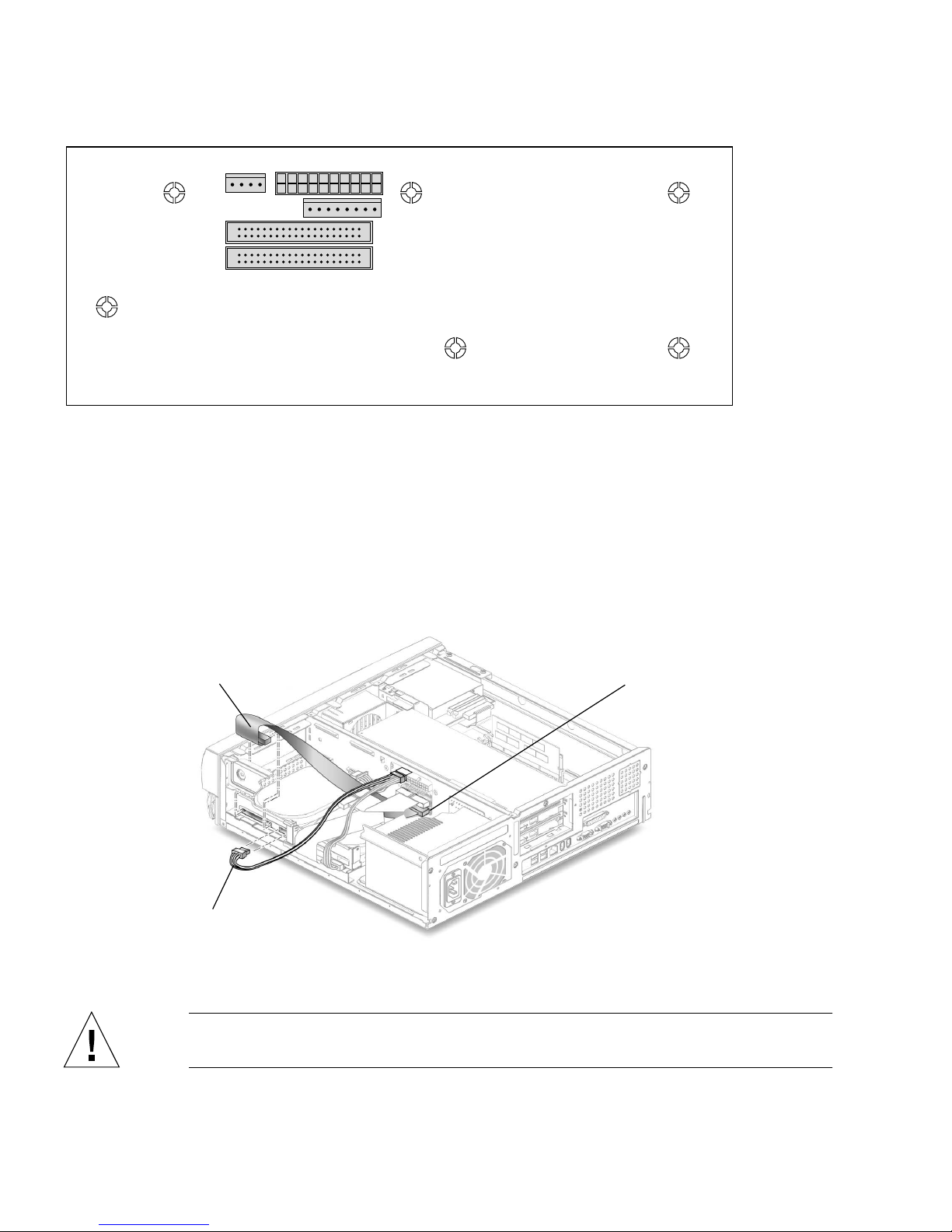
10. Verify that the secondary IDE cable connector is connected to riser board
connector IDE2 (J503). See
Note – Ensure that the cables are properly oriented by aligning the connector keys.
11. Verify that the CD-ROM or DVD-ROM cable is connected to the primary (IDE1,
J504) cable connector labeled CD/DVD (
12. Connect the hard drive IDE cable connector labeled “Primary HDD” to the
primary hard drive.
FIGURE 7.
FIGURE 5 and FIGURE 6).
Sun Blade 150 CD-ROM, DVD-ROM, and Hard Drive Installation 9
Page 14
J502
J501
J504
J503
FIGURE 6 Riser Board, Side Two
13. Connect the power cable to the secondary hard drive (FIGURE 7).
14. Connect the power cable to the primary hard drive.
15. Connect the secondary hard drive to the cable connector labeled “Secondary
HDD”.
The following diagram shows the cabling for the secondary hard drive.
Secondary HDD
IDE 1
IDE 2
IDE2 (J503)
Power cable
FIGURE 7 Secondary Hard Drive Cabling Configuration
Caution – Ensure that the cables will not be damaged when you replace the system
cover.
10 Sun Blade 150 CD-ROM, DVD-ROM, and Hard Drive Installation Guide • June 2002
Page 15

16. Detach the wrist strap, replace the system cover, and power on the system as
described in “Finishing Component Replacement” on page 13.
Removing a CD-ROM or DVD-ROM
Drive
1. Remove any CD or DVD media from the drive.
2. Power off the system, remove the system cover, and attach an antistatic wrist strap
as described in “Preparing to Replace Components” on page 2.
Caution – Use proper ESD grounding techniques when handling components. Wear
an antistatic wrist strap and use an antistatic mat. Store ESD-sensitive components in
antistatic bags before placing them on any surface.
3. Remove the following from the back of the CD-ROM or DVD-ROM drive
FIGURE 8):
(
■ CD-ROM or DVD-ROM drive IDE cable connector
■ Power cable connector
4. Using a No. 2 Phillips screwdriver, remove the two screws securing the CD-ROM
or DVD-ROM drive to the chassis.
5. Place your fingers on the back of the CD-ROM or DVD-ROM drive. Push the CDROM or DVD-ROM drive toward the chassis front and remove it.
6. Place the CD-ROM or DVD-ROM drive on an antistatic mat.
Sun Blade 150 CD-ROM, DVD-ROM, and Hard Drive Installation 11
Page 16
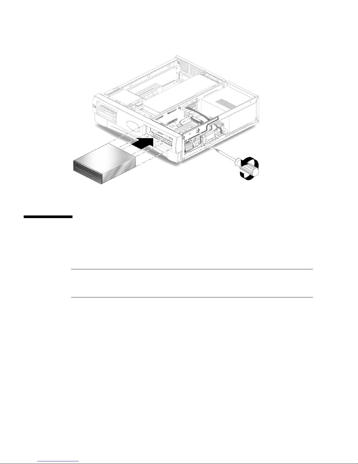
FIGURE 8 Removing and Replacing a CD-ROM or DVD-ROM Drive
Replacing a CD-ROM or DVD-ROM
Drive
Note – Before you replace the CD-ROM or DVD-ROM drive, verify that the
CD-ROM drive jumper (located on the CD-ROM drive back panel) is set to either
“CS,” “Cable Select” or “Enable Cable Select.”
1. Position the CD-ROM or DVD-ROM drive in the chassis (
2. Push the CD-ROM or DVD-ROM drive toward the chassis rear.
3. Connect the following to the rear of the CD-ROM or DVD-ROM drive:
■ CD-ROM or DVD-ROM drive cable connector
■ Power cable connector
4. Ensure that the cable assembly connectors are properly oriented by aligning the
connector keys.
5. Using a No. 2 Phillips screwdriver, replace the two screws securing the CD-ROM
or DVD-ROM drive to the chassis.
12 Sun Blade 150 CD-ROM, DVD-ROM, and Hard Drive Installation Guide • June 2002
FIGURE 8).
Page 17
6. Detach the wrist strap, replace the system cover, and power on the system as
described in “Finishing Component Replacement” on page 13.
Finishing Component Replacement
1. Remove the wrist strap from the system chassis and from your wrist.
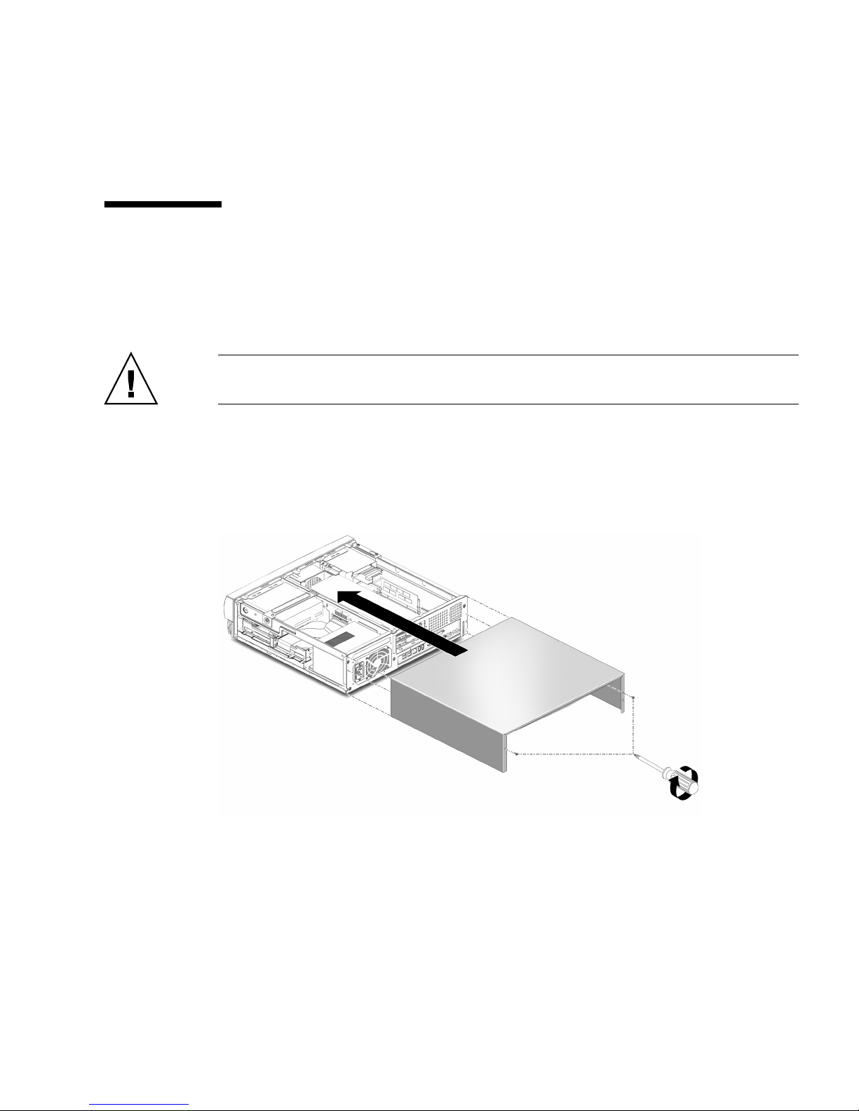
2. Position the system cover onto the system chassis.
Caution – Ensure that the hard drive cables will not be damaged when you replace
the system cover.
3. Slide the system cover toward the front of the system until the cover tabs lock
FIGURE 9).
(
4. Using a No. 2 Phillips screwdriver, replace the two screws securing the system
cover to the chassis.
FIGURE 9 Replacing the System Cover
Sun Blade 150 CD-ROM, DVD-ROM, and Hard Drive Installation 13
Page 18
Powering On the System
1. Connect the system power cord to the system and to an AC power outlet.
2. Reconnect and turn on power to any peripherals (so that the system can recognize
the peripherals when it is powered on).
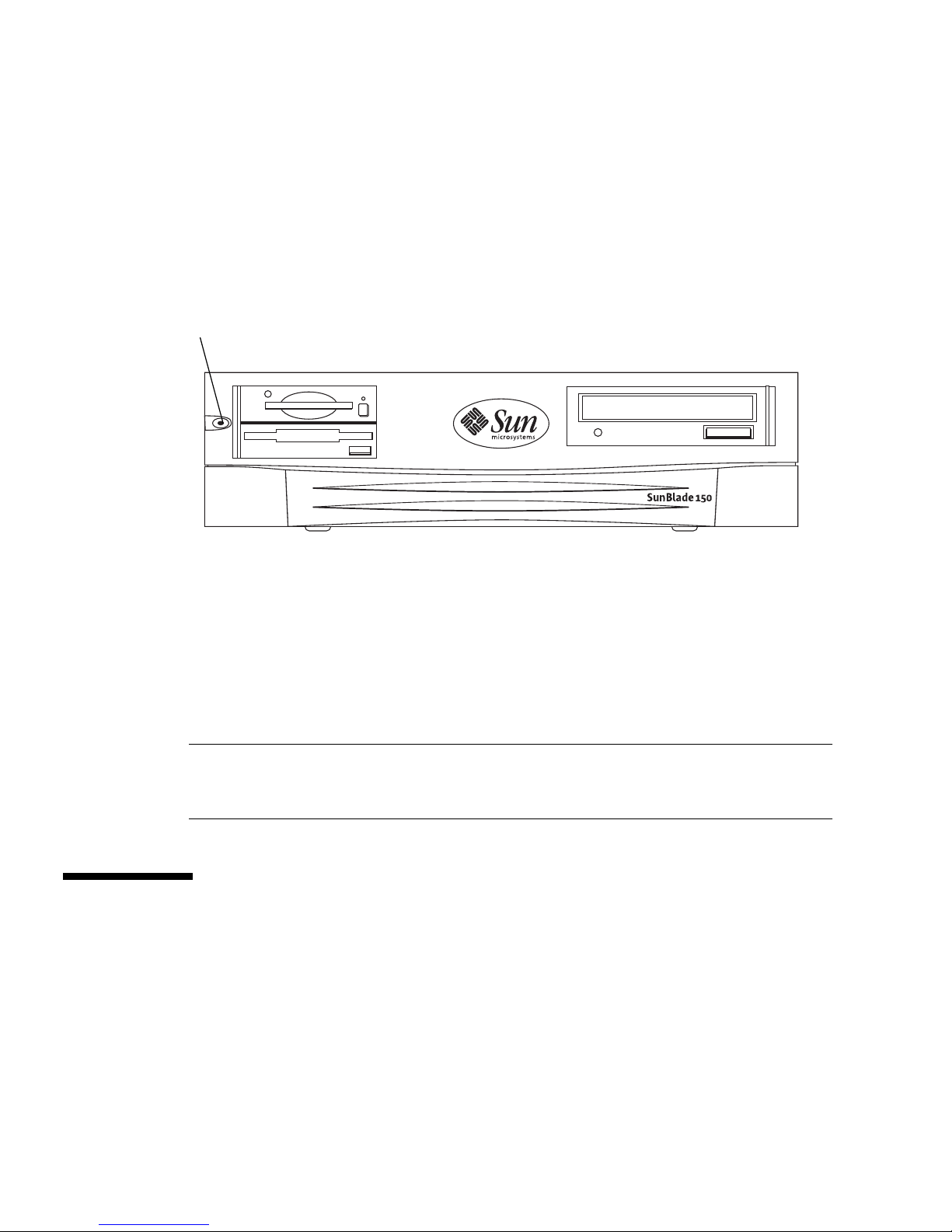
3. Press the front panel power switch (
Power switch
FIGURE 10 System Power Switch
FIGURE 10).
4. Verify the following:
■ The front panel power indicator LED is on.
■ The system fans are spinning.
If the system does not power on, see the “Troubleshooting” section in the Sun Blade
150 Getting Started Guide, 816-1161, or the Sun Blade 150 Service Manual, 816-4379.
Note – The Sun Blade 150 Getting Started Guide is translated into 10 languages. All 10
language versions are available on the CD-ROM that shipped with the Sun Blade 150
system.
Hard Drive Mirroring
This section describes the requirements and constraints of a hard drive mirroring
solution that uses Solstice DiskSuite
14 Sun Blade 150 CD-ROM, DVD-ROM, and Hard Drive Installation Guide • June 2002
TM
software.
Page 19
Hard Drive Mirroring Configuration
The IDE subsystem of the Sun Blade 150 system has two independent channels
designated “primary” and “secondary.” The system riser board has a connector for
each IDE Channel, labelled IDE1 (J504) and IDE 2 (J503).
Note – When mirroring hard drives in a Sun Blade 150 system, both hard drives
should be jumpered as “CS,” “Cable Select” or “Enable Cable Select” to allow for
automatic configuration.
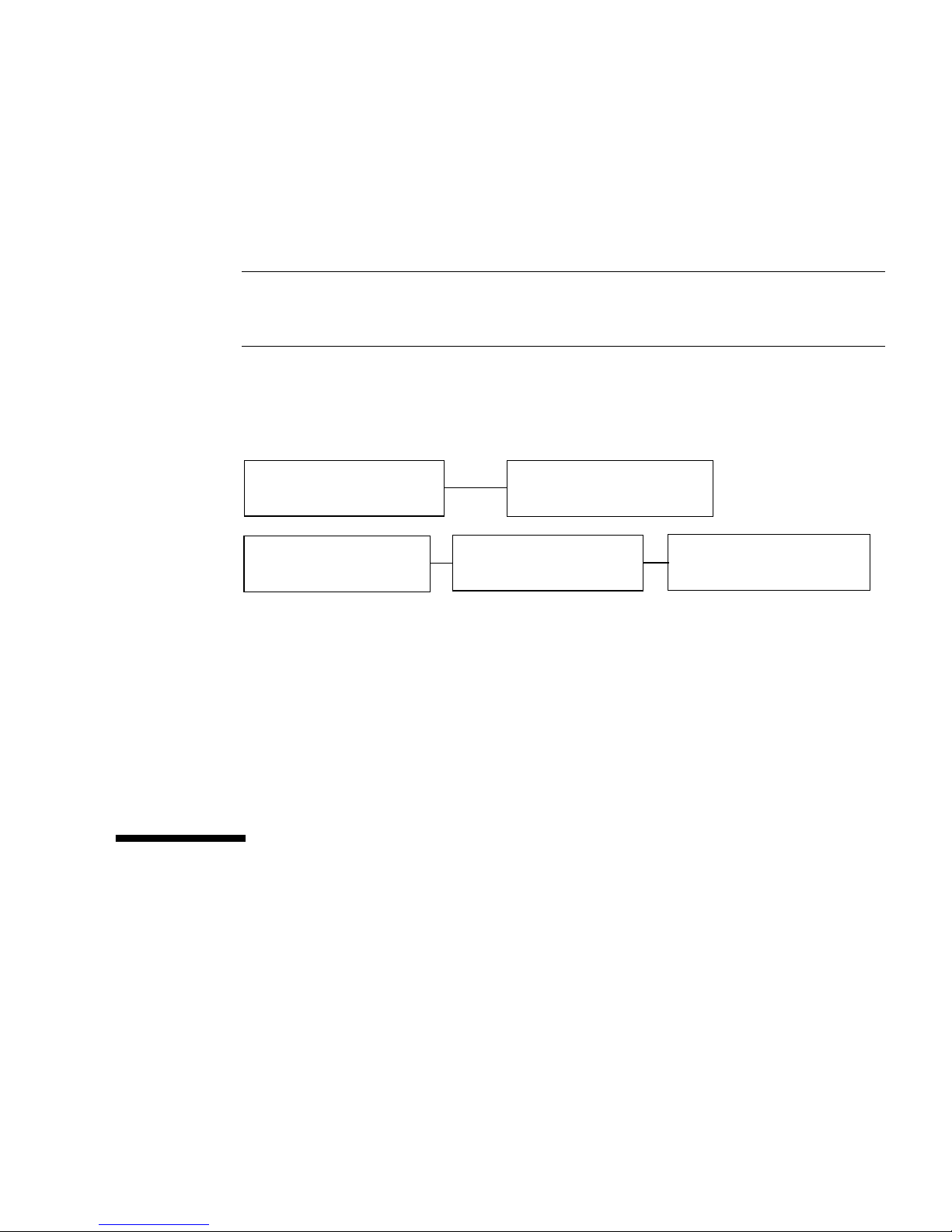
Two IDE cables are required for this configuration. Each cable is connected to the
riser board at one end and to a hard drive connector at the other end.
shows this hardware configuration (with an optional CD-ROM or DVD-ROM drive).
FIGURE 11
Riser board (J503)
IDE 2
Riser board (J504)
IDE 1
FIGURE 11 Hard Drive Mirroring Configuration
CD-ROM or DVD-ROM drive
Optional second hard drive
(Secondary HDD)
(CD/DVD)
Primary hard drive
(Primary HDD)
Required Software and Patches
The supported software is Solstice DiskSuite 4.2.1 or a subsequent compatible
release. For detailed instructions on configuring hard drives refer to see the Solstice
DiskSuite User’s Guide, part number 806-3205 at this web site:
http://docs.sun.com
CD or DVD Handling and Use
Inserting a CD or DVD Into the Drive
1. After the system is powered on, push the eject button on the CD-ROM or
DVD-ROM drive to open the drive tray.
Sun Blade 150 CD-ROM, DVD-ROM, and Hard Drive Installation 15
Page 20

2. Place the CD (label side up) into the tray.
Ensure that the CD is properly set into the recessed area of the tray.
3. Push the tray to close it.
Ejecting a CD or DVD
You may need to unmount the CD before manually ejecting it.
There are three ways to eject a CD:
■ Press the eject button on the front of the CD-ROM drive.
■ Use software commands to eject the CD. Refer to the peripherals handbook that
corresponds with your operating system.
■ If the motorized eject mechanism does not operate, insert a thin, stiff wire (such
as a paper clip) into the hole next to the eject button.
Cleaning a CD or DVD
!
If your CD-ROM drive cannot read a CD or DVD, the cause may be a dirty CD or
DVD. Follow these guidelines to clean a CD or DVD:
■ Use a soft, clean, lint-free, dry cloth.
■ Clean the unlabeled side of the CD or DVD.
■ Wipe the CD radially from the center to the outside.
■ Use professional cleaning kits.
Caution – Do not use solvents such as benzine, paint thinner, antistatic aerosol
spray, or abrasive cleaners to clean CDs.
Handling and Storing CDs and DVDs
Follow these guidelines when handling and storing CDs:
■ Handle CDs only by their edges; avoid touching CD or DVD surfaces.
■ Write only on the premarked label side of a CD or DVD. Use a soft felt-tip marker.
■ Do not use CDs in high-dust environments.
■ Keep CDs out of direct sunlight, extreme sources of heat or cold, and away from
dust and moisture.
■ Make sure CDs are at room temperature before using them.
■ Store CDs in storage boxes so that they remain clean and free of dust.
16 Sun Blade 150 CD-ROM, DVD-ROM, and Hard Drive Installation Guide • June 2002
 Loading...