

Page 1

Sun StorEdge 2G FC PCI Single
Channel Network Adapter
Installation Guide
Sun Microsystems, Inc.
4150 Network Circle
Santa Clara, CA 95054 U.S.A.
650-960-1300
Part No. 816-4999-10
May 2002, Revision A
Send comments about this document to: [email protected]
Page 2

Copyright 2002Sun Microsystems, Inc.,901 SanAntonio Road• PaloAlto, CA94303-4900 USA.All rightsreserved.
This product ordocument isprotected bycopyright anddistributed underlicenses restrictingits use,copying, distribution,and decompilation.
No part of this productor documentmay bereproduced inany formby anymeans withoutprior writtenauthorization ofSun andits licensors,
if any.Third-party software,including font technology,is copyrightedand licensedfrom Sunsuppliers.
Parts of the product maybe derivedfrom BerkeleyBSD systems,licensed fromthe Universityof California.UNIX isa registeredtrademark in
the U.S. and other countries, exclusively licensed through X/OpenCompany,Ltd. ForNetscape Communicator™,the followingnotice applies:
Copyright 1995 Netscape Communications Corporation. All rights reserved.
Sun, Sun Microsystems,the Sunlogo, AnswerBook2,docs.sun.com, SunEnterprise, SunVTS,StorEdge, andSolaris aretrademarks, registered
trademarks, or service marks of Sun Microsystems,Inc. inthe U.S.and othercountries. AllSPARCtrademarks areused underlicense andare
trademarks or registeredtrademarks ofSPARCInternational, Inc.in theU.S. andother countries.Products bearing SPARCtrademarks are
based upon an architecture developedby SunMicrosystems, Inc.
The OPEN LOOK and Sun™ Graphical User Interface was developed by Sun Microsystems,Inc. forits usersand licensees.Sun acknowledges
the pioneering effortsof Xeroxin researchingand developing the concept of visual or graphical user interfaces for the computer industry.Sun
holds a non-exclusive license fromXerox tothe XeroxGraphical UserInterface, whichlicense alsocovers Sun’slicensees whoimplement OPEN
LOOK GUIs and otherwise comply with Sun’s written license agreements.
RESTRICTEDRIGHTS: Use, duplication,or disclosure bythe U.S.Government issubject torestrictions ofFAR52.227-14(g)(2)(6/87) and
FAR52.227-19(6/87), or DFAR252.227-7015(b)(6/95) and DFAR227.7202-3(a).
DOCUMENTATION IS PROVIDED “AS IS” AND ALL EXPRESS OR IMPLIED CONDITIONS, REPRESENTATIONS AND WARRANTIES,
INCLUDING ANYIMPLIED WARRANTYOF MERCHANTABILITY,FITNESS FORA PARTICULARPURPOSE ORNON-INFRINGEMENT,
ARE DISCLAIMED, EXCEPT TO THE EXTENT THAT SUCH DISCLAIMERS ARE HELD TO BE LEGALLY INVALID.
Copyright 2002 Sun Microsystems, Inc.,901 SanAntonio Road• PaloAlto, CA94303-4900 Etats-Unis.Tousdroits réservés.
Ce produit oudocument estprotégé parun copyrightet distribuéavec deslicences quien restreignentl’utilisation, la copie, la distribution, et la
décompilation. Aucune partie de ce produit oudocument nepeut êtrereproduite sous aucune forme, par quelque moyen que ce soit, sans
l’autorisation préalable et écrite de Sun et de ses bailleurs de licence, s’il y en a. Le logiciel détenu par des tiers, et qui comprendla technologie
relativeaux policesde caractères,est protégépar uncopyright etlicencié pardes fournisseursde Sun.
Des parties de ce produitpourront êtredérivées dessystèmes BerkeleyBSD licenciéspar l’Universitéde Californie.UNIX estune marque
déposée aux Etats-Unis et dans d’autres payset licenciéeexclusivement parX/Open Company,Ltd. Lanotice suivanteest applicableà
Netscape Communicator™: Copyright 1995 Netscape Communications Corporation. Tousdroits réservés.
Sun, Sun Microsystems,the Sunlogo, AnswerBook2,docs.sun.com, SunEnterprise, SunVTS,StorEdge, etSolaris sontdes marquesde fabrique
ou des marquesdéposées, oumarques deservice, deSun Microsystems,Inc. auxEtats-Unis etdans d’autrespays. Toutesles marquesSPARC
sont utilisées sous licence et sont des marques defabrique oudes marquesdéposées deSPARCInternational, Inc.aux Etats-Uniset dans
d’autrespays. Lesproduits portantles marquesSPARCsont basés sur une architecturedéveloppée parSun Microsystems,Inc.
L’interfaced’utilisation graphique OPEN LOOK et Sun™ a été développée par Sun Microsystems, Inc.pour sesutilisateurs etlicenciés. Sun
reconnaîtles effortsde pionniersde Xeroxpour larechercheet ledéveloppement duconcept desinterfaces d’utilisationvisuelle ougraphique
pour l’industrie de l’informatique. Sun détient une licence non exclusive de Xerox surl’interface d’utilisationgraphique Xerox,cette licence
couvrant également les licenciés de Sun qui mettent en place l’interface d’utilisation graphique OPEN LOOK et qui en outrese conformentaux
licences écrites de Sun.
CETTE PUBLICATION EST FOURNIE "EN L’ETAT" ET AUCUNE GARANTIE, EXPRESSEOU IMPLICITE, N’ESTACCORDEE, Y COMPRIS
DES GARANTIESCONCERNANT LA VALEURMARCHANDE, L’APTITUDE DELA PUBLICATION AREPONDRE A UNEUTILISATION
PARTICULIERE, OU LE FAIT QU’ELLE NE SOIT PAS CONTREFAISANTE DE PRODUIT DE TIERS. CE DENI DE GARANTIE NE
S’APPLIQUERAIT PAS, DANS LA MESURE OU IL SERAIT TENU JURIDIQUEMENT NUL ET NON AVENU.
Please
Recycle
Page 3

Contents
1. Regulatory Compliance Statements 0–v
2. Safety Agency Compliance Statements 0–ix
Preface 3
Using UNIX Commands 3
Typographic Conventions 4
Shell Prompts 4
Related Documentation 5
Accessing Sun Documentation Online 5
Sun Welcomes Your Comments 5
3. Installation 1–1
1.1 Software Requirements 1–1
1.1.1 Device Drivers 1–1
1.2 Tools and Equipment Needed 1–2
1.3 Preparing for Installation 1–2
1.3.1 Sun Enterprise Systems 1–2
1.3.2 Preparing for a Sun StorEdge A5x00 Installation 1–3
1.4 Installing the Network Adapter 1–6
1.5 Testing the Installation 1–10
iii
Page 4

1.5.1 SunVTS 1–10
1.5.2 Testing Procedure 1–10
A. Specifications 5–1
A.1 PCI Card 5–1
A.2 Fibre Channel Interface Specifications 5–1
A.3 Performance Specifications 5–2
A.4 Power Requirements 5–3
A.5 Physical Dimensions 5–3
A.6 Regulatory Compliance 5–4
A.7 PCI-X Edge Connector Pin Definitions:
32-Bit Cards 5–5
A.8 PCI-X Edge Connector Pin Definitions:
64-Bit Cards 5–7
B. Booting From the Network Adapter 6–1
B.1 The Net Install Method 6–2
B.1.1 Overview For the Net Install Method 6–2
B.1.2 To Set Up the Boot/Install Server 6–3
B.1.3 To Modify the Boot Image 6–5
B.1.4 To Set Up the Client 6–6
B.2 The Dump and Restore Method 6–8
B.2.1 Overview Of the Dump and Restore Method 6–8
B.2.2 Partitioning the New Boot Disk the Same As the Temporary Boot
Disk 6–8
B.2.3 To Create File Systems on the New Boot Disk 6–18
B.2.4 To Create the New Boot Files 6–18
iv Sun StorEdge 2G FC PCI Single Channel Network Adapter Installation Guide • May 2002
Page 5

Regulatory Compliance Statements
Your Sun product is marked to indicate its compliance class:
• Federal Communications Commission (FCC) — USA
• Industry Canada Equipment Standard for Digital Equipment (ICES-003) - Canada
• Voluntary Control Council for Interference (VCCI) — Japan
• Bureau of Standards Metrology and Inspection (BSMI) — Taiwan
Please read the appropriate section that corresponds to the marking on your Sun product before attempting to install the
product.
FCC Class A Notice
This device complies with Part 15 of the FCC Rules. Operation is subject to the following two conditions:
1. This device may not cause harmful interference.
2. This device must accept any interference received, including interference that may cause undesired operation.
Note: This equipment has been tested and found to comply with the limits for a Class A digital device, pursuant to Part 15 of
the FCC Rules. These limits are designed to provide reasonable protection against harmful interference when the equipment
is operated in a commercial environment. This equipment generates, uses, and can radiate radio frequency energy, and if it is
not installed andused in accordance with theinstruction manual, it may causeharmful interference to radio communications.
Operation of thisequipment in a residentialarea is likelyto cause harmful interference,inwhich case the user willbe required
to correct the interference at his own expense.
Shielded Cables:Connections between theworkstationand peripherals mustbe made usingshielded cables tocomply with
FCC radio frequency emission limits. Networking connections can be made using unshielded twisted-pair (UTP) cables.
Modifications: Any modifications made to this device that are not approved by Sun Microsystems, Inc. may void the
authority granted to the user by the FCC to operate this equipment.
FCC Class B Notice
This device complies with Part 15 of the FCC Rules. Operation is subject to the following two conditions:
1. This device may not cause harmful interference.
2. This device must accept any interference received, including interference that may cause undesired operation.
Note: This equipment has been tested and found to comply with the limits for a Class B digital device, pursuant to Part 15 of
the FCC Rules. These limits are designed to provide reasonable protection against harmful interference in a residential
installation. This equipment generates, uses and can radiate radio frequency energy and, if not installed and used in
accordance with the instructions, may cause harmful interference to radio communications. However, there is no guarantee
that interference will not occur in a particular installation. If this equipment does cause harmful interference to radio or
television reception,which can be determined byturning the equipment offand on, the user isencouraged to try to correctthe
interference by one or more of the following measures:
• Reorient or relocate the receiving antenna.
• Increase the separation between the equipment and receiver.
• Connect the equipment into an outlet on a circuit different from that to which the receiver is connected.
• Consult the dealer or an experienced radio/television technician for help.
Shielded Cables: Connections between the workstation and peripherals must be made using shielded cables in order to
maintain compliance with FCC radio frequency emission limits. Networking connections can be made using unshielded
twisted pair (UTP) cables.
Modifications: Any modifications made to this device that are not approved by Sun Microsystems, Inc. may void the
authority granted to the user by the FCC to operate this equipment.
v
Page 6
ICES-003 Class A Notice - AvisNMB-003, Classe A
This Class A digital apparatus complies with Canadian ICES-003.
Cet appareil numérique de la classe A est conforme à la norme NMB-003 du Canada.
ICES-003 Class B Notice - AvisNMB-003, Classe B
This Class B digital apparatus complies with Canadian ICES-003.
Cet appareil numérique de la classe B est conforme à la norme NMB-003 du Canada.
vi Sun StorEdge 2G FC PCI Single Channel Network Adapter Installation Guide • May 2002
Page 7

This page is intentionally left blank.
vii
Page 8

This page is intentionally left blank.
viii Sun StorEdge 2G FC PCI Single Channel Network Adapter Installation Guide • May 2002
Page 9
Safety Agency Compliance
Statements
Read this section before beginning any procedure. The
following text provides safety precautions to follow when
installing a Sun Microsystems product.
Safety Precautions
For your protection, observe the following safety
precautions when setting up your equipment:
■ Follow all cautions and instructions marked on the
equipment.
■ Ensure that the voltage and frequency of your power
source match the voltage and frequency inscribed on
the equipment’s electrical rating label.
■ Never push objects of any kind through openings in
the equipment. Dangerous voltages may be present.
Conductive foreign objects could produce a short
circuit that could cause fire, electric shock, or damage
to your equipment.
Symbols
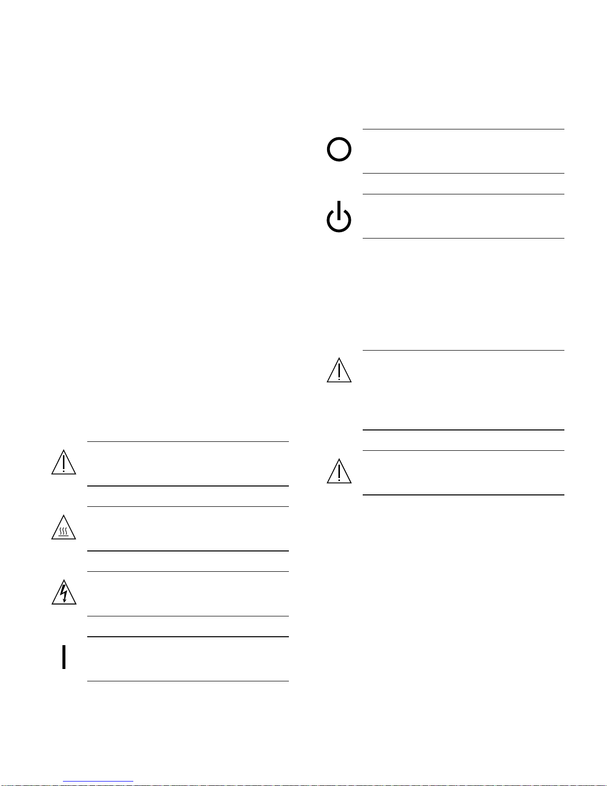
The following symbols may appear in this book:
Dependingonthetypeofpowerswitchyourdevicehas,
one of the following symbols may be used:
Off - Removes AC power from the system.
Standby – The On/Standby switch is in the
standby position.
Modifications to Equipment
Do not make mechanical or electrical modifications to the
equipment. Sun Microsystems is not responsible for
regulatory compliance of a modified Sun product.
Placement of a Sun Product
Caution – Do not block or cover the openings
of your Sun product. Never place a Sun
product near a radiator or heat register.
Failure to follow these guidelines can cause
overheating and affect the reliability of your
Sun product.
Caution – There is risk of personal injury and
equipment damage. Follow the instructions.
Caution – Hot surface. Avoid contact. Surfaces
are hot and may cause personal injury if
touched.
Caution – Hazardous voltages are present. To
reduce the risk of electric shock and danger to
personal health, follow the instructions.
On – Applies AC power to the system.
Caution – The workplace-dependent noise
level defined in DIN 45 635 Part 1000 must be
70Db(A) or less.
SELV Compliance
Safety status of I/O connections comply to SELV
requirements.
ix
Page 10
Power Cord Connection
Lithium Battery
Caution – Sun products are designed to work
with single-phase power systems having a
grounded neutral conductor. To reduce the
risk of electric shock, do not plug Sun
products into any other type of power system.
Contact your facilities manager or a qualified
electrician if you are not sure what type of
power is supplied to your building.
Caution – Not all power cords have the same
current ratings. Household extension cords do
not have overload protection and are not
meant for use with computer systems. Do not
use household extension cords with your Sun
product.
Caution – Your Sun product is shipped with a
grounding type (three-wire) power cord. To
reduce the risk of electric shock, always plug
the cord into a grounded power outlet.
The following caution applies only to devices with a
Standby power switch:
Caution – On Sun CPU boards, there is a
lithium battery molded into the real-time
clock, SGS No. MK48T59Y, MK48TXXB-XX,
MK48T18-XXXPCZ, M48T59W-XXXPCZ, or
MK48T08. Batteries are not customer
replaceable parts. They may explode if
mishandled. Do not dispose of the battery in
fire. Do not disassemble it or attempt to
recharge it.
Battery Pack
Caution – There is a sealed lead acid battery
in Sun StorEdge 2G FC PCI Single Channel
Network Adapter Installation Guide units.
Portable Energy Products No. TLC02V50.
There is danger of explosion if the battery
pack is mishandled or incorrectly replaced.
Replace only with the same type of Sun
Microsystems battery pack. Do not
disassemble it or attempt to recharge it
outside the system. Do not dispose of the
battery in fire. Dispose of the battery properly
in accordance with local regulations.
Caution – The power switch of this product
functions as a standby type device only. The
power cord serves as the primary disconnect
device for the system. Be sure to plug the
power cord into a grounded power outlet that
is nearby the system and is readily accessible.
Do not connect the power cord when the
power supply has been removed from the
system chassis.
System Unit Cover
You must remove the cover of your Sun computer system
unit to add cards, memory, or internal storage devices. Be
sure to replace the top cover before powering on your
computer system.
Caution – Do not operate Sun products
without the top cover in place. Failure to take
this precaution may result in personal injury
and system damage.
Laser Compliance Notice
Sun products that use laser technology comply with Class 1
laser requirements.
x Sun StorEdge 2G FC PCI Single Channel Network Adapter Installation Guide • May 2002
Page 11
CD-ROM
Class 1 Laser Product
Luokan 1 Laserlaite
Klasse 1 Laser Apparat
Laser KLasse 1
Achtung – Gefahr von Verletzung und
Geräteschaden. Befolgen Sie die
Anweisungen.
Achtung – Hohe Temperatur. Nicht berühren,
da Verletzungsgefahr durch heiße Oberfläche
besteht.
Caution – Use of controls, adjustments, or the
performance of procedures other than those
specified herein may result in hazardous
radiation exposure.
Einhaltung sicherheitsbehördlicher
Vorschriften
Auf dieser Seite werden Sicherheitsrichtlinien beschrieben,
die bei der Installation von Sun-Produkten zu beachten
sind.
Sicherheitsvorkehrungen
Treffen Sie zu Ihrem eigenen Schutz die folgenden
Sicherheitsvorkehrungen, wenn Sie Ihr Gerät installieren:
■ Beachten Sie alle auf den Geräten angebrachten
Warnhinweise und Anweisungen.
■ Vergewissern Sie sich, daß Spannung und Frequenz
Ihrer Stromquelle mit der Spannung und Frequenz
übereinstimmen, die auf dem Etikett mit den
elektrischen Nennwerten des Geräts angegeben sind.
■ Stecken Sie auf keinen Fall irgendwelche Gegenstände
in Öffnungen in den Geräten. Leitfähige Gegenstände
könnten aufgrund der möglicherweise vorliegenden
gefährlichen Spannungen einen Kurzschluß
verursachen, der einen Brand, Stromschlag oder
Geräteschaden herbeiführen kann.
Achtung – Gefährliche Spannungen.
Anweisungen befolgen, um Stromschläge und
Verletzungen zu vermeiden.
Ein – Setzt das System unter Wechselstrom.
Je nach Netzschaltertyp an Ihrem Gerät kann eines der
folgenden Symbole benutzt werden:
Aus – Unterbricht die Wechselstromzufuhr
zum Gerät.
Wartezustand (Stand-by-Position) - Der Ein-/
Wartezustand-Schalter steht auf
Wartezustand. Änderungen an Sun-Geräten.
Nehmen Sie keine mechanischen oder elektrischen
Änderungen an den Geräten vor. Sun Microsystems,
übernimmt bei einem Sun-Produkt, das geändert wurde,
keine Verantwortung für die Einhaltung behördlicher
Vorschriften
Symbole
Die Symbole in diesem Handbuch haben folgende
Bedeutung:
xi
Page 12
Aufstellung von Sun-Geräten
Achtung – Um den zuverlässigen Betrieb
Ihres Sun-Geräts zu gewährleisten und es vor
Überhitzung zu schützen, dürfen die
Öffnungen im Gerät nicht blockiert oder
verdeckt werden. Sun-Produkte sollten
niemals in der Nähe von Heizkörpern oder
Heizluftklappen aufgestellt werden.
Achtung – Der arbeitsplatzbezogene
Schalldruckpegel nach DIN 45 635 Teil 1000
beträgt 70Db(A) oder weniger.
Einhaltung der SELV-Richtlinien
Die Sicherung der I/O-Verbindungen entspricht den
Anforderungen der SELV-Spezifikation.
Anschluß des Netzkabels
Achtung – Sun-Produkte sind für den Betrieb
an Einphasen-Stromnetzen mit geerdetem
Nulleiter vorgesehen. Um die
Stromschlaggefahr zu reduzieren, schließen
Sie Sun-Produkte nicht an andere
Stromquellen an. Ihr Betriebsleiter oder ein
qualifizierter Elektriker kann Ihnen die Daten
zur Stromversorgung in Ihrem Gebäude
geben.
Achtung – Nicht alle Netzkabel haben die
gleichen Nennwerte. Herkömmliche, im
Haushalt verwendete Verlängerungskabel
besitzen keinen Überlastungsschutz und sind
daher für Computersysteme nicht geeignet.
Achtung – Ihr Sun-Gerät wird mit einem
dreiadrigen Netzkabel für geerdete
Netzsteckdosen geliefert. Um die Gefahr eines
Stromschlags zu reduzieren, schließen Sie das
Kabel nur an eine fachgerecht verlegte,
geerdete Steckdose an.
Die folgende Warnung gilt nur für Geräte mit
Wartezustand-Netzschalter:
Achtung – Der Ein/Aus-Schalter dieses
Geräts schaltet nur auf Wartezustand (StandBy-Modus). Um die Stromzufuhr zum Gerät
vollständig zu unterbrechen, müssen Sie das
Netzkabel von der Steckdose abziehen.
Schließen Sie den Stecker des Netzkabels an
eine in der Nähe befindliche, frei zugängliche,
geerdete Netzsteckdose an. Schließen Sie das
Netzkabel nicht an, wenn das Netzteil aus der
Systemeinheit entfernt wurde.
Lithiumbatterie
Achtung – CPU-Karten von Sun verfügen
über eine Echtzeituhr mit integrierter
Lithiumbatterie (Teile-Nr. MK48T59Y,
MK48TXXB-XX, MK48T18-XXXPCZ,
M48T59W-XXXPCZ, oder MK48T08). Diese
Batterie darf nur von einem qualifizierten
Servicetechniker ausgewechselt werden,dasie
bei falscher Handhabung explodieren kann.
Werfen Sie die Batterie nicht ins Feuer.
Versuchen Sie auf keinen Fall, die Batterie
auszubauen oder wiederaufzuladen.
Batterien
Achtung – Die Geräte Sun StorEdge 2G FC
PCI Single Channel Network Adapter
Installation Guide enthalten auslaufsichere
Bleiakkumulatoren. Produkt-Nr. TLC02V50
für portable Stromversorgung. Werden bei der
Behandlung oder beim Austausch der Batterie
Fehler gemacht, besteht Explosionsgefahr.
Batterie nur gegen Batterien gleichen Typs von
Sun Microsystems austauschen. Nicht
demontieren und nicht versuchen, die Batterie
außerhalb des Geräts zu laden. Batterie nicht
ins Feuer werfen. Ordnungsgemäß
entsprechend den vor Ort geltenden
Vorschriften entsorgen.
xii Sun StorEdge 2G FC PCI Single Channel Network Adapter Installation Guide • May 2002
Page 13
Gehäuseabdeckung
Sie müssen die obere Abdeckung Ihres Sun-Systems
entfernen, um interne Komponenten wie Karten,
Speicherchips oder Massenspeicher hinzuzufügen. Bringen
Sie die obere Gehäuseabdeckung wieder an, bevor Sie Ihr
System einschalten.
■ Ne jamais introduire d’objets quels qu’ils soient dans
une des ouvertures de l’appareil. Vous pourriez vous
trouver en présence de hautes tensions dangereuses.
Tout objet conducteur introduit de la sorte pourrait
produire un court-circuit qui entraînerait des
flammes, des risques d’électrocution ou des dégâts
matériels.
Achtung – Bei Betrieb des Systems ohne obere
Abdeckung besteht die Gefahr von
Stromschlag und Systemschäden.
Einhaltung der Richtlinien für Laser
Sun-Produkte, die mit Laser-Technologie arbeiten,
entsprechen den Anforderungen der Laser Klasse 1.
Class 1 Laser Product
Luokan 1 Laserlaite
Klasse 1 Laser Apparat
Laser KLasse 1
CD-ROM
Warnung – Die Verwendung von anderen
Steuerungen und Einstellungen oder die
Durchfhrung von Prozeduren, die von den
hier beschriebenen abweichen, knnen
gefhrliche Strahlungen zur Folge haben.
Symboles
Vous trouverez ci-dessous la signification des différents
symboles utilisés :
Attention: – risques de blessures corporelles
et de dégâts matériels. Veuillez suivre les
instructions.
Attention: – surface à température élevée.
Evitez le contact. La température des surfaces
est élevée et leur contact peut provoquer des
blessures corporelles.
Attention: – présence de tensions
dangereuses. Pour éviter les risques
d’électrocution et de danger pour la santé
physique, veuillez suivre les instructions.
MARCHE – Votre système est sous tension
(courant alternatif).
Conformité aux normes de sécurité
Ce texte traite des mesures de sécurité qu’il convient de
prendre pour l’installation d’un produit Sun Microsystems.
Mesures de sécurité
Pour votre protection, veuillez prendre les précautions
suivantes pendant l’installation du matériel :
■ Suivre tous les avertissements et toutes les
instructions inscrites sur le matériel.
■ Vérifier que la tension et la fréquence de la source
d’alimentation électrique correspondent à la tension et
à la fréquence indiquées sur l’étiquette de
classification de l’appareil.
Un des symboles suivants sera peut-être utilisé en fonction
du type d'interrupteur de votre système:
ARRET - Votre système est hors tension
(courant alternatif).
VEILLEUSE – L'interrupteur Marche/
Veilleuse est en position « Veilleuse ».
xiii
Page 14
Modification du matériel
Ne pas apporter de modification mécanique ou électrique
au matériel. Sun Microsystems n’est pas responsable de la
conformité réglementaire d’un produit Sun qui a été
modifié.
Positionnement d’un produit Sun
Attention: – pour assurer le bon
fonctionnement de votre produit Sun et pour
l’empêcher de surchauffer, il convient de ne
pas obstruer ni recouvrir les ouvertures
prévues dans l’appareil. Un produit Sun ne
doit jamais être placé à proximité d’un
radiateur ou d’une source de chaleur.
Attention: – Le niveau de pression acoustique
au poste de travail s'élève selon la norme DIN
45 635 section 1000, à 70 dB (A) ou moins.
Conformité SELV
Sécurité : les raccordements E/S sont conformes aux
normes SELV.
Connexion du cordon d’alimentation.
Attention: – tous les cordons d’alimentation
n’ont pas forcément la même puissance
nominale en matière de courant. Les rallonges
d’usage domestique n’offrent pas de
protection contre les surcharges et ne sont pas
prévues pour les systèmes d’ordinateurs. Ne
pas utiliser de rallonge d’usage domestique
avec votre produit Sun.
Attention: – votre produit Sun a été livré
équipé d’un cordon d’alimentation à trois fils
(avec prise de terre). Pour écarter tout risque
d’électrocution, branchez toujours ce cordon
dans une prise mise à la terre.
L'avertissement suivant s'applique uniquement aux
systèmes équipés d'un interrupteur VEILLEUSE:
Attention: – le commutateur d’alimentation
de ce produit fonctionne comme un dispositif
de mise en veille uniquement. C’est la prise
d’alimentation qui sert à mettre le produit
hors tension. Veillez donc à installer le produit
à proximité d’une prise murale facilement
accessible. Ne connectez pas la prise
d’alimentation lorsque le châssis du système
n’est plus alimenté.
Attention: – les produits Sun sont conçus
pour fonctionner avec des alimentations
monophasées munies d’un conducteur neutre
mis à la terre. Pour écarter les risques
d’électrocution, ne pas brancher de produit
Sun dans un autre type d’alimentation secteur.
En cas de doute quant au type d’alimentation
électrique du local, veuillez vous adresser au
directeur de l’exploitation ou à un électricien
qualifié.
xiv Sun StorEdge 2G FC PCI Single Channel Network Adapter Installation Guide • May 2002
Batterie au lithium
Attention: – sur les cartes CPU Sun, une
batterie au lithium (référence MK48T59Y,
MK48TXXB-XX, MK48T18-XXXPCZ,
M48T59W-XXXPCZ, ou MK48T08.) a été
moulée dans l’horloge temps réel SGS. Les
batteries ne sont pas des pièces remplaçables
par le client. Elles risquent d’exploser en cas
de mauvais traitement. Ne pas jeter la batterie
au feu. Ne pas la démonter ni tenter de la
recharger.
Page 15
Bloc-batterie
CD-ROM
Attention: – Les unités Sun StorEdge 2G FC
PCI Single Channel Network Adapter
Installation Guide contiennent une batterie
étanche au plomb (produits énergétiques
portatifs n˚TLC02V50). Il existe un risque
d’explosion si ce bloc-batterie est manipulé de
façon erronée ou mal mis en place. Ne
remplacez ce bloc que par un bloc-batterie Sun
Microsystems du même type. Ne le démontez
pas et n’essayez pas de le recharger hors du
système. Ne faites pas brûler la batterie mais
mettez-la au rebut conformément aux
réglementations locales en vigueur.
Couvercle
Pour ajouter des cartes, de la mémoire, ou des unités de
stockage internes, vous devrez démonter le couvercle de
l’unité systèmeSun. Ne pasoublier de remettre cecouvercle
en place avant de mettre le système sous tension.
Attention: – il est dangereux de faire
fonctionner un produit Sun sans le couvercle
en place. Si l’on néglige cette précaution, on
encourt des risques de blessures corporelles et
de dégâts matériels.
Attention: – L’utilisation de contrôles, de
réglages ou de performances de procédures
autre que celle spécifiée dans le présent
document peut provoquer une exposition à
des radiations dangereuses.
Normativas de seguridad
El siguiente texto incluye las medidas de seguridad que se
deben seguir cuando se instale algún producto de Sun
Microsystems.
Precauciones de seguridad
Para su protección observe las siguientes medidas de
seguridad cuando manipule su equipo:
■ Siga todas los avisos e instrucciones marcados en el
equipo.
■ Asegúrese de que el voltaje y la frecuencia de la red
eléctrica concuerdan con las descritas en las etiquetas
de especificaciones eléctricas del equipo.
■ No introduzca nunca objetos de ningún tipo a través
de los orificios del equipo. Pueden haber voltajes
peligrosos. Los objetos extraños conductores de la
electricidad pueden producir cortocircuitos que
provoquen un incendio, descargas eléctricas o daños
en el equipo.
Conformité aux certifications Laser
Les produitsSunqui font appel auxtechnologieslasers sont
conformes aux normes de la classe 1 en la matière.
Class 1 Laser Product
Luokan 1 Laserlaite
Klasse 1 Laser Apparat
Laser KLasse 1
Símbolos
En este libro aparecen los siguientes símbolos:
Precaución – Existe el riesgo de lesiones
personales y daños al equipo. Siga las
instrucciones.
Precaución – Superficie caliente. Evite el
contacto. Las superficies están calientes y
pueden causar daños personales si se tocan.
xv
Page 16
Precaución – Voltaje peligroso presente. Para
reducir el riesgo de descarga y daños para la
salud siga las instrucciones.
Encendido – Aplica la alimentación de CA al
sistema.
Según el tipo de interruptor de encendido que su equipo
tenga, es posible que se utilice uno de los siguientes
símbolos:
Apagado - Elimina la alimentación de CA del
sistema.
Cumplimiento de la normativa SELV
El estado de la seguridad de las conexiones de entrada/
salida cumple los requisitos de la normativa SELV.
Conexión del cable de alimentación eléctrica
Precaución – Los productos Sun están
diseñados para trabajar en una red eléctrica
monofásica con toma de tierra. Para reducir el
riesgo de descarga eléctrica, no conecte los
productos Sun a otro tipo de sistema de
alimentación eléctrica. Póngase en contacto
con el responsable de mantenimiento o con un
electricista cualificado si no está seguro del
sistema de alimentación eléctrica del que se
dispone en su edificio.
En espera – El interruptor de Encendido/En
espera se ha colocado en la posición de En
espera.
Modificaciones en el equipo
No realice modificaciones de tipo mecánico o eléctrico en el
equipo. Sun Microsystems no se hace responsable del
cumplimiento de las normativas de seguridad en los
equipos Sun modificados.
Ubicación de un producto Sun
Precaución – Para asegurar la fiabilidad de
funcionamiento de su producto Sun y para
protegerlo de sobrecalentamien-tos no deben
obstruirse o taparse las rejillas del equipo. Los
productos Sun nunca deben situarse cerca de
radiadores o de fuentes de calor.
Precaución – De acuerdo con la norma DIN 45
635, Parte 1000, se admite un nivel de presión
acústica para puestos de trabajo máximo de
70Db(A).
Precaución – No todos los cables de
alimentación eléctrica tienen la misma
capacidad. Los cables de tipo doméstico no
están provistos de protecciones contra
sobrecargas y por tanto no son apropiados
para su uso con computadores. No utilice
alargadores de tipo doméstico para conectar
sus productos Sun.
Precaución – Con el producto Sun se
proporciona un cable de alimentación con
toma de tierra. Para reducir el riesgo de
descargas eléctricas conéctelo siempre a un
enchufe con toma de tierra.
xvi Sun StorEdge 2G FC PCI Single Channel Network Adapter Installation Guide • May 2002
Page 17
La siguiente advertencia se aplica solamente a equipos con
un interruptor de encendido que tenga una posición "En
espera":
Precaución – El interruptor de encendido de
este producto funciona exclusivamente como
un dispositivo de puesta en espera. El enchufe
de la fuente de alimentación está diseñado
para ser el elemento primario de desconexión
del equipo. El equipo debe instalarse cerca del
enchufe de forma que este último pueda ser
fácil y rápidamente accesible. No conecte el
cable de alimentación cuando se ha retirado la
fuente de alimentación del chasis del sistema.
internos. Asegúrese de cerrar la tapa superior antes de
volver a encender el equipo.
Precaución – Es peligroso hacer funcionar los
productos Sun sin la tapa superior colocada.
El hecho de no tener en cuenta esta precaución
puede ocasionar daños personales o
perjudicar el funcionamiento del equipo.
Aviso de cumplimiento con requisitos de láser
Los productos Sun que utilizan la tecnología de láser
cumplen con los requisitos de láser de Clase 1.
Batería de litio
Precaución – En las placas de CPU Sun hay
una batería de litio insertada en el reloj de
tiempo real, tipo SGS Núm. MK48T59Y,
MK48TXXB-XX, MK48T18-XXXPCZ,
M48T59W-XXXPCZ, o MK48T08. Las baterías
no son elementos reemplazables por el propio
cliente. Pueden explotar si se manipulan de
forma errónea. No arroje las baterías al fuego.
No las abra o intente recargarlas.
Paquete de pilas
Precaución – Las unidades Sun StorEdge 2G
FC PCI Single Channel Network Adapter
Installation Guide contienen una pila de
plomo sellada, Productos de energía portátil
nº TLC02V50. Existe riesgo de estallido si el
paquete de pilas se maneja sin cuidado o se
sustituye de manera indebida. Las pilas sólo
deben sustituirse por el mismo tipo de
paquete de pilas de Sun Microsystems. No las
desmonte ni intente recargarlas fuera del
sistema. No arroje las pilas al fuego.
Deséchelas siguiendo el método indicado por
las disposiciones vigentes.
Class 1 Laser Product
Luokan 1 Laserlaite
Klasse 1 Laser Apparat
Laser KLasse 1
CD-ROM
Precaución – El manejo de los controles, los
ajustes o la ejecución de procedimientos
distintos a los aquí especificados pueden
exponer al usuario a radiaciones peligrosas.
GOST-R Certification Mark
Tapa de la unidad del sistema
Debe quitar la tapa del sistema cuando sea necesario añadir
tarjetas, memoria o dispositivos de almacenamiento
xvii
Page 18

This page is intentionally left blank.
Norge
ADVARSEL – Litiumbatteri —
Eksplosjonsfare.Ved utskifting benyttes kun
batteri som anbefalt av apparatfabrikanten.
Brukt batteri returneres apparatleverandøren.
Sverige
Danmark
Suomi
VARNING – Explosionsfara vid felaktigt
batteribyte. Använd samma batterityp eller
en ekvivalent typ som rekommenderas av
apparattillverkaren. Kassera använt batteri
enligt fabrikantens instruktion.
ADVARSEL! – Litiumbatteri —
Eksplosionsfare ved fejlagtig håndtering.
Udskiftning må kun ske med batteri af samme
fabrikat og type. Levér det brugte batteri
tilbage til leverandøren.
VAROITUS – Paristo voi räjähtää, jos se on
virheellisesti asennettu. Vaihda paristo
ainoastaan laitevalmistajan suosittelemaan
tyyppiin. Hävitä käytetty paristo valmistajan
ohjeiden mukaisesti.
xviii Sun StorEdge 2G FC PCI Single Channel Network Adapter Installation Guide • May 2002
Page 19

Declaration of Conformity
Compliance Model Number: Amber2
Product Family Name: 2G PCI Single FC Network Adapter (X6767A)
EMC
USA - FCC Class B
This equipment complies with Part 15 of the FCC Rules. Operation is subject to the following two conditions:
1) This equipment may not cause harmful interference.
2) This equipment must accept any interference that may cause undesired operation.
European Union
This equipment complies with the following requirements of the EMC Directive 89/336/EEC:
As Telecommunication Network Equipment (TNE) in both Telecom and Other Than Telecom Centers per:
EN300-386 V.1.3.1 (09-2001) Required Limits (as applicable):
EN55022/CISPR22 Class B
EN61000-3-2 Pass
EN61000-3-3 Pass
EN61000-4-2 6 kV (Direct), 8 kV (Air)
EN61000-4-3 3 V/m 80-1000MHz, 10 V/m 800-960 MHz and 1400-2000 MHz
EN61000-4-4 1 kV AC and DC Power Lines, 0.5 kV Signal Lines
EN61000-4-5 2 kV AC Line-Gnd, 1 kV AC Line-Line and Outdoor Signal Lines,
0.5 kV Indoor Signal Lines > 10m.
EN61000-4-6 3 V
EN61000-4-11 Pass
As Information Technology Equipment (ITE) Class B per:
EN55022:1998/CISPR22:1997 Class B
EN55024:1998 Required Limits (as applicable):
EN61000-4-2 4 kV (Direct), 8 kV (Air)
EN61000-4-3 3 V/m
EN61000-4-4 1 kV AC Power Lines, 0.5 kV Signal and DC Power Lines
EN61000-4-5 1 kV AC Line-Line and Outdoor Signal Lines, 2 kV AC Line-Gnd, 0.5 kV DC Power Lines
EN61000-4-6 3 V
EN61000-4-8 1 A/m
EN61000-4-11 Pass
EN61000-3-2:1995 + A1, A2, A14 Pass
EN61000-3-3:1995 Pass
Safety
This equipment complies with the following requirements of Low Voltage Directive 73/23/EEC.
Supplementary Information: This product was tested and complies with all the requirements for the CE Mark.
/S/ /S/
___________________________________________ ___________________________________________
Dennis P. Symanski DATE Fraser Marshall DATE
Manager, Compliance Engineering Quality Process Manager
Sun Microsystems, Inc. Sun Microsystems Scotland, Limited
901 San Antonio Road, MPK15-102 Springfield, Linlithgow,
Palo Alto, CA 94303-4900, USA West Lothian, EH49 7LR
Tel: 650-786-3255 Scotland, United Kingdom
Fax: 650-786-3723 Tel: +44 1 506 672 606 Fax: +44 1 506 670 400
Page 20

Page 21

Preface
The Sun StorEdge™ 2G FC PCI Single Channel Network Adapter Installation Guide
describes how to install the Sun StorEdge 2G FC PCI Single Channel Network
Adapter card. These instructions are designed for an experienced system
administrator or trained service provider.
Using UNIX Commands
This document may not contain information on basic UNIX®commands and
procedures such as shutting down the system, booting the system, and configuring
devices.
See one or more of the following for this information:
■ Solaris Handbook for Sun Peripherals
■ AnswerBook™ online documentation for the Solaris™ software environment
■ Other software documentation that you received with your system
3
Page 22

Typographic Conventions
Typeface Meaning Examples
AaBbCc123 The names of commands, files,
and directories; on-screen
computer output
AaBbCc123 What you type, when
contrasted with on-screen
computer output
AaBbCc123 Book titles, new words or
terms, words to be emphasized
Command-line variable;
replace with a real name or
value
Shell Prompts
Edit your .login file.
Use ls -a to list all files.
% You have mail.
su
%
Password:
Read Chapter 6 in the User’s Guide.
These are called class options.
You must be superuser to do this.
To delete a file, type rm filename.
Shell Prompt
C shell machine_name%
C shell superuser machine_name#
Bourne shell and Korn shell $
Bourne shell and Korn shell superuser #
4 Sun StorEdge 2G FC PCI Single Channel Network Adapter Installation Guide • May 2002
Page 23

Related Documentation
Application Title Part Number
Diagnostic Testing SunVTS 4.5 User’s Guide 816-1575
SunVTS 4.5 Test Reference Manual 816-1576
Sun Enterprise™ Systems PCI I/O Board Installation and
Component Replacement
Sun StorEdge Disk Arrays Sun StorEdge A5000 Hardware
Configuration Guide
805-1372
805-0264
Accessing Sun Documentation Online
A broad selection of Sun system documentation is located at:
http://www.sun.com/products-n-solutions/hardware/docs
A complete set of Solaris documentation and many other titles are located at:
http://docs.sun.com
Sun Welcomes Your Comments
Sun is interested in improving its documentation and welcomes your comments and
suggestions. You can email your comments to Sun at:
Please include the part number of your document in the subject line of your email.
5
Page 24

6 Sun StorEdge 2G FC PCI Single Channel Network Adapter Installation Guide • May 2002
Page 25

CHAPTER
1
Installation
The Sun StorEdge 2G FC PCI Single Channel Network Adapter Installation Guide
describes how to install the Sun StorEdge 2G FC PCI Single Channel Network
Adapter card in a system. These instructions are designed for an experienced system
administrator or trained service provider.
1.1 Software Requirements
1.1.1 Device Drivers
The minimum Solaris™ operating environment releases to support the device
drivers for the Sun StorEdge 2G FC PCI Single Channel Network Adapter is Solaris
8 10/01 update 6.
All of the drivers are unbundled with Solaris 8. See the Sun StorEdge 2G FC PCI
Single Channel Network Adapter Product Notes for a list of the required driver packages
and patches and instructions for downloading them.
Note – If the required packages and patches are not installed, you can not use the
network adapter.
■ Once installed, Sun StorEdge 2G FC PCI Single Channel Network Adapter boards
will have device paths similar to
/devices/pci@b,2000/pci@2/SUNW,qlc@x.
■ Under these nodes, there will be one instance of the qlc driver that has a device
node similar to:
/devices/pci@b,2000/pci@2/SUNW,qlc@x/fp@0,0
-1
Page 26
■ qlc driver also has a devctl node for administrative use with a name similar to
/devices/pci@b,2000/pci@2/SUNW,qlc@x/fp@0,0:devctl
■ For devices found, the nodes are created depending on the WWN of the device.
For a WWN of 2100002037182670, the device path is similar to
/devices/pci@b,2000/pci@2/SUNW,qlc@x/fp@0,0/ssd@21000020371826
70,0:a
■ Go to the http://www.sun.com/products-n-solutions/hardware/docs
Web site, click Storage and then click Adapters and read the Sun StorEdge 2G
FC PCI Single Channel Network Adapter Product Notes to obtain software patch IDs.
■ Go the URL in the Sun StorEdge 2G FC PCI Single Channel Network Adapter Product
Notes to download the Fibre Channel transport device driver patches or, for
updates, go to http://sunsolve.sun.com.
1.2 Tools and Equipment Needed
You might need to order fiber-optic cables. You can order them in the following
lengths:
■ cable coupler X9720A (SC-SC)
■ 0.4-meter, part number X9721A (LC-SC)
■ two-meter, part number X9722A (LC-SC)
■ five-meter, part number X9723A (LC-SC)
■ 15-meter, part number X9724A (LC-SC)
You will also need:
■ A No. 2 Phillips screwdriver
■ An antistatic wrist strap
■ A padded antistatic mat
1.3 Preparing for Installation
1.3.1 Sun Enterprise Systems
The Sun StorEdge 2G FC PCI Single Channel Network Adapter does not support
JTAG. When you install the PCI Network Adapter in Sun Enterprise™ 3x000-6x000
systems, be sure that the corresponding PCI riser card has the JTAG jumper removed
(FIGURE 1-1).
-2 Sun StorEdge 2G FC PCI Single Channel Network Adapter Installation Guide • May 2002
Page 27
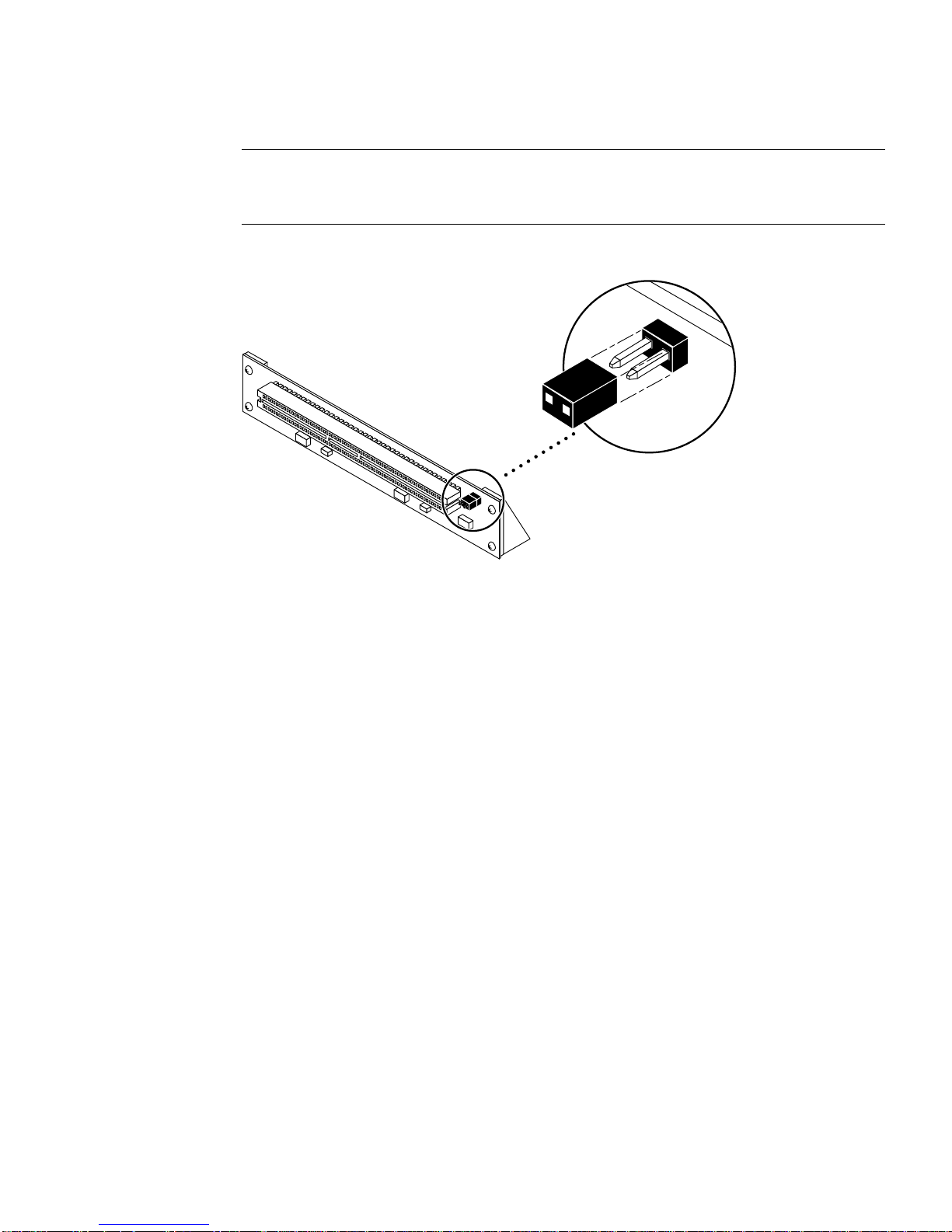
Note – If the JTAG jumper is installed, the PCI I/O board will not be recognized or
initialized during POST (power-on self-test) nor will it subsequently be recognized
by the operating system.
FIGURE 1-1 JTAG Jumper
1.3.2 Preparing for a Sun StorEdge A5x00 Installation
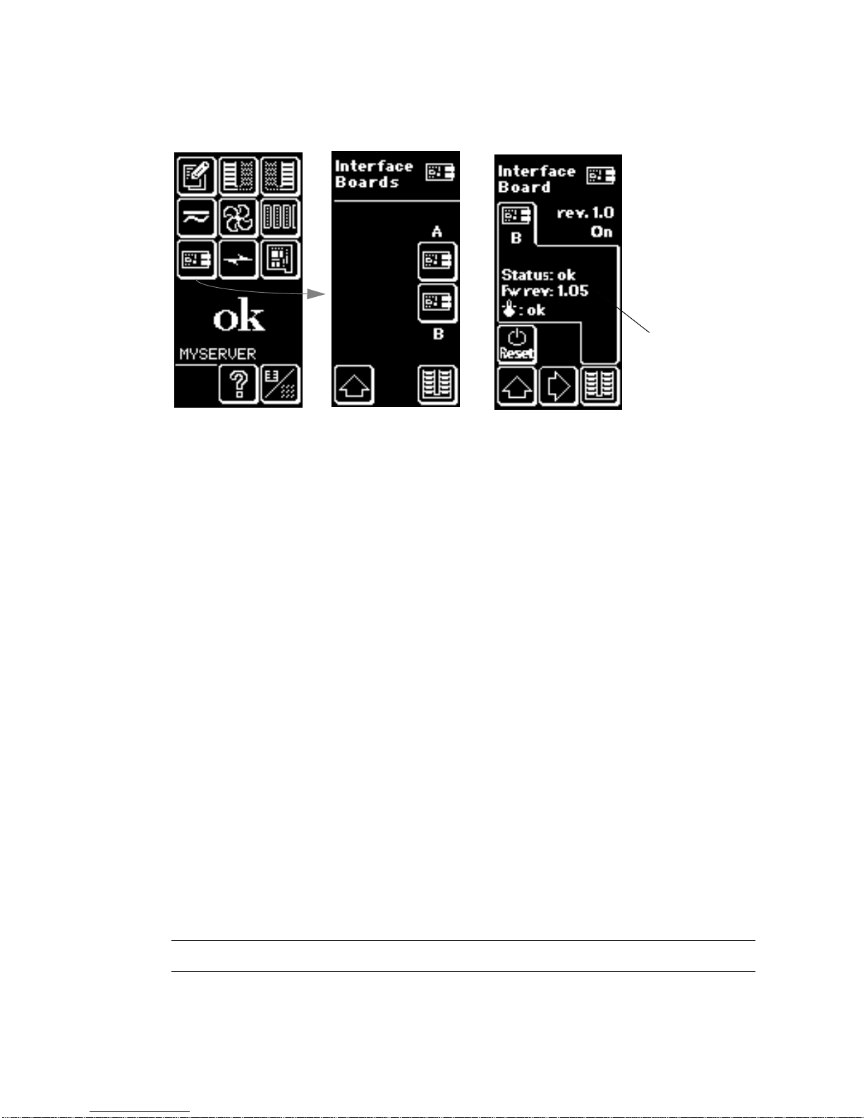
1. Use the array’s front panel module (FPM) to ensure that the firmware level of the
interface boards is at least 1.09.
Chapter -3
Page 28
Firmware revision
must be at
least 1.09
Menu screen Interface board
level 2 screen
FIGURE 1-2 Checking the Sun StorEdge A5x00 Array Interface Board Firmware Level
Interface board
level 3 screen
If the firmware level is less than 1.09, you must upgrade the firmware using an
SBus-based host system before you can connect the array to the Sun StorEdge 2G FC
PCI Single Channel Network Adapter. The instructions for obtaining the upgrade
patch are in Step 3.
2. Determine which version of the Solaris™ operating environment you are using.
Look at the /etc/release file and make sure the operating environment installed
is at least Solaris 8. If you do not have an /etc/release file, you probably need to
upgrade you operating environment to at least Solaris 8.
3. Get the required software:
■ qlc driver
■ SunVTS™
a. Go to the http://www.sun.com/products-n-solutions/hardware/docs
Web site, click Storage and then click Adapters and read the Sun StorEdge 2G
FC PCI Single Channel Network Adapter Product Notes to obtain software patch
IDs.
b. Download the software patches from the URL listed in the Sun StorEdge 2G FC
PCI Single Channel Network Adapter Product Notes or, for updates, go to:
http://sunsolve.sun.com.
Contact your support service provider if you cannot access these Web sites.
Note – Be sure to read and follow the directions in the README file for each patch.
-4 Sun StorEdge 2G FC PCI Single Channel Network Adapter Installation Guide • May 2002
Page 29

4. Log in as root on your system.
5. Verify that the SUNWses, SUNWssad, and SUNWvts packages have been installed
on your system.
Use the /usr/bin/pkginfo command and grep for each of the above packages.
For example:
# /usr/bin/pkginfo | grep SUNWvts
system SUNWvts Online Validation Test Suite
If you are missing any of these patches, you can get them from the Updates for
Solaris Operating Environment from your Solaris operating environment distribution.
6. Exit the operating environment.
To inform any mounted users that the system will be going down, use the shutdown
command. Otherwise, use the init 0 command. See the man pages for these
commands or the Solaris AnswerBook online documentation.
7. Power off the system.
Refer to the service documentation that came with your system.
Caution – Do not disconnect the power cord at this time. This connection provides
the ground path necessary to remove and install printed circuit boards and
components without damage.
8. Choose a slot into which to install the Network Adapter.
Follow the procedures in the documentation supplied with your system.
For systems that have more than one system board, you must also select and remove
a system board that has an available PCI slot. Refer to your system documentation
for specific instructions.
9. Attach the antistatic wrist strap to your wrist and to a metal component on the
system chassis.
The wrist strap between you and the chassis provides the ground path necessary to
safely remove and install the printed circuit boards and components without
damaging them.
10. For systems with a standby-type power switch, disconnect the power cord.
Standby-type power switches have a icon.
11. Open the system.
Refer to your system documentation for specific instructions.
Chapter -5
Page 30
Caution – If you need to remove a system board for installation, place the board on
a padded antistatic mat to prevent damage.
1.4 Installing the Network Adapter
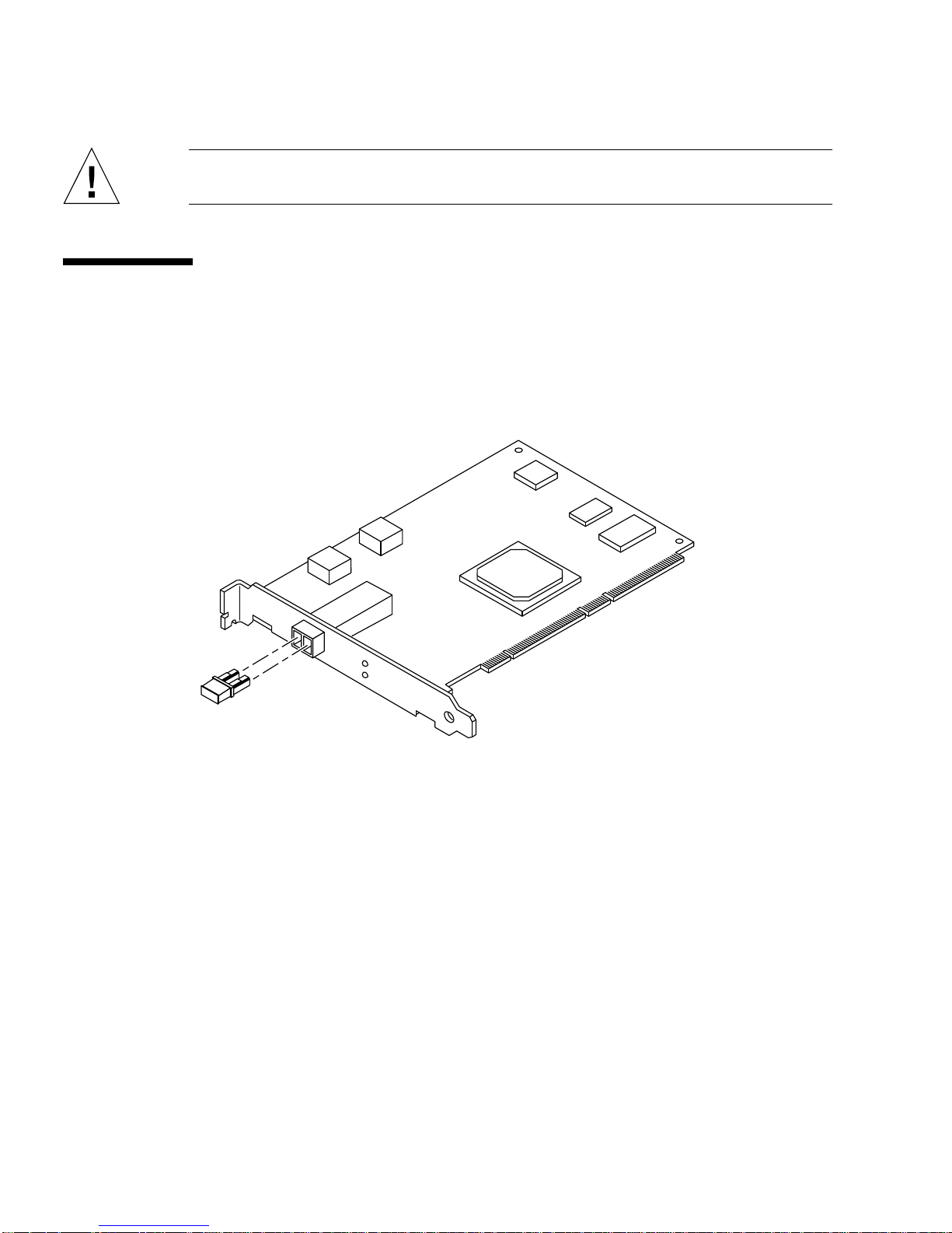
1. Pull the dust cover out of the 2 x 5 optical transceiver (OT) connector (FIGURE 1-
3).
FIGURE 1-3 Sun StorEdge PCI Single 2G Fibre Channel Network Adapter Dust Covers
2. Install the Network Adapter in the PCI slot you have chosen.
Installation details vary for each system. Refer to your system documentation for
specific instructions.
3. Reassemble the system.
Refer to your system documentation for specific instructions.
4. Disconnect the wrist strap.
5. Push the fiber optic cable connector into the OT connector until you hear a click
(FIGURE 1-4).
-6 Sun StorEdge 2G FC PCI Single Channel Network Adapter Installation Guide • May 2002
Page 31
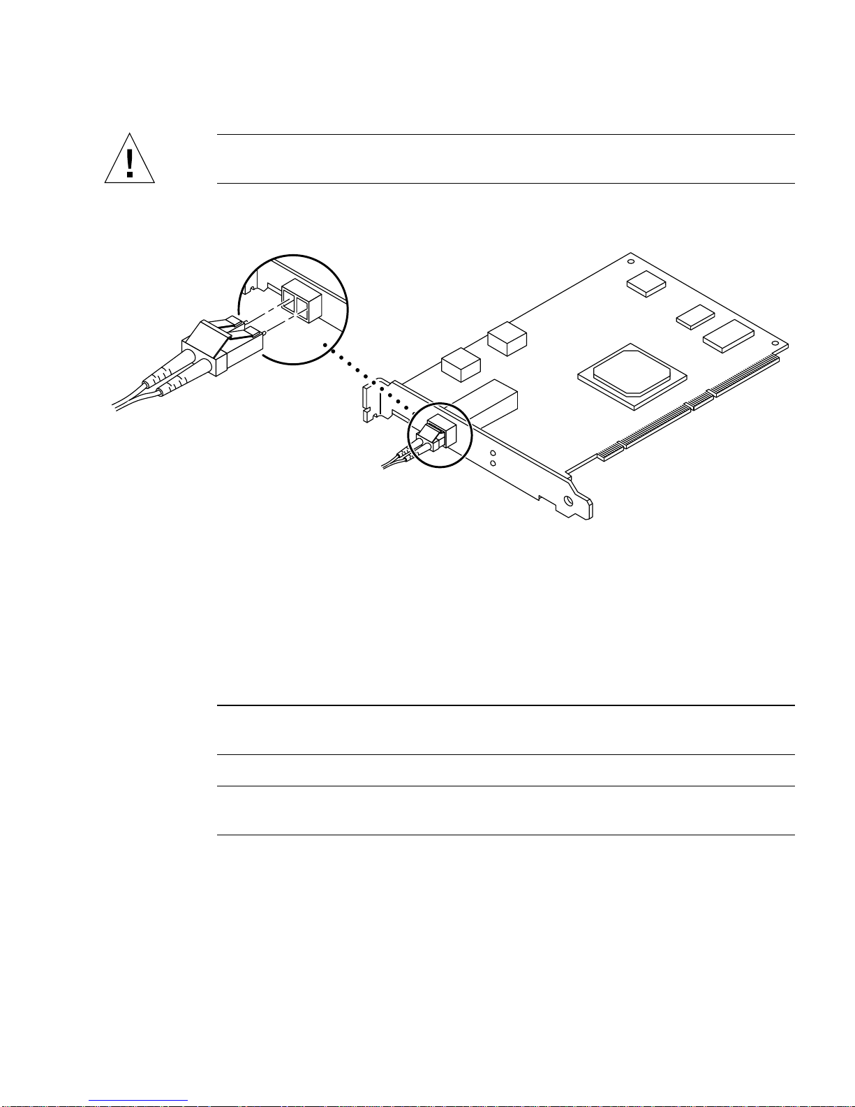
Caution – Fiber optic cables have keyed connectors; they can only be inserted into
OT connectors as shown in FIGURE 1-4.
FIGURE 1-4 Connecting a Fiber Optic Cable to an OT Connector
6. Connect the other end of the fiber optic cable to a device such as an array, switch
or hub.
Refer to the documentation that came with the device for specific instructions.
7. Power on your peripherals and then your system.
Note – When you power on the system, the LED lights on the host bus adapter
might blink. The LEDs are intended for manufacturing use only.
Note – If your system starts to reboot, interrupt the reboot process by pressing the
Stop-A keys.
The system should now be at the ok prompt. If a > prompt is showing, type n to
switch to the ok prompt.
8. Make sure that the system recognizes the Network Adapter.
Use either Method A or Method B.
Chapter -7
Page 32

a. For Method A, see CODE EXAMPLE 1-1CODE EXAMPLE 1-1 on page 1-8 and
CODE EXAMPLE 1-2 on page 1-9.
CODE EXAMPLE 1-2 on page 1-9 is a continuation of CODE EXAMPLE 1-1 on page 1-8.
b. For Method B, see FIGURE 1-7.
CODE EXAMPLE 1-1 System Recognition of the Network Adapter, Method A, Part 1
{6} ok show-devs
/counter-timer@13,1c00
...
/counter-timer@b,1c00
/pci@b,2000
/pci@b,4000
/counter-timer@a,1c00
/fhc@a,f8800000
/pci@a,2000
/pci@a,4000
/counter-timer@3,3c00
/sbus@3,0
/counter-timer@2,3c00
/fhc@2,f8800000
/sbus@2,0
/SUNW,UltraSPARC-II@7,0
/SUNW,UltraSPARC-II@6,0
/fhc@6,f8800000
/central@1f,0
/virtual-memory
/memory@0,0
/aliases
/options
/openprom
/chosen
/packages
/pci@13,4000/SUNW,isptwo@3
/pci@13,4000/SUNW,isptwo@3/st
/pci@13,4000/SUNW,isptwo@3/sd
/fhc@12,f8800000/sbus-speed@0,500000
/fhc@12,f8800000/eeprom@0,300000
/fhc@12,f8800000/flashprom@0,0
/fhc@12,f8800000/environment@0,400000
/fhc@12,f8800000/ac@0,1000000
/pci@12,2000/SUNW,qlc@2
/pci@12,2000/SUNW,qlc@2/fp@0,0
/pci@12,2000/SUNW,qlc@2/fp@0,0/disk
-8 Sun StorEdge 2G FC PCI Single Channel Network Adapter Installation Guide • May 2002
Page 33

CODE EXAMPLE 1-2 System Recognition of the Network Adapter, Method A, Part 2
{6} ok apply show-children /pci@12,2000/SUNW,qlc@2
LiD HA LUN --- Port WWN --- ----- Disk description ----43 6d 0 210000203718b2e1 SEAGATE ST318203FSUN18G 114A
44 6c 0 21000020376501bf SEAGATE ST318304FSUN18G 012D
45 6b 0 21000020376502fa SEAGATE ST318304FSUN18G 012D
46 6a 0 2100002037651a7e SEAGATE ST318304FSUN18G 0726
4d 5a 0 508002000002f231 SUN SENA 1.09
40 72 0 2100002037651f78 SEAGATE ST318304FSUN18G 0726
42 6e 0 2100002037651cb4 SEAGATE ST318304FSUN18G 0726
{6} ok
In CODE EXAMPLE 1-2 on page 1-9, /pci@12,2000/SUNW,qlc@2 is the path to the
Single Channel FC adapter board. The WorldWide Names of the Sun StorEdge
A5000 Array and the disk drives inside are displayed.
CODE EXAMPLE 1-3 System Recognition of the Network Adapter, Method B
{6} ok select /pci@12,2000/SUNW,qlc@2
{6} ok show-children
LiD HA LUN --- Port WWN --- ----- Disk description ----43 6d 0 210000203718b2e1 SEAGATE ST318203FSUN18G 114A
44 6c 0 21000020376501bf SEAGATE ST318304FSUN18G 012D
45 6b 0 21000020376502fa SEAGATE ST318304FSUN18G 012D
46 6a 0 2100002037651a7e SEAGATE ST318304FSUN18G 0726
4d 5a 0 508002000002f231 SUN SENA 1.09
40 72 0 2100002037651f78 SEAGATE ST318304FSUN18G 0726
42 6e 0 2100002037651cb4 SEAGATE ST318304FSUN18G 0726
{6} ok
Note – The probe-scsi-all command does not function identically on all
platforms, and does not in all cases probe for fiber channel devices. The
probe-fcal-all command exists only on Sun Enterprise™ systems.
9. Reboot your system using the boot -r command.
Chapter -9
Page 34

1.5 Testing the Installation
1.5.1 SunVTS
Refer to the SunVTS documents in TABLE 1-1 on page 1-10.
TABLE 1-1 Sun VTS Documents
Application Title Part Number
Diagnostic Testing SunVTS 4.5 User’s Guide 816-1575
SunVTS 4.5 Test Reference 816-1576
SunVTS is a diagnostic program that exercises your system to verify the
functionality, reliability, and configuration of your Network Adapter. You will need
to install both the 32- and 64-bit versions of SunVTS.
1.5.2 Testing Procedure
1. To invoke SunVTS locally on a system running CDE, type the following as root:
# cd /opt/SUNWvts/bin
# ./sunvts
2. From the SunVTS menus select the following:
a. Select devices None and select intervention.
b. Select mode Functional test.
c. Select Host Adapter qlcx where x is the qlc number of the qlc port you want
to run this test against.
d. If you want to run the external loopback test, place a loopback plug into the qlc
port that you want to test.
If you do not have an external loopback plug, you can make one by taking apart
a fiber cable and plug the same cable into the transmitter and receiver of the qlc
port.
-10 Sun StorEdge 2G FC PCI Single Channel Network Adapter Installation Guide • May 2002
Page 35

e. Right click on the qlc test and select Test Parameter Options.
f. Enable the External Loopback Test.
Note – If you do not use a loopback plug, you can connect the qlc port to storage
devices. In such a case, you will be testing both the qlc and the entire fiber loop.
g. Select Start to start the test.
Note – If you select only the external loopback test, the different version diagnostic
tests will not be run and the delay time between tests will be set to zero. This is a
good way to test your fiber loop if you leave the qlc port attached to storage devices.
Chapter -11
Page 36

-12 Sun StorEdge 2G FC PCI Single Channel Network Adapter Installation Guide • May 2002
Page 37

APPENDIX
A
Specifications
A.1 PCI Card
The Sun StorEdge 2G FC PCI Single Channel Network Adapter is a Fibre Channel
PCI card with one onboard optical transceiver. This Network Adapter is PCI Version
2.2 compliant.
A.2 Fibre Channel Interface Specifications
TABLE A-1 Fibre Channel Specifications
Specification Value
ANSI Standards Fibre Channel FC-PH X3.230-1995
SCSI Fibre Channel Protocol X3.269-1996
Optical transceiver 200 MBytes/sec (2 Gbits/sec), full duplex
Shortwave laser, Module Definition 5
Fiber cable type 50 or 62.5 micrometer multimode
Maximum cable length 150 meters for 62.5 micrometer multimode
300 meters for 50 micrometer multimode
-1
Page 38

A.3 Performance Specifications
The following specifications must be verified.
TABLE A-2 Performance Specifications
Feature Specification
PCI clock 66 MHz maximum
PCI data burst transfer rate 528 MBytes/sec burst rate
FC-AL transfer rate payload 200 MBytes/sec
PCI data/address lines AD63-0
PCI modes Master/slave
Capacitance per PCI signal line ≤10 pF, except for CLK between 5 to 12 pF and
IDSEL ≤8pF
FC Interface 2 Gbit optical (2.125 Gbits/sec)
-2 Sun StorEdge 2G FC PCI Single Channel Network Adapter Installation Guide • May 2002
Page 39

A.4 Power Requirements
TABLE A-3 Power Requirements
Specification Rating
Voltage and current 5V 5%,3A
Ripple 100 mV
A.5 Physical Dimensions
TABLE A-4 Physical Dimensions
Height Width Depth Weight
15 mm 106.68 mm 174.63 mm 100 g
0.6 in. 4.2 in. 6.875 in. 3.6 oz.
Appendix -3
Page 40

A.6 Regulatory Compliance
TABLE A-5 Requirements Met or Exceeded by the Network Adapter
Category Rating
Safety UL 1950
CSA 950
TUV EN 60950
Class 1 laser requirements per CFR 21, Part 1040 and IEC 825
RFI/EMI FCC Class B
DOC Class B
VCCI Class B
EMC Directive (89/336/EEC), EN55022
Immunity EMC Directive (89/336/EEC), EN55082-1
-4 Sun StorEdge 2G FC PCI Single Channel Network Adapter Installation Guide • May 2002
Page 41

A.7 PCI-X Edge Connector Pin Definitions:
32-Bit Cards
TABLE A-6 PCI Edge Connector Pin Definitions, 32-Bit Cards (Top)
Pin Description Pin Description Pin Description
1 -12V 22 GND 43 +3.3V
2 TCK 23 AD27 44 C_BE1
3 GND 24 AD25 45 AD14
4 TDO 25 +3.3V 46 GND
5 +5V 26 C_BE3 47 AD12
6 +5V 27 AD23 48 AD10
7 INTB 28 GND 49 GND
8 INTD 29 AD21 50 KEYWAY
9 GND (PRSNT1) 30 AD19 51 KEYWAY
10 RESERVED 31 +3.3V 52 AD08
11 GND (PRSNT2) 32 AD17 53 AD07
12 KEYWAY 33 C_BE2 54 +3.3V
13 KEYWAY 34 GND 55 AD05
14 RESERVED 35 IRDY 56 AD03
15 GND 36 +3.3V 57 GND
16 CLK 37 DEVSEL 58 AD01
17 GND 38 GND 59 +5V
18 REQ 39 LOCK 60 ACK64
19 +3V/+5V 40 PERR 61 +5V
20 AD31 41 +3.3V 62 +5V
21 AD29 42 SERR
Appendix -5
Page 42

TABLE A-7 PCI Edge Connector Pin Definitions, 32-Bit Cards(Bottom)
Pin Description Pin Description Pin Description
1 TRST 22 AD28 43 PAR
2 +12V 23 AD26 44 AD15
3 TMS 24 GND 45 +3.3V
4 TDI 25 AD24 46 AD13
5 +5V 26 IDSEL 47 AD11
6 INTA 27 +3.3V 48 GND
7 INTC 28 AD22 49 AD09
8 +5V 29 AD20 50 KEYWAY
9 RESERVED 30 GND 51 KEYWAY
10 +5V 31 AD18 52 C_BE0
11 RESERVED 32 AD16 53 +3.3V
12 KEYWAY 33 +3.3V 54 AD06
13 KEYWAY 34 FRAME 55 AD04
14 RESERVED 35 IGND 56 GND
15 RST 36 TRDY 57 GND
16 +5V 37 GND 58 AD02
17 GNt 38 STOP 59 +5V
18 GND 39 +3.3V 60 REQ64
19 RESERVED 40 SDONE 61 +5V
20 AD30 41 SBO 62 +5V
21 +3.3V 42 GND
-6 Sun StorEdge 2G FC PCI Single Channel Network Adapter Installation Guide • May 2002
Page 43

A.8 PCI-X Edge Connector Pin Definitions:
64-Bit Cards
TABLE A-8 PCI Expansion Board Pinout—Universal Board
Pin Side B Side A Pin Side B Side A
1 -12V TRST# 26 C/BE[3]# IDSEL
2 TCK +12V 27 AD[23] +3.3V
3 Ground TMS 28 Ground AD[22]
4 TDO TDI 29 AD[21] AD[20]
5 +5V +5V 30 AD[19] Ground
6 +5V INTA# 31 +3.3V AD[18}
7 INTB# INTC# 32 AD[17] AD[16]
8 INTD# +5V 33 C/BE[2]# +3.3V
9 PRSNT1# Reserved 34 Ground FRAME#
10 Reserved +V
11 PRSNT2# Reserved 36 +3.3V TRDY#
12 Keyway Keyway 37 DEVSEL# Ground
13 Keyway Keyway 38 Ground STOP#
14 Reserved 3.3Vaux 39 LOCK# +3.3V
15 Ground RST# 40 PERR# SDONE
16 CLK +V
17 Ground GNT# 42 SERR# Ground
18 REQ# Ground 43 +3.3V PAR
19 +V
20 AD[31] AD[30] 45 ad[14] +3.3V
21 AD[29] +3.3V 46 Ground AD[13]
22 Ground AD[28] 47 AD[12] AD[11]
23 AD[27] AD[26] 48 AD[10] Ground
24 AD[25] Ground 49 M66EN AD[09]
25 +3.3V AD[24] 50 Keyway Keyway
I/O PME# 44 C/BE[1]# AD[15]
I/O 35 IRDY# Ground
I/O 41 +3.3V SBO#
Appendix -7
Page 44

TABLE A-9 PCI Expansion Board Pinout—Universal Board
Pin Side B Side A Pin Side B Side A
51 Keyway Keyway 76 Ground AD[52]
52 AD[08] C/BE[0]# 77 AD[51] AD[50]
53 AD[07] +3.3V 78 AD[49] Ground
54 +3.3V AD[06]# 79 +V
I/O AD[48]
55 AD[05] AD[04]# 80 AD[47] AD[46]
56 AD[03] Ground 81 AD[45] Ground
57 Ground AD[02] 82 Ground AD[44]
58 AD[01] AD[00] 83 AD[43] AD[42]
59 +V
I/O +VI/O 84 AD[41] +VI/O
60 ACK64# REQ64# 85 Ground AD[40]
61 +5V +5V 86 AD[39] AD[38]
62 +5V +5V 87 AD[37] Ground
Keyway Keyway 88 +V
I/O AD[36]
Keyway Keyway 89 AD[35] AD[34]
63 Reserved Ground 90 AD[33] Ground
64 Ground C/BE[7]# 91 Ground AD[32]
65 C/BE[6]# C/BE[5]# 92 Reserved Reserved
66 C/BE[4]# +V
I/O 93 Reserved Ground
67 Ground PAR64 94 Ground Reserved
68 AD[63] AD[62]
69 AD[61] Ground
70 +V
I/O AD[60]
71 AD[59] AD[58]
72 AD[57] Ground
73 Ground AD[56]
74 AD[55] AD[54]
75 AD[53] +V
-8 Sun StorEdge 2G FC PCI Single Channel Network Adapter Installation Guide • May 2002
I/O
Page 45

APPENDIX
B
Booting From the Network Adapter
Booting from the network adapter requires special procedures in order to enable
detection of installation devices. To boot from the small kernel image on the network
adapter, you must use either a boot/install server or a temporarily directlyconnected boot disk to enable bootability. The method using a boot install server is
the Net Install Patching method and the method using a directly-connected boot
disk is the Dump and Restore method. Both procedures should be performed by a
knowledgeable UNIX system administrator.
The two methods are explained in this appendix in the sections:
■ Section B.1 “The Net Install Method” on page B-2
■ Section B.2 “The Dump and Restore Method” on page B-8
The Dump and Restore method is more difficult than the Net Install Patching
method and you might experience complications in the loss of the boot. However,
the method is available to anyone with existing systems, whether small or large
configurations, and it provides a disk image when you have completed the process.
The Net Install Patching method requires a jump-start server and network
connectivity, and it is more suitable for large system configurations than for small
ones. This method is easier than the Dump and Restore method and mitigates the
risk of data loss.
Note – These procedures are necessary if the network adapter card driver is not
bundled with the Solaris operating environment on the boot server on the network.
Check your Solaris operating environment to determine whether the driver is
bundled with it.
Booting through a network adapter is mandatory when the host is an enterpriselevel system or other system that does not have its own directly-connected disks. It
is optional and preferable when a host has a directly-connected disk, you might
prefer to boot through the adapter because the 2 Gb connection is faster.
-1
Page 46

B.1 The Net Install Method
This section contains a bootability method that is different from the one starting at
Section B.2 “The Dump and Restore Method” on page B-8. The topics in this section
include:
■ Section B.1.1 “Overview For the Net Install Method” on page B-2
■ Section B.1.2 “To Set Up the Boot/Install Server” on page B-3
■ Section B.1.3 “To Modify the Boot Image” on page B-5
■ Section B.1.4 “To Set Up the Client” on page B-6
The procedures in this section explain how to install the Solaris operating
environment from a boot/install server onto the host with the host adapter. Any
other host on the same subnet can be set up as a boot/install server.
Note – The procedure is identical whether the you are using a boot server or an
install server.
1
Therefore, the convention used in this chapter is to refer to either type
of server as the “boot/install server.”
B.1.1 Overview For the Net Install Method
Installing a client from a boot/install server uses two images of the Solaris operating
environment:
■ A boot mini-root (which is referred to from here on as the boot image)
■ A separate install image that gets copied onto the boot disk
This procedure assumes you know how to install Solaris software over the network
as described in the Solaris installation manuals. For more information, see the man(1)
pages for the commands that are used in this procedure.
Note – While you are setting up the boot/install server, you must either have the
contents of the Solaris installation CD-ROM copied to a disk that is directlyconnected to the boot/install server or have the Solaris installation CD inserted and
mounted from an attached CD-ROM device.
1. For thedistinction betweenthese two types of server, see the Solaris systemadministration documentation.
-2 Sun StorEdge 2G FC PCI Single Channel Network Adapter Installation Guide • May 2002
Page 47

You need to enable bootability using a boot/install server to make both images
aware of the host adapter. At the start of the procedure, the system administrator
downloads the driver and all required patches to an exported directory on the
boot/install server.
The following steps explain the process. For actual instructions, begin with
Section B.1.2 “To Set Up the Boot/Install Server” on page B-3.
1. The boot image is copied from a Solaris CD-ROM or from another location onto a
disk that is attached to a boot/install server.
2. The driver package is added to the boot image.
You add the driver package to the boot image so that the boot/install server can
then send and receive data through the host adapter on the boot client.
3. The client boots from the boot/install server, the interactive suninstall(1M)
application starts, and the system administrator provides configuration information
requested at the prompts.
4. After the system administrator provides all configuration information requested by
the installation program, the installation of the Solaris operating environment
begins.
5. The install image is copied to the client.
6. Before a reboot, while the client is still booted from the boot image mini-root, the
driver and any needed patches are copied from the boot/install server and then
installed in the install image.
You install the driver package and patch the install image so that the host will be
able to see the host adapter after a reboot.
Note – You can not use Jump Start until you modify the install image.
7. The host boots from the boot disk through the network adapter.
B.1.2 To Set Up the Boot/Install Server
1. Switch users to root on the host to be used as the boot/install server.
% su
Password:
#
Appendix -3
Page 48

2. Use the setup_install_server(1M) command from the Tools directory in the
location where the Solaris software resides.
As shown in the following screen example, the setup_install_server command
copies the boot image to a directory on the boot/install server. (The boot directory is
named /boot_dir
/<original_OS_dir>/Boot in the example.) The example shows the
command being run from the Tools directory on a mounted Solaris 8 installation
CD-ROM.
# cd /cdrom/cdrom0/s0/Solaris_8/Tools
# ./setup_install_server -t /<original_OS_dir>/Boot /<new_OS_copy_dir>
3. Download the driver packages and the accompanying README file from Sun’s
download center into the /<export_public> directory on the boot/install server.
a. Go to the download center URL specified in the instructions on how to
download the network adapter driver in the product notes.
b. Download the README file.
c. Remove any previously-installed packages for this network adapter as
instructed in the README.
d. Download the packages as described in the instructions in the release notes.
e. Use the uncompress(1M) and tar(1M) commands to uncompress and expand
the packages in the tar file, as instructed in the README.
Caution – Do not use the pkgadd(1M) command line that is given in the README to
install the packages. See Section B.1.3 “To Modify the Boot Image” on page B-5 to
install relocatable versions of the packages.
4. Download the required patch(es) and the accompanying README file(s) from
sunsolve.sun.com into the /<export_public> directory on the boot/install server.
a. See the release notes for a list of required patches.
b. Go to the URL specified in the instructions on how to download the network
adapter driver required patch(es) in the release notes.
c. Download the README file.
d. Remove any previously-installed related-patches that may be specified in the
README.
e. Download the patch(es) as described in the instructions in the release notes.
-4 Sun StorEdge 2G FC PCI Single Channel Network Adapter Installation Guide • May 2002
Page 49

f. Use the uncompress(1M) and tar(1M) commands to uncompress and expand
the patch(es) in the tar file, as instructed in the README.
Caution – Do not use the patchadd(1M) command line that is given in the README
to install the patch(es). See Section B.1.3 “To Modify the Boot Image” on page B-5 to
install relocatable versions of the patch(es).
B.1.3 To Modify the Boot Image
1. Install the driver packages into the boot image.
The following example installs all packages previously downloaded into the
/<export_public> directory.
Note – Refer to the install_order file for the proper order in which to install the
packages. You must follow this order for a successful installation so the driver will
run.
# cd /<export_public>
# pkgadd -R /<new_OS_copy_dir>/Boot -d .
2. Install any needed patches into the boot image.
The following example installs any patch(es) that were previously downloaded into
the /<export_public> directory. Repeat the patchadd command for all the patches
you need to add.
# cd /<export_public>
# patchadd -C /<new_OS_copy_dir>/Boot -M /<export_public> <patch_ID>
3. Make sure the host name, its IP address, and its Ethernet address have been added
to the name service (/etc files, NIS, or NIS+).
4. Run the add_install_client(1M) command to add the host with the host
adapter as a boot/install client.
The example shows the add_install_client command followed by the name of
the host followed by its platform name.
# add_install_client <host_name> <platform_name>
Appendix -5
Page 50
Note – You can find the platform name by running the uname command with the
-m option on the host that has the host adapter.
5. Log out of the boot/install server.
B.1.4 To Set Up the Client
1. Bring the client host (with the host adapter) down to the ok prompt at run level 0.
See the Solaris system administration documentation for the commands that can be
used with different configurations. The following example uses the shutdown(1M)
command.
# shutdown
...
ok
Caution – Do not reboot the boot/install server.
2. Boot the host from the net.
ok boot net
The Solaris interactive installation program runs from the boot/install server.
3. Respond to the prompts according to your configuration, as instructed in the
Solaris installation guide.
Make sure to specify the new boot disk as the destination for the operating
environment installation.
4. When prompted to choose between automatic reboot or manual reboot, click the
Manual Reboot button, complete the remaining question, and start the
installation.
This question offering a choice between automatic and manual reboot is the last
question before the installation starts. If you are using the suninstall program,
choose boot manual.
-6 Sun StorEdge 2G FC PCI Single Channel Network Adapter Installation Guide • May 2002
Page 51

5. Mount the /<export_public> directory which contains the driver packages and any
needed patches onto the /mnt directory mount point.
Enter the mount command followed by the hostname of the boot/install server,
followed by a colon (:), followed by /<export_public> followed by /mnt. The
following example uses boot_install_server as the name of the boot/install server.
# mount boot_install_server:/<export_public> /a/mnt
6. Install the driver packages into the install image.
The following example installs all packages previously downloaded into the
/<export_public> directory. When prompted, install the packages in the order of
SUNWsan, SUNWcfpl, SUNWcfplx.
# cd /a/mnt
# pkgadd -R /a -d .
7. Install any needed patches into the boot image.
The following example installs all patch(es) that were previously downloaded into
the /<export_public> directory.
Note – Install the patches in their sequential numeric order to ensure the installation
is successful.
# cd /a/mnt
# patchadd -R /a <patch_ID>
8. Bring the system down to the ok prompt at run level 0.
# halt
9. Reboot the host from the newly installed operating environment.
ok boot -r
Appendix -7
Page 52

B.2 The Dump and Restore Method
This section contains a bootability method that is different from the one starting at
Section B.1 “The Net Install Method” on page B-2. The topics in this section include:
■ Section B.2.1 “Overview Of the Dump and Restore Method” on page B-8
■ Section B.2.2 “Partitioning the New Boot Disk the Same As the Temporary Boot
Disk” on page B-8
■ Section B.2.3 “To Create File Systems on the New Boot Disk” on page B-18
■ Section B.2.4 “To Create the New Boot Files” on page B-18
B.2.1 Overview Of the Dump and Restore Method
To enable bootability using a temporary boot disk, a boot disk must be directly
connected, at least temporarily, to the host. The boot disk must have the following
installed:
■ The Solaris operating environment.
■ The network adapter driver packages and any needed patches
See the release notes for how to download and install the driver packages and
any needed patches.
Note – The initial boot disk can be removed if it is not needed after the boot disk is
enabled.
Note – The examples in this section show disk 0 as the directly-connected boot disk,
and disk 2 as the designated new boot disk that is connected through the host
adapter.
B.2.2 Partitioning the New Boot Disk the Same As the
Temporary Boot Disk
There are several sub procedures required to complete the first phase of enabling
bootability from a temporarily connected boot disk. These sub procedures include:
■ Section B.2.2.1 “To Prepare To Partition the New Disk” on page B-9
■ Section B.2.2.2 “To Record the Partition Layout” on page B-9
-8 Sun StorEdge 2G FC PCI Single Channel Network Adapter Installation Guide • May 2002
Page 53
■ Section B.2.2.3 “To Change To the New Boot Disk” on page B-12
■ Section B.2.2.4 “To Specify Slices On the New Boot Disk” on page B-13
■ Section B.2.2.5 “To Label the New Boot Disk” on page B-17
B.2.2.1 To Prepare To Partition the New Disk
1. Switch users to root on the host with the host adapter.
% su
Password:
#
2. If the driver and any needed patches are not already installed, download the
driver package from Sun’s download center and install it on the host, following
the instructions in the README file that comes with the driver.
To download the driver, follow the instructions in the release notes.
3. Reboot using the reboot(1M) command with the -r option.
# reboot -- -r
4. Log into the host as root.
B.2.2.2 To Record the Partition Layout
After you log back into the host, you can record the layout of the partitions, or slices,
on the system boot disk.
1. Enter the format(1M) command.
If needed, see the format man page and the instructions on adding a disk and
using the format command in the Solaris administration documentation.
Appendix -9
Page 54

Note – These examples use disk 0 as the temporary disk (c0t0d0) and disk 2
(c7t16d0) as the new boot disk.
# format
Searching for disks...done
AVAILABLE DISK SELECTIONS:
0. c0t1d0 <SUN18G cyl 7506 alt 2 hd 19 sec 248>
/pci@8,600000/SUNW,qlc@4/fp@0,0/ssd@w2100002037e43542,0
1. c0t2d0 <SUN36G cyl 24620 alt 2 hd 27 sec 107>
/pci@8,600000/SUNW,qlc@4/fp@0,0/ssd@w21000020374205a1,0
2. c7t16d0 <SUN36G cyl 24620 alt 2 hd 27 sec 107>
/pci@8,600000/SUNW,qlc@1/fp@0,0/ssd@w500000e01002b7c1,0
3. c7t17d0 <SUN36G cyl 24620 alt 2 hd 27 sec 107>
/pci@8,600000/SUNW,qlc@1/fp@0,0/ssd@w500000e0100357c1,0
4. c7t18d0 <SUN36G cyl 24620 alt 2 hd 27 sec 107>
/pci@8,600000/SUNW,qlc@1/fp@0,0/ssd@w500000e010032331,0
5. c7t19d0 <drive not available: formatting>
/pci@8,600000/SUNW,qlc@1/fp@0,0/ssd@w500000e010032661,0
6. c7t20d0 <SUN36G cyl 24620 alt 2 hd 27 sec 107>
/pci@8,600000/SUNW,qlc@1/fp@0,0/ssd@w500000e0100369e1,0
Specify disk (enter its number):
2. Make a note of the device path name of the new boot disk.
For example, for disk 2, the new boot disk in this example, the device path name
shown is:/pci@8,600000/SUNW,qlc@1/fp@0,0. You use this information later
in Step 4 in Section B.2.4.4 “To Specify the New Boot Disk as the Boot Device.” on
page B-22.
Note – The qlc number changes, depending on the type of host and slot in use.
3. Specify the disk where the operating system is installed on the temporary boot
disk.
The following screen example specifies disk 2.
Specify disk (enter its number): 2
-10 Sun StorEdge 2G FC PCI Single Channel Network Adapter Installation Guide • May 2002
Page 55

4. Enter the partition command to bring up the PARTITION MENU.
format> partition
PARTITION MENU:
0 - change ‘0’ partition
1 - change ‘1’ partition
2 - change ‘2’ partition
3 - change ‘3’ partition
4 - change ‘4’ partition
5 - change ‘5’ partition
6 - change ‘6’ partition
7 - change ‘7’ partition
select - select a predefined table
modify - modify a predefined partition table
name - name the current table
print - display the current table
label - write partition map and label to the disk
!<cmd> - execute <cmd>, then return
quit
partition>
5. Enter the print command to display the partition table for the specified disk.
partition>
print
Current partition table (original):
Total disk cylinders available: 3880 + 2 (reserved cylinders)
Part Tag Flag Cylinders Size Blocks
0 root wm 0 - 1937 2.00GB (1938/0/0) 4186080
1 swap wu 1938 - 2908 1.00GB (971/0/0) 2097360
2 backup wm 0 - 3879 4.00GB (3880/0/0) 8380800
3 unassigned wm 0 0 (0/0/0) 0
4 unassigned wm 0 0 (0/0/0) 0
5 unassigned wm 0 0 (0/0/0) 0
6 unassigned wm 0 0 (0/0/0) 0
7 home wm 2909 - 3879 1.00GB (971/0/0) 2097360
As shown in the example, the temporary boot disk has three slices defined: 0
(root), 1 (swap), and 7 (home) with sizes, 2.00GB, 1.00GB, and 1.00GB.
Appendix -11
Page 56

6. Record the layout (sizes and numbers) assigned to the slices on the temporary
boot disk, and enter quit when done.
partition> quit
FORMAT MENU:
disk - select a disk
type - select (define) a disk type
partition - select (define) a partition table
current - describe the current disk
format - format and analyze the disk
repair - repair a defective sector
label - write label to the disk
analyze - surface analysis
defect - defect list management
backup - search for backup labels
verify - read and display labels
save - save new disk/partition definitions
inquiry - show vendor, product and revision
volname - set 8-character volume name
!<cmd> - execute <cmd>, then return
quit
format>
As shown in the previous example, the quit command returns you to the
FORMAT MENU.
B.2.2.3 To Change To the New Boot Disk
After you record the partition layout, change to the new boot disk.
1. At the format> prompt, type disk to change the current disk to the new boot
disk.
-12 Sun StorEdge 2G FC PCI Single Channel Network Adapter Installation Guide • May 2002
Page 57

2. Enter the number of the disk to be formatted after the disk command.
The following screen example uses disk 2. The FORMAT MENU appears.
format> disk 2
selecting c7t16d0
[disk formatted]
FORMAT MENU:
disk - select a disk
type - select (define) a disk type
partition - select (define) a partition table
current - describe the current disk
format - format and analyze the disk
repair - repair a defective sector
label - write label to the disk
analyze - surface analysis
defect - defect list management
backup - search for backup labels
verify - read and display labels
save - save new disk/partition definitions
inquiry - show vendor, product and revision
volname - set 8-character volume name
!<cmd> - execute <cmd>, then return
quit
format>
3. Make a note of the device name of the disk.
The device name of the disk in the previous screen example is c7t16d0.
B.2.2.4 To Specify Slices On the New Boot Disk
After you change to the new boot disk, specify one slice on the new boot disk for
every slice on the temporary boot disk. The following examples specify the root slice
0 on the new boot disk to match slice 0 on the temporary boot disk.
Appendix -13
Page 58

1. Enter the partition command to bring up the PARTITION MENU.
format> p
PARTITION MENU:
0 - change ‘0’ partition
1 - change ‘1’ partition
2 - change ‘2’ partition
3 - change ‘3’ partition
4 - change ‘4’ partition
5 - change ‘5’ partition
6 - change ‘6’ partition
7 - change ‘7’ partition
select - select a predefined table
modify - modify a predefined partition table
name - name the current table
print - display the current table
label - write partition map and label to the disk
!<cmd> - execute <cmd>, then return
quit
partition>
2. Enter the number of the slice to be defined.
Slice 0 is specified in the following example. As shown, the partition table for the
new boot disk displays.
partition> 0
Current partition table (original):
Total disk cylinders available: 24620 + 2 (reserved cylinders)
Part Tag Flag Cylinders Size Blocks
0 root wm 0 - 90 128.37MB (91/0/0) 262899
1 swap wu 91 - 181 128.37MB (91/0/0) 262899
2 backup wu 0 - 24619 33.92GB (24620/0/0) 71127180
3 unassigned wm 0 0 (0/0/0) 0
4 unassigned wm 0 0 (0/0/0) 0
5 unassigned wm 0 0 (0/0/0) 0
6 usr wm 182 - 24619 33.67GB (24438/0/0) 70601382
7 unassigned wm 0 0 (0/0/0) 0
Enter partition id tag[root]:
-14 Sun StorEdge 2G FC PCI Single Channel Network Adapter Installation Guide • May 2002
Page 59

3. Enter the partition ID tag.
The following example shows a question mark (?) entered after the prompt. The
list of accepted partition id tags displays. The example then shows the default
partition id tag of root accepted by pressing the Return key.
Enter partition id tag[root]: ?
Expecting one of the following: (abbreviations ok):
unassigned boot root swap
usr backup stand var
Enter partition id tag[root]:
Enter partition permission flags[wm]:
4. Enter the partition permission flags.
The following example shows the default permission flags wm accepted by
pressing the Return key.
Enter partition permission flags[wm]:
Enter new starting cyl[0]:
5. Enter the new starting cylinder.
The following example shows the default new starting cylinder of 0 accepted by
pressing the Return key.
Enter new starting cyl[0]:
Enter partition size[262899b, 91c, 128.37mb, 0.13gb]:
6. Enter the partition size.
The following example shows the partition size of 2.00gb entered.
Enter partition size[262899b, 91c, 128.37mb, 0.13gb]: 2.00gb
partition>
Appendix -15
Page 60

7. Enter the print command to display the updated partition table.
The following example shows that the root tag, the wm permissions flag, and the
partition size of 2.00GB are assigned to slice 0.
partition> print
Current partition table (unnamed):
Total disk cylinders available: 24620 + 2 (reserved cylinders)
Part Tag Flag Cylinders Size Blocks
0 root wm 0 - 1451 2.00GB (1452/0/0) 4194828
1 swap wu 91 - 181 128.37MB (91/0/0) 262899
2 backup wu 0 - 24619 33.92GB (24620/0/0)
71127180
3 unassigned wm 0 0 (0/0/0) 0
4 unassigned wm 0 0 (0/0/0) 0
8. Repeat Step 2 through Step 7 as needed until all slices are defined as they are in
the temporary boot disk.
9. Enter the quit command to return to the FORMAT MENU.
partition> quit
FORMAT MENU:
disk - select a disk
type - select (define) a disk type
partition - select (define) a partition table
current - describe the current disk
format - format and analyze the disk
repair - repair a defective sector
label - write label to the disk
analyze - surface analysis
defect - defect list management
backup - search for backup labels
verify - read and display labels
save - save new disk/partition definitions
inquiry - show vendor, product and revision
volname - set 8-character volume name
!<cmd> - execute <cmd>, then return
quit
format>
-16 Sun StorEdge 2G FC PCI Single Channel Network Adapter Installation Guide • May 2002
Page 61
B.2.2.5 To Label the New Boot Disk
After you specify the slices on the new boot disk, label the new boot disk with the
new partition table.
1. Enter the label command
format> label
2. Enter y[es] to continue.
Ready to label disk, continue? y
3. When the labeling is complete, enter q[uit] to quit the format program.
format> q
#
Appendix -17
Page 62

B.2.3 To Create File Systems on the New Boot Disk
● Create a file system on each slice on the disk using the newfs(1M) command.
Enter the newfs command followed by the device name of the slice. In this example,
the device name for slice 0 of disk c7t16d0 is /dev/rdsk/c7t16d0s0.
# newfs /dev/rdsk/c7t16d0s0
newfs: construct a new file system /dev/rdsk/c7t16d0s0: (y/n)? y
/dev/rdsk/c7t16d0s0: 4194828 sectors in 1452 cylinders of 27 tracks, 107
sectors
2048.3MB in 46 cyl groups (32 c/g, 45.14MB/g, 7488 i/g)
super-block backups (for fsck -F ufs -o b=#) at:
32, 92592, 185152, 277712, 370272, 462832, 555392, 647952, 740512, 833072,
925632, 1018192, 1110752, 1203312, 1295872, 1388432, 1480992, 1573552,
1666112, 1758672, 1851232, 1943792, 2036352, 2128912, 2221472, 2314032,
2406592, 2499152, 2591712, 2684272, 2776832, 2869392, 2958368, 3050928,
3143488, 3236048, 3328608, 3421168, 3513728, 3606288, 3698848, 3791408,
3883968, 3976528, 4069088, 4161648,
For more information, see the section on how to create file systems in the Solaris
system administration documentation.
Do this step to create a file system on the new boot disk for every slice on the
temporary boot disk. When you are finished, go to Section B.2.4.3 “To Copy the
Contents of Non-root File Systems onto the New Boot Disk” on page B-21.
B.2.4 To Create the New Boot Files
This section has several sub procedures, including:
■ Section B.2.4.1 “To Copy the Boot Block and Root File System Contents To the
New Boot Disk” on page B-19
■ Section B.2.4.2 “To Update the vfstab File” on page B-20
■ Section B.2.4.3 “To Copy the Contents of Non-root File Systems onto the New
Boot Disk” on page B-21
■ Section B.2.4.4 “To Specify the New Boot Disk as the Boot Device.” on page B-22
-18 Sun StorEdge 2G FC PCI Single Channel Network Adapter Installation Guide • May 2002
Page 63

B.2.4.1 To Copy the Boot Block and Root File System Contents To the
New Boot Disk
1. Install the boot block on the root (/) file system of the new disk.
The following example uses the installboot(1M) command to install the boot
block. The boot block resides in the
/usr/platform/platform_name/lib/fs/ufs/bootblk directory. The example
shows invoking the uname command with the -i option between left single quotes
on the command line to specify the platform name.
# /usr/sbin/installboot /usr/platform/‘uname -i‘/lib/fs/ufs/bootblk \
/dev/rdsk/c7t16d0s0
For more information, see the instructions on how to install a boot block in the
Solaris system administration documentation.
2. Mount the root file system from slice 0 of the new boot disk onto the /mnt mount
point.
# mount /dev/dsk/c7t16d0s0 /mnt
3. Use the ufsdump(1M) and ufsrestore(1M) commands to copy the contents of
the root file system from the temporary boot disk to the root slice of the new boot
disk (on the /mnt mount point).
# ufsdump 0f - /dev/rdsk/c0t0d0s0 | ( cd /mnt; ufsrestore rf -)
DUMP: Writing 32 Kilobyte records
DUMP: Date of this level 0 dump: Tue 19 Feb 2002 02:44:35 PM PST
DUMP: Date of last level 0 dump: the epoch
DUMP: Dumping /dev/rdsk/c7t16d0s0 (hba2-81:/) to standard
output.
DUMP: Mapping (Pass I) [regular files]
DUMP: Mapping (Pass II) [directories]
DUMP: Estimated 1818082 blocks (887.74MB).
DUMP: Dumping (Pass III) [directories]
DUMP: Dumping (Pass IV) [regular files]
Warning: ./lost+found: File exists
DUMP: 88.77% done, finished in 0:01
DUMP: 1818046 blocks (887.72MB) on 1 volume at 1363 KB/sec
DUMP: DUMP IS DONE
#
Appendix -19
Page 64

4. Unmount the root file system on slice 0 from the /mnt mount point.
# umount /mnt
B.2.4.2 To Update the vfstab File
After you copy the boot block and root files, update the vfstab file.
1. Mount the root file system from slice 0 of the new boot disk onto the /mnt mount
point.
# mount /dev/dsk/c7t16d0 /mnt
2. Change directories to /mnt/etc and open the vfstab(4) file for editing.
The following example shows the file systems defined.
# cd /mnt/etc
# vi vfstab
...
/dev/dsk/c0t0d0s1 - - swap - no /dev/dsk/c0t0d0s0 /dev/rdsk/c0t0d0s0 / ufs 1 no /dev/dsk/c0t0d0s7 /dev/rdsk/c0t0d0s7 /home ufs 2 yes -
3. Replace the name of the temporary boot disk with the name of the new boot disk,
and then save and quit the file.
The following example shows the disk name c0t0 changed to c3t8 in the mount
table entries for slices 0, 1, and 7.
/dev/dsk/c7t16d0s1 - - swap - no /dev/dsk/c7t16d0s0 /dev/rdsk/c7t16d0s0 / ufs 1 no /dev/dsk/c7t16d0s7 /dev/rdsk/c7t16d0s7 /home ufs 2 yes -
:wq
#
-20 Sun StorEdge 2G FC PCI Single Channel Network Adapter Installation Guide • May 2002
Page 65
B.2.4.3 To Copy the Contents of Non-root File Systems onto the New
Boot Disk
1. Mount the file system onto the /mnt mount point.
This example shows the copying of the /home file system from slice 7 to the new
boot disk.
# mount /dev/dsk/c7t16d0 /mnt
2. Use the ufsdump(1M) and ufsrestore(1M) commands to copy the contents of
the file system from the temporary boot disk to the new boot disk.
# ufsdump 0f - /dev/rdsk/c0t0d0s0 | ( cd /mnt; ufsrestore rf -)
DUMP: Writing 32 Kilobyte records
DUMP: Date of this level 0 dump: Tue 19 Feb 2002 02:44:35 PM PST
DUMP: Date of last level 0 dump: the epoch
DUMP: Dumping /dev/rdsk/c7t16d0s0 (hba2-81:/) to standard
output.
DUMP: Mapping (Pass I) [regular files]
DUMP: Mapping (Pass II) [directories]
DUMP: Estimated 1818082 blocks (887.74MB).
DUMP: Dumping (Pass III) [directories]
DUMP: Dumping (Pass IV) [regular files]
Warning: ./lost+found: File exists
DUMP: 88.77% done, finished in 0:01
DUMP: 1818046 blocks (887.72MB) on 1 volume at 1363 KB/sec
DUMP: DUMP IS DONE
#
3. Unmount the file system from the /mnt mount point.
# umount /mnt
4. Repeat Step 1 through Step 3 as needed until you have copied all the file systems’
contents to the new boot disk. When finished, go to Section B.2.4.2 “To Update the
vfstab File” on page B-20.
Appendix -21
Page 66

B.2.4.4 To Specify the New Boot Disk as the Boot Device.
1. Bring the host with the host adapter down to the ok prompt at run level 0.
See the Solaris system administration documentation on shutting down a host for
the commands that can be used with different configurations. The following screen
example uses the shutdown(1M) command.
# shutdown
...
ok
2. Use the nvalias command to alias the device name of the disk to a short name
for the disk.
The following example uses
/pci@8,600000/SUNW,qlc@1/fp@0,0/disk@10,0, which was the device path
name for disk 2 in Section B.2.2.2 “To Record the Partition Layout” on page B-9.
ok nvalias disk2 /pci@8,600000/SUNW,qlc@1/fp@0,0/disk@10,0
3. Use the nvstore command to store the new alias followed by the reset all
command.
ok nvstore
ok reset-all
4. Define the new boot disk as the default boot-device.
Use the data gathered in Step 2 on page 10.
a. Enter the setenv command followed by the boot-device parameter followed
by the name of the new disk.
ok setenv boot-device disk2
b. Enter the reset command.
ok reset
-22 Sun StorEdge 2G FC PCI Single Channel Network Adapter Installation Guide • May 2002
Page 67

5. Enter the boot command with the -r option so that the Solaris operating
environment can recognize the adapter.
ok boot -r
Appendix -23
Page 68

-24 Sun StorEdge 2G FC PCI Single Channel Network Adapter Installation Guide • May 2002
 Loading...