

Sun Microsystems StorEdge N8400 Filer Installation, Configuration, And Service Manual [en, fr]
Page 1

Sun StorEdge™N8400 Filer
Installation, Configuration, and
Service Guide
Sun Microsystems, Inc.
901 San Antonio Road
Palo Alto, CA 94303
U.S.A. 650-960-1300
Part No. 806-6885-11
August 2001, Revision 01
Send comments about this document to: [email protected]
Page 2

Copyright 2001Sun Microsystems,Inc., 901San AntonioRoad, PaloAlto, CA 94303-4900 U.S.A. All rights reserved.
This productor document is distributed under licenses restricting its use, copying, distribution, and decompilation. No part of this product or
document may be reproducedin any form by any means without prior written authorization of Sun and its licensors, if any.Third-party
software,including font technology,is copyrighted and licensed from Sun suppliers.
Parts of the product may be derived from Berkeley BSD systems, licensed from the University of California. UNIX is a registered trademark in
the U.S. and other countries, exclusively licensed through X/Open Company,Ltd.
Sun, Sun Microsystems, the Sun logo, AnswerBook2, docs.sun.com, Solaris, NFS, Sun StorEdge, SunNet Manager,and Sun Enterprise are
trademarks, registeredtrademarks, or service marks of Sun Microsystems, Inc. in the U.S. and other countries. All SPARC trademarks are used
under license and are trademarks or registered trademarks of SPARCInternational, Inc. in the U.S. and other countries. Productsbearing
SPARC trademarks are based upon an architecture developed by Sun Microsystems, Inc.
The OPEN LOOK and Sun™ Graphical User Interface was developed by Sun Microsystems, Inc. for its users and licensees. Sun acknowledges
the pioneering efforts of Xerox in researchingand developing the concept of visual or graphical user interfaces for the computer industry. Sun
holds a non-exclusive license from Xerox to the Xerox Graphical User Interface, which license also covers Sun’s licensees who implement OPEN
LOOK GUIs and otherwise comply with Sun’s written license agreements.
Federal Acquisitions: Commercial Software—GovernmentUsers Subject to Standard License Termsand Conditions.
DOCUMENTATION IS PROVIDED “AS IS” AND ALL EXPRESS OR IMPLIED CONDITIONS, REPRESENTATIONS AND WARRANTIES,
INCLUDING ANY IMPLIED WARRANTYOF MERCHANTABILITY, FITNESS FOR A PARTICULARPURPOSE OR NON-INFRINGEMENT,
ARE DISCLAIMED, EXCEPT TO THE EXTENT THAT SUCH DISCLAIMERS ARE HELD TO BE LEGALLY INVALID.
Copyright 2001 Sun Microsystems, Inc., 901 San Antonio Road, Palo Alto, CA 94303-4900 Etats-Unis. Tousdroits réservés.
Ce produitou document est distribué avec des licences qui en restreignent l’utilisation, la copie, la distribution, et la décompilation. Aucune
partie de ce produit ou document ne peut être reproduite sous aucune forme, par quelque moyen que ce soit, sans l’autorisation préalable et
écrite de Sun et de ses bailleurs de licence, s’il y en a. Le logiciel détenu par des tiers, et qui comprend la technologie relative aux polices de
caractères,est protégépar un copyright et licencié par des fournisseurs de Sun.
Des parties de ce produit pourront être dérivées des systèmes Berkeley BSD licenciés par l’Université de Californie. UNIX est une marque
déposée aux Etats-Unis et dans d’autres pays et licenciée exclusivement par X/Open Company,Ltd.
Sun, Sun Microsystems, le logo Sun, AnswerBook2, docs.sun.com, Solaris, NFS, Sun StorEdge, SunNet Manager,et Sun Enterprise sont des
marquesde fabrique ou des marques déposées, ou marques de service, de Sun Microsystems, Inc. aux Etats-Unis et dans d’autrespays. Toutes
les marquesSPARC sont utilisées sous licence et sont des marques de fabrique ou des marques déposées de SPARCInternational, Inc. aux EtatsUnis et dans d’autres pays. Les produits portant les marques SPARCsont basés sur une architecture développée par Sun Microsystems, Inc.
L’interfaced’utilisation graphique OPEN LOOK et Sun™ a été développée par Sun Microsystems, Inc. pour ses utilisateurs et licenciés. Sun
reconnaîtles effortsde pionniers de Xerox pour la rechercheet le développement du concept des interfaces d’utilisation visuelle ou graphique
pour l’industrie de l’informatique. Sun détient une licence non exclusive de Xerox sur l’interface d’utilisation graphique Xerox, cette licence
couvrant également les licenciés de Sun qui mettent en place l’interface d’utilisation graphique OPEN LOOK et qui en outre se conforment aux
licences écrites de Sun.
LA DOCUMENTATION EST FOURNIE “EN L’ETAT” ET TOUTES AUTRES CONDITIONS, DECLARATIONS ET GARANTIES EXPRESSES
OU TACITESSONT FORMELLEMENT EXCLUES, DANS LA MESURE AUTORISEE PARLA LOI APPLICABLE, Y COMPRIS NOTAMMENT
TOUTE GARANTIE IMPLICITE RELATIVE A LA QUALITE MARCHANDE, A L’APTITUDE A UNE UTILISATION PARTICULIERE OU A
L’ABSENCE DE CONTREFAÇON.
Please
Recycle
Page 3

Sun StorEdge N8400 Filer
Installation, Configuration, and
Service Guide
The Sun StorEdge N8400 Filer Installation, Configuration, and Service Guide describes
how to install, configure, and perform selected troubleshooting procedures of the
Sun StorEdge™ N8400 Filer. This document is organized as follows:
■ “Reference Documentation” on page 4
■ “Accessing Sun Documentation Online” on page 4
■ “Product Overview” on page 5
■ “Starting Up the System” on page 8
■ “Initial Filer Setup” on page 10
■ “To Set Up the Initial System Configuration” on page 10
■ “To Configure for PC Network Connectivity” on page 15
■ “To Verify the Installation” on page 16
■ “Setting Up the Management LAN to Monitor the Arrays” on page 17
■ “To Set Up the Partner Group to Communicate with the Management LAN” on
page 19
■ “To Configure the Arrays for Monitoring” on page 22
■ “Configuration and Monitoring Options” on page 26
■ “Monitoring the Sun Enterprise 420R Server” on page 26
■ “Configuring the System to Monitor the Arrays” on page 26
■ “Backup Client Support” on page 29
■ “To Enable the Sun Solstice Backup Software” on page 29
■ “To Install the VERITAS NetBackup Software” on page 29
■ “Installation Troubleshooting” on page 30
■ “Explanation of Array Hot Spare Operation” on page 30
■ “Troubleshooting System Problems” on page 31
■ “Troubleshooting Array Problems” on page 34
3
Page 4

Reference Documentation
Document TItle Part Number
Sun StorEdge N8400 Filer Hardware Setup 816-2034
Sun StorEdge T3 Array Installation, Operations, and Service Manual 806-1062
Sun StorEdge T3 Array Administrator’s Guide 806-1063
Sun StorEdge T3 Array Release Notes 806-1497
Sun StorEdge N8400 and N8600 Filer Administrator’s Guide 806-6905
VERITAS NetBackup System Administrator’s Guide N/A
Accessing Sun Documentation Online
The www.sun.comsmweb site enables you to access Sun technical documentation on
the Web.
1. Access Sun web site home page on your browser.
http://www.sun.com
2. Select Products & Solutions.
3. Under Hardware, select Documentation.
■ For Sun StorEdge N8400 and N8600 documentation, sequentially select:
■ Network Storage Solutions
■ Network-Attached Storage (NAS)
■ For Sun Enterprise 420R documentation, sequentially select:
■ Servers
■ Sun Enterprise 420R
■ For Sun StorEdge T3 Array documentation, sequentially select:
■ Network Storage Solutions
■ Disk Arrays
■ Sun StorEdge[tm] T3
4 Sun StorEdge N8400 Filer Installation, Configuration, and Service Guide • August 2001
Page 5
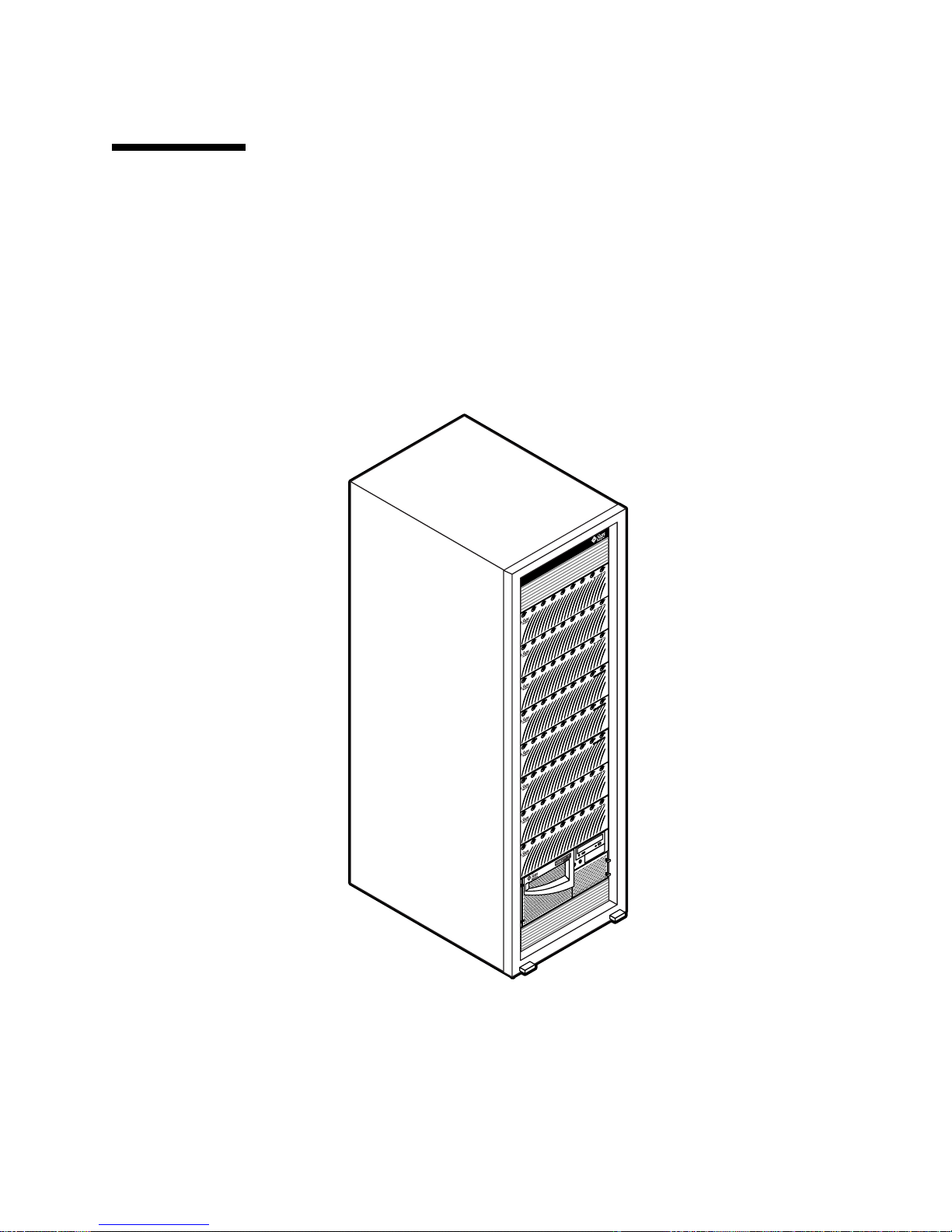
Product Overview
A network attached storage (NAS) device is an appliance that supplies disk storage
to users over a network. Moving storage from the user’s desktop to the network
maximizes data availability and security. The Sun StorEdge N8400 Filer (hereafter
referred to as “the filer”) is a NAS appliance that consists of a Sun Enterprise 420R
Server and from one to four partner groups of Sun StorEdge T3 Arrays. This equates
to one to four terabytes (Tbytes) of storage.
FIGURE 1 Sun StorEdge N8400 Filer with Maximum Storage Configuration
Sun StorEdge N8400 Filer Installation, Configuration, and Service Guide 5
Page 6

The filer is an integration of proven Sun Microsystems hardware and software to
obtain easy access to a maximum of 4 Tbytes of storage. It provides a complete file
server solution that seamlessly integrates into your network. The filer scales both
vertically and horizontally—you can add more filers to your network, or add more
storage to your filer.
The filer contains features that are designed to minimize down time, including:
■ Mirrored system disks in the Sun Enterprise 420R Server
■ Hardware redundant array of independent disks (RAID)-5 storage system
■ Redundant power supplies in both the Sun Enterprise 420R Server and each of
the Sun StorEdge T3 Arrays
Access to the filer’s disk storage is through the following industry standard file
access protocols:
■ NFS™ file system
■ Common Internet File System (CIFS)
The filer also includes a web-based administration tool that provides an easy-to-use
graphical user interface (GUI).
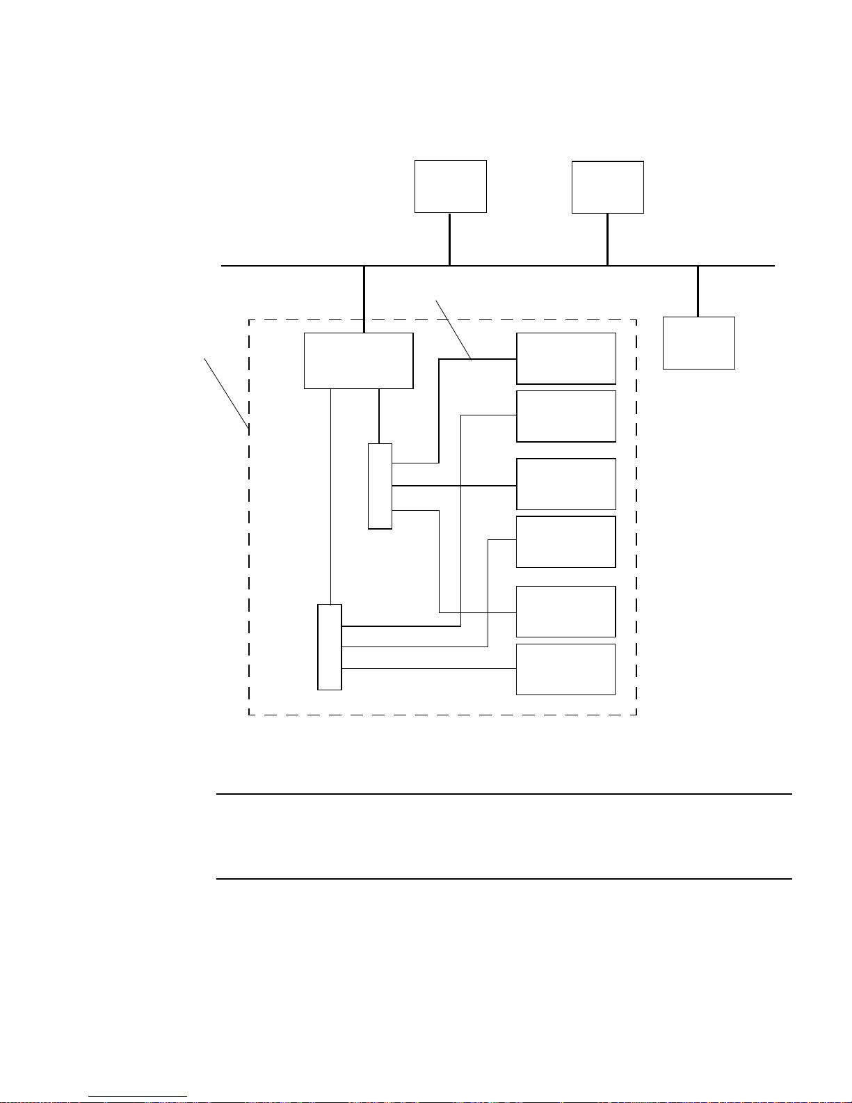
FIGURE 2 illustrates how the filer can interact in a common network environment.
6 Sun StorEdge N8400 Filer Installation, Configuration, and Service Guide • August 2001
Page 7
Network
Microsoft
Windows
host
Fibre channel
UNIX
host
N8400 filer
Sun Enterprise
420R Server
H
u
b
H
u
b
Alternate
master
T3 array
Master
T3 array
Alternate
master
T3 array
Master
T3 array
Alternate
master
T3 array
Master
T3 array
Linux
host
FIGURE 2 Sun StorEdge N8400 Filer System Example
Note – The N8400 filer system storage can be expanded in 1.0-Tbyte increments to a
maximum of 4 Tbytes. This is done by adding Sun StorEdge T3 Array partner
groups for a maximum of 8 individual arrays. Contact your local Sun sales
representative for more information.
Sun StorEdge N8400 Filer Installation, Configuration, and Service Guide 7
Page 8

Starting Up the System
Note – The order in which the machines are powered on is very important.
▼ To Startup the First Time
1. Refer to Sun StorEdge N8400 Filer Hardware Setup.
2. Proceed to “Initial Filer Setup” on page 10.
▼ To Startup After a Facility Power Failure
1. When the facility power returns, wait for every Sun StorEdge T3 Array to fully
boot.
Wait approximately eight minutes. If possible, verify that the flashing LEDs on the
back panel of the arrays go steady to indicate they are ready.
Note – The Sun Enterprise 420R Server will not be powered on when facility power
returns until the power button on the front of the unit is pushed.
2. Power on the Sun Enterprise 420R Server power button.
The boot process will take three to ten minutes, depending on the components
installed.
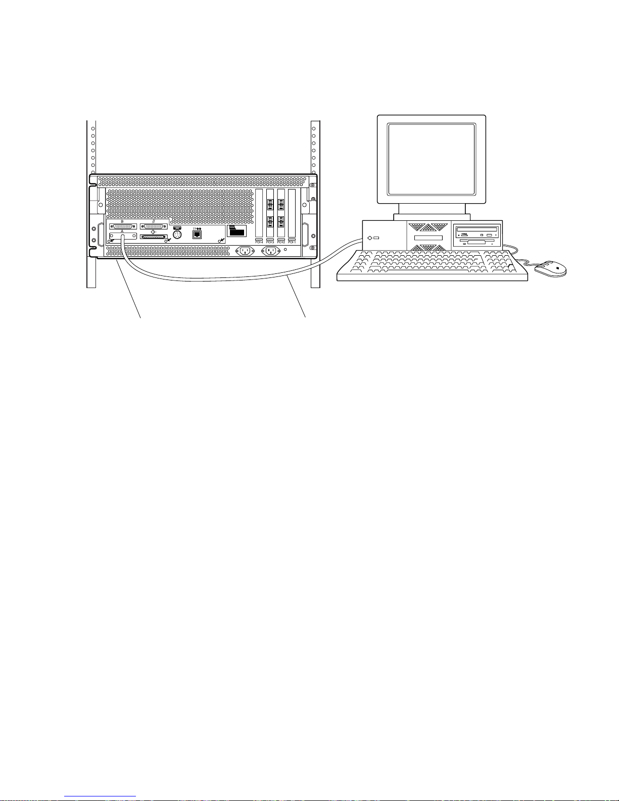
3. Connect a console to the Sun Enterprise 420R Server as shown in FIGURE 3.
8 Sun StorEdge N8400 Filer Installation, Configuration, and Service Guide • August 2001
Page 9
Console
Sun Enterprise 420R Server
FIGURE 3 Console Connection to Reboot the System
RS-232 serial cable
4. Establish communications with the filer.
See Step 1 on page 10 through Step 2 on page 13.
5. Type reboot.
Sun StorEdge N8400 Filer Installation, Configuration, and Service Guide 9
Page 10

Initial Filer Setup
This section includes instructions for configuring the filer hardware. To set up the
filer hardware, see Sun StorEdge N8400 Filer Hardware Setup. The filer hardware
includes at least one partner group of Sun StorEdge T3 Arrays (hereafter referred to
as “arrays”), the Sun Enterprise 420R Server, and the Sun expansion cabinet. This
section contains the following topics:
■ “To Set Up the Initial System Configuration” on page 10
■ “To Configure for PC Network Connectivity” on page 15
■ “To Verify the Installation” on page 16
▼ To Set Up the Initial System Configuration
This section describes how to set up and configure the filer to communicate with the
network hosts. Before starting this procedure you must be connected to the filer with
a console as shown in
Note – Before you start this procedure, review Step 4 to obtain the required
information. See your network administrator.
FIGURE 3.
1. Establish communications with the Sun Enterprise 420R Server from your console
by doing one of the following:
a. For Sun and other UNIX systems, type:
# tip -9600 /dev/ttyx
where x =aorb
Go to Step 2 on page 13.
b. For systems using Microsoft Windows™ 95, 98, or NT:
i. Choose: Start → Run.
The Run dialog box is displayed.
10 Sun StorEdge N8400 Filer Installation, Configuration, and Service Guide • August 2001
Page 11
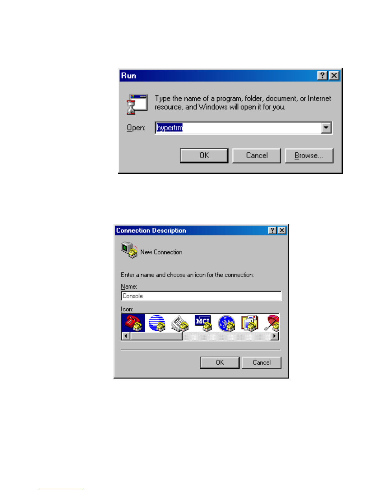
ii. Type Hypertm, and click OK.
The Connection Description dialog box is displayed.
Sun StorEdge N8400 Filer Installation, Configuration, and Service Guide 11
Page 12
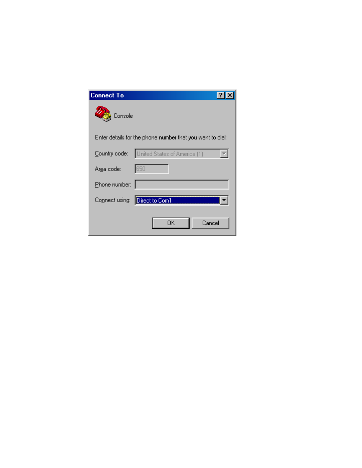
iii. Enter a connection name, choose a connection icon, and click OK.
The Connect To dialog box is displayed.
12 Sun StorEdge N8400 Filer Installation, Configuration, and Service Guide • August 2001
Page 13
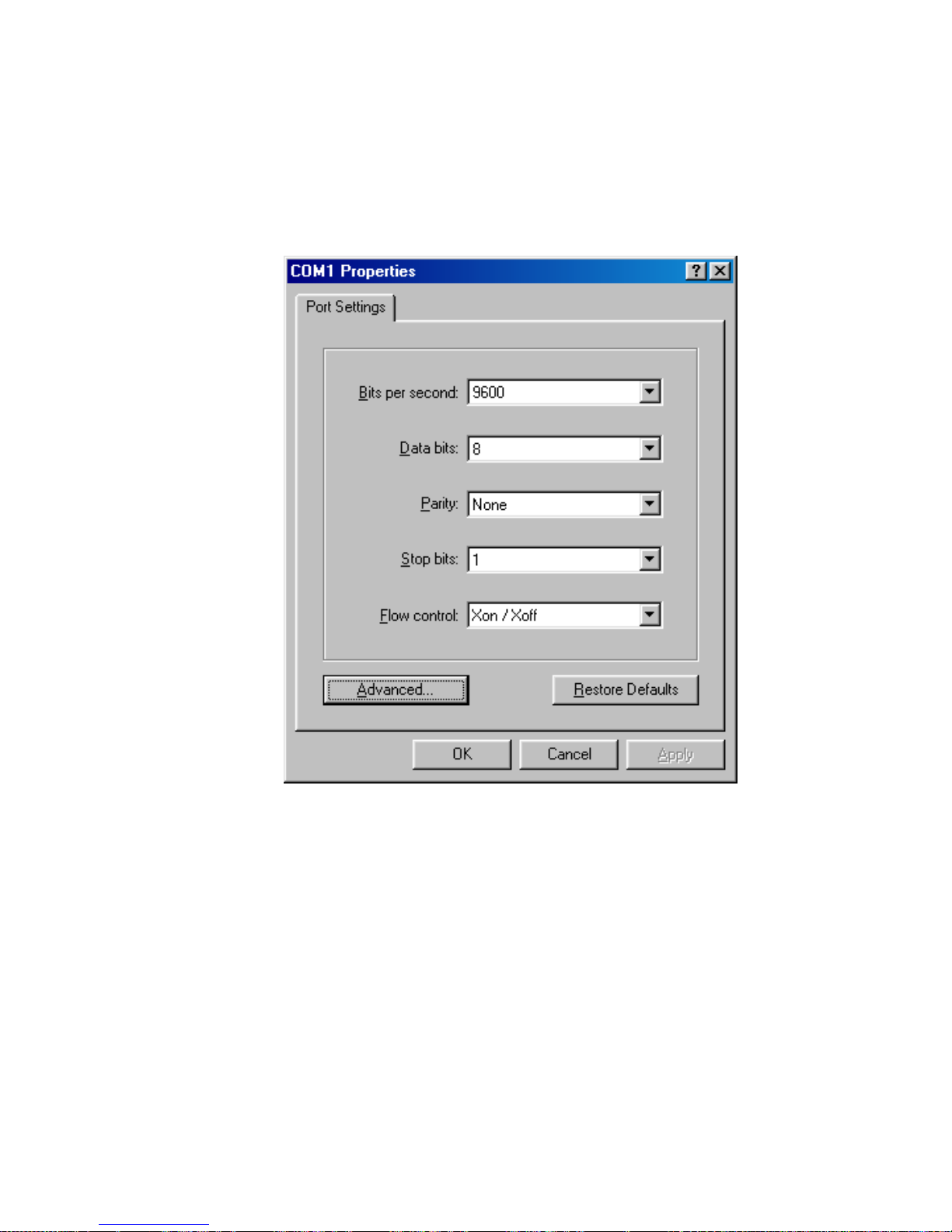
iv. Choose the COM port that will be used to connect to the filer, and then click
on OK.
The COM1 (or COM2) Properties dialog box is displayed.
FIGURE 4 Microsoft Windows COM1 Properties Dialog Box
v. Choose the exact parameters shown in FIGURE 4, and then click OK.
A new window is displayed.
2. Press Enter to obtain the ok prompt.
3. Type
boot.
The initial configuration begins.
Sun StorEdge N8400 Filer Installation, Configuration, and Service Guide 13
Page 14

Note – Before you start Step 4, review the step to identify the required information
to obtain from your network administrator.
4. Provide the following information as the system prompts you to set up the initial
configuration.
a. Choose a language. [0 = English] 0
b. Choose a locale. [0 = English] 0
c. Choose a terminal type.
[3 = DEC VT100, 12 = XTERM] 3 or 12
d. Do you have network connectivity. [Yes/No] F2 (Yes)
e. Is DHCP used? [Yes/No] No
f. Select the primary network interface. [hmeo, qfe0, etc.] hme0
g. Type the host name. _______________________, F2
h. Type the IP address. _______________________, F2
i. Is IPv6 used? [Yes/No] No
j. Confirm the above information. [Yes/No] F2 (Yes)
k. Is Kerberos security used? [Yes/No] No
l. Confirm the above information. [Yes/No] F2 (Yes)
m. Name the service. [NIS, DNS, or none] _______________________, F2
If NIS or DNS, consult your network
administrator to provide:
■ The domain name _______________________, F2
■ The domain server IP address _______________________, F2
n. Confirm the name service information. [Yes/No] F2 (Yes)
o. Is the system part of a subnet? [Yes/No] F2 (Yes)
p. Type the netmask. _______________________, F2
q. Confirm the time.
■ Region _______________________, F2
■ Time zone _______________________, F2
■ Date and time _______________________, F2
■ Confirm information _______________________, F2
14 Sun StorEdge N8400 Filer Installation, Configuration, and Service Guide • August 2001
Page 15
r. Type and verify the root password. ____________________, Enter
Note – Make a copy of these settings and store it in a safe place for future reference
and disaster recovery.
5. Wait while the system automatically reboots.
When the login prompt appears, indicating the system has successfully booted,
disconnect the serial cable from the Sun Enterprise 420R Server serial port A and the
console.
▼ To Configure for PC Network Connectivity
If the filer is connected to a network using the Windows Internet Naming Service
(WINS), perform the following steps.
Caution – Perform this procedure before accessing the administration graphical
user interface (GUI). If this procedure is used after the administration GUI has been
accessed, the procedure may generate error messages that can only be addressed by
a Sun Service Engineer.
1. Log on as the “root” user with the password assigned during the initial
configuration step r above.
2. Stop CIFS services by typing:
# /etc/int.d/ms_srv stop
3. Stop NetBIOS services by typing:
# /etc/int.d/netbios stop
4. Create a lmhosts file by typing:
# /opt/SUNWlznb/sbin/winsconf -p WINS server name
Sun StorEdge N8400 Filer Installation, Configuration, and Service Guide 15
Page 16
5. Start the NetBIOS driver by typing:
# /etc/int.d/netbios start
6. Run the joindomain command, type:
# /opt/lanman/sbin/joindomain
7. Follow the prompts and answer the questions regarding:
■ Administrative account name
■ Administrative password
■ Server name
■ Windows domain name
This completes the PC network connectivity.
▼ To Verify the Installation
Verifying the installation consists of creating a new share and accessing it from a
remote host. To complete this section, refer to the Sun StorEdge N8400 and N8600 Filer
Administrator’s Guide to perform the following steps:
Caution – Step 1 is mandatory. If you fail to perform this step you will NOT BE
ABLE TO CREATE SHARES via the administration GUI and complete the
installation verification.
1. Before using the web-based Filer Administration Tool to create Shares, you must
create one or more logical volumes.
Logical Volumes are created with the vol command using the command line
interface (CLI) as described in Chapter 4 of the Sun StorEdge N8400 and N8600 Filer
Administrator’s Guide.
2. Start the Filer Administration Tool.
Refer to “To Start the Filer Administration Tool.”
3. Create a new share.
Refer to “To Add a New Share.”
16 Sun StorEdge N8400 Filer Installation, Configuration, and Service Guide • August 2001
Page 17

4. Mount the newly created share from another host using both the NFS and CIFS
protocols.
The filer is now installed and ready to run. For instructions on how to use and
manage the filer, refer to Sun StorEdge N8400 and N8600 Filer Administrator ’s Guide .
Setting Up the Management LAN to
Monitor the Arrays
Arrays are configured in partner groups consisting of a Master Controller Unit
(MCU) and an alternate MCU. The MCU is always located below the alternate MCU
in a partner group. The MCU Ethernet connections are used to monitor and
administer the alternate MCU.
If the MCU fails and the communication between it and the alternate MCU stops, a
controller failover takes place and the alternate MCU now assumes the role of the
MCU. The new failover MCU takes the IP address and the MAC address from the
former MCU and begins to function as the administrator of the partner group. It will
also be able to access the former MCU’s drives which are still used to store syslog
information, system configuration information, and the bootcode.
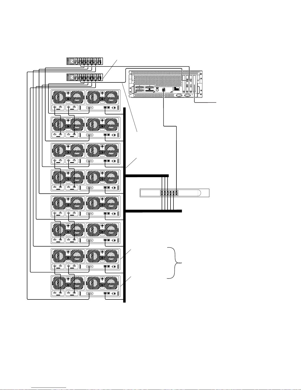
The filer can notify users of array component failures by sending email across a LAN
that is hereafter referred to as the “management LAN” (see
FIGURE 5). This is not to
be confused with the data network. The array component failures that can be
reported are:
■ Disk drives
■ Power supplies
■ Cooling units
■ Batteries
■ Controller
The arrays should be connected to the management LAN as shown in
FIGURE 5.You
are free to select any of a number of hubs available on the open market to serve as
the management LAN hub.
This section contains the following topics:
■ “To Set Up the Partner Group to Communicate with the Management LAN” on
page 19
■ “To Configure the Arrays for Monitoring” on page 22
Sun StorEdge N8400 Filer Installation, Configuration, and Service Guide 17
Page 18
MCU hub
Alternate MCU hub
Data
network
Management
LAN
Customers can
install their
choice of
interfacecards in
PCI slot 1 to
provide
communications
with a companywide LAN
Customer-supplied
management LAN hub
FIGURE 5 Sun StorEdge N8400 Filer Management LAN and Data Network
Configuration
18 Sun StorEdge N8400 Filer Installation, Configuration, and Service Guide • August 2001
Alternate MCU
Partner group
MCU
Page 19
▼ To Set Up the Partner Group to Communicate
with the Management LAN
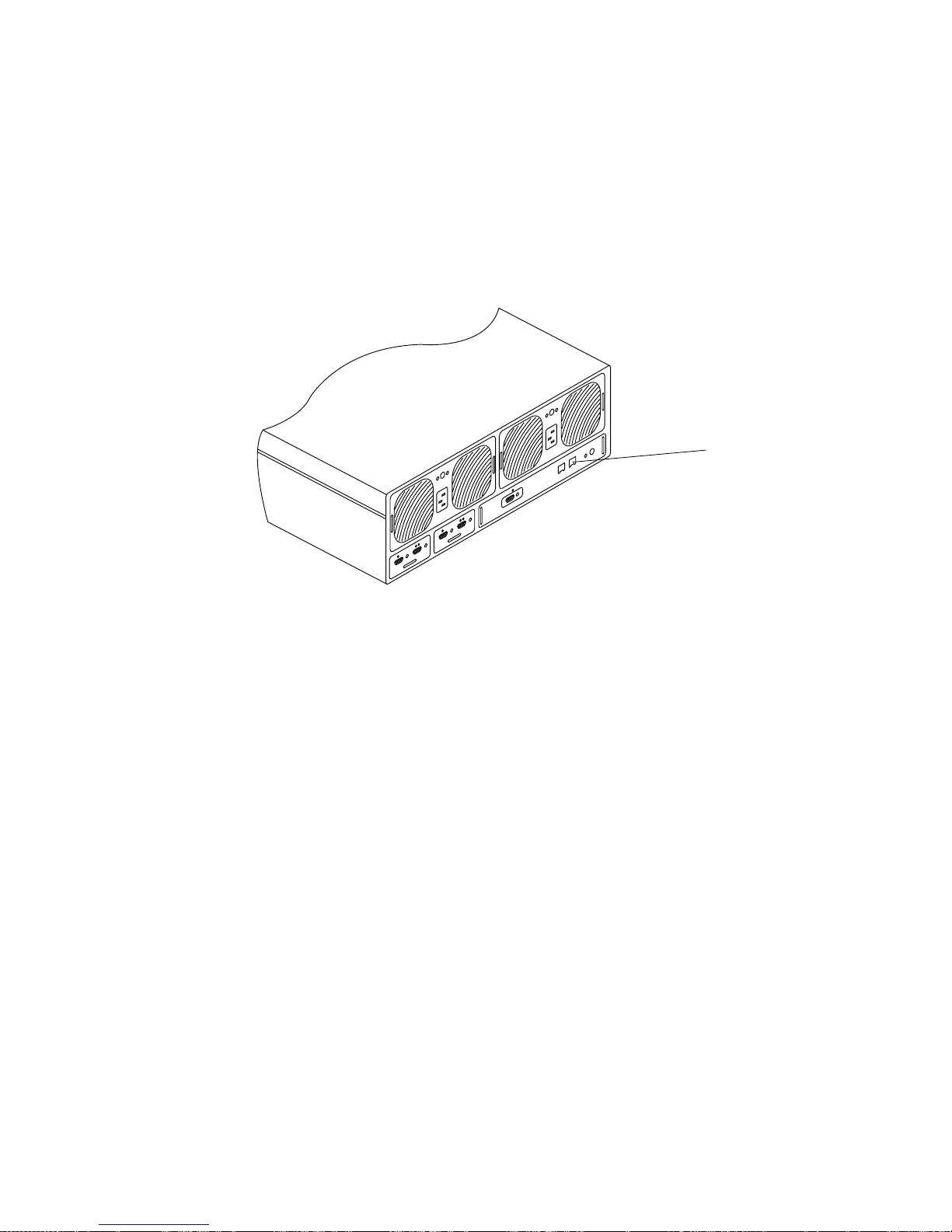
1. Connect a console to the RS-232 serial port (see FIGURE 6) on the back of a Master
Controller Unit (MCU).
RS-232 serial port
(COM)
10BASE-T Ethernet
management host
interface port (RJ-45)
MIA
FIGURE 6 Sun StorEdge T3 Array Back Panel
If you use this connection, you can proceed to Step 2 on page 20. As an alternative
you can connect to the MCU using either of the following methods:
Controller card
Tip Server
Connect to the array RS-232 serial port with your tip server. From a separate
workstation, open a telnet session to the tip server and select the corresponding port
number that represents the array. Proceed to Step 2 on page 20.
Laptop Computer
Connect a standard telephone line with an RJ-3 connector to the array RS-232 serial
port. Attach the other end to the appropriate adapter and connect that to the serial
port of your laptop PC. Set up a hyperterm connection by performing the following
steps.
a. Choose: Start → Run.
The Run dialog box is displayed.
Sun StorEdge N8400 Filer Installation, Configuration, and Service Guide 19
Page 20
b. Type hypertm, and click OK.
The Connection Description dialog box is displayed.
c. Enter a connection name, choose a connection icon, and click OK.
The Connect To dialog box is displayed.
d. Choose the COM port that will be used to connect to the filer, and then click on
OK.
The COM1 (or COM2) Properties dialog box is displayed.
e. Choose the following parameters in the COM1 Properties dialog box:
Bits per second: 9600
Data bits: 8
Parity: None
Stop bits: 1
Flow control: Xon/Xoff
Then click OK. A new window is displayed.
f. Press Enter to bring up the array command-line interface (CLI), or the login
dialogue box to access the array CLI.
If the login dialogue box appears, enter the username and password.
2. Set up the IP Address using the set ip command.
This enables the basic ethernet connectivity to the arrays. For example:
# t300name:/:<n> set ip 129.150.47.86
Note – <n> = the system-generated command count for each individual session.
3. Set up the gateway address using the set gateway command.
This enables you to access an array outside of the subnet. For example:
# t300name:/:<n> set gateway 129.150.47.1
20 Sun StorEdge N8400 Filer Installation, Configuration, and Service Guide • August 2001
Page 21
4. Set the netmask using the set netmask command.
The netmask specifies to network mask used to implement IP subnetting. For
example:
# t300name:/:<n> set netmask 255.255.255.0
This establishes connectivity for the arrays.
5. Reboot the array by typing the following:
# t300name:/:<n> sync
# t300name:/:<n> reset
Reset the system, are you sure? [N]: Y
6. Repeat “To Set Up the Partner Group to Communicate with the Management
LAN” on page 19 by connecting to the MCU of each remaining partner group.
This completes the management LAN setup.
Sun StorEdge N8400 Filer Installation, Configuration, and Service Guide 21
Page 22
▼ To Configure the Arrays for Monitoring
The arrays can now communicate across the management LAN. You must now add
the Sun Enterprise 420R Server IP address into the syslog.conf file of both the
MCU and the alternate MCU of each partner group.
▼ To Transfer the Array syslog.conf File to the Server
1. To enable an ftp connection to the array, set the root password using the passwd
command.
T300name:/:<n> passwd
OLD password: [old] password
NEW password: [new] password
NEW password (confirm): [new] password
2. Start an ftp session from the server to the array.
For example:
# ftp 192.148.226.11
Connected to 192.148.226.11.
220 server-name FTP server (SunOS 5.8) ready.
Name (192.148.226.11:root):
3. Log on to the array by typing
Name (192.148.226.11:root): root
331 Password required for root.
Password: password
230 User root logged in.
ftp>
root and then your password at the prompts.
4. Access the /etc array directory using the cd command.
ftp> cd /etc
250 CWD command successful.
ftp>
22 Sun StorEdge N8400 Filer Installation, Configuration, and Service Guide • August 2001
Page 23
5. Access your working directory on the server using the lcd command.
ftp> lcd /tmp
Local directory now/tmp
ftp>
6. Type
binary to set the transfer mode.
7. Copy the syslog.conf file from the /etc directory on the array to your working
directory using the
ftp> get syslog.conf
200 PORT command successful.
150 ASCII data connection for syslog.conf (192.148.226.11.34511)
226 ASCII transfer complete.
local: syslog.conf remote: syslog.conf
20 bytes received in 0.0021 seconds (94.81 Kbytes/s)
ftp>
get command.
8. Exit the ftp session using the bye command.
ftp> bye
221 Goodbye.
#
▼ To Edit the Array /etc/syslog.conf File
Edit the /etc/syslog.conf file to allow system messages to be forwarded to the
appropriate log files on the server. Provide the IP address of the server similar to the
following example.
Caution – Use tabs to separate field entries when editing the /etc/syslog.conf
file. If tabs are not used, any edits will not be recognized by the array.
*.info @192.148.226.11
where 192.148.226.11 is the IP address assigned to the server during its initial
configuration.
This allows for Info, Notice, Warning, and Error messages to be passed from the
array to the server.
Sun StorEdge N8400 Filer Installation, Configuration, and Service Guide 23
Page 24
▼ To Transfer the /etc/syslog.conf File Back to the Array
1. Start an ftp session from the server to the array.
For example:
# ftp 192.148.226.2
Connected to 192.148.226.2
220 server-name FTP server (SunOS 5.8) ready.
Name (192.148.226.2:root):
2. Log on to the array by typing
Name (192.148.226.2:root): root
331 Password required for root.
Password: password
230 User root logged in.
ftp>
root and then your password at the prompts.
3. Access the /etc array directory using the cd command.
ftp> cd /etc
250 CWD command successful.
ftp>
4. Access your working directory on the server where the newly created
syslog.conf file exists using the lcd command.
ftp> lcd /tmp
Local directory now/tmp
ftp>
5. Type
24 Sun StorEdge N8400 Filer Installation, Configuration, and Service Guide • August 2001
binary to set the transfer mode.
Page 25
6. Copy the syslog.conf file from your working directory to the /etc directory on
the array using the
ftp> put syslog.conf
200 PORT command successful.
150 ASCII data connection for syslog.conf (192.148.226.11.34511)
226 ASCII transfer complete.
local: syslog.conf remote: syslog.conf
20 bytes received in 0.0021 seconds (94.81 Kbytes/s)
ftp>
put command.
7. Exit the ftp session using the bye command.
ftp> bye
221 Goodbye.
#
8. Access the array by either a telnet session or a serial connection.
9. Reboot the array by typing the following:
t300:/etc:<n> sync
t300:/etc:<n> reset
Reset the system, are you sure? [N]: Y
10. Repeat “To Configure the Arrays for Monitoring” on page 22 for both arrays of
each remaining partner group.
This completes setting up the arrays for monitoring.
Sun StorEdge N8400 Filer Installation, Configuration, and Service Guide 25
Page 26

Configuration and Monitoring Options
Configuration of some of the filer’s features require specific knowledge of the
environment in which it will be operating. As such, various configuration steps must
be completed to enable these features.
There are two primary configuration options for setting up the filer on the network.
You can increase the sensitivity of the system to detecting component failures and
upgrade the backup client support. This section contains the following topics:
■ “Monitoring the Sun Enterprise 420R Server” on page 26
■ “Configuring the System to Monitor the Arrays” on page 26
■ “Backup Client Support” on page 29
■ “To Enable the Sun Solstice Backup Software” on page 29
■ “To Install the VERITAS NetBackup Software” on page 29
Monitoring the Sun Enterprise 420R Server
Monitoring the Sun Enterprise 420R Server requires system-specific agents that are
not part of the filer package. These agents are available as part of:
■ Sun Domain Manager (formerly known as SunNet Manager™)
■ Sun Management Center (formerly known as SyMon)
Configuring the System to Monitor the Arrays
You can monitor the arrays remotely by using any of the following tools that are
supplied with the filer:
■ Simple Network Management Protocol (SNMP) notification
■ Syslog error reporting
■ Array command-line interface (CLI) via a telnet session
Note – Do not confuse the array CLI with the filer CLI. The filer CLI is used to
access a simplified set of commands to manage the system.
You can also monitor the arrays remotely by using any of the following tools.
Contact your local Sun sales representative for implementation support.
■ Sun Management Center (SunMC)
■ Sun Remote Services (SRS)
26 Sun StorEdge N8400 Filer Installation, Configuration, and Service Guide • August 2001
Page 27

SNMP Notification
SNMP notification directs the software to send remote notification of array events to
the administrator’s host by using SNMP traps. An SNMP trap is a user datagram
protocol (UDP, a protocol that converts data messages generated by the system into
data packets) that is sent to a set of hosts that are identified by their IP addresses.
The contents of the trap message include header information that identifies the type
of trap and the data associated with the trap message.
When an event occurs in the array that requires attention, a trap is asynchronously
sent to the administrator’s host to report the event. The host(s) to which the trap is
sent is configured by the user. The host software that receives the trap is an SNMP
management package.
The arrays use the /etc/syslog.conf file to trigger the SNMP trap. This file
contains four levels of error warning for the administrator ’s attention. Refer to Sun
StorEdge T3 Array Administrator’s Guide for instructions on how to set up SNMP
notification.
An SNMP Management Information Base (MIB, the variables stored by an SNMP
agent) file is provided with the array for use with SNMP-based applications. The
MIB file is located in the following array directory:
/web/snmp/t300.mib
To use this file, copy the MIB file from the array to your SNMP management host
and refer to your specific SNMP management documentation for the correct MIB file
installation procedures.
Syslog Error Reporting
A syslog daemon is a background utility function that is activated to report specified
system conditions. The hardware RAID controller contains a syslog daemon that
reports system messages and provides for remote monitoring. There are four
possible levels of system messages.
■ Error. Indicates a critical system event that requires immediate user attention. An
example would be an over-temperature condition.
■ Warning. Indicates a system event that will eventually require user attention. An
example would be a disabled FRU with a recovery procedure being executed.
■ Notice. Indicates a system event that might be a side effect of other events or
possibly a normal condition. An example would be a power switch in the off
position.
■ Information. Indicates a system event that has no effect on the health of the
system. An example would be the reporting of the healthy state of a FRU.
Sun StorEdge N8400 Filer Installation, Configuration, and Service Guide 27
Page 28

You can configure syslog error reporting to consist of any combination of the levels
of messages. Refer to Sun StorEdge T3 Array Administrator’s Guide for instructions on
how to configure syslog error reporting.
Array Command-Line Interface (CLI)
The array CLI is a telnet session to the arrays, usually as “root,” and using the
arrays’ unique commands for configuration settings and troubleshooting. Examples
of these commands are: vol, sys, and fru (these commands have different
functions than those of the filer CLI). You can use the array CLI to configure the
arrays for:
■ Remote system logging
■ SNMP notification
Refer to Sun StorEdge T3 Array Administrator’s Guide.
Note – Do not confuse the array CLI with the filer CLI. The filer CLI is used to
access a simplified set of commands to manage the system.
Sun Management Center (SunMC)
To configure the system to be able to monitor the arrays with the use of SunMC,
refer to http://www.sun.com/symon.
Sun Remote Services (SRS)
To configure the system to be able to monitor the arrays with the use of SRS, refer to
http://www.sun.com/srs.
28 Sun StorEdge N8400 Filer Installation, Configuration, and Service Guide • August 2001
Page 29
Backup Client Support
The filer supports two backup products by default:
■ Sun Solstice Backup™ software
■ VERITAS NetBackup™ software
▼ To Enable the Sun Solstice Backup Software
1. Establish a telnet connection to the filer.
■ On a PC, choose Start → Run, and type telnet hostname.
■ On Solaris systems, type telnet hostname in the terminal window.
Where hostname is the host name of the filer.
The log in prompt appears.
2. Type
root.
3. Type the root password.
4. Type:
# /opt/SUNWsfadm/scripts/backup_cfg.sh
5. Answer the questions and follow the instructions.
▼ To Install the VERITAS NetBackup Software
● Follow the instructions in the VERITAS NetBackup System Administrator’s Guide,
“Adding Clients” section, to download and configure the client software.
Sun StorEdge N8400 Filer Installation, Configuration, and Service Guide 29
Page 30

Installation Troubleshooting
This section provides information and troubleshooting procedures to help resolve
problems that might occur during the installation. For additional troubleshooting,
contact your Sun service provider. This section contains the following topics:
Note – To access all the filer command-line interface (CLI) commands required for
troubleshooting, you must be logged in as the root user.
■ “Explanation of Array Hot Spare Operation” on page 30
■ “Troubleshooting System Problems” on page 31
■ “No Indication of a Console Connection Is Provided” on page 31
■ “Cannot Ping the Filer on the Network” on page 32
■ “Cannot Ping the Array on the Network” on page 33
■ “The Web Browser Displays the Message: The requested item could not
be loaded by the proxy” on page 34
■ “Troubleshooting Array Problems” on page 34
■ “A Disk Drive Fails” on page 34
■ “You Cannot Access Data on an Array and its Controller Card LED Blinks
Amber” on page 37
Explanation of Array Hot Spare Operation
A hot spare is an extra data disk used in the event of a failure of one of the data
disks in an array. If a data disk in an array fails, the unit enters a degraded mode
until all of the data on the failed disk is re-created on the hot spare. This process
typically takes between one and two hours. The hot spare disk in the array is in the
right-most drive slot (disk 9) if you look at the array from the front.
If a data disk fails, the hot spare becomes active. If the active hot spare fails, the
failure can be reported in four ways:
■ A host-generated message, found in the /var/adm/messages file, indicates a
problem with the host-channel connection to the array or a drive failure in the
array. Syslog error reports might also be generated.
■ A telnet session that monitors the array for its status
■ An Simple Network Management Protocol (SNMP) trap message is sent
■ A visual indication of a data disk failure by a slow-blinking amber LED on the
front of the array above an individual disk drive
30 Sun StorEdge N8400 Filer Installation, Configuration, and Service Guide • August 2001
Page 31
If an inactive hot spare fails, the only way to detect the failure is to issue a
healthchk command from the console.
The procedure for replacing a hot spare is identical to the procedure for replacing a
data disk. Refer to “A Disk Drive Fails” on page 34.
Troubleshooting System Problems
No Indication of a Console Connection Is Provided
The ok prompt is not displayed and there is no output.
1. Ensure that you are using the correct cables.
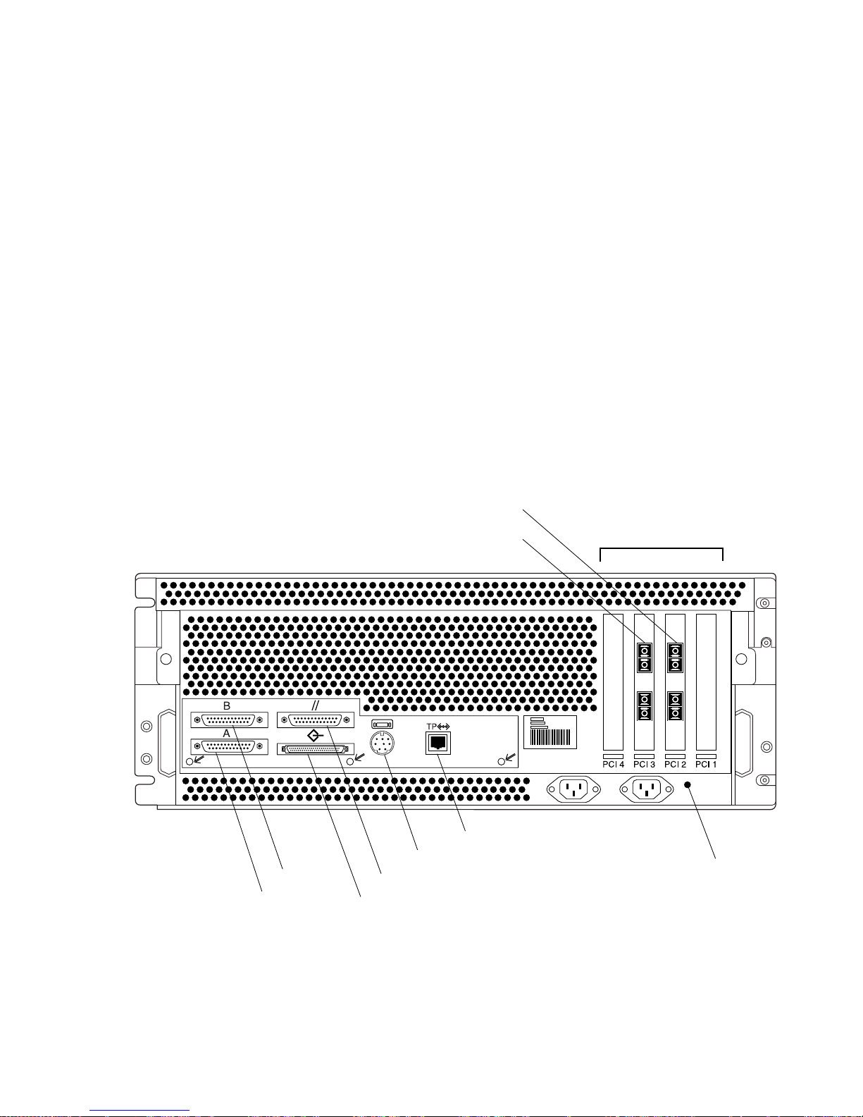
Are you using the NULL modem cable that comes with the filer in the serial port A
(see
FIGURE 7) on the back of the Sun Enterprise 420R Server?
Serial B
Serial A
Parallel
SCSI
FC-AL port 1
FC-AL port 3
TPE Ethernet (RJ-45)
Keyboard/Mouse
PCI slots 1 - 4
3
4
2
System ground
1
FIGURE 7 Sun Enterprise 420R Server Rear Panel Details and Connections
Sun StorEdge N8400 Filer Installation, Configuration, and Service Guide 31
Page 32
2. Check Step 4 on page 14 again for the proper system configuration settings.
Cannot Ping the Filer on the Network
1. Check to make sure you can ping other hosts on the network.
2. Verify the filer network cable is properly connected.
3. Check the network with the console connection.
a. Connect the serial cable to the filer.
b. Log in as a root user.
If no login prompt is displayed, go to “No Indication of a Console Connection Is
Provided” on page 31.
c. Try to ping another host on the network.
If you can ping another host, a problem exists with the network. Contact the
system administrator.
d. Check to see if the filer can see traffic on the network by typing:
# snoop -d interface
Where
interface is the name of the network interface device being used. Some
examples are hme0, hme1, qfe0, qfe1, ge0, and ge2.
If nothing is displayed on the screen, verify again that the cable connections are
correct.
Note – No indicated traffic means that the interface is not connected to the network.
e. Type:
# ifconfig -a
The output should look something like the following.
lo0: flags=849<UP,LOOPBACK.RUNNING, MULTICAST>mtu 8232
inet 127.0.0.1 netmask ff000000
hme0:flags=863<UP,BROADCAST,NOTRAILERS,RUNNING,MULTICAST>
mtu 1500 inet 192.1.1.1 netmask ffffff00 broadcast 192.1.1.255
32 Sun StorEdge N8400 Filer Installation, Configuration, and Service Guide • August 2001
Page 33
f. Verify that the following settings are correct:
■ IP address
■ Broadcast address
■ Flags
g. If any setting is incorrect, perform the following steps:
i. Type:
# vi /etc/hosts
ii. Search the file to locate the filer IP address, which should be immediately
below the local host IP address.
127.0.7.1 localhost name
192.130.151.22 filername loghost name
iii. Correct the filername IP address.
iv. Reboot by typing:
# init 6
The broadcast address and interface flags are automatically corrected.
4. If the problem persists, contact your local Sun service provider.
Cannot Ping the Array on the Network
1. Check to make sure you can ping other hosts on the network.
2. Verify that you have set the correct array hostname and IP address.
Check to ensure that the hostname or IP address is located in the /etc/hosts file.
3. Check the integrity of the cable connections.
4. If the problem persists, contact your local Sun service provider.
Sun StorEdge N8400 Filer Installation, Configuration, and Service Guide 33
Page 34
The Web Browser Displays the Message: The requested
item could not be loaded by the proxy
1. Make sure that the URL address requested is correct and complete
(IP address:port).
2. Verify that the web server software is running by establishing a telnet connection
to the filer from another host and typing:
# ps -ef|grep httpd
An output similar to the following should be displayed.
# nobody 4298 4296 0 Apr 24 ? 0:00 /usr/apache/bin/http
# nobody 4306 4296 0 Apr 24 ? 0:00 /usr/apache/bin/http
# root 4296 1 0 Apr 24 ? 0:00 /usr/apache/bin/http
# nobody 4302 4296 0 Apr 24 ? 0:00 /usr/apache/bin/http
# nobody 4301 4296 0 Apr 24 ? 0:00 /usr/apache/bin/http
# nobody 4300 4296 0 Apr 24 ? 0:00 /usr/apache/bin/http
# nobody 4299 4296 0 Apr 24 ? 0:00 /usr/apache/bin/http
■ If the http processes are not displayed, contact your local Sun service provider.
■ If the http processes are displayed and the problem persists, carefully verify the
URL address again.
Troubleshooting Array Problems
A Disk Drive Fails
This failure can be reported in the following ways:
■ A host-generated message, found in the /var/adm/messages file, indicates a
problem with the host-channel connection to the array or a drive failure in the
array. Syslog error reports might also be generated.
■ A telnet session that monitors the array for its status
■ A Simple Network Management Protocol (SNMP) trap message is sent
■ A visual indication of a data disk failure by a slow-blinking amber LED on the
front of the array above an individual disk drive
34 Sun StorEdge N8400 Filer Installation, Configuration, and Service Guide • August 2001
Page 35
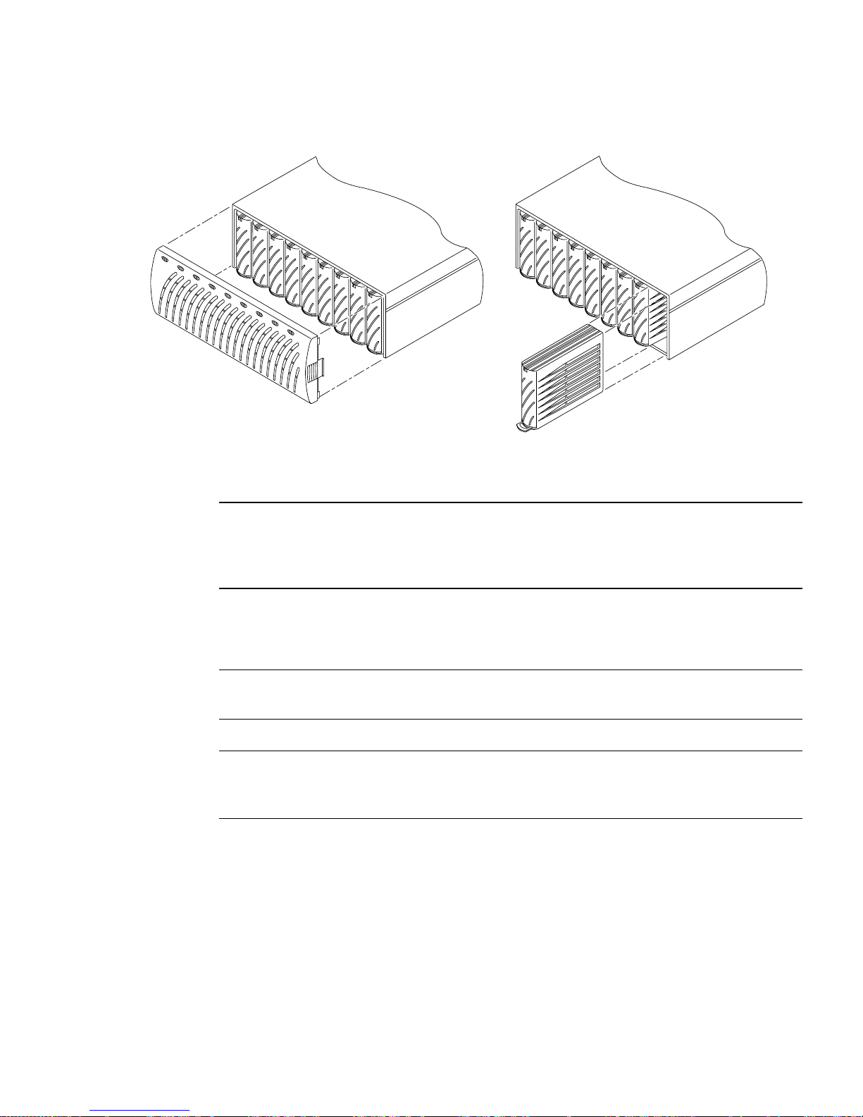
FIGURE 8 Removing an Array Front Panel and a Disk Drive
Note – When a slow-blinking amber LED indicates a drive failure, always verify the
field replaceable unit (FRU) status using the array command-line interface (CLI)
before replacing the drive. Do not confuse the array CLI with the filer CLI. The filer
CLI is used to access a simplified set of commands to manage the system.
● Replace the disk drive by following the instructions in Sun StorEdge T3 Array
Installation, Operation, and Service Manual.
Note – Upon removing a disk drive from a powered-on array, you will have 30
minutes to install a new drive, or the array will automatically power-off.
Note – Replace only one disk drive in a array at a time to ensure that no data is lost.
Complete any volume reconstructions and ensure that the disk drive is fully
functional before replacing another disk drive in the same array.
The default configuration of the arrays is to automatically spin up and re-enable a
replaced disk drive, then automatically reconstruct the data from the parity or hot
spare disk drives. Disk drive spinup takes about 30 seconds. Reconstruction of the
data on the disk drive can take up to one hour, depending on system activity.
Sun StorEdge N8400 Filer Installation, Configuration, and Service Guide 35
Page 36
Note – In some cases, if a disk drive is removed and replaced on a powered-off or
incompletely booted array, the internal system monitoring facilities may not
correctly detect the drive replacement. Therefore, always replace disk drives on
powered-on, fully booted arrays only.
For more information refer to:
■ Sun StorEdge T3 Array Installation, Operations, and Service Manual
■ Sun StorEdge T3 Array Administrator’s Guide
▼ To Verify Drive Reconstruction
To check the status of a drive and verify the reconstruction of the data, choose one of
the two following methods:
■ Visual. When you place the new drive into the array, the following sequence
should take place:
■ Disk drive amber LED blinks fast. Disk is spinning up.
■ Disk drive green and amber LEDs blink fast. Disk is being initialized.
■ Disk drive green LED blinks fast and amber LED is steady. Disk is being
reconstructed.
■ Disk drive green LED is steady. Done.
■ Telnet. Start a telnet session to the array and use the proc list command via
the array’s command-line interface (CLI).
t300:/:<35> proc list
Note – Do not confuse the array CLI with the filer CLI. The filer CLI is used to
access a simplified set of commands to manage the system.
An output similar to the following should be displayed.
VOLUME CMD_REF PERCENT TIME COMMAND
v1 20241 23 0.09 vol recon
36 Sun StorEdge N8400 Filer Installation, Configuration, and Service Guide • August 2001
Page 37
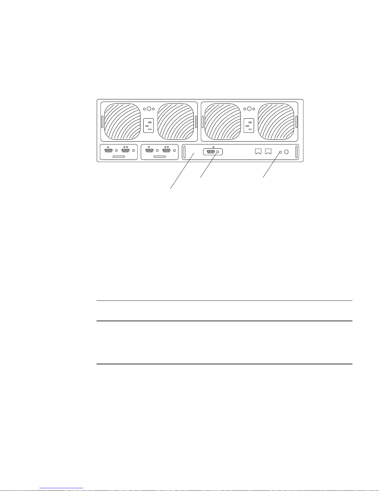
You Cannot Access Data on an Array and its Controller Card
LED Blinks Amber
Channel-active LED
Array controller card
FIGURE 9 Sun StorEdge T3 Array Controller Card Details
Array controller card
status LED
This can be due to two possible causes:
■ The fiber-optic cable of the Sun StorEdge N8400 Filer is loose.
■ The array controller card has failed. The controller card status LED blinks amber.
If this happens, the data on the disks is still intact, but you must replace the
controller card. See
TABLE 1 and TABLE 2 for an explanation of the controller card
LEDs.
TABLE 1 Channel-Active LED Descriptions
Channel Active LED
(green) Description
Off • Port disabled
Solid • Port enabled, idle
Blinking • Port enabled, activity
Sun StorEdge N8400 Filer Installation, Configuration, and Service Guide 37
Page 38
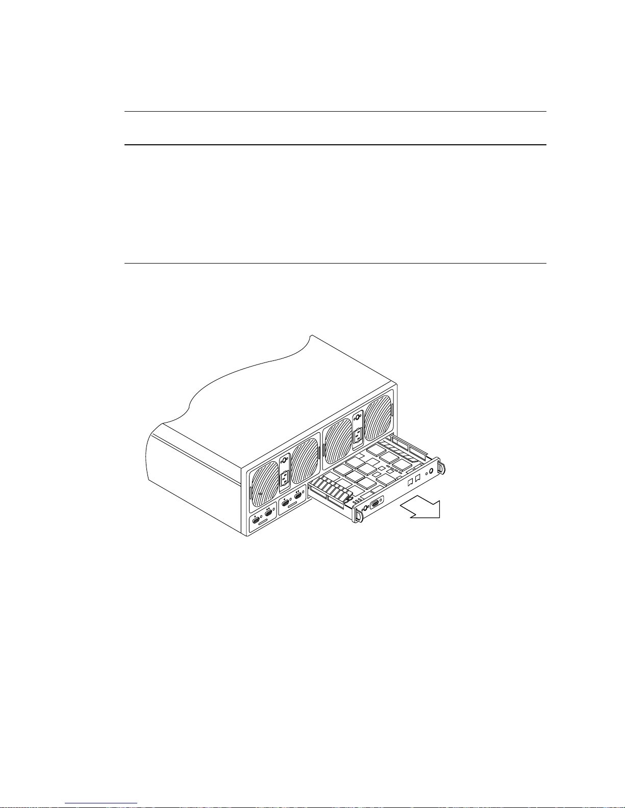
TABLE 2 Controller Status LED Descriptions
Controller Status LED
(green or amber) Description
Off • Controller not installed (not recognized)
Green • Controller OK
Amber • Controller boot/shutdown/firmware download in progress
Blinking amber • Controller failure; OK to replace controller
Note—Verify a controller card failure using the array CLI.
● If the controller card is at fault, replace it using the instructions in Sun StorEdge T3
Array Installation, Operation, and Service Manual.
FIGURE 10 Removing the Sun StorEdge T3 Array Controller Card
You do not have to reconfigure the new controller.
38 Sun StorEdge N8400 Filer Installation, Configuration, and Service Guide • August 2001
 Loading...