

Page 1

Sun S torEdge™ 6920 System
Getting St arted Guide
Installing and Configuring the System
Sun Microsystems, Inc.
www.sun.com
Part No. 817-5227-10
May 2004, Revision 01
Submit comments about this document at: http://www.sun.com/hwdocs/feedback
Page 2

Copyright 2004 Sun Microsystems, Inc., 4150 Network Circle, Santa Clara, California 95054, U.S.A. All rights reserved.
Sun Microsystems, Inc. has intellectual property rights relating to technology that is described in this document. In particular, and without
limitation, these intellectual property rights may include one or more of the U.S. patents listed at http://www.sun.com/patents and one or
more additional patents or pending patent applications in the U.S. and in other countries.
This document and the product to which it pertains are distributed under licenses restricting their use, copying, distribution, and
decompilation. No part of the product or of this document may be reproduced in any form by any means without prior written authorization of
Sun and its licensors, if any.
Third-party software, including font technology , is copyrighted and licensed from Sun suppliers.
Parts of the product may be der ived from Berkeley BSD sys tems, licensed from the U niversity of California. U NIX is a registered trademark in
the U.S. and in other countries, exclusively licensed thr ough X/Open Company, Ltd.
Sun, Sun Microsyst ems, the Sun lo go, AnswerBook2, do cs.sun.com, Sol aris, and Sun StorEdge ar e trademarks or r egister ed trademarks of Sun
Microsystems, Inc. in the U.S. and in other countries.
All SP ARC trademarks are used under license and are trademarks or registered trademarks of SP ARC International, Inc. in the U.S. and in other
countrie s. Pro ducts bear ing SPAR C tradema rks ar e based upo n an arch itectu re devel oped by Sun Microsy stems, Inc.
The OPEN LOOK and Sun™ Graphical User Interface was developed by Sun Microsystems, Inc. for its users and licensees. Sun acknowledges
the pioneering efforts of Xerox in researching and developing the concept of visual or graphical user interfaces for the computer industry . Sun
holds a non-exclusive license from Xer ox to the Xerox Gr aphical User Interface, which l icense also covers Sun’s licensees who implement OPEN
LOOK BUIs and otherwise comply with Sun’s written license agreements.
U.S. Government Rights—Commercial u se. Government users ar e subject to the Sun Microsystems, Inc. standard licens e agreement and
applicable provisions of the FAR and its supplements.
DOCUMENTATION IS PROVIDED "AS IS" AND ALL EXPRESS OR IMPLIED CONDITIONS, REPRESENTATIONS AND WARRANTIES,
INCLUDING ANY IMPLIED WARRANTY OF MERCHANTABILITY, FITNESS FOR A PARTICULAR PURPOSE OR NON-INFRINGEMENT ,
ARE DISCLAIMED, EXCEPT TO THE EXTENT THAT SUCH DISCLAIMERS ARE HELD TO BE LEGALLY INVALID.
Copyright 2004 Sun Microsystems, Inc., 4150 Network Circle, Santa Clara, California 95054, Etats-Unis. T ous droits réservés.
Sun Microsystems, Inc. a les droits de propriété intellectuels relatants à la technologie qui est décrit dans ce document. En particulier, et sans la
limitation, ces droits de propriété intellectuels peuven t inclure un ou plus des brevets américains énumérés à http://www .sun.com/patents et
un ou les brevets plus supplémentaires ou l es applications de brevet en attente dans les Etats-Unis et dans les autres pays.
Ce produit ou document est protégé par un copyright et distribué avec des licences qui en restreignent l’utilisation, la copie, la distributi on, et la
décompilation. Aucune partie de ce produit ou document ne peut être reproduite sous aucune forme, par quelque moyen que ce soit, sans
l’autorisation préalable et écrite de Sun et de ses bailleurs de licence, s’il y en a.
Le logiciel détenu par des tiers , et qui compren d la technologie r elative aux polices de c aractères, e st protégé par u n copyright et lic encié pa r des
fournisseurs de Sun.
Des parties de ce produit pourr ont êtr e dérivées des systèmes Berkeley BSD licenciés par l’ Université de Californie. UNIX est une marque
déposée aux Etats-Unis et dans d’autres pays et licenci ée exclusivement par X/Open Company, Ltd.
Sun, Sun Mic rosy stems, l e logo Sun , AnswerB ook2, docs.sun. com, et S olaris sont de s mar ques de fabriqu e ou des ma rque s dépos ées de S un
Microsystems, Inc. aux Etats-Unis et dans d’autres pays.
T oute s les mar ques S P ARC sont ut ilisé es sous l icence et sont des marq ues de f abrique ou des marques déposée s de SPA RC Intern ational, Inc.
aux Etats-Unis et dans d’autres pays. Les produits protant les marques SPARC sont basés sur une architecture développée par Sun
Microsystems, Inc.
L’interface d’utilisation graphique OPEN LOOK et Sun™ a été développée par Sun Microsystems, Inc. pour ses utilisateurs et licenciés. Sun
reconnaît les efforts de pionniers de Xerox pour la recherche et le développement du concept des interfaces d’utilisation visuelle ou graphiq ue
pour l’industrie de l’informatique. Sun détient une license non exclusive de Xerox sur l’interface d’utilisation graphique Xerox, cette licence
couvrant également les licenciées de Sun qui mettent en place l’interface d ’utilisation graphique OPEN LOOK et qui en outre se conforment aux
licences écrites de Sun.
LA DOCUMENTATION EST FOURNIE "EN L’ÉTAT" ET TOUTES AUTRES CONDITIONS, DECLARATIONS ET GARANTIES EXPRESSES
OU TACITES SONT FORMELLEMENT EXCLUES, DANS LA MESURE AUTORISEE PAR LA LOI APPLICABLE, Y COMPRIS NOT AMMENT
TOUTE GARANTIE IMPLICITE RELATIVE A LA QUALITE MARCHANDE, A L’APTITUDE A UNE UTILISATION PARTICULIERE OU A
L’ABSENCE DE CONTREFAÇON.
Please
Recycle
Page 3

Contents
Preface xiii
1. System Overview 1
Hardware Overview 2
Storage Array Configurations 5
Internal and Ex ter nal Netw or ks 6
Software Ove rv iew 7
User Interf ac e s 7
Resident Software 8
Required Host Software 8
Solaris Host Software 8
Host Software fo r Oth er Op era ti ng S yst ems 9
Additional Supported Software 10
Supported Third-Party Software 10
2. Installing the System 11
Before You Begin 12
Installing the System Cabinet 13
Required Tools 13
Moving and Positioning the Base Cabinet 13
Contents iii
Page 4

Stabilizing the Base Cabinet 14
Adjusting the Leveling Pads and Installing the Stabilizer Legs 14
Adjusting the Leveling Pads 1 5
Installing the Stabilizer Legs 15
Installing the Floor-Mounting Brackets 17
Connecting an Exp ansion Cabinet 19
Connecting the Fibre Channel Cables 19
Connecting the Ethernet Cables of the Expans ion Cabin et 21
Powering On the System 22
Required Tools 22
Connect in g th e Grou nd i ng Cable of th e B ase C ab in e t 22
Connecti n g th e Po w er C ab le s 24
Powering On the System 27
Installing the USB Flash Disk 28
Setting Up the Remote Response Service 29
Connecting Data Hosts 30
Connecting Hosts to a SAN 32
Connecting Hosts Directly 33
Selecting Ports for Additional Host Connections 33
Selecting Ports for Additional Storage Connections 34
Troubleshooting Tips 34
3. Configur in g th e S ys te m 37
Before You Begin 38
Running the Initial Configuration Script 3 8
Establishing the Serial Connection 38
Running the Initial Configuration Script 3 9
Logging In and Navigating the System Using the GUI 45
About User Accounts 46
iv Sun StorEdge 6920 System Getting Started Guide • May 2004
Page 5

Logging In to the System 46
Navigating the System 49
About the GU I La you t 49
Getting Help 52
Completing the Initial Configuration 53
Configuring General Settings 5 3
Setting Site Informa t ion for Diagnostics and Monitoring 54
Setting the Expansion Cabinet Array Addre sses 56
Provisioning Storage 57
About Sto rage Elements 57
What Is a Storage Domain? 59
What Is a Storage Profile? 60
What Is a Volume? 61
What Is a Storage Pool? 61
What Is a Virtual Disk? 62
What Is a Snapshot? 63
About the Default Configuration 65
Storage Allocation Considerations 65
Provisioning Storage Using the Default Configuration 66
Viewing the Default Configuration Settings 6 6
Creating Volumes 67
Common Storage Configuratio n Tasks 69
Creating a Stor age Pool 70
Adding Storage to a Poo l 70
Creating a Storage Domain 71
Creating a Storage Profile 71
Contents v
Page 6

A. Remote Response Service 75
Supported Country Listing 75
Remote Response Service Worksheet 76
Connecting Multiple Systems 77
B. Remote and Local Power Management 79
Preparing the System for Remote Power 80
Connect ing the Grounding Cabl e 83
Connecti n g th e Po w er C ab le s 84
Powering On the System 87
Enabling Support for Remote Power Management 90
Performing a Partial System Shutdown 91
Performing a Full Sys tem Shutd ow n 93
Restoring Power to the System 96
Restoring Power to the System Af ter a Partial System Shutdown 96
Restoring Power to the System After a Full System Shutdown 97
Troubleshooting Tips 99
C. Product Specifications 101
Physical Character istics 101
Physical Specifications 102
Power Sequencer Electrical Specifications 103
Environmental Requirements 104
D. Packing Lists 105
Accessory Kit Packing List 105
Serial Connectio n FRU Lis t 107
Power Cable FRU List 107
Expansion Cabinet FRU L ist 107
vi Sun StorEdge 6920 System Getting Started Guide • May 2004
Page 7

E. Information Collection Worksheet 109
Glossary 111
Index 119
Contents vii
Page 8

viii Sun StorEdge 6920 System Getting Started Guide • May 2004
Page 9

Figures
FIGURE 1-1 Sun StorEdge 6920 System Base Cabinet – Front and Back Views 2
FIGURE 1-2 Array Configuration Options 5
FIGURE 2-1 Leveling Pads 15
FIGURE 2-2 Stabilizer Legs 16
FIGURE 2-3 Installi ng the Right Stabili z er Leg 16
FIGURE 2-4 Adjusting the Leveling Pads on the Stabilizer Leg 17
FIGURE 2-5 Removing the Bottom Right Front Mounting Screws 18
FIGURE 2-6 Attaching the Floor-Mounting Brackets 18
FIGURE 2-7 Base Cabinet Service Panel 19
FIGURE 2-8 Expansion Cabinet Service Panel 20
FIGURE 2-9 FC Cabling Between the Base Cabinet and an Expansion Cabinet 20
FIGURE 2-10 Ethernet Cabling Between the Base Cabinet and an Expansion Cabinet 21
FIGURE 2-11 Location of the Key Switch on the Bottom Front Panel of System Cabinet 23
FIGURE 2-12 Attaching the Grounding Cable to the Front Power Sequencer 24
FIGURE 2-13 Rear Power Sequencer Control Panel 25
FIGURE 2-14 Connecting the Power Cables 26
FIGURE 2-15 Front Sequencer Status Lights 27
FIGURE 2-16 USB Flash Disk Write Protection Switch 29
FIGURE 2-17 Storage Service Processor: USB Port 1 29
FIGURE 2-18 Connecting Hosts to a SAN 32
Figures ix
Page 10

FIGURE 2-19 Connecting Host s Direc tly 33
FIGURE 3-1 Sun Web Console Login Page 47
FIGURE 3-2 Sun Web Console Page 48
FIGURE 3-3 Sun StorEdge 6920 System Graphical User Interface (GUI) 49
FIGURE 3-4 Navigating the GUI: Access Butto ns 50
FIGURE 3-5 Navigating the GUI: Quic k Statu s Disp lay 50
FIGURE 3-6 Navigating the GUI: Manag em en t Soft ware Na vi gat ion al Tab s 51
FIGURE 3-7 Navigating the GUI: Page Content and Actions 51
FIGURE 3-8 Help Button 52
FIGURE 3-9 Example: New Volume Wizard 68
x Sun StorEdge 6920 System Getting Started Guide • May 2004
Page 11

Tables
TABLE 1-1 System Hardware Components 4
TABLE 1-2 Storage Array Configuration Options 5
TABLE 1-3 Internal and External LANs 6
TABLE 1-4 Resident (Pre-installed) System Software 8
TABLE 3-1 User Accounts 46
TABLE 3-2 GUI Elements 52
TABLE 3-3 Sun StorEdge 6920 System Logical and Physical Components of the System 58
Tables xi
Page 12

xii Sun StorEdge 6920 System Getting Started Guide • May 2004
Page 13

Preface
The Sun StorEdge™ 6920 System Getting Started Guide provides procedures for
installing the Sun StorEdge™ 6920 system. This guide describes how to complete
the initial setup of the system, power the sy stem on and off, and connect the
system to the dat a hosts on the storag e area network (SAN ) and the manageme nt
console on the local area network (LAN).
Before You Read This Book
Before you begin to install the Sun StorEdge 6920 syst em, you must prepare the
installation site as described in these books:
■ Sun StorEdge 6920 Regulatory and Safety Compliance Manual
■ Sun StorEdge 6920 System Site Preparation Guide
How This Book Is Organized
Chapter 1 contains an introduction to the Sun StorEdge 6920 system.
Chapter 2 describes pre-installation planning, safety, and installation of the system
cabinet, and system startup.
Chapter 3 describes the steps you must take to establish an initial connection to the
system, run the setup utility, log in to the system, navigate the system, and use the
wizards to configure storage on the system.
Preface xiii
Page 14

Shell Prompts
Shell Prompt
C shell machine-name%
C shell superuser machine-name#
Bourne sh ell and Ko rn shell $
Bourne shell and Korn shell superuser #
Typographic Conventions
Typeface
AaBbCc123 The names of commands, files,
*
AaBbCc123
AaBbCc123 Book titles, new words or terms,
*. The settings on your browser might differ from these settings.
Meaning Examples
and directories; on-screen
computer output
What you type, when contrasted
with on-screen computer output
words to be emphasized.
Replace command-line variables
with real names or values.
Edit you r.login file.
Use ls -a to lis t all files.
% You have mail.
% su
Password:
Read Chapter 6 in the User’s Guide.
These are called class options.
You must be superuser to do this.
To delete a file, type rm filename.
xiv Sun StorEdge 6920 System Getting Started Guide • May 2004
Page 15

Sun StorEdge 6920 System
Documentation
The following is a list of documents related to the Sun StorEdge 6920 system. For
any document number with nn as a suffix, use the most current document.
Subject Title Part Number
Unpacking instructio ns
attach ed to the shipp ing
container
System license information Sun St orEdge 6920 System License Cards 817-5829-nn
System planning information Sun StorEdge 6920 System Site Preparation Guide 817-5224-nn
System regulatory and safety
information
Late-breakin g informa tion
not included in t he
information set
Instructions for software
installation from CD
Unpacking Guide 816-5230-nn
817-5225-nn
Sun StorEdge 6920 System Regulatory and S afety Compliance
Manual
Sun StorEdge 6920 System Release Notes 816-5229-nn
Sun StorEdge 6920 System Host Inst allation Software Guide 817-5831-nn
817-5230-nn
System overview information, as well as information on system configuration,
maintenance, and basic troubleshooting, is covered in the online help included with
the software. In addition, t he sscs(1M) man page provides inform ation about the
commands us ed to manage st orage using the command- line interf ace (CLI).
Preface xv
Page 16

Related Documentation
The following documents provide detailed information, if needed, about related
system componen ts.
Product Title Part Number
SAN Foundation Software Sun StorEdge SAN Foundation 4.4 Configuration Guide 817-3672-nn
Tr a f f ic M a nag e r Sof t war e Sun StorEdge Traffic Manager 4.4 Software Release Notes For HP -
UX, IBM AIX, Microsoft Windows 2000 and 2003, a nd Red Hat
Enterprise Linux
Sun StorEdge Traffic Manager 4.4 Software User ’s Guide For IBM
AIX, HP-UX, Microsoft Windows 2000 and 2003, and Red Hat
Enterprise Linux
Sun StorEdge Traffic Manager 4.4 Software Installation Guide For
Red Hat Enterprise Linux
Sun StorEdge Traffic Manager 4.4 Software Installation Guide For
Microsoft Windows 2000 and 2003
Sun StorEdge Traffic Manager 4.4 Software Installation Guide For
IBM AIX
Sun StorEdge Traffic Manager 4.4 Software Installation Guide For
HP - U X 11 . 0 a n d 11 i
Sun StorEdge network Fibre
Channel switch-8 and
switch-16
Sun StorEdge Network 2Gb FC Switch-8 and Switch-16 FRU
Installation
Sun StorEdge Network 2 Gb FC Switch-8 and Switch-16 Re lease
Notes
Sun StorEdge Network 2 Gb FC Switch-64 Release N otes 817-0977-nn
817-6275-nn
817-6270-nn
817-6271-nn
817-6272-nn
817-6273-nn
817-6274-nn
817-0064-nn
817-0770-nn
Sun StorEdge Brocade switch
documentation
Sun StorEdge McData switch
documentation
Storage Automated
Diagnostic Environment
software
Expansion cabinet Sun StorEdge Expansion Cabinet Installation and Service M anual 805-3067-nn
Storage Service Processor Sun Fire V100 Server User’s Guide 816-2756-nn
Solaris Operating System Solaris Handbook for Sun Per ipherals 816-4468-nn
xvi Sun StorEdge 6920 System Getting Started Guide • May 2004
Sun StorEdge Network 2 Gb Brocade SilkWorm 3200, 3800, and
12000 Switch 3.1/4.1 Firmware Guide to Documentat ion
Sun StorEdge Network 2 Gb M cDATA Intrepid 6064 Director
Guide to Documentation, Including Firmware 5.01.00
Storage Automated Diagnost ic Environment 2.3 Getting Started
Guide
817-0062-nn
817-0063-nn
817-3284-nn
Page 17
Related Vendor Documentation
For installation instructions and other information about Brocade and McData Fibre
Channel switches, refer to the product documentation provided by the vendor.
Accessing Sun Documentation Online
You can view, print, or purchase a broad selection of Sun documentation, including
localized versions, at:
http://www.sun.com/documentation
For Sun StorEdge 6920 syste m documentation, go to:
http://www.sun.com/products-n-solutions/hardware/docs/
Network_Storage_Solutions/Midrange/6920/index.html
Contacting Sun Technical Support
If you have tech nical questi ons about this product that are not answ ered in this
guide, go to:
http://www.sun.co m/se rvice/contacting
Sun Welcomes Your Comments
Sun is interested in improving its documentation and welcomes your comments and
suggestions. You can submit your comments by going t o:
http://www.sun.com/ hwdo cs/feedback
Please include the title and part number of this document with your feedback:
Sun StorEdge 6920 System Getting Started Guide, part number 817-5 227-10
Preface xvii
Page 18

xviii Sun StorEdge 6920 System Getting Started Guide • May 2004
Page 19

CHAPTER
1
System Overview
This chapter describes the components and terminology of the Sun StorEdge 6920
system. It includ es the following secti ons:
■ “Hardware Overview” on page 2
■ “Software Overview” on pag e 7
1
Page 20
Hardware Overview
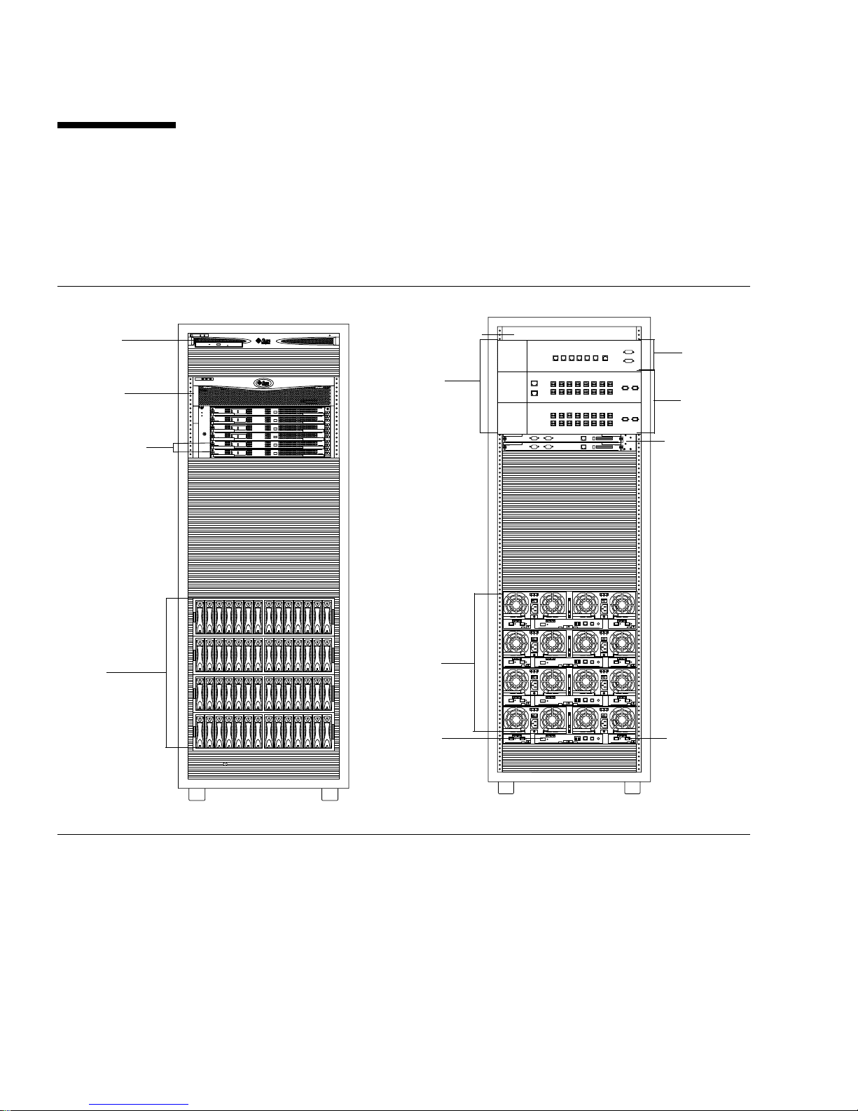
The Sun StorEdge 6920 syst em has a modular architectu re with integrated systemwide manageability. The system base cabinet contains all of the hardware
components for the system.
Storage Service
Processor
(SSP)
Data Services
Platform
(DSP)
Switch fabr ic
cards (SFCs)
Storage
arrays
SSP
accessory tray
Service
panel
Storage
arrays
SERVICE
PROCESSOR
PANEL
I/O
I/O
EXP ENET 1
EXP ENET 2
NPORT
A
B
NPORT
C
D
SERVICE
SERVICE
SP LAN
SP LANINUSER
AUX
SERIAL
CONSOLE
OUT
LAN
1
2345678
1
2345678
PWR SEQUENCER
PHONE
OUT FRONT
OUT REAR
EXP
FC2
FC1
A
EXP
FC2
FC1
B
Service
Processor
panel
I/O panels
Management
interface
cards (MICs)
Front View
FIGURE 1-1 Sun StorEdge 6920 Sy stem Base Cabin et – Front and Back Views
From the front of the system’s base cabi net, you can view the LEDs for the St orage
Service Processor, Data Services Platform (DSP), and storage arrays.
2 Sun StorEdge 6920 System Getting Started Guide • May 2004
Power
sequencer
Storage
array LEDs
Back View
Page 21

From the back of the base cabinet, you can access the service panel for cabling the
hosts, storage area network (SAN), and local area network (LAN) to the Sun
StorEdge 6920 system. You can also access storage arrays and the Data Servic es
Platform’s field replaceable units (FRUs) such as power and cooling units, array
controll ers, an d stora ge resource cards.
The system can comprise a base cabinet alone, or it can include an expansion
cabinet.
For more information about configuration options and instructions on how to
expand the syste m by adding disks, trays, cabinets, storage arrays, Fibre Channel
(FC) ports, and external FC switches, see the online help.
TABLE 1-1 describ es the Sun StorEdge 6920 syst em hardware components.
Chapter 1 System Overview 3
Page 22

TABLE 1-1 Syste m Hard ware Co mpon ents
Component Description
Service panel The service panel simplifies the cabling to the system. It provides the
following:
• Modem connection
• LAN connections for management
• Serial ports
• I/O connections for data hosts
• Power connections for expansion rack management
• Ethernet and FC connections for expansion racks
• AUX port to connect to the DSP management interface card (MIC) card,
which provides management interface failover
You connect cables to these accessible panel connections rather than to
individual components of the system.
In Chapter 2 you will learn how to connect to the panel based on your
system’s configuration.
Storage Service Processor The Storage Service Processor is a management host residing in the
system’s base cabinet. The management software arrives pre-installed on
the Storage Service Processor. The S torage Service Processor is cabled to
the service panel, allowing for easy serial and local area network (LAN)
connections. You do not connect directly to the Storage Service Processor.
Storage Service Processor
accessory tray
Data Services Platform (DSP) The DSP provides virtualization services for the storage devices in the
Storage arrays The storage arrays make up the physical storage of the Sun StorEdge 6920
Ethernet hub The Ethernet hub manages internal network traffic on the Sun StorEdge
The Storage Service Processor accessory tray provides a number of
functions for the system, including:
• Network terminal concentrator (NTC)
• Router with a firewall
• Modem to connect to the Sun StorEdge Remote Response service
system. It also provides FC switching so that the system does not require
additional switches.
system. The individual disk trays in an array can contain from seven to
fourteen disk drives each.
6920 system.
For more information about hardware components, go to the online help system.
Click the Sea rch tab and type hardware.
4 Sun StorEdge 6920 System Getting Started Guide • May 2004
Page 23
Storage Array Configurations
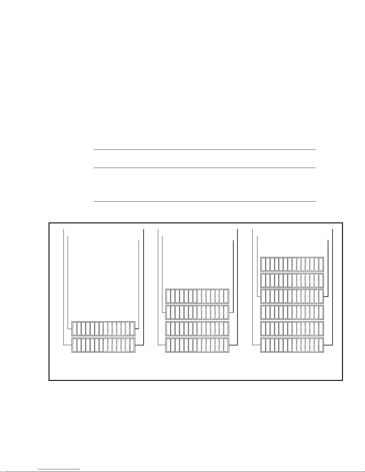
The storage array design is modular, with a variety of possible configurations
FIGURE 1-2). Each configuration option includes two controllers (also referred to as a
(
controlle r pair) t o provide red undanc y and fail over cap abilit ies. Eac h storag e array
also has redundant Fibre Channel (FC) dat a paths and two power supplies w ith an
integral battery backup system. In the event of a total power failure, each array has
sufficient power from the batteries to shut down in an orderly fashion.
The system is available in three supported storage array configurations:
TABLE 1-2 Storage Array Configuration Options
Ethernet
Ethernet
Number o f
Option Trays x Controllers
1 2 x 2 14 to 28 504 gigabytes 4 terabytes
2 2 x 4 28 to 56 1 terabyte 8 terabytes
3 2 x 6 42 to 84 1.5 terabytes 12 terabytes
2 GB FC
Ethernet
2 GB FC
Disk Drive s
Ethernet
2 GB FC
Minimum
Capacity
2 GB FC
Maximum
Capacity
Ethernet
Ethernet
2 GB FC
2 GB FC
2x2 Configu ration:
Two Controllers and
Two Storage Trays
FIGURE 1-2 Array Configurat ion Option s
2x4 Configura tion:
Two Controllers and
Four Storage Trays
2x6 Configurat ion:
Two Controllers and
Six Storage Trays
Chapter 1 System Overview 5
Page 24

The configuration of the system is based on requirements for throughput, amount of
storage, and economy. For example, if throughput is more important to you th an
economy, you might want your system to use the option 1 storage array
configuration. In cont rast, if the amount of availab le storage is more important to
you than throughpu t, you might w ant your syste m to use the opti on 2 or 3 storage
array configuration.
A controller tray contains disk drives and built-in RAID management hardware. An
expansion tray contains disk drives only and is managed by a controller tray.
FC I/O connections on the service panel connect to the controller of each array in the
base cabinet. This cabling is attached at the factory before the cabinet is shipped.
For more information about array configuration, see the online help.
Internal and External Networks
The Sun StorEdge 6920 syst em incorporates three separate networks: The Storage
Service Processor LAN, the internal component LAN, and the site (customer) LAN
(
TABLE 1-3).
TABLE 1-3 Internal and External LANs
Network Description
Storage Service Processor LAN The Storage Service Processor LAN is used by the Sun StorEdge Remote
Response system to remotely monitor the Sun StorEdge 6920 system.
When multiple Sun StorEdge 6920 systems (up to eight at the same site)
are installed, the systems can share a single telephone line.
Internal Component LAN The Storage Service Processor communicates with components that make
up the system over this LAN. This network is not accessible from outside
the system and is isolated from the data path.
Site (customer) LAN This LAN connects to the customer’s internal Ethernet LAN. This network
enables access to the system from the user’s management host. The
management host is used to configure, control, and monitor the system
through a web browser or a thin-scripting client. A firewall is included in the
router of the Storage Service Processor accessory tray between the user
LAN and the Storage Service Processor LAN.
Note – In addition to the firewall supplied with the Sun StorEdge 6920 system, you
can also use a site firewall implemented with your own corporate security policies.
However, you cannot use your own firewall in place of the firewall supplied with
the Sun StorEdge 6920 sys tem.
6 Sun StorEdge 6920 System Getting Started Guide • May 2004
Page 25

Software Ov erview
This section describes the following software used in the system:
■ “User Interfaces” on page 7
■ “Resident Software” on pag e 8
■ “Required Host Software” on page 8
User Interfaces
You can access the syste m software using the two ma in interfaces to the syst em:
■ A browser-based graphical user interface (GUI)
■ A command-line interface (CLI), available through a thin-scripting client for
remote mana gement
Note – See the Sun StorEdge 6920 System Release Notes for a list of supported
browsers.
In addition to providing the same control and monitoring capability as the web
browser, the thin-scripting client is also scriptable. If you want to configure storage
from a remote management host, you can install the thin-scripting client on an
external server and then use the sscs commands to access the system.
For more information about the thin-scripting client, see the Sun StorEdge 6920
System Host In stallatio n Guide and the sscs(1M) man page.
Chapter 1 System Overview 7
Page 26

Resident Software
TABLE 1-4 describes the software that is pre-installed on the Sun StorEdge 6920
system.
TABLE 1-4 Resident (Pre-installed) System Software
Software Description
System and storage
management
software
System monitoring
and diagnostic
software
Revision
maintenance
software
Sun StorEdge
Remote Response
software
Sun StorEdge
Storage Pool
Manager software
Sun StorEdge Data
Snapshot software
Provides configuration services through a centralized management tool.
Provides a diagnostic monitoring tool for the system. It can be configured to monitor on
a 24-hour basis, collecting information that enhances the reliability, availability, and
serviceability (RAS) of the Sun StorEdge 6920 system.
Provides a tool for upgrading firmware revisions of all components resident in the
system. It also keeps track of these firmware levels and whether components are using
the latest fi r mware revi si o n s .
Connects to the Sun Service Center, allowing trained personnel to remotely monitor,
troubleshoot, diagnose, and service the system. If the Sun Service Center organization
determines that there is a problem, Sun will recommend and perform maintenance on
the system.
Enables virtualization and pooling of storage assets across applications. Up to 2
terabytes of capacity is provided with the system. Additional right to use (RTU) licensing
is required for use of larger capacities.
Allows for the creation of point-in-time snapshot copies of a volume. The snapshot
copies can be read/write-mounted by applications to secondary storage and used for
backup, application testing, or data mining without the need to take the primary storage
offline. The right to use (RTU) license is issued per system and is based on the capacity
of primary storage that will be snapped.
Required Host Software
In addition to the software that is pre-installed on the system, there is additional
software that must be installed on hosts for t he system e ither to func tion properly or
to gain additional functionality. This software is summarized in the following
sections.
Solaris Host Software
The Host Installation CD that ships with the syst em includes a variety of Sol aris
host-based software for managing the Sun StorEdge 6920 system. You specify the
functionality you require, and the CD installs the necessary software.
8 Sun StorEdge 6920 System Getting Started Guide • May 2004
Page 27

The software on the Host Installation CD includes:
■ Sun StorEdge SAN Foundation software – Incorporates dri vers and ut ilities th at
enable Solaris data hosts to connect to, monitor, and transfer data in a SAN.
To enable multipathing functionality, each Solaris data host must have Sun
StorEdge Traffic Manager software installed before it can reliably communicate
with the system’ s storag e. You may also choose to purchase VERI TAS software, as
described in “Additional Su pported Software” on page 10, to enable Dyna mic
Multipathing (DMP).
■ Storage Automated Diagnostic Environment software, Device Edition – Resides
on a data host or management console to monitor devices in the SAN.
■ Sun StorEdge Remote Configuration CLI – Enables Solaris hosts to remotely
configure storage for the Sun StorEdge 6920 system.
Host Software for Other Operating Systems
Additional host software enab les data hosts that run operat ing systems other than
Solaris to communicate with the Sun StorEdge 6920 system. For details about the
supported operating systems and versions, see the Sun StorEdge 6920 System Release
Notes.
This software consists of the following:
■ Sun StorEdge Traffic Manager Software – Is required for hosts to make use of
the Sun StorEdge 6920 system’s storage. The Traffic Manager software
incorporates kernel drivers and utilities that enable data hosts to connect to,
monitor, and transfer data in a SAN. The Traffic Manager software is available for
Microsoft Windows 2000, Microsoft Windows 2003, Red Hat Linux, HP-UX, and
IBM AIX operating environments.
■ Sun StorEdge Remote Configuration CLI – Enables hosts to remotely configu re
storage for the Sun StorEdge 6920 system. The remote CLI software is available
for Microsoft Windows 2000, Microsoft Windows 2003, Red Hat Linux, HP-UX,
and IBM AIX operating env ironments.
You can download host software for non-Solaris operating systems from Sun’s
Download Center at :
http://wwws.sun.com/software/download/sys_admin.html
Go to the Download Center, select the Sun StorEdge 6920 system related software
link, and follow the instructions to register and download the host software.
Chapter 1 System Overview 9
Page 28

Additional Supported Software
The following host-bas ed software is supported by the Sun StorEdge 6920 syst em:
■ Sun StorEdge Enterprise Storage Manager – SAN management software that
helps you manage SAN environments, including the Sun StorEdge 6920 system,
other Sun StorEdge storage syste ms, arrays, a nd heterogeneous hosts.
■ Sun StorEdge Availability Suite – Software that provides for remote mirroring
and point-in-time copies of data.
■ Sun StorEdge Enterprise Backup Software – Software that provides backup,
recovery, and other services for a variety of operating environments.
■ Solstice DiskSuite (for the Solaris 8 Operating System) – Software that manages
data and disk drives.
■ Solaris Volume Manager (embedded in the Solaris 9 Operating System) –
Software that lets you manage large numbers of disks and the data on those disks.
■ Sun StorEdge Performance Suite with Sun StorEdge QFS – Software that
provides scalability, high performance, and reliable data integrity for applications
managing large number of files, many large files or large file systems in a
distributed network environment.
■ Sun StorEdge Utilization Suite with Sun StorEdge SAM-FS – Archive
management software that automatically copies files from online disk to archive
media.
■ Sun Cluster software – Software that extends the Solaris Operating System into a
cluster operating environment, providing support for high availability, failover,
and scalable services.
■ Sun StorEdge Diagnostic Expert – Software provides remote monitoring and
diagnostics for Sun storage devices.
Supported Third-Party Software
The Sun StorEdge 6920 system is compatible with the following third-party
applications:
■ VERITAS NetBackup Server
■ VERITAS NetBackup Enterprise Server
■ VERITA S Volume Manager with Dynamic Multipathing (DMP) for Solaris
■ VERITAS File System (VxFS) for Solaris
■ VERITAS Volume Replicator for Solaris
■ Legato NetWorker
You can purchase any of this software and install it on hosts connected to the Sun
StorEdge 6920 system. For a li st of supported releases and versions, see the Sun
StorEdge 6920 System Release Notes.
10 Sun StorEdge 6920 System Getting Started Guide • May 2004
Page 29

CHAPTER
2
Installing the System
This chapter provides complete procedures for installing the Sun StorEdge 6920
system. It includ es the following secti ons:
■ “Before You Begin” on page 12
■ “Install ing the Sy stem Cab inet” on page 13
■ “Connecting an Expansion Cabinet” on page 19
■ “Powering On the System” on page 22
■ “Installing th e USB Flash Disk” on page 28
■ “Setting Up the Remote Response Se rvice” on page 29
■ “Connecting Data Hosts” on page 30
■ ‘‘Troubleshooting Tips” on page 2-34
You can als o refer to “A t a Glanc e: Inst alling t he Syste m” on p age 35 for a high-l evel
overview of the procedures described in this chapter.
11
Page 30

Before You Begin
Before you can begin to install the system, you must complete the following steps:
1. Complete all of the installation preparation tasks described in the Sun StorEdge
6920 System Site Preparation Guide, including:
■ Configuring two separate power drops
■ Ensuring a convenient earth ground
■ Having an external telephone line available for activation of the Sun StorEdge
Remote Respons e service
Note – If you have not completed the requirements outlined in the Sun StorEdge
6920 System Site Preparation Guide, do not attempt to install the system. Your
warranty might become void if you perform an improper installation.
Note – If you do not have a copy of the Sun StorEdge 6920 System Site Preparation
Guide, you can download it from the S torEdge 6920 system docume ntation web site,
as described in the Preface of this guide.
2. Unpack the system. (See the packing instructions that are attached to the outside
of the shipping container.)
3. Verify the packing list (Appendix D) against the contents of the accessories kit.
4. Use the Information Collection Worksheet (Appendix E) to gather the information
you will need to complete the installation.
12 Sun StorEdge 6920 System Getting Started Guide • May 2004
Page 31

Installing the System C abinet
This section covers the main steps for installing the base cabinet:
■ “Moving and Positioning the Base Cabinet” on page 13
■ “Stabilizing the Base Cabinet” on page 14
Required Tools
You will need the following tools for the installation:
■ Leveling wrench (shipped with the system)
■ 7/16-inch ratchet wrench
■ 1/2-inch ratche t wrench
Moving and Positioning the Base Cabinet
You must install the Sun StorEdge 6920 system in accordance with the local safety
codes and regulations. This section contains additional safety information for the
local facility.
1. Measure cabling distances to ensure that the supplied cable is adequate.
The grounding ca ble for the c abinet is 6.5 fe et (~2 meters) long.
Refer to the product specifications in Appendix C when you are determining where
to place the cabinet.
2. Move the base cabinet into position.
Caution – A fully configured base cabinet weighs in excess of 1400 pounds (635 kg).
Ensure that all surfaces this system will move over can wi thstand this load.
Additionally, the cabinet is top heavy, even when you order the minimum
configuration. Keep this in mind when moving the system.
The base cabinet has wheels. Plan to have two to three people available to move the
cabinet into position, one to push the system off the pallet onto the ramp, and the
others to offer resistance so that the cabinet doe s not roll. Make sure there is
adequate space in front of the cabinet to ensure that it will not roll into anything.
Move the cabinet slowly and make sure the floor is free of objects and cables.
Chapter 2 Installing the System 13
Page 32
Caution – Never lift the system base cabinet by the cosmetic panel surfaces or pull
it from the back. Instead, push the middle section of the cabinet to prevent it from
tipping over. Use two or more people to move the cabinet safely: one in front to
control the movement and one behind.
3. Secure the base cabinet in position.
To minimize personnel injury in the event of a seismic occurrence, you should
securely fast en th e cab inet to a rigi d stru cture ex ten ding from th e fl oor to th e ce ilin g
or to the walls of the room in which you place the cabinet.
Install the cabinet on a level surface. There are adjustable nonskid pads at each
corner of the cabinet base. Extend these pads when the cabinet is installed to prevent
the unit from rolling. Do not use these pads to level the cabinet.
4. Ensure the base cabinet has proper ventilation.
Air cools the cabinet from front to back. Air enters at the front, circulates through the
system, and is expelled at both the top and back of the cabinet. Position the cabinet
so as to ensure proper ventilation.
Caution – Do not block or cover the openings of the cabinet, and do not place it
near a radiator or heat register.
Stabilizing the Base Cabinet
To stabilize the base cabinet, you must perform one of the following procedures:
■ Adjust the leveling pads and install the stabilizer legs
■ Install the floor-mounting brackets
Adjusting the Leveling Pads and Inst alling the Stabilizer Legs
Unless you are using the floor mounting brackets, the four leveling pads must be
lowered to the floor for the cabinet to meet Underwriters Laboratories’ physical
stability requirements.
The stabilizer legs help prevent the system from tipping over when field-replaceable
units (FRUs) are serviced in the system. The stabilizer legs must be properly
installed and set to be effective.
If you want to attach the system directly to the floor, skip to “Installing the FloorMounting Brackets” on page 17.
14 Sun StorEdge 6920 System Getting Started Guide • May 2004
Page 33
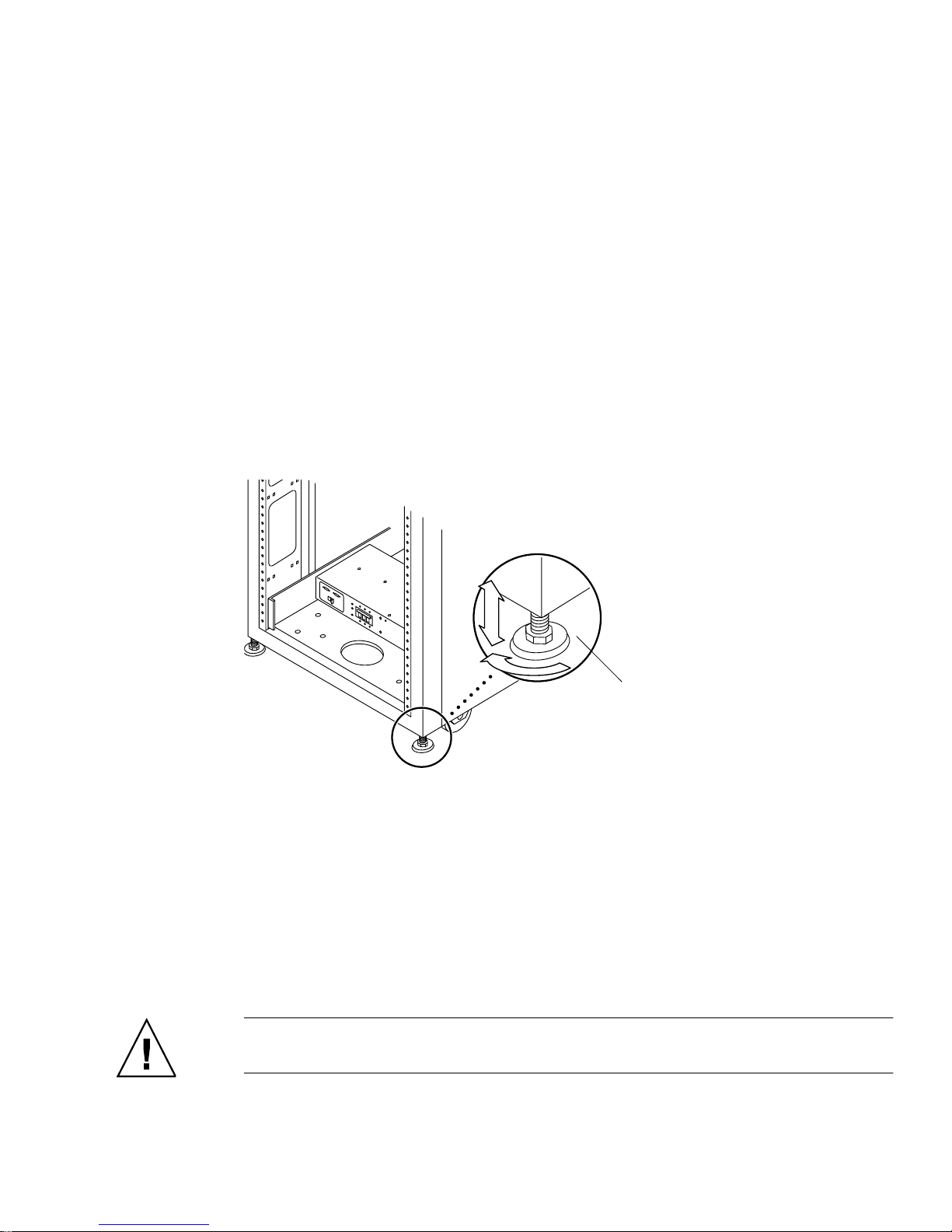
Adjusting the Leveling Pads
The leveling pads (screws) are located at each corner at the base of the cabinet
FIGURE 2-1).
(
1. Open the back door of the base cabinet.
2. Remove the leveling wrench by unlocking the plastic strap that holds it to the
inside of the frame, near the top of the cabinet.
Do not cut the st rap . P ress th e plas ti c ta b t o un lo ck the str ap arou nd th e wre nch, an d
then slide part of the strap through the lock to loosen the wrench.
3. Adjust the four leveling pads on the cabinet frame using the leveling wrench
(
FIGURE 2-1).
Ensure that the four pads press against the floor so that the cabinet does not move or
rock in a ny dire ct ion .
Leveling
pad
FIGURE 2-1 Leveling Pads
4. Replace the leveling wrench in its plastic strap and tighten the strap.
5. Continue with the next section, “Installing the Stabilizer Legs” to help prevent
the base cabinet from tipping over when f ield-replaceable units (FRUs) are
serviced.
Installing the Stabilizer Legs
Caution – Always extend the sta bilizer legs before atte mpting to i nstall new F RUs
or to service FRUs in the system.
Chapter 2 Installing the System 15
Page 34
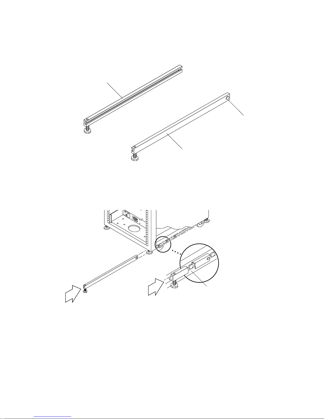
1. Loosen the securing screw on the right stabilizer le g (FIGURE 2-2).
Left stabilizer leg
Securing
screw
Right stabilizer leg
FIGURE 2-2 Stabilizer Legs
2. Slide the right stabilizer leg over the three mounting screws at the bottom of the
system cabinet (
FIGURE 2-3) and fully extend it.
FIGURE 2-3 Installing the Right Stabil izer Leg
3. Tighten the securing screw.
This prevents the stabilizer leg from falling off the mounting screws when it is
extended.
4. Repeat Step 1 through Step 3 for the left stabilizer leg.
16 Sun StorEdge 6920 System Getting Started Guide • May 2004
Mounting screws
Page 35
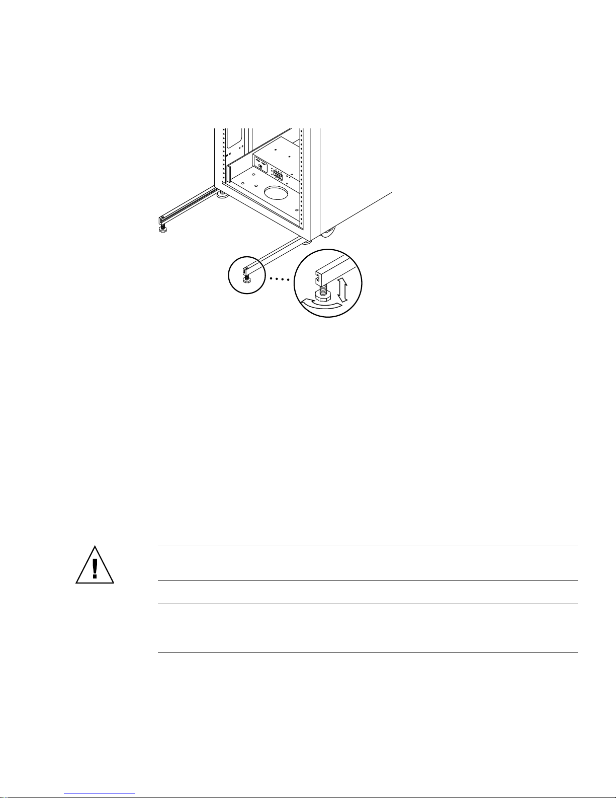
5. Use the leveling wrench to adjust the feet on both stabilizer legs so that they
touch the floor (
FIGURE 2-4 Adjusting the Leveling Pads on the Stabilizer Leg
FIGURE 2-4).
6. Slide both stabilizer legs under the system cabinet.
7. Resecure the leveling wrench inside the system cabinet.
8. Close the back door.
Installing the Floor-Mounting Brackets
Skip this section if you have installed the stabilizer legs and adjusted the leveling
pads.
Use the four floor-mounting brackets to attach the system to the floor. The bolts to
secure the floor- mounting brackets are not included.
Caution – Do not bolt the floor-mo unting bra ckets to the deck plating of a raised
(computer-room) floor, because this would result in an unstable mount.
Note – If you are installing the floor-mounting brackets over previously installed
threaded rods, loosely attach the floor-mounting brackets to the rods and then to the
system.
Chapter 2 Installing the System 17
Page 36
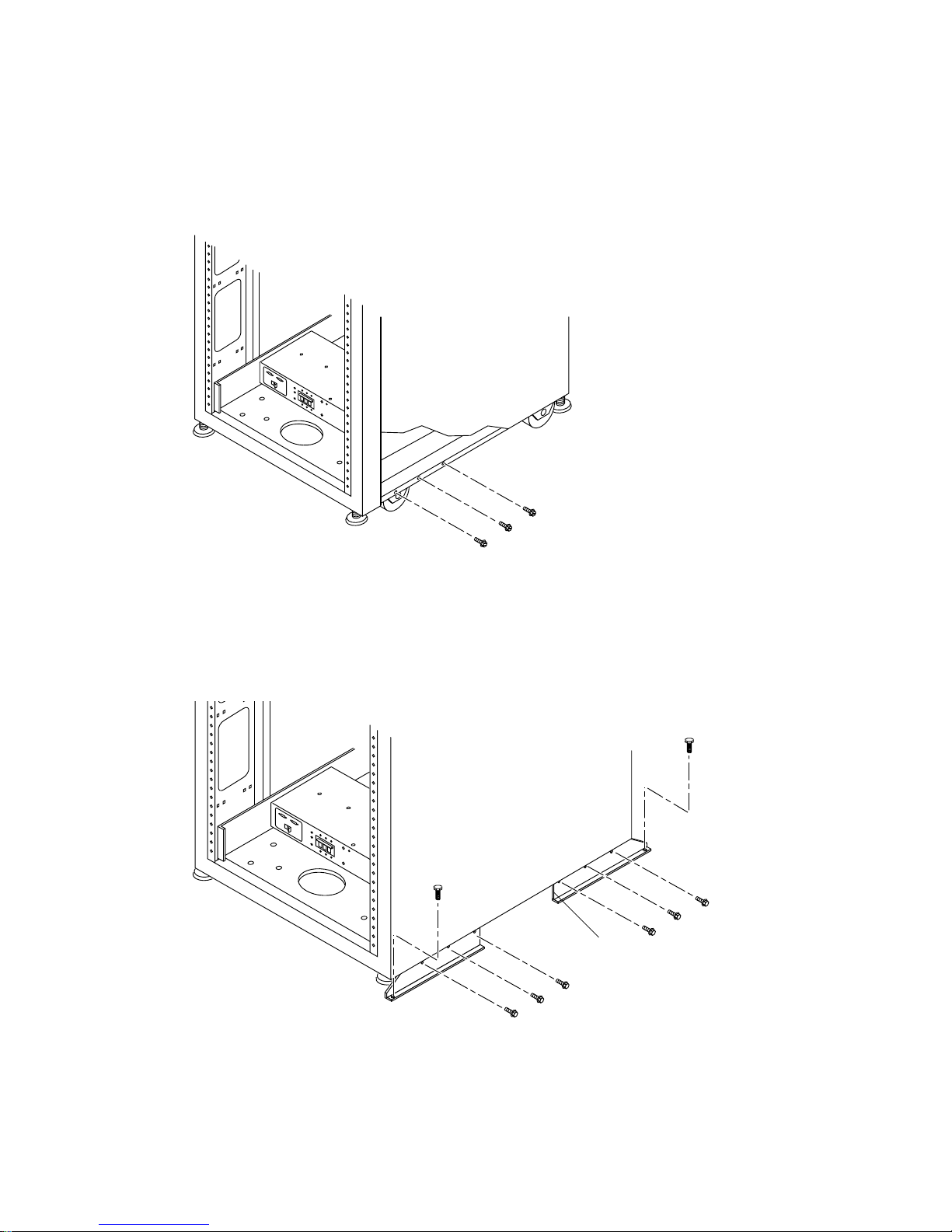
1. Remove the three mounting screws on the bottom right side of the front
FIGURE 2-5) and the three mounti ng screws on the bo ttom righ t side of the back of
(
the system.
FIGURE 2-5 Removing the Bottom Right Front Mounting Screws
2. Using a 7/16-inch r atchet wrench, attach the right floor-mounting brackets to the
front and back of the system (
FIGURE 2-6) with the six mounting screws you just
removed.
Floor-mountin g br acke ts
FIGURE 2-6 Attaching the Floor-Mounting Brackets
18 Sun StorEdge 6920 System Getting Started Guide • May 2004
Page 37
3. Bolt the right floor-mounting brackets to the floor.
4. Repeat Step 1 through Step 3 for the left floor-mounting brackets.
Connecting an Expansion Cabinet
If you purchased a Sun StorEdge 6920 system with an expansion cabinet, the
following sections describe how to connect the expansion cabinet to the base cabinet:
■ “Connecting the Fibre Channel Cables” on page 19
■ “Connecting the Ethernet Cables of the Expansion Cabinet” on page 21
■ “Ethernet Cabling Between the Base Cabinet and an Expansion Cabinet” on
page 21
Caution – You must connect the expansion cabinet before connecting power to the
base cabinet .
Connecting the Fibre Channel Cables
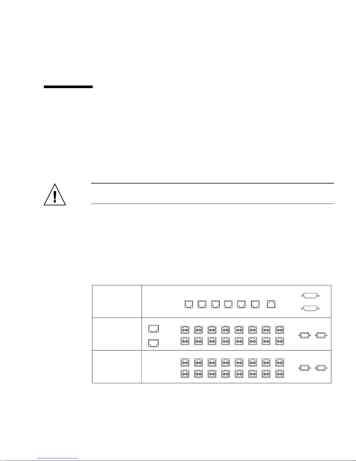
The base cabinet’s service panel has two I/O panels with redundant Fibre Channel
(FC) ports to connect to the expansion cabinet (
service panel has a single panel with redundant FC ports (
SP LAN
SERVICE
OUT
SP LANINUSER
PROCESSOR
P ANEL
1
EXP ENET 1
NPORT
2345678
A
I/O
EXP ENET 2
B
1
NPORT
2345678
C
I/O
D
FIGURE 2-7 Base Cabinet Servi ce Panel
FIGURE 2-7). The expansion cabinet’s
FIGURE 2-8).
PWR SEQUENCER
LAN
AUX
SERVICE
SERIAL
SERVICE
CONSOLE
PHONE
A
B
OUT FRONT
OUT REAR
EXP 1
FC1
EXP 2
FC1
FC2
FC2
Chapter 2 Installing the System 19
Page 38
PWR SEQUENCER
OUT FRONT IN
OUT REAR IN
EXP
EXP
AB
ENET
FIGURE 2-8 Expansion Ca binet Ser vice Panel
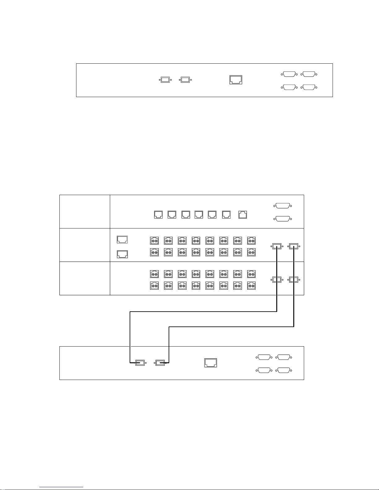
To connect an expansion cabinet, connect redundant Fibre Channel (FC) cables (part
number 537-1060-01) as follo ws (see
■ Connect port EXP1 A FC1 of the base cabine t’s upper I/O panel to port EXP A of
FIGURE 2-9):
the expansion cabinet service panel
■ Connect port EXP1 A FC2 of the base cabinet’s upper I/O panel to port EXP B of
the expansion cabinet service panel
SERVICE
PROCESSOR
P ANEL
I/O
I/O
EXP
EXP ENET 1
EXP ENET 2
SP LAN
SP LANINUSER
OUT
2345678
1
NPORT
A
B
2345678
1
NPORT
C
D
EXP
AB
LAN
AUX
SERVICE
SERIAL
ENET
SERVICE
CONSOLE
PHONE
PWR SEQUENCER
OUT FRONT
OUT REAR
EXP 1
FC1
A
EXP 2
FC1
B
PWR SEQUENCER
OUT FRONT IN
OUT REAR IN
FC2
FC2
FIGURE 2-9 FC Cabling Betwe en the Ba se Cabinet an d an Expansi on Cabinet
20 Sun StorEdge 6920 System Getting Started Guide • May 2004
Page 39
Connecting the Ethernet Cables of the Expansion
Cabinet
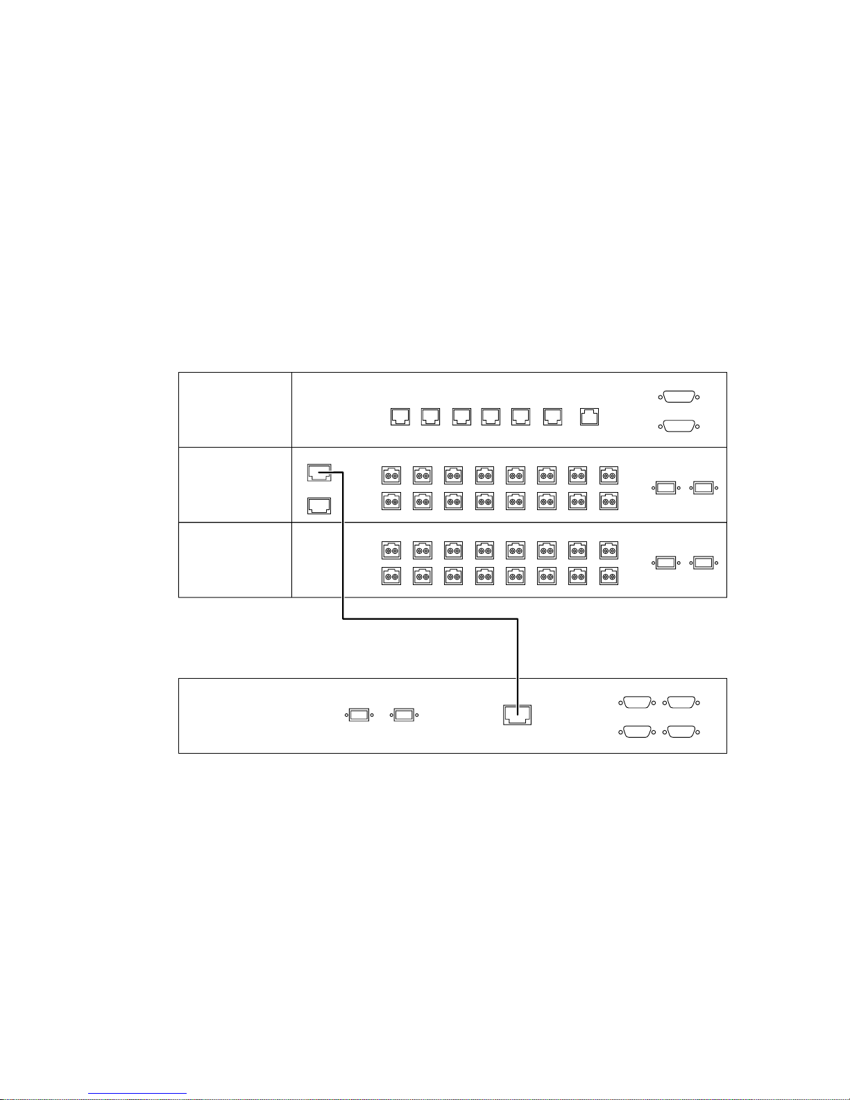
The base cabinet’s service panel has two expansion Ethernet ports for connecting an
expansion cabinet. The service panel on an expansion cabinet has a single Ethernet
port for connecting to the base cabinet.
To connect an expansion cabinet, connect an Ethernet cable (10M RJ45/RJ45
Rollover, part number 530-3138 -01) betwee n the EXP ENE T 1 port on the up per I/O
panel of the base cabinet and the ENET port on the service panel of the expansion
cabinet (
FIGURE 2-10).
SERVICE
PROCESSOR
P ANEL
I/O
I/O
EXP
EXP ENET 1
EXP ENET 2
SP LAN
SP LANINUSER
OUT
2345678
1
NPORT
A
B
2345678
1
NPORT
C
D
EXP
AB
LAN
AUX
SERVICE
SERIAL
ENET
SERVICE
CONSOLE
PHONE
PWR SEQUENCER
OUT FRONT
OUT REAR
EXP 1
FC1
A
EXP 2
FC1
B
PWR SEQUENCER
OUT FRONT IN
OUT REAR IN
FC2
FC2
FIGURE 2-10 Ethernet Cab ling Between the Base Cabi net and an Exp ansion Cabine t
If you are setting up the system to enable remote power management, you must
connect the power sequencer serial cables between the base cabinet and expansion
cabinet, as described in Step 8 of Appendix B.
Chapter 2 Installing the System 21
Page 40

Powering On the System
This section covers the procedures for cabling and powering on the system for the
first time. You must complete the following three procedures in consecutive order to
correctly power on the system.
■ “Connecting the Grounding Cable of the Base Cabinet” on page 22
■ “Connecting the Power Ca bles” on page 24
■ “Powering On the System” on page 27
Note – If you want to enable the system for lights-out management, which allows
you to perform a remote partia l system shutdo wn, go to “Prepari ng the System for
Remote Power” on page 80.
Required Tools
The followi ng tools are required to perform the ta sks in this sec tion:
■ Keys for key switch (s hipped with the sy stem)
■ Phillips screwdriver
Connecting the Grounding Cable of the Base
Cabinet
You must connect the grounding cable to either a grounding post or something
attached to a grounding post. The system is designed to work with single-phase
power systems that have a grounded neutral conductor.
1. Open the front and back doors of the system cabinet.
2. Locate the key switch at the bottom of the front panel (
FIGURE 2-11).
22 Sun StorEdge 6920 System Getting Started Guide • May 2004
Page 41
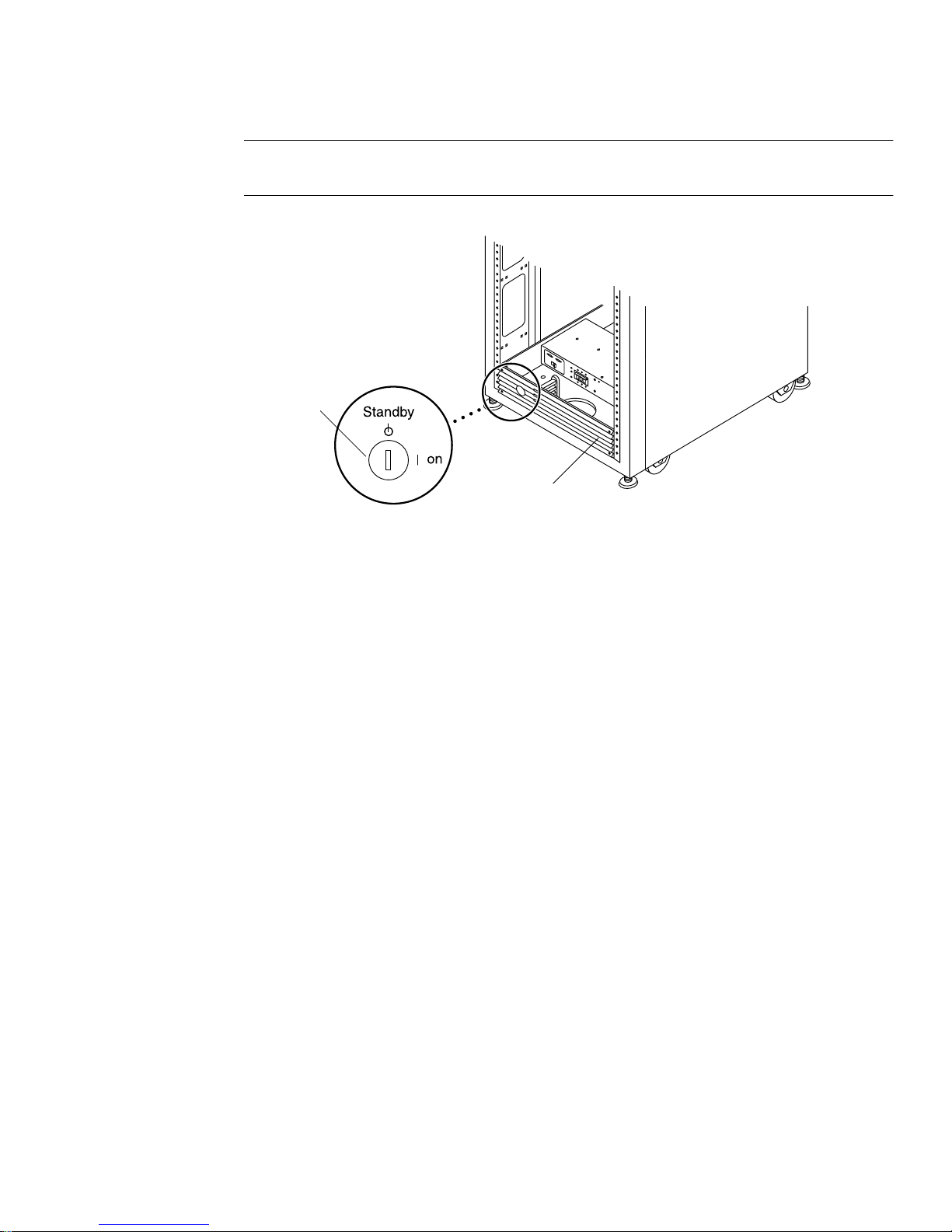
Note – The position of the key swit ch does not ma tter for local power-on and
power-off operations (FIGURE 2-11).
Key switch
Front trim panel
FIGURE 2-11 Location of the Key Switch on the Bo ttom Front Panel of Syst em Cabinet
3. Remove the front trim panel and set the panel aside.
4. Locate the 6.5-foot (~2-meter) grounding cable in the accessories kit.
5. Attach one end of the grounding cable to the front power sequencer on the cabinet
(
FIGURE 2-12).
Chapter 2 Installing the System 23
Page 42
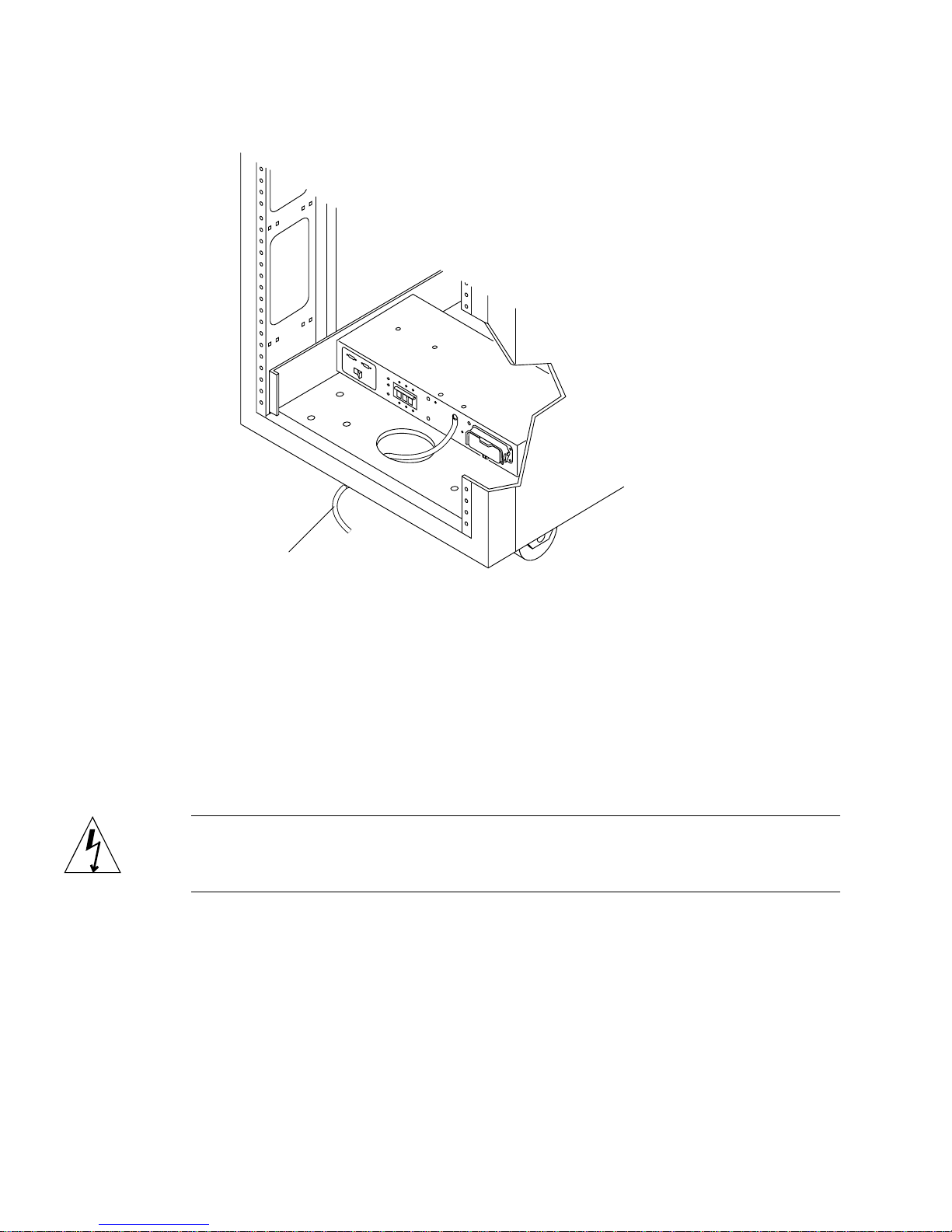
Grounding cable
FIGURE 2-12 Attaching the Grounding Cable to the Front Power Sequencer
6. Attach the other end of the grounding cable to either an external
grounding post or something attached to a grounding post.
You are now ready to connect the power cables, as described in the next section.
Connecting the Power Cables
Caution – T he system is designe d to work with single-pha se power systems tha t
have a grounded neutral conductor. To reduce the risk of electric shock, do not
connect the syste m to any other type of powe r system.
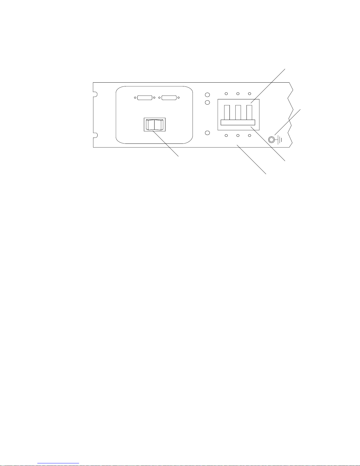
1. Verify that each AC power sequencer circuit breaker is in the Off position
(
FIGURE 2-13).
2. Verify that the Local/Off/Remote switch is in the Remote position on each power
sequencer (
FIGURE 2-13).
24 Sun StorEdge 6920 System Getting Started Guide • May 2004
Page 43
Power off
Grounding
screw
Power on
J15
OUT
LOCAL
SWITCHED OUTLET CONTROL
OFF
IN
J14
REMOTE
POWER AVAILABLE SWITCHED OUTLETS
Local/Off/Remote switch
I
P
A
M
E
N
R
O
W
AC power sequencer
circuit breaker
FIGURE 2-13 Rear Power Sequencer Control Panel
3. Check the electrical ratings label on the seria l number labe l attached to the power
sequencer. Verify that the stated rating of each p ower sequencer matches the AC
input voltage to the system (see “Power Sequencer Electrical Specifications” on
page 103).
4. Connect each power cable to the front and rear power sequencers (
FIGURE 2-14):
a. Flip open the latch covers of each cable to access the connectors.
b. Connect the female end of one power cable to the rear power sequencer
connector.
c. Connect the female end of the other power cable to the front power sequencer
connector.
d. Pull t he latch covers over the power cables to secure them to the power socke ts.
e. Route each power cabl e directly through t he opening in th e base of the cabinet .
Chapter 2 Installing the System 25
Page 44
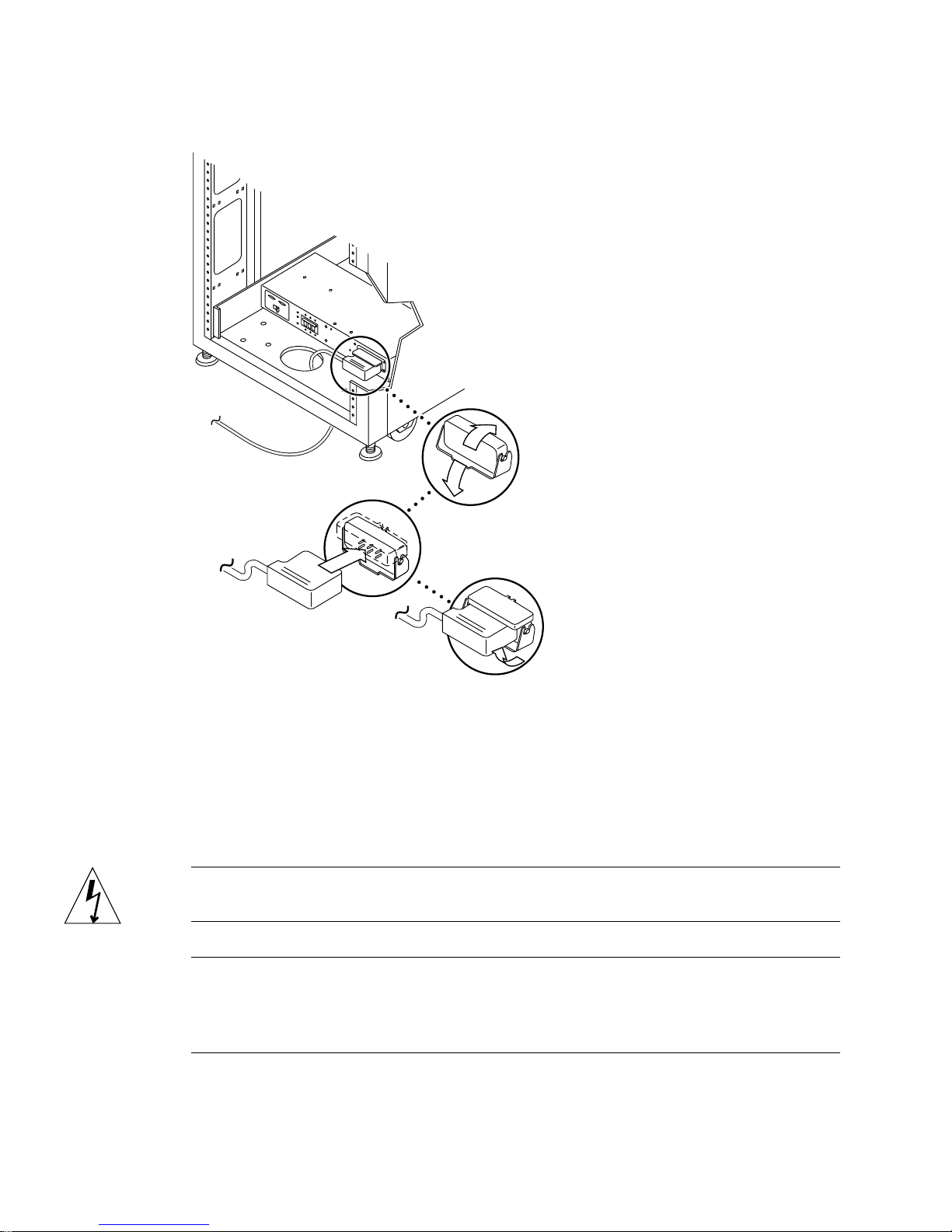
FIGURE 2-14 Connecting the Power Cables
5. Connect the other end of each power cable to a grounded outlet.
The following connector types are provided on the power cable:
■ NEMA L6-30P for 200V to 240V North Amer ican operation
■ 32A, single-phase, I EC 309 connector for 220V to 240V int ernational operation
Caution – To reduce the ri sk of electric shock, str ictly observe all Caution and Note
statements in the following procedure.
Note – If the appropriate mating receptacle is unavailable, the connector can be
removed from the cable, and the cable can then be permanently connected to a
dedicated branch circuit by a qualified electrician. Check local electrical codes for
proper installation requirements.
26 Sun StorEdge 6920 System Getting Started Guide • May 2004
Page 45
After you have connected the power cables, you are ready to power on the system,
as described in the next section.
Powering On the System
Caution – To avoid d amage to internal circuits, do not connect or disconnect any
cable while the FRU associated with the cable is powered on.
1. Verify that the AC power cable of the system is connected to the correct AC outlet.
Caution – Do not disconnect the AC power cable from the outlet when working on
or in the system. This connection provides a grounding path that prevents damage
from electrostatic discharge.
2. At the bottom front and bottom back of the base cabinet, set the AC power
sequencer circuit breakers to the “On” position (
As soon as you connect AC power to t he system, the Storage Se rvice Processor
powers up.
FIGURE 2-13).
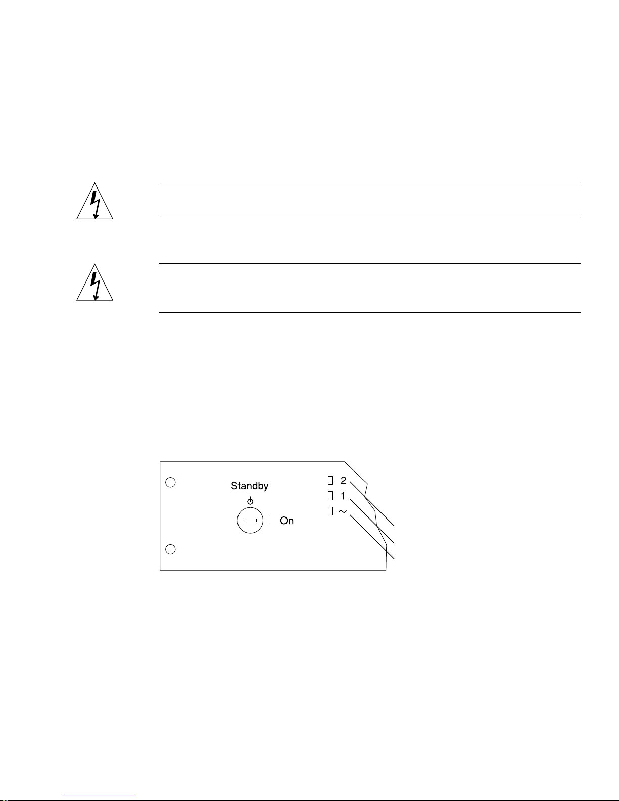
The three power indicators on the front sequencer panel show the status of the front
power sequencer (
FIGURE 2-15). The main AC power light emitting diode (LED)
illuminates when power is applied to the system. The LED for sequencer stage 1
illuminates next, followed immediately by the LED for sequencer stage 2.
Sequencer stage 2
Sequencer stage 1
Main AC power
FIGURE 2-15 Front Sequencer Status Lights
a. Verify that the three front sequencer status lights are illuminated (FIGURE 2-15),
indicating that power is applied to the Stor age Service Proce ssor, Ethernet hub,
and Storage Service Process or accessory tray.
Chapter 2 Installing the System 27
Page 46

Note – The Storage Service Processor and Storage Service Processor accessory tray
are already pow ered on beca use t hey are conn ec ted to t he u nsw itch ed p ower outl ets .
b. Verify that there are three gr een LEDs illumin ated on the r ear power seque ncer
panel.
3. At the bottom front and bottom back of the system, set the Local/Off/Remote
switch to the “Local” position.
The system is now powered on.
4. Replace the front trim panel to its original location at the bottom front of the
cabinet.
5. Turn the key switch, located at the bottom of the front panel, to the On position
(
FIGURE 2-11).
Installing the USB Flash Disk
The Sun StorEdge 6920 syst em ships with a universa l serial bus (USB) flash disk to
back up the Storage Service Processor configuration files. In the event of a Storage
Service Processor failure, Field Service personnel can use the flash disk to restore the
original configuration t o a replacement Storage Service Processor.
Note – Do not connect a USB flash disk with an image that you want to restore to a
working Storage Service Processor or any other USB port, since the image on the
flash disk could be overwritten.
Note – The flash disk is formatted for the Solaris Operating System. Do not connect
it to a PC, since the Microsoft Windows operating system will not recognize it and
will ask if you want to format the disk.
28 Sun StorEdge 6920 System Getting Started Guide • May 2004
Page 47
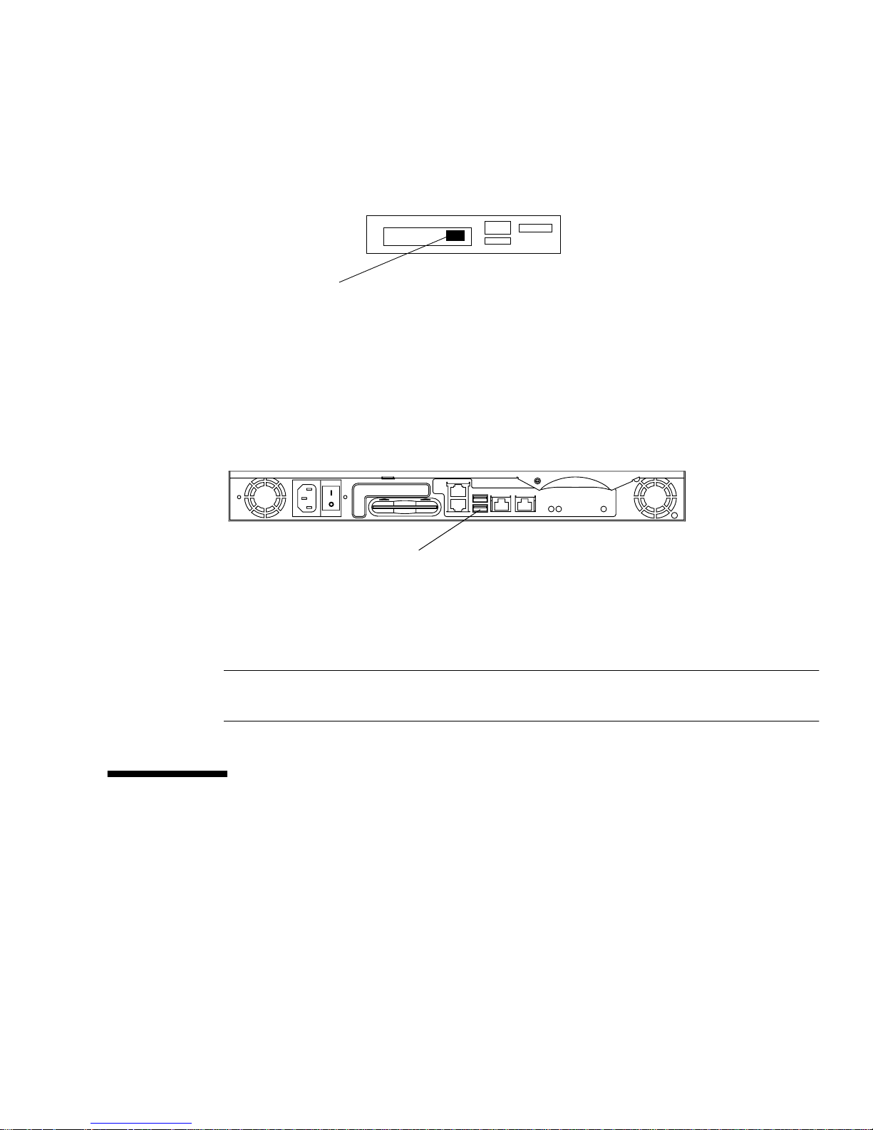
1. If the USB flash di sk has a write protection sw itch, verify that it is set to the
unlock (write enabled) symbol.
The flash disk is write enabled when the write protection switch is set to the right, as
shown below:
Switch in writeenabled positio n
FIGURE 2-16 USB Flash Disk Write Protection Switch
2. At the right side of the service panel, loosen the four screws and swing the panel
open to gain access to the back of the Storage S ervice Processor.
3. Insert the USB flash disk into USB Port 1 on the back panel of the Storage Service
Processor.
USB Port 1
FIGURE 2-17 Storage Service Processor: USB Port 1
4. To verify that the flash disk is installed corr ectly, look for a steady green LED
light located at the top of the disk.
Note – The LED is located on the top of the flash disk and may be difficult to see
when it is installed.
Setting Up the Remote Response Service
The Sun StorEdge Remote Respon se servic e sends ale rts from the Sun StorE dge 6920
system to the Sun Service Center. When you activate this service, the Storage Service
Processor continually moni tors the messages sen t to the system log by the soft ware
and firmware in the system subsystems. If a messag e contains an alert, t he system
contacts the Sun Service Center.
Chapter 2 Installing the System 29
Page 48

Note – If remote monitoring via the Sun StorEdge Remote Response service is not
possible, configure RAS Telemetry for this system. The type of telemetry sent
includes information such as firmware levels, WWNs, serial numbers, event logs,
and system uptime. Customer data is not sent. The telemetry gathered will allow
Sun to know if your system requires implementation of a field information notice
(FIN), field change order (FCO), or firmware upgrade. To se t up encrypted email for
RAS Telemetry, refer to the instructions in “Setting Site Information for Diagnostics
and Monitoring” on page 54 to configu re the NSCC Remote Provider Service.
All of th e hardware an d softw are required to use the rem ote respo nse serv ice is
included wi th the system. To set up the servic e at your site, y ou must:
■ Connect a dedicated analog telephone line with dial-out and dial-in capability.
Plug the dedicated telephone line into the PHONE jack on the service panel of the
system cabine t.
■ Set up an SSRR notification provider as described in “Setting Site Information for
Diagnostics and Monitoring” on page 54.
■ Gather the information you need to activate the service using the worksheet in
Appendix A as a guide.
■ Contact your local Sun Service Center and ask for Sun StorEdge Remote Response
installation activation.
The modem installed in the system cabinet is qualified for use in most countries (see
Appendix A for a list of countries) with no modification required.
If you want to connect multiple Sun StorEdge 69 20 systems to share a sing le
telephone line, you must complete the installation and initial configuration of the
first system. You can then connect additional Sun StorEdge 6920 sy stems, as
described in “Connecting Multiple Systems” on page 77. If you want to connect the
Sun StorEdge 6920 system to a Sun StorEdge 6320 system, contact the Sun Service
Center.
Connecting Data Hosts
The method you use to connect data hosts depe nds on how you pl an to use the
system. The Sun StorEdge 6920 system supports both storage area network (SAN)
and direct attached storage (DAS) configurations for host-side server connections.
30 Sun StorEdge 6920 System Getting Started Guide • May 2004
Page 49

Redundant Fibre Channel (FC) ports located on the two I/O panels of the service
panel are reserved for data host connections. A system can be configured for 16 FC
or 32 FC ports. A 16-FC port configuration includes two storage resource card (SRC)
sets, each consisting of two SRC processor cards and two storage I/O (SIO) cards.
You can add more FC ports to the system by inst alling additional SRC sets.
With a 16-FC port configuration, use the four leftmost ports (ports 1 through 4) of
the lower I/O panel to connect data hosts. The four rightmost ports (ports 5 through
8) are connected to arrays in the system.
Port connections are typically evenly allocated between data hosts and arrays.
However, you can allocate additional ports for either host or array connections,
depending on the needs at your site. If you need additional ports for host
connections, refer to “Selecting Ports for Additional Host Connections” on page 33
for guidelines. If you need additional ports for array connections, refer to “Selecting
Ports for Additional Storage Connections” on page 34 for guidelines.
Note – If you allocate more than half of the available ports for SAN or DAS hosts,
you will need an additional 1-meter LC-to-SC cable for each HBA port to physically
connect the DSP to the service panel.
Chapter 2 Installing the System 31
Page 50
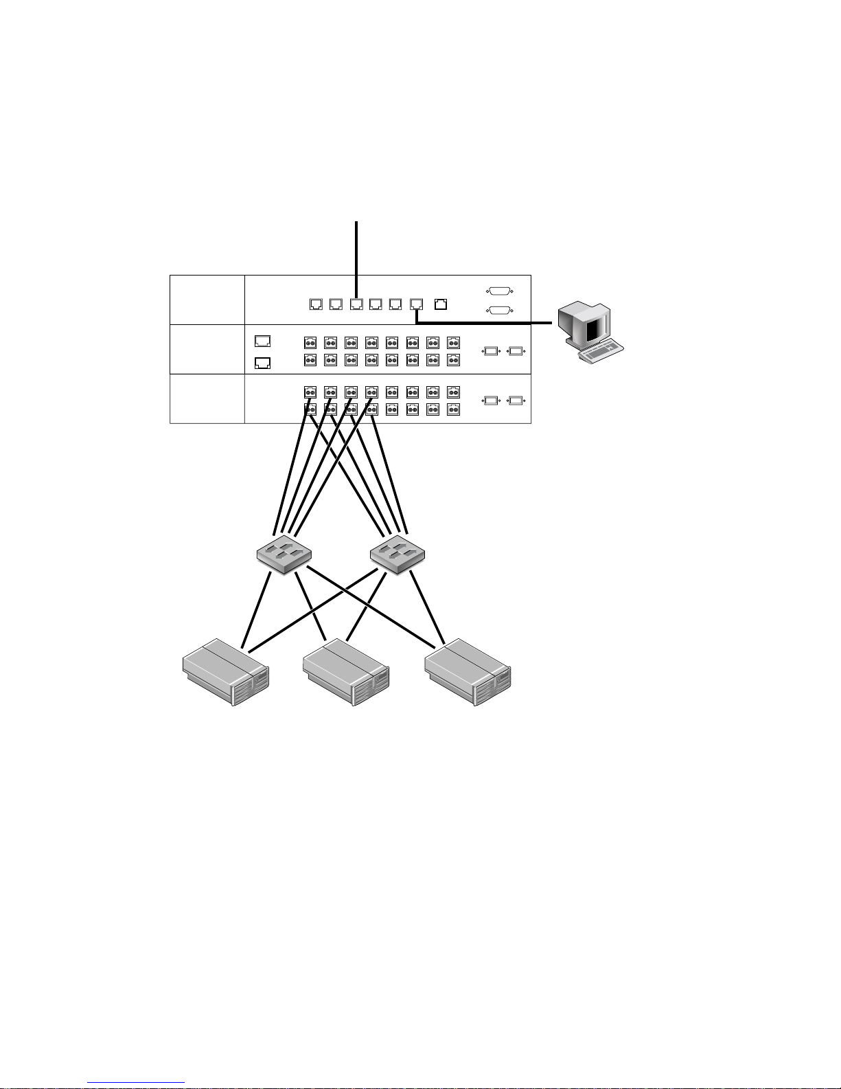
Connecting Hosts to a SAN
FIGURE 2-18 shows a sample configuration of data hosts connected to external SAN
FC switches from redundant ports 1 through 4 of the lower I/O panel.
LAN
SERVICE
PROCESSOR
PANEL
I/O
I/O
EXP ENET 1
EXP ENET 2
NPORT
A
B
NPORT
C
D
SP LAN
SP LANINUSER
OUT
1
2345678
1
2345678
SERVICE
SERVICE
AUX
LAN
SERIAL
CONSOLE
PHONE
PWR SEQUENCER
OUT FRONT
OUT REAR
EXP 1
FC1
A
EXP 2
FC1
B
Fibre Channel
Switches
FC2
FC2
Data Host
Servers
Management
Console
FIGURE 2-18 Connecting Hosts to a SAN
For more information about the allocation of I/O ports for SAN and DAS hosts, go
to the online help. Click the Search tab and type FC ports.
32 Sun StorEdge 6920 System Getting Started Guide • May 2004
Page 51
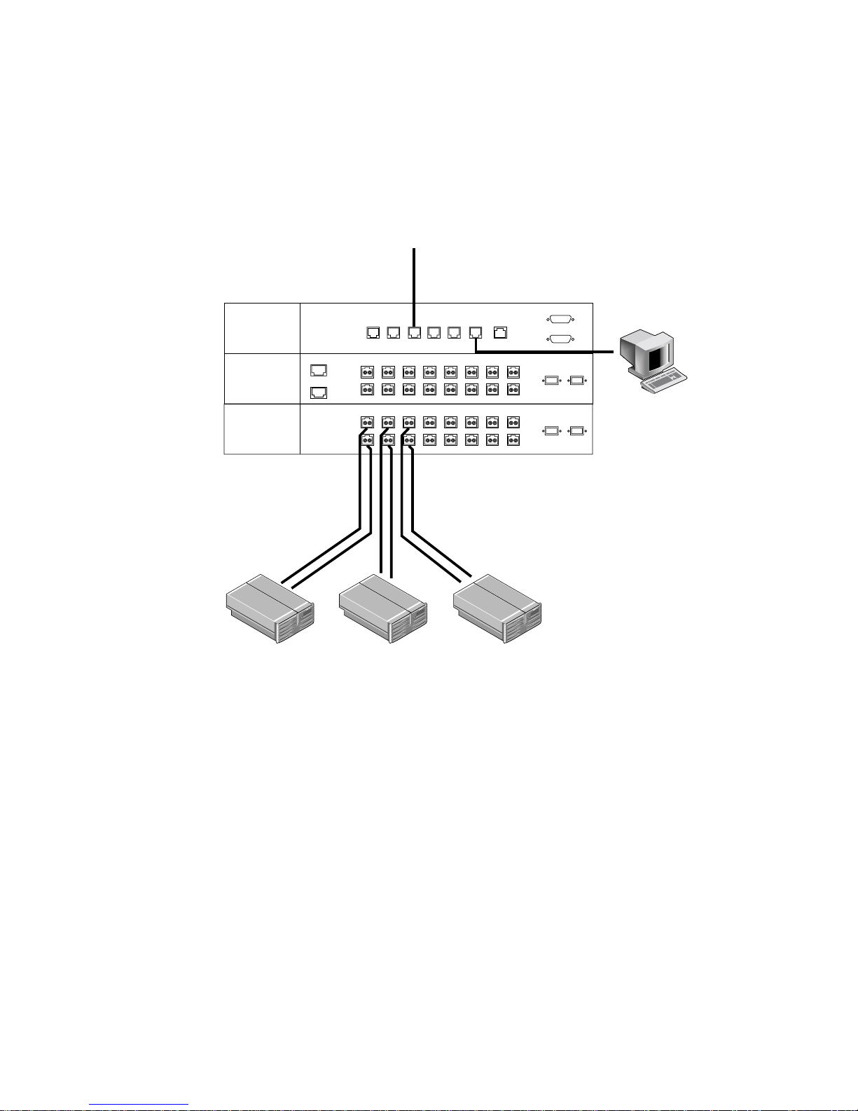
Connecting Hosts Directly
The Sun StorEdge 6920 system supports direct attached storage (DAS), allowing data
hosts to connect directly to storage .
connected directly to the Sun StorEdge 6920 system.
LAN
FIGURE 2-19 shows an example of data hosts
SERVICE
PROCESSOR
PANEL
I/O
I/O
EXP ENET 1
EXP ENET 2
NPORT
A
B
NPORT
C
D
SP LAN
SP LANINUSER
OUT
1
2345678
2345678
1
SERVICE
SERVICE
AUX
LAN
SERIAL
CONSOLE
PHONE
PWR SEQUENCER
OUT FRONT
OUT REAR
EXP 1
FC1
A
EXP 2
FC1
B
Management
FC2
FC2
Console
Data Host
Servers
FIGURE 2-19 Connecting Hosts Directly
After you finish connecti ng data hosts, you are ready to run the initia l setup script.
Go to “Running the Initial Configuration Script” on page 38.
Selecting Ports for Additional Host Connections
Ports in the columns marked 1, 2, 3, and 4 are specifically for host connections. If
you need to allocate more ports for host attachment, take additional ports from right
to left and top to bottom.
That is, once yo u have used all por ts in columns 1 th rough 4, use the top most
available port in column 5 and work your way down that column. If necessary, go to
column 6 and use ports from top to bottom, and so on.
Chapter 2 Installing the System 33
Page 52

Note – You cannot use ports in column 8 for host connections.
Selecting Ports for Additional Storage
Connections
Ports in the columns marked 8, 7, 6, and 5 are specifically for storage connections. If
you need to allocate more ports for storage attachment, you need to connect ports,
take additional ports from left to right and top to bottom.
That is, once yo u have used all por ts in columns 8 th rough 5, use the top most
available port in column 4 and work your way down that column. If necessary, go to
column 3 and use ports from top to bottom, and so on.
Note – You cannot use ports in column 8 for storage connections.
Troubleshooting Tips
Use this list as a guide for isolating common installation problems:
■ Verify that all power and data cables are properly installed and in the right
locations.
■ Verify that all FC connections, cable adapters, and Gigabit Interface Converters
(GBICs) are installed and secure.
■ Verify that the power to the system is turned on.
■ Check the AC power sequencer control panel:
■ If the switched outlet LEDs are not illu minated, ch eck the posi tion of the k ey
switch.
■ If one switched outlet LED is illuminated but the other is not, check the status
of the power sequencer for the unlit LED.
■ If any FRU has an amber LED, a service action is required. Go to the Storage
Automated Diagnostic Environment Event Advisor for information.
■ If some FRUs have power and others do not, check the power-on switch on the
FRUs that do not have power.
For more information about FRU fault detection and isolation, go to Service > Event
Advisor in the Storage Autom ated Diagnostic Environment .
34 Sun StorEdge 6920 System Getting Started Guide • May 2004
Page 53

At a Glance:
What Are the Key Benefits?
Installing the
System
This chapter provides step-by-step instructions for phys ically setting
up and installing a Sun StorEdge 692 0 s ystem.
The system is preconfigured at the factory, so there are only a minimum
number of steps to perform. The service panel makes cabling the
system quick and easy. You do not need to worry about how to
configure internal IP addressing or internal firewall support.
What Are the Steps?
The basic hardware installation steps are:
1. Move, position, secure, and stabilize the base cabinet.
2. Connect an optional exp a ns ion cabinet.
3. Power on the system.
4. Install the USB flash disk.
5. Connect a telephone li ne for Sun StorEdge Remote Respons e
service.
6. Connect hosts to th e sy stem.
For More Information
If you encounter problems during the installation procedure, refer to
the “Troubleshooting Tips” on page 34.
For additional information about the hardware and software described
in this chapter, see the online help.
Chapter 2 Installing the System 35
Page 54

36 Sun StorEdge 6920 System Getting Started Guide • May 2004
Page 55

CHAPTER
3
Configuring the System
This chapter provides procedures for initial configuration of the system. It includes
the follo wing sec tions:
■ “Before You Begin” on page 38
■ “Running the Initial Configuration Script” on page 38
■ “Logging In and Navigating the System Using the GUI” on page 45
■ “Completing the Initial Configuration” on page 53
■ “Setting the Expansion Cabinet Array Addresses” on page 56
■ “Provisioning Storage” on page 57
■ “Viewing the Default Configuration Settings” on page 66
■ “Creating Volumes” on page 67
■ “Common Storage Configur ation Tasks” on page 69
You can also refer to “At a Glance: Configu ring the System” on page 73 for a highlevel overview of the procedures described in this chapter.
37
Page 56

Before You Begin
Before you can begin to perform the system configuration procedures in this chapter,
you must compl ete the follo wing steps:
1. Complete the physical installation procedures in “Installing the System” on
page 11 in Chapter 2.
2. Use the Information Collection Worksheet (Appendix E) to gather the information
you will need to complete the initial configuration. The system will prompt you
for this information during the setup script.
Running the Initial Configuration Script
You establish the initial configuration of the Sun StorEdge 6920 system by logging in
to the system through the serial connection from a Sun workstation, a PC, or another
terminal type .
This procedure describes how to establish the serial connection, log in through the
service console, and run the initial configuration script. This script guides you
through the configuration steps for a new system.
Establishing the Serial Connection
1. Locate the serial connection field-re placeable units (FRUs) (TABLE D-2) that came
with the system.
2. Assemble the RJ45 cable with the adapter that fits either the DB9 or the DB25
serial port of a laptop, terminal, or Solaris workstation.
3. Connect the serial cable from the Service Console port on the service panel to the
workstation.
4. Configure the console settings:
■
If you are using a Sun workstation, connect through the serial ports using the tip
command for the appropriate port, as shown in the following example:
[3]user1: tip - 9600/dev/ttya
connected
38 Sun StorEdge 6920 System Getting Started Guide • May 2004
Page 57

Serial port 1 corresponds to /dev/ttya and serial port 2 c orresponds to
/dev/ttyb.
■ If you are using a terminal or a terminal emulation program, open a term inal
window and configure the console settings as follows:
Bits per Second: 9600
Data Bits: 8
Parity: None
Stop Bits: 1
Flow Control: None
Running the Initial Configuration Script
1. Log in to the network terminal concentrator (NTC) using the following login
name and password:
login: rss
password: sun1rss
2. Switch to the system’s Storage Service Processor.
ntc0: connect local port_2
3. Press Return several times until the login prompt is displayed.
new_sp console login:
4. Log in to the console using the following login name and password:
new_sp console login: setup
Password: !setup
When you log in as setup, the initial configuration utility script automatically runs.
Chapter 3 Configuring the System 39
Page 58

5. Select Initial con figuration from the list of options by typing 1.
***********************************************
* StorEdge 6920 Initial Configuration Utility *
***********************************************
Select the operation you wish to perform:
1. Initial configuration
2. Restore previously defined configuration
3. Unconfigure
4. Enable SW support for Lights Out Operation
Your Choice: 1
The script searches for oth er attached Sun StorEdge 6 920 systems and displays a list
of any that are found with thei r system numbers, suc h as sp0 or sp1.
Initial configuration is setting up the id
and network parameters for your StorEdge 6920.
The current hostname for this StorEdge 6920 system is new_sp.
Searching for other existing StorEdge 6920 systems on your
network...
Searching for a StorEdge 6920 with hostname sp0 ...
Searching for a StorEdge 6920 with hostname sp1 ...
Searching for a StorEdge 6920 with hostname sp2 ...
Searching for a StorEdge 6920 with hostname sp3 ...
Searching for a StorEdge 6920 with hostname sp4 ...
Searching for a StorEdge 6920 with hostname sp5 ...
Searching for a StorEdge 6920 with hostname sp6 ...
Searching for a StorEdge 6920 with hostname sp7 ...
No other StorEdge 6920 systems are currently configured on your
network.
Note – If you have multiple Sun StorEdge 6920 systems and want the Sun StorEdge
Remote Res ponse serv ice to mo nitor th e systems through a com mon tel ephone li ne,
you must assign each Storage Service Processor a unique ID. The system containing
the modem w ith the tel eph o ne lin e c onn ec tio n mu st b e a ssi g ned a s ys te m I D of sp0.
For more information about connecting multiple systems, see “Connecting Multiple
Systems” on pa ge 77.
40 Sun StorEdge 6920 System Getting Started Guide • May 2004
Page 59

6. Specify a unique host name for the new system by typing a number from 0
through 7.
If this is the first system at the site, type 0. There can be a maximu m of e i gh t sy s tems
in one c onfigurat io n ( sp0 through sp7). If more than one Su n StorEd ge 69 20 sy stem
is installed at your site, use the next highest number in sequence for each installed
system.
Please enter the StorEdge 6920 Id.
A valid value is a digit between 0 and 7.
Your Choice: 0
7. At the prompts, provide information about your network configuration.
Type 1 to configure dynamic host control protocol (DHCP) IP addressing, or 2 to
configure a fixed or stati c IP address for the system. Sun recomm ends us ing fixe d IP
addressing. If you choose DHCP, binding must be persistent and not dynamic.
8. Specify the remaining network configuration information at each prompt.
Network Settings:
-------------------Do you wish to use DHCP or Fixed Network Addresses?
1. DHCP
2. Fixed
Your Choice: 2
Please enter the IP Address for the StorEdge 6920: XX.X.XX.X
Please enter the Gateway Address for the StorEdge 6920: XX.X.XX.X
Please enter the Network Mask for the StorEdge 6920: XXX.XXX.XXX.X
Please enter the Nameserver IP Address for the StorEdge 6920:
XX.X.X.X
Please enter the Nameserver Domain for the StorEdge 6920:
yourserver.com
Chapter 3 Configuring the System 41
Page 60

9. If necessary, modify the time zone.
Type 1 to select your time zone from a list. Or type 2 and enter the time zone as
shown in the following example:
Current TZ = GMT
Modify TZ?
------------
1. Select Timezone from list
2. Enter Timezone (if known)
3. No Change.
Your Choice: 2
Enter Timezone (Example: US/Mountain): US/Eastern
Current date and time = Thu Jan 6 06:10:02 GMT 2000
10. If necessary, modify the current date and time.
Type 1 to change the date and ti me. Enter th e date in mm/d d/yyyy form at and
enter the time in one of the formats shown in the following example:
Modify Date and Time?
-----------------------
1. Change Date and Time
2. No Change.
Your Choice: 1
Please enter the date for the StorEdge 6x20 (mm/dd/yyyy):
04/08/2004
Please enter the time for the StorEdge 6x20 (hh:mm; hh 00-23, mm
00-59): 13:42
11. When prompted, verify the accuracy of your responses by typing y.
Typing n results in the network configuration questions being asked again. If you
press Return at each question, your original answer is retained.
Typing y or pressing the Return key starts the automatic configuration running.
After the configuration completes, the NTC reboots, and the following message is
displayed.
42 Sun StorEdge 6920 System Getting Started Guide • May 2004
Page 61

Note – The NTC takes ap proximately two minutes to reboot.
Are all of the above settings correct? (Y/N) y
******************************************
* Performing StorEdge 6920 Configuration *
******************************************
..........
..........
..........
Return Code (0) : Successful completion
NOTE: The NTC Configuration was successful. The NTC will be
reinitialized in less than two minutes. Please press "Enter"
when prompted in order to proceed with configuration, then log off.
Disconnect from the NTC, and wait ap proximately two minutes before
reconnecting. If the following network verification is
successful, you may begin other configuration tasks.
Successfully completed.
12. Log back in to the system from the terminal window, using the same login and
password.
login: rss
Password: sun1rss
Lantronix SCS400 Version B2.0/202(021016)
Type HELP at the ’ntc0: ’ prompt for assistance.
13. Specify the local port to which you want to connect, as shown in the following
example:
ntc0: connect local port_2
Local protocol emulation 1.0 - Local Switch: <^[>.
Chapter 3 Configuring the System 43
Page 62

14. Press Return to continue with the initial configuration.
Press enter to continue....
******************************************
* Testing StorEdge 6x20 Network Settings *
******************************************
Please enter an IP Address for another host on your network
to enable validation of your network settings:
The system prompts you for the IP address of a nother atta ched host on t he Ethernet
LAN.
15. Typ e the IP address of an available host on the si te LAN and press Return.
The system pings the other host and reports success, if the network configuration
steps were succ essful. The co nsole prompt is t hen displa yed.
Please enter an IP Address for another host on your network
to enable validation of your network settings: 123.45.x.yy
Please wait...
Ping successful, your firewall is configured.
se6000configure Successfully Completed.
Sun StorEdge 6920 Service Processor
|--------------------------------------------------------------|
| This system is for the use of authorized users only. |
| Individuals using this computer system without authority, or in |
| excess of their authority, are subject to having all of their |
| activities on this system monitored an d recorded by system |
| personnel. |
| |
| In the course of monitoring individuals improperly using this |
| system, or in the course of system maintenance, the activities |
| of authorized users may also be monito red. |
| |
| Anyone using this system expressly consents to such monitoring |
| and is advised that if such monitoring reveals possible |
| evidence of criminal activity, system personnel may provide the |
| evidence of such monitoring to law enforcement officials. |
|--------------------------------------------------------------|
sp0 console login:
44 Sun StorEdge 6920 System Getting Started Guide • May 2004
Page 63

16. Clear alerts.
You can clear alerts later by logging in to the system as described in “Logging In to
the System” on page 46 and selecting Storage Automated Diagnostic Environment.
17. To disconnect from the serial connection, type the following command:
a ~.
The terminal session returns to t he shell.
This completes the initial configuration of the system. You are now ready to log into
the system.
Logging In and Navigating the System
Using the GUI
The Sun StorEdge 6920 syst em is controlled through eith er a web browser graphical
user interface (GUI) or a command-line interfac e (CLI). You can access the GUI from
a web browser on any management host that is connected to the site LAN. You can
access the CLI through a thin-scripting client from any management host connected
to the site LAN. The thin-scripting client for the Solaris Operating System is
provided on the Host Installation CD that is delivered with the system.
Note – For information about logging in to and navigating the system using the
CLI, see the Sun StorEdge 69 20 System Ho st Installa tion Softw are Guide, availa ble on
the Host Installat ion CD that ships with the system.
This section includes the following topics:
■ “About User Accoun ts” on page 46
■ “Logging In to the System” on page 46
■ “Navigating the Syst em” on page 49
Chapter 3 Configuring the System 45
Page 64

About User Accounts
Before you log in to the system, you should understand the types of user accounts
that are availa ble. The typ e of account you log in to de termines t he level of sy stem
access. There are three types of user accounts (
TABLE 3-1 User Accounts
Default
Account Type User Name
Password Description
TABLE 3-1).
Administrator
User
Storage User storage !storage Log i n as a storage administrator to configure
Guest User guest !guest Instruct users to log in as guest users if you do
admin !admin Log in as a system administrator to configure
system-wide settings.
A system administrator has all administration
privileges. This user can mo dify users an d
system attributes on the Administration page.
and manage storage on the system.
A storage administrator can use the features
related to storage con figuration, in cluding
array management and managing storage
domains, storage pools, and volumes.
This user can access the Administration page,
but cannot modify the settings.
not want to give them read/write permissions
on the sy stem.
A guest has rea d-only privileg es and can only
view the info rmation. This user cannot modify
any settings or features.
The admin and storage user accounts are exclusive. If a second user logs on to an
account already i n use, t he se ssion of the first user w ill te rminate . You can use more
than one guest accou nt at a t ime. You cannot creat e new a ccount types.
For information on how to change the default password for an account, see
“Changing Passwords” in the online help.
Logging In to the System
To log in to the system, you open a web browser and enter your user name and
password at the main Sun Web Console login page. You can run a browser on any
system that is connected to the user LAN port.
46 Sun StorEdge 6920 System Getting Started Guide • May 2004
Page 65
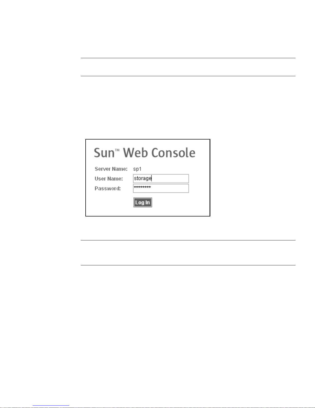
1. Open a supported browser.
Tip – For information about supported web browsers, see the Sun StorEdge 6920
System Relea se Notes.
2. Enter the IP address of th e system in this forma t: https://IPaddress:6789
This IPaddress is the IP address of the site LAN interface. You assigned the IP address
while running the installation script. (See “Establishing the Serial Connection” on
page 38.)
The system displays the Sun Web Console login page (
FIGURE 3-1 Sun Web Console Log in Page
FIGURE 3-1).
Note – “Server Nam e” is the nam e of the Stora ge Service Pro cessor in the Sun
StorEdge 6920 system and is in t he form spn, where n i s the number entered in
Step 6 of “Running the Initial Configuration Script” on page 39; for example, sp1.
3. Enter the user name and password.
For information about user accounts and passwords, see “About User Accounts” on
page 46.
Chapter 3 Configuring the System 47
Page 66
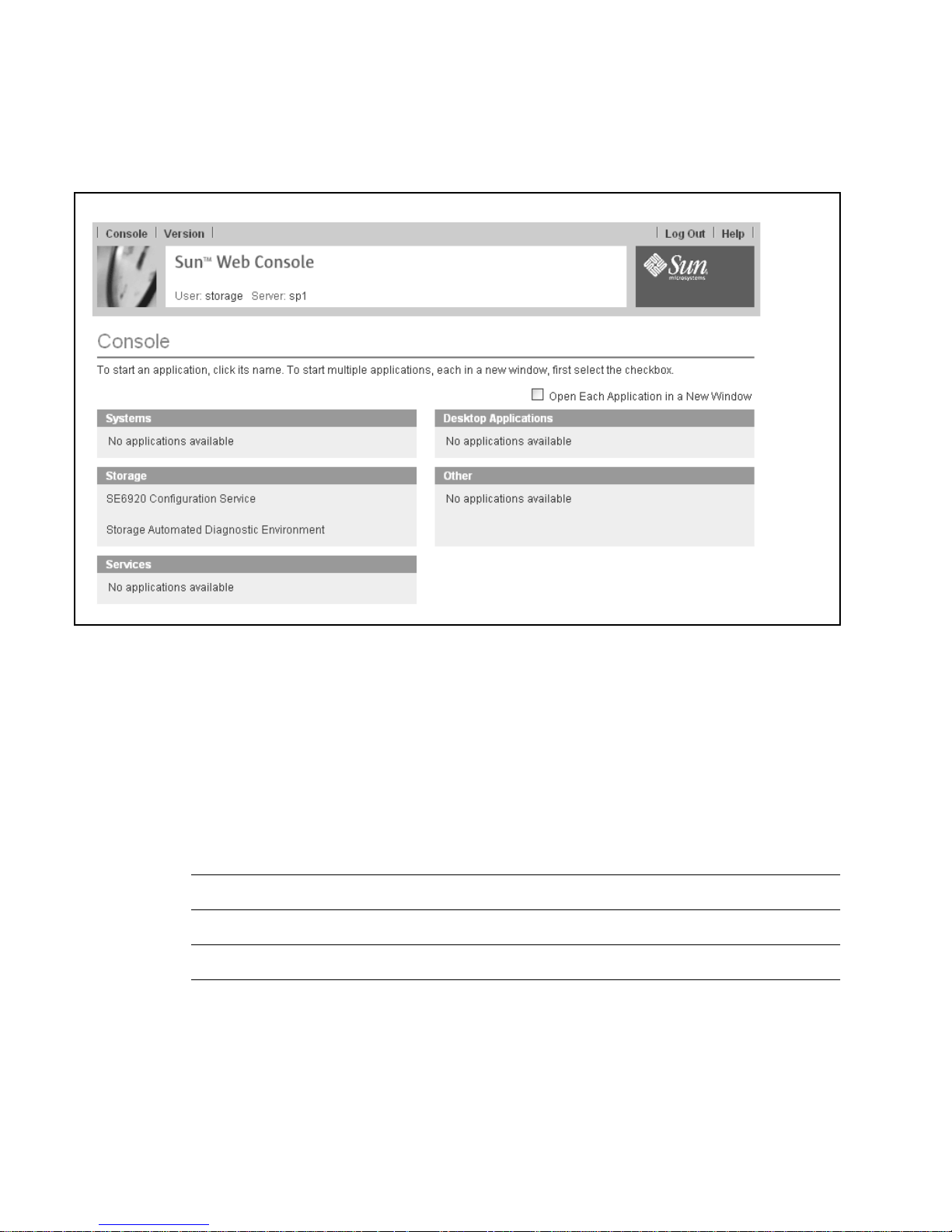
4. Click the Log In button.
The system displays the Sun Web Console page (
FIGURE 3-2).
FIGURE 3-2 Sun Web Console Page
5. Select one of the entry points into the system:
■ SE6920 Configuration Service
■ Storage Automated Diagnostic Environment
The system displays the appropriate web page, based on your selection.
At this point, you are logged in to the system. Before you begin configuring the
system, you should become familiar with the GUI. Go to “Navigating the System”
on page 49.
Tip – To log out of the GUI, click Log Out in the upper right corner of any page.
Note – The connection closes automatically if there is no activity for 30 minutes.
48 Sun StorEdge 6920 System Getting Started Guide • May 2004
Page 67
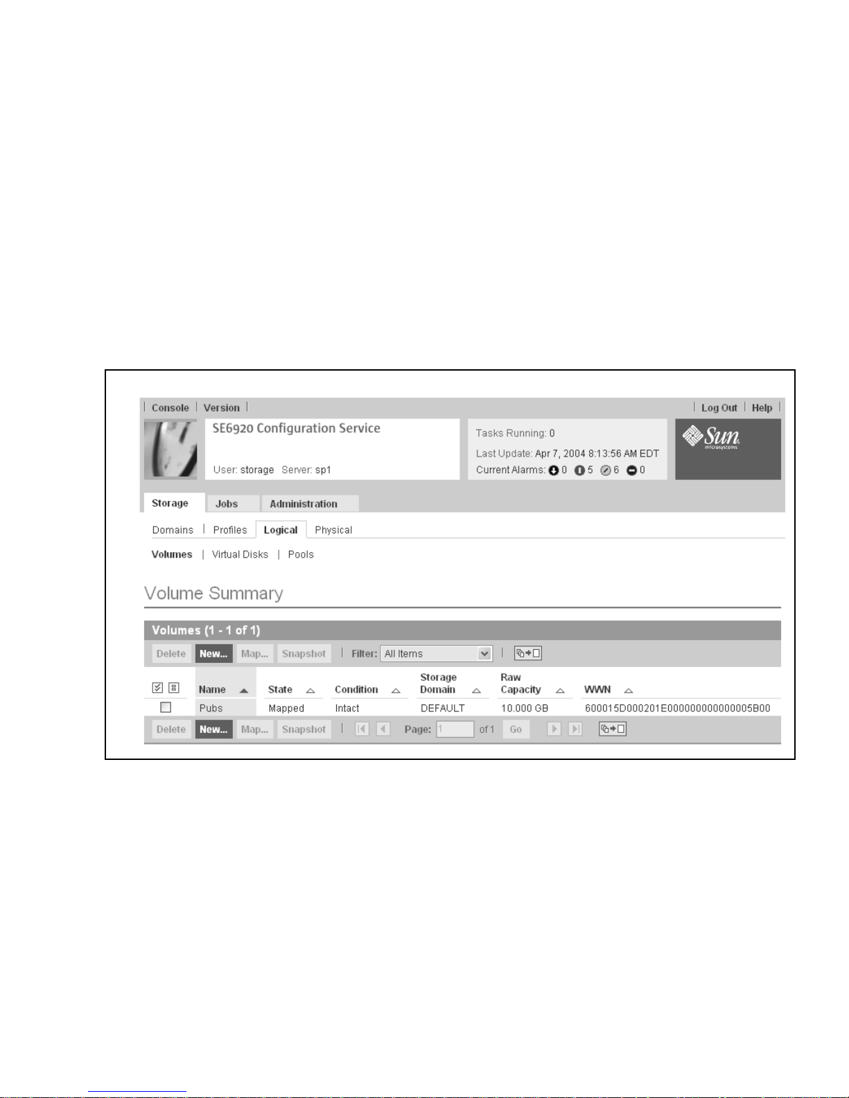
Navigating the System
This section describes the GUI elements and navigation methods. It includes the
following topics:
■ “About the GUI Layout” on page 49
■ “Getting Help” on page 52
About the GUI Layout
The Sun StorEdge 6920 system GUI is the main interface for the system (FIGURE 3-3).
FIGURE 3-3 Sun StorEdge 6920 Syste m Graphical Use r Interface (GUI)
This section describes the main elements of the GUI:
■ Access buttons
■ Quick status displays
■ Navigational tabs
■ Page content and act ions
Chapter 3 Configuring the System 49
Page 68
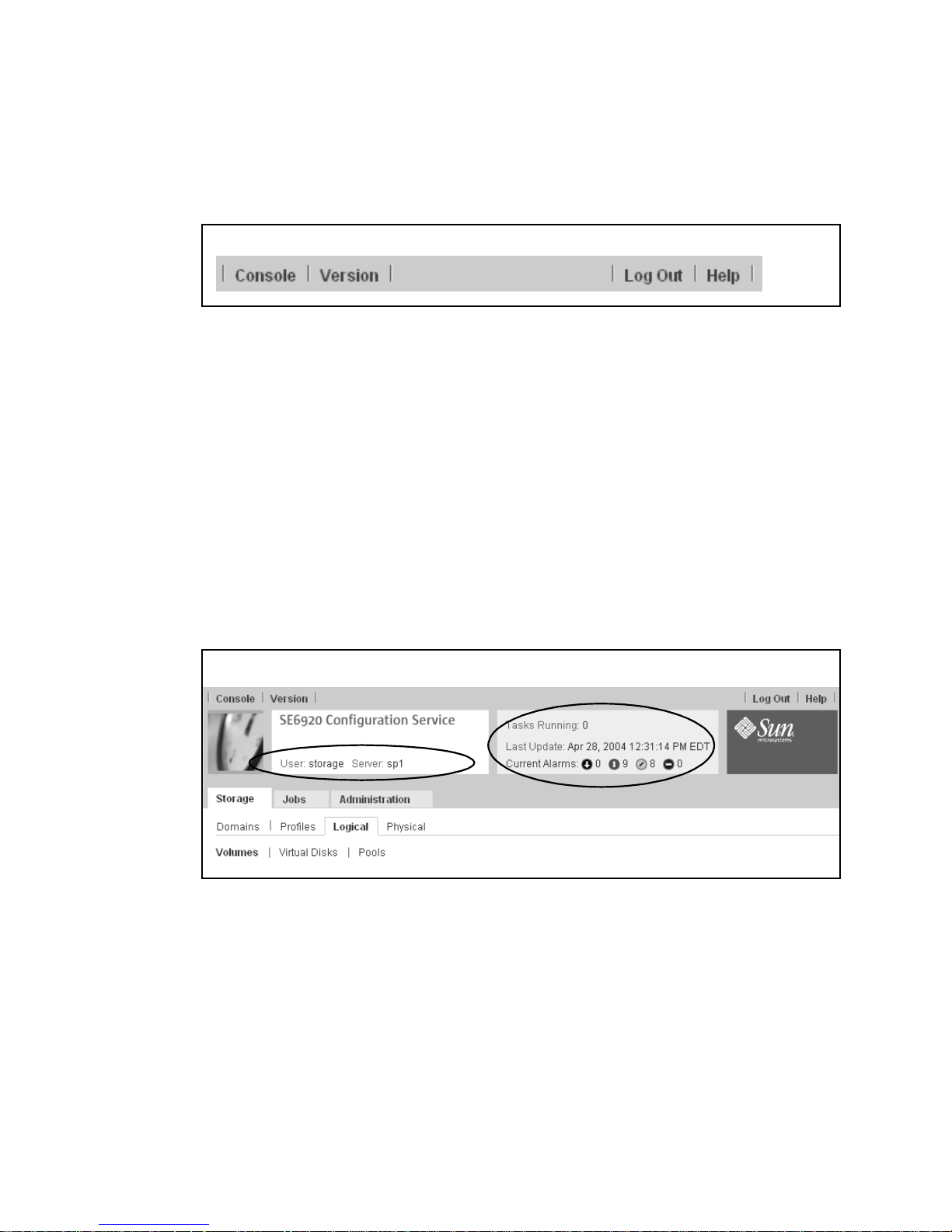
Access Buttons
The access buttons are located across the top of the web page and enable you to
access some of the most common funct ions and displays.
FIGURE 3-4 Navigating the GUI: Access Buttons
The access buttons have the following functions:
■ Console returns you to the Sun We b Console p age.
■ Version displays version information.
■ Log Out logs you out of the system and returns you to the Sun Web Console login
page.
■ Help opens the online help system.
Quick Status Displays
The quick status displays provide user role and server name information, as well as
the status of current alarm.
(2)
(1)
FIGURE 3-5 Navigating the GUI: Quick Status Display
The displays provide the following information:
■ The display on the left (1) shows the current user role and server name.
■ The display on the right (2) shows the current status of the system, including the
number of current jobs, date and time of the last system update, and current
alarms.
50 Sun StorEdge 6920 System Getting Started Guide • May 2004
Page 69
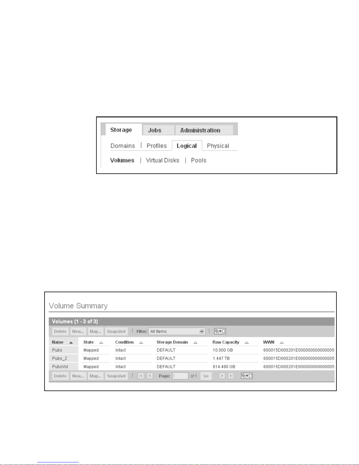
For a descr iption o f the alarm s ymbols , see th e onl ine hel p. Click the Search ta b and
type viewing al arms from the alarms tab.
Navigational Tabs
You use the navigational tabs to move between web pages in order to view,
configure, manage, and monitor the system.
FIGURE 3-6 Navigating the GUI: M anagement Soft ware Navigational Tabs
Page Content and Actions
The content part of each page displays system information and provides a method
for performing actions that allow you to administer, manage, monitor, and service
the system.
You can click links on each page to display more detailed information about a
storage component or device. You can also use GUI elements such as icons, buttons,
check boxes, and radio button s to perform system administrat ion and storage
management tasks.
FIGURE 3-7 Navigating the GUI: Page Con tent and Actions
Chapter 3 Configuring the System 51
Page 70
Table 3-2 describes commonly used elements in the content part of the page.
TABLE 3-2 GUI Elements
Element Description
Sets the window to scroll or page through displayed data. Click this button to
toggle between Page Through Data and Scroll Through Data.
The column is sorted in asce nding (A t o Z) orde r. Click this button t o toggle back
to sort in descending order.
The column in sorted in descending (Z to A) order. Click this button to toggle
back to sort in ascending order.
Selects all data currently displayed. Click this button to select all data.
Deselects all selected data.
Getting Help
You can access the online help system by clicking the Help button at the top right
corner of the page (
FIGURE 3-8 Help Button
The online help system is context sensitive and will display help for the current
page. The help system also provides conceptual, procedural, and reference
information. You can use the Table of Contents, Index, and Search tabs to locate help
topics that contain informat ion you are looking for.
FIGURE 3-8).
52 Sun StorEdge 6920 System Getting Started Guide • May 2004
Page 71

Completing the Initial Configuration
After you log in to the system, the next step is to configure system-wide settings.
Complete the following procedures in order to set the initial system information.
■ “Configuring General Settings” on page 53
■ “Setting Site Information for Diagnostics and Monitoring” on page 54
Configuring General Settings
Note – You must log in as an admin user to configure syste m-wide settings.
1. If you are not already logged in, lo g in to the system as a system administrat or
from the Sun Web Console login page:
user name: admin passw ord:!admin
2. Click SE6920 Configuration Service.
The system displays the General Settings page with the network and system settings
you specified during the initial configuration setup. (For more information, see
“Establishing the Serial Connection” on page 38.)
3. Go to the NTP Server section and enter the IP a ddress of your NTP server, which
you got from your network administrator.
If you do not have an NTP server at this site, check the Disable NTP check box.
4. Go to the System Time section and complete the System Time, System Date, an d
Time Zone entries.
5. Click Save at the bottom of the page.
You are now ready to configure the initial diagnostics and monitoring settings for
the system.
Chapter 3 Configuring the System 53
Page 72

Setting Site Information for Diagnostics and
Monitoring
The monitori ng and diagnostics software is configured at the factory to recognize the
hardware configuration of the system, but not specific information about your site.
Before using the system, you should specify basic site and email notification
information.
1. As the admin user, go to the Sun Web Console page and click Storage Automated
Diagnostic Environment.
The system displays the Current Alarms page.
2. To provide specific information about your site:
a. Click Admini stration > General Maintenance > Site Information.
The system displays the Site Information page.
b. Fill in all mandatory Site Information entries as denoted by red asterisks.
For more information, click the Help button on the Site Information page.
c. Click Submit.
3. To provide l ocal email settings:
a. Click Admini stration > Notification > Local Email.
The system displays the Local Email page.
a. Click Add Emai l to add a new Email or pager notification address.
b. Enter each email or pager notification address you want to add.
For information on the parameters on the Add Email page, click the Help button
on that page.
4. To test the local email functionali ty:
a. Click Admini stration > Notification > Test Email.
The system displays the Test Email page.
b. Type the email address you want to test in the Email Address text box.
c. Type a brief comment in the Message text box.
If you leave the Mess age text box blank, the te st email con tains a defau lt message
with the words “Test Message” in the subject line. If you place a carriage return in
the Message field, you cannot enter text. To restart, click in the Message text box
and enter text.
d. Click Submit.
54 Sun StorEdge 6920 System Getting Started Guide • May 2004
Page 73

5. To set up remote notification:
a. Click Admini stration > Notification > Remote Notification.
The system displays the Remote Notification page.
b. From the Select Provider menu, select the services you want to activate.
The Sun StorEdge 6920 syste m supports the following providers:
■ NSCC – Sends no tifications by email to the Sun Network Stora ge Command
Center (NSCC), which enables Sun to continually improve the product and its
support through analysis of this data.
■ SAE – Sends notifications to the Sun StorEdge Automated Diagnostic Expert
(SAE).
■ SSRR – Sends notification s to the Su n StorEdge Remote Response servi ce.
■ SNMP – Sends SNMP traps to e xternal man agement sys tems for all act ionable
events tha t occur duri ng monitor ing.
c. Select the Active c heck box.
To activate Do this
NSCC Select Encrypt Email if you want to encrypt remote email.
SAE Type the IP address of the Sun StorEdge Automated Diagnostic Expert
management console.
In the Heartbeat Frequency field, type the frequency (in minutes) with
which you want to check the communication link to the SAE provider.
SSRR Type the frequency (in hours) with which you want to check the
communication link to the SSRR provider. Typical values are 6, 12, and
24 hours.
SNMP Select the SNMP version from the SNMP Version list.
Type the IP name and address that identifies the host to the network.
You can provide information for up to five IP addresses.
Specify the mi nimum ale rt level: Ma jor, Critical, Down, or No tice.
d. Click Update.
6. To log out of the system, click Log Out.
Chapter 3 Configuring the System 55
Page 74

Setting the Expansion Cabinet Array
Addresses
After you add an expansion cabinet to the Sun StorEdge 6920 system, you must
identify the arrays to the system by setting the array addresses and updating the
system inventory. Perform the following steps so t hat the arrays in the expan sion
cabinet are recognized by the system.
1. If you are not already logged in, lo g in to the system as storage or admin:
user name: storage password:!storage
user name: admin passw ord:!admin
2. On the Sun Web Console page, click Storage Automated Diagnostic Environment.
The system displays the Current Alarms page.
3. Click Service > Sun Solutions Series > Ethers.
The system displays the Update Ethers page, which lists the names and
corresponding IP addresses of all standard and optional components that make up
the StorEdge 6920 syst em.
4. Locate the MAC address of the master controller of each array in the expansion
cabinet and enter that MA C address in the a ppropriate MAC address field of the
Update Ethers page.
The MAC addresses are located on a sticker on the back panel of each controller tray
in an array. The bottom tray in the array is the master controller of the array.
The MAC addresses for the arrays in the expansion cabinet correspond to IP
addresses 192.168.0.50 (starting with the array at the bott om of the expa nsion
cabinet) through 192.168.0.55.
5. Click Update Ethers.
The system runs a script that associates the MAC address of each array with the
corresponding IP address to identify the array to the system.
6. Power cycle the expansion cabinet.
To power cycle all arrays in the expansion cabinet, insert the key into the power
sequencer i n the front bott om of the expan sion cabin et and turn the key to the Off
position. When you do this, the array battery backup comes on and allows the write
cache to flush. To determine that all arrays are completely shut down, verify that all
LEDs on the back of all trays are turned off. After approximately 30 seconds have
passed, turn the key back to the On position to power on the expansion cabinet.
56 Sun StorEdge 6920 System Getting Started Guide • May 2004
Page 75

7. Click Inventory Maint.
The Inventory Maintenance page is displayed.
8. Click the Generate New Inventory button to view an updated system inventory.
Check that the list of discovered devices includes all expected devices. If any devices
are missing, repeat this proced ure starting with Step 4.
9. Click Save Inventory to save the new inventory.
Provisioning Storage
Before you can provision storage, you must unde rstand the system’s stora ge
elements and the configuration options for each. This section describes important
provisioning concepts in the following topics:
■ “About Storage Elemen ts” on page 57
■ “About the Defaul t Configuratio n” on page 65
■ “Storag e Alloca tion Cons iderat ions” on page 65
■ “Provisioning Storage Using the Default Configuration” on page 66
About Storage Elements
The Sun StorEdge 6920 system consists of two types of storage elements:
■ Logical – The logical components include storage domains, volumes, storage
pools, virtual disk s, and snapshots.
■ Physical – The physical components include the storage arrays, storage trays, and
disks. (See also “Hardware Overvi ew” on page 2.)
TABLE 3-3 describes both the logical and the physical components.
Chapter 3 Configuring the System 57
Page 76
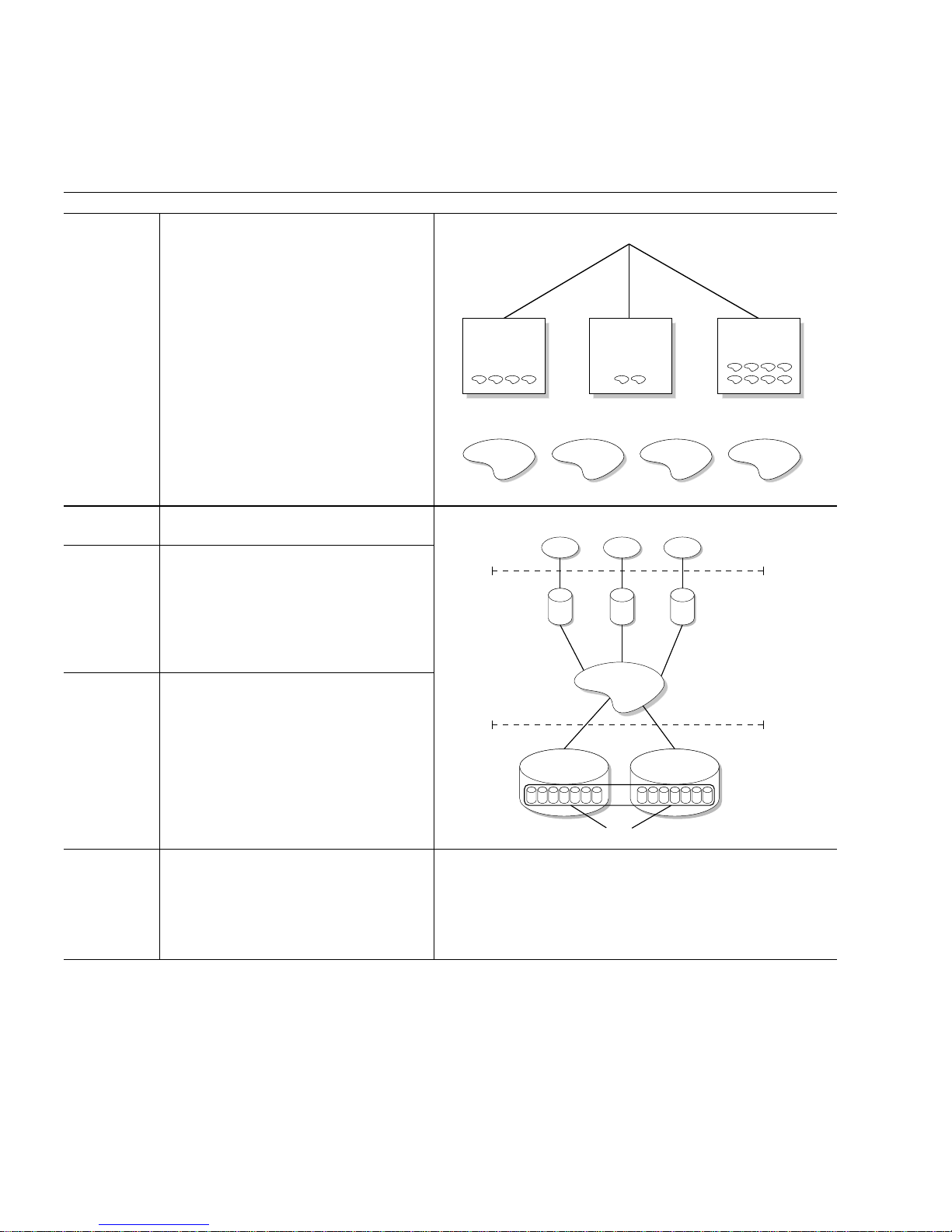
Logical Components
Storage
domains
Storage domains provide secure sharing
of storage resources. Storage domains
allow you to organize multiple
departments or applications into a single
storage management infrastructure.
TABLE 3-3 Sun StorEdge 6920 Syste m Logical and Phy sical Components o f the System
Storage Domains
Volumes Volumes are created from storage pools
and presented to hosts as LUNs.
Storage
pools
A storage pool is associated with a
storage profile, which defines I/O
performance characteristics. The system
provides several storage profiles, or you
can create a custom profile. A storage
pool can contain zero, one, or more
virtual disks.
Virtual disks A virtual disk is an abstraction of storage
created from a set of physical disks. The
storage array presents the virtual disk to
the system. You can have a maximum of
two virtual disks per storage tray.
Finance Engineering
Domains
Random I/O Mail Space File Serving Sequential
Pools
Storage Domain
Storage Pools
Virtual Disks
Sales
Initiators
Volumes
Snapshots A snapshot is a point-in-time copy of a
primary volume. The snapshot can be
mounted by an application and used for
backup, application testing, or data
mining without taking the primary volume
offline.
58 Sun StorEdge 6920 System Getting Started Guide • May 2004
Storage Tray
Disks
Page 77
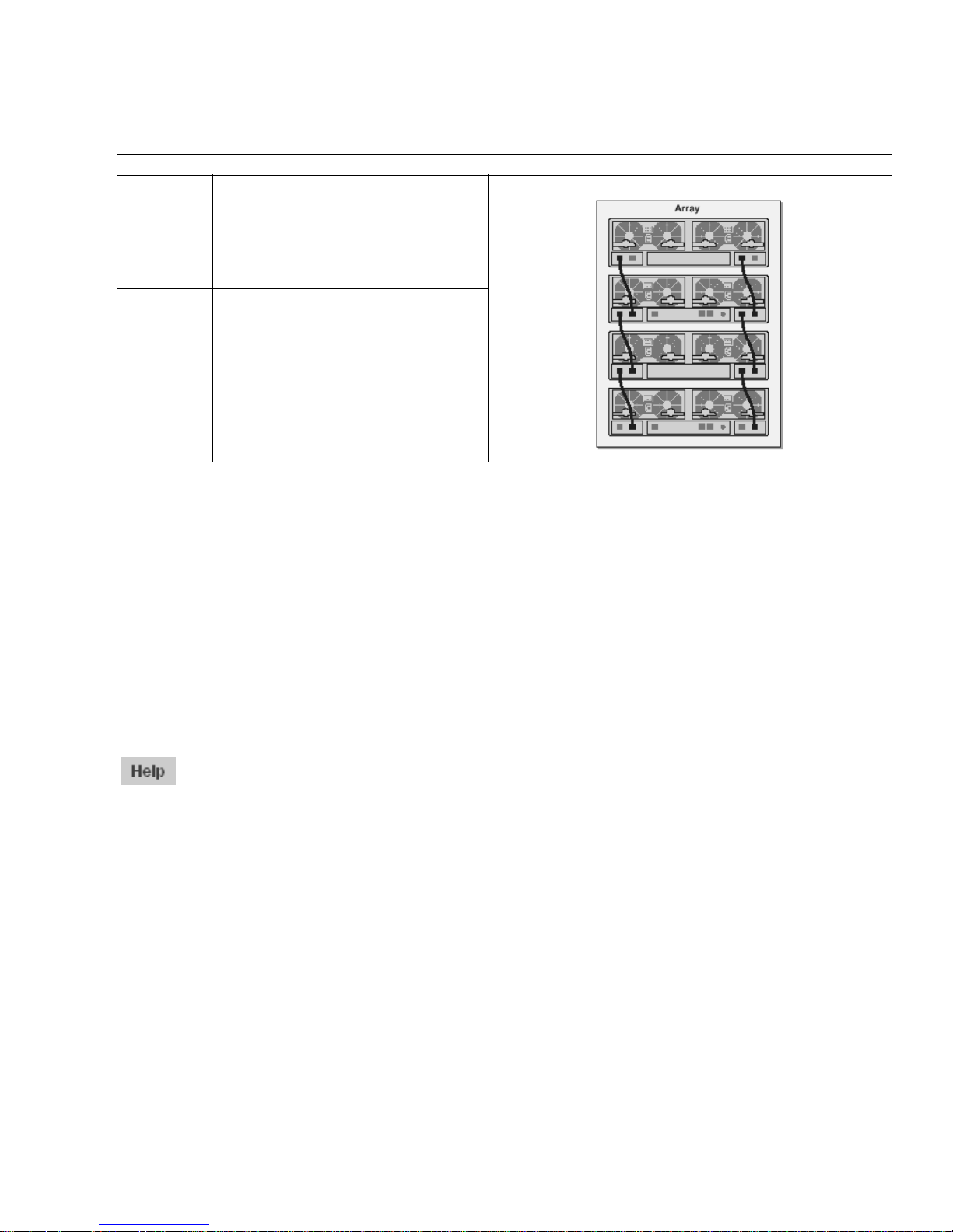
TABLE 3-3 Sun StorEdge 6920 Syste m Logical and Phy sical Components of the System
Physical Components
Storage
arrays
Storage
trays
Disks A disk is a non-volatile, randomly
A storage array includes two controllers
(also referred to as a controller pair) to
provide redundancy and failover
capabilities.
Storage trays can contain from seven to
fourteen disk drives each.
addressable, rewriteable data storage
device. A tray can contain from seven to
fourteen disks.
What Is a Storage Domain?
Storage domains are “containers” of physical and logical storage elements managed
by the system. When you create a storage domain, you create a functional virtual
network that is scalable and secure.
The user sees only the logical network that the storage domain creates. The storage
administrator sees all the storage elements available on the system, organizes them
according to need, assigns them different attributes, and creates data services that
will deliver data from one end of the network to the other (from storage device to
the host). Each storage domain is uniquely named and cannot be shared among
different clients.
For more information about the storage domains, go to the online help system by
clicking the Help button. Click the Search tab and type storage domains.
Storage Domain Provisioning Considerations
To determine how to configure your system, you have to decide how you want to
use it, depending on your needs and the needs of your users. Do you want to use the
default configuration as is, with only one storage domain, or divide the system into
multiple smaller, but fully functioning, private, secure storage domains?
These storage domains create separate private, logical networks that can support
multiple clients within one Sun StorEdge 6920 system.
The system is provisioned with one storage domain called DEFAULT. This storage
domain contains the Default storage pool with its assoc iated disks and virtual disks.
Chapter 3 Configuring the System 59
Page 78

When you configure storage domains, you can do either of the following:
■ Use the existing default configuration (as is)
■ Create a custom storage domain
You can have from 1 to 64 storage domains.
What Is a Storage Profile?
A storage profile enables you to apply a predetermined set of characteristics to a
storage pool at one time, instead of having to apply each characteristic individually.
Each storage profile contains storage performance characteristics such as the RAID
level, segment size, dedicated hot spare, and virtualization strategy.
The default configuration uses the storage profile “Default” with the following
parameters:
■ Array Segment Size: 64 Kbyt es
■ Array Read-Ahead Mode: On
■ RAID Level: RAID-5
■ Array Type: Best Match Bandwidth
■ Number of Disks: Variable
■ Dedicated Hot Spare: No
■ Virtualization Strategy: Stripe
■ Stripe Size: 1 Mbyte
Note – You ca nnot delete or modify the Default profile, and you cannot delete or
modify a profile that is in use and associated with a storage pool.
For more information about storage profiles and their characteristics, go to the
online help system by clicking the Help button. Click the Search tab and type
storage prof iles.
Deciding Which Storage Profile to Use
The virtualization strategy is associated with a storage profile. You can choose
between two virtualization strategies:
■ Concatenation
■ Striping
60 Sun StorEdge 6920 System Getting Started Guide • May 2004
Page 79

In a concatenated volume, virtual disk partitions are filled with data sequentially,
with the sec ond disk bein g written to when no sp ace remains on th e first, the third
when no room remains on the second, and so on. The system di stributes the volume
space across devices by using the devic es with the smalles t amount of available
space first.
In a striped volume, the system divides data int o blocks and distributes (or stripes)
the data blocks even ly a cross sever al disk blocks. The system dist ributes the v olume
space across devices e qually by using the sm allest number of devices possible to
make a volume of the desired size. Striping distributes (reads and writes) data to
two or more slices that reside on different disks.
A concatenated volume does not have the enhanced performance of a striped
volume. In a concat enat ed volum e the sy st em wr ite s a sing le bl ock to a si ng le virt ual
disk. In a striped volume, each b lock is divided, and port ions of the data are written
to different disks simultaneously. Striping data improves your disk performance
because it performs simultaneous disk read/write operations on multiple disks.
You can choose any of the following options:
■ Use the default storage profile with the existing default configuration (as is)
■ Select one of the predefined storage profiles shipped with the system
■ Create a custom storage profile
For more information about virtualization strategies, go to the online help system by
clicking the Help button. Click the Search tab and type concatenated or
striped.
What Is a Volume?
Volumes are “containers” into which applications, databases, and file systems can
put data. A volume can be a physical disk or a virtual disk mapped from one or
more extents. (An extent is a set of disk blocks with logical consecutive addresses.)
The default storage configuration defines one domain with a single storage pool that
uses a default p rofile. To use your stor age efficiently, you must create volumes from
a storage pool that is associated with a storage profile.
For more information about volumes, go to the online help system by clicking the
Help button. Click the Search tab and type volumes.
What Is a Storage Pool?
Storage pools are collections of virtual disks with the same configuration and
performance characteristics. A storage pool can contain zero, one, or more virtual
disks. You manage the system’ s virtual disks as a pool of storage spac e. By using
Chapter 3 Configuring the System 61
Page 80

virtual disks instead of physical disk partitions, you can reconfigure disk storage
while the system is active (online). You do not need to stop storage input and output
(I/O) activity, shut down the system, or back up and restore data.
Storage Pool Provisioning Co nsiderations
In the default configuration, there is one storage domain (DEFAULT) and one
storage pool (Default), which uses a default storage profile. The Default storage pool
contains all vi rtua l disks i n the system . If you do not wan t to use the D efault stora ge
pool, you can create a new storage pool.
There are two options to choose between when configuring storage pools:
■ Use the existing default configuration (as is)
■ Create a new storage pool
For more information about storage pools, go to the online help system by clicking
the Help butt on. Click th e Search tab and type storage po ols.
What Is a Virtual Disk?
A virtual disk a collection of disks or a set of contiguous disk blocks that are
grouped according to RAID levels. The maximum number of virtual disks per
storage tray is two.
Virtual disks are partitioned into volumes and appear to applications, databases, and
file systems as physical disks. Th erefore, you can allocate storage on virtual di sks the
same way you allocate storage on othe r disk devices.
Virtual Disk Provisioning Considerations
In the default configuration, all virtual disks are available to be added to either the
Default storage pool or a custom-created pool.
When configuring storage pools, you can:
■ Use the existing default configuration (as is)
■ Move the default RAID-5 virtual disks to a new pool
■ Delete the RAID-5 virtual disk and create a different virtual disk in a new pool
For more information about virtual disks and RAID levels, go to the online help
system by clicking the Help button. Click the Search tab and type virtual disks.
62 Sun StorEdge 6920 System Getting Started Guide • May 2004
Page 81

What Is a Snapshot?
The Sun StorEdge Data Snapshot software allows you to make non-disruptive pointin-time copi es of a volume’ s data. The sna pshot image can then be mou nted to
another server, enabling the primary volume to continue servicing the application.
Each snapshot can be accessed independently by other applications. For example, a
snapshot can be mounted on a backup server, which will back up the data to tape.
A snapshot is a copy of the dat a on a volume at the moment th at you create the
snapshot. This sn apshot implem entati on uses t he c opy-on-w rite, or de penden t copy,
technolog y. Fo r detailed informati on about the snapshot tec hnology, see the online
help.
Note – A snapshot of data is not suitable for failure recovery. You should continue
to use offline backup methods to create full-volume backup copies of your data.
The system stores snap shots i n a n area on th e pri mary vol ume call ed snapshot reserve
space. The snapsh ot reserve space is configu red to take data from a primary volume
(the application’s volume) and store up to eight snapshots and associated metadata.
Snapshot Plan ning Considerat ions
Before you can create a snapshot, the volume must have snapshot reserve space. You
can allocate the snapshot reser ve space when you first create th e volume or w hen
you first request a snapshot of the volume. In either case, the New Snapshot wizard
guides you through the process.
After you allocate the snapshot reserve space, you cannot modify it, so it is
important to choose th e proper size. The advantage to allocating the snaps hot
reserve space a t the time you c reate the volume is that you ca n be sure there is
sufficient free space for the snapshots. When you allocate the snapshot reserve space
at a later time, the amount of free space you need might not be available. If you do
not allocate enough snapshot reserve space, you risk running out of storage space
before a snapshot can be compl eted, thereby corrupting the sn apshot data and
making previous snaph ots unusable. In addi tion, if the snapshot reserve space you
created is too small, you must delete existing snapshots as required to make space
for new ones.
The proper size of the snapshot reserve space depe nds on the following factors:
■ The number of snapshots to be taken
The more snapshots you take, t he m ore space i s required for t he sn apshot reserve
space. Specify the size of the snapshot reserve space as a percentage of the
primary volume. Depending on the number of snapshots you want, specify from
1% to 800% of the primary volume’s si ze.
Chapter 3 Configuring the System 63
Page 82

■ The degree of write activity anticipated on the primary volume
Write activ ity is the num ber of writ e operatio ns that occ ur on the prim ary
volume. It se rves as a measure of the net chang e in that prima ry volume over
time. To determine the total space required for snapshot reserve space, specify the
percentage of anticipated c hange to the primary volum e (10% to 100%) between
snapshots.
■ The length of time you expect to keep a snapshot
After you take a snapshot, subsequent changes to the primary volume’s data are
saved in the snapsh ot reserve space. The longer a sn apshot remains in existen ce,
the larger the amount of snapshot reserve space is required.
■ The degree of write activity anticipated on the snapshot
The snapshot can be treated like a volume so you can mount it on a server and
make it available to another application. Some applications change data or set a
counter bit so that the snapshot itself is modified, making it different from the
data that is on the primary volume. These modifications are also stored in the
snapshot reserve space as well.
Snapshot space is consumed when a block is written to the primary volume that
hadn't been written to since the snapshot was created, and when a block is written to
the snapshot volume for the first time.
When you run the New Snap shot w izard, it is recomme nde d that yo u spec ify a writ e
activity level of 100%. Once a snapshot volume has been filled up, subsequent reads
and writes to the snapshot volume are rejected, so the snapshot no longer reflects
changes to the primary volume. Therefore, if you do not specify a high enough level
of write activity, your snapshots become invalid. Specifying a write activity level of
100% should allow for every block in the primary volume to chang e and for each of
those changes to be written to the snapshot volume.
As mentioned, t he amount of space the system allocates for snapshot rese rve space is
a function of the number of snapshots you anticipate taking, as well as of the write
activity level you specify. Suppose you have a 100 Gbyte primary volume. If in the
New Snapshot wizard you specify a snapshot number of 1 and a write activity level
of 100%, the system will allocate 107 Gbytes as snapshot reserve space; in contrast, if
you specify a snapshot number of 8 and a write activity level of 100%, the system
will allocate 856 Gbyte s of snapshot reserve space.
For more information about snapshots, go to the online help system by clicking the
Help button. Click the Search tab and type snapshots.
64 Sun StorEdge 6920 System Getting Started Guide • May 2004
Page 83

About the Def ault Configuration
The system ships from the factory with a default configuration, consisting of:
■ Storage domain “DEFAULT” – All storage elements are in one storage dom ain
(DEFAULT), which can be accessed by all hosts (initiators).
■ Storage pool “Default”– All virtual disks can be added to this st orage pool.
■ Storage profile “D efa ult ” – Th e DE FAULT storage doma in us es the D e fau lt pro fi le
to specify its storage param eters. There are also several additiona l profiles
provided with the system from which you can choose.
■ Virtual disks – Depending on the number of drives available, the system is
preconfigured as one RAID-5 virtual disk (7 drives) or two RAID-5 virtual disks
(14 drives).
Note – The default configuration does not include volumes. To use the default
configuration “as is,” you must configure volumes. For more information, see
“Storage Allocation Consider ations” on pag e 65 and “Creating Volumes” on page 67.
Storage Allocation Considerations
As you review your provisioning options and determine how to allocate storage
appropriately for your site, consider the following:
■ Your site’s security requirements – By creating multiple storage domains, you
segregate i nitiato rs. For exa mple, yo u can have ho sts that handle fi nancial da ta
store their data in a different domain tha n hosts that hand le research data.
■ Your site’s I/O requirements – The default configuration uses the Default storage
profile, with balanced access to storage. Depending on your needs, you can
optimize I/O activity by selecting a storage profile with different characteristics
or by creating a custom profile.
■ Your site’s performance requirements – In general, the number of host ports is
equal to the number of storage ports. You can add more hosts, but performance
declines if you don’t also add also add ports. You can expand the number of ports
by adding storage resource card (SRC) sets, up to a maximum of four.
Chapter 3 Configuring the System 65
Page 84

Provisioning Storage Using the Default
Configuration
This section describes the procedures for provisioning the system using the default
configuration. The fi rst step, “Creating Volumes” on page 67, must be done before
you can complete the provisioning process.
If you decide to con figure the system us ing the defaul t configuratio n, you must
create volumes within a storage pool and then assign each initiator in your
environment to one of the volumes. The system provides two wizards to assist you,
the New Volume wiza rd and the Vo lume-Initi ators Mappi ng wizard.
The wizards guide you throug h the steps to create and ma p a new volume:
■ Selecting a storage pool from which to create the volume
■ Specifying th e name and des cription o f the new volu me
■ Selecting a storage pool
■ Reserving space for a snap shot
■ Determining the capacity of the volume
■ Mapping initiators to the volume
For more information about the New Volume wizard, go to the online help system
by clicking the Help button. Click the Search tab and type creating a volume .
Viewing the Default Configuration
Settings
After you comp lete the ini tial conf iguratio n procedures, you c an review the set tings
of the Sun StorEdge 6920 sy stem.
Note – You must log in as the storage user to modify th e defa ult se ttin gs. You can
log in as admin or guest if you want to only view the configuration.
1. Log in to the system as a storage administrator from the Sun Web Console login
page:
user name: storage password: !storage
2. Click SE 6920 Configuration Service.
66 Sun StorEdge 6920 System Getting Started Guide • May 2004
Page 85

3. To review the storage doma ins configur ed on the system, click Storag e > Domains .
The system displays the Storage Domain Summary page.
4. To review the storage pools configured on the system, click Storage > Logical >
Pools.
The system displays the Storage Pool Summary page.
5. To review the virtual disks configured on the system, click Storage > Logical >
Virtual Disks.
The system displays the Virtual Disk Summary page.
6. To log out of the system, click Log Out.
Creating Volumes
Before you start to create volume s, be sure you understand t he system storage
concepts described in “Provisioning Storage” on page 57.
1. Log in to the system as a storage administrator from the Sun Web Console login
page:
user name: storage password:!storage
2. Click SE6920 Configuration Service.
The system displays the Volume Summary Page.
3. Click New.
Chapter 3 Configuring the System 67
Page 86
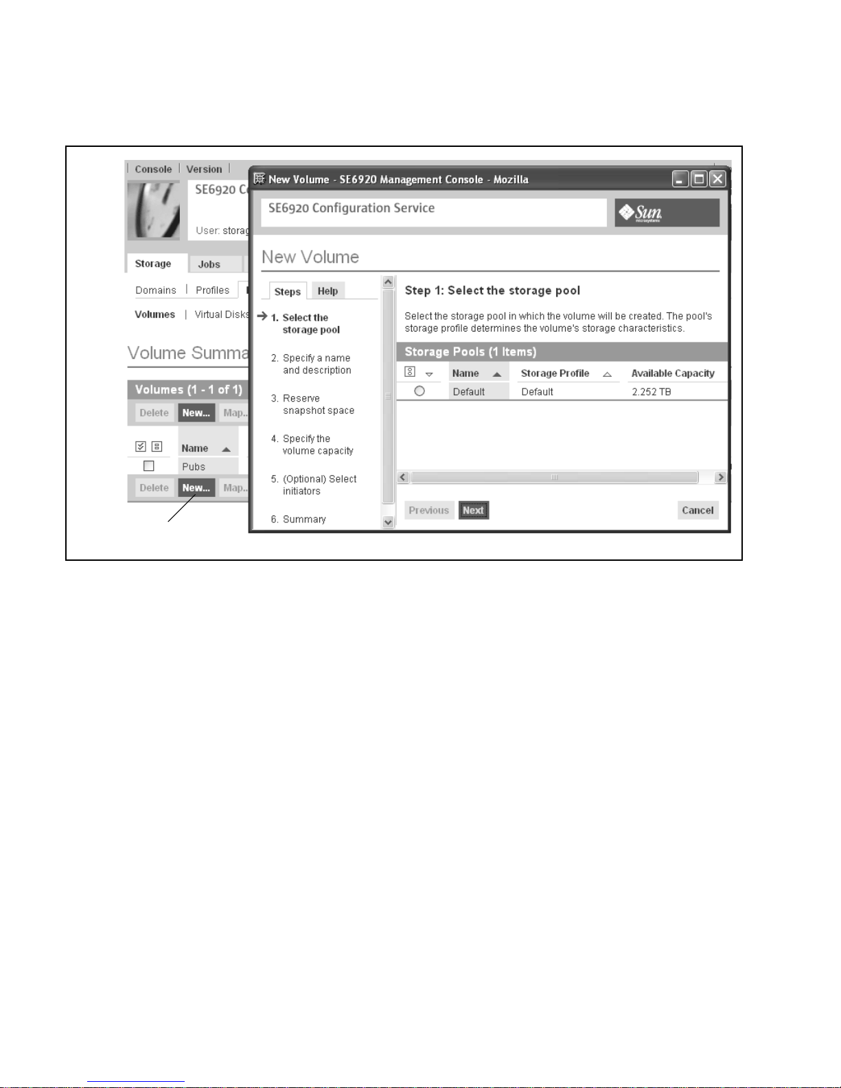
Click
New
button
The system displays the New Volume wizard (FIGURE 3-9).
FIGURE 3-9 Example: New Volume Wizard
68 Sun StorEdge 6920 System Getting Started Guide • May 2004
Page 87

4. Select a storage pool from which you want to create the volume. Click Next.
The storage profile of the pool you select determines the volume’s storage
characteristics.
5. Specify a name and a description for the new volume. Click Nex t.
Click the Help tab for a list of valid characters you can use when naming a new
volume name and specifying a description.
6. If needed, reserve snapsh ot space for the new volume. Click Next .
The snapshot reserve space is determined by the number of snapshots and the write
activity. Enter the number of snaps hots (between 1 to 8) an d the percentage of writ e
activity (between 10% and 100%). For more information about sn apshot reserve
space, see “What Is a Sn apshot?” on page 63.
7. Specify the volume capacity, and click Next.
The volume capacity plus the reserved snapshot space equals the amount of virtual
disk space used.
8. Optionally, select any initiators that you want to map to the volume, specify the
LUN number and permissions for each mapping, and click Next.
The system uses the LUN mapping storage management technique to selectively
configure an area of storage so that it is available to a specific Fibre Channel (FC)
device. LUN mapping matches FC targets or initiators inside the Sun StorEdge 6920
system to particular LUNs attached to the system, either directly attached or
attached to a SAN. Th is technique makes a given LUN visible to a FC t arget or
initiator while at the same time removing its visibility (or masking it) from another
FC target or initiator.
9. Review your selections for the new volume and click Finish.
The system creates the new volume and adds it to the system configuration. The
new volume is displayed in the list on the Volume summary page.
10. To log out of the system, click Log Out.
For more information about creating volumes, go to the online help system by
clicking the Help button. Click the Search tab and type creating a volume .
Common Storage Configuration Tasks
This section covers the following common storage configuration tasks:
■ “Creating a Storage Pool” on page 70
■ “Adding Storage to a Pool” on page 70
Chapter 3 Configuring the System 69
Page 88

■ “Creating a Storage Domain” on page 71
■ “Creating a Storage Profile” on page 71
Creating a Storage Pool
1. Log in to the system as a storage administrator from the Sun Web Console login
page:
user name: storage password:!storage
2. Click SE6920 Configuration Service.
The system displays the Volume Summary page.
3. Click Storage > Logical > Pools.
The system displays the Storage Pool Summary page.
4. Click New.
The system displays the New Storage Pool wizard.
5. Select the Storage Domain into which you want to add a new storage pool, and
click Next.
6. Complete the remaining wizard steps as instructed.
For more information about creating storage pools, go to the online help system by
clicking the Help button. Click the Search tab and type creating a storage
pool.
Adding Storage to a Pool
1. Log in to the system as a storage administrator from the Sun Web Console login
page:
user name: storage password:!storage
2. Click SE6920 Configuration Service.
The system displays the Volume Summary page.
3. Click Storage > Logical > Pools.
4. Click the name of the storage pool to which you want to add storage.
The system displays the Storage Pool Details page.
5. Click Add Storage.
70 Sun StorEdge 6920 System Getting Started Guide • May 2004
Page 89

The system displays the Add Storage wizard.
6. Complete the wizard steps as instructed.
For more information about adding storage to a pool, go to the online help system
by clicking the Help button. Click the Search tab and type add storage.
Creating a Storage Domain
1. Log in to the system as a storage administrator from the Sun Web Console login
page:
user name: storage password:!storage
2. Click SE6920 Configuration Service.
The system displays the Volume Summary page.
3. Click Storage > Domains.
The system displays the Storage Domain Summary page.
4. Click New.
The system displays the New Storage Domain wizard.
5. Complete the wizard steps as instructed.
For more information about creating a storage domain, go to the online help system
by clicking the Help button. Click the Search tab and type create a storage
domain.
Creating a Storage Profile
1. Log in to the system as a storage administrator from the Sun Web Console login
page:
user name: storage password:!storage
2. Click SE6920 Configuration Service.
The system displays the Volume Summary page.
3. Click Storage > Profiles.
The system displays the Storage Profile Summary page.
4. Click New.
The system displays the New Storage Profile wizard.
Chapter 3 Configuring the System 71
Page 90

5. Complete the wizard steps as instructed.
For more information about creating a storage profile, go to the online help system
by clicking the Help button. Click the Search tab and type create a storage
profile.
72 Sun StorEdge 6920 System Getting Started Guide • May 2004
Page 91

At a Glance:
What Are the Key Benefits?
Configuring
the System
This chapter provides procedures for configuring a newly installed Sun
StorEdge 6920 system.
The system is shipped with a defau lt configuration which simplifies
storage provisioning. The central point of configuration and
management makes it easy to configure volumes. The software
automatically discovers servers attached to the system and makes them
readily accessible.
What Are the Steps?
The basic software configuration steps for the Sun StorEdge 6920
system are:
1. Establi sh the initial
through the serial connection and running the setup script.
2. Complete the initial configuration steps:
• Configure system-wide settings.
• Configure diagnostics and monitoring settings.
3. Log in to the system to become familiar with GUI and review
the default configuration.
configuration by logging in to the system
SSCS
4. Plan for and provision storage at yo u r site.
For More Information
For detailed information about procedures in this chap ter, open the
online help system by clicking the Help butto n. Click the Search tab,
type one of the following entries in the Search text box, and then click
Go.
• provisioning storage
• creating volumes
• volume snapshots
For detailed information about related CLI comma nds, a ccess the CLI
and then type the following subcommand with the help option. For
example:
> sscs create -help
Chapter 3 Configuring the System 73
Page 92

74 Sun StorEdge 6920 System Getting Started Guide • May 2004
Page 93

APPENDIX
A
Remote Response Service
This appendix provides information about the Sun StorEdge Remote Response
service. It contains the following sections:
■ “Supported Country Listing” on page 75
■ “Remote Res ponse Servic e Worksheet” on page 76
■ “Connecting Multiple Systems” on page 77
Supported Country Listing
Following is a list of countries in which the Sun StorEdge Remo te Response servi ce is
supported. If the country in which you are located is not listed below, contact Sun or
a licensed Sun reseller or service provider for assistance in setting up and activating
the Sun StorEdge Remot e Response service.
Supported countries are: Argentina, Australia, Austria, Belgium, Brazil, Bulgaria,
Canada, China, Czech Republic, Denmark, Finland, France, Germany, Greece,
Hungary, Iceland, India, Ireland, Italy, Japan, Malaysia, Mexico, The Netherlands,
New Zealand, N orway, Philippines, Poland, Port ugal, Roman ia, Russia, Singapore,
South Africa, South Korea, Spain , Sweden, Switzerland, Taiw an, Thailand, Turkey,
U.K., and U.S.A.
75
Page 94

Remote Response Service Worksheet
Before you call Sun to request service activation, gather the information listed in
TABLE A-1. You should retain this information for future reference.
TABLE A-1 Sun StorEdge Remote Response Service Worksheet
Requirement Information
Company name
Site address
Site state or province
Site country
Name o f the c ontac t pers on at t he
site
Telephone number of the contact
person at the site
Telephone number of the
dedicated analog telephone line
Information about the
configuration of the system at the
site. For example, is there a
firewall between the console and
the system?
Are there additional Sun StorEdge
6920 or 6320 systems sharing the
dedicated phone line?
How is the storage configured?
How many and what types of
hosts will be connected to the Sun
StorEdge 6920 system?
Serial numbers of all Sun StorEdge
6920 and 6320 systems at the site
76 Sun StorEdge 6920 System Getting Started Guide • May 2004
Page 95

Connecting Multiple Systems
If multiple Sun StorEdge 69 20 systems are inst alled at your sit e, you can conn ect the
systems in a ch ain to share a sing le tel ephone li ne. A max imum of eight syste ms can
be connecte d togethe r to communic ate with the Sun Service Center.
Note – It is i mportant th at you co nnect the Storage Serv ice Processor t o the St orage
Service Processor LAN before configuring the system.
Connecting multiple systems to share a telephone line requires the following:
■ The first system con taining the modem must be installed and co nfigured with a
system ID of 0.
■ The telephone line must be connected to the service panel of the first base cabinet.
Note – There can only be one new_sp (the default system name) on the Storage
Service Processor LAN at any one time. Therefore, you must connect the Storage
Service Processor LAN ports, run setup, and give the system a unique system ID for
each system in the chain before connecting the next system.
Before you begin this procedure, contact your local Sun Service Center to request
Sun StorEdge Remote Response installation service.
To connect a Sun StorEdge 6920 sy stem to another system:
1. Connect the SP LAN OUT port on the service panel of the base cabinet to the SP
LAN IN port of the adjacent system.
2. Run setup as described in “Running the Initial Configuration Script” on
page 3-3 8.
Be sure to give each sys tem in the chain a un ique system ID.
3. Contact your local Sun Service Center and ask for Sun StorEdge Remote Response
service activation.
4. If you want to connect another system, repeat the previous steps unti l each system
in the chain is connected.
For information about connec ting the Sun StorEdge 6920 syst em to a Sun StorEdge
6320 system, cont act the Sun Service Center.
Appendix A Remote Response Service 77
Page 96

78 Sun StorEdge 6920 System Getting Started Guide • May 2004
Page 97

APPENDIX
B
Remote and Local Power
Management
This appendi x describes how to enabl e remote power manageme nt for the Sun
StorEdge 6920 system. It includes the following sections:
■ “Preparing the System for Remote Power” on page 80
■ “Performing a Partial System Shutdown” on page 91
■ “Performing a Full System Shutdown” on page 93
■ “Restoring Power to the System” on page 96
When th e remot e po wer-on and p ower-o ff feat ure is e nable d, th e con figur ation
management GUI allows y ou to perform a partial system shutdown from a remote
location. When the system is in the partial shutdown state, the Storage Service
Processor and the Storage Service Processor accessory tray remain powered on and
active, to facilitate a future remote power-on operation.
Caution – Do not use th e partial remote po wer-off sequence wh en moving the
system. You must completely power off the system, as de scribed in “Performing a
Full System Shutdown” on page 93, before moving it.
Note – If you are installing a Sun StorEdge 6920 system with an expansion cabinet,
perform the procedures in this appendix for both cabinets.
79
Page 98

TABLE B-1 lists the field-replaceable units (FRUs) required to perform the tasks in this
appendix.
TABLE B-1 Power Cable—FRU List
Quantity FRU Description Part Number
2 Power cable for 72-in. (185-centimeter) Sun StorEdge
cabinet (U.S./Canada), L6-30P
2 Power cable for 72 in. (185 cm) Sun StorEdge expansio n
cabinet (International), IEC 309
1 78.74 in. (2-meter) grounding cable (in the kit shipped with
the system)
2 393.7 in. (10-meter) expansion cabinet DB9 to base cabinet
DB9 cable (if needed)
595-4881-nn
595-4882-nn
530-1619-nn
530-3210-nn
The following tools are required to perform the tasks in this appendix:
■ Keys for key switch (in th e kit shipped with the system)
■ Phillips screwdriver
Preparing the System for Remote Power
The information in this sec tion assumes you are inst alling the Sun StorEdge 69 20
system for the firs t time a nd have not yet powered on the syst em.
Note – If you want to enable remote power management for a system that is
operational, you must first perform a full system shutdown, as described in
“Performing a Full System Shutdown” on page 93. After shu tting down t he system,
you can enable the system for remote power management by completing the
following steps.
1. Verify that the key switches located at the bottom front of the base cabinet and
any expansion cabinet are in the Standby position (
Keys for this switch are packed in the kit that was shipped with the base cabinet and
expansion cabinet (if applicable). If the key switch is not in the Standby position,
insert the key and turn the key switch to Standby.
80 Sun StorEdge 6920 System Getting Started Guide • May 2004
FIGURE B-1).
Page 99
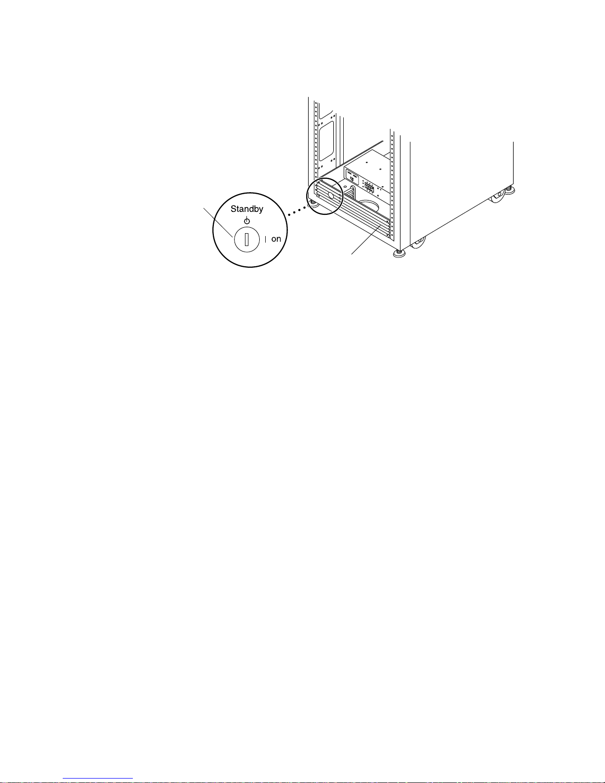
Key switch
in Standby
position
Front trim panel
FIGURE B-1 Location of Key Switch on Bottom Front Panel (Standby Positio n)
2. Open the front door and the back door of the base cabinet.
3. At the bottom on the base cabinet, loosen the four screws on the front trim panel
and remove the panel.
Set the panel aside .
4. Verify that both power sequencer cir cuit breakers in the base cabinet and
expansion cabinet (if appl icable) are in the Off position.
5. At the back of the base cabinet, loosen the four screws holding the right side of
the service panel and swing the panel open.
Appendix B Remote and Local Power Management 81
Page 100
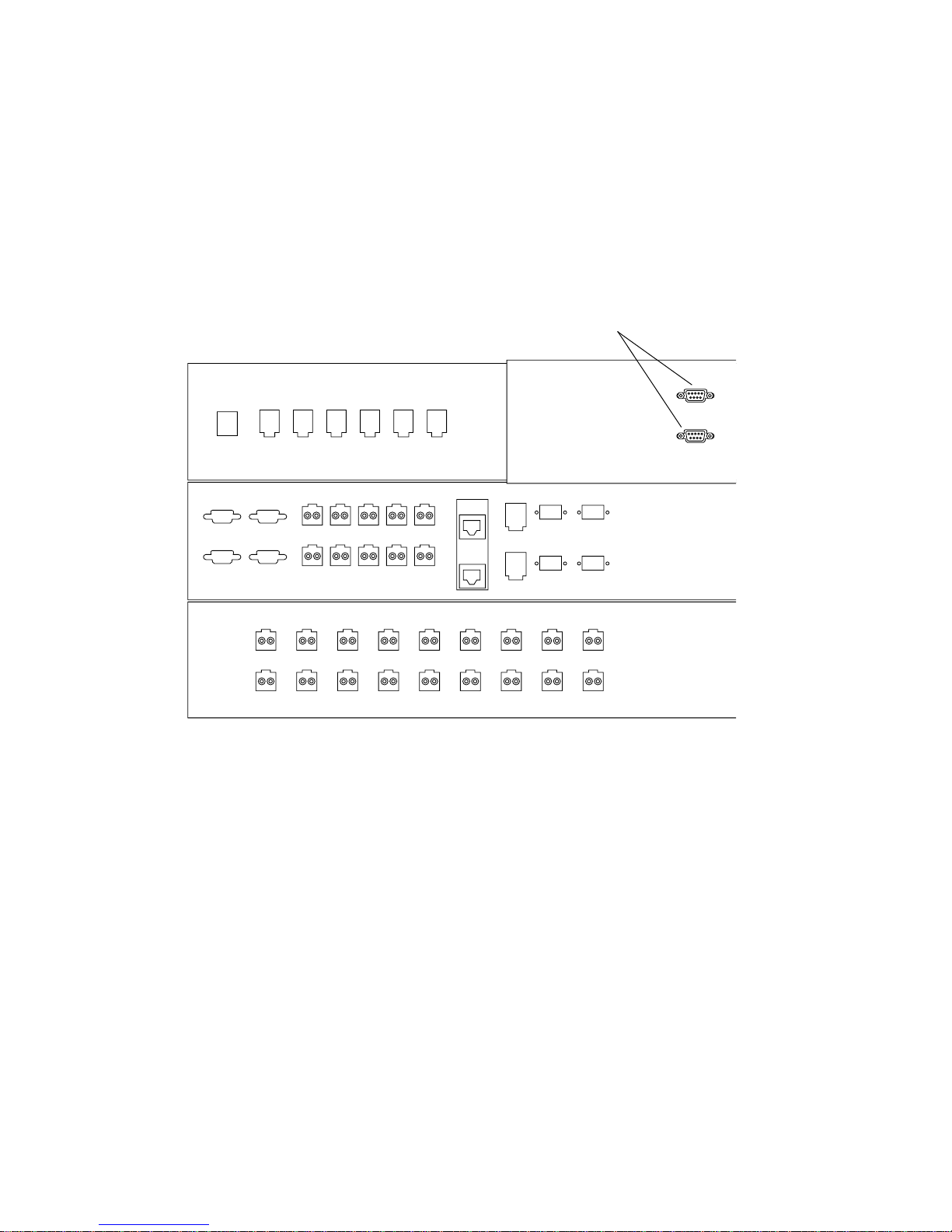
6. Locate the two DB9 cables that are loosely tied off close to the relay panel on the
back of the service panel. Connect the cable labe led “J14 to PP Front Seq J14 In” to
the FRONT SEQ J14 connection a nd the cable labeled “J14 to PP Rear Seq J14 In”
to the REAR SEQ J14 connection on the back of the service panel (
FIGURE B-2).
The other e nds of thes e cables are al ready connec ted to the front and rear po wer
sequencers.
These cables enable the Storage Service Processor to recognize that the system is
capable of a remote power-on and power-off sequence.
DB9 Cables
FRONT SEQ J14
RELAY IN
FIGURE B-2 Connections for the Front and Rear Power Sequ encers on the Inside of the
REAR SEQ J14
Base Cabinet Servi ce Panel
7. Close the service panel and tighten the four screws.
8. If an expansion cabinet is includ ed in the system, use the two 393.7-inch (10 meter) DB9-to-DB9 expansion cabinet cables to connect the power sequencer
control cables between the power sequencer output jacks on the front of the base
service panel to the power sequencer input jacks on the front of the expansion
cabinet service panel for both the front and rear power sequencers.
The cables are in the kit that was shipped with the system.
This connection allows the expansion cabinet to power on or power off when the
base cabinet is powered on or powered off.
The power input and output jacks on the service panel are shown in
82 Sun StorEdge 6920 System Getting Started Guide • May 2004
FIGURE B-3.
 Loading...