

Page 1

Sun StorEdge™3900 and 6900
Series Reference Manual
Alpha Draft
Sun Microsystems, Inc.
4150 Network Circle
Santa Clara, CA 95054 U.S.A.
650-960-1300
Part No. 816-3245-10
February 2002, Revision A
Send comments about this document to: [email protected]
Page 2

Copyright 2002Sun Microsystems, Inc.,4150 networkSCircle, SantaClara, CA95054 U.S.A.All rightsreserved.
This product ordocument isdistributed underlicenses restrictingits use,copying, distribution,and decompilation.No partof thisproduct or
document may be reproduced inany formby anymeans withoutprior writtenauthorization ofSun andits licensors,if any.Third-party
software,including fonttechnology,is copyrightedand licensedfromSun suppliers.
Parts of the product maybe derivedfrom BerkeleyBSD systems,licensed fromthe Universityof California.UNIX isa registeredtrademark in
the U.S. and other countries, exclusively licensed through X/OpenCompany,Ltd.
Sun, Sun Microsystems,the Sunlogo, AnswerBook2,Sun StorEdge,StorTools,docs.sun.com, SunEnterprise, SunFire, SunOS, Netra, and
Solaris are trademarks,registered trademarks,or servicemarks ofSun Microsystems,Inc.in theU.S. andother countries.All SPARC
trademarks are usedunder licenseand aretrademarks orregisteredtrademarks ofSPARCInternational, Inc.in theU.S. and other countries.
Productsbearing SPARCtrademarks arebased uponan architecture developed by Sun Microsystems,Inc.
The OPEN LOOK and Sun™ Graphical User Interface was developed bySun Microsystems,Inc. forits usersand licensees.Sun acknowledges
the pioneering effortsof Xeroxin researchingand developing the concept of visual orgraphical userinterfaces forthe computerindustry.Sun
holds a non-exclusive license fromXerox tothe XeroxGraphical UserInterface, whichlicense alsocovers Sun’s licensees who implement OPEN
LOOK GUIs and otherwise comply with Sun’s written license agreements.
Federal Acquisitions: CommercialSoftware—Government UsersSubject toStandard LicenseTerms and Conditions.
DOCUMENTATION IS PROVIDED “AS IS” AND ALL EXPRESS OR IMPLIED CONDITIONS, REPRESENTATIONS AND WARRANTIES,
INCLUDING ANYIMPLIED WARRANTYOF MERCHANTABILITY,FITNESS FORA PARTICULARPURPOSE ORNON-INFRINGEMENT,
ARE DISCLAIMED, EXCEPT TO THE EXTENT THAT SUCH DISCLAIMERS ARE HELD TO BE LEGALLY INVALID.
Copyright 2002 Sun Microsystems, Inc.,4150 networkSCircle, SantaClara, CA95054 Etats-Unis.Tousdroitsréservés.
Ce produit oudocument estdistribué avecdes licencesqui enrestreignent l’utilisation,la copie,la distribution,et la décompilation. Aucune
partie de ce produit oudocument nepeut êtrereproduitesous aucuneforme, parquelque moyenque cesoit, sansl’autorisation préalableet
écrite de Sun et de ses bailleurs de licence, s’il y en a.Le logicieldétenu pardes tiers,et quicomprend latechnologie relativeaux policesde
caractères,est protégépar uncopyright etlicencié pardes fournisseursde Sun.
Des parties de ce produitpourront êtredérivées dessystèmes BerkeleyBSD licenciéspar l’Universitéde Californie.UNIX estune marque
déposée aux Etats-Unis et dans d’autres payset licenciéeexclusivement parX/Open Company,Ltd.
Sun, Sun Microsystems,le logoSun, AnswerBook2,Sun StorEdge,StorTools,docs.sun.com, SunEnterprise, SunFire, SunOS, Netra, et Solaris
sont des marquesde fabriqueou desmarques déposées,ou marquesde service,de SunMicrosystems,Inc. auxEtats-Unis etdans d’autrespays.
Toutesles marquesSPARCsont utiliséessous licenceet sontdes marquesde fabrique ou des marques déposées deSPARC International, Inc.
aux Etats-Unis et dans d’autrespays. Lesproduitsportant lesmarques SPARCsont baséssur unearchitecture développée par Sun
Microsystems,Inc.
L’interfaced’utilisation graphique OPEN LOOK et Sun™ a été développéepar SunMicrosystems, Inc.pour sesutilisateurs etlicenciés. Sun
reconnaîtles effortsde pionniersde Xeroxpour larechercheet ledéveloppement duconcept desinterfaces d’utilisationvisuelle ougraphique
pour l’industrie de l’informatique. Sun détient une licence non exclusive deXerox surl’interface d’utilisationgraphique Xerox,cette licence
couvrant également les licenciés de Sun qui mettent en place l’interfaced’utilisation graphiqueOPEN LOOKet quien outrese conformentaux
licences écrites de Sun.
LA DOCUMENTATIONEST FOURNIE “EN L’ETAT” ET TOUTES AUTRES CONDITIONS, DECLARATIONSET GARANTIES EXPRESSES
OU TACITES SONT FORMELLEMENTEXCLUES, DANSLA MESUREAUTORISEE PARLA LOIAPPLICABLE, YCOMPRIS NOTAMMENT
TOUTE GARANTIE IMPLICITE RELATIVE A LA QUALITE MARCHANDE, A L’APTITUDE A UNE UTILISATION PARTICULIERE OU A
L’ABSENCE DE CONTREFAÇON.
Please
Recycle
Page 3

Contents
Preface xiii
1. Introduction 1
Overview 1
Sun StorEdge 3910 System 3
Sun StorEdge 3960 System 4
Sun StorEdge 6910 System 5
Sun StorEdge 6960 System 6
Architecture 7
System-Level Support Information 9
Features 9
Sun StorEdge 3900 and 6900 Series Common Features 9
Sun StorEdge 3900 Series Features 11
Sun StorEdge 6900 Series Features 11
2. Component Descriptions 13
Hardware Component Descriptions 13
Storage Service Processor 13
Virtualization Engines 14
Customer-Management Connection 15
iii
Page 4

Storage Devices 15
Ethernet Hub 16
Fibre Channel Switches 16
Sun StorEdge Expansion Cabinet 16
Software Component Descriptions 17
Solaris 8 17
Sun StorEdge Remote Response 17
Configuration Utilities 18
Storage Automated Diagnostic Environment 18
Diagnostics 18
Storage Automated Diagnostic Environment Agent 19
Configuration User Interface 19
SANSurfer 21
Explorer Data Collection Utility 21
3. Default Configurations and Settings 23
Sun StorEdge 3900 and 6900 Series Layout 24
Virtualization Engine Settings 26
Sun StorEdge T3+ Array Settings 29
Sun StorEdge T3+ Array syslog.conf Configuration 32
Sun StorEdge Network FC Switch Settings 32
Ethernet Address Settings 37
4. Configuration Features 39
Standalone With No Remote Service 39
Multiple Units With No Remote Service 40
Remote Service to a Single Unit With No Host Connection 41
Remote Service to Multiple Units With No Host Connection 42
iv Sun StorEdge 3900 and 6900 Series Reference Manual • February 2002
Page 5

5. Configuration Utilities 45
Overview 45
Menu-Driven Interface 46
Sun StorEdge T3+ Array Main Menu 47
Sun StorEdge Network FC Switch Main Menu 54
Virtualization Engine Main Menu 60
View Log Option 73
View Errors Option 73
Command Line Interface 75
Storage Service Processor Global Commands 75
Storage Service Processor Sun StorEdge T3+ Array Commands 76
Storage Service Processor Switch Commands 77
Storage Service Processor Virtualization Engine Commands 78
6. Fault Detection and Isolation Overview 81
Monitoring 81
Fault Detection 82
Local Monitoring 82
Remote Monitoring 83
Fault Isolation 83
7. Storage Service Processor Software Setup Instructions 85
▼ To Make a Connection to the Storage Service Processor from an Onsite
System 86
▼ To Make a Connection to the Storage Service Processor from a Remote
System 86
▼ To Set the Host Name 87
▼ To Set the IP Address 90
▼ To Set the Date and Timezone 91
Contents v
Page 6

▼ To Verify the Configuration 91
▼ To Attach a Sun StorEdge 3900 or 6900 Series to a LAN 92
8. Sun StorEdge 3900 and 6900 Series Setup Instructions 93
Sun StorEdge 3900 and 6900 Series Setup 93
▼ To Configure a Sun StorEdge 3900 Series 93
▼ To Configure a Sun StorEdge 6900 Series 94
9. Repair and Replacement 97
Field Replaceable Units 97
▼ To Replace the Ethernet Hub 98
▼ To Replace a Sun StorEdge FC Switch 98
▼ To Replace a Sun StorEdge T3+ Array 99
Replacing the Storage Service Processor 101
▼ To Replace the Storage Service Processor With Remote Response
Installed 102
▼ To Replace the Storage Service Processor Without Remote Response
Installed 104
▼ To Service the Storage Service Processor 105
▼ To Replace a Virtualization Engine 106
10. Field Upgrades and Additions 111
▼ Adding a Cabinet in the Field 111
▼ Adding a Sun StorEdge T3+ Array 114
▼ To Upgrade the Sun StorEdge T3+ Array Firmware 116
▼ To Upgrade the Sun StorEdge FC Switch Firmware 117
▼ To Upgrade the Virtualization Engine Firmware 117
11. Connecting to Solaris Servers 119
▼ To Set Up a Solaris Server 119
vi Sun StorEdge 3900 and 6900 Series Reference Manual • February 2002
Page 7

▼ To Configure the ssd.conf File 122
▼ To Configure the Sun StorEdge Traffic Manager 124
▼ To Match the Host WWN to the Device Channel and Create SLIC Zones for
LUN Masking 125
▼ To Create VLUNs on the Sun StorEdge 6900 Series 128
▼ To Set Up Newly Created VLUNs 129
▼ To Set Up Multiple Zones and VLUNs Using a Script 130
▼ To Set Up VERITAS Volume Manager Support 134
▼ To Map VLUNs to Devices 135
▼ To Set Up Cascaded Switches on Sun StorEdge 6900 Series 137
12. Connecting to Servers Running NT 139
▼ To Connect a Sun StorEdge 3900 Series to an NT Server 139
▼ To Connect a Sun StorEdge 3900 Series to a Windows 2000 Server 140
▼ To Connect a Sun StorEdge 6900 to an NT or Windows 2000 Server 142
▼ To Create VLUNs on the Sun StorEdge 6900 for Windows NT and
Windows 2000 145
▼ To Set Up Newly Created VLUNs 147
A. Default Storage Subsystem Setup 149
▼ To Cable the Systems 149
▼ To Install the Flash Image 150
▼ To Set Up a Storage Service Processor 150
▼ To Set Up the Ethernet Hub 152
▼ To Set Up the Sun StorEdge Network FC Switch 152
▼ To Set Up a Virtualization Engine 153
▼ To Set Up a Sun StorEdge T3+ Array 154
▼ To Set Up a Default Configuration 155
Contents vii
Page 8

viii Sun StorEdge 3900 and 6900 Series Reference Manual • February 2002
Page 9

Figures
FIGURE 1-1 Sun StorEdge 3910 System 3
FIGURE 1-2 Sun StorEdge 3960 System 4
FIGURE 1-3 Sun StorEdge 6910 System 5
FIGURE 1-4 Sun StorEdge 6960 System 6
FIGURE 1-5 Basic Sun StorEdge 3900 Series Architecture 7
FIGURE 1-6 Basic Sun StorEdge 6900 Series Architecture 8
FIGURE 2-1 Configuration Utilities User Interface 20
FIGURE 3-1 Rear View of the Sun StorEdge 3960 System 24
FIGURE 3-2 Rear View of the Sun StorEdge 6960 System 25
FIGURE 4-1 Multiple Units Without the Sun StorEdge Remote Response Option 40
FIGURE 4-2 Remote Service to a Single Unit With No Host 41
FIGURE 4-3 Remote Service to Multiple Units With No Host Connection 43
FIGURE 7-1 Connecting the Service Cable to a Solaris Service 86
FIGURE 10-1 Sun StorEdge T3+ Array Naming in a Sun StorEdge 3900 Series Configuration 112
ix
Page 10

x Sun StorEdge 3900 and 6900 Series Reference Manual • February 2002
Page 11

Tables
TABLE 1-1 Sun StorEdge 3900 and 6900 Series System-Level Configurations 9
TABLE 3-1 Standard Virtualization Engine Settings 26
TABLE 3-2 Sun StorEdge 6910 System Defaults 27
TABLE 3-3 Sun StorEdge 6960 System Defaults 27
TABLE 3-4 Sun StorEdge T3+ Array Configuration Types 29
TABLE 3-5 Sun StorEdge T3+ Array Target ID and Host Name 30
TABLE 3-6 Sun StorEdge T3+ Array Set Command Configuration Settings 30
TABLE 3-7 Sun StorEdge T3+ Array System List Command Configuration Settings 31
TABLE 3-8 Sun StorEdge T3+ Array Miscellaneous Configuration Parameters 31
TABLE 3-9 Sun StorEdge Network FC Switch-8 and Switch-16 Parameters 33
TABLE 3-10 Sun StorEdge 3910 System Switch Configuration 34
TABLE 3-11 Sun StorEdge 3960 System Switch Configuration 34
TABLE 3-12 Sun StorEdge 6910 System Switch Configuration 35
TABLE 3-13 Sun StorEdge 6910 System Configuration (Continued) 36
TABLE 3-14 Sun StorEdge 6960 System Configuration 36
TABLE 3-15 Sun StorEdge 6960 System Switch Configuration (Continued) 37
TABLE 3-16 Ethernet Addressing Configurations 37
xi
Page 12

xii Sun StorEdge 3900 and 6900 Series Reference Manual • February 2002
Page 13

Preface
The Sun™ StorEdge ™ 3900 and 6900 Series Reference Manual gives an overview of the
products, discusses all components, describes the utilities available for performing
administrative tasks on the storage subsystems, and tells how to repair and replace
the components.
This guide is written for Sun support and Sun-trained personnel who are already
familiar with Sun’s hardware and software products.
How This Book Is Organized
This book contains the following topics:
Chapter 1 introduces the Sun StorEdge 3900 and 6900 series storage subsystems.
Chapter 2 offers an overview of the components in the Sun StorEdge 3900 and 6900
series storage subsystems. This chapter includes discussions of all hardware and
software that make up the storage subsystems.
Chapter 3 presents information about the default Sun StorEdge 3900 and 6900 series
configurations. The information includes all settings for the virtualization engine,
Sun StorEdge T3+ arrays, Sun StorEdge Network FC switches, and Ethernet
addresses.
Chapter 4 describes the features associated with each of the supported Sun StorEdge
3900 and 6900 series configurations.
Chapter 5 gives an overview of the command utilities that configure the various
components that make up the Sun StorEdge 3900 and 6900 series storage
subsystems.
xiii
Page 14
Chapter 6 discusses using the Storage Automated Diagnostic Environment software
to perform fault detection and isolation on the Sun StorEdge 3900 and 6900 series
storage subsystems.
Chapter 7 gives the step-by-step instructions for setting up the software on the Sun
StorEdge 3900 and 6900 series storage subsystems in the field.
Chapter 8 provides a listing of the tasks that must be performed when setting up
Sun StorEdge 3900 and 6900 series systems.
Chapter 9 contains the software instructions for repair and replacement of FRUs in
the Sun StorEdge 3900 and 6900 series storage subsystems.
Chapter 10 presents the software instructions for upgrades and additions that can be
made to the Sun StorEdge 3900 and 6900 series cabinet and the Sun StorEdge T3+
arrays in the field.
Chapter 11 contains the software instructions for connecting Sun servers to the Sun
StorEdge 3900 and 6900 series.
Chapter 12 contains the software instructions for connecting NT servers to the Sun
StorEdge 3900 and 6900 series storage subsystems in the field.
Appendix A provides the step-by-step procedures that were used to build the
default configuration of the Sun StorEdge 3900 and 6900 series subsystems in the
Sun factory.
Using UNIX Commands
This document may not contain information on basic UNIX®commands and
procedures such as shutting down the system, booting the system, and configuring
devices.
See one or more of the following for this information:
■ Solaris Handbook for Sun Peripherals
■ AnswerBook2™ online documentation for the Solaris™ operating environment
■ Other software documentation that you received with your system
xiv Sun StorEdge 3900 and 6900 Series Reference Manual • February 2002
Page 15

Typographic Conventions
Typeface Meaning Examples
AaBbCc123 The names of commands, files,
and directories; on-screen
computer output
AaBbCc123
AaBbCc123 Book titles, new words or terms,
What you type, when
contrasted with on-screen
computer output
words to be emphasized
Command-line variable; replace
with a real name or value
Edit your.login file.
Use ls -a to list all files.
% You have mail.
% su
Password:
Read Chapter 6 in the User’s Guide.
These are called class options.
You must be superuser to do this.
To delete a file, type rm filename.
Shell Prompts
Shell Prompt
C shell machine_name%
C shell superuser machine_name#
Bourne shell and Korn shell $
Bourne shell and Korn shell superuser #
Preface xv
Page 16

Related Documentation
Product Title Part Number
Late-breaking News • Sun StorEdge 3900 and 6900 Series Release Notes 816-3247-13
Sun StorEdge 3900 and 6900
series hardware information
Sun StorEdge T3 and T3+
array
Diagnostics • Storage Automated Diagnostics Environment User’s Guide 816-3142-10
Sun StorEdge network FC
switch-8 and switch-16
• Sun StorEdge 3900 and 6900 Series Site Preparation Guide
• Sun StorEdge 3900 and 6900 Series Regulatory and Safety
Compliance Manual
• Sun StorEdge 3900 and 6900 Series Hardware Installation and
Service Manual
• Sun StorEdge T3 and T3+ Array Start Here
• Sun StorEdge T3 and T3+ Array Installation, Operation, and
Service Manual
• Sun StorEdge T3 and T3+ Array Administrator ’s Guide
• Sun StorEdge T3 and T3+ Array Configuration Guide
• Sun StorEdge T3 and T3+ Array Site Preparation Guide
• Sun StorEdge T3 and T3+ Field Service Manual
• Sun StorEdge T3 and T3+ Array Release Notes
• Sun StorEdge Network FC Switch-8 and Switch-16 Release Notes
• Sun StorEdge Network FC Switch-8 and Switch-16 Installation
and Configuration Guide
• Sun StorEdge Network FC Switch-8 and Switch-16 Best
Practices Manual
• Sun StorEdge Network FC Switch-8 and Switch-16 Operations
Guide
• Sun StorEdge Network FC Switch-8 and Switch-16 Field
Troubleshooting Guide
816-3242-10
816-3243-10
816-3244-10
816-0772-10
816-0773-10
816-0776-10
816-0777-10
816-0778-10
816-0779-10
816-0781-12
816-0842-10
816-0830-12
816-2688-10
816-1986-10
816-0252-10
SANbox switch management
using SANsurfer
Expansion cabinet • Sun StorEdge Expansion Cabinet Installation and Service
Storage Server Processor • Netra X1 Server User’s Guide
xvi Sun StorEdge 3900 and 6900 Series Reference Manual • February 2002
• SANbox 8/16 Segmented Loop Switch Management User’s
Manual
• SANbox-8 Segmented Loop Fibre Channel Switch Installer’s/
User’s Manual
• SANbox-16 Segmented Loop Fibre Channel Switch Installer’s/
User’s Manual
Manual
• Netra X1 Server Hard Disk Drive Installation Guide
875-3060-10
875-1881-11
875-3059-10
805-3067-12
806-5980-10
806-7670-10
Page 17
Accessing Sun Documentation Online
A broad selection of Sun system documentation is located at:
http://www.sun.com/products-n-solutions/hardware/docs
A complete set of Solaris documentation and many other titles are located at:
http://docs.sun.com
Sun Welcomes Your Comments
Sun is interested in improving its documentation and welcomes your comments and
suggestions. You can email your comments to Sun at:
Please include the part number (816-3245-10) of your document in the subject line of
your email.
Preface xvii
Page 18

xviii Sun StorEdge 3900 and 6900 Series Reference Manual • February 2002
Page 19

CHAPTER
1
Introduction
The Sun StorEdge 3900 and 6900 series storage subsystems are complete
preconfigured storage solutions. The Sun StorEdge 3900 series provides two
different configurations for the direct attach storage (DAS) environment. The Sun
StorEdge 6900 series also has two configurations that can be used in the Storage
Area Network (SAN) arena.
This chapter is organized as follows:
■ “Overview” on page 1
■ “Architecture” on page 7
■ “System-Level Support Information” on page 9
■ “Features” on page 9
Overview
The Sun StorEdge 3900 and 6900 series storage subsystems provide midrange and
enterprise customers with the following features:
■ Modular storage elements that can be incrementally expanded in a predefined
footprint
■ Logical unit number (LUN) segmenting or carving for storage consolidation (This
is available only on the Sun StorEdge 6900 series.)
■ LUN security access (masking) for the storage consolidation models (This is
available only on the Sun StorEdge 6900 series.)
■ Fibre Channel (FC) interface
■ Sun-tested and supported preconfigured components packaged for specific
storage solutions
■ A high degree of data availability in a unit that reduces cost of ownership
1
Page 20

A small server, referred to as the Storage Service Processor, is included in each
subsystem and provides support for monitoring and configuration, upgrades of
firmware, and software and diagnostic tools to support effective fault isolation. The
Storage Service Processor supports the Sun StorEdge
SM
Remote Response service,
which provides remote monitoring and serviceability. Failure to add the optional
Sun StorEdge Remote Response software requires that the customer configure an
alternate way to communicate with the Storage Service Processor through a local
network.
2 Sun StorEdge 3900 and 6900 Series Reference Manual • February 2002
Page 21
Sun StorEdge 3910 System
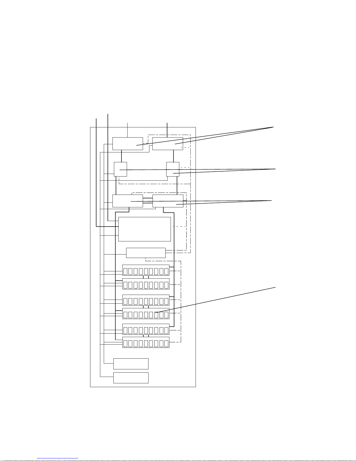
The Sun StorEdge 3910 system targets the midrange DAS market. This product
offers a model that uses two Sun StorEdge Network FC Switch-8 switches as the host
interface. The Sun StorEdge 3910 system can support up to four Sun StorEdge T3+
array partner groups.
system.
FIGURE 1-1 provides an illustration of the Sun StorEdge 3910
Service
port
Modem
out
Fibre Channel Ports
Sun StorEdge Network
FC Switch-8
Storage Service
Processor
Ethernet hub
Sun StorEdge T3+ arrays
(partner groups)
FIGURE 1-1 Sun StorEdge 3910 System
Power Grid 1
Power Grid 2
Chapter 1 Introduction 3
Page 22
Service
port
Modem
out
Storage Service
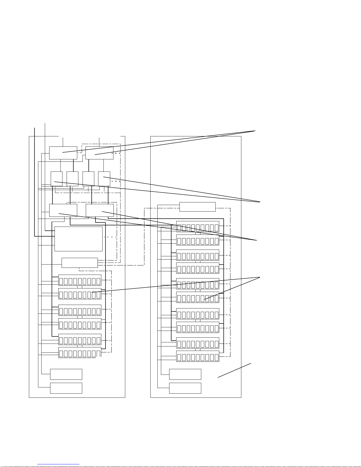
Sun StorEdge 3960 System
The Sun StorEdge 3960 system targets the enterprise DAS market. The product uses
two Sun StorEdge Network FC Switch-16 switches as the host interface and can
support up to four Sun StorEdge T3+ array partner groups in one cabinet. By adding
a Sun StorEdge 3960 Expansion Cabinet, the Sun StorEdge 3960 system supports up
to nine Sun StorEdge T3+ array partner groups.
3960 system.
Fibre Channel Ports
Ethernet hub
Processor
Ethernet hub
FIGURE 1-2 shows the Sun StorEdge
Sun StorEdge
Network FC
Switch-16
Power Grid 1 Power Grid 1
Power Grid 2 Power Grid 2
FIGURE 1-2 Sun StorEdge 3960 System
4 Sun StorEdge 3900 and 6900 Series Reference Manual • February 2002
Sun StorEdge
T3+ arrays
(partner groups)
Sun StorEdge 3960
Expansion Cabinet
Page 23
Sun StorEdge 6910 System
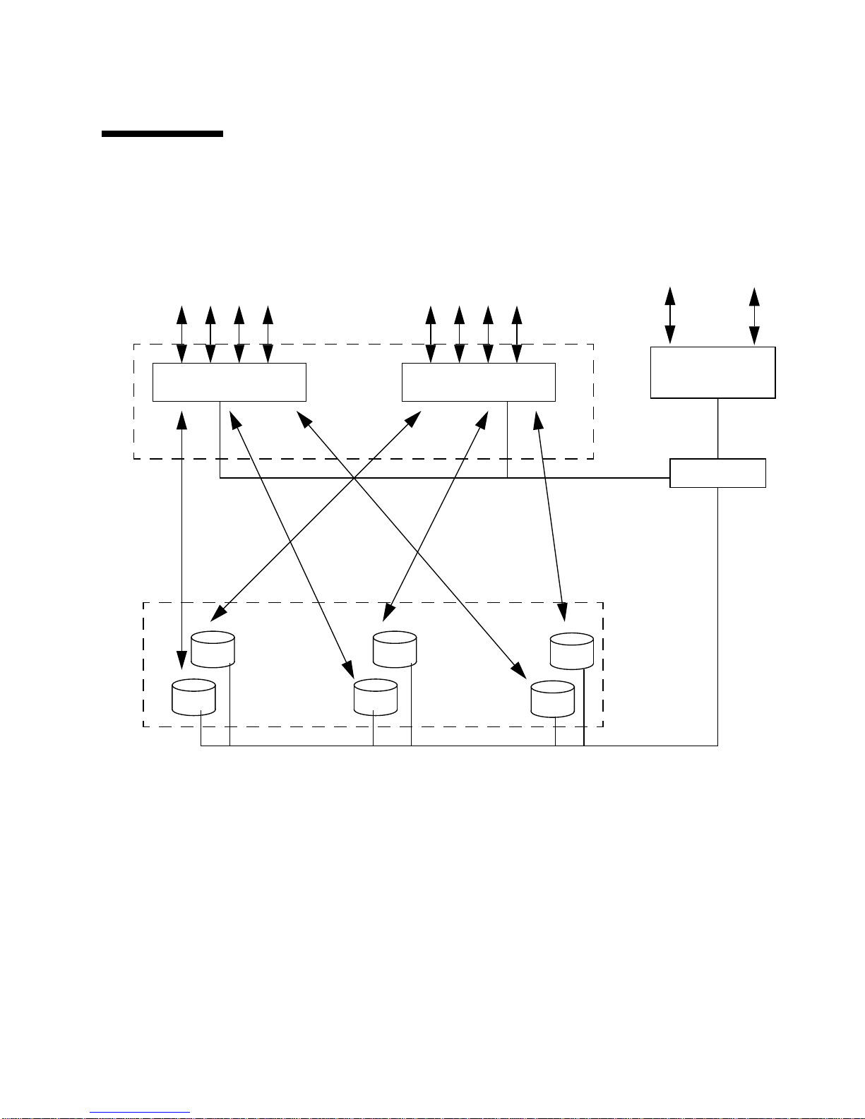
The Sun StorEdge 6910 system targets the midrange SAN market. The system uses
two Sun StorEdge Network FC Switch-8 switches as the host interface and can
support up to three Sun StorEdge T3+ partner groups.
StorEdge 6910 system.
Service
port
Modem
out
Fibre Channel Ports
Storage Service
Processor
FIGURE 1-3 shows the Sun
Sun StorEdge
Network FC
Switch-8 switches
Virtualization
engines
Sun StorEdge
Network FC
Switch-8 switches
Ethernet hub
Power Grid 1
Power Grid 2
FIGURE 1-3 Sun StorEdge 6910 System
Sun StorEdge
T3+ arrays
(partner groups)
Chapter 1 Introduction 5
Page 24
Service
port
Sun StorEdge 6960 System
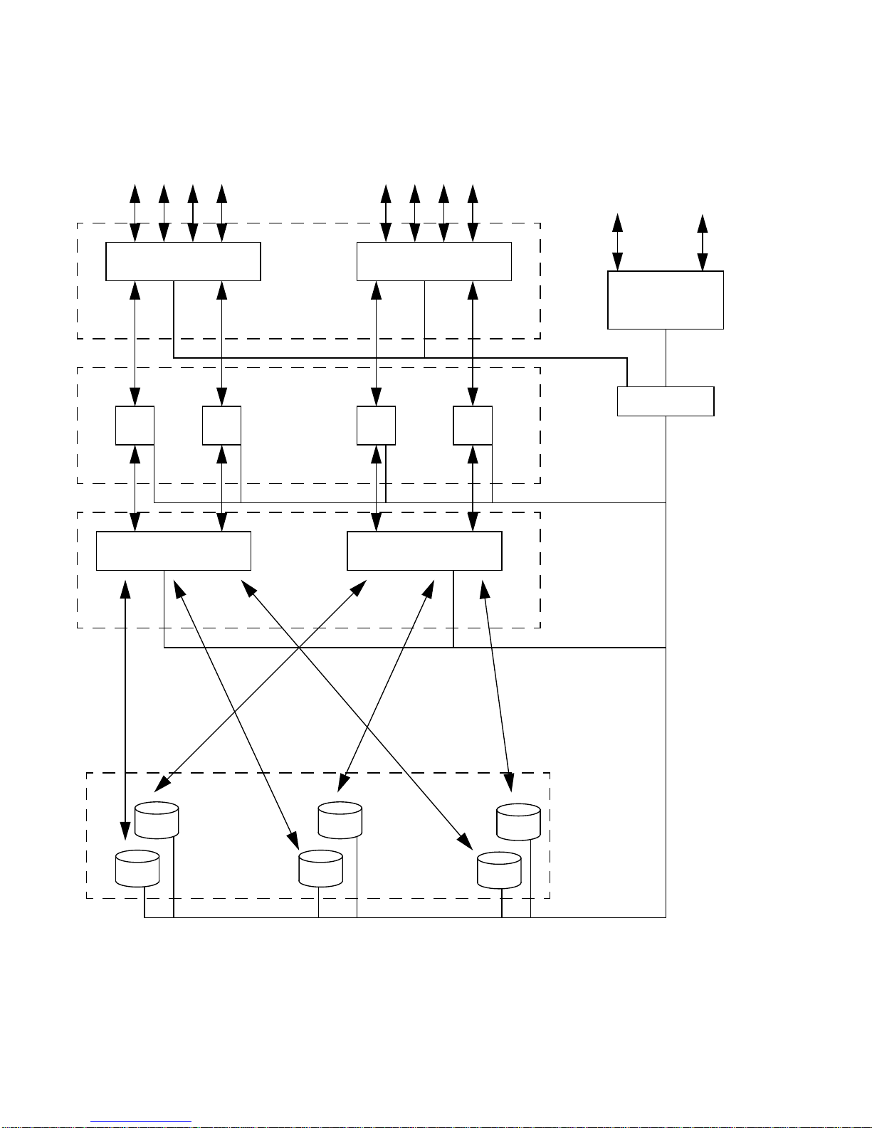
The Sun StorEdge 6960 system targets the enterprise SAN environment. The system
uses two Sun StorEdge Network FC Switch-16 switches as the host interface and can
support up to three Sun StorEdge T3+ array partner groups in one cabinet. By
adding a Sun StorEdge 6960 expansion cabinet, the system supports up to eight Sun
StorEdge T3+ array partner groups.
Modem
out
Fibre Channel Ports
FIGURE 1-4 shows the Sun StorEdge 6960 system.
Sun StorEdge
Network FC
Switch-16
Virtualization
engines
Ethernet hub
Storage Service
Processor
Ethernet hub
Power Grid 1 Power Grid 1
Power Grid 2
Power Grid 2
Sun StorEdge
Network FC
Switch-16
Sun StorEdge
T3+ arrays
(partner groups)
Sun StorEdge 6960
Expansion Cabinet
FIGURE 1-4 Sun StorEdge 6960 System
6 Sun StorEdge 3900 and 6900 Series Reference Manual • February 2002
Page 25
Architecture
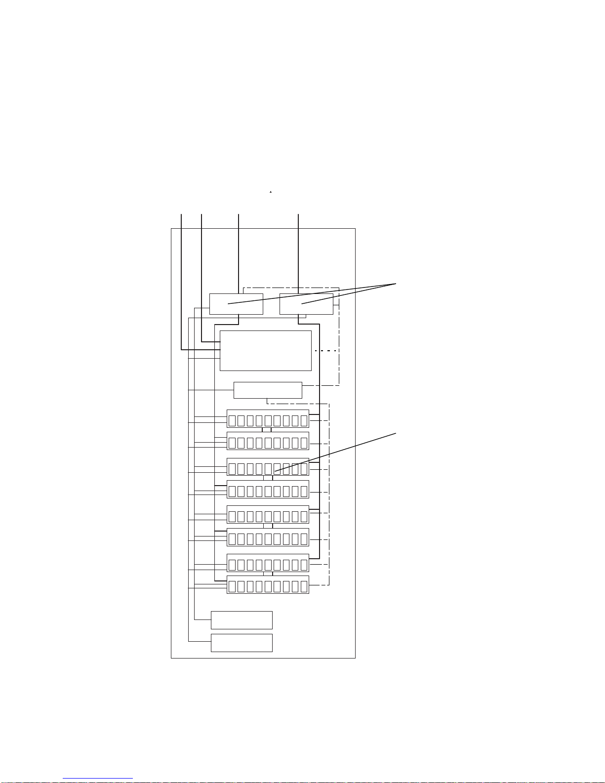
The basic architecture of the Sun StorEdge 3900 series DAS configuration is shown in
FIGURE 1-5.
ModemExt LAN
Fibre Channel switch
Sun StorEdge
T3+ arrays
Host interface
Fibre Channel switch
Storage Service
Processor
Ethernet hub
Internal
component
LAN
FIGURE 1-5 Basic Sun StorEdge 3900 Series Architecture
Chapter 1 Introduction 7
Page 26
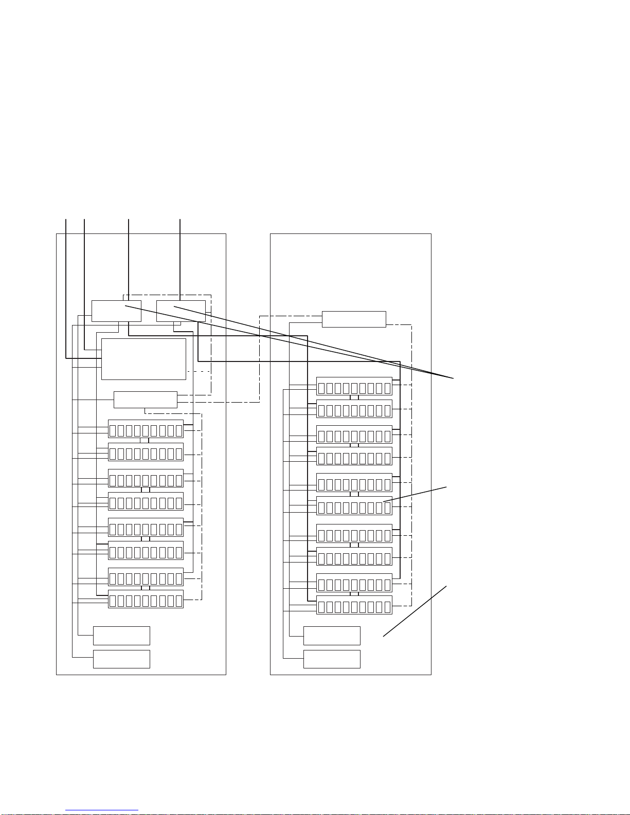
The basic architecture of the Sun StorEdge 6900 series SAN configuration is shown
in
FIGURE 1-6.
Fibre Channel switch Fibre Channel switch
ModemExt LAN
VE
VE VE VE
Fibre Channel switch
Host interface
Virtualization
engine layer
Storage Service
Processor
Ethernet hub
Fibre Channel switch
Sun StorEdge
T3+ Arrays
FIGURE 1-6 Basic Sun StorEdge 6900 Series Architecture
8 Sun StorEdge 3900 and 6900 Series Reference Manual • February 2002
Internal
component
LAN
Page 27

System-Level Support Information
The supported Sun StorEdge 3900 and 6900 series subsystems are shown in
TABLE 1-1.
TABLE 1-1 Sun StorEdge 3900 and 6900 Series System-Level Configurations
Systems Bandwidth Capacity Maximum LUNs
LUN
Masking Host Connectivity
Sun StorEdge 3910
system (DAS)
Sun StorEdge 3960
system (DAS)
Sun StorEdge 6910
system (SAN)
Sun StorEdge 6960
system (SAN)
800 Mbytes/sec
maximum
1400 Mbytes/
sec maximum
200 Mbytes/sec
maximum
400 Mbytes/sec
maximum
648 Gbytes to
5.2 Tbytes
648 Gbytes to
11.7 Tbytes
648 Gbytes to
3.9 Tbytes
648 Gbytes to
10.4 Tbytes
16 (2 per Sun
StorEdge T3+
array)
36 (2 per Sun
StorEdge T3+
array)
512 Yes 1-to-7Redundant
1024 Yes 1-to-14
No 1-to-4Redundant
Pairs
No 1-to-7Redundant
Pairs
Pairs
Redundant Pairs
Features
The features of the Sun StorEdge 3900 and 6900 series storage subsystems are given
in the following subsections:
■ “Sun StorEdge 3900 and 6900 Series Common Features” on page 9
■ “Sun StorEdge 3900 Series Features” on page 11
■ “Sun StorEdge 6900 Series Features” on page 11
Sun StorEdge 3900 and 6900 Series Common
Features
The following are features available on both the Sun StorEdge 3900 and 6900 series:
■ Installation—The Sun StorEdge 3900 and 6900 series are delivered as minimum-
setup-required storage subsystems. The Sun StorEdge T3+ array partner group
logical units (LUNs) are preconfigured at the factory.
Chapter 1 Introduction 9
Page 28

■ RAID Striped Data with Standby Hot Spare—Internal Sun StorEdge T3+ array
LUNs are preconfigured as RAID 5 (8 drives, plus a standby hot spare).
Configuration tools are provided on the Service Processor that enable internal
configuration of the Sun StorEdge T3+ arrays to be changed to a limited set of
configurations. Preconfigured LUNs comprising 36-Gbyte disk drives are 236
Gbytes each, while preconfigured LUNs comprising 73-Gbyte disk drives provide
477 Gbytes each.
■ Bandwidth—All of the storage subsystems use Fibre Channel technology to
provide the best available bandwidth. Current FC technology offers 1.06 Gbit/
second transfers (~ 80 Mbytes/second average). The actual bandwidth delivered
might be less, depending on the configuration.
■ Capacity—The storage subsystems that have 36-Gbyte disk drives offer a
minimum of 648 Gbytes and a maximum of 1.9 to 5.8 Tbytes of disk space,
depending on the model selected. The subsystem has a footprint no larger than
12.29 square feet.
The storage subsystems that have 73-Gbyte disk drives offer a minimum of 1.3
Tbytes and a maximum of 3.9 to 11.7 Tbytes of disk space, depending on the
model selected. The subsystem has a footprint no larger than 12.29 square feet.
■ Data Path Redundancy—All of the storage subsystems provide full data path
redundancy with no data path component as a single point of failure, offering
24x7 data availability. Redundant components include the Fibre Channel
switches, Sun StorEdge T3+ array storage bricks, virtualization engines (on Sun
StorEdge 6900 series only), and dual Power Distribution Units (PDUs).
■ Host Managed Multipathing—All of the storage subsystems present two
physical I/O paths to devices on each host. Host software is required to manage
the I/O utilization of the presented I/O paths. Such software includes, but is not
limited to, either Sun StorEdge Traffic Manager (MPxIO) software or VERITAS
Dynamic Multi-Pathing (VxDMP).
■ Host Support—The Sun StorEdge 3900 and 6900 series support the following:
■ Solaris 8 07/01 and later releases (all Sun StorEdge 3900 and 6900 series
systems)
■ Sun Cluster 3.n (all Sun StorEdge 3900 and 6900 series systems)
■ Windows NT Enterprise Edition 4.0, Service Pack 6
■ Windows 2000 Server and Windows 2000 Advanced Server, Service Pack 2
■ Local or Remote Serviceability —All solution subsystems include a Service
Processor. Support for the Remote Support System (RSS) is built into the Service
Processor. All Sun StorEdge 3900 and 6900 series subsystems support Sun
StorEdge Remote Response software. Support for onsite enterprise service
through Ethernet connection into the Service Processor is included.
■ Hot Swappable FRUs—All solution subsystems use hot-swappable field-
replaceable units (FRUs), where available. The FRUs include power supplies,
cooling units, disk drives, and RAID controllers. The Service Processor is a FRU.
10 Sun StorEdge 3900 and 6900 Series Reference Manual • February 2002
Page 29

Sun StorEdge 3900 Series Features
The following are features available on the Sun StorEdge 3900 series:
■ Multiple HBA Support—The Sun StorEdge 3900 series DAS solution subsystems
can be configured to provide from 1 to 7 HBA connections per switch (a
minimum of two connections per host) concurrently. The Sun StorEdge 3910
system can support from 1 to 4 HBAs per switch, while the Sun StorEdge 3960
can support from 1 to 7 HBAs per switch.
■ Host Connect Support—The Sun StorEdge 3900 series support the host
connection as a Fibre Channel switch F Port. The LUNs presented are accessible
as Fabric devices. SAN solution subsystem models support the host connection as
a Fibre Channel switch F Port. Virtual LUNs (VLUNs) presented are accessible as
Fabric devices, as defined by the Sun StorEdge Network FC Switch-8 or Switch-16
switch rules. Support for an NT server requires the SL port on the Fibre Channel
switch.
Sun StorEdge 6900 Series Features
The following are features available on the Sun StorEdge 6900 series:
■ LUN Carving and Masking - The ability to carve the underlying Sun StorEdge
T3+ array LUNs into small VLUNs for increased device support and customized
storage usage is provided in the Sun StorEdge 6900 series subsystems.
■ Host Connect Support - The Sun StorEdge 6900 series SAN solutions support the
host connect as a Fibre Channel F port. VLUNs presented are accessible as Fibre
Channel devices, as defined by the Sun StorEdge Network FC Switch-8 and
Switch-16 switch rules.
■ Multiple HBA Support—The Sun StorEdge 6900 series SAN solution subsystems
can be configured to provide from 1 to 14 connections to the host for HBAs. The
Sun StorEdge 6910 can have from 1 to 7 redundant HBA connections (a minimum
of two connections per host) concurrently. The Sun StorEdge 6910 system can
support from 1 to 4 HBAs per switch, while the Sun StorEdge 6960 can support
from 1 to 7 HBAs per switch.
Chapter 1 Introduction 11
Page 30

12 Sun StorEdge 3900 and 6900 Series Reference Manual • February 2002
Page 31

CHAPTER
2
Component Descriptions
This chapter offers an overview of the components of the Sun StorEdge 3900 and
6900 series storage subsystems. This overview includes a listing of the hardware and
software used by the storage subsystems.
This chapter is organized as follows:
■ “Hardware Component Descriptions” on page 13
■ “Software Component Descriptions” on page 17
Hardware Component Descriptions
The hardware building blocks for the Sun StorEdge 3900 and 6900 series include:
■ Storage Service Processor
■ Virtualization engine (Sun StorEdge 6900 series only)
■ Customer management connection
■ Storage devices
■ Ethernet hub
■ Fibre Channel switches
■ Sun StorEdge expansion cabinet
Storage Service Processor
The Storage Service Processor is a Netra™ X1 server. The Netra is delivered as part
of the Sun StorEdge 3900 and 6900 series and provides a 500-MHz, 64-bit
UltraSPARC™ processor, 512 Mbytes of memory, and a 40-Gbyte IDE internal drive.
13
Page 32

The Storage Service Processor is responsible for the following:
■ Monitoring the components in the Sun StorEdge 3900 and 6900 series.
■ Fault isolation, verification, and notification of a FRU that is failing.
■ Some limited non-mission critical-configuration functions including configuration
of the Sun StorEdge T3+ arrays, virtualization engine, and Fibre Channel
switches.
■ Serves as the service portal to all components in the Sun StorEdge 3900 or 6900
series subsystems.
Every Storage Service Processor is configured with the same hardware and software
components to ensure ease of replacement. All Storage Service Processors can
support the Sun StorEdge Remote Response option if the necessary hardware and
software are added.
Any single Storage Service Processor can become the collection point for other
geographically local Storage Service Processors, which is referred to as the master
Storage Service Processor.
Virtualization Engines
The virtualization engines are a pair of routers used when building a SAN
environment for the Sun StorEdge 6900 series subsystem. There is one pair of
virtualization engines in the Sun StorEdge 6910 system and there are two pairs of
virtualization engines in the Sun StorEdge 6960 system.
The virtualization engine provides the following functions:
■ LUN carving, or creating smaller virtual drives from physical LUNs
■ LUN masking, which restricts host HBA access to the virtual LUNs
The virtualization engine supports the multipathing functionality of the Sun
StorEdge T3+ array. That is, each unit in the Sun StorEdge 6910 system provides
physical access to all of the underlying Sun StorEdge T3+ arrays. Each virtualization
engine in the Sun StorEdge 6960 system provides physical access to half of the
underlying Sun StorEdge T3+ array partner groups. The virtualization engine pairs
offer two I/O paths to individual StorEdge T3+ arrays.
Virtual and physical device map synchronization is used by the virtualization
engine. If a virtualization engine fails, the second virtualization engine of the pair
maintains the I/O availability. All virtualization engine pairs use a single device
mapping of physical-to-virtual devices. A change in the physical or virtual mapping
results in a re-synchronization of the device mappings throughout the virtualization
engine pairs. To accomplish the synchronization, each virtualization engine pair is
connected to the other virtualization engine through a redundant pair of Fibre
Channel switch T-ports.
14 Sun StorEdge 3900 and 6900 Series Reference Manual • February 2002
Page 33

Customer-Management Connection
The customer-management connection is a dedicated Ethernet connection provided
on each Storage Service Processor that connects to the designated master Sun
StorEdge 3900 and 6900 series storage subsystem. The master Storage Service
Processor is used to collect status data from each Sun StorEdge 3900 and 6900 series
machine using the LAN. The master Storage Service Processor then reports the
status data used by the Storage Service Processor that is equipped with Sun
StorEdge Remote Response software.
Customers can alternatively choose to do one or more of the following:
■ Use their management LAN to support network traffic other than that reported
by the Sun StorEdge Remote Response software.
■ Provide a private LAN to isolate the service traffic from customer traffic.
■ Supply a secure router to isolate the customer LAN from the Service Processor
LAN.
Storage Devices
The Sun StorEdge T3+ array, both the 36-Gbyte and 73-Gbyte versions, provides
backend data storage. In factory-configured basic configurations, the Sun StorEdge
T3+ arrays are configured with two LUNs per partner group or one LUN per
physical unit. Each LUN is a full-capacity RAID 5 (8 disks) volume with a segment
size of 16 Kbytes and is configured with a standby hot spare. Additional utilities are
provided on the Storage Service Processor that enable Sun-trained personnel to
reconfigure the Sun StorEdge T3+ array LUNs to meet workload performance
requirements.
The RAID levels supported by the Sun StorEdge T3+ array in the Sun StorEdge 3900
and 6900 series configurations are:
■ RAID 1 - Each data block in a RAID 1 volume is mirrored on two physical drives.
If one of the mirrored pair fails, the data from the other drive is used. Because the
data is mirrored in a RAID 1 configuration, the volume has only half the capacity
of the assigned drives. For example, if you create a 4-drive RAID 1 volume with
36-Gbyte drives, the resulting data capacity is4x36/2=72Gbytes.
■ RAID 5 - In a RAID 5 configuration, data is striped across the drives in the
volumes in segments, with parity information being striped across the drives, as
well. Because of this parity, if a single drive fails, data can be recovered from the
remaining drives. Two drive failures cause all data to be lost. A RAID 5 volume
has the data capacity of all the drives in the logical unit, less one. For example, a
5-drive RAID 5 volume with 73-Gbyte drives has a capacity of (5—1) x 73 = 292
Gbytes.
Chapter 2 Component Descriptions 15
Page 34

Ethernet Hub
The Sun StorEdge 3900 and 6900 series uses an Ethernet hub as the backbone for the
internal service network. The allocation of Ethernet ports is as follows:
■ 1 - Service Processor (per subsystem)
■ 1 - For each Fibre Channel switch
■ 1 - For each virtualization engine
■ 2 - For each Sun StorEdge T3+ array partner group
■ 1 - For the Ethernet hub that is installed in the second Sun StorEdge Expansion
Cabinet in the Sun StorEdge 3960 and 6960 systems
Fibre Channel Switches
The Sun StorEdge Network FC Switch-8 or Switch-16 switch provides cable
consolidation and increased connectivity. The Sun StorEdge Network FC Switch-8
and Switch-16 switches are used for the internal data interconnection infrastructure.
The switches are paired to provide redundancy. Two switches are used in each Sun
StorEdge 3900 series storage subsystem and four switches are used in each Sun
StorEdge 6900 series storage subsystem. Each switch is connected, through Ethernet,
to the service network for management and service from the Service Processor.
These switches can be monitored through the SANSurfer GUI, which is available on
the Storage Service Processor.
These switches are configured using the configuration utilities, which are discussed
in “Configuration Utilities” on page 18.
Sun StorEdge Expansion Cabinet
The Sun StorEdge 3900 and 6900 series are packaged in the Sun StorEdge Expansion
Cabinet, which is used for several other Sun products. This provides a consistent
look and feel. The customer accessible areas of a storage subsystem are clearly
labeled. Service-accessible areas of the storage subsystem will be clearly labeled as
such. All physical configurations will be completed by Sun-trained personnel. NonSun-service trained customers will have significantly limited access to the physical
layout of the storage subsystem.
16 Sun StorEdge 3900 and 6900 Series Reference Manual • February 2002
Page 35

Software Component Descriptions
The software included in the Sun StorEdge 3900 and 6900 series storage subsystems
are:
■ Solaris 8 operating environment
■ Sun StorEdge Remote Response (to support optional service)
■ Configuration utilities
■ Storage Automated Diagnostic Environment
■ SANSurfer
■ Explorer data collection utility
Note – The software packaged with the Sun StorEdge 3900 and 6900 series storage
subsystem is not meant for use on the host servers.
Solaris 8
The Solaris 8 10/01 operating environment is installed on the Storage Service
Processor.
Sun StorEdge Remote Response
Optionally, you can add the Sun StorEdge Remote Response capability to your Sun
StorEdge 3900 and 6900 series. Sun StorEdge Remote Response provides “phone
home” capability and dial-back diagnostics. This enables Sun storage experts to
remotely troubleshoot, diagnose, and service Sun StorEdge T3+ arrays and switches.
The features of Sun StorEdge Remote Response include:
■ Fast response and reaction to alerts and alarms
■ Remote troubleshooting, diagnosis, and repair
■ Increased system availability
■ Reduced cost of ownership
Chapter 2 Component Descriptions 17
Page 36
Configuration Utilities
The configuration utilities are a collection of commands that enable Sun service
personnel to perform maintenance on the components of the Sun StorEdge 3900 and
6900 series subsystems.
The configuration utilities can be accessed using:
■ Menu-driven character user interface
■ Command line
■ Sun StorEdge Resource Suite configuration service graphical user interface
These utilities enable you to:
■ Configure, check, and display information about the attached Sun StorEdge T3+
partner groups
■ Configure, check, and display information about the attached Sun switches
■ Configure, check, and display information about the attached virtualization
engines
■ Determine storage subsystem type and model number
■ View detailed configuration utility messages in the log file
Storage Automated Diagnostic Environment
The Storage Automated Diagnostic Environment is a combination of Network
Storage Agent 2.x, Stortools™ 4.x, and the configuration graphical user interface into
a single utility.
For detailed information, refer to the Storage Automated Diagnostic Environment User ’s
Guide, part number 816-3142-10.
Diagnostics
The diagnostic package extends SunVTS™ for Sun StorEdge Fibre Channel products
and aids Sun service personnel and Sun authorized service providers in
troubleshooting the Sun StorEdge network FC switches, Sun StorEdge T3+ arrays,
and other Sun StorEdge hardware on Solaris 8 platforms.
Caution – Do not run the configuration utilities at the same time as diagnostics.
18 Sun StorEdge 3900 and 6900 Series Reference Manual • February 2002
Page 37

Note – Because the Storage Service Processor has no access to the data path, the
only diagnostic tests that function are the ones for the Sun StorEdge Network FC
Switch-8 and Switch-16 switches.
Storage Automated Diagnostic Environment Agent
The Storage Automated Diagnostic Environment Agent is a server-based online
health and diagnostic monitoring tool for storage area network (SAN) devices and
direct-attached storage devices. It can be configured to monitor on a 24-hour basis,
collecting information that enhances the reliability, availability, and serviceability
(RAS) of the storage devices.
The Storage Automated Diagnostic Environment Agent remotely monitors Sun
network storage devices. The Storage Automated Diagnostic Environment Agent can
monitor host message files for errors in order to obtain status information about each
device being monitored when run on the customer’s host.
The primary features of the Storage Automated Diagnostic Environment Agent are:
■ Health monitoring and fault detection - Reports on conditions that can impact the
availability and operation of the storage devices.
■ Alert notification - Automatically sends event notifications to system
administrators and other designated parties if the path exists.
■ Telemetry stream - Sends out events and information to Sun that facilitate
improved service and improved products (if configured).
■ Lightweight - The Storage Automated Diagnostic Environment Agent requires
minimal resources in terms of disk space, compute cycles, and virtual memory
footprint.
■ Modular architecture - Easy plug-in support for additional devices and functions.
Configuration User Interface
The configuration user interface provides a web-based graphical user interface that
enables administrators to perform configuration of the Sun StorEdge 3900 and 6900
series.
All the functionality that is available from the “Configuration Utilities” on page 18 is
available from the Sun StorEdge Resource Suite configuration service.
Chapter 2 Component Descriptions 19
Page 38
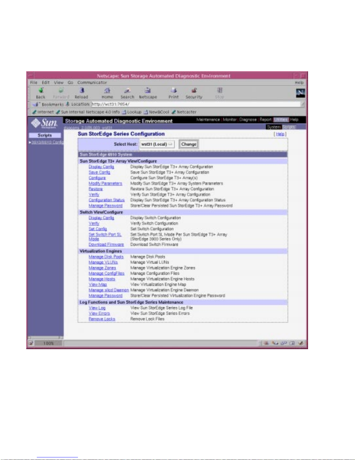
From the web browser you can configure the virtualization engine, Sun StorEdge
T3+ storage arrays, and Sun StorEdge network FC switches.
FIGURE 2-1 Configuration Utilities User Interface
For detailed instructions on starting and using the Storage Automated Diagnostic
Environment, refer to the Storage Automated Diagnostic Environment User’s Guide.
20 Sun StorEdge 3900 and 6900 Series Reference Manual • February 2002
Page 39

SANSurfer
SANSurfer is a graphical user interface (GUI) that enables you to monitor switch
products connected to Sun servers. Each GUI window monitors a different aspect of
the Sun StorEdge Network FC Switch-8 or Switch-16 or Fibre Channel configuration.
SANSurfer enables you to perform the following procedures.
■ Display multiple fabrics.
■ Associate the switch management interface with its IP network configuration
parameters.
■ View the Fibre Channel connection.
■ View hardware and firmware version information for the selected chassis.
■ View Switch Names and World Wide Names (WWNs).
■ View port addresses on the selected chassis.
The SANSurfer Help menu contains information about the product and a complete
online help guide.
Explorer Data Collection Utility
The explorer data collection utility compiles information about the operating system
that is installed on the Storage Service Processor along with information about the
Sun StorEdge network FC switches and the Sun StorEdge T3+ arrays. The
information is used for troubleshooting purposes. All information is stored in a
tar(1) file that can be sent to Sun service for evaluation.
Chapter 2 Component Descriptions 21
Page 40

22 Sun StorEdge 3900 and 6900 Series Reference Manual • February 2002
Page 41

CHAPTER
3
Default Configurations and Settings
This chapter presents information about the default Sun StorEdge 3900 and 6900
series configurations. The information includes all settings for the virtualization
engine, Sun StorEdge T3 + arrays, Ethernet addresses, and Sun StorEdge Network
FC switches.
This chapter is organized as follows:
■ “Sun StorEdge 3900 and 6900 Series Layout” on page 24
■ “Virtualization Engine Settings” on page 26
■ “Sun StorEdge T3+ Array Settings” on page 29
■ “Sun StorEdge Network FC Switch Settings” on page 32
■ “Ethernet Address Settings” on page 37
23
Page 42
Sun StorEdge 3900 and 6900 Series
Layout
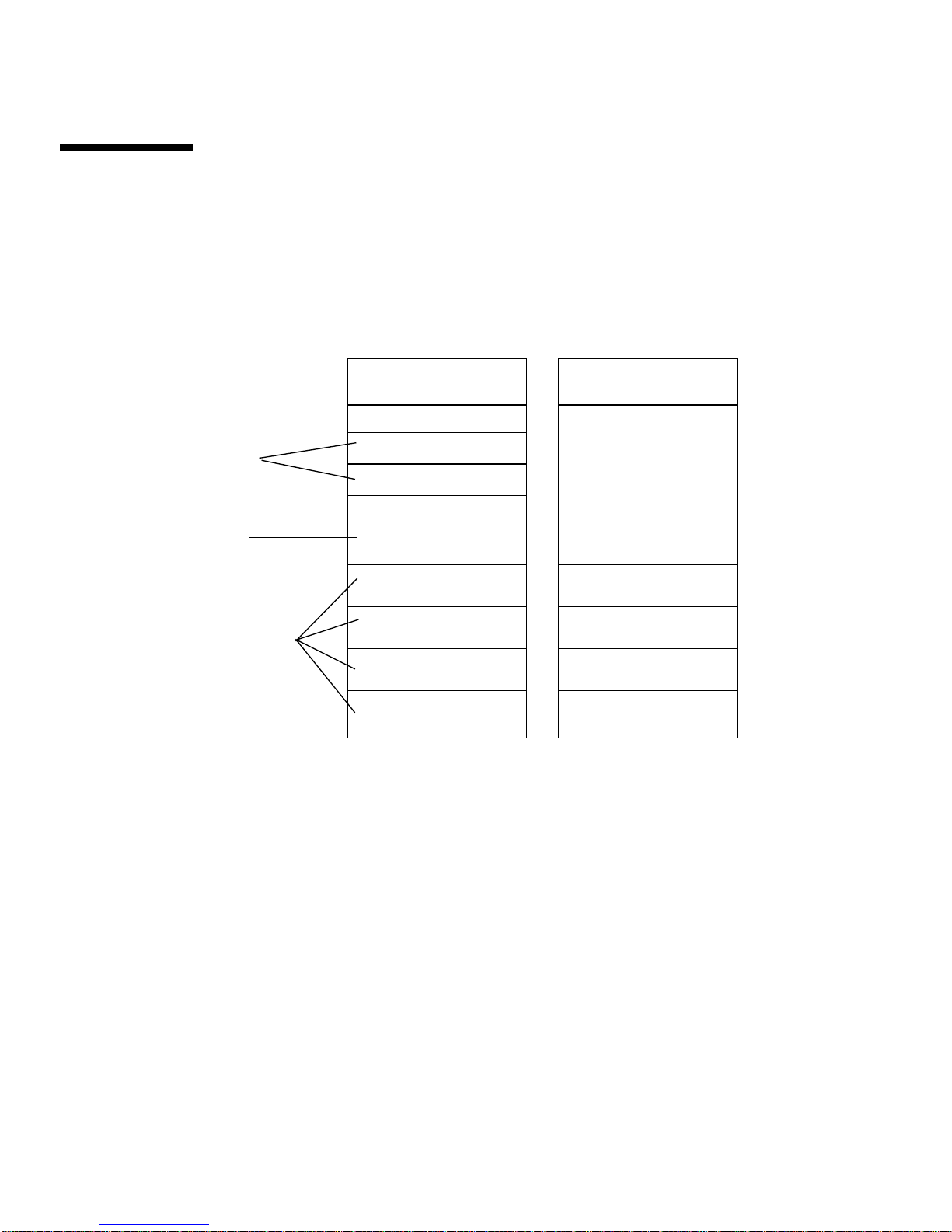
FIGURE 3-1 shows the layout (rear view) of the hardware components in the Sun
StorEdge 3960 system. The Sun StorEdge 3910 has the same layout, without the
expansion cabinet.
Ethernet hub
blank
sw1a
Switches
sw1b
Storage
Service
Processor
Sun StorEdge
T3+ Arrays
FIGURE 3-1 Rear View of the Sun StorEdge 3960 System
blank
(sp0)
t3b3
t3b2
t3b1
t3b0
Ethernet hub
blank
t3be4
t3be3
t3be2
t3be1
t3be0
24 Sun StorEdge 3900 and 6900 Series Reference Guide • February 2002
Page 43
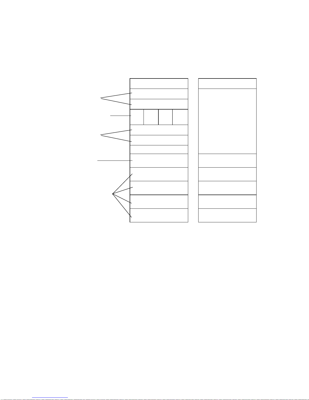
FIGURE 3-2 shows the layout (rear view) of the hardware components in the Sun
StorEdge 6960 system. The Sun StorEdge 6910 has the same layout, without the
expansion cabinet and without the additional virtualization engine pair (that is v2a
and v2b).
Switches
Virtualization
Engines
Switches
Storage
Service
Processor
Sun StorEdge
T3+ Arrays
Ethernet hub
sw1a
sw1b
v1a v2a v1b v2b
sw2a
sw2b
blank
(sp0)
t3b3
t3b2
t3b1
t3b0
Ethernet hub
blank
t3be4
t3be3
t3be2
t3be1
t3be0
FIGURE 3-2 Rear View of the Sun StorEdge 6960 System
Chapter 3 Default Configurations and Settings 25
Page 44
Virtualization Engine Settings
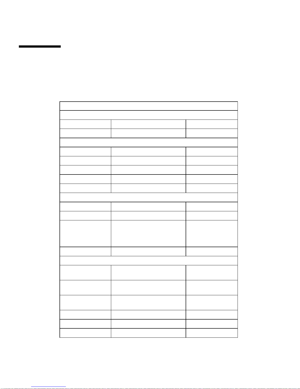
The standard settings for the virtualization engine are given in TABLE 3-1.
TABLE 3-1 Standard Virtualization Engine Settings
Standard Virtualization Engine Settings
Device Side Settings
Operating mode: Pt-to-pt mode
UID reporting scheme: Port
Host Side Settings
Operating mode: Pt-to-pt mode
LUN mapping mode: Direct LUN mapping
Command queue depth: 0
HS/DS UID distinguish: Enable
UID reporting scheme: Port
Ethernet
Subnet mask: 255.255.255.0
Default gateway: 192.168.0.1
IP address: v1a - 192.168.0.20
Server port number (5000-65535): 25000
SV Management Programs
Router management program
access is: Enabled
Host WWN authentications are: 1. Unassigned
Host IP authentications are: 1. 255.255.255.255
Other router’s IP is: n.n.n.n
Password Protection is Disabled
Password is Invalid
v1b - 192.168.0.21
v2a - 192.168.0.22
v2b - 192.168.0.23
2. Unassigned
2. 255.255.255.255
1
2
2
26 Sun StorEdge 3900 and 6900 Series Reference Guide • February 2002
Page 45
1 - The other router’s IP address is based on Virtualization Engine pairs. v1a and v1b are a pair and so are v2a and v2b. The value that
must be entered is the IP address of the other router in the pair. For instance, if you are setting up the v1a you enter the IP address of
v1b.
2- The password selections do not set the password for telnet(1) or ftp(1). These passwords are set by the Ethernet setting.
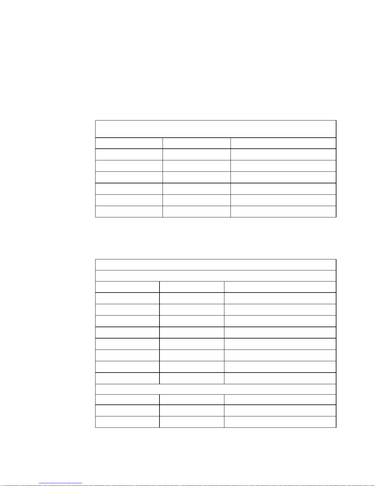
The Sun StorEdge 6910 system default settings are shown in TABLE 3-2.
TABLE 3-2 Sun StorEdge 6910 System Defaults
Sun StorEdge 6910 Default System - One Virtualization Engine Map
(v1a, v1b Vir tualization Engine Pair)
Disk Pool Number of VLUNs VLUN Size (73-Gbytes/36-Gbytes drives)
t3b00 1 477-Gbytes/236-Gbytes
t3b01 1 477-Gbytes/236-Gbytes
t3b10 1 477-Gbytes/236-Gbytes
t3b11 1 477-Gbytes/236-Gbytes
t3b20 1 477-Gbytes/236-Gbytes
t3b21 1 477-Gbytes/236-Gbytes
The Sun StorEdge 6960 system default settings are given in
TABLE 3-3 Sun StorEdge 6960 System Defaults
Sun StorEdge 6960 System - Two Vir tualization Engine Maps
(v1a, v1b Vir tualization Engine Pair)
Disk Pool Number of VLUNs VLUN Size (73-Gbytes/36-Gbytes drives)
TABLE 3-3.
t3b00 1 477-Gbytes/236-Gbytes
t3b01 1 477-Gbytes/236-Gbytes
t3b20 1 477-Gbytes/236-Gbytes
t3b21 1 477-Gbytes/236-Gbytes
t3be10 1 477-Gbytes/236-Gbytes
t3be11 1 477-Gbytes/236-Gbytes
t3be30 1 477-Gbytes/236-Gbytes
t3be31 1 477-Gbytes/236-Gbytes
(v2a, v2b Vir tualization Engine Pair)
Disk Pool Number of VLUNs VLUN Size (73-Gbytes/36-Gbytes drives)
t3b10 1 477-Gbytes/236-Gbytes
t3b11 1 477-Gbytes/236-Gbytes
Chapter 3 Default Configurations and Settings 27
Page 46
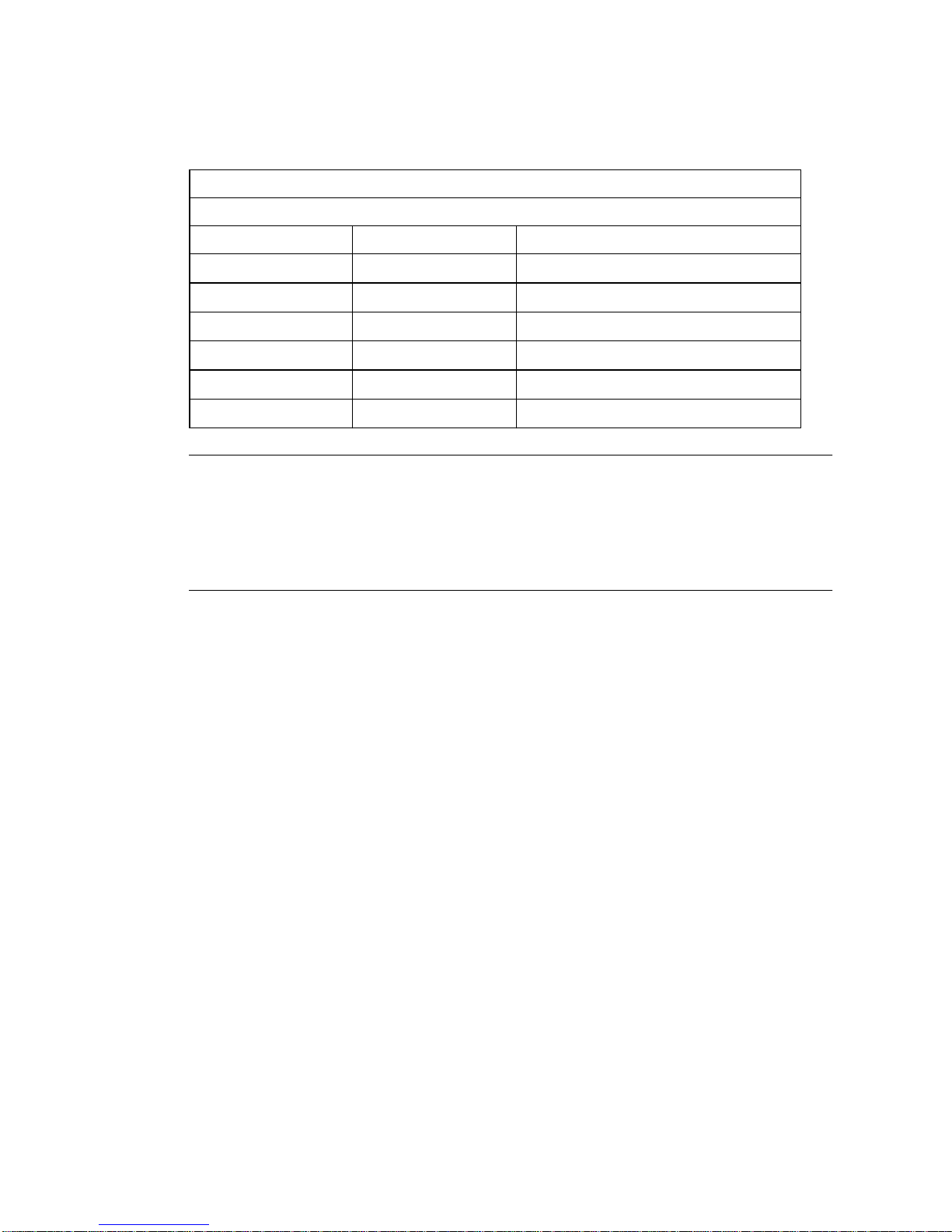
TABLE 3-3 Sun StorEdge 6960 System Defaults
Sun StorEdge 6960 System - Two Vir tualization Engine Maps
(v1a, v1b Vir tualization Engine Pair)
Disk Pool Number of VLUNs VLUN Size (73-Gbytes/36-Gbytes drives)
t3be00 1 477-Gbytes/236-Gbytes
t3be01 1 477-Gbytes/236-Gbytes
t3be20 1 477-Gbytes/236-Gbytes
t3be21 1 477-Gbytes/236-Gbytes
t3be40 1 477-Gbytes/236-Gbytes
t3be41 1 477-Gbytes/236-Gbytes
Note – The default disk pool and VLUN assignments are one disk pool per Sun
StorEdge T3+ array LUN, named by using the Sun StorEdge T3+ array host name
with a number (0 or 1) appended. A single VLUN is carved from each disk pool
equivalent to the size of the Sun StorEdge T3+ array LUN. This assumes that a full
complement of Sun StorEdge T3+ arrays is configured as RAID 5. This description
applies to both the Sun StorEdge 6910 system and the Sun StorEdge 6960 system.
28 Sun StorEdge 3900 and 6900 Series Reference Guide • February 2002
Page 47

Sun StorEdge T3+ Array Settings
The supported configurations for the Sun StorEdge T3+ arrays are given in TABLE 3-4.
TABLE 3-4
Element
Sun StorEdge T3+ Array Configuration Types
Default DAS
Configuration
1
Default SAN
Configuration DAS/SAN Option 1 DAS/SAN Option 2
Hot Spare Yes Yes Yes Yes
Block Size 16 Kbytes 16 Kbytes 16 Kbytes, 32 Kbytes,
64 Kbytes
16 Kbytes, 32 Kbytes,
64 Kbytes
Cache auto auto auto auto
Mirror auto auto auto auto
Multiplexing Support
2
(mp_support
)
Read Ahead
3
(rd_ahead
)
Sun StorEdge
Traffic Manager
(mpxio)
off off off or on off or on
Read/write
(rw)
Read/write (rw;
DAS/SAN) or Sun
StorEdge Traffic
Manager (mpxio)
(DAS only)
Read/Write (rw;
DAS/SAN) or Sun
StorEdge Traffic
Manager (mpxio)
(DAS only)
Recon Rate medium medium medium medium
RAID Type 5 5 1 or 5 1 and 5
LUNs/Partner Pair 2 2 2 or 4 4
‡
1—All Sun StorEdge 3900 series storage subsystems ship from Sun in the default DAS configuration
2—Multiplexing support in SAN configurations must be set to rw.
3—Read ahead is typically set to off in random access environments. This delivers better overall cache performance.
‡—In this configuration, one LUN per Sun StorEdge T3+ array, two LUNs per array are used by the RAID 1 devices. One LUN per Sun
StorEdge T3+ array, two LUNs per array are used by the RAID 5 devices.The configuration utility assignsthree physical drives to the
RAID 1 device and assigns the remaining five physical drives to the RAID 5 device. The ninth physical drive is always the hot spare.
Chapter 3 Default Configurations and Settings 29
Page 48

The Sun StorEdge T3+ array target IDs and host names are shown in TABLE 3-5.
TABLE 3-5 Sun StorEdge T3+ Array Target ID and Host Name
Sun StorEdge T3+ Array Target ID Host Name
t3b0 0, 1 t3b0
t3b1 2, 3 t3b1
t3b2 4, 5 t3b2
t3b3 6, 7 t3b3
t3be0 8, 9 t3be0
t3be1 10, 11 t3be1
t3be2 12, 13 t3be2
t3be3 14, 15 t3be3
t3be4 16, 17 t3be4
The Sun StorEdge T3+ command configuration settings are given in
TABLE 3-6 Sun StorEdge T3+ Array Set Command Configuration Settings
Parameter Default Value
TABLE 3-6.
bootmode auto
bootdelay 3
sn nnnnnn
ip see
TABLE 3-16
netmask 255.255.255.0
gateway 192.168.0.1
tftphost 0.0.0.0
tftpfile <NULL>
hostname See
TABLE 3-5
vendor 0310
model 501-5710-02(51)
revision 0200
logto *
30 Sun StorEdge 3900 and 6900 Series Reference Guide • February 2002
Page 49

TABLE 3-6 Sun StorEdge T3+ Array Set Command Configuration Settings
Parameter Default Value
loglevel 3
rarp on
mac n:n:n:n:n:n
The command configuration settings for the Sun StorEdge T3+ array system list are
given in
TABLE 3-7 Sun StorEdge T3+ Array System List Command Configuration Settings
Parameter Default Value
blocksize 16 Kbytes
cache auto
mirror auto
mp_support mpxio for DAS default
rd_ahead off
TABLE 3-7.
rw for SAN default
recon_rate med
sys memsize 128 Mbytes
cache memsize 1024 Mbytes
naca off
The Sun StorEdge T3+ array miscellaneous configuration parameters are shown in
TABLE 3-8.
TABLE 3-8 Sun StorEdge T3+ Array Miscellaneous Configuration Parameters
Parameter Default Value
vol init rate = 16
vol verify rate = 1
port host sun
Chapter 3 Default Configurations and Settings 31
Page 50
Sun StorEdge T3+ Array syslog.conf
Configuration
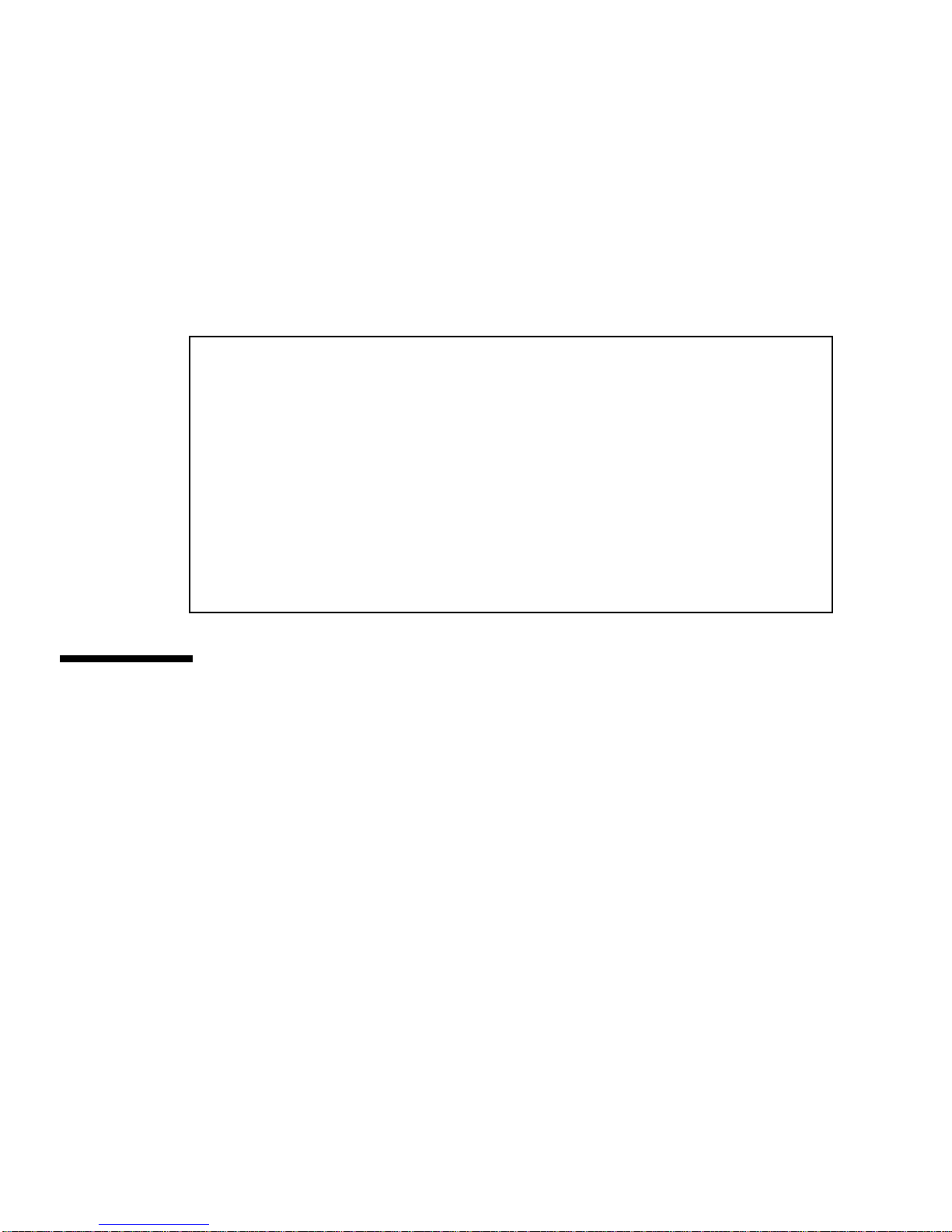
To ensure that the Storage Service Processor is aware of the condition of each Sun
StorEdge T3+ array tray within these storage subsystems, the arrays are configured
to send their syslog.conf information back to the Storage Service Processor.
The information that is placed in each Sun StorEdge T3+ array is as follows:
# syslog.conf
# facility.level action
# messages to local syslog file
*.info /syslog
# messages to syslogd on another host
*.notice @192.168.0.1
# messages sent as SNMP traps
# messages sent as HTTP pushes
*.info | http_push
Sun StorEdge Network FC Switch
Settings
This subsection presents a series of tables that provide information about the default
settings for the Sun StorEdge Network FC Switch-8 and Switch-16 switches. This
information includes the following:
■ Sun StorEdge Network FC Switch-8 and Switch-16 Parameters
■ Sun StorEdge 3910 System Switch Configuration
■ Sun StorEdge 3960 System Switch Configuration
■ Sun StorEdge 6910 System Switch Configuration
■ Sun StorEdge 6960 System Switch Configuration
32 Sun StorEdge 3900 and 6900 Series Reference Guide • February 2002
Page 51

The Sun StorEdge Network FC Switch-8 and Switch-16 parameters are given in
TABLE 3-9.
TABLE 3-9
Field Value
Sun StorEdge Network FC Switch-8 and Switch-16 Parameters
chassis_stage_type IO/T (I/O transfer mode)
port admin mode online (for each port)
HW 1003
CHASSIS TYPE A8 (8-port switch)
A16 (16-port switch)
PROM 30300
FLASH 30462
CHASSIS NUMBER
1
1 (sw1a)
2 (sw1b)
3 (sw2a)
4 (sw2b)
Fabric ID 1
edtov 2560
mfstov 0
ratov 5000
rttov 100
Netmask 255.255.255.0
ARP Timeout 30000
Gateway 192.168.0.1
SNMP Trap Address localhost
SNMP Location Undefined
SNMP Contact Undefined
Chassis Mode 1 online
Port MFS Mode 0 off
1- The default values canbe overriddenwhen youare in a SAN environmentwith multipleSun StorEdge 6900
series systems.
Chapter 3 Default Configurations and Settings 33
Page 52

The default Sun StorEdge 3910 system switch configuration is given in TABLE 3-10.
TABLE 3-10 Sun StorEdge 3910 System Switch Configuration
sw1a sw1b
Four Hard Zones Four Hard Zones
Zone 1 Zone 1
Port 1 = TL (t3b0) Port 1 = TL (t3b0 altmaster)
Port 2 = F (host #1a) Port 2 = F (host #1b)
Zone 2 Zone 2
Port 3 = TL (t3b1) Port 3 = TL (t3b1 altmaster)
Port 4 = F (host #2a) Port 4 = F (host #2b)
Zone 3 Zone 3
Port 5 = TL (t3b2) Port 5 = TL (t3b2 altmaster)
Port 6 = F (host #3a) Port 6 = F (host #3b)
Zone 4 Zone 4
Port 7 = TL (t3b3) Port 7 = TL (t3b3 altmaster)
Port 8 = F (host #4a) Port 8 = F (host #4b)
The default Sun StorEdge 3960 system switch configuration is given in
TABLE 3-11 Sun StorEdge 3960 System Switch Configuration
sw1a sw1b
Seven Hard Zones Seven Hard Zones
Zone 1 Zone 1
Port 1 = TL (t3b0) Port 1 = TL (t3b0 altmaster)
Port 2 = F (host #1a) Port 2 = F (host #1b)
Zone 2 Zone 2
Port 3 = TL (t3b1) Port 3 = TL (t3b1 altmaster)
Port 4 = F (host #2a) Port 4 = F (host #2b)
Zone 3 Zone 3
Port 5 = TL (t3b2) Port 5 = TL (t3b2 altmaster)
Port 6 = F (host #3a) Port 6 = F (host #3b)
TABLE 3-11.
Zone 4 Zone 4
34 Sun StorEdge 3900 and 6900 Series Reference Guide • February 2002
Page 53

TABLE 3-11 Sun StorEdge 3960 System Switch Configuration
sw1a sw1b
Port 7 = TL (t3b3) Port 7 = TL (t3b3 altmaster)
Port 8 = F (host #4a) Port 8 = F (host #4b)
Zone 5 Zone 5
Port 9 = TL (t3be0) Port 9 = TL (t3be0 altmaster)
Port 10 = (host #5a) Port 10 = F (host #5b)
Zone 6 Zone 6
Port 11 = TL (t3be1) Port 11 = TL (t3be1 altmaster)
Port 13 = TL (t3be3) Port 13 = TL (t3be3 altmaster)
Port 12 = F (host #6a) Port 12 = F (host #6b)
Zone 7 Zone 7
Port 15 = TL (t3be2) Port 15 = TL (t3be2 altmaster)
Port 16 = TL (t3be4) Port 16 = TL (t3be4 altmaster)
Port 14 = F (host #7a) Port 14 = F (host #7b)
The default Sun StorEdge 6910 system switch configurations are given in TABLE 3-12
and TABLE 3-13.
TABLE 3-12 Sun StorEdge 6910 System Switch Configuration
sw1a sw1b
Single Hard Zone Single Hard Zone
Port 1 = F (v1a host side) Port 1 = F (v1b host side)
Port 2 = F (host #1a) Port 2 = F (host #1b)
Port 3 = F (host #2a) Port 3 = F (host #2b)
Port 4 = F (host #3a) Port 4 = F (host #3b)
Port 5 = F (host #4a) Port 5 = F (host #4b)
Port 6 = F (host #5a) Port 6 = F (host #5b)
Port 7 = F (host #6a) Port 7 = F (host #6b)
Port 8 = F (host #7a) Port 8 = F (host #7b)
Chapter 3 Default Configurations and Settings 35
Page 54

TABLE 3-13 Sun StorEdge 6910 System Configuration (Continued)
sw2a sw2b
Single Hard Zone Single Hard Zone
Port 1 = F (v1a device side) Port 1 = F (v1b device side)
Port 2 = TL (t3b0) Port 2 = TL (t3b0 altmaster)
Port 3 = TL (t3b1) Port 3 = TL (t3b1 altmaster)
Port 4 = TL (t3b2) Port 4 = TL (t3b2 altmaster)
Port 5, 6 = UNUSED Port 5, 6 = UNUSED
Port 7 = T (sw2b port 7) Port 7 = T (sw2a port 7)
Port 8 = T (sw2b port 8) Port 8 = T (sw2a port 8)
The default Sun StorEdge 6960 system switch configurations are given in TABLE 3-14
and TABLE 3-15.
TABLE 3-14 Sun StorEdge 6960 System Configuration
sw1a sw1b
Single Hard Zone Single Hard Zone
Port 1 = F (v1a host side) Port 1 = F (v1b host side)
Port 2 = F (host #1a) Port 2 = F (host #1b)
Port 3 = F (host #2a) Port 3 = F (host #2b)
Port 4 = F (host #3a) Port 4 = F (host #3b)
Port 5 = F (host #4a) Port 5 = F (host #4b)
Port 6 = F (host #5a) Port 6 = F (host #5b)
Port 7 = F (host #6a) Port 7 = F (host #6b)
Port 8 = F (host #7a) Port 8 = F (host #7b)
Port 9 = F (v2a host side) Port 9 = F (v2b host side)
Port 10 = F (host #8a) Port 10 = F (host #8b)
Port 11 = F (host #9a) Port 11 = F (host #9b)
Port 12 = F (host #10a) Port 12 = F (host #10b)
Port 13 = F (host #11a) Port 13 = F (host #11b)
Port 14 = F (host #12a) Port 14 = F (host #12b)
Port 15 = F (host #13a) Port 15 = F (host #13b)
Port 16 = F (host #14a) Port 16 = F (host #14b)
36 Sun StorEdge 3900 and 6900 Series Reference Guide • February 2002
Page 55

TABLE 3-15 Sun StorEdge 6960 System Switch Configuration (Continued)
sw2a sw2b
Two Hard Zones Two Hard Zones
Zone 1 Zone 1
Port 1 = F (v1a device side) Port 1 = F (v1b device side)
Port 2 = TL (t3b0) Port 2 = TL (t3b0 altmaster)
Port 3 = TL (t3b2) Port 3= TL (t3b2 altmaster)
Port 4 = TL (t3be1) Port 4 = TL (t3be1 altmaster)
Port 5 = TL (t3be3) Port 5 = TL (t3be3 altmaster)
Port 6 = UNUSED Port 6 = UNUSED
Port 7 = T (sw2b port 7) Port 7 = T (sw2a port 7)
Port 8 = T (sw2b port 8) Port 8 = T (sw2a port 8)
Zone 2 Zone 2
Port 9 = F (v2a device side) Port 9 = F (v2b device side)
Port 10 = TL (t3b1) Port 10 = TL (t3b1 altmaster)
Port 11 = TL (t3be0) Port 11 = TL (t3be0 altmaster)
Port 12 = TL (t3be2) Port 12 = TL (t3be2 altmaster)
Port 13 = TL (t3be4) Port 13 = TL (t3be4 altmaster)
Port 14 = UNUSED Port 14 = UNUSED
Port 15 = T (sw2b port 15) Port 15 = T (sw2a port 15)
Port 16 = T (sw2b port 16) Port 16 = T (sw2a port 16)
Ethernet Address Settings
The Ethernet addressing configurations are given in TABLE 3-16.
TABLE 3-16 Ethernet Addressing Configurations
IP Address Designator Description
127.0.0.1 localhost Standard UNIX loopback
10.0.0.10 msp0 Master Storage Service Processor
10.0.0.3 ntc0 Network terminal concentrator
Chapter 3 Default Configurations and Settings 37
Page 56

TABLE 3-16 Ethernet Addressing Configurations
IP Address Designator Description
10.0.0.11 ssp1 Reserved
10.0.0.12 ssp2 Reserved
10.0.0.13 ssp3 Reserved
10.0.0.14 ssp4 Reserved
10.0.0.15 ssp5 Reserved
10.0.0.16 ssp6 Reserved
10.0.0.17 ssp7 Reserved
10.0.0.2 mgmt0 Management station
192.168.0.1 sp0 dmfe 1 Ethernet port log host
192.168.0.20 v1a Virtualization engine
192.168.0.21 v1b Virtualization engine
192.168.0.22 v2a Virtualization engine (Sun StorEdge 6960 system only)
192.168.0.23 v2b Virtualization engine (Sun StorEdge 6960 system only)
192.168.0.30 sw1a Sun StorEdge Network FC Switch-8 or Switch-16 port
192.168.0.31 sw1b Sun StorEdge Network FC Switch-8 or Switch-16 port
192.168.0.32 sw2a Sun StorEdge Network FC Switch-8 or Switch-16 port
(SAN only)
192.168.0.33 sw2b Sun StorEdge Network FC Switch-8 or Switch-16 port
(SAN only)
192.168.0.40 t3b0 Sun StorEdge T3+ array
192.168.0.41 t3b1 Sun StorEdge T3+ array
192.168.0.42 t3b2 Sun StorEdge T3+ array
192.168.0.43 t3b3 Sun StorEdge T3+ array (DAS configuration only)
192.168.0.50 t3be0 Sun StorEdge T3+ array (expansion configuration)
192.168.0.51 t3be1 Sun StorEdge T3+ array (expansion configuration)
192.168.0.52 t3be2 Sun StorEdge T3+ array (expansion configuration)
192.168.0.53 t3be3 Sun StorEdge T3+ array (expansion configuration)
192.168.0.54 t3be4 Sun StorEdge T3+ array (expansion configuration)
38 Sun StorEdge 3900 and 6900 Series Reference Guide • February 2002
Page 57

CHAPTER
4
Configuration Features
This chapter describes the features associated with each of the supported Sun
StorEdge 3900 and 6900 series configurations.
This chapter is organized as follows:
■ “Standalone With No Remote Service” on page 39
■ “Multiple Units With No Remote Service” on page 40
■ “Remote Service to a Single Unit With No Host Connection” on page 41
■ “Remote Service to Multiple Units With No Host Connection” on page 42
Standalone With No Remote Service
A standalone Sun StorEdge 3900 or 6900 series storage subsystem can be configured
with no remote service.
In a standalone configuration with no remote service option, the Storage Service
Processor must be configured as a master service processor.
Supported features in this configuration are:
■ Storage Automated Diagnostic Environment
■ Management of components using the “Configuration Utilities” on page 45
■ Local/host access to monitoring, component management, and alerts
■ One customer IP addresses required to enable communication with the
customer’s internal LANs
39
Page 58
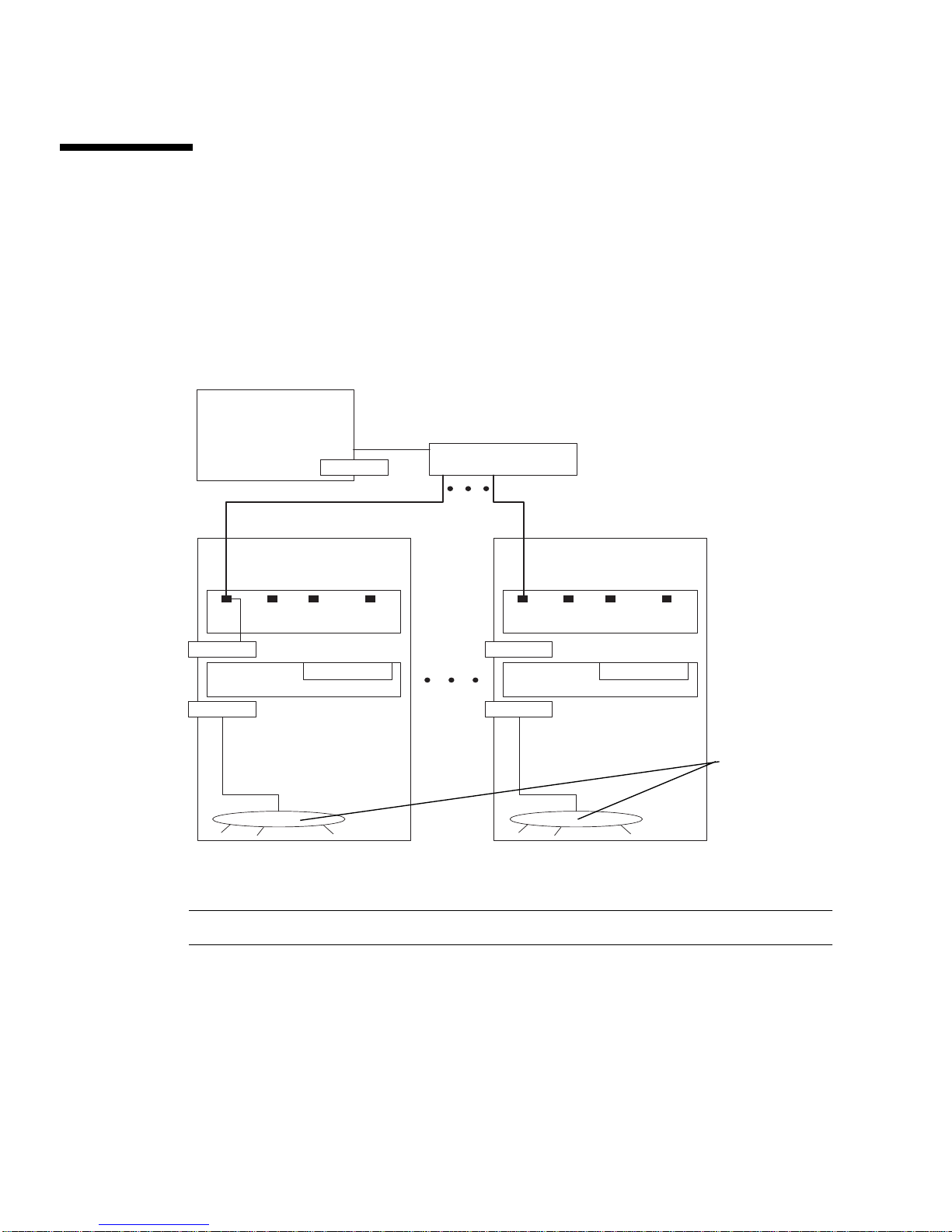
Multiple Units With No Remote Service
This configuration provides no remote services but does give the customer a
collection of Storage Service Processors.
It is recommended that the first Storage Service Processor be configured as the
master Storage Service Processor. If it can not be determined which is the first
Storage Service Processor, one should be selected by agreement of the customer and
Sun service engineer.
Application
Server (Host)
Ethernet hub LAN
Service Panel Service Panel
Storage Service Processor Storage Service Processor
FIGURE 4-1 Multiple Units Without the Sun StorEdge Remote Response Option
Note – Without remote connection, the Ethernet hub can be used in place of routers.
The following are supported features in this configuration:
■ Storage Automated Diagnostic Environment
■ Management of components using the “Configuration Utilities” on page 45
■ Local/host access to monitoring, component management, and alerts
40 Sun StorEdge 3900 and 6900 Series Reference Manual • February 2002
Component
Net
Page 59
■ Host-based diagnostic/monitoring agents (for example, topology)
■ Aggregation of Storage Service Processors
■ Multiple customer IP addresses required (one per Storage Service Processor)
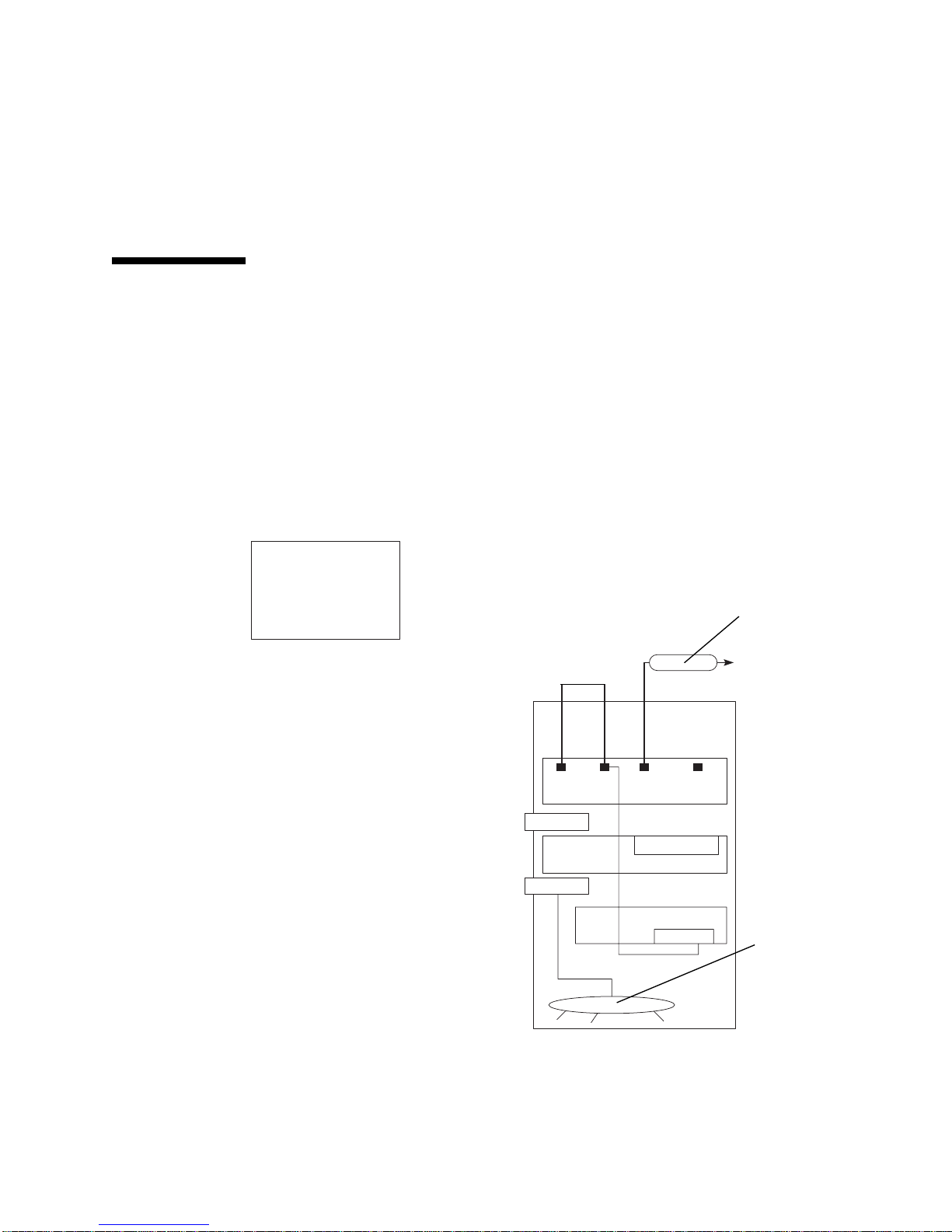
Remote Service to a Single Unit With No
Host Connection
This configuration offers remote service to a single Storage Service Processor. There
is no aggregation of Storage Server Processors. This configuration does not support
connection to a customer host.
In any configuration implementing remote service, the Storage Service Processor
attached to port 2 of the network terminal concentrator is the master Storage Service
Processor.
Application
Server (Host)
Ethernet hub LAN
Service Panel
Storage Service Processor
NTC
FIGURE 4-2 Remote Service to a Single Unit With No Host
Modem
Component
Net
Chapter 4 Configuration Features 41
Page 60

Supported features in this configuration are:
■ Storage Automated Diagnostic Environment
■ Management of components using the “Configuration Utilities” on page 45
■ Remote services (access to StorTools and Network Storage Agent)
■ Product telemetry data stream
■ Storage Service Processor serviceability using the console connection (NTC)
■ Telco rollover cable for connecting to components (NTC)
Remote Service to Multiple Units With
No Host Connection
This configuration offers remote service to multiple Storage Service Processor in the
configuration. No connection to the host is used.
42 Sun StorEdge 3900 and 6900 Series Reference Manual • February 2002
Page 61
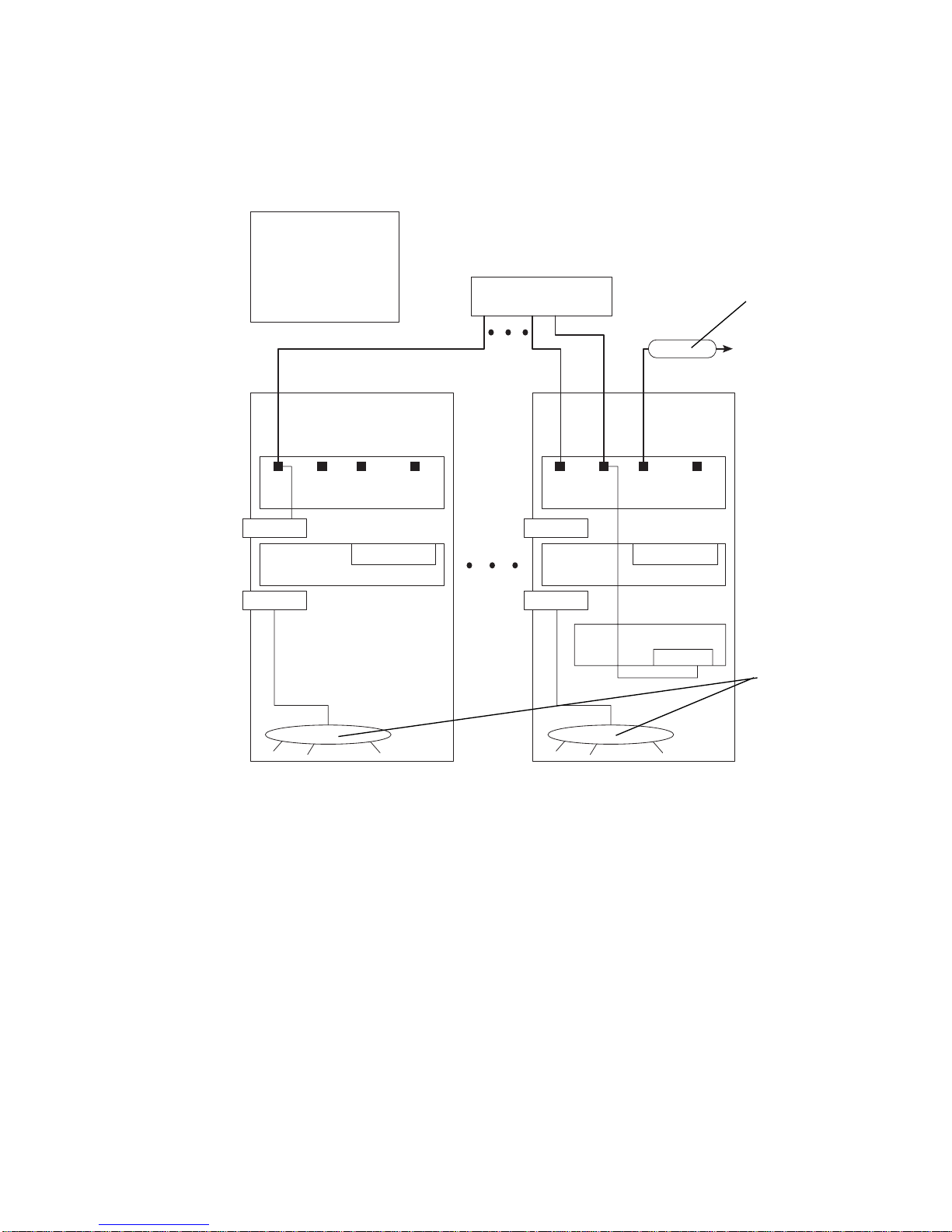
In any configuration implementing remote service, the Storage Service Processor
attached to port 2 of the network terminal concentrator is the master Storage Service
Processor.
Application
Server (Host)
Ethernet hub LAN
Modem
Service Panel
Storage Service Processor
Storage Service Processor
Service Panel
NTC
Component
Net
FIGURE 4-3 Remote Service to Multiple Units With No Host Connection
Supported features in this configuration are:
■ Storage Automated Diagnostic Environment
■ Management of components using the “Configuration Utilities” on page 45
■ Remote services (access to StorTools, Network Storage Agent, and alerts)
■ Product telemetry data stream
■ Storage Service Processor serviceability using the console connection (NTC)
■ Telco rollover cable for connecting to components (NTC)
■ Aggregation of Storage Service Processors
Chapter 4 Configuration Features 43
Page 62

44 Sun StorEdge 3900 and 6900 Series Reference Manual • February 2002
Page 63

CHAPTER
5
Configuration Utilities
This chapter gives instructions for using the command utilities that configure the
various components of the Sun StorEdge 3900 and 6900 series storage subsystems.
This chapter is organized as follows:
■ “Overview” on page 45
■ “Menu-Driven Interface” on page 46
■ “Command Line Interface” on page 75
Overview
You can use any of the following interfaces to access the configuration utilities:
■ Menu-driven character user interface
■ Command line
■ Configuration graphical user interface
There are five major functional categories:
■ Switch configuration
■ Sun StorEdge T3+ array configuration
■ Virtualization engine configuration
■ Log viewing
■ Error viewing
45
Page 64
Menu-Driven Interface
The menu-driven character user interface to the configuration utility is accessed
using the runsecfg(1M) command. This utility enables you to:
■ Configure, check, and display information about the attached Sun StorEdge T3+
partner groups.
■ Configure, check, and display information about the attached Sun switches.
■ Configure, check, and display information about the attached virtualization
engines.
■ Determine storage subsystem type and model number.
■ View detailed configuration utility messages in the log file.
■ View error log.
Caution – Do not run the Configuration Utilities at the same time you are using the
Storage Automated Diagnostic Environment diagnostics software.
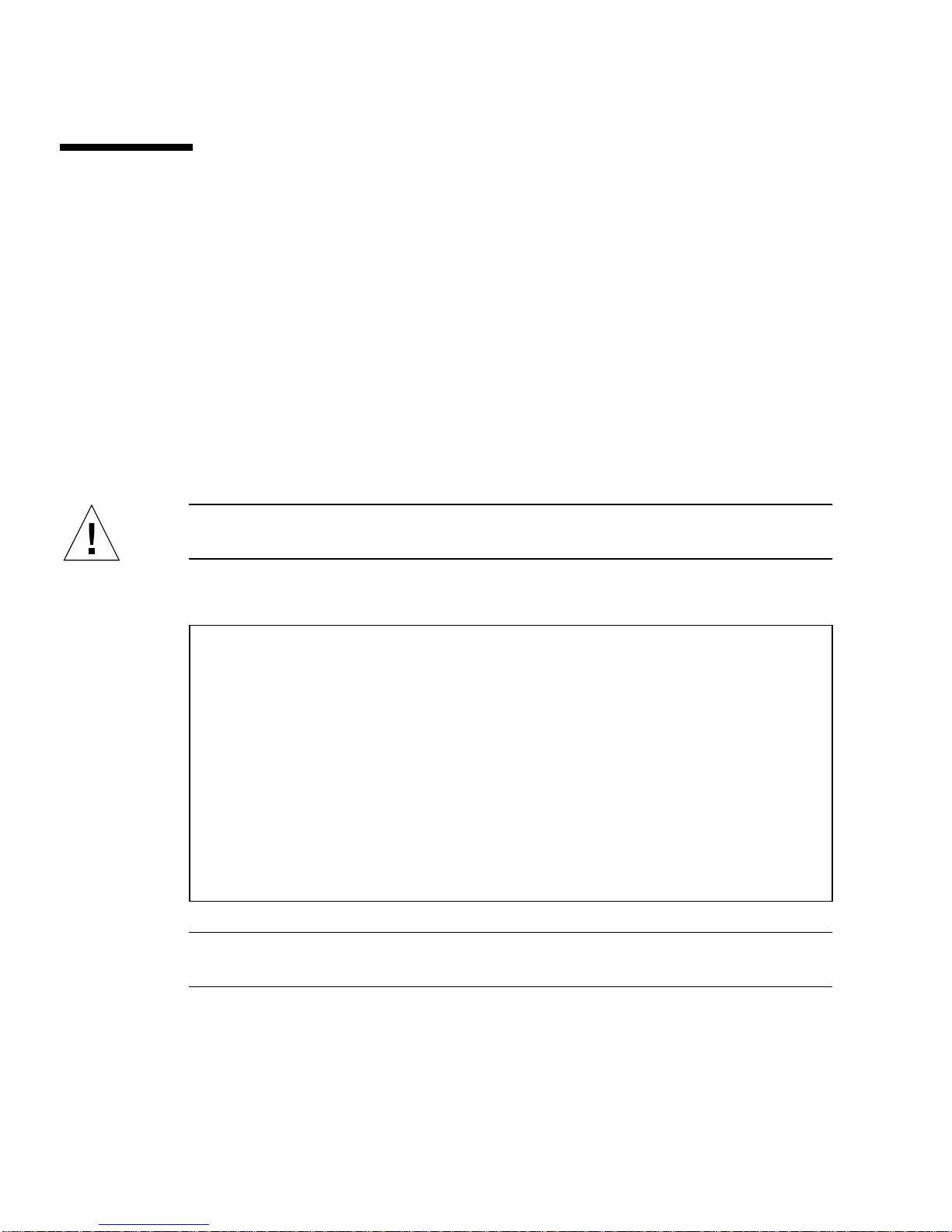
When started, runsecfg displays the following menu:
# runsecfg
Determining cabinet type...
MAIN MENU - SUN StorEdge 6960 SYSTEM CONFIGURATION TOOL
1) T3+ Configuration Utility
2) Switch Configuration Utility
3) Virtualization Engine Configuration Utility
4) View Logs
5) View Errors
6) Exit
Select option above:>
Note – If you have a Sun StorEdge 3900 series, you will not see the choice for the
Virtualization Engine Configuration Utility.
46 Sun StorEdge 3900 and 6900 Series Reference Guide • February 2002
Page 65

Sun StorEdge T3+ Array Main Menu
The Sun StorEdge T3+ array main menu presents the following choices. Note that
you are first prompted for the Sun StorEdge T3+ array password if one is set.
Retrieving list of available Sun StorEdge T3+ Array(s).........
Checking and validating PASSWD env variable for Sun StorEdge T3+
Array .........
Please enter the Sun StorEdge T3+ Array password : password
Validating Sun StorEdge T3+ Array password .........
Sun StorEdge T3+ Array MAIN MENU
1) Display Sun StorEdge T3+ Array Configuration
2) Save Sun StorEdge T3+ Array Configuration
3) Configure Sun StorEdge T3+ Array
4) Restore Sun StorEdge T3+ Array Configuration
5) Verify Sun StorEdge T3+ Array Configuration
6) Modify Sun StorEdge T3+ Array Sys Parameters
7) Display Sun StorEdge T3+ Array(s) Configuration Status
8) Help
9) Return
Select option above:>
■ Display Sun StorEdge T3+ Array Configuration—Reads and displays
configuration information for the specified Sun StorEdge T3+ array partner
group. It includes output from the following Sun StorEdge T3+ array commands:
■ ver
■ sys list
■ vol list
■ vol stat
■ port list
■ port listmap
■ fru stat
Chapter 5 Configuration Utilities 47
Page 66

When you select this option, you can select from a list of the Sun StorEdge T3+
array partner groups or select all partner groups, for example:
Busy Sun StorEdge T3+ Array(s)
-----------------------------NOTE : Currently NO Sun StorEdge T3+ Array(s) are being
configured/restored.
AVAILABLE Sun StorEdge T3+ Array(s)
1) t3b0
2) t3b1
3) ALL
4) Return
Select option above:> 2
t3b1 Properties.......
VERSION :-
T3B Release 2.00 2001/07/12 19:35:12 (192.168.0.41)
Copyright (C) 1997-2001 Sun Microsystems, Inc.
All Rights Reserved.
SYSTEM LISTING :-
blocksize : 16k
cache : auto
mirror : auto
mp_support : rw
naca : on
rd_ahead : off
recon_rate : med
sys memsize : 128 MBytes
cache memsize : 1024 MBytes
LUN LIST :-
volume capacity raid data standby
vol1 512.3 GB 5 u1d1-8 u1d9
vol2 512.3 GB 5 u2d1-8 u2d9
. . .
48 Sun StorEdge 3900 and 6900 Series Reference Guide • February 2002
Page 67

■ Save Sun StorEdge T3+ Array Configuration—Updates the Sun StorEdge T3+
array snapshot file after reading the array configuration. This information is
saved on the Storage Service Processor to be reused if needed, for example:
Busy Sun StorEdge T3+ Array(s)
-----------------------------NOTE : Currently NO Sun StorEdge T3+ Array(s) are being
configured/restored.
AVAILABLE Sun StorEdge T3+ Array(s)
1) t3b0
2) t3b1
3) ALL
4) Return
Select option above:> 2
Backing up Sun StorEdge T3+ Array configuration parameters to
Service Processor .....
Checking : t3b1 configuration.......
t3b1 Configuration matches with Standard config 1
Saving : t3b1 Properties.......
When you select this option, you can select from a list of the Sun StorEdge T3+
array partner groups or select all partner groups.
■ Configure Sun StorEdge T3+ Array— Steps you through a series of submenus
that enable you to reconfigure Sun StorEdge T3+ arrays. After successful update
of the configuration, the information is saved to the snapshot file. Supported
RAID types include: RAID 1, RAID 5, and RAID 1/RAID 5. In the RAID 1/RAID5
mixed RAID types, each Sun StorEdge T3+ array in the group has a RAID 1
device consisting of three physical drives and a RAID 5 device consisting of five
physical drives, plus a spare.
Chapter 5 Configuration Utilities 49
Page 68

When you select this option, you can select from a list of the Sun StorEdge T3+
array partner groups or select all partner groups.
AVAILABLE Sun StorEdge T3+ Array(s)
1) t3b0
2) t3b1
3) ALL
4) Return
Select option above:> 1
1) Default Config
2) Custom Config
3) Return to Sun StorEdge T3+ Array Menu
Select option above (t3b0):> 2
Sun StorEdge T3+ Array CONFIGURATION OPTION MENU
1) Raid 1
2) Raid 5
3) Raid 1 and Raid 5
4) Help
5) Return to Sun StorEdge T3+ Array Menu
Select configuration option above (t3b0):> 1
Sun StorEdge T3+ Array LUN OPTION MENU
1) 2
2) 4
3) Return to Sun StorEdge T3+ Array Menu
Select number of luns option above (t3b0):> 2
Sun StorEdge T3+ Array BLOCK SIZE OPTION MENU
1) 16k
2) 32k
3) 64k
4) Return to Sun StorEdge T3+ Array Menu
Select block size option above (t3b0):> 1
Sun StorEdge T3+ Array READ AHEAD OPTION MENU
1) on
2) off
3) Return to Sun StorEdge T3+ Array Menu
Select read ahead option above (t3b0):> 1
WARNING : You are about to destroy all the data on this Sun StorEdge
T3+ Array - t3b0 !!
Do you want to continue ?[yY] :
50 Sun StorEdge 3900 and 6900 Series Reference Guide • February 2002
Page 69

■ Restore Sun StorEdge T3+ Array Configuration—Restores the Sun StorEdge T3+
array configuration with the static saved configuration from the snapshot file.
This is a function that might be needed in the event you lose a LUN or you must
replace a Sun StorEdge T3+ array.
When you select this option you can select from a list of the Sun StorEdge T3+
array partner groups or select all partner groups.
Busy Sun StorEdge T3+ Array(s)
-----------------------------NOTE : Currently NO Sun StorEdge T3+ Array(s) are being configured/
restored.
AVAILABLE Sun StorEdge T3+ Array(s)
1) t3b0
2) t3b1
3) ALL
4) Return
Select option above:> 2
Sun StorEdge T3+ Array RESTORE LUN OPTION MENU
1) Lun 1
2) Lun 2
3) All Luns
4) Return to Sun StorEdge T3+ Array Menu
Select lun(s) to restore (t3b1):> 1
NOTE:
The restore option may destroy data on the lun(s) based on results
of the check operation. Do you want to FORCE a destructive
recreation of lun(s) even if the selected configuration is the same
as the saved configuration ?[y|n] : n
Sun StorEdge T3+ Array - t3b1 is being restored now.
NOTICE: This will take a minimum of approximately 2 hours!
Please view /var/adm/log/SEcfglog for more details and progress.
Please execute ’View Errors’ from the main menu to view errors
encountered.
After completion of t3b1 restoration,it will be available for
’Verify Sun StorEdge T3+ Array Configuration’.
Chapter 5 Configuration Utilities 51
Page 70

■ Verify Sun StorEdge T3+ Array Configuration— Verifies that the current Sun
StorEdge T3+ array configuration is the same as the most recently saved version
of the configuration in the snapshot file.
When you select this option, you can select from a list of the Sun StorEdge T3+
array partner groups or select all partner groups, for example:
Busy Sun StorEdge T3+ Array(s)
-----------------------------NOTE : Currently NO Sun StorEdge T3+ Array(s) are being configured/
restored.
AVAILABLE Sun StorEdge T3+ Array(s)
1) t3b0
2) t3b1
3) ALL
4) Return
Select option above:> 2
Checking : t3b1 Configuration.......
Checking command ver : PASS
Checking command vol stat : PASS
Checking command port list : PASS
Checking command port listmap : PASS
Checking command sys list : PASS
You are returned to the Main Menu.
52 Sun StorEdge 3900 and 6900 Series Reference Guide • February 2002
Page 71

■ Modify Sun StorEdge T3+ Array Sys Parameters—Enables changing the read
ahead (rd_ahead) parameter on both the Sun StorEdge 3900 or 6900 series
subsystems. On the Sun StorEdge 3900 series subsystems, you can also change the
naca and mp_support parameters.
AVAILABLE Sun StorEdge T3+ Array(s)
1) t3b0
2) t3b1
3) ALL
4) Return
Select option above:> 1
Do you want to modify the read ahead option [y|n] : y
Sun StorEdge T3+ Array READ AHEAD OPTION MENU
1) on
2) off
3) Return to Sun StorEdge T3+ Array Menu
Select read ahead option above (t3b0 Sun StorEdge T3+ Array(s)):> 2
Modifying t3b0 system parameters
Setting read_ahead flag to off
Current t3b0 system parameters :-
blocksize : 16k
cache : auto
mirror : auto
mp_support : rw
naca : off
rd_ahead : off
recon_rate : med
sys memsize : 128 MBytes
cache memsize : 1024 MBytes
■ Display Sun StorEdge T3+ Array(s) Configuration Status—Displays the name of
the Sun StorEdge T3+ arrays that are being configured or restored. If none are
being configured or restored, the following message is displayed and you are
returned to the Main Menu.
Currently NO Sun StorEdge T3+ Arrays are being configured or
restored.
Chapter 5 Configuration Utilities 53
Page 72

■ Help—Displays information that explains all the options.
■ Return—Returns you to the Main Menu.
Sun StorEdge Network FC Switch Main Menu
Note – Cascaded switches are supported in a SAN environment, but the runsecfg
utility cannot configure switches outside of the Sun StorEdge 6900 series cabinet.
Instead you must use the SANSurfer utility to create the appropriate hard zone and
to set unique chassis IDs on the other switches.
The Switch Main Menu presents the following options:
SWITCH MAIN MENU
1) Display Switch Configuration
2) Verify Switch Configuration
3) Set Switch Configuration
4) Download Switch Flash
5) Set Switch Port SL Mode Per Sun StorEdge T3+ Array
6) Help
7) Return
Select option above:>
■ Display Switch Config—Displays the specified switch’s configuration including
the following:
■ IP address configuration
■ Number of ports
■ Version information
■ Port status and type
■ Zones
54 Sun StorEdge 3900 and 6900 Series Reference Guide • February 2002
Page 73
When you select this option, you can select from a list of the Sun StorEdge
network FC switches or select all switches, for example:
AVAILABLE SWITCHES
1) sw1a
2) sw1b
3) sw2a
4) sw2b
5) ALL
6) Return
Select option above:>
You will see the sw2a and sw2b switches if you are running the runsecfg
command from a Sun StorEdge 6900 series.
Chapter 5 Configuration Utilities 55
Page 74

Selecting a switch returns all the configuration information about that switch, for
example:
Select option above:> 1
SWITCH: sw1a
Number of Ports: 8
IP Address: 192.168.0.30
*************************
IP Address Configuration
*************************
Net IP Address: 192.168.0.30
Net Mask: 255.255.255.0
Broadcast: 0.0.0.0
Gateway: 192.168.0.1
Address Discovery: RARP
ArpTimeOut: 30000
********************
Version Information
********************
HW: 1003
PROM: 30300
FLASH: 30462
CHASSIS TYPE: A8
CHASSIS NUMBER: 1
Fabric Id: 1
WWN: 100000c0dd009c54
MAC: 00c0dd009c53
...
■ Verify Switch Config—Verifies that the configuration of the specified switch
matches the predefined static configuration for that switch based on the cabinet
type (Sun StorEdge 3900 series or Sun StorEdge 6900 series).
56 Sun StorEdge 3900 and 6900 Series Reference Guide • February 2002
Page 75
When you select this option, you can select from a list of the Sun StorEdge FC
Network Switches or select all switches.
AVAILABLE SWITCHES
1) sw1a
2) sw1b
3) sw2a
4) sw2b
5) ALL
6) Return
Select option above:> 1
PASSED verification on switch sw1a, no differences found.
■ Set Switch Config—Configures the specified switch to a predefined static
configuration based on cabinet type and location (top or bottom switch for Sun
StorEdge 6900 series subsystems). For cascaded SAN environments you may
override the default values for hard zone IDs and chassis IDs. The following is
example output:
WARNING: Modifying the switch configuration may disrupt traffic.
Do you want to continue? [y n] y
AVAILABLE SWITCHES
1) sw1a
2) sw1b
3) sw2a
4) sw2b
5) ALL
6) Return
Select option above:> 1
Do you want to override the default zone number (1) [y|n] : n
Default chassis id = 1. Do you want to override the default chassis
id [y|n] : n
Configuring switch sw1a to default configuration...
setupswitch: sw1a INFO, switch FLASH VERSION is 30462.
PASSED verification on switch sw1a, no differences found.
setupswitch: sw1a INFO All switch settings properly set.
Chapter 5 Configuration Utilities 57
Page 76

An example of a predefined configuration follows.
Sun StorEdge 3910 system (DAS)
Basic
2 switches, same configuration
8 port switch
IP addresses (192.168.0.30, 192.168.0.31)
gateway IP address (192.168.0.1)
associated switch names (sw1a, sw1b)
associated chassis ids (1, 2)
Port/Zone Settings
Four Hard Zones
8 PORT
ZONE 1
Ports 1 = TL (t3b0 attach)
Ports 2 = F (Host attach)
ZONE 2
Ports 3 = TL (t3b1 attach)
Ports 4 = F (Host attach)
ZONE 3
Ports 5 = TL (t3b2 attach)
Ports 6 = F (Host attach)
ZONE 4
Ports 7 = TL (t3b3 attach)
Ports 8 = F (Host attach)
■ Set Switch Port SL Mode Per Sun StorEdge T3+ Array—Sets the switch ports
associated with the specified Sun StorEdge T3+ array to SL mode. If on is
selected, it sets all ports in the corresponding zone on each switch to SL mode. If
off is specified, it clears the SL mode and sets the ports back to the predefined
configuration.
58 Sun StorEdge 3900 and 6900 Series Reference Guide • February 2002
Page 77

This option is available for the Sun StorEdge 3900 series subsystems only. The last
two zones on a Sun StorEdge 3960 system contains two Sun StorEdge T3+ arrays
that can not be separated.
Available Port Settings
1) SL Mode
2) Default Modes (F and TL)
3) Return
Select option above:> 2
Retrieving list of available Sun StorEdge T3+ Array(s).........
AVAILABLE Sun StorEdge T3+ Array(s)
1) t3b0
2) t3b1
3) Return
Select option above:> 2
Setting ports associated with T3+ t3b1 back to default config.
Setting port 3 on sw1a to TL mode
Setting port 4 on sw1a to F mode
Setting port 3 on sw1b to TL mode
Setting port 4 on sw1b to F mode
■ Download Switch Flash—Downloads the flash code to the Sun StorEdge
Network FC Switch-8 or Switch-16 switch and resets it. The flash code is
automatically loaded from the appropriate file from the
/usr/opt/SUNWsmgr/flash directory unless an alternate file is specified at the
prompt. The currently released flash revision is 30462.
If you want to use another flash version, you are given the option to enter the
path to that version when you select this option:
Do you want to use the default flash file version 30462 ? [y|n]:y
■ Help—Displays information that explains all the options.
■ Return—Returns you to the Main Menu.
Chapter 5 Configuration Utilities 59
Page 78

Virtualization Engine Main Menu
The virtualization engine main menu presents the following options:
Determining the virtualization engine pairs on the system ......
VIRTUALIZATION ENGINE MAIN MENU
1) Manage VLUNs
2) Manage Virtualization Engine Zones
3) Manage Configuration Files
4) Manage Virtualization Engine Hosts
5) Help
6) Return
Select option above:>
■ Manage VLUNs—Enables you to create and remove VLUNs. The options on the
submenus include:
MANAGE VLUNs MENU
1) Create VLUNs
2) Remove VLUNs
3) View Virtualization Engine Map
4) Help
5) Return
Select VLUN option above:>
60 Sun StorEdge 3900 and 6900 Series Reference Guide • February 2002
Page 79

■ Create VLUNs—Enables you to create VLUNs. You are presented with a listing
of the available virtualization engine pairs, for example:
BUSY VIRTUALIZATION ENGINE PAIRS
-------------------------------NOTE : Currently NO virtualization engine pair(s) are being
configured.
AVAILABLE VIRTUALIZATION ENGINE PAIRS
1) v1
2) v2
3) Return
Select option above:> 2
DISK POOLS (free space)
1) t3b10(474.2GB)
2) t3b11(477.2GB)
3) Return
Select option above:> 1
NOTE : Creation of each VLUN can take up to 1 minute.
Please enter the number of VLUN(s) that need to be created: 2
Please enter the size in GB for each VLUN (1 GB increments): 2
Do you want to specify the zones ? [y|n]: n
Do you want to specify a name for the VLUN ? [y|n]: y
Please enter a name for the VLUN (There is a max length of 10 chars
including a unique id prefix that will be added automatically):test
This functionality requires a check that T3+ physical lun is
mounted.
Please enter the Sun StorEdge T3+ Array password: password
Creating VLUN(s) on v2 ........
Checking that associated T3+ physical lun is mounted...
VLUN T16387 : Created successfully in diskpool t3b10 with name
1test.
VLUN T16388 : Created successfully in diskpool t3b10 with name
2test.
NOTE: Updating map, v2 will be unavailable until completed.
WARNING: VLUNs just created were not added to any zones.
This should be done to avoid data corruption.
Refer to addtovezone command.
Chapter 5 Configuration Utilities 61
Page 80

■ Remove VLUNs—Enables you to remove VLUNs that have been created on
the virtualization engine pairs, for example:
BUSY VIRTUALIZATION ENGINE PAIRS
-------------------------------NOTE : Currently NO virtualization engine pair(s) are being
configured.
AVAILABLE VIRTUALIZATION ENGINE PAIRS
1) v1
2) v2
3) Return
Select option above:> 2
DISK POOLS (free space)
1) t3b10(470.2GB)
2) t3b11(477.2GB)
3) Return
Select option above:> 1
AVAILABLE VLUN TARGET ID(s)
1) T16384(1test)
2) T16385(2test)
3) T16386(redtest)
4) T16387(bluetest)
5) T16388(greentest)
6) Return
Select option above:> 4
Do you want to specify a range of target ids [y|n]: y
Please enter the end target id from the above VLUN list (i.e.
T16384): T16388
Removing VLUN(s) ........
VLUN T16387 : Removed successfully from v2.
VLUN T16388 : Removed successfully from v2.
NOTE: Updating map, v2 will be unavailable until completed.
62 Sun StorEdge 3900 and 6900 Series Reference Guide • February 2002
Page 81
■ Manage Virtualization Engine Zones—Presents the following options:
MANAGE ZONES MENU
1) Create Virtualization Engine Zone
2) Add Components to Virtualization Engine Zone
3) Delete Components from Virtualization Engine Zone
4) Remove Virtualization Engine Zone
5) View Virtualization Engine Map
6) Help
7) Return
Select zone option above:>
Chapter 5 Configuration Utilities 63
Page 82

■ Create Virtualization Engine Zones—Enables you to create a virtualization
engine zone. You are presented the following submenus, for example:
BUSY VIRTUALIZATION ENGINE PAIRS
-------------------------------NOTE : Currently NO virtualization engine pair(s) are being
configured.
AVAILABLE VIRTUALIZATION ENGINE PAIRS
1) v1
2) v2
3) Return
Select option above:> 2
AVAILABLE VIRTUALIZATION ENGINE INITIATORS
1) I00001
2) I00002
3) Return
Select option above:> 1
AVAILABLE WWN NUMBERS
1) 210000E08B04E70F
2) Return
Select option above:> 1
Please enter the zone name (Recommendation : host_channelID , Note
: There is a max length of 15 chars for the zone name): ztest
Creating Virtualization Engine zone ........
HBA alias ztest : Created successfully.
Zone ztest : Created successfully on v2 initiator I00001.
NOTE: Updating map, v2 will be unavailable until completed.
64 Sun StorEdge 3900 and 6900 Series Reference Guide • February 2002
Page 83

■ Add Components to Virtualization Engine Zones—Add additional
components to an existing virtualization engine zone. You are presented with
the following submenus, for example:
AVAILABLE VIRTUALIZATION ENGINE INITIATORS
1) I00001
2) I00002
3) Return
Select option above:> 1
AVAILABLE ZONES FOR I00001
1) zone1
2) Return
Select option above:> 1
Do you want to add to secondary zone ?[y|n]: y
AVAILABLE ZONES FOR I00002
1) zone2
2) Return
Select option above:> 1
AVAILABLE VLUN TARGET ID(s)
1) T16384(1test1)
2) T16385(2test1)
3) Return
Select option above:> 1
Do you want to specify a range of target ids [y|n]: y
Please enter the end target id from the above VLUN list (i.e.
T16384): T16385
Adding components to Virtualization Engine zone ........
VLUN T16384 : Added successfully to zone zone1.
VLUN T16384 : Added successfully to zone zone2.
VLUN T16385 : Added successfully to zone zone1.
VLUN T16385 : Added successfully to zone zone2.
NOTE: Updating map, v1 will be unavailable until completed.
Chapter 5 Configuration Utilities 65
Page 84

■ Delete Components from Virtualization Engine Zones —Remove
components from an existing virtualization engine zone. You are presented
with the following submenus, for example:
AVAILABLE VIRTUALIZATION ENGINE INITIATORS
1) I00001
2) I00002
3) Return
Select option above:> 1
AVAILABLE ZONES FOR I00001
1) zone1
2) Return
Select option above:> 1
Do you want to delete from secondary zone too?[y|n]: n
AVAILABLE VLUN TARGET ID(s)
1) T16384(1test1)
2) T16385(2test1)
3) Return
Select option above:> 1
Do you want to specify a range of target ids [y|n]: n
Deleting components from Virtualization Engine zone ........
VLUN T16384 : Deleted successfully from zone zone1.
NOTE: Updating map, v1 will be unavailable until completed.
66 Sun StorEdge 3900 and 6900 Series Reference Guide • February 2002
Page 85

■ Remove Virtualization Engine Zone—You can remove an entire virtualization
engine zone using this option, for example:
AVAILABLE VIRTUALIZATION ENGINE INITIATORS
1) I00001
2) I00002
3) Return
Select option above:> 1
AVAILABLE ZONES FOR I00001
1) zone1
2) rmzone
3) Return
Select option above:> 2
Removing Virtualization Engine zone ........
Zone rmzone : Removed successfully from v1 initiator I00001.
NOTE: Updating map, v1 will be unavailable until completed.
HBA alias rmzone : Cleared successfully.
■ View Virtualization Engine Map—Displays the current saved configuration
map of the specified virtualization engine (see page 71 for example output).
■ Manage Virtualization Engine Hosts—Presents the following options:
MANAGE VIRTUALIZATION ENGINE HOSTS MENU
1) Verify Virtualization Engine Hosts
2) Setup Virtualization Engine Hosts
3) Return
Select option above:>
Chapter 5 Configuration Utilities 67
Page 86

■ Verify Virtualization Engine Hosts—Verifies the specified virtualization
engine host is properly configured, for example:
AVAILABLE VIRTUALIZATION ENGINE HOSTS
1) v1a
2) v1b
3) ALL
4) Return
Select option above:> 1
Checking for VEPASSWD env variable ......
v1a login success
Verifying Virtualization Engine host v1a........
Reading v1a configuration
Router Management config
Host side WWN Authentications are set properly
Host IP Authentications are set properly
other VEHOST IP is set properly
Device side configuration
Operating Mode is set properly
UID reporting scheme is set properly
Host side configuration
Host side Operating Mode is set properly
LUN Mapping Mode is set properly
Command Queue Depth is set properly
UID distinguish is set properly
UID reporting scheme is set properly
Network Configuration
IP set properly
Sub net mask is properly
Default gateway set properly
Server port number is set properly
v1a configuration check passed
Virtualization Engine host v1a verified successfully.
68 Sun StorEdge 3900 and 6900 Series Reference Guide • February 2002
Page 87

■ Setup Virtualization Engine Hosts—Sets up the virtualization engine host, for
example:
AVAILABLE VIRTUALIZATION ENGINE HOSTS
1) v1a
2) v1b
3) ALL
4) Return
Select option above:> 2
Checking for VEPASSWD env variable ......
v1a login success
Verifying Virtualization Engine host v1b........
Reading v1b configuration
Router Management config
Host side WWN Authentications are set properly
Host IP Authentications are set properly
other VEHOST IP is set properly
Device side configuration
Operating Mode is set properly
UID reporting scheme is set properly
Host side configuration
Host side Operating Mode is set properly
LUN Mapping Mode is set properly
Command Queue Depth is set properly
UID distinguish is set properly
UID reporting scheme is set properly
Network Configuration
IP set properly
Sub net mask is properly
Default gateway set properly
Server port number is set properly
v1b configuration check passed
Virtualization Engine host v1b verified successfully. Setup is not
required.
Chapter 5 Configuration Utilities 69
Page 88
■ Manage Configuration Files —Gives you the following options:
MANAGE CONFIGURATION FILES MENU
1) Display Virtualization Engine Map
2) Save Virtualization Engine Map
3) Verify Virtualization Engine Map
4) Help
5) Return
Select configuration option above:>
70 Sun StorEdge 3900 and 6900 Series Reference Guide • February 2002
Page 89

■ Display Virtualization Engine Map —Displays the current configuration of the
specified virtualization engine, for example:
Do you want to poll from live system (time consuming) or view from the file
[l|f]: f
VIRTUAL LUN SUMMARY
Diskpool VLUN Serial MP Drive VLUN VLUN Size Slic Zones
Number Target Target Name GB
-----------------------------------------------------------------------------t3b00 6257334F3030364D T49156 T16384 VDRV000 477.0 zone1,zone2
t3b01 6257334F3030364E T49157 T16385 VDRV001 477.0 zone1,zone2
t3b10 6257334F3030364F T49152 T16386 VDRV002 9.0
t3b10 6257334F30303650 T49152 T16387 VDRV003 9.0
...
*****
DISKPOOL SUMMARY
Diskpool RAID MP Drive Size Free Space T3+ Active Number of
Target GB GB Path WWN VLUNs
----------------------------------------------------------------------t3b00 5 T49156 477.2 0.2 50020F2300002E60 1
t3b01 5 T49157 477.2 0.2 50020F230000ACFC 1
t3b10 1 T49152 272.7 254.7 50020F2300000970 2
...
*****
MULTIPATH DRIVE SUMMARY
Diskpool MP Drive T3+ Active Controller Serial
Target Path WWN Number
------------------------------------------------------t3b00 T49156 50020F2300002E60 60020F2000002E60
t3b01 T49157 50020F230000ACFC 60020F2000002E60
t3b10 T49152 50020F2300000970 60020F2000000970
...
*****
VIRTUALIZATION ENGINE SUMMARY
Initiator UID VE Host Online Revision Number of SLIC Zones
---------------------------------------------------------------------------I00001 290000602200418A v1a Yes 08.14 2
I00002 290000602200420C v1b Yes 08.14 2
*****
ZONE SUMMARY
Zone Name HBA WWN Initiator Online Number of VLUNs
--------------------------------------------------------------------zone1 210000E08B04465C I00001 Yes 2
zoneA 210000E08B042E80 I00001 Yes 0
Undefined 210100E08B24AA55 I00001 Yes 0
...
Chapter 5 Configuration Utilities 71
Page 90

■ Save Virtualization Engine Map—Saves the current configuration of the
specified virtualization engine, for example:
MANAGE CONFIGURATION FILES MENU
1) Display Virtualization Engine Map
2) Save Virtualization Engine Map
3) Verify Virtualization Engine Map
4) Help
5) Return
Select configuration option above:> 2
Saving Virtualization Engine map for v1........
Virtualization Engine map for v1 saved successfully.
■ Verify Virtualization Engine Map—Verifies that the live configuration of the
specified virtualization engine matches the saved configuration, for example:
MANAGE CONFIGURATION FILES MENU
1) Display Virtualization Engine Map
2) Save Virtualization Engine Map
3) Verify Virtualization Engine Map
4) Help
5) Return
Select configuration option above:> 3
Verifying Virtualization Engine map for v1........
checkvemap: VE map v1 verification complete: PASS.
Virtualization Engine map for v1 verified successfully.
■ Help—Displays information that explains all the options.
■ Return—Returns you to the Main Menu.
72 Sun StorEdge 3900 and 6900 Series Reference Guide • February 2002
Page 91
View Log Option
The View Log option on the Main Menu enables you to look at all the log entries or
just the most recent 50 lines. The log contains messages about the configuration
actions taken, for example:
...
Thu Nov 8 08:47:54 MST 2001 checkt3config: t3b0 EXIT: .
Thu Nov 8 08:52:07 MST 2001 showswitch: sw1a ENTER.
Thu Nov 8 08:52:08 MST 2001 showswitch: sw1a EXIT.
...
View Errors Option
The View Errors option on the Main Menu enables you to look at error messages.
The View Errors menu presents the following options:
VIEW ERRORS MENU
1) All Errors
2) Today’s Errors
3) Specific Date Errors
4) Return
Select option above:>
■ All Errors—Displays all the errors that have been recorded.
Chapter 5 Configuration Utilities 73
Page 92

■ Today’s Errors—Displays the errors that have been recorded since midnight in
your time zone, for example:
VIEW ERRORS MENU
1) All Errors
2) Today’s Errors
3) Specific Date Errors
4) Return
Select option above:> 2
TODAY’s ERRORS
------------------
Mon Jan 7 09:25:31 MST 2002 modifyt3config: t3b2 ERROR : While executing created
iskpools command /opt/SUNWsecfg/bin/creatediskpools: 29174 Terminated.
Mon Jan 7 09:25:30 MST 2002 modifyt3config: t3b0 ERROR : While executing created
iskpools command /opt/SUNWsecfg/bin/creatediskpools: 29574 Terminated.
Mon Jan 7 09:25:30 MST 2002 modifyt3config: t3b1 ERROR : While executing created
iskpools command /opt/SUNWsecfg/bin/creatediskpools: 28757 Terminated.
Mon Jan 7 09:29:29 MST 2002 checkslicd: ERROR Specified daemon for VE pair v1 wa
s not found.
Mon Jan 7 09:29:30 MST 2002 checkslicd: ERROR Specified daemon for VE pair v1 wa
s not found.
■ Specific Date Errors—Enables you to specify a date.
VIEW ERRORS MENU
1) All Errors
2) Today’s Errors
3) Specific Date Errors
4) Return
Select option above:> 3
Please enter first three characters of the month name :(Ex- : Nov) :Jan
Please enter the day of the month :(Ex- : 8 or 15) :9
Please enter the year (4 digit format) :(Ex- : 2001 or 2002) :2002
Wed Jan 9 14:46:42 MST 2002 rmdiskpools: v1 ERROR, Unable to remove mpdrive T491
52 from diskpool t3b00. VE command exited with error 2.
74 Sun StorEdge 3900 and 6900 Series Reference Guide • February 2002
Page 93

Command Line Interface
You might prefer to run the configuration utilities from the command line rather
than use the character user interface. The utilities for the maintenance of these
components in the Sun StorEdge 3900 and 6900 series storage subsystems are given
in the following subsections:
■ Storage Service Processor Global Commands
■ Storage Service Processor Sun StorEdge T3+ Array Commands
■ Storage Service Processor Switch Commands
■ Storage Service Processor Virtualization Engine Commands
Storage Service Processor Global Commands
The following are general utilities used to manage the Sun StorEdge 3900 and 6900
series storage subsystems.
The global Storage Service Processor commands are described briefly here. For a
complete description of a command and its function, refer to the individual man(1)
pages.
■ checkdefaultconfig(1M) - Checks all switches, virtualization engines, and
Sun StorEdge T3+ arrays in the Sun StorEdge 3900 and 6900 series subsystem
against factory-set configurations or the latest snapshot files.
■ getcabinet(1M) - Gets the cabinet configuration type for a Sun StorEdge 3900 or
6900 series configuration. The cabinet configuration type is based on the
components discovered in the cabinet. The types of cabinets returned are 3910,
3960, 6910, and 6960.
■ getipaddr(1M) - Gets and returns the IP address of a component.
■ listavailable(1M) - Provides a list of the available component names from the
/etc/hosts file for each Sun StorEdge 3900 or 6900 series storage subsystem.
The list varies, based on the system that is queried. Components that are offline or
busy are not listed.
■ removelocks(1M) - Removes all the configuration lock files. If the processes are
active, the locks will not be removed.
■ runsecfg(1M) - The menu-driven character user interface to the configuration
utility is accessed using the runsecfg command. Refer to “Menu-Driven
Interface” on page 46 for detailed information.
Chapter 5 Configuration Utilities 75
Page 94

■ setdefaultconfig(1M) - Sets all switches, virtualization engines, and Sun
StorEdge T3+ arrays in the Sun StorEdge 3900 or 6900 series storage subsystem to
the default configurations.
Caution – All data is destroyed when the setdefaultconfig command is
executed.
■ showerrors(1M) - Displays errors logged into the /var/adm/log/SEcfglog
log file.
■ showlogs(1M) - Displays either the complete log file or the number of lines
specified from the file, which is located in /var/adm/log/SEcfglog.
Storage Service Processor Sun StorEdge T3+
Array Commands
The commands in this subsection are used to manage the Sun StorEdge T3+ arrays
that are attached to the Sun StorEdge 3900 and 6900 series storage subsystems.
These utilities use a PASSWD environment variable as the Sun StorEdge T3+ array
password for telnet(1) session login. If this environment variable is not set, the
utility tries to log in without a password.
Note – If your passwords on the Sun StorEdge T3+ array are null, do not set this
variable. Also, only use this variable if you use the same password for each Sun
StorEdge T3+ array.
msp0# PASSWD=password
msp0# export PASSWD
If the environment variable is not set to the Sun StorEdge T3+ password, the
command fails.
The commands to configure the Sun StorEdge T3+ array are described briefly here.
For a complete description of a command and its function, refer to the individual
man(1) pages.
■ checkt3config(1M) - Checks the current Sun StorEdge T3+ array configuration
with the previously saved configuration. This checking is done by running the
Sun StorEdge T3+ array commands ver, vol list, vol stat, port list,
port listmap, sys list, and fru stat and comparing the output with the
previously stored configuration information. Any changes to the information are
reported.
76 Sun StorEdge 3900 and 6900 Series Reference Guide • February 2002
Page 95
■ modifyt3config(1M) - Configures Sun StorEdge T3+ arrays to user-specified
options and updates the configuration snapshot file.
■ modifyt3params(1M) - modifies the parameters of the Sun StorEdge T3+ arrays.
This command does not alter existing LUN configurations.
■ restoret3config(1M) - Restores Sun StorEdge T3+ array configurations with
static saved configurations from the snapshot file. This functionality might be
needed in case of loss of LUNs or the replacement of Sun StorEdge T3+ arrays.
The Sun StorEdge T3+ array configuration is restored to the previously saved
configuration.
By default, this utility compares the existing configuration with the saved one. If
they are identical, the saved configuration is not restored. If the configuration is
the same but the LUNs are in an unmounted state, the command will attempt to
mount the LUNs. If no checks with the saved configuration are needed, you must
specify the -f (force) option.
Caution – If a LUN is not mounted, restoret3config performs a mount on that
LUN. However, if any of the RAID configuration information is different, you might
lose data. To avoid this, run the checkt3config command to verify that the RAID
configuration has not changed before using the restoret3config command.
■ savet3config(1M) - Writes the latest information from the Sun StorEdge T3+
array into the snapshot file.
■ showt3(1M) - Reads and displays information from Sun StorEdge T3+ arrays.
showt3 uses some Sun StorEdge T3+ internal commands to obtain information.
The Sun StorEdge T3+ commands include vol list, vol stat, port list,
and port listmap.
Storage Service Processor Switch Commands
The following are utilities used to manage the Sun StorEdge network FC Switch-8
and Switch-16 switches that are used in Sun StorEdge 3900 and 6900 series storage
subsystems.
For a complete description of a command and its function, refer to the individual
man(1) pages.
■ checkswitch(1M) - Verifies that the current configuration on the switch matches
the predefined static configuration based on cabinet type and switch location.
■ setswitchflash(1M) - Downloads the flash code to the Sun StorEdge Network
FC Switch-8 or Switch-16 switch and resets it. The flash code is automatically
loaded from the appropriate file from the /usr/opt/SUNWsmgr/flash directory
unless an alternate file is specified with the -f option.
Chapter 5 Configuration Utilities 77
Page 96

■ setswitchsl(1M) - Given a Sun StorEdge T3+ array name setswitchsl
configures all switch ports in the associated zone on both switches (down both
paths) to be SL mode. This command can also be used to return ports to the
default setting. This command is valid only on Sun StorEdge 3900 series
subsystems.
■ setupswitch(1M) - Configures a switch with predefined static configuration
information, based on the type of Sun StorEdge 3900 or 6900 series configuration.
■ showswitch(1M) - Displays configuration information about a switch. The
information includes the following:
■ IP address configuration
■ Version
■ Port status and type
■ Zones
Storage Service Processor Virtualization Engine
Commands
The Sun StorEdge 6900 series configuration utilities discussed in this subsection are
used to change the configuration of the virtualization engine. The configuration
utilities can be accessed by the menu-driven interface or individually.
After the StorEdge 6900 series systems are powered on and tested, the default
settings of the virtualization engine can be changed to meet the SAN environment in
which the system is installed.
Some of these utilities use a VEPASSWD environment variable as the virtualization
engine password for telnet(1) session login. The commands that use the
VEPASSWD variable include checkve(1M), resetsandb(1M), resetve(1M),
setupve(1M), and restorevemap(1M). If this environment variable is not set,
these utilities try to log in without a password.
Note – If your passwords on the virtualization engines are null, do not set this
variable. Also, only use this variable if you use the same password for each
virtualization engine.
msp0# VEPASSWD=password
msp0# export VEPASSWD
If the environment variable is not set to the virtualization engine password, the
command fails.
78 Sun StorEdge 3900 and 6900 Series Reference Guide • February 2002
Page 97

The commands to configure the virtualization engine are described briefly here. For
a complete description of a command and its function, refer to the individual man(1)
pages.
■ addtovezone(1M) - Adds a VLUN to the virtualization engine name, initiator,
and zone name specified.
■ checkslicd(1M) - Verifies that the slicd daemon is running and
communicating with the virtualization engine
■ checkve(1M) - Checks the parameter settings of the virtualization engine. The
parameter settings include the Ethernet settings, host side settings, device side
settings, and SV management programs.
■ checkvemap(1M) - Verifies that the live configuration of the virtualization engine
matches the saved configuration for that virtualization engine.
■ creatediskpools(1M) - Creates disk pools that map to physical LUNs on the
specified Sun StorEdge T3+ array. These disk pools can then be used to create
VLUNs. This command is typically called by the modifyt3config command
and not run directly by the user.
■ createvezone(1M) - Creates an HBA alias and zone of the same name for the
virtualization engine, initiator, and WWN specified.
■ createvlun(1M) - Creates VLUNs for the virtualization engine, disk pool, size,
and number specified.
■ delfromvezone(1M) - Removes a VLUN from the zone specified by the
virtualization engine, initiator, and zone name specified.
■ getdpspace(1M) - Returns the available space in the disk pool in Gbytes.
■ listve(1M) - Returns a list of the specified virtualization engine components
that are found by querying the system.
■ listvemap(1M) - Returns a list of the specified virtualization engine components
from the configuration map file. This command provides better performance than
the listve command, if the virtualization engine map file is up to date.
■ resetsandb(1M) - Clears the SAN databases on the virtualization engines and
resets both engines.
■ resetve(1M) - Resets the specified virtualization engine.
■ restorevemap(1M) - Restores the configuration from the saved map file to the
specified virtualization engine.
■ rmdiskpools(1M) - Removes disk pools and all VLUNs in the disk pool for the
specified Sun StorEdge T3+ array LUNs. This command is typically used when
you are performing a reconfiguration of the Sun StorEdge T3+ array. This
command is typically called by the modifyt3config command and not run
directly by the user.
■ rmvezone(1M) - Removes the zone for the virtualization engine, initiator, and
zone name specified.
Chapter 5 Configuration Utilities 79
Page 98

■ rmvlun(1M) - Removes the VLUN for the virtualization engine, disk pool, and
VLUN target ID specified.
■ savet3map(1M) - Records all Sun StorEdge T3+ array configuration information
in a file that can be used by the virtualization engine.
■ savevemap(1M) - Saves the current configuration of the specified virtualization
engine in a map file.
■ setupve(1M) - Sets the parameters to the default values for the specified
virtualization engine. The parameter settings include the Ethernet, host side
settings, device side settings, and SV management programs.
■ showvemap(1M) - Displays the current configuration saved in the map file for the
specified virtualization engine.
■ startslicd(1M) - Starts the slicd daemon on the Storage Service Processor of
the Sun StorEdge 6900 series storage subsystem. The slicd provides the
communication channel between the virtualization engines and the Sun StorEdge
6900 series subsystems.
80 Sun StorEdge 3900 and 6900 Series Reference Guide • February 2002
Page 99

CHAPTER
6
Fault Detection and Isolation
Overview
This chapter provides a brief overview of the functionality provided when using the
Storage Automated Diagnostic Environment software to perform fault detection and
isolation on the Sun StorEdge 3900 and 6900 series subsystems.
For detailed instructions on configuring and using the Storage Automated
Diagnostic Environment, refer to the Storage Automated Diagnostic Environment User’s
Guide.
This chapter is organized as follows:
■ “Monitoring” on page 81
■ “Fault Detection” on page 82
■ “Fault Isolation” on page 83
Monitoring
If the customer’s host is part of the configuration, monitoring of the individual
components is done by Storage Automated Diagnostic Environment through the
out-of-band paths connected directly to the host server.
Out-of-band refers to the connections and devices that are not in the data path. The
Storage Service Processor does not have access to the data that is stored on the Sun
StorEdge 3900 and 6900 series storage subsystems.
81
Page 100

Fault Detection
The Storage Automated Diagnostic Environment software running on the Storage
Service Processor collects and evaluates information about devices out-of-band to all
storage devices in the Sun StorEdge 3900 and 6900 series cabinet.
One way in which the Storage Service Processor can have access to the in-band
diagnostic information is to have a Storage Automated Diagnostic Environment
software running on the customer host that relays information to the Storage Service
Processor so that it can send the information to Sun service for monitoring purposes.
Local Monitoring
The Storage Automated Diagnostic Environment software has the ability to be
configured to send alerts and events to a mail(1) address or even a pager address.
Customers not interested in remote monitoring or not concerned about security may
choose to allow local monitoring of the Sun StorEdge 3900 and 6900 series products
only. In this case, the customer has two choices:
■ Allow the Storage Service Processor to be connected to their management LAN
and have access to one or more of their host servers.
■ Provide a standalone workstation to be connected to the Storage Service Processor
as a dedicated resource that will be staffed 24 hours a day, 7 days a week.
If you already have a license for Sun Remote Services NetConnect service (SRS), you
can choose that method to pass alerts and event status messages to Sun. In that
situation, the Storage Automated Diagnostic Environment software is configured as
a slave on the Storage Service Processor. The master system running Storage
Automated Diagnostic Environment software is located on the host where SRS is
running. The slave sends all of its alert and event traffic over the customer’s
management LAN to the SRS host server for shipment to Sun. The master system
running the Storage Automated Diagnostic Environment software is optionally
configured to send email or pager messages locally.
If the customer uses the management LAN connection without host SRS support, the
Storage Automated Diagnostic Environment software can be set up to send email or
pager message notification when an alert or event occurs. To use this service, the
customer must allow access to a host server containing email or pager message
service. The Storage Automated Diagnostic Environment software on the Storage
Service Processor is then configured as a slave and send all of its alert and event
traffic to the master system running the Storage Automated Diagnostic Environment
software on the customer’s host server. The master system is responsible for
forwarding the traffic through the specified medium.
82 Sun StorEdge 3900 and 6900 Series Reference Manual • February 2002
 Loading...