


Sun Netra™X4450 Server
Service Manual
Sun Microsystems, Inc.
www.sun.com
Part No. 820-4017-10
August 2008, Revision A
Submit comments about this document at: http://docs.sun.com/app/docs

Copyright ©2008 Sun Microsystems, Inc., 4150 Network Circle,Santa Clara,California 95054, U.S.A.All rightsreserved.
Parts ofthe productmay be derived from BerkeleyBSD systems,licensed from the University ofCalifornia. UNIX is a registered trademark in
the U.S.and in other countries, exclusivelylicensed throughX/Open Company,Ltd.
Sun, SunMicrosystems, theSun logo, Java, Netra, Solaris,the Netra logo, the Solarislogo and Sun are trademarks or registered trademarksof
Sun Microsystems, Inc.in the U.S. and othercountries
All SPARCtrademarks areused under license and are trademarksor registeredtrademarks ofSPARCInternational, Inc. in the U.S.and other
countries. Products bearingSPARCtrademarks arebased upon architecture developed by Sun Microsystems, Inc.
Use ofany spareor replacementCPUs is limitedto repairor one-for-onereplacement ofCPUs in products exportedin compliancewith U.S.
export laws.Use of CPUs as product upgradesunless authorized by the U.S.Government isstrictly prohibited.
DOCUMENTATIONIS PROVIDED"AS IS" ANDALL EXPRESSOR IMPLIED CONDITIONS,REPRESENTATIONSAND WARRANTIES,
INCLUDING ANYIMPLIED WARRANTYOF MERCHANTABILITY,FITNESS FOR APARTICULAR PURPOSE OR NON-INFRINGEMENT,
ARE DISCLAIMED,EXCEPT TOTHE EXTENT THAT SUCHDISCLAIMERS ARE HELD TO BE LEGALLY INVALID.
Copyright ©2008 Sun Microsystems, Inc., 4150 Network Circle,Santa Clara,Californie 95054, États-Unis.Tous droits réservés.
Des partiesde ce produit peuvent dériver des systèmesBerkeley BSD licenciés par l’Universitéde Californie. UNIX est unemarque déposée
aux États-Uniset dans d’autres pays, licenciée exclusivement parX/Open Company, Ltd.
Sun, SunMicrosystems, lelogo Sun, Java, Netra, Solaris,le logo Netra, le logoSolaris et Sun sont desmarques defabrique ou des marques
déposées deSun Microsystems,Inc. aux Etats-Unis et dansd’autres pays.
Toutes lesmarques SPARC sont utilisées sous licenceet sont des marques de fabrique oudes marquesdéposées de SPARC International, Inc.
aux Etats-Uniset dans d’autres pays. Les produits portantles marquesSPARCsont basés sur une architecture développée par Sun
Microsystems, Inc.
L’utilisationde piecesdetachees ou d’unitescentrales deremplacement est limitee aux reparations oua l’echangestandard d’unites centrales
pour lesproduits exportes,conformement a la legislation americaineen matiered’exportation. Sauf autorisationpar lesautorites des EtatsUnis, l’utilisationd’unites centrales pour proceder a des misesa jour de produits estrigoureusement interdite.
LA DOCUMENTATION EST FOURNIE "ENL’ÉTAT" ETTOUTES AUTRESCONDITIONS, DÉCLARATIONS ET GARANTIES EXPRESSES
OU TACITES SONT FORMELLEMENTEXCLUES DANSLA LIMITE DE LA LOIAPPLICABLE, Y COMPRIS NOTAMMENTTOUTE
GARANTIE IMPLICITERELATIVEÀ LA QUALITÉMARCHANDE, ÀL’APTITUDE À UNE UTILISATION PARTICULIÈRE OU À
L’ABSENCEDE CONTREFAÇON.

Contents
Preface ix
1. Server Diagnostics 1–1
1.1 Fault on Initial Power Up 1–1
1.2 Server Diagnostics Overview 1–2
1.2.1 Memory Fault Handling 1–4
1.3 Using the Status Indicators to Identify the State of Devices 1–4
1.3.1 Hard Drive Indicators 1–8
1.3.2 Power Supply Indicators 1–9
1.3.3 Ethernet Port Indicators 1–10
1.4 Using the Service Processor Firmware for Diagnosis and Repair
Verification 1–11
1.5 Using the Solaris Predictive Self Healing Feature 1–12
1.5.1 Identifying PSH Detected Faults 1–13
1.6 Collecting Information From Solaris OS Files and Commands 1–15
▼ Check the Message Buffer 16
▼ View System Message Log Files 16
1.7 Additional Service Related Information 1–17
▼ Use the fmdump Command to Identify Faults 14
▼ Clear PSH Detected Faults 15
iii

2. Preparing for Service 2–1
2.1 Safety Information 2–1
2.1.1 Safety Symbols 2–2
2.1.2 Electrostatic Discharge Safety 2–2
2.1.2.1 Use an Antistatic Wrist Strap 2–2
2.1.2.2 Use an Antistatic Mat 2–2
2.2 Required Tools 2–3
2.3 Preparing for Component Replacement 2–3
▼ Power Off the Server 3
▼ Disconnect the Cables From the Server 4
▼ Remove the Server From the Rack 4
▼ Remove the Top Cover 5
▼ Remove the Air Baffle 6
▼ Remove the Memory Mezzanine 6
▼ Remove the PCI Mezzanine 7
3. Replacing Components 3–1
3.1 Replacing the Air Filter 3–2
▼ Remove the Air Filter 2
▼ Install the Air Filter 3
3.2 Replacing a Power Supply 3–4
▼ Remove a Power Supply 5
▼ Install a Power Supply 6
3.3 Replacing a Hard Drive 3–7
▼ Remove a Hard Drive 7
▼ Install a Hard Drive 10
3.4 Replacing the Optical Media Drive 3–11
▼ Remove the Optical Media Drive 11
▼ Install the Optical Media Drive 12
iv Sun Netra X4450 Server Service Manual • August 2008

3.5 Replacing FB-DIMMs 3–14
▼ Locate a Faulty FB-DIMM 17
▼ Remove FB-DIMMs 17
▼ Install FB-DIMMs 18
3.6 Replacing System Fan 0 3–20
▼ Remove System Fan 0 20
▼ Install System Fan 0 21
3.7 Replacing System Fan 1 3–22
▼ Remove System Fan 1 22
▼ Install System Fan 1 23
3.8 Replacing System Fan 2 3–24
▼ Remove System Fan 2 24
▼ Install System Fan 2 24
3.9 Replacing PCI Cards 3–25
3.9.1 Replace PCI-X and PCIe Cards in Slots 0-3 3–25
▼ Remove PCI-X and PCIe Cards in Slots 0-3 25
▼ Install PCI-X and PCIe Cards in Slot 0-3 27
3.9.2 Replacing PCI Cards in the PCI Mezzanine 3–28
▼ Remove PCI Cards in the PCI Mezzanine 28
▼ Install PCI Cards in the PCI Mezzanine 30
3.10 Replacing the System/Alarm LED Board 3–30
▼ Remove the System/Alarm LED Board 30
▼ Install the System/Alarm LED Board 31
3.11 Replacing the SAS Expander Card 3–32
▼ Remove the SAS Expander Card 32
▼ Install the SAS Expander Card 33
3.12 Replacing the Battery 3–35
▼ Remove the Battery 35
Contents v

▼ Install the Battery 36
3.13 Replacing the Motherboard Assembly 3–37
▼ Remove the Motherboard Assembly 37
▼ Install the Motherboard Assembly 40
3.14 Replacing the Power Board 3–43
▼ Remove the Power Board 44
▼ Install the Power Board 46
4. Returning the Server to Service 4–1
4.1 Returning the Server to Service 4–1
▼ Install the PCI Mezzanine 1
▼ Install the Memory Mezzanine 3
▼ Install the Air Baffle 4
▼ Install the Top Cover 4
▼ Reinstall the Server in the Rack 5
▼ Reconnect the Cables to the Server 5
▼ Power On the Server 6
A. Configuring BIOS and POST 5–7
A.1 Using BIOS Menu Items 5–7
▼ Access BIOS Configuration Screens and Change the System’s
Parameters 8
A.2 BIOS Considerations 5–8
A.2.1 Peripheral Component Interconnect (PCI) Card Slot Booting
Priority 5–8
A.2.2 Ethernet Port (NIC) Device and Driver Naming 5–9
A.2.3 NIC Naming 5–10
A.2.3.1 Sun Netra X4450 Server NIC Booting Priority 5–10
A.3 BIOS Setup Screens 5–11
A.3.1 BIOS Setup Menu Screens 5–12
vi Sun Netra X4450 Server Service Manual • August 2008

A.3.1.1 BIOS Main Menu Screens 5–13
A.3.1.2 BIOS Advanced Menu Screens 5–14
A.3.1.3 BIOS Boot Menu Screens 5–20
A.3.1.4 BIOS Server Menu Screens 5–23
A.3.1.5 BIOS Security Menu Screens 5–27
A.3.1.6 BIOS Exit Menu Screens 5–27
A.4 Viewing Event Logs 5–31
▼ View Event Logs 31
A.5 Power-On Self-Test (POST) 5–31
A.5.1 How BIOS POST Memory Testing Works 5–32
▼ Redirect Console Output 32
▼ Change POST Options 33
A.5.2 POST Codes 5–34
A.5.3 POST Code Checkpoints 5–36
B. Signal Pinouts A–1
A.1 Gigabit Ethernet Ports A–1
A.2 Network Management Port A–2
A.3 Serial Ports A–3
A.3.1 Serial Management Port A–3
A.3.1.1 RJ-45 to DB-9 Adapter Crossovers A–5
A.3.1.2 RJ-45 to DB-25 Adapter Crossovers A–5
A.3.2 Serial Port TTYA A–6
A.4 Alarm Port A–6
A.5 USB Ports A–7
Index Index–1
Contents vii

viii Sun Netra X4450 Server Service Manual • August 2008

Preface
This manual provides detailed procedures that describe the removal and
replacement of replaceable parts in the Sun Netra™ X4450 server. This manual also
includes detailed and comprehensive diagnostics information and procedures. This
document is written for technicians, system administrators, authorized service
providers (ASPs), and users who have advanced experience troubleshooting and
replacing hardware.
Related Documentation
The following table lists the documentation for this product. The online
documentation is available at:
http://docs.sun.com/app/docs/prod/server.nebs
Application Title
Installation Sun Netra X4450 Server Installation Guide 820-4015 PDF and
Issues and
updates
ILOM Reference Sun Integrated Lights Out Management 2.0
Sun Netra X4450 Server Product Notes 820-4018 PDF and
Supplement for the Sun Netra X4450 Server
Part
Number Format Location
Online
HTML
Online
HTML
820-5244 PDF and
HTML
Online
ix

Application Title
Part
Number Format Location
Platform safety
and compliance
Generic safety Important Safety Information for Sun Hardware
Sun Netra X4450 Server Safety and Compliance
Guide
Systems
820-4183 PDF and
HTML
816-7190 PDF and
printed
Online
Online and
shipping kit
Getting started Sun Netra Servers Getting Started Guide 820-3016 Printed Shipping kit
x Sun Netra X4450 Server Service Manual • August 2008

CHAPTER
1
Server Diagnostics
This chapter describes the diagnostics that are available for monitoring and
troubleshooting the server.
The following topics are covered:
■ Section 1.1 “Fault on Initial Power Up” on page 1-1
■ Section 1.2 “Server Diagnostics Overview” on page 1-2
■ Section 1.3 “Using the Status Indicators to Identify the State of Devices” on page
1-4
■ Section 1.4 “Using the Service Processor Firmware for Diagnosis and Repair
Verification” on page 1-11
■ Section 1.5 “Using the Solaris Predictive Self Healing Feature” on page 1-12
■ Section 1.6 “Collecting Information From Solaris OS Files and Commands” on
page 1-15
■ Section 1.7 “Additional Service Related Information” on page 1-17
1.1 Fault on Initial Power Up
If you have installed the server, and upon initial power up, you see errors indicating
faults with the Fully Buffered DIMMs (FB-DIMMs), PCI cards, or other components,
the suspect component might have become loose during shipment.
Conduct a visual inspection of the server internals and its components. Remove the
top cover and physically reseat the cable connections, the PCI cards, and the FBDIMMs.
1-1

1.2 Server Diagnostics Overview
There are a variety of diagnostic tools, commands, and indicators you can use to
monitor and troubleshoot a server:
■ Status indicators – These indicators provide a quick visual notification of the
status of the server and of some of the FRUs.
■ Fault management architecture – FMA provides simplified fault diagnostics
through use of the /var/adm/messages file, the fmdump command, and a Sun
Microsystems web site.
■ ILOM firmware – This system firmware runs on the service processor. In
addition to providing the interface between the hardware and OS, ILOM also
tracks and reports the health of key server components. ILOM works closely with
POST and Solaris™ Predictive Self Healing technology to keep the system up and
running even when there is a faulty component.
■ Power-on self-test (POST) – POST performs diagnostics on system components
upon system reset to ensure the integrity of those components. POST is
configurable and works with ILOM to take faulty components offline if needed.
■ Solaris Predictive Self-Healing (PSH) – This technology continuously monitors
the health of the CPU and memory, and works with ILOM to take a faulty
component offline if needed. The Predictive Self Healing technology enables
Sun™ systems to accurately predict component failures and mitigate many
serious problems before they occur.
■ Log files and console messages – These provide the standard Solaris Operating
System (OS) log files and investigative commands that can be accessed and
displayed on the device of your choice.
The LEDs, ILOM, Solaris PSH, and many of the log files and console messages are
integrated. For example, a fault detected by the Solaris software will display the
fault, log it, pass information to ILOM where it is logged, and, depending on the
fault, might light one or more LEDs.
1-2 Sun Netra X4450 Server Service Manual • August 2008

TABLE 1-1 Diagnostic Actions
Action
No. Diagnostic Action Resulting Action Additional Information
1 Check Power OK
and Input OK
LEDs on the server.
2 Check the Solaris
log files for fault
information.
3 Determine if the
fault is an
environmental
fault.
4 Determine if the
fault was detected
by PSH.
The Power OK LED is located on the front and rear
of the chassis.
The Input OK LED is located on the rear of the
server on each power supply.
If these LEDs are not on, check the power source
and power connections to the server.
The Solaris message buffer and log files record
system events and provide information about faults.
If system messages indicate a faulty device, replace
the FRU.
Environmental faults can be caused by faulty FRUs
(power supply, fan, or blower), or by environmental
conditions such as when computer room ambient
temperature is too high, or the server airflow is
blocked. When the environmental condition is
corrected, the fault will automatically clear.
If the fault indicates that a fan, blower, or power
supply is bad, you can perform a hot-swap of the
FRU. You can also use the fault indicators on the
server to identify the faulty FRU (fans, blower, and
power supplies).
If the fault message displays the following text, the
fault was detected by the Solaris Predictive Self
Healing software:
Host detected fault
Section 1.3 “Using the
Status Indicators to
Identify the State of
Devices” on page 1-4
Section 1.6 “Collecting
Information From Solaris
OS Files and Commands”
on page 1-15
Section 1.4 “Using the
Service Processor Firmware
for Diagnosis and Repair
Verification” on page 1-11
Section 1.3 “Using the
Status Indicators to
Identify the State of
Devices” on page 1-4
Section 1.5 “Using the
Solaris Predictive Self
Healing Feature” on page
1-12
If the fault is a PSH detected fault, identify the
faulty FRU from the fault message and replace the
faulty FRU.
After replacing the FRU, perform the procedure to
clear PSH detected faults.
5 Contact Sun for
Support.
The majority of hardware faults are detected by the
server’s diagnostics. In rare cases, a problem might
require additional troubleshooting. If you are unable
to determine the cause of the problem, contact Sun
for support.
“Clear PSH Detected
Faults” on page 1-15
Sun Support information:
http://www.sun.com/s
upport
Chapter 1 Server Diagnostics 1-3

1.2.1 Memory Fault Handling
The server uses an advanced ECC technology, called chipkill, that corrects up to 4
bits in error on nibble boundaries, as long as all of the bits are in the same DRAM. If
a DRAM fails, the FB-DIMM continues to function.
The Predictive Self Healing (PSH) technology in the Solaris OS uses the fault
manager daemon (fmd) to watch for various kinds of faults. When a fault occurs, the
fault is assigned a unique fault ID (UUID), and logged. PSH reports the fault and
provides a recommended proactive replacement for the FB-DIMMs associated with
the fault.
If you suspect that the server has a memory problem, see Section 3.5 “Replacing FB-
DIMMs” on page 3-14 for FB-DIMM replacement instructions. You must perform the
instructions in that chapter to clear the faults and enable the replaced FB-DIMMs.
1.3 Using the Status Indicators to Identify
the State of Devices
The server provides status indicators in the upper left corner of the front panel
(
FIGURE 1-1) and on the rear panel (FIGURE 1-2). These indicators provide a visual
means of determining the state of the system or individual components.
1-4 Sun Netra X4450 Server Service Manual • August 2008

FIGURE 1-1 Front Panel Status and Alarm Status Indicators
Figure Legend
1 White Locator Indicator and Button 5 Red Critical Alarm Indicator
2 Yellow Service Required Indicator 6 Red Major Alarm Indicator
3 Green Running Indicator 7 Amber Minor Alarm Indicator
4 On/Standby Button 8 Amber User Alarm Indicator
Chapter 1 Server Diagnostics 1-5

FIGURE 1-2 Rear Panel Status Indicators
Figure Legend
1 Alarm port 5 Management network port indicators
2 White Locator Indicator and button 6 Ethernet port indicators
3 Yellow Service Required Indicator 7 Power supply indicators
4 Green Running Indicator 8 Video port
1-6 Sun Netra X4450 Server Service Manual • August 2008

TABLE 1-2 lists and describes the front and rear panel indicators.
TABLE 1-2 Front and Rear Panel Indicators
LED Location Color Description
Locator
Indicator and
Button
Front upper
left and rear
left
Fault Indicator Front upper
center and
rear center
Activity
Indicator
Front upper
right andrear
right
Power Button Front upper
right
Power OK
Rear center Green Provides the following indications:
Indicator
White Enables you to identify a particular server. The LED is activated
using one of the following methods:
• Issuing the setlocator on or off command.
• Pressing the button to toggle the indicator on or off.
This LED provides the following indications:
• Off – Normal operating state.
• Fast blink – The server received a signal as a result of one of the
preceding methods.
Yellow If on, indicates that service is required.
Green • On – Drives are receiving power. Solidly on if drive is idle.
• Flashing – Drives are processing a command.
• Off – Power is off.
Turns the host system on and off. This button is recessed to prevent
accidental server power-off. Use the tip of a pen to operate this
button. Press this button once for a graceful shutdown. Press this
button for 4 seconds for an emergency shutdown.
• Off – The system is unavailable. Either the system has no power
or ILOM is not running.
• Steady on – Indicates that the system is powered on and is
running it its normal operating state.
• Standby blink – Indicates that the service processor is running
while the system is running at a minimum level in Standby
mode, and is ready to be returned to its normal operating state.
• Slow blink – Indicates that a normal transitory activity is taking
place. The system diagnostics might be running, or the system
might be booting.
Critical Alarm
Front left Red Indicates a critical alarm.
Indicator
Major Alarm
Front left Red Indicates a major alarm.
Indicator
Minor Alarm
Front left Amber Indicates a minor alarm.
Indicator
User Alarm
Front left Amber Indicates a user alarm.
Indicator
Chapter 1 Server Diagnostics 1-7

1.3.1 Hard Drive Indicators
The hard drive indicators (FIGURE 1-3 and TABLE 1-3) are located on the front of each
hard drive that is installed in the server chassis.
FIGURE 1-3 Hard Drive Indicators
Figure Legend
1 OK to Remove
2 Fault
3 Activity
TABLE 1-3 Hard Drive Indicators
Indicator Color Description
OK to
Remove
Blue • On – The drive is ready for hot-plug removal.
• Off – Normal operation.
Fault Amber • On – The drive has a fault and requires attention.
• Off – Normal operation.
Activity Green • On – The drive is receiving power. Solidly lit if drive is idle.
• Flashing – The drive is processing a command.
• Off – Power is off.
1-8 Sun Netra X4450 Server Service Manual • August 2008

1.3.2 Power Supply Indicators
The power supply indicators (FIGURE 1-4 and TABLE 1-4) are located on the rear of
each power supply.
Chapter 1 Server Diagnostics 1-9

FIGURE 1-4 Power Supply Indicators
Figure Legend
1 Power OK incdicator
2 Fault indicator
3 Input OK indicator
TABLE 1-4 Power Supply Indicators
Indicator Color Description
Power OK Green • On – Normal operation. DC output voltage is within normal
limits.
• Off – Power is off.
Fault Amber • On – Power supply has detected a failure.
• Off – Normal operation.
Input OK Green • On – Normal operation. Input power is within normal limits.
• Off – No input voltage, or input voltage is below limits.
1.3.3 Ethernet Port Indicators
The ILOM management Ethernet port and the four 10/100/1000 Mbps Ethernet
ports each have two indicators, as shown in
1-10 Sun Netra X4450 Server Service Manual • August 2008
FIGURE 1-5 and described in TABLE 1-5.

FIGURE 1-5 Ethernet Port Indicators
Figure Legend
1 Speed indicator (same location for all Ethernet ports)
2 Link/Activity indicator (Same location for all Ethernet ports)
TABLE 1-5 Ethernet Port Indicators
Indicator Color Description
Right
indicator
Left Indicator Amber
Green Link/Activity indicator:
• Steady On – a link is established.
• Blinking – there is activity on this port.
• Off – No link is established.
Speed indicator:
or Green
• Amber On – The link is operating as a Gigabit connection (1000Mbps)
• Green On – The link is operating as a 100-Mbps connection.
• Off – The link is operating as a 10/100-Mbps connection.
Note – The NET MGT port operates only in 100-Mbps or 10-Mbps so the speed
indicator can be green or off (never amber).
1.4 Using the Service Processor Firmware
for Diagnosis and Repair Verification
The Sun Integrated Lights Out Manager (ILOM) firmware is a service processor in
the server that enables you to remotely manage and administer your server.
Chapter 1 Server Diagnostics 1-11

ILOM enables you to remotely run diagnostics that would otherwise require
physical proximity to the server’s serial port. You can also configure ILOM to send
email alerts of hardware failures, hardware warnings, and other events related to the
server or to ILOM.
Faults detected by ILOM, POST, and the Solaris Predictive Self Healing (PSH)
technology are forwarded to ILOM for fault handling. In the event of a system fault,
ILOM ensures that the Fault Indicator is lit, the FRU ID PROMs are updated, the
fault is logged, and alerts are displayed (faulty FRUs are identified in fault messages
using the FRU name).
The service processor detects when a fault is no longer present and clears the fault in
several ways:
■ Fault recovery – The system automatically detects that the fault condition is no
longer present. ILOM extinguishes the Service Required Indicator and updates
the FRU’s PROM, indicating that the fault is no longer present.
■ Fault repair – The fault has been repaired by human intervention. In most cases,
the service processor detects the repair and extinguishes the Service Required
Indicator. If the service processor does not perform these actions, you must
perform these tasks manually.
The service processor also detects the removal of a FRU, in many cases even if the
FRU is removed while the service processor is powered off (that is, if the system
power cables are unplugged during service procedures). This situation enables
ILOM to know that a fault, diagnosed to a specific FRU, has been repaired.
Note – ILOM does not automatically detect hard drive replacement.
Many environmental faults can automatically recover. A temperature that is
exceeding a threshold might return to normal limits. An unplugged power supply
can be plugged in, and so on. Recovery of environmental faults is automatically
detected. Recovery events are reported using one of two forms:
■ fru at location is OK.
■ sensor at location is within normal range.
Environmental faults can be repaired through hot-removal of the faulty FRU. FRU
removal is automatically detected by the environmental monitoring, and all faults
associated with the removed FRU are cleared. The message for that case, and the
alert sent for all FRU removals is:
fru at location has been removed.
There is no ILOM command to manually repair an environmental fault.
1-12 Sun Netra X4450 Server Service Manual • August 2008

The Solaris Predictive Self Healing technology does not monitor the hard drive for
faults. As a result, the service processor does not recognize hard drive faults, and
will not light the fault indicators on either the chassis or the hard drive itself. Use the
Solaris message files to view hard drive faults. See Section 1.6 “Collecting
Information From Solaris OS Files and Commands” on page 1-15.
1.5 Using the Solaris Predictive Self Healing
Feature
The Solaris Predictive Self Healing (PSH) technology enables the server to diagnose
problems while the Solaris OS is running, and mitigate many problems before they
negatively affect operations.
The Solaris OS uses the fault manager daemon, fmd(1M), which starts at boot time
and runs in the background to monitor the system. If a component generates an
error, the daemon handles the error by correlating the error with data from previous
errors and other related information to diagnose the problem. After diagnosed, the
fault manager daemon assigns the problem a Universal Unique Identifier (UUID)
that distinguishes the problem across any set of systems. When possible, the fault
manager daemon initiates steps to self-heal the failed component and take the
component offline. The daemon also logs the fault to the syslogd daemon and
provides a fault notification with a message ID (MSGID). You can use the message
ID to get additional information about the problem from Sun’s knowledge article
database.
The Predictive Self Healing technology covers the following server components:
■ Processor
■ Memory
■ I/O bus
The PSH console message provides the following information:
■ Type
■ Severity
■ Description
■ Automated response
■ Impact
■ Suggested action for system administrator
If the Solaris PSH facility detects a faulty component, use the fmdump command to
identify the fault. Faulty FRUs are identified in fault messages using the FRU name.
Chapter 1 Server Diagnostics 1-13

Note – Additional Predictive Self Healing information is available at:
http://www.sun.com/msg
1.5.1 Identifying PSH Detected Faults
When a PSH fault is detected, a Solaris OS console message similar to
CODE EXAMPLE 1-1 is displayed.
CODE EXAMPLE 1-1 Console Message Showing Fault Detected by PSH
SUNW-MSG-ID: SUN4V-8000-DX, TYPE: Fault, VER: 1, SEVERITY: Minor
EVENT-TIME: Wed Sep 14 10:09:46 EDT 2005
PLATFORM: SUNW,Sun-Netra-X4450, CSN: -, HOSTNAME: wgs48-37
SOURCE: cpumem-diagnosis, REV: 1.5
EVENT-ID: f92e9fbe-735e-c218-cf87-9e1720a28004
DESC: The number of errors associated with this memory module has exceeded
acceptable levels. Refer to http://sun.com/msg/SUN4V-8000-DX for more
information.
AUTO-RESPONSE: Pages of memory associated with this memory module are being
removed from service as errors are reported.
IMPACT: Total system memory capacity will be reduced as pages are retired.
REC-ACTION: Schedule a repair procedure to replace the affected memory module.
Use fmdump -v -u <EVENT_ID> to identify the module.
Faults detected by the Solaris PSH facility are also reported through service
processor alerts.
Note – The Service Required Indicator is also turned on for PSH diagnosed faults.
▼ Use the fmdump Command to Identify Faults
The fmdump command displays the list of faults detected by the Solaris PSH facility
and identifies the faulty FRU for a particular EVENT_ID (UUID).
Do not use fmdump to verify a FRU replacement has cleared a fault because the
output of fmdump is the same after the FRU has been replaced. Use the fmadm
faulty command to verify the fault has cleared.
1. Check the event log using the fmdump command with -v for verbose output.
The output includes the following details:
■ Date and time of the fault (Jul 31 12:47:42.2007)
1-14 Sun Netra X4450 Server Service Manual • August 2008

■ Universal Unique Identifier (UUID). This is unique for every fault
(fd940ac2-d21e-c94a-f258-f8a9bb69d05b)
■ Sun message identifier, which can be used to obtain additional fault
information (SUN4V-8000-JA)
■ Faulted FRU. The information provided in the example includes the part
number of the FRU (part=541215101) and the serial number of the FRU
(serial=101083). The Location field provides the name of the FRU. The
FRU name is MB, meaning the motherboard.
Note – fmdump displays the PSH event log. Entries remain in the log after the fault
has been repaired.
2. Use the Sun message ID to obtain more information about this type of fault.
a. In a browser, go to the Predictive Self Healing Knowledge Article web site:
http://www.sun.com/msg
b. Obtain the message ID from the console output.
c. Enter the message ID in the SUNW-MSG-ID field, and click Lookup.
3. Follow the suggested actions to repair the fault.
Chapter 1 Server Diagnostics 1-15

▼ Clear PSH Detected Faults
When the Solaris PSH facility detects faults the faults are logged and displayed on
the console. In most cases, after the fault is repaired, the corrected state is detected
by the system and the fault condition is repaired automatically. However, this must
be verified and, in cases where the fault condition is not automatically cleared, the
fault must be cleared manually.
1. After replacing a faulty FRU, power on the server.
2. Clear the fault from all persistent fault records.
In some cases, even though the fault is cleared, some persistent fault information
remains and results in erroneous fault messages at boot time. To ensure that these
messages are not displayed, perform the following Solaris OS command:
fmadm repair UUID
For example:
# fmadm repair 7ee0e46b-ea64-6565-e684-e996963f7b86
1.6 Collecting Information From Solaris OS
Files and Commands
With the Solaris OS running on the server, you have the full complement of Solaris
OS files and commands available for collecting information and for troubleshooting.
If the service processor or the Solaris PSH features do not indicate the source of a
fault, check the message buffer and log files for notifications for faults. Hard drive
faults are usually captured by the Solaris message files.
Use the dmesg command to view the most recent system message. To view the
system messages log file, view the contents of the /var/adm/messages file.
1-16 Sun Netra X4450 Server Service Manual • August 2008

▼ Check the Message Buffer
1. Log in as superuser.
2. Type the dmesg command:
# dmesg
The dmesg command displays the most recent messages generated by the
system.
▼ View System Message Log Files
The error logging daemon, syslogd, automatically records various system
warnings, errors, and faults in message files. These messages alert you to system
problems such as a device that is about to fail.
The /var/adm directory contains several message files. The most recent messages
are in the /var/adm/messages file. After a period of time (usually every ten days),
a new messages file is automatically created. The original contents of the
messages file are rotated to a file named messages.1. Over a period of time, the
messages are further rotated to messages.2 and messages.3, and then deleted.
1. Log in as superuser.
2. Type:
# more /var/adm/messages
3. If you want to view all logged messages, type:
# more /var/adm/messages*
Chapter 1 Server Diagnostics 1-17

1.7 Additional Service Related Information
In addition to this service manual, the following resources are available to help you
keep your server running optimally:
■ Server Product Notes – Contain late-breaking information about the system
including required software patches, updated hardware and compatibility
information, and solutions to know issues. The product notes are available online
at: http://docs.sun.com
■ Solaris Release Notes – Contain important information about the Solaris OS. The
release notes are available online at: http://docs.sun.com
■ SunSolve™ Online – Provides a collection of support resources. Depending on
the level of your service contract, you have access to Sun patches, the Sun System
Handbook, the SunSolve knowledge base, the Sun Support Forum, and additional
documents, bulletins, and related links. Access this site at:
http://sunsolve.sun.com
■ Predictive Self Healing Knowledge Database – Provides access to the
knowledge article corresponding to a self-healing message by taking the Sun
Message Identifier (SUNW-MSG-ID) and entering it into the field on this page:
http://www.sun.com/msg
1-18 Sun Netra X4450 Server Service Manual • August 2008

CHAPTER
2
Preparing for Service
This chapter describes safety considerations and provides prerequisite procedures
and information to replace components within the server.
The following topics are included:
■ Section 2.1 “Safety Information” on page 2-1
■ Section 2.2 “Required Tools” on page 2-3
■ Section 2.3 “Preparing for Component Replacement” on page 2-3
2.1 Safety Information
This section describes important safety information you need to know prior to
removing or installing parts in the server.
For your protection, observe the following safety precautions when setting up your
equipment:
■ Follow all Sun standard cautions, warnings, and instructions marked on the
equipment and described in Important Safety Information for Sun Hardware Systems,
816-7190.
■ Ensure that the voltage and frequency of your power source match the voltage
and frequency inscribed on the equipment s electrical rating label.
■ Follow the electrostatic discharge safety practices as described in this section.
2-1

2.1.1 Safety Symbols
The following symbols might appear in this book, note their meanings:
Caution – There is a risk of personal injury and equipment damage. To avoid
personal injury and equipment damage, follow the instructions.
Caution – Hot surface. Avoid contact. Surfaces are hot and might cause personal
injury if touched.
Caution – Hazardous voltages are present. To reduce the risk of electric shock and
danger to personal health, follow the instructions.
2.1.2 Electrostatic Discharge Safety
Electrostatic discharge (ESD) sensitive devices, such as the motherboard, PCI cards,
hard drives, and memory cards require special handling.
Caution – The boards and hard drives contain electronic components that are
extremely sensitive to static electricity. Ordinary amounts of static electricity from
clothing or the work environment can destroy components. Do not touch the
components along their connector edges.
2.1.2.1 Use an Antistatic Wrist Strap
Wear an antistatic wrist strap and use an antistatic mat when handling components
such as drive assemblies, boards, or cards. When servicing or removing server
components, attach an antistatic strap to your wrist and then to a metal area on the
chassis. Then disconnect the power cords from the server. Following this practice
equalizes the electrical potentials between you and the server.
2.1.2.2 Use an Antistatic Mat
Place ESD-sensitive components such as the motherboard, memory, and other PCB
cards on an antistatic mat.
2-2 Sun Netra X4450 Server Service Manual • August 2008

2.2 Required Tools
The server can be serviced with the following tools:
■ Antistatic wrist strap
■ Antistatic mat
■ No. 2 Phillips screwdriver
2.3 Preparing for Component Replacement
Before you can remove and install components that are inside the server, you must
prepare the server for service.
Note – When replacing the hard drives or power supplies, not all of these tasks are
necessary. The replacement procedures for those components address this fact.
▼ Power Off the Server
Performing a graceful shutdown makes sure all of your data is saved and the system
is ready for restart.
1. Log in as superuser or equivalent.
Depending on the nature of the problem, you might want to view the system
status, the log files, or run diagnostics before you shut down the system. Refer to
the administration documentation for log file information.
2. Notify affected users.
Refer to your administration documentation for additional information.
3. Save any open files, and quit all running programs.
Refer to your application documentation for specific information on these
processes.
4. Shut down the operating system.
Refer to the operating system documentation for additional information.
Chapter 2 Preparing for Service 2-3

5. Shut down the server.
You can shut down the server from the CLI, or you can use the Power button on
the front of the server to initiate a graceful system shutdown. This button is
recessed to prevent accidental server power-off. Use the tip of a pen to operate
this button.
▼ Disconnect the Cables From the Server
Caution – The system supplies standby power to the circuit boards even when the
system is powered off.
1. Label all of the cables connected to the server.
2. Disconnect the following cables as appropriate:
■ PCI cards
■ Alarm
■ TTYA
■ SER MGT
■ NET MGT
■ USB ports
■ Network ports
■ Power supplies
▼ Remove the Server From the Rack
Remove the server from the rack prior to performing cold-swappable replacement
procedures.
Caution – The server weighs approximately 64 lbs (32 kg). Two people are required
to dismount and carry the chassis.
1. Remove the server from the rack.
The steps to remove the server from the rack depend on the mounting kit. For
sliding mounting kits, you can simply release the slides to remove the server. For
hardmount kits, you must remove the securing screws from the front and rear
brackets.
2-4 Sun Netra X4450 Server Service Manual • August 2008

2. Set the server on a sturdy work surface.
3. Prepare an antistatic surface on which to set parts during removal and
installation.
Place ESD-sensitive components such as the printed circuit boards on an
antistatic mat. The following items can be used as an antistatic mat:
■ Antistatic bag used to wrap a Sun replacement part
■ Sun ESD mat, part number 250-1088
■ Disposable ESD mat (shipped with some replacement parts or optional
system components)
4. Attach an antistatic wrist strap.
When servicing or removing server components, attach an antistatic strap to your
wrist and then to a metal area on the chassis.
▼ Remove the Top Cover
All components that are not hot-swappable require the removal of the top cover.
1. Use a No. 2 Philips screwdriver to release the two captive screws (
FIGURE 2-1 Top Cover Removal
FIGURE 2-1).
2. While pressing the top cover release button, slide the cover toward the rear of
the server.
3. Lift the cover off the chassis, and set it aside.
Chapter 2 Preparing for Service 2-5

▼ Remove the Air Baffle
The removal of the air baffle is necessary only if you are servicing the following
components:
■ Memory mezzanine or memory riser cards
■ Motherboard
■ Power distribution board
■ System/alarm LED board
1. Lift the air baffle.
2. Push on one side of the baffle, and remove the hinge peg from the chassis.
FIGURE 2-2 Removing the Air Baffle
▼ Remove the Memory Mezzanine
The removal of the memory mezzanine is necessary only if you are servicing the
following components:
■ Memory riser cards
■ Motherboard
■ Power distribution board
2-6 Sun Netra X4450 Server Service Manual • August 2008

1. Lift the memory mezzanine levers at the same time.
FIGURE 2-3 Removing the Memory Mezzanine
Caution – One or more of the memory riser cards beneath the memory mezzanine
might remain attached to the bottom of the mezzanine. Therefore, be careful when
you remove the mezzanine.
2. Lift the memory mezzanine out of the chassis.
▼ Remove the PCI Mezzanine
Removal of the PCI mezzanine is necessary only if you are servicing the following
components:
■ PCI riser card
■ Motherboard
■ Power distribution board
1. Disconnect the three system cables that are connected to the PCI mezzanine
board (
FIGURE 2-4).
Chapter 2 Preparing for Service 2-7

FIGURE 2-4 Removing the PCI Mezzanine
2. Lift the two securing handles on PCI mezzanine.
3. Lift the PCI mezzanine up and out the chassis, and place it on an antistatic
mat.
Caution – One or more of the PCI riser cards beneath the PCI mezzanine might
remain attached to the bottom of the mezzanine. Therefore, be careful when you
remove the mezzanine.
2-8 Sun Netra X4450 Server Service Manual • August 2008

CHAPTER
3
Replacing Components
This chapter provides instructions for replacing the server components.
The following topics are included:
■ Section 3.1 “Replacing the Air Filter” on page 3-2
■ Section 3.2 “Replacing a Power Supply” on page 3-4
■ Section 3.3 “Replacing a Hard Drive” on page 3-7
■ Section 3.4 “Replacing the Optical Media Drive” on page 3-11
■ Section 3.5 “Replacing FB-DIMMs” on page 3-14
■ Section 3.6 “Replacing System Fan 0” on page 3-20
■ Section 3.6 “Replacing System Fan 0” on page 3-20
■ Section 3.8 “Replacing System Fan 2” on page 3-24
■ Section 3.9 “Replacing PCI Cards” on page 3-25
■ Section 3.10 “Replacing the System/Alarm LED Board” on page 3-30
■ Section 3.12 “Replacing the Battery” on page 3-35
■ Section 3.13 “Replacing the Motherboard Assembly” on page 3-37
■ Section 3.14 “Replacing the Power Board” on page 3-43
3-1

3.1 Replacing the Air Filter
Use the procedures in this section to install a new air filter or to remove the air filter
for cleaning.
▼ Remove the Air Filter
1. Press the green tabs on both sides of the bezel, and pull the bezel forward and
down (
Caution – Do not open the bezel on a flat surface. The front of the server must be
hanging over the edge of a flat surface to avoid damaging the bezel hinges.
FIGURE 3-1 Opening the Bezel
FIGURE 3-2).
2. Grasp the tabs, and lift the air filter from the bezel (FIGURE 3-2).
3-2 Sun Netra X4450 Server Service Manual • August 2008
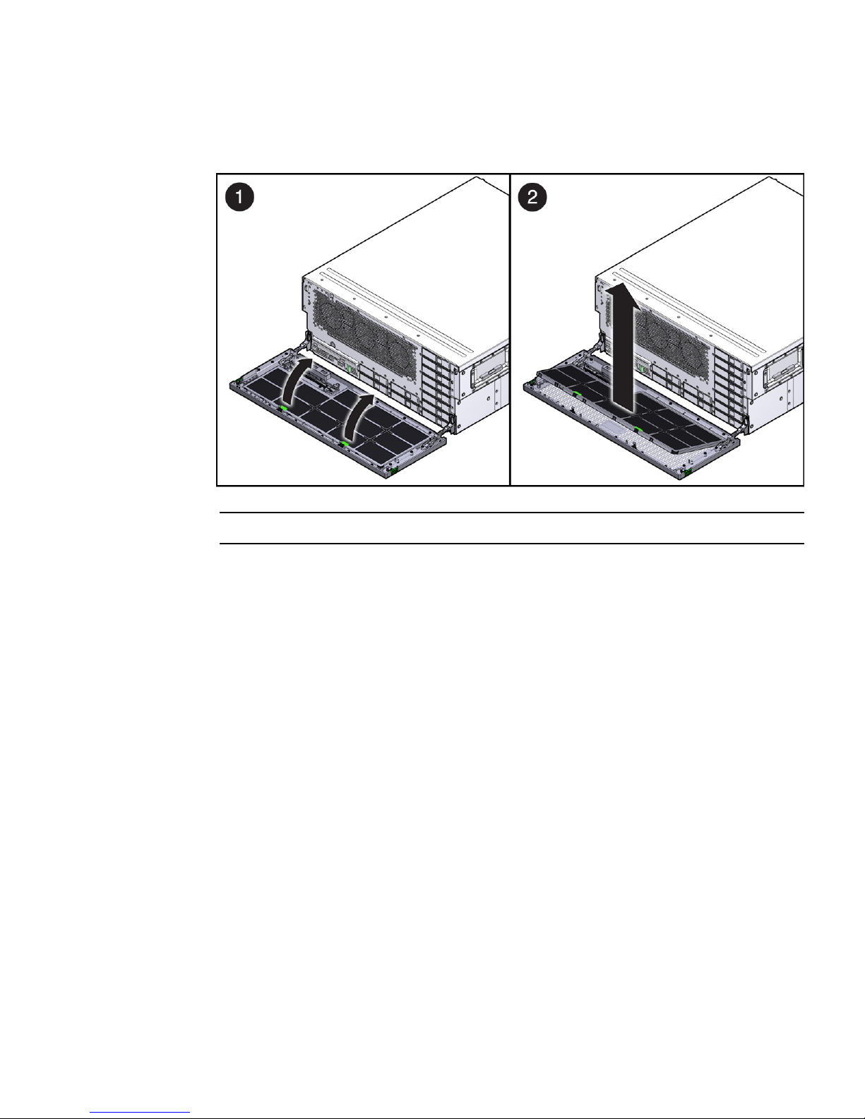
FIGURE 3-2 Removing the Air Filter
Note – Do not operate the server without an air filter.
▼ Install the Air Filter
1. Remove the replacement air filter from its packaging.
2. Insert the air filter into the bezel (
FIGURE 3-3).
Chapter 3 Replacing Components 3-3

FIGURE 3-3 Installing the Air Filter
3. Close the bezel.
3.2 Replacing a Power Supply
The server’s redundant hot-swappable power supplies enable you to remove and
replace one or two power supplies without shutting the server down, provided that
the other power supplies are online and working.
If a power supply fails and you do not have a replacement available, leave the failed
power supply installed to ensure proper air flow in the server.
3-4 Sun Netra X4450 Server Service Manual • August 2008
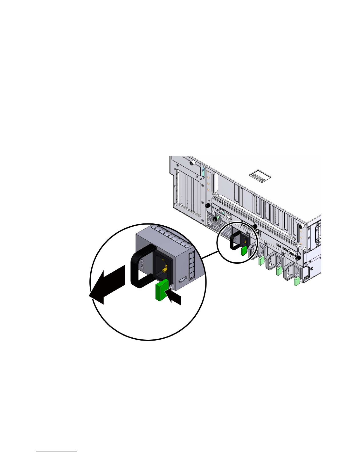
▼ Remove a Power Supply
1. Identify which power supply requires replacement.
A lighted amber indicator on a power supply indicates that a failure was
detected.
2. Disconnect the power cord from the faulty power supply.
3. Grasp the power supply handle, and push the power supply latch to the right
(
FIGURE 3-4).
FIGURE 3-4 Removing the Power Supply
4. Pull the power supply out of the chassis.
Chapter 3 Replacing Components 3-5
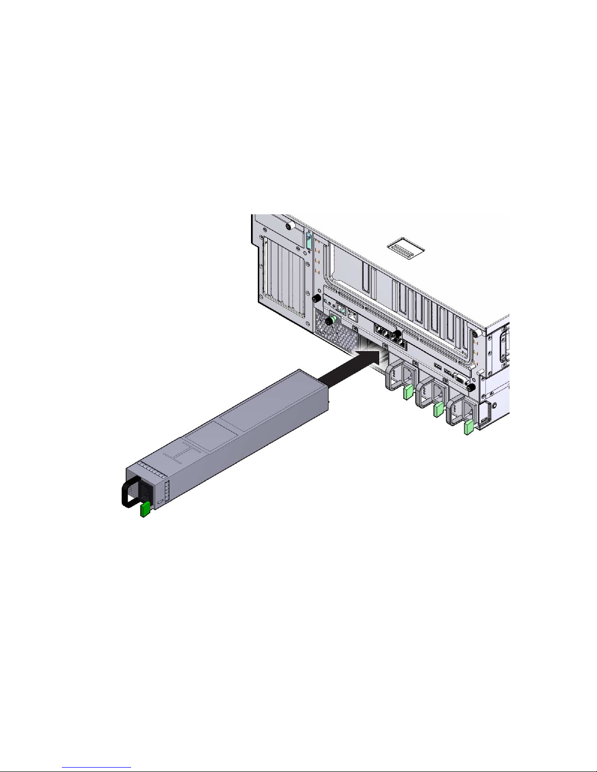
▼ Install a Power Supply
1. Remove the replacement power supply from its packaging, and place the
power supply on an antistatic mat.
2. Slide the power supply into bay until it is fully seated (
FIGURE 3-5 Installing a Power Supply
FIGURE 3-5).
3. Reconnect the power cord to the power supply.
4. Verify that the amber indicator on the replaced power supply and that the
Service Required Indicators are not lit.
3-6 Sun Netra X4450 Server Service Manual • August 2008

3.3 Replacing a Hard Drive
The hard drives in the server are hot-pluggable, but this capability depends on how
the hard drives are configured. To hot-plug a drive, you must be able to take the
drive offline by preventing any applications from accessing the drive and removing
the logical software links to the drive.
The following situations inhibit the ability to perform hot-plugging of a drive:
■ The hard drive provides the operating system, and the operating system is not
mirrored on another drive.
■ The hard drive cannot be logically isolated from the online operations of the
server.
If your drive falls into one of these conditions, you must shut the system down
before you replace the hard drive.
Note – Replacing a hard drive does not require removing the server from a rack.
▼ Remove a Hard Drive
If the drive you want to remove cannot be hot-plugged, perform the tasks in Chapter
2 before you perform the steps in this procedure.
1. Open the bezel (
FIGURE 3-6).
Caution – Do not open the bezel on a flat surface. The front of the server must be
hanging over the edge of a flat surface to avoid damaging the bezel hinges.
Chapter 3 Replacing Components 3-7

FIGURE 3-6 Opening the Bezel
2. Type the Solaris OS commands required to stop using the hard drive.
Exact commands required depend on the configuration of your hard drives. You
might need to unmount file systems or perform RAID commands.
3. On the drive you plan to remove, push the latch release button (
FIGURE 3-7).
3-8 Sun Netra X4450 Server Service Manual • August 2008
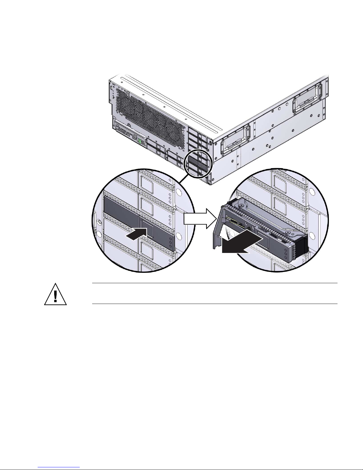
FIGURE 3-7 Removing a Hard Drive
Caution – The latch is not an ejector. Do not bend it too far to the left. Doing so can
damage the latch.
4. Grasp the latch, and pull the drive out of the drive slot.
Chapter 3 Replacing Components 3-9

▼ Install a Hard Drive
1. Remove the replacement hard drive from its packaging, and place it on an
antistatic mat.
2. Align the replacement drive to the drive slot.
The hard drive is physically addressed according to the slot in which it is
installed. It is important to install a replacement drive in the same slot as the
drive that was removed.
3. Slide the drive into the bay until it is fully seated (
FIGURE 3-8 Installing a Hard Drive
FIGURE 3-8).
4. Close the latch to lock the drive in place.
3-10 Sun Netra X4450 Server Service Manual • August 2008
5. Close the bezel.
6. Perform administrative tasks to reconfigure the hard drive.
The procedures that you perform at this point depend on how your data is
configured. You might need to partition the drive, create file systems, load data
from backups, or have it updated from a RAID configuration.
3.4 Replacing the Optical Media Drive
The optical media drive in the server is not hot-pluggable. You cannot remove it
while the system is running.
▼ Remove the Optical Media Drive
1. Prepare the server for optical media drive removal.
See Chapter 2.
2. Open the bezel.
Caution – Do not open the bezel on a flat surface. The front of the server must be
hanging over the edge of a flat surface to avoid damaging the bezel hinges.
3. Push the release tab to the left, and pull the probe forward, freeing the optical
media drive (
FIGURE 3-9).
Chapter 3 Replacing Components 3-11
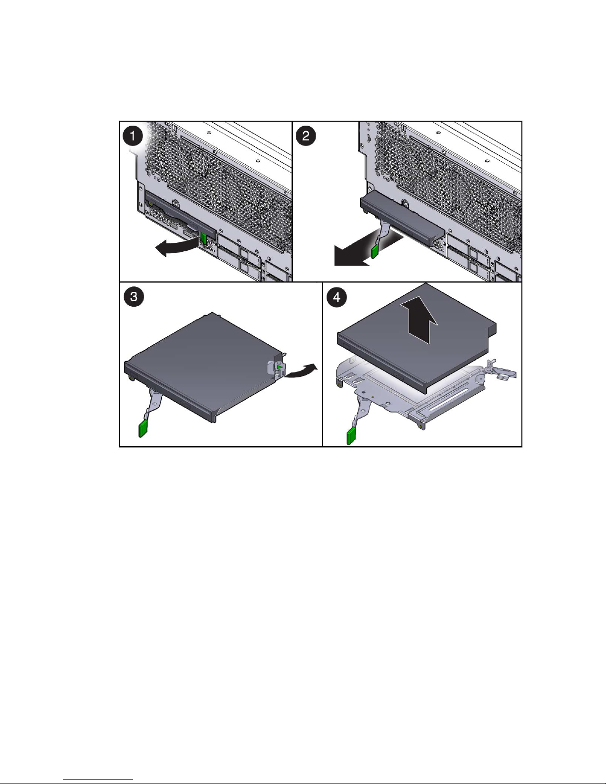
FIGURE 3-9 Releasing the Optical Media Drive
4. Remove the optical media drive from server, and set it aside on an antistatic
mat.
▼ Install the Optical Media Drive
1. Remove the replacement optical media drive from its packaging, and place it
on an antistatic mat.
2. Hold the tab to the left, and insert the optical media drive into the chassis
(
FIGURE 3-10).
3-12 Sun Netra X4450 Server Service Manual • August 2008
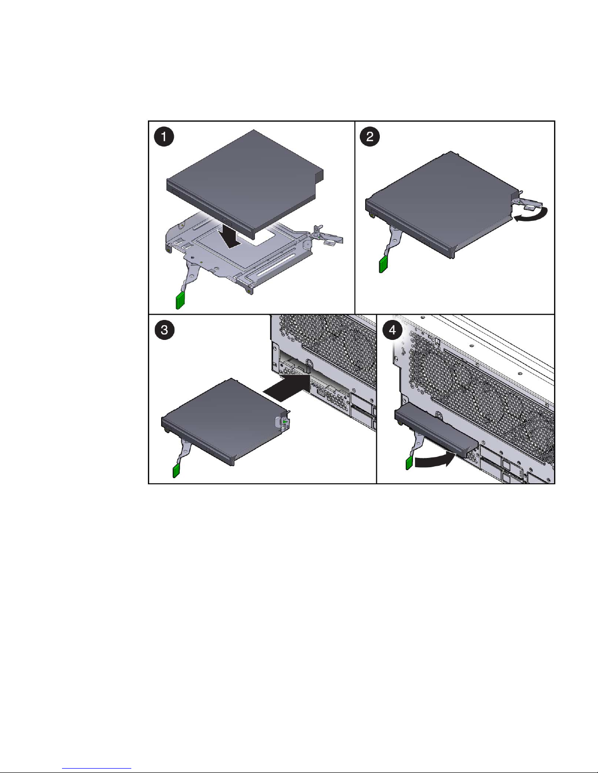
FIGURE 3-10 Inserting the Optical Media Drive
3. Press the optical media drive in until it seats, and release the tab.
4. Close the bezel.
5. Consider your next step:
■ If you installed the optical media drive as part of another procedure, return to
that procedure.
■ Otherwise, perform the tasks needed to bring the server back online.
See Chapter 4.
Chapter 3 Replacing Components 3-13

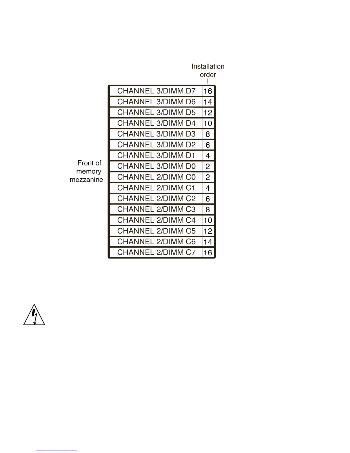
3.5 Replacing FB-DIMMs
Use the FB-DIMM configuration rules to help you plan the memory configuration of
your server. There are 32 slots that hold industry-standard FB-DIMM memory
modules. General rules are:
■ FB-DIMMs must be installed in identical pairs (that is, the same size, speed, and
organization).
■ A replacement FB-DIMM must have the same part number as the other FB-DIMM
in its pair. If you are unable to obtain a matching FB-DIMM, you must replace
both FB-DIMMs in the pair.
■ FB-DIMM pairs must be installed in the following slot order: A0/B0, C0/D0,
A1/B1, then C1/D1.
■ FB-DIMM capacities can be different between slots. For example, you can install a
pair of 2-GB FB-DIMMs in slots A0 or B0 and a pair of 1-GB FB-DIMMs in slots
C0 or D0.
■ Highest capacity FB-DIMMs must be installed in the lowest numbered slots. For
instance, if you have four 4-GB FB-DIMMs and four 2-GB FB-DIMMs, you must
install the 4-GB FB-DIMMs in slots A0/B0 and C0/D0, and you must install the
2-GB FB-DIMMs in slots A1/B1 and C1/D1.
Caution – Ensure that all power is removed from the server before removing or
installing FB-DIMMs. You must disconnect the power cables before performing this
procedure.
3-14 Sun Netra X4450 Server Service Manual • August 2008

FIGURE 3-11 FB-DIMM Layout for Branch 0
FIGURE 3-12 FB-DIMM Layout for Branch 1
Chapter 3 Replacing Components 3-15
Note – FB-DIMM names in ILOM messages are displayed with the full FRU name,
such as /SYS/MB/CMP0/BR0/CH0/D0.
Caution – Always perform antistatic measures by using a wrist strap and an
antistatic mat for handling and storing removable components.
3-16 Sun Netra X4450 Server Service Manual • August 2008

▼ Locate a Faulty FB-DIMM
The system Service Required Indicator lights if the system detects a FB-DIMM fault.
See Section 1.2.1 “Memory Fault Handling” on page 1-4.
1. Prepare the server for FB-DIMM removal.
See Chapter 2.
2. Press the FB-DIMM fault locator button.
The button is located on the left edge of the memory mezzanine.
3. Note the location of faulty FB-DIMMs.
Faulty FB-DIMMs are identified with a corresponding amber indicator.
Note – The FB-DIMM fault indicator remains lit only for a few minutes.
4. Ensure that all FB-DIMMs are seated correctly in their slots.
▼ Remove FB-DIMMs
1. If you have not already done so, prepare the server for FB-DIMM removal.
See Chapter 2.
2. Push down on the ejector tabs on each side of the FB-DIMM until the
FB-DIMM is released (
FIGURE 3-13).
Chapter 3 Replacing Components 3-17

FIGURE 3-13 Removing FB-DIMMs
3. Grasp the top corners of the faulty FB-DIMM, and remove it from the memory
mezzanine.
4. Place the FB-DIMM on an antistatic mat.
5. Repeat Step 2 through Step 4 to remove any additional FB-DIMMs.
▼ Install FB-DIMMs
Caution – Ensure that all power is removed from the server before removing or
installing FB-DIMMs or damage to the FB-DIMMs might occur. You must disconnect
the power cables from the system before performing this procedure.
1. If you are adding memory, prepare the server for service.
See Chapter 2.
2. Unpackage the FB-DIMMs, and place them on an antistatic mat.
3. Ensure that the ejector tabs are in the open position.
4. Line up the replacement FB-DIMM with the connector (
Align the FB-DIMM notch with the key in the connector. This ensures that the
FB-DIMM is oriented correctly.
FIGURE 3-14).
3-18 Sun Netra X4450 Server Service Manual • August 2008
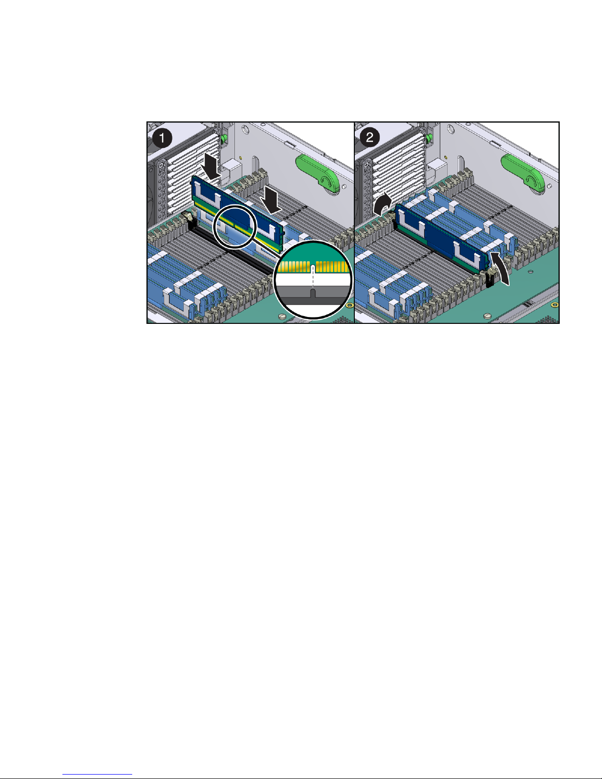
FIGURE 3-14 Inserting an FB-DIMM Into a Slot
5. Push the FB-DIMM into the connector until the ejector tabs lock the FB-DIMM
in place.
If the FB-DIMM does not easily seat into the connector, verify that the orientation
of the FB-DIMM is as shown in
FIGURE 3-14. If the orientation is reversed, damage
to the FB-DIMM might occur.
6. Repeat Step 3 through Step 5 until all replacement FB-DIMMs are installed.
7. Consider your next step:
■ If you installed FB-DIMMs as part of another procedure, return to that
procedure.
■ If you are only installing FB-DIMMs, see Chapter 4 for the tasks needed to
bring the server back online.
Chapter 3 Replacing Components 3-19

3.6 Replacing System Fan 0
System fan 0 is labeled FT0 and is located at the front of the chassis.
▼ Remove System Fan 0
1. Prepare the server for fan assembly removal.
See Chapter 2.
2. Insert your forefinger and thumb into the holes at the top of the fan assembly,
squeeze them together, and lift the fan assembly from the chassis (
FIGURE 3-15 Lifting System Fan 0 From the Chassis
FIGURE 3-15).
3. Set the fan assembly on an antistatic mat.
4. Consider your next step:
■ If you removed the fan assembly as part of another procedure, return to that
procedure.
■ Otherwise, continue to “Install System Fan 0” on page 3-21.
▼ Install System Fan 0
1. Remove the replacement fan assembly from its packaging, and place it on an
antistatic mat.
3-20 Sun Netra X4450 Server Service Manual • August 2008

2. Insert your forefinger and thumb into the holes at the top of the fan assembly,
squeeze them together, and lower the fan assembly into the chassis
(
FIGURE 3-16).
FIGURE 3-16 Installing System Fan 0 Into the Chassis
3. Consider your next step:
■ If you installed the fan assembly as part of another procedure, return to that
procedure.
■ Otherwise, see Chapter 4 to perform the tasks needed to bring the server back
online.
Chapter 3 Replacing Components 3-21

3.7 Replacing System Fan 1
System fan 1 is labeled FT1 and is located directly behind the hard drive stack.
▼ Remove System Fan 1
1. Prepare the server for fan removal.
See Chapter 2.
2. Slide the bracket forward, and lift the fan assembly out (
FIGURE 3-17 Lifting Out System Fan 1
FIGURE 3-17).
3. Set the fan aside on an antistatic mat.
4. Continue to “Install System Fan 1” on page 3-23.
3-22 Sun Netra X4450 Server Service Manual • August 2008

▼ Install System Fan 1
1. Remove the replacement fan assembly from its packaging, and place it on an
antistatic mat.
2. Lower the fan assembly into the chassis, and press it down until the brackets
seat properly (
FIGURE 3-18 Installing System Fan 1
FIGURE 3-18).
3. See Chapter 4 to perform the tasks needed to bring the server back online.
3.8 Replacing System Fan 2
System fan 2 is labeled FT2 and is located at the rear of the chassis.
Chapter 3 Replacing Components 3-23
▼ Remove System Fan 2
1. Prepare the server for fan removal.
See Chapter 2
2. Untighten the captive screw on the fan assembly housing, and pull the
housing out of the chassis (
FIGURE 3-19 System Fan 2 Removal
FIGURE 3-18).
3. Set the fan assembly on an antistatic mat.
4. Continue to “Replacing System Fan 1” on page 3-22.
▼ Install System Fan 2
1. Remove the replacement fan assembly from its packaging, and place it on an
antistatic mat.
2. Slide the fan assembly housing into the chassis until it is fully seated.
3. Tighten the captive screw on the housing.
4. See Chapter 4 to perform the tasks needed to bring the server back online.
3-24 Sun Netra X4450 Server Service Manual • August 2008

3.9 Replacing PCI Cards
The PCI mezzanine secures the PCI cards into place with green PCI card retainers
and captive (nonremovable) securing screws.
3.9.1 Replace PCI-X and PCIe Cards in Slots 0-3
Note – The maximum power of any one PCI card is 25 watts. Only slots 0-3 accept
long cards.
▼ Remove PCI-X and PCIe Cards in Slots 0-3
1. Prepare the server for PCI card removal.
See Chapter 2.
2. Remove the PCI air baffle (
FIGURE 3-21).
Chapter 3 Replacing Components 3-25

FIGURE 3-20 Removing a PCI Card From Slots 0-3
3. Rotate the securing bracket up.
4. Lift the card out of the slot.
Set the card on an antistatic mat.
5. Consider your next step:
■ If you are replacing the card, continue to “Install PCI-X and PCIe Cards in
Slot 0-3” on page 3-27.
■ If you do not replace the card, install a filler panel.
6. Rotate the securing bracket down.
7. See Chapter 4 to perform the tasks needed to bring the server back online.
3-26 Sun Netra X4450 Server Service Manual • August 2008

▼ Install PCI-X and PCIe Cards in Slot 0-3
1. Prepare the server for PCI card installation.
See Chapter 2.
2. Remove the replacement card from its packaging and place it onto an antistatic
mat.
3. Remove the PCI air baffle (
FIGURE 3-21 PCI Slot Securing Bracket
FIGURE 3-21).
4. Swing the PCI securing bracket up.
5. If a filler panel is installed, remove it by pulling the tab.
6. Lower the card into the PCI slot.
7. Rotate the PCI securing bracket down.
8. Replace the PCI air baffle.
9. See Chapter 4 to perform the tasks needed to bring the server back online.
Chapter 3 Replacing Components 3-27

3.9.2 Replacing PCI Cards in the PCI Mezzanine
Note – In a fully loaded system, the maximum power of any one PCI card is 25
watts.
▼ Remove PCI Cards in the PCI Mezzanine
1. Prepare the server for PCI card removal.
See Chapter 2.
2. With the PCI mezzanine installed and cabled, identify which card is to be
removed.
3. Loosen the appropriate PCI card retainer (
FIGURE 3-22).
3-28 Sun Netra X4450 Server Service Manual • August 2008
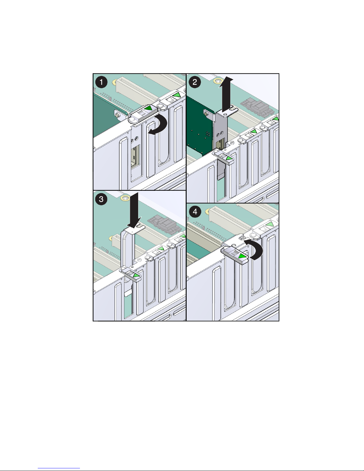
FIGURE 3-22 Removing a PCI Card From the PCI Mezzanine
4. Slide the card to the left and lift it out of the PCI mezzanine.
Set the card aside on an antistatic mat.
5. Consider your next step:
■ If you are replacing the card, continue to “Install PCI Cards in the PCI
Mezzanine” on page 30.
■ If you do not replace the card, install a filler panel.
6. See Chapter 4 to perform the tasks needed to bring the server back online.
Chapter 3 Replacing Components 3-29

▼ Install PCI Cards in the PCI Mezzanine
1. Prepare the server for PCI card installation.
See Chapter 2.
2. Remove the replacement card from its packaging and place it onto an antistatic
mat.
3. If a filler panel is installed, remove it by pulling the tab.
4. Lower the card into position on the PCI mezzanine, then slide it to the right to
seat it into the connector.
5. Tighten the PCI retainer.
6. See Chapter 4 to perform the tasks needed to bring the server back online.
3.10 Replacing the System/Alarm LED Board
To replace the system/alarm LED board, you must remove the following
components:
■ Air baffle (see “Remove the Air Baffle” on page 2-6)
■ Memory mezzanine (see “Remove the Memory Mezzanine” on page 2-6
■ System fan 0 (see “Replacing System Fan 0” on page 3-20)
▼ Remove the System/Alarm LED Board
1. Prepare the server for system/alarm LED board removal.
See Chapter 2.
2. Remove system fan 0 assembly.
See “Replacing System Fan 0” on page 3-20.
3. Loosen the thumbscrew of the LED board, and swing the board out to the left
(
FIGURE 3-23).
3-30 Sun Netra X4450 Server Service Manual • August 2008

FIGURE 3-23 Removing the LED Board
4. Carefully lift the LED board.
5. Set the LED board aside on an antistatic mat.
6. Continue to “Install the System/Alarm LED Board” on page 3-31.
▼ Install the System/Alarm LED Board
1. Remove the replacement LED board from its packaging and place it on an
antistatic mat.
2. Insert the tab on the LED board into the slot on the chassis.
3. Swing the LED board right to the chassis and tighten the thumbscrew.
4. Install system fan 0.
See “Replacing System Fan 0” on page 3-20.
5. See Chapter 4 to perform the tasks needed to bring the server back online.
Chapter 3 Replacing Components 3-31

3.11 Replacing the SAS Expander Card
Use the instructions in this section to replace the SAS expander card.
▼ Remove the SAS Expander Card
1. Prepare the server for removal of the SAS expander card.
See Chapter 2.
2. Remove system fan 1.
See Section 3.7 “Replacing System Fan 1” on page 3-22.
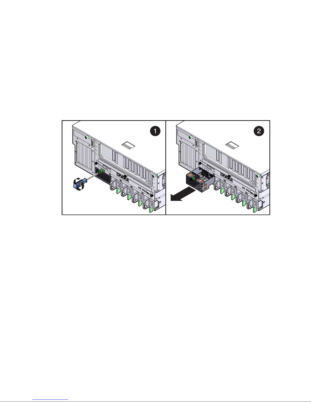
3. Disconnect the two cables attached to the expander card.
4. Loosen the green captive screw on the expander card (
FIGURE 3-24).
3-32 Sun Netra X4450 Server Service Manual • August 2008

FIGURE 3-24 Removing the SAS Expander Card
5. Slide the expander card straight back until the keyhole slots on the front of the
card clear the expansion card posts.
6. Pull the expander card away from the chassis wall until it is clear of the
expander posts.
▼ Install the SAS Expander Card
1. Remove the new SAS expander card from its packaging.
2. Align the keyhole slots on the expander card with the posts on the chassis
wall.
Chapter 3 Replacing Components 3-33

FIGURE 3-25 Installing the SAS Expander Card
3. Push the expander card against the chassis wall, then push the card forward
until the card is seated into the interconnect slot.
4. Tighten the green captive screw, and attach the two expansion cables.
5. Attach the two expansion cables.
6. See Chapter 4 for instructions on how to return the server to service.
3-34 Sun Netra X4450 Server Service Manual • August 2008

3.12 Replacing the Battery
Before you replace the battery, you must remove the following components as part
of preparing the server for battery removal:
■ Air baffle (see “Remove the Air Baffle” on page 2-6)
■ PCI mezzanine (see “Remove the PCI Mezzanine” on page 2-7)
▼ Remove the Battery
1. Prepare the server for battery removal.
See Chapter 2.
2. Pry the battery out of the motherboard (
FIGURE 3-26 Prying the Battery From the Motherboard
FIGURE 3-26).
3. Set the battery aside on an antistatic mat.
Chapter 3 Replacing Components 3-35

▼ Install the Battery
Note – The battery is a CR-1225 or equivalent.
1. Remove the replacement battery from its packaging.
2. Press the new battery in with the “+” side facing up (
FIGURE 3-27 Inserting the Battery Into the Service Processor Board
FIGURE 3-27).
3. See Chapter 4 to perform the tasks needed to bring the server back online.
3-36 Sun Netra X4450 Server Service Manual • August 2008

3.13 Replacing the Motherboard Assembly
Use the instructions in this section to replace the motherboard assembly.
▼ Remove the Motherboard Assembly
Before you can remove the motherboard, you must remove the following
components:
■ Air baffle (see “Remove the Air Baffle” on page 2-6)
■ Memory mezzanine (see “Remove the Memory Mezzanine” on page 2-6
■ PCI mezzanine (see “Remove the PCI Mezzanine” on page 2-7)
■ System fan 0 (see “Replacing System Fan 0” on page 3-20)
1. Prepare the server for motherboard assembly removal.
See Chapter 2.
2. Disconnect the cable connected to the motherboard (
FIGURE 3-28).
Chapter 3 Replacing Components 3-37

FIGURE 3-28 Removing the Cable Connected to the Motherboard
3. Loosen or remove the screws that secure the motherboard assembly to the
chassis (
3-38 Sun Netra X4450 Server Service Manual • August 2008
FIGURE 3-29).

FIGURE 3-29 Removing the Motherboard Assembly Screws
4. Loosen the two captive screws at the center of the motherboard assembly
(
FIGURE 3-29).
5. Lift slighty and slide the motherboard assembly forward approximately one
inch (25.4 mm) (
6. Lift up on the right edge to approximately a 45 degree angle (
7. Remove the motherboard assembly from the chassis (
FIGURE 3-30).
FIGURE 3-30).
FIGURE 3-30).
Chapter 3 Replacing Components 3-39
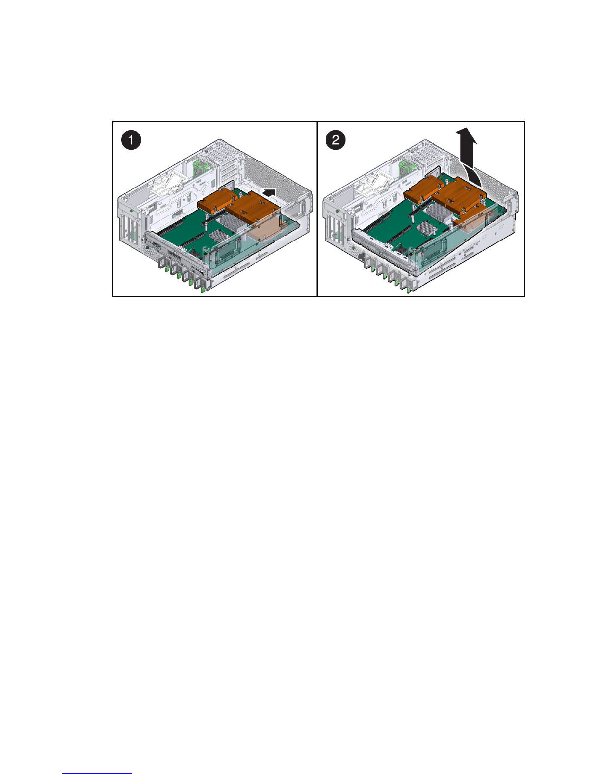
FIGURE 3-30 Removing the Motherboard Assembly From the Chassis
8. Set the motherboard assembly aside on an antistatic mat.
▼ Install the Motherboard Assembly
1. Remove the replacement motherboard assembly from its packaging, and place
it on an antistatic mat.
2. Lower the left edge of the motherboard assembly into the chassis, then the
entire board, and while slightly elevated, slide the motherboard assembly to
the back of the chassis (
FIGURE 3-31).
3-40 Sun Netra X4450 Server Service Manual • August 2008

FIGURE 3-31 Installing the Motherboard Assembly Into the Chassis
3. Align the motherboard assembly screw holes over the chassis standoffs.
4. Tighten the captive screws at the center of the motherboard assembly
(
FIGURE 3-32).
Chapter 3 Replacing Components 3-41

FIGURE 3-32 Installing the Motherboard Assembly Screws
5. Install the two power screws and four other screws that secure the
motherboard assembly to the chassis (
FIGURE 3-32).
6. Reconnect the cable to the connector on the motherboard assembly
(
FIGURE 3-33):
3-42 Sun Netra X4450 Server Service Manual • August 2008

FIGURE 3-33 Reconnecting the Cable to the Motherboard Assembly
7. Replace system fan 0 (see “Replacing System Fan 0” on page 3-20).
8. See Chapter 4 to perform the tasks needed to bring the server back online.
3.14 Replacing the Power Board
To remove the power board, you must remove the following components as part of
preparing the server for power board replacement:
■ Memory mezzanine (see “Remove the Memory Mezzanine” on page 2-6)
■ PCI mezzanine (see “Remove the PCI Mezzanine” on page 2-7)
■ System fan 0 (see “Replacing System Fan 0” on page 3-20)
Chapter 3 Replacing Components 3-43

■ Optical media drive (see “Replacing the Optical Media Drive” on page 3-11)
■ Motherboard (see “Remove the Motherboard Assembly” on page 3-37)
▼ Remove the Power Board
1. Prepare the server for power board removal.
See Chapter 2.
2. Perform the removal instructions in the following sections:
■ “Remove System Fan 0” on page 3-20
■ “Remove the Optical Media Drive” on page 3-11
■ “Remove the Motherboard Assembly” on page 3-37
3. Remove the screws that secure the power board to the chassis (
FIGURE 3-34).
3-44 Sun Netra X4450 Server Service Manual • August 2008

FIGURE 3-34 Removing the Power Board Screws
4. Lift the power board out of the chassis, and set it aside on an antistatic mat.
5. Continue to “Install the Power Board” on page 3-46.
Chapter 3 Replacing Components 3-45

▼ Install the Power Board
1. Remove the replacement power board from its packaging and place it on an
antistatic mat.
2. Lower the power board into the chassis, aligning the board’s holes with the
standoffs in the chassis.
3. Install the screws firmly to secure the power board to the chassis.
4. Perform the installation instructions in the following sections:
■ “Install the Motherboard Assembly” on page 3-40
■ “Replacing System Fan 0” on page 3-20
■ “Install the Optical Media Drive” on page 3-12
5. See Chapter 4 to perform the tasks needed to bring the server back online.
3-46 Sun Netra X4450 Server Service Manual • August 2008

CHAPTER
4
Returning the Server to Service
This chapter contains the tasks to perform after replacing components within the
server.
4.1 Returning the Server to Service
After replacing components inside of the server, perform the following tasks:
■ “Install the PCI Mezzanine” on page 4-1
■ “Install the Air Baffle” on page 4-4
■ “Install the Top Cover” on page 4-4
■ “Reinstall the Server in the Rack” on page 4-5
■ “Reconnect the Cables to the Server” on page 4-5
■ “Power On the Server” on page 4-6
When replacing some of the components, not all of these tasks are necessary. The
replacement procedures for those components address this fact.
▼ Install the PCI Mezzanine
If you removed the PCI mezzanine to service another component, use the
instructions in this section to install the PCI mezzanine.
1. Ensure that all three of the PCI riser cards are fully seated in the motherboard.
2. Align the mezzanine with the chassis, and lower it gently into the chassis.
Do not force the mezzanine down. Use the securing levers to seat the mezzanine
fully into the chassis.
4-1

FIGURE 4-1 Installing the PCI Mezzanine
3. Push the securing levers down to seat the mezzanine into the chassis.
4. Connect the three system cables to the mezzanine board.
4-2 Sun Netra X4450 Server Service Manual • August 2008

▼ Install the Memory Mezzanine
If you removed the memory mezzanine to service another component, use the
instructions in this section to install the memory mezzanine.
1. Ensure that both of the memory mezzanine riser cards are fully seated in the
motherboard.
2. Align the mezzanine with the chassis, and gently lower it into the chassis.
Do not force the mezzanine into the chassis. Use the securing levers to seat the
mezzanine fully into the chassis.
FIGURE 4-2 Installing the Memory Mezzanine
3. Push the securing levers down to seat the memory mezzanine into the chassis.
Chapter 4 Returning the Server to Service 4-3

▼ Install the Air Baffle
If you removed the air baffle to service other components, use the instructions in this
section to install the air baffle.
1. Align the baffle hinges with the holes in the chassis.
FIGURE 4-3 Installing the Air Baffle
2. Insert one hinge to one of the holes, and gently squeeze the other side of the
air baffle until you can insert the other hinge.
▼ Install the Top Cover
1. Place the top cover on the chassis.
Set the cover down so that it hangs over the rear of the server by about an inch
(25 mm).
2. Slide the cover forward until it latches into place (
4-4 Sun Netra X4450 Server Service Manual • August 2008
FIGURE 4-4).

FIGURE 4-4 Installing Top Cover
3. Tighten the captive screws on the rear of the cover.
▼ Reinstall the Server in the Rack
The steps you must complete to return the server to the rack depend on the type of
rack and the mounting kit.
● Refer to the Sun Netra X4450 Server Installation Guide for instructions on how
to install the server into the rack.
You can use the instructions in the Sun Netra X4450 Server Installation Guide to
finish the installation process, or you can return to this section to finish the
process.
▼ Reconnect the Cables to the Server
1. Reconnect the Ethernet and PCI cables as appropriate.
2. If necessary, reinstall the appropriate cables into the CMA.
3. Reconnect the power cables.
Chapter 4 Returning the Server to Service 4-5

▼ Power On the Server
As soon as the power cords are connected, standby power is applied. Depending on
the configuration of the firmware, the system might boot. If not, follow this
procedure.
● If the server does not boot, do one of the following:
■ Use the tip of a pen to press the power button on the bezel.
■ Type the poweron command to the system console.
For example:
sc> poweron
4-6 Sun Netra X4450 Server Service Manual • August 2008

APPENDIX
A
Configuring BIOS and POST
This chapter describes how to view or modify the BIOS Setup Utility screens in the
Sun Netra X4450. The BIOS Setup utility reports system information and can be used
to configure the server BIOS settings.
The Basic Input/Output System (BIOS) has a Setup utility stored in the BIOS flash
memory. The configured data is provided with context-sensitive help and is stored
in the system's battery-backed CMOS RAM. If the configuration stored in the CMOS
RAM is invalid, the BIOS settings default to the original state specified at the factory.
The following topics are included:
■ Section A.1 “Using BIOS Menu Items” on page A-7
■ Section A.2 “BIOS Considerations” on page A-8
■ Section A.3 “BIOS Setup Screens” on page A-11
■ Section A.4 “Viewing Event Logs” on page A-31
■ Section A.5 “Power-On Self-Test (POST)” on page A-31
A.1 Using BIOS Menu Items
You can access BIOS configuration screens from the following interfaces:
■ Use a USB keyboard, mouse, and VGA monitor connected directly to the server.
■ Use a terminal (or terminal emulator connected to a computer) through the serial
port on the back panel of the server.
A-7

Access BIOS Configuration Screens and Change
the System’s Parameters
1. Enter the BIOS Setup utility by pressing the F2 key while the system is
performing the power-on self-test (POST).
When BIOS is started, the main BIOS Setup menu screen is displayed.
2. Highlight the field to be modified using the arrow and Tab keys.
Use the left and right arrow keys to move sequentially back and forth through
the menu screens. Fields that can be reconfigured are displayed in color. All
other fields are nonconfigurable.
■ Use the Up and Down keys on the keyboard, to scroll through a menu.
■ Use the Tab key to move back and forth across columns.
3. Press Enter to select the field.
A dialog box shows the available options.
4. Modify the Setup field and close the screen.
5. If you need to modify other setup parameters, use the arrow and Tab keys to
navigate to the desired screen and menu item, and then repeat Step 1 through
Step 4.
Otherwise, go to Step 6.
6. Press and release the right arrow key until the Exit menu screen appears.
7. Follow the instructions on the Exit menu screen to save your changes and exit
the Setup utility.
A.2 BIOS Considerations
This section contains information and considerations regarding the system BIOS.
A.2.1 Peripheral Component Interconnect (PCI) Card
Slot Booting Priority
For the locations of the Sun Netra X4450 server PCI slots, see Section 3.9 “Replacing
PCI Cards” on page 3-25.
A-8 Sun Netra X4450 Server Service Manual • August 2008

The slots for the PCI cards are detected by the BIOS during startup in the following
order:
1. PCI-X slot 0
2. PCI-X slot 1
3. PCIe slot 2
4. PCIe slot 3
5. PCIe slot 4
6. PCIe slot 5
7. PCIe slot 6
8. PCIe slot 7
9. PCIe slot 8
10. PCIe slot 9
A.2.2 Ethernet Port (NIC) Device and Driver Naming
The Sun Netra X4450 server has four 10/100/1000BASE-T Gigabit Ethernet ports
(NICs). The chassis labeling of the physical ports is shown in
FIGURE A-1 Ethernet Ports
FIGURE A-1.
Note – The device naming for the NICs is reported differently by different
interfaces and operating systems.
Appendix A Configuring BIOS and POST A-9

A.2.3 NIC Naming
TABLE A-1 illustrates the default naming used by the various operating systems for
the four NICs shown in
TABLE A-1 Sun Netra X4450 NIC Naming
BIOS slot 108 slot 108 slot 108 slot 108
Solaris 10 nge0 nge1 e1000g0 e1000g1
Red Hat Linux eth2 eth3 eth0 eth1
SUSE Linux eth0 eth1 eth2 eth3
Windows 2003 net net2 net3 net4
A.2.3.1 Sun Netra X4450 Server NIC Booting Priority
The order in which the BIOS detects the Ethernet ports during bootup, and the
corresponding drivers that control those ports are listed below:
1. NET 0 (Nvidia NGE 0)
FIGURE A-1.
Net 0 Net 1 Net 2 Net3
2. NET 1 (Nvidia NGE 1)
3. NET 2 (Intel E1000 G0)
4. NET 3 (Intel E1000 G1)
A-10 Sun Netra X4450 Server Service Manual • August 2008

A.3 BIOS Setup Screens
TABLE A-2 contains summary descriptions of the top-level BIOS setup screens.
TABLE A-2 BIOS Setup Screens Summary
Screen Description Section
Main General product information, including BIOS
type, processor, memory, and time and date.
Advanced Configuration information for the CPU,
memory, IDE, Super IO, trusted computing,
USB, PCI, MPS, and other information.
Boot Configure the boot device priority (hard
drives and the optical media drive).
Server Server devices can be configured by the
BIOS (if applicable).
Security Set or change the user and supervisor
passwords.
Exit Save changes and exit, discard changes and
exit, discard changes, or load optimal or failsafe defaults.
FIGURE A-2 summarizes the BIOS menu tree. See Section A.3.1 “BIOS Setup Menu
Section A.3.1.1 “BIOS Main
Menu Screens” on page A-13
Section A.3.1.2 “BIOS
Advanced Menu Screens” on
page A-14
Section A.3.1.3 “BIOS Boot
Menu Screens” on page A-20
Section A.3.1.4 “BIOS Server
Menu Screens” on page A-23
Section A.3.1.5 “BIOS Security
Menu Screens” on page A-27
Section A.3.1.6 “BIOS Exit
Menu Screens” on page A-27
Screens” on page A-12 for examples of each of these screens.
Appendix A Configuring BIOS and POST A-11

FIGURE A-2 BIOS Utility Menu Tree
Main
Product
Information
Advanced
CPU
Settings
System Memory Settings
IDE
Configuration
Super
IO
Trusted
Computing
USB
Configuration
PCI
Configuration
Boot
Boot
Settings
Boot Device
Priority
Hard Disk
Drives
CD/DVD
Drives
USB
Configuration
Server
LAN
Configuration
Remote
Access
View Event
Log
Reset SP (BMC)
Event Log
Security
Exit
MPS
Configuration
A.3.1 BIOS Setup Menu Screens
The following figures show sample Sun Netra X4450 BIOS Setup Utility screens.
Note – The screens shown are examples. The version numbers and the screen items
and selections shown are subject to change over the life of the product.
All settings are set to the optimal default at startup.
A-12 Sun Netra X4450 Server Service Manual • August 2008

A.3.1.1 BIOS Main Menu Screens
The BIOS Main screens provide general product information, including BIOS type,
processor type, memory, and time and date. The Sun Netra X4450 has the following
BIOS Main screens.
FIGURE A-3 BIOS Setup Utility: Main - System Overview
Appendix A Configuring BIOS and POST A-13

FIGURE A-4 BIOS Setup Utility: Main - Product Information
A.3.1.2 BIOS Advanced Menu Screens
The BIOS Advanced screens provide detailed configuration information for the CPU,
memory, IDE, Super IO, trusted computing, USB, PCI, MPS, and other system
information.
The Sun Netra X4450 has the following BIOS Advanced screens:
A-14 Sun Netra X4450 Server Service Manual • August 2008

FIGURE A-5 BIOS Setup Utility: Advanced
Appendix A Configuring BIOS and POST A-15

FIGURE A-6 BIOS Setup Utility: Advanced - CPU Settings
FIGURE A-7 BIOS Setup Utility: Advanced - System Memory Settings
A-16 Sun Netra X4450 Server Service Manual • August 2008

FIGURE A-8 BIOS Setup Utility: Advanced - IDE Configuration
FIGURE A-9 BIOS Setup Utility: Advanced - Super IO Configuration
Appendix A Configuring BIOS and POST A-17

FIGURE A-10 BIOS Setup Utility: Advanced - Trusted Computing
FIGURE A-11 Bios Setup Utility: Advanced - USB Configuration
A-18 Sun Netra X4450 Server Service Manual • August 2008
 Loading...