


Netra™X4200 M2 Server
Service Manual
Sun Microsystems, Inc.
www.sun.com
Part No. 820-0063-11
May 2007, Revision A
Submit comments about this document at: http://www.sun.com/hwdocs/feedback

Copyright 2007Sun Microsystems,Inc., 4150 Network Circle, SantaClara, California95054, U.S.A. Allrights reserved.
Sun Microsystems, Inc.has intellectual property rights relating to technologythat isdescribed in thisdocument. Inparticular, and without
limitation, theseintellectual propertyrights may include one ormore ofthe U.S. patentslisted athttp://www.sun.com/patentsand one or
more additional patents orpending patent applications in theU.S. and in other countries.
This documentand the product to which it pertainsare distributedunder licenses restricting theiruse, copying,distribution, and
decompilation. Nopart of the product or of thisdocument may be reproduced in any formby any means without priorwritten authorization of
Sun andits licensors, if any.
Third-party software, including fonttechnology, iscopyrighted andlicensed from Sun suppliers.
Parts ofthe productmay be derived from BerkeleyBSD systems,licensed from the University ofCalifornia. UNIX is a registered trademark in
the U.S.and in other countries, exclusivelylicensed throughX/Open Company,Ltd.
Sun, Sun Microsystems, theSun logo, Java, AnswerBook2, docs.sun.com,Solaris, and Netra are trademarks or registered trademarksof Sun
Microsystems, Inc. in theU.S. and in other countries.
All SPARCtrademarks areused under license and are trademarksor registeredtrademarks ofSPARCInternational, Inc. inthe U.S.and in other
countries. Products bearingSPARCtrademarks arebased upon an architecture developed by SunMicrosystems, Inc
AMD Opteron isa trademark or registeredtrademark of AdvancedMicrodevices, Inc.
The OPENLOOK and Sun™ Graphical UserInterface was developed by SunMicrosystems, Inc.for its users and licensees. Sun acknowledges
the pioneeringefforts ofXerox inresearching anddeveloping the conceptof visualor graphical user interfaces forthe computer industry.Sun
holds anon-exclusive license from Xeroxto the Xerox GraphicalUser Interface,which license alsocovers Sun’slicensees who implement OPEN
LOOK GUIsand otherwise comply with Sun’swritten license agreements.
U.S. GovernmentRights—Commercial use.Government users are subject tothe SunMicrosystems, Inc. standard license agreement and
applicable provisions ofthe FAR and its supplements.
DOCUMENTATION IS PROVIDED "AS IS" AND ALL EXPRESS OR IMPLIED CONDITIONS, REPRESENTATIONS AND WARRANTIES,
INCLUDING ANYIMPLIED WARRANTY OFMERCHANTABILITY,FITNESS FOR A PARTICULAR PURPOSE OR NON-INFRINGEMENT,
ARE DISCLAIMED, EXCEPT TO THE EXTENT THAT SUCH DISCLAIMERS ARE HELD TO BE LEGALLY INVALID.
Copyright 2007Sun Microsystems,Inc., 4150 Network Circle, SantaClara, Californie95054, Etats-Unis. Tous droits réservés.
Sun Microsystems, Inc.a les droits de propriété intellectuels relatants à latechnologie qui est décrit dansce document. En particulier,et sans la
limitation, cesdroits depropriété intellectuels peuvent inclure un ou plusdes brevetsaméricains énumérés à http://www.sun.com/patents et
un oules brevetsplus supplémentaires ou les applicationsde breveten attente dans les Etats-Uniset dans les autres pays.
Ce produit oudocument est protégé par un copyright etdistribué avec des licences quien restreignentl’utilisation, la copie, la distribution,et la
décompilation. Aucunepartie de ce produit ou document nepeut êtrereproduite sousaucune forme, par quelque moyenque ce soit, sans
l’autorisation préalableet écrite de Sun etde ses bailleurs de licence,s’il y en a.
Le logicieldétenu par des tiers, etqui comprendla technologie relative aux policesde caractères,est protégépar un copyright et licenciépar des
fournisseurs deSun.
Des partiesde ce produit pourront être dérivées des systèmes BerkeleyBSD licenciés par l’Université deCalifornie. UNIX est une marque
déposée auxEtats-Unis et dans d’autres pays et licenciéeexclusivement par X/Open Company, Ltd.
Sun, SunMicrosystems, lelogo Sun, Java, AnswerBook2, docs.sun.com,Solaris, et Netra sont desmarques defabrique ou desmarques
déposées deSun Microsystems,Inc. aux Etats-Unis et dansd’autres pays.
Toutes les marquesSPARCsont utilisées sous licence etsont desmarques de fabrique ou desmarques déposéesde SPARC International, Inc.
aux Etats-Uniset dans d’autres pays. Les produits portantles marquesSPARCsont basés sur une architecture développée par Sun
Microsystems, Inc.
AMD Opteron estune marquede fabrique ou une marquedeposee deAdvanced Microdevices, Inc.
L’interfaced’utilisation graphiqueOPEN LOOK etSun™ aété développée par Sun Microsystems,Inc. pourses utilisateurs etlicenciés. Sun
reconnaît les efforts depionniers de Xerox pour la recherche et le développementdu concept des interfaces d’utilisationvisuelle ougraphique
pour l’industriede l’informatique. Sun détient unelicense non exclusive de Xerox surl’interface d’utilisationgraphique Xerox, cette licence
couvrant égalementles licenciées de Sun quimettent en place l’interface d’utilisation graphique OPEN LOOK etqui enoutre se conforment
aux licencesécrites de Sun.
LA DOCUMENTATION EST FOURNIE "EN L’ÉTAT" ET TOUTES AUTRES CONDITIONS, DECLARATIONS ET GARANTIES EXPRESSES
OU TACITES SONT FORMELLEMENT EXCLUES, DANSLA MESUREAUTORISEE PAR LA LOI APPLICABLE, YCOMPRIS NOTAMMENT
TOUTE GARANTIE IMPLICITE RELATIVE A LA QUALITE MARCHANDE, A L’APTITUDE A UNE UTILISATION PARTICULIERE OU A
L’ABSENCE DE CONTREFAÇON.

Contents
Preface xi
1. Introduction to the Netra X4200
M2 Server 1
Features of the Server 1
Netra X4200 M2 Server Orientation 3
Netra X4200 M2 Server Front Panel Features 3
Netra X4200 M2 Server Rear Panel Features 4
Netra X4200 M2 Server Components 5
Accessory Kit 9
2. Powering On and Configuring BIOS Settings 11
Powering On the Server 12
Powering Off the Server 14
Configuring BIOS Settings 15
Changing the Configuration of a BIOS Menu Item 15
BIOS Considerations 16
Peripheral Component Interconnect (PCI) Card Slot Booting Priority 16
Ethernet Port (NIC) Device and Driver Naming 17
Netra X4200 M2 Server NIC Naming 17
BIOS Option ROM Size Limitation 18
iii

AMD PowerNow! Feature Disabled by Default 18
Descriptions of the BIOS Setup Screens 18
Resetting ILOM and BIOS Passwords 20
Using the Clear CMOS Jumper 22
Using the Reset and NMI Switches 23
Updating the BIOS 24
Power-On Self-Test (POST) 24
3. Maintaining the Netra X4200
M2 Server 25
Tools and Supplies Needed 26
Locations of the Netra X4200 M2 Components 26
Starting the Maintenance Procedures 28
Powering Off the Server 28
Disconnecting Cables From the Server 29
Removing the Server From the Rack 30
Performing Antistatic Measures 31
Removing the Top Cover 33
Opening the Front Bezel 33
Maintaining the PCI Tray 34
Removing the PCI Tray and PCI-E Ribbon Cables 34
Removing the PCI-E Cable Hold-Down Bracket 36
Replaceable Component Procedures 37
Replacing the Battery 38
Replacing the DVD Drive 40
Removing the DVD Drive 40
Installing the DVD Drive 42
Replacing a Hard Drive 43
Removing a Hard Drive 43
iv Netra X4200 M2 Server Service Manual • May 2007

Installing a Hard Drive 46
Replacing the Mass Storage Assembly 47
Mass Storage Assembly Connectors 47
Removing the Mass Storage Assembly 49
Installing the Mass Storage Assembly 51
Replacing the System Fan Assembly 53
Removing the System Fan Assembly 54
Installing the System Fan Assembly 55
Replacing the Hard Drive Fan Assembly 58
Removing the Hard Drive Fan Assembly 58
Installing the Hard Drive Fan Assembly 60
Replacing the LED Board 62
Removing the LED Board 62
Installing the LED Board 64
Replacing the GRASP Board 66
Removing the GRASP Board 66
Installing the GRASP Board 67
Replacing the DIMM/CPU Duct 68
Removing the DIMM/CPU Duct 68
Installing the DIMM/CPU Duct 69
Replacing Memory Modules (DIMMs) 71
Removing a DIMM 71
Netra X4200 M2 DIMM Population Rules 72
Supported DIMM Configurations For Netra X4200 M2 73
Installing a DIMM 74
Replacing a CPU and Heatsink 76
Removing a Netra X4200 M2 CPU and Heatsink 76
Installing a Netra X4200 M2 CPU and Heatsink 80
Contents v

Replacing the Motherboard Assembly 82
Removing the Motherboard Assembly 82
Installing the Motherboard Assembly 86
Replacing a PCI-X Card 88
Removing a PCI-X Card 88
Installing a PCI-X Card 90
Replacing the PCI-E Card 92
Removing the PCI-E Card 92
Installing the PCI-E Card 94
Replacing a Power Supply 95
Removing a Power Supply 96
Installing a Power Supply 97
Replacing the Power Distribution Board 98
Removing the Power Distribution Board 98
Installing the Power Distribution Board 100
Replacing the Alarm Board 103
Removing the Alarm Board 103
Installing the Alarm Board 104
Finishing the Maintenance Procedures 107
Installing the PCI Tray 108
Installing the Top Cover 112
Closing the Front Bezel 113
Removing Antistatic Measures 113
Installing the Server Chassis in the Rack 114
Reconnecting Cables to the Server 115
Powering On the Server 116
Servicetool FRU Update Procedure 117
4. System Specifications 119
vi Netra X4200 M2 Server Service Manual • May 2007

Netra X4200 M2 Specifications 119
A. BIOS POST Codes 121
Power-On Self-Test (POST) 121
Redirecting Console Output 121
Changing POST Options 122
POST Codes 124
POST Code Checkpoints 126
B. Status Indicator LEDs 131
External Status Indicator LEDs 131
Using LEDs to Identify the State of Devices 133
Front and Rear Panel LEDs 133
Hard Drive LEDs 135
Power Supply LEDs 135
Ethernet Port LEDs 136
Internal Status Indicator LEDs 136
C. Connector Pinouts 139
USB Connector 139
Serial Connector 140
10/100BASE-T Connector 141
10/100/1000BASE-T Connector 142
VGA Video Connector 143
Alarm Port 144
Serial Attached SCSI Connector 144
Flex Cable Motherboard Connector 147
Motherboard Bus-Bar Power Connector 150
Front I/O Interconnect Cable Connector 151
Power Supply Connector 153
Contents vii

Fan Module Connector 154
D. Serial Attached SCSI BIOS Configuration Utility 157
Fusion-MPT SAS BIOS Overview 157
Boot Initialization With BIOS Boot Specification (BBS) 158
Starting the SAS BIOS Configuration Utility 158
Configuration Utility Screens 159
User Input Keys 160
Adapter List Screen 160
Global Properties Screen 164
Adapter Properties Screen 165
SAS Topology Screen 167
Device Properties Screen 170
Device Verify Screen 172
Advanced Adapter Properties Screen 173
Advanced Device Properties Screen 176
PHY Properties Screen 179
Integrated RAID Configuration and Management Screens 182
Select New Array Type Screen 182
Create New Array Screen 183
View Array Screen 187
Manage Array Screen 189
Exit Screen 191
RAID Implementation and Support 192
Automatic Data Resynchronization and Hot Spares 193
RAID Level Support 194
RAID Volume Support 194
RAID Combination Support 194
Performing RAID Configuration Tasks 195
viii Netra X4200 M2 Server Service Manual • May 2007

Creating a RAID 0 Volume 195
Creating a RAID 1 Volume 196
Managing Hot-Spares 197
Creating a Second RAID Volume 198
Viewing RAID Volume Properties 198
Synchronizing an Array 199
Activating an Array 199
Deleting an Array 199
Locating a Disk Drive 200
Index 201
Contents ix

x Netra X4200 M2 Server Service Manual • May 2007

Preface
This Netra X4200 M2 Server Service Manual contains information and procedures for
maintaining and upgrading the Netra™ X4200 M2 server.
Before You Read This Document
It is important that you review the safety guidelines in the Netra X4200 M2 Server
Safety and Compliance Guide (820-0068).
Product Updates
For product updates that you can download for the Netra X4200 M2 server, go to the
following web site:
www.sun.com/netra/x4200
xi

Related Documentation
For a description of the document set for the Netra X4200 M2 server, see the Netra
X4200 M2 Server Getting Started Guide that is packed with your system and also
posted at the product's documentation web site. See the following URL, then
navigate to your product:
http://www.sun.com/documentation
Translated versions of some of the product documents are available at the
documentation web site. English documentation is revised more frequently and
might be more up-to-date than the translated documentation.
For all Sun hardware documentation, see the following URL:
http://www.sun.com/documentation
For Solaris and other software documentation, see the following URL:
http://docs.sun.com
Using UNIX Commands
This document might not contain information about basic UNIX®commands and
procedures such as shutting down the system, booting the system, and configuring
devices. Refer to the following for this information:
■ Software documentation that you received with your system
■ Solaris™ Operating System documentation, which may be found at:
http://docs.sun.com
xii Netra X4200 M2 Server Service Manual • May 2007

Typographic Conventions
Typeface
AaBbCc123 The names of commands, files,
AaBbCc123 What you type, when contrasted
AaBbCc123 Book titles, new words or terms,
* The settings on your browser might differ from these settings.
*
Meaning Examples
Edit your.login file.
and directories; on-screen
computer output
with on-screen computer output
words to be emphasized.
Replace command-line variables
with real names or values.
Use ls -a to list all files.
% You have mail.
su
%
Password:
Read Chapter 6 in the User’s Guide.
These are called class options.
You must be superuser to do this.
To delete a file, type rm filename.
Third-Party Web Sites
Sun is not responsible for the availability of third-party web sites mentioned in this
document. Sun does not endorse and is not responsible or liable for any content,
advertising, products, or other materials that are available on or through such sites
or resources. Sun will not be responsible or liable for any actual or alleged damage
or loss caused by or in connection with the use of or reliance on any such content,
goods, or services that are available on or through such sites or resources.
Sun Welcomes Your Comments
Sun is interested in improving its documentation and welcomes your comments and
suggestions. You can submit your comments by going to:
http://www.sun.com/hwdocs/feedback
Please include the title and part number of your document with your feedback:
Netra X4200 M2 Server Service Manual, part number 820-0063-11
Preface xiii

xiv Netra X4200 M2 Server Service Manual • May 2007

CHAPTER
1
Introduction to the Netra X4200
M2 Server
This chapter provides an overview of the Netra™ X4200 M2 server, including
features and orderable components.
Features of the Server
The Netra X4200 M2 server is designed to take full advantage of the exceptional
power and performance of the AMD Opteron processor.
The server includes an extensive set of reliability, availability, and serviceability
(RAS) features. The server also provides a remote, Integrated Lights Out Manager
(ILOM) Service Processor function, including remote boot and remote software
upgrades.
TABLE 1-1 summarizes the features of the Netra X4200 M2 server.
TABLE 1-1 Summary of Netra X4200 M2 Server Features
Feature or
Component Netra X4200 M2 Server
CPU Up to two Next Generation AMD64 Opteron 200 Series dual-core processors
(1Mbyte L2 cache per core)
Memory Up to eight DIMMs (up to 32GB capacity)
Qualified DIMMs:
• 667-MHz Registered ECC DDR2 DIMMs (PC5300)
Hard disk drives
(HDDs)
Up to four Serial-Attached SCSI (2 SAS or 4 SAS); hot pluggable HDDs
(2.5 inch or 63.5 mm)
1

TABLE 1-1 Summary of Netra X4200 M2 Server Features (Continued)
Feature or
Component Netra X4200 M2 Server
Baseboard
Motorola MPC8248 at 266MHz
management
controller (BMC)
RAID options Four-channel SAS RAID disk controller
Network I/O • Four 10/100/1000Mbps Ethernet ports (RJ-45 connectors)
• One 100BASE-T Ethernet management port (RJ-45 connector)
• One RS-232 serial port (RJ-45 connector)
PCI I/O • One PCI Express slot for MD2 low profile cards (support x1, x4, and x8 width cards)
• Three full-height PCI-X slots for 64-bit 133 MHz, 3x, 2x full-length, 1x half-length
Other I/O • Two USB 2.0 ports
• One VGA video port
Removable media
Internal slim DVD drive (with 2x HDD option)
devices
Power Two 550W power supplies (DC or AC option)
Alarms Four fail-safe, dry contact telco alarms (critical, major, minor, and user)
Fans Two fan modules, containing five fans; also one fan in each power supply
2 Netra X4200 M2 Server Service Manual • May 2007

Netra X4200 M2 Server Orientation
This section contains illustrations that you can use to become familiar with the
components of the Netra X4200 M2 server.
Netra X4200 M2 Server Front Panel Features
FIGURE 1-1 and FIGURE 1-2 show the features of the front panel.
User-controlled
telco alarm LEDs
Power Button/LEDs
System Fan Panels
FIGURE 1-1 Netra X4200 M2 Server Front Panel (4HDD)
4-HDD Configuration
2-HDD/1-DVD Configuration
FIGURE 1-2 Netra X4200 M2 Server Front Panel (2-HDD/1 DVD)
Chapter 1 Introduction to the Netra X4200 M2 Server 3

Netra X4200 M2 Server Rear Panel Features
FIGURE 1-3 shows the features of the rear panel.
GbE ports
PCI-X1
PCI-X2
2
0 1
3
Alarm
port
PCI-X3
Power connection
VGA
port
SP SERIAL MGT
port
FIGURE 1-3 Netra X4200 M2 Server Rear Panel
Rear Indicators
PCI-E0
SP NET MGT
port
Grounding
lugs
USB ports
1
0
4 Netra X4200 M2 Server Service Manual • May 2007

Netra X4200 M2 Server Components
FIGURE 1-4 shows the locations of the Netra X4200 M2 server replaceable
components, with the top covers removed.
Power supplies (2)
MB
MacAddress
label
Service
processor
Power distribution board (bottom)
Fan tray 1
Hard disk drive backplane (top)
DVD drive
Hard drives (2)
(4-HDD option
available with
no DVD)
Flex Circuit
ribbon cable
pathway
Fan tray 0
DIMM LED
Button
Motherboard
FIGURE 1-4 Netra X4200 M2 Replaceable Component Locations
Battery
DIMMs (up to 4 for each CPU)
Chapter 1 Introduction to the Netra X4200 M2 Server 5
CPUs/heatsinks (2)
LED board

1
17
21
16
19
15
14
13
10
20
12
18
2
3
4
11
5
6
7
FIGURE 1-5 Customer Replaceable Units (Note that all FRUs are customer-replaceable)
6 Netra X4200 M2 Server Service Manual • May 2007
9
8

TABLE 1-2 Netra X4200 M2 Server FRU List
Item No. FRU Replacement Instructions Description FRU Name
1 Top cover “Removing the Top
Cover” on page 33
2 PCI Tray “Maintaining the PCI
Tray” on page 34
3 Hard drive fan
assembly
“Replacing the Hard
Drive Fan Assembly”
The PCI tray is a carrier for the PCI-X and
PCI-E cards.
Fans that provide supplemental cooling of
the hard drives and optical media drive.
PCI Tray
on page 58
4 Mass storage
assembly
“Replacing the Mass
Storage Assembly” on
Bays that house hard drives and optical
media drive.
page 47
5 Hard drives “Replacing a Hard
Drive” on page 43
SFF SAS, 2.5-inch form-factor hard drives. HDD0
HDD1
HDD2
HDD3
(not
pictured)
6 Power
DVD drive “Replacing the DVD
Drive” on page 40
“Replacing the Power
distribution
board
Distribution Board”
on page 98
DVD drive DVD
Provides the main 12V power interconnect
PDB
between the power supplies and the other
boards.
*
7 Bezel “Opening the Front
Bezel” on page 33
Protects and provides access to hard drives,
DVD drive, LEDs, and power button. Passive
latch for earthquake.
8 Air filter Cleans air before it enters system. Filter
media meets NEBS requirements.
9 Flex circuit
cable
“Replacing the Mass
Storage Assembly” on
Two versions (2HDD and 4HDD) available to
prevent shorting.
page 47
10 LED board “Replacing the LED
Board” on page 62
11 System Fan
Assembly
“Replacing the System
Fan Assembly” on
Contains the push-button circuitry and LEDs
that are displayed on the bezel of the box.
Fans for the motherboard assembly.
page 53
12 Power supplies
(PS)
“Replacing a Power
Supply” on page 95
The power supplies provide -3.3 VDC
standby power at 3 Amps and 12 VDC at 25
Amps.
When facing the rear of the system, PS0 is on
the left and PS1 is on the right.
Chapter 1 Introduction to the Netra X4200 M2 Server 7
LEDBD
FT0/FM0
FT0/FM1
FT0/FM2
PS0
PS1

TABLE 1-2 Netra X4200 M2 Server FRU List (Continued)
Item No. FRU Replacement Instructions Description FRU Name
13 DIMM/CPU
duct
“Replacing the
DIMM/CPU Duct” on
Duct aids cooling of DIMMS and CPU.
page 68
14 Motherboard
assembly
“Replacing the
Motherboard
Assembly” on page 82
The motherboard assembly is comprised of
the following boards that must be replaced as
a single FRU:
• The CPU board – Comprises the central
processing subsystem for the server, which
MB
includes the UltraSPARC T1 CPU
processor, 16 DIMM connectors, the
memory controllers, and supporting
circuitry.
• The I/O board – Provides the I/O logic,
IOBD
including the connectors for the PCI-X and
PCI-E interfaces, Ethernet interfaces, all
the power interconnections, and
miscellaneous logic.
Note: This assembly is provided in different
configurations to accommodate the different
processor models (4, 6, and 8 core).
15 DIMMs “Replacing Memory
Modules (DIMMs)” on
page 71
Can be ordered in the following sizes:
•1GB
•2GB
•4GB
*
16 Battery “Replacing the
Battery” on page 38
17 Graphics
Redirect and
“Replacing theGRASP
Board” on page 66
Service
Processor (also
known as
Service
Processor)
18 Alarm board “Replacing the Alarm
Board” on page 103
19 PCI-X cards “Replacing a PCI-X
Card” on page 88
8 Netra X4200 M2 Server Service Manual • May 2007
Battery BAT
Independent processor module that enables
SP
remote management of the server.
Provides dry-contact switching according to
alarm conditions.
Optional add-on cards. PCIX1
PCIX2
PCIX3

TABLE 1-2 Netra X4200 M2 Server FRU List (Continued)
Item No. FRU Replacement Instructions Description FRU Name
Cable
kit/Goldfinger
“Removing the PCI
Tray and PCI-E
PCI-E ribbon cables that connect the
motherboard to the PCI tray.
Ribbon Cables” on
page 34
20 PCI-E card “Replacing the PCI-E
Optional add-on cards. PCIE0
Card” on page 92
21 PCI-E cable
hold-down
bracket
* The FRU name is used in system messages.
“Removing the PCI-E
Cable Hold-Down
Bracket” on page 36
Accessory Kit
TABLE 1-3 lists the contents of the accessory kit that is shipped with the Netra X4200
M2 servers.
*
TABLE 1-3 Netra X4200 M2 Accessory Kit
Item Part Number
WRIST,STRAP,10MM,STUDS 250-1691-01
M5,NUT,KIT,ENXU 370-6066-01
RTF,23.19,07.88,02.00,SW,NGA,K ACT 401-4137-01
Netra X4200 M2 Server Getting Started Guide (printed sheet) 820-1052-10
Serial-to-RJ45 cable adapter (DB9S-to-RJ45F) 530-3100-01
WAGO ASSEMBLY KIT 565-1882-01
TMNL,SMI BINARY CODE LICENSE 816-4835-10
SUN GENERIC SAFETY DOC 816-7190-10
MNL,DCT SUN INSTALL CHECK TOOL 817-0440-12
SUPP LIC TERMS SA 817-5245-10
TMNL,SOFTWARE LICENSE AGREEMNT 819-0764-10
DCT,ENTITLEMENT DOC HDW-S10 819-1755-10
CARD,GSG,NETRA_X4200-M2_SERVER ACT 820-1052-01
Chapter 1 Introduction to the Netra X4200 M2 Server 9

10 Netra X4200 M2 Server Service Manual • May 2007

CHAPTER
2
Powering On and Configuring BIOS
Settings
This chapter contains the following procedures and information:
■ “Powering On the Server” on page 12
■ “Powering Off the Server” on page 14
■ “Configuring BIOS Settings” on page 15
■ “Resetting ILOM and BIOS Passwords” on page 20
■ “Using the Clear CMOS Jumper” on page 22
■ “Using the Reset and NMI Switches” on page 23
■ “Updating the BIOS” on page 24
11

Powering On the Server
Note – Before powering on your server for the first time, follow the installation and
cabling instructions provided in the Netra X4200 M2 Server Setup Guide, which is
online at the URL described in “Related Documentation” on page xii.
Caution – Do not operate the server without all fans, component heatsinks, air
baffles, and covers installed. Severe damage to server components can occur if the
server is operated without adequate cooling mechanisms.
1. Verify that input (AC/DC) power cords have been connected to the server's
power supplies and that standby power is on.
In standby power mode, the Power/OK LED on the front panel flashes,
indicating that the service processor is working and the system is ready to be
fully powered on to main power mode. See
2. Use a ballpoint pen or other stylus to press and release the recessed Power
button on the server front panel. See
When main power is applied to the entire server, the Power/OK LED next to the
Power button lights and remains lit.
FIGURE 2-1 for the LED location.
FIGURE 2-1 for the Power button location.
Note – The ILOM Service Processor will boot immediately after AC/DC power is
applied. The host system/motherboard is held in reset mode and the BIOS code will
not execute until the ILOM boot is complete.
FIGURE 2-1 shows the LED location on the server front panel with the bezel open.
12 Netra X4200 M2 Server Service Manual • May 2007

Power/OK LED
Power button
FIGURE 2-1 Server Front Panel With Bezel Open
FIGURE 2-2 shows the LED location on the front panel with the bezel closed.
FIGURE 2-2 Server Front Panel With Bezel Closed
Chapter 2 Powering On and Configuring BIOS Settings 13

Powering Off the Server
● Choose a method for shutting down the server from main power mode to
standby power mode.
■ Graceful shutdown: Use a ballpoint pen or other stylus to press and release
the Power button on the front panel. This causes Advanced Configuration and
Power Interface (ACPI) enabled operating systems to perform an orderly
shutdown of the operating system. Servers not running ACPI-enabled
operating systems will shut down to standby power mode immediately.
■ Emergency shutdown: Press and hold the Power button for four seconds to
force main power off and to enter standby power mode. When main power is
off, the Power/OK LED on the front panel will begin flashing, indicating that
the server is in standby power mode.
Caution – When you use the Power button to enter standby power mode, power is
still directed to the Graphics Redirect and Service Processor (GRASP) board and
power supply fans. The Power/OK LED flashes during standby power mode. To
completely power off the server, you must disconnect the AC or DC power cords
from the back of the power supplies.
14 Netra X4200 M2 Server Service Manual • May 2007

Configuring BIOS Settings
This section describes how to view and/or modify the Basic Input Output System
(BIOS) settings. For a description of BIOS Setup screens, see “BIOS Setup Screens
Summary” on page 18.
The BIOS has a Setup utility stored in the BIOS flash memory. The Setup utility
reports system information and can be used to configure the BIOS settings. The
configured data is provided with context-sensitive Help and is stored in the system's
battery-backed CMOS RAM. If the configuration stored in the CMOS RAM is
invalid, the BIOS settings will default to the original state specified at the factory.
The BIOS Setup utility contains seven menu screens, which are displayed in the
following order: Main, Advanced, PCI/PnP, Boot, Security, Chipset, and Exit.
Use the left and right arrow keys to move sequentially back and forth through the
seven screens. Fields that can be reconfigured are displayed in color. All other fields
are not configurable. Use the up and down arrow keys to scroll through a screen's
menu. Use the Tab key to move back and forth across columns.
Changing the Configuration of a BIOS Menu Item
You can change the BIOS configuration using several different interfaces:
■ Use a USB keyboard and mouse, and a VGA monitor connected directly to the
server.
■ Use the remote video console of the ILOM Service Processor and redirect the
server’s console output. See “Redirecting Console Output” on page 121
TABLE 2-1 Local-to-Remote Key Mapping
Local Keyboard Remote Keyboard Local Keyboard Remote Keyboard
F1 Ctrl-Q F9 Ctrl-O
F2 Ctrl-E F10 Ctrl-S
F7 Ctrl-A F12 Ctrl-N
F8 Ctrl-P
Note – Function keys only work when you are using a local connection. When you
are changing a BIOS configuration remotely, you will need to map your keyboard
appropriately.
Chapter 2 Powering On and Configuring BIOS Settings 15

1. To change the system’s parameters, enter the BIOS Setup utility by pressing
the F2 key while the system is performing the power-on self-test (POST).
POST testing is indicated when the Power/OK LEDs on the front and back
panels go into slow-blink mode.
2. Highlight the field to be modified using the arrow and Tab keys.
3. Press Enter to select the field.
A dialog box appears. The box presents you with the options available for the
setup field that you have chosen.
4. Modify the setup field and close the screen.
5. To modify other setup parameters, use the arrow and Tab keys to navigate to
the desired screen and menu item, and repeat Steps 1 through 4. Otherwise, go
to Step 6.
6. Press and release the right arrow key until the Exit menu screen is displayed.
7. Follow the instructions on the Exit menu screen to save your changes and exit
the BIOS Setup utility.
BIOS Considerations
This section contains information and considerations regarding the system BIOS.
Peripheral Component Interconnect (PCI) Card Slot Booting
Priority
For the locations of the PCI slots, see “Replacing a PCI-X Card” on page 88 and
“Replacing the PCI-E Card” on page 92.
The slots for the Netra X4200 M2 Server PCI cards are detected by the BIOS during
startup in the following order:
1. PCI-E Slot 0
2. PCI-X Slot 2
3. PCI-X Slot 3
4. PCI-X Slot 4
5. PCIX Slot 1
16 Netra X4200 M2 Server Service Manual • May 2007

Ethernet Port (NIC) Device and Driver Naming
These servers each have four 10/100/1000BASE-T Gigabit Ethernet ports (NICs).
The chassis labeling of the physical ports is shown in
FIGURE 2-3.
NET 2
NET 0
FIGURE 2-3 Ethernet Port Chassis Labeling Designations
NET 3
NET 1
Note – The device naming for the NICs is reported differently by different interfaces
and operating systems.
Netra X4200 M2 Server NIC Naming
FIGURE 2-4 illustrates the default naming used by the various operating systems for
the four NICs shown in
BIOS Solaris 10 Red Hat Linux SuSE Linux Windows 2003
FIGURE 2-3.
slot
110
slot
108
slot
111
slot
109
FIGURE 2-4 Netra X4200 M2 NIC Naming
e1000
g0
nge0 nge1
e1000
g1
eth0
eth2 eth3
eth1
eth2
eth0 eth1
eth3
net3
net net2
Netra X4200 M2 Server NIC Booting Priority
The order in which the BIOS detects the Ethernet ports during bootup, and the
corresponding drivers that control those ports are listed below:
1. NET 0 (Nvidia NGE 0)
2. NET 1 (Nvidia NGE 1)
3. NET 2 (Intel E1000 G0)
4. NET 3 (Intel E1000 G1)
Chapter 2 Powering On and Configuring BIOS Settings 17
net4

BIOS Option ROM Size Limitation
The BIOS Option ROM is 128 Kbytes. Of these 128 Kbytes, approximately 80 Kbytes
are used by the VGA controller, the LSI controller, and the onboard network
interfaces. Approximately 48 Kbytes remain for the Option ROM.
AMD PowerNow! Feature Disabled by Default
The AMD PowerNow! feature, which is accessed from the BIOS Setup utility
Advanced menu, is disabled by default on Netra X4200 M2 servers. If you want to
enable this feature, review the Netra X4200 M2 Server Product Notes (820-0067) for
any outstanding known issues for your operating system.
Descriptions of the BIOS Setup Screens
TABLE 2-2 contains summary descriptions of the seven top-level BIOS Setup screens.
TABLE 2-2 BIOS Setup Screens Summary
Screen Description
Main General system information.
Advanced Configuration interface for the CPUs, IDE, SuperIO, ACPI, Event
Log, HyperTransport, IPMI, MPS, PCI Express Confiuration,
PowerNow!, Remote Access, and USB.
PCI/PnP Configure Plug-and-Play (PnP) devices by the BIOS (default), or by
the operating system (if applicable).
Boot Configure the boot device priority (hard disk drives and the ATAPI
DVD drive).
Security Install or change the user and supervisor passwords.
Chipset Configuration options for the NorthBridge and SouthBridge devices,
and PCI-X devices.
Note that the Memory Chipkill option is enabled by default.
Enabling Chipkill improves system reliability but degrades system
performance under specific applications.
Exit Save or discard changes.
FIGURE 2-5 summarizes the BIOS menu tree
18 Netra X4200 M2 Server Service Manual • May 2007

Main menu
Advanced
menu
PCI/PnP
menu
Boot menu
Security
menu
Chipset
menu
Exit menu
CPU
Configuration
IDE
Configuration
Super I/O
Configuration
ACPI
Settings
Event
Logging
HyperTransport
Configuration
IPMI
Configuration
PCI-Express
Configuration
ACPI
Configuration
BMC
Event Log
LAN
Configuration
Boot
Settings
Boot Device
Priority
Hard Disk
Drives
Removable
Drives
CD/DVD
Drives
NorthBridge
Configuration
SouthBridge
Configuration
Memory
Configuration
ECC
Configuration
IOMMU
Mode
MPS
Configuration
PowerNow!
Configuration
RemoteAccess
Configuration
USB
Configuration
FIGURE 2-5 Netra X4200 M2 Server BIOS Menu Tree
PEF
Configuration
Chapter 2 Powering On and Configuring BIOS Settings 19

Resetting ILOM and BIOS Passwords
This procedure describes how to reset the Administrator password (root password)
for the ILOM Service Processor to the default after it has been set once during initial
setup.
Note – This procedure simultaneously removes any BIOS password that was set.
1. Shut down the server to standby power mode by using a ballpoint pen or other
stylus to press and release the recessed Power button on the front panel.
See “Powering Off the Server” on page 14.
2. Disconnect the AC or DC power cords from the server.
Caution – Before handling components, attach an electrostatic discharge (ESD)
wrist strap to the grounding post that is built into the rear of the chassis (see
FIGURE 1-3 for the location). The system’s printed circuit boards and hard disk drives
contain components that are extremely sensitive to static electricity.
3. If the server is in a rack, slide it far enough from the rack so that you can
remove the cover. If you cannot safely view and access the motherboard,
remove the server from the rack.
4. Remove the cover from the server.
See “Removing the Top Cover” on page 33.
5. Install the shorting jumper across the J12 header pins.
See
FIGURE 2-6 for the J12 jumper location. The function of the J12 jumper is to
clear the ILOM Service Processor (SP) password.
6. Reinstall the cover to the server.
7. Reconnect AC or DC power cords to the server.
The server powers up to standby power mode, indicated when the Power/OK
LED on the front panel is flashing.
20 Netra X4200 M2 Server Service Manual • May 2007

8. Return the server to main power mode by using a ballpoint pen or other stylus
to press and release the recessed Power button on the front panel.
Note – You must allow the entire server, not just the SP, to reboot to main power
mode to complete the password reset. This is because the state of the J12 jumper
cannot be determined without the host CPU running. Wait until the end of POST,
when you see the CMOS password cleared by jumper message, after which
both the BIOS and SP passwords are reset.
■ The ILOM SP password is reset to the default, changeme.
■ The BIOS password is also reset by a separate operation performed by the
BIOS when it discovers the presence of the J12 jumper. The BIOS password is
not reset to changeme, it is removed so that there is no longer a BIOS
password set. If you had a BIOS password set, you are no longer prompted for
one.
9. Log in to the ILOM web GUI using root as the user name and changeme as
the password.
Refer to the Integrated Lights Out Manager Administration Guide (819-1160).
10. Change the default password to a password of your choice.
11. Repeat Step 1 through Step 8 to remove the J12 jumper. Remove the jumper in
Step 5 rather than inserting it.
Note – If you do not remove the J12 jumper, the ILOM SP and BIOS passwords will
be reset every time you power-cycle the server.
Chapter 2 Powering On and Configuring BIOS Settings 21

Clear CMOS
header pins
J12 jumper
FIGURE 2-6 Clear CMOS and J12 Jumper Locations on the Motherboard
Using the Clear CMOS Jumper
You can use the Clear CMOS jumper to clear the server’s CMOS settings in the event
of a system hang. For example, if the server hangs because of incorrect settings and
will not boot, use this jumper to invalidate the settings and reboot with defaults.
1. Shut down the server to standby power mode by using a ballpoint pen or other
stylus to press and release the recessed Power button on the front panel.
See “Powering Off the Server” on page 14.
2. Disconnect the AC or DC power cords from the server.
22 Netra X4200 M2 Server Service Manual • May 2007

Caution – Before handling components, attach an ESD wrist strap to the grounding
post that is built into the rear of the chassis (see
system’s printed circuit boards and hard disk drives contain components that are
extremely sensitive to static electricity.
3. If the server is in a rack, slide it far enough from the rack so that you can
remove the cover. If you cannot safely view and access the motherboard,
remove the server from the rack.
4. Remove the top cover from the server.
See “Removing the Top Cover” on page 33.
5. Remove the PCI tray.
See “Removing the PCI Tray and PCI-E Ribbon Cables” on page 34.
6. Install the shorting jumper across the Clear CMOS header pins.
See
FIGURE 2-6 for the Clear CMOS jumper location at J9.
7. Wait 10 seconds, then remove the shorting jumper.
This jumper removes battery power from the SouthBridge chipset where the
CMOS settings are stored, thereby removing the CMOS settings.
FIGURE 1-3 for the location). The
8. Reinstall the cover to the server.
9. Reconnect AC or DC power cords to the server.
The server powers up to standby power mode, indicated when the Power/OK
LED on the front panel is flashing.
Using the Reset and NMI Switches
Caution – Do not use the Reset and NMI switches unless you are instructed to do
so by authorized Sun service personnel.
The Non-Maskable Interrupt (NMI) switch (SW3 on the motherboard) sends an NMI
order to the CPUs, which is used by Field Service for debugging activities at the
request of Service personnel. The button for this switch can be pushed by inserting a
paper clip or similar stylus through the hole provided on the rear of the chassis (see
FIGURE 2-7, which shows the NMI Switch location on the Netra X4200 M2 server).
Chapter 2 Powering On and Configuring BIOS Settings 23

The Reset switch (SW4 on the motherboard) sends a reset order to the CPUs,
resetting the main system, but not the service processor. The button for this switch
can be pushed by inserting a paper clip or similar stylus through the hole provided
on the rear of the chassis (see
the Netra X4200 M2 server).
FIGURE 2-7 NMI and Reset Switches on Rear Panel
FIGURE 2-7, which shows the Reset switch location on
NMI switch (SW3) Reset switch (SW4)
Updating the BIOS
The BIOS is updated whenever you update the ILOM Service Processor firmware.
For instructions on updating the firmware, refer to the Integrated Lights Out Manager
Administration Guide (819-1160).
Power-On Self-Test (POST)
For information about BIOS POST testing, POST codes, POST code checkpoints, and
console redirection, see Appendix B, “BIOS POST Codes” on page 121.
24 Netra X4200 M2 Server Service Manual • May 2007

CHAPTER
3
Maintaining the Netra X4200
M2 Server
This chapter contains information and procedures for servicing the Netra X4200 M2
server hardware, including component removal and replacement procedures.
This chapter contains the following sections:
■ “Tools and Supplies Needed” on page 26
■ “Locations of the Netra X4200 M2 Components” on page 26
■ “Starting the Maintenance Procedures” on page 28
■ “Maintaining the PCI Tray” on page 34
■ “Replaceable Component Procedures” on page 37
■ “Replacing the Mass Storage Assembly” on page 47
■ “Replacing the DVD Drive” on page 40
■ “Replacing a Hard Drive” on page 43
■ “Replacing the System Fan Assembly” on page 53
■ “Replacing the Hard Drive Fan Assembly” on page 58
■ “Replacing the LED Board” on page 62
■ “Replacing the GRASP Board” on page 66
■ “Replacing the DIMM/CPU Duct” on page 68
■ “Replacing Memory Modules (DIMMs)” on page 71
■ “Replacing a CPU and Heatsink” on page 76
■ “Replacing the Motherboard Assembly” on page 82
■ “Replacing a PCI-X Card” on page 88
■ “Replacing the PCI-E Card” on page 92
■ “Replacing a Power Supply” on page 95
■ “Replacing the Power Distribution Board” on page 98
■ “Replacing the Alarm Board” on page 103
25

Tools and Supplies Needed
The Netra X4200 M2 server can be serviced with the following items:
■ No. 2 Phillips screwdriver
■ Antistatic wrist strap
■ Ballpoint pen or other stylus (to press the recessed Power button)
■ Long-nosed pliers (optional for Graphics Redirect and Service Processor (GRASP)
board removal)
■ 8 mm screwdriver.
Locations of the Netra X4200 M2
Components
FIGURE 3-1 shows the locations of the replaceable Netra X4200 M2 components that
are documented in this chapter.
26 Netra X4200 M2 Server Service Manual • May 2007

Power supplies (2)
Goldfinger PCB/
PCI-E Ribbon
Cables
Graphics Redirect
and Service Processor
(GRASP) board
Flex circuit (under cable retainer)
Power distribution board
Hard disk drive backplane
Mass storage
assembly
DVD drive
Hard drives
(4 or 2)
DIMMs
(up to 4 for
each CPU)
System fans
(Fan Tray 0)
Alarm board
Motherboard
Battery
CPUs and heatsinks (2)
DIMM LED button
FIGURE 3-1 Netra X4200 M2 Replaceable Component Locations
Chapter 3 Maintaining the Netra X4200 M2 Server 27
Front panel
indicator board

Starting the Maintenance Procedures
Use the preparatory procedures in this section when you are referred to them from
the removal and replacement procedures.
Powering Off the Server
● Choose one of the following methods for shutting down the server from main
power mode to standby power mode. See
■ Graceful shutdown: Use a ballpoint pen or other stylus to press and release the
recessed Power button on the front panel. This causes Advanced Configuration
and Power Interface (ACPI) enabled operating systems to perform an orderly
shutdown of the operating system. Servers not running ACPI-enabled
operating systems will shut down to standby power mode immediately.
■ Emergency shutdown: Press and hold the Power button for four seconds to
force main power off and enter standby power mode. When main power is off,
the Power/OK LED on the front panel will begin flashing, indicating that the
server is in standby power mode.
FIGURE 3-2.
28 Netra X4200 M2 Server Service Manual • May 2007

Power OK LED
FIGURE 3-2 Power Button and Power/OK LED Locations
Power button
Caution – When you use the Power button to enter standby power mode, power is
still directed to the GRASP board and power supply fans, indicated when the
Power/OK LED is flashing. To completely power off the server, you must disconnect
the AC or DC power cords from the back panel of the server.
Disconnecting Cables From the Server
Caution – The system supplies standby power to the circuit boards even when the
system is powered off.
1. Label all cables connected to the server.
2. Disconnect the following cables as appropriate:
■ PCI-X 0
■ PCI-X 1
■ PCI-X 2
■ Alarm
■ PCI-E 0
■ SER MGT
Chapter 3 Maintaining the Netra X4200 M2 Server 29

■ NET MGT
■ USB 1
■ USB 0
■ NET 0
■ NET 1
■ NET 2
■ NET 3
■ Power supply 0
■ Power supply 1
Caution – Before unplugging the AC or DC power cords from the server or
handling internal components, attach an electrostatic discharge (ESD) wrist strap to
the button-snap grounding post inside the chassis just behind the mass storage
assembly (see
FIGURE 3-10 for the location). The system’s printed circuit boards and
hard disk drives contain components that are extremely sensitive to static electricity.
3. Disconnect both power cords from the server’s power supplies.
4. Turn off all peripheral devices connected to the system server.
5. Label any peripheral cables and/or telecommunication lines that must be
disconnected in order to remove and replace a specific component.
6. Remove the server from the rack. See “Removing the Server From the Rack” on
page 30
Removing the Server From the Rack
Caution – The server weighs approximately 40 lb (18 kg). Two people are required
to dismount and carry the chassis.
1. Disconnect all the cables and power cords from the server.
2. From the front of the server, release the slide rail latches on each side.
Pinch the green latches as shown in
FIGURE 3-3.
30 Netra X4200 M2 Server Service Manual • May 2007

FIGURE 3-3 Slide Release Latches
3. While pinching the release latches, slowly pull the server forward until the
slide rails latch.
Caution – The server weighs approximately 40 lb (18 kg). The next step requires
two people to dismount and carry the chassis.
4. From the front of the server, pull the release tabs forward and pull the server
forward until it is free of the rack rails.
The release tabs are located on each rail, about midway on the server.
5. Set the server on a sturdy work surface.
6. Perform antistatic measures.
See “Performing Antistatic Measures” on page 31.
Performing Antistatic Measures
1. Prepare an antistatic surface on which to set parts during removal and
installation.
Place ESD-sensitive components such as the printed circuit boards on an
antistatic mat. The following items can be used as an antistatic mat:
■ Antistatic bag used to wrap a Sun replacement part
Chapter 3 Maintaining the Netra X4200 M2 Server 31

■ Sun ESD mat, part number 250-1088
32 Netra X4200 M2 Server Service Manual • May 2007

■ Disposable ESD mat (shipped with some replacement parts or optional system
components)
2. Attach an antistatic wrist strap.
When servicing or removing server components, attach an antistatic strap to your
wrist and then to button-snap grounding post inside the chassis just behind the
mass storage assembly (see
FIGURE 3-10 for the location). Then disconnect the
power cords from the server.
Removing the Top Cover
1. Press down on the cover release and, using the indent for leverage, slide the
cover toward the rear of the chassis approximately 0.5 inch (12 mm). See
FIGURE 3-4.
2. Grasp the cover by its rear edge and lift it straight up from the chassis.
Note – When you remove any cover, the intrusion switch that is on the front I/O
board automatically powers down the system to standby mode.
FIGURE 3-4 Removing the Top Cover
Opening the Front Bezel
Chapter 3 Maintaining the Netra X4200 M2 Server 33

1. Locate the green tabs on either side of the bezel and pull the bezel forward
and down. See
FIGURE 3-5.
2. Pull the bezel away from the chassis.
FIGURE 3-5 Opening the Front Bezel
Maintaining the PCI Tray
Removing the PCI Tray and PCI-E Ribbon Cables
The PCI tray is a carrier for the PCI-X and PCI-E cards. You need to remove the PCI
tray to replace the following components:
■ PCI-E card
■ LED board
■ DIMM/CPU duct
■ Alarm board
■ DIMMs/CPUs
■ GRASP
■ Battery
■ Mass storage array
■ System fans
■ Motherboard assembly
It is not necessary to remove the PCI tray for other components; however, when the
PCI tray is removed, additional working space is provided.
34 Netra X4200 M2 Server Service Manual • May 2007

1. Disconnect the PCI tray cable at location J2 and loosen the thumbscrew
adjacent to it (
FIGURE 3-6.
FIGURE 3-6). Also disconnect the PCI-E cables shown in
PCI-E cables
FIGURE 3-6 Disconnecting the PCI Tray Power Cable and Loosening the Thumbscrew
Note – The thumbscrew is captive and cannot be fully removed from the PCI tray.
2. Slide the PCI tray back about 1 inch (25 mm) and lift up on the back edge
FIGURE 3-7).
(
Chapter 3 Maintaining the Netra X4200 M2 Server 35

FIGURE 3-7 Lifting the PCI Tray
Removing the PCI-E Cable Hold-Down Bracket
● Loosen the three captive screws that hold the PCI-E cable hold-down bracket
in position, and lift the U-plate up and off of the motherboard (
Note the ribbon cable and goldfinger locations on the motherboard
(
FIGURE 3-9).
FIGURE 3-8).
FIGURE 3-8 Screw Locations and Removal of the PCI-E cable Hold-Down Bracket
36 Netra X4200 M2 Server Service Manual • May 2007

PCI-E0 (J2)
PCI-E1 (J18)
Unused
PCI-E3 (J21)
Unused
FIGURE 3-9 Ribbon Cable and Goldfinger Board Locations on the Motherboard
Replaceable Component Procedures
Note – All FRUs are customer-replaceable.
Supported components and their part numbers are subject to change over time. For
the most up-to-date list of replaceable components for these servers, see the
following URL:
http://sunsolve.sun.com/handbook_pub/Systems/
1. Click on the name and model of your server.
2. On the product page that opens for the server, click on Full Components
List for the list of components.
Caution – Before handling components, attach an ESD wrist strap to the button-
snap grounding post inside the chassis just behind the mass storage assembly (see
FIGURE 3-10 for the location). The system’s printed circuit boards and hard disk
drives contain components that are extremely sensitive to static electricity.
Chapter 3 Maintaining the Netra X4200 M2 Server 37

Button snap grounding post
FIGURE 3-10 Location of Button Snap Grounding Post
Replacing the Battery
Follow these steps to remove and replace the system battery.
Part numbers are subject to change over time. For the most up-to-date list of
replaceable components, product updates, and downloads, go to:
http://www.sun.com/netra/x4200
1. Power off the server as described in “Powering Off the Server” on page 28.
2. If the server is in a rack, slide it far enough from the rack so that you can
remove the cover. If you cannot safely view and access the component, remove
the server from the rack.
3. Remove the cover of the assembly as described in “Removing the Top Cover”
on page 33.
Note – Record the orientation (polarity) of the battery in its holder before you
remove it. The positive polarity, marked with a “+” symbol, should be facing toward
the chassis center.
38 Netra X4200 M2 Server Service Manual • May 2007

4. Remove the battery by gently pulling the clip away from the battery face and
lifting the battery straight up (
FIGURE 3-11).
Positive polarity (+)
facing chassis center
FIGURE 3-11 Removing the Battery
5. Installation is the reverse of this procedure.
Note – Install the new battery in the holder with the same orientation (polarity) as
the battery that you removed. The positive polarity, marked with a “+” symbol,
should be facing toward the chassis center.
Chapter 3 Maintaining the Netra X4200 M2 Server 39

Replacing the DVD Drive
Note – All FRUs are customer-replaceable.
Removing the DVD Drive
1. Prepare the server for optical media drive removal. See:
■ “Powering Off the Server” on page 28
■ “Disconnecting Cables From the Server” on page 29
■ “Removing the Server From the Rack” on page 30
■ “Performing Antistatic Measures” on page 31
■ “Removing the Top Cover” on page 33
1. After you remove the top cover, open the bezel. Press the green tabs on either
side of the bezel and pull the bezel forward and down (
FIGURE 3-12).
FIGURE 3-12 Opening the Bezel
40 Netra X4200 M2 Server Service Manual • May 2007

2. Insert a small plastic probe into the opening at the back of the DVD drive
(
FIGURE 3-13).
FIGURE 3-13 Inserting the Probe at the Back of the DVD Drive
3. Push the release tab to the left and pull the probe forward, freeing the DVD
drive (
FIGURE 3-14).
Note – Do not pull on the DVD faceplate, which could come loose if pushed from
the back with the probe
FIGURE 3-14 Releasing the DVD Drive
4. Remove the DVD drive from the mass storage assembly and set it aside on an
antistatic mat.
release
tab
Chapter 3 Maintaining the Netra X4200 M2 Server 41

5. Consider your next step:
■ If you removed the DVD drive as part of another procedure, return to that
procedure.
■ Otherwise, continue to “Installing the DVD Drive” on page 42.
Installing the DVD Drive
1. Remove the replacement DVD drive from its packaging and place the drive on
an antistatic mat.
2. Hold the release tab to the left and insert the DVD drive into the mass storage
assembly (
FIGURE 3-15).
FIGURE 3-15 Inserting the DVD Drive
3. Press the DVD drive in until it seats and release the tab. Ensure that the DVD
device fully seats into the mating DVD board.
4. Close the bezel.
5. Consider your next step:
■ If you installed the DVD drive as part of another procedure, return to that
procedure.
■ Otherwise, perform the following tasks to bring the server back online:
■ “Installing the Top Cover” on page 126
■ “Removing Antistatic Measures” on page 127
■ “Reinstalling the Server Chassis in the Rack” on page 127
42 Netra X4200 M2 Server Service Manual • May 2007

■ “Reconnecting Cables to the Server” on page 130
■ “Powering On the Server” on page 131
Replacing a Hard Drive
The hard disk drives in the server are hot-pluggable, but this capability depends on
how the hard drives are configured. To hot-plug a drive you must take the drive
offline (prevent any applications from accessing it, and remove the logical software
links to it) before you can safely remove it.
The following situations inhibit the ability to perform hot-plugging of a drive:
■ The hard drive provides the operating system, and the operating system is not
mirrored on another drive.
■ The hard drive cannot be logically isolated from the online operations of the
server.
If your drive falls into the conditions listed above, you must shut down the system
before you replace the hard drive. See “Powering Off the Server” on page 28.
Note – Replacing a hard drive does not require removing the server from a rack.
Nor does the procedure require removing the top cover of the server.
Removing a Hard Drive
1. Press the green tabs on either side of the bezel and pull the bezel forward and
down (
FIGURE 3-16 Opening the Bezel
FIGURE 3-16).
Chapter 3 Maintaining the Netra X4200 M2 Server 43

2. Identify the location of the hard drive that you want to remove (FIGURE 3-17).
HDD0
HDD1
FIGURE 3-17 HDD Locations on a 2x HD/DVD configuration
HDD2
HDD0
FIGURE 3-18 HDD Locations on a 4x HDD configuration
HDD3
HDD1
3. Issue the OS commands required to stop using the hard drive.
Exact commands required depend on the configuration of your hard drives. You
might need to unmount file systems or perform RAID commands.
4. On the drive you plan to remove, push the latch release button (
FIGURE 3-19)to
open the hard drive latch.
44 Netra X4200 M2 Server Service Manual • May 2007
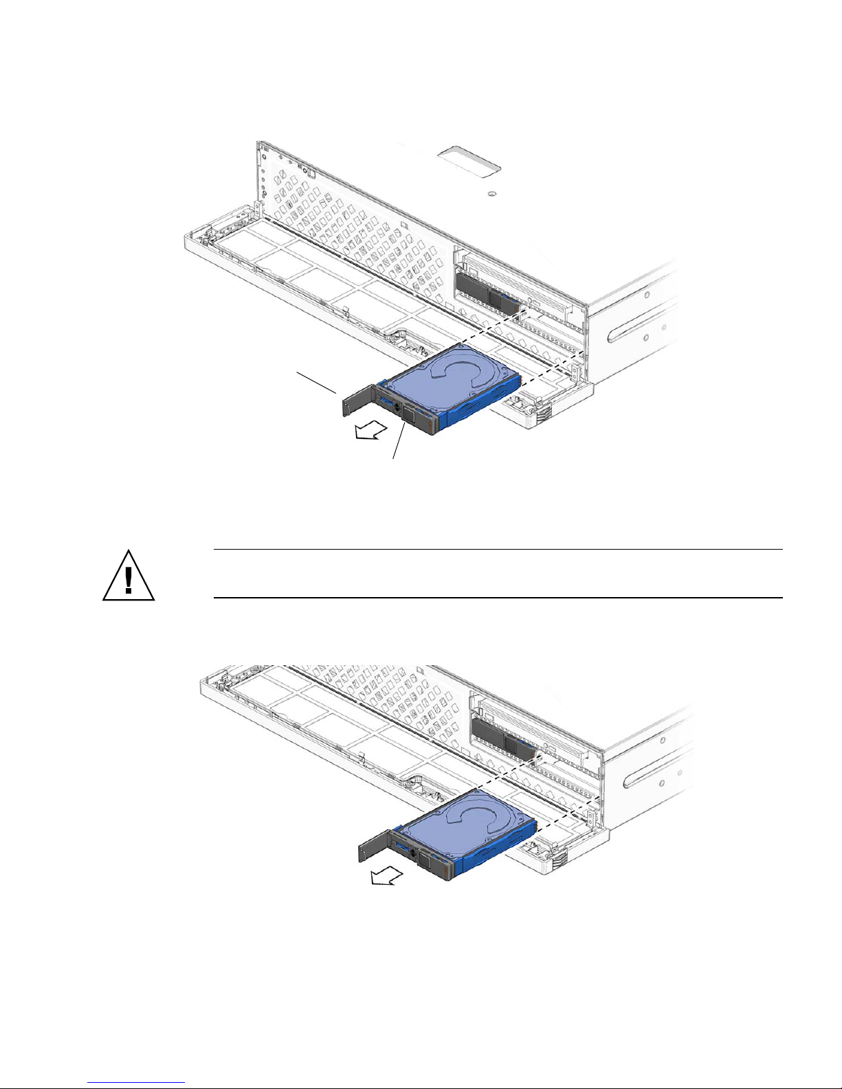
Latch
Latch release
button
FIGURE 3-19 Opening the Hard Drive Latch
Caution – The latch is not an ejector. Do not bend it too far to the left. Doing so can
damage the latch.
5. Grasp the latch and pull the drive out of the drive slot (
FIGURE 3-20 Removing the Hard Drive From the Server
Chapter 3 Maintaining the Netra X4200 M2 Server 45
FIGURE 3-20).
6. Consider your next steps:
■ If you are replacing the hard drive, continue to “Installing a Hard Drive” on
page 46.
■ If you are not replacing the hard drive, perform administrative tasks to
configure the server to operate without the hard drive.
Installing a Hard Drive
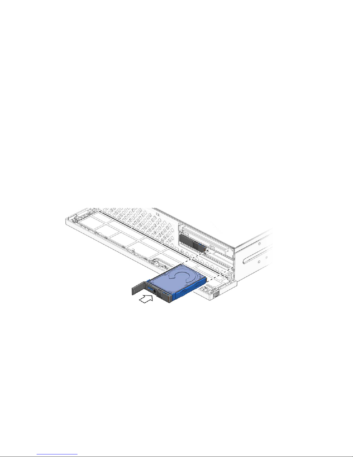
1. Remove the replacement hard drive from its packaging and place the drive on
an antistatic mat.
2. Align the replacement drive to the drive slot.
The hard drive is physically addressed according to the slot in which it is
installed. See
same slot as the drive that was removed.
FIGURE 3-21. It is important to install a replacement drive in the
3. Slide the drive into the bay until it is fully seated (
FIGURE 3-21 Installing the Hard Drive Into the Server
4. Close the latch to lock the drive in place.
5. Close the front bezel (
FIGURE 3-22).
FIGURE 3-21).
46 Netra X4200 M2 Server Service Manual • May 2007

FIGURE 3-22 Closing the Bezel
6. Perform administrative tasks to reconfigure the hard disk drive.
The procedures that you perform at this point depend on how your data is
configured. You might need to partition the drive, create file systems, load data
from backups, or have the drive updated from a RAID configuration.
Replacing the Mass Storage Assembly
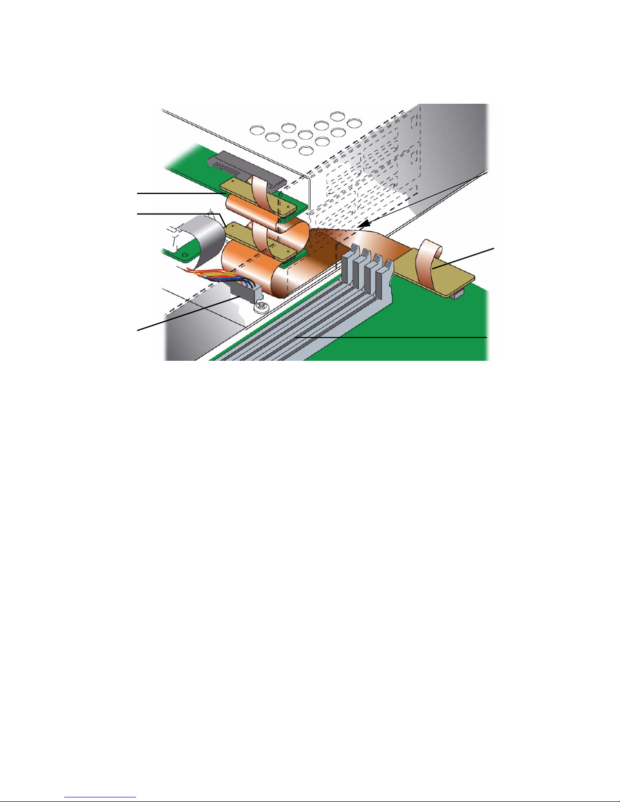
Mass Storage Assembly Connectors
FIGURE 3-23 identifies the five key connections that must be made on the mass
storage assembly. The corresponding connections are:
1. Flex circuit connector
2. System fan connector
3. Ribbon cable connector to the power distribution board
4. Hard drive fan connector
5. PCI tray power cable
Note – Do not remove the DVD connector.
Chapter 3 Maintaining the Netra X4200 M2 Server 47

3
45
2
1
DVD Connection
Do not remove
FIGURE 3-23 Five Key Connections of the Mass Storage Assembly
FIGURE 3-24 shows how the five key connections look when the cables are plugged in
.
System Fan
Connector
Flex Circuit
(4-HDD)
Ribbon cable
Hard Drive Fan Connector
to PDB
PCI Tray
Power Cable
DVD Connection
Do not remove
FIGURE 3-24 Populated Mass Storage Assembly Connectors
FIGURE 3-25 shows an angled perspective of the path of the flex circuit connector
from the motherboard to the 2- and 4-hard drive locations on the hard drive
backplane.
48 Netra X4200 M2 Server Service Manual • May 2007
4-HDD
2-HDD
System Fan
Connector
Note: Flex circuit
cable assembly
passes through
cutout in chassis
wall.
Motherboard
Connection
DIMM locations
FIGURE 3-25 Path of the Flex Cable From Motherboard to 2- and 4-HDD Connections
Removing the Mass Storage Assembly
1. Prepare the server for mass storage assembly removal. See:
■ “Powering Off the Server” on page 28
■ “Disconnecting Cables From the Server” on page 29
■ “Removing the Server From the Rack” on page 30
■ “Performing Antistatic Measures” on page 31
■ “Removing the Top Cover” on page 33
2. Remove the DVD drive and all the hard drives. See:
■ “Removing the DVD Drive” on page 40
■ “Removing a Hard Drive” on page 43
3. Disconnect the following cables from the mass storage assembly and power
distribution board (
■ System fan
■ Hard drive fan
■ PCI tray power cable
FIGURE 3-24):
Chapter 3 Maintaining the Netra X4200 M2 Server 49
■ Flex circuit
■ Ribbon cable to power distribution board (PDB)
4. Move the cables as far out of the way as possible.
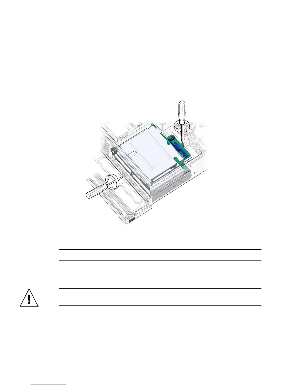
5. Loosen both the screw at the back of the mass storage assembly and the screw
at the front of the chassis (
FIGURE 3-26).
FIGURE 3-26 Loosening the Mass Storage Assembly Screws
Note – The screws are captive and cannot be completely removed.
6. Slide the mass storage assembly back, pivot the back end up, and lift the
assembly out of the chassis (
Caution – As you remove the assembly, be careful that the flex cable does not get
caught on the flex circuit or the PDB ribbon cable.
50 Netra X4200 M2 Server Service Manual • May 2007
FIGURE 3-27).

FIGURE 3-27 Lifting the Mass Storage Assembly From the Chassis
7. Set the mass storage assembly aside on an antistatic mat.
8. Consider your next step:
■ If you removed the mass storage assembly as part of another procedure, return
to that procedure.
■ Otherwise, continue to “Installing the Mass Storage Assembly” on page 51.
Installing the Mass Storage Assembly
1. Remove the replacement mass storage assembly from its packaging and place
it on an antistatic mat.
2. Move the cables as far out of the way as possible.
3. Pivot the front of the mass storage assembly down and lower the assembly
into the chassis, sliding it forward (
FIGURE 3-28).
Chapter 3 Maintaining the Netra X4200 M2 Server 51

FIGURE 3-28 Setting the Mass Storage Assembly Into Place
4. Tighten the screws at the front of the chassis and the back of the mass storage
assembly (
FIGURE 3-29).
FIGURE 3-29 Tightening the Mass Storage Assembly Screws
52 Netra X4200 M2 Server Service Manual • May 2007

5. Connect the following cables to the mass storage assembly (FIGURE 3-24):
■ System fan
■ Hard drive fan
■ PCI tray power cable
■ Flex circuit
■ Ribbon cable to power distribution board
6. Install the DVD drive and the hard drives. See:
■ “Installing the DVD Drive” on page 42
■ “Installing a Hard Drive” on page 46
7. Close the front bezel.
8. Consider your next step:
■ If you installed the mass storage assembly as part of another procedure, return to
that procedure.
■ Otherwise, perform the following tasks to bring the server back online:
■ “Installing the PCI Tray” on page 108
■ “Installing the Top Cover” on page 112
■ “Removing Antistatic Measures” on page 113
■ “Installing the Server Chassis in the Rack” on page 114
■ “Reconnecting Cables to the Server” on page 115
■ “Powering On the Server” on page 116
Replacing the System Fan Assembly
Caution – Netra X4200 M2 fans are not hot swappable; you must power off the
server before replacing. Do not operate the server without fans.
Note – This fan assembly is also referred to as Fan Tray 0.
Chapter 3 Maintaining the Netra X4200 M2 Server 53

Removing the System Fan Assembly
1. Prepare the server for fan assembly removal. See:
■ “Powering Off the Server” on page 28
■ “Disconnecting Cables From the Server” on page 29
■ “Removing the Server From the Rack” on page 30
■ “Performing Antistatic Measures” on page 31
■ “Removing the Top Cover” on page 33
2. Undo the thumbscrew at location J2 and slide the PCI tray back to the fully
open position.
3. Reach down behind the flex circuit.
4. Disconnect the fan assembly cable at connector J3 on the power board by
depressing the connector retention latch while pulling the connector housing
straight up (
FIGURE 3-30).
FIGURE 3-30 Disconnecting the System Fan Assembly Cable
5. Remove the fan assembly cable from the cable guides.
6. Insert your forefinger and thumb into the holes at the top of the fan assembly,
squeeze your fingers together, and lift the fan assembly from the chassis
(
FIGURE 3-31).
54 Netra X4200 M2 Server Service Manual • May 2007

FIGURE 3-31 Lifting the System Fan Assembly From the Chassis
7. Set the fan assembly aside on an antistatic mat.
8. Consider your next step:
■ If you removed the fan assembly as part of another procedure, return to that
procedure.
■ Otherwise, continue to “Installing the System Fan Assembly” on page 55.
Installing the System Fan Assembly
1. Remove the replacement fan assembly from its packaging and place the
assembly on an antistatic mat.
2. Insert your forefinger and thumb into the holes at the top of the fan assembly,
squeeze your fingers together, and lower the fan assembly into the chassis
(
FIGURE 3-32).
Chapter 3 Maintaining the Netra X4200 M2 Server 55

FIGURE 3-32 Lowering the Fan Assembly Into the Chassis
3. Reconnect the system fan assembly cable to connector J3 on the power board
(
FIGURE 3-33).
Note – The connector is not easy to see because it is positioned under the flex
circuit. FIGURE 3-25 shows the flex circuit connection location.
56 Netra X4200 M2 Server Service Manual • May 2007

FIGURE 3-33 Connecting the Fan Assembly Cable
4. Route the fan assembly cable back into the cable guides.
5. Consider your next step:
■ If you installed the fan assembly as part of another procedure, return to that
procedure.
■ Otherwise, perform the following tasks to bring the server back online:
■ “Installing the Top Cover” on page 112
■ “Removing Antistatic Measures” on page 113
■ “Installing the Server Chassis in the Rack” on page 114
■ “Reconnecting Cables to the Server” on page 115
■ “Powering On the Server” on page 116
Chapter 3 Maintaining the Netra X4200 M2 Server 57

Replacing the Hard Drive Fan Assembly
Caution – Netra X4200 M2 fans are not hot swappable; you must power off ther
server before replacing. Do not operate the server without fans.
Note – This fan assembly is also referred to as Fan Tray 1.
Removing the Hard Drive Fan Assembly
1. Prepare the server for hard drive fan removal. See:
■ “Powering Off the Server” on page 28
■ “Disconnecting Cables From the Server” on page 29
■ “Removing the Server From the Rack” on page 30
■ “Performing Antistatic Measures” on page 31
■ “Removing the Top Cover” on page 33
58 Netra X4200 M2 Server Service Manual • May 2007

2. Disconnect the hard drive fan assembly cable from the power board connector
J5. The connector’s location can also be seen in
FIGURE 3-34 Disconnecting the Hard Drive Fan Assembly Cable
FIGURE 3-24.
3. Carefully lift the hard drive fan assembly cable from the cable guides.
4. Push the green release button on the center of the hard drive fan bracket, and
pivot the bracket backward (
FIGURE 3-35 Releasing the Hard Drive Fan Bracket
FIGURE 3-35).
5. Slide the bracket forward and lift the hard drive fan assembly from the chassis
Chapter 3 Maintaining the Netra X4200 M2 Server 59

(FIGURE 3-36).
FIGURE 3-36 Lifting the Hard Drive Fan Assembly From the Chassis
6. Set the hard drive fan assembly aside on an antistatic mat.
7. Continue to “Installing the Hard Drive Fan Assembly” on page 60.
Installing the Hard Drive Fan Assembly
1. Remove the replacement hard drive fan assembly from its packaging and place
the assembly on an antistatic mat.
2. Lower the hard drive fan assembly down, and slide the hard drive fan bracket
back so that the tabs enter the slots (
FIGURE 3-37).
60 Netra X4200 M2 Server Service Manual • May 2007

FIGURE 3-37 Lowering the Hard Drive Fan Assembly
3. Pivot the hard drive fan bracket forward until it clicks (FIGURE 3-38).
FIGURE 3-38 Securing the Hard Drive Fan Bracket
4. Connect the hard drive fan assembly cable to the power board at connector J5
(
FIGURE 3-39).
Chapter 3 Maintaining the Netra X4200 M2 Server 61

FIGURE 3-39 Connecting the Hard Drive Fan Assembly Cable
5. Route the hard drive fan assembly cable back into the cable guides.
6. Perform the following tasks to bring the server back online:
■ “Installing the Top Cover” on page 126
■ “Removing Antistatic Measures” on page 127
■ “Reinstalling the Server Chassis in the Rack” on page 127
■ “Reconnecting Cables to the Server” on page 130
■ “Powering On the Server” on page 131
Replacing the LED Board
Removing the LED Board
1. Prepare the server for LED board removal.
■ “Powering Off the Server” on page 28
■ “Disconnecting Cables From the Server” on page 29
■ “Removing the Server From the Rack” on page 30
■ “Performing Antistatic Measures” on page 31
62 Netra X4200 M2 Server Service Manual • May 2007

■ “Removing the Top Cover” on page 33
■ “Removing the PCI Tray and PCI-E Ribbon Cables” on page 34
2. Remove the DIMM/CPU duct.
See “Removing the DIMM/CPU Duct” on page 68.
3. Remove the system fan assembly.
See “Removing the System Fan Assembly” on page 54.
4. Loosen the thumbscrew of the LED board and swing the board out to the left
(
FIGURE 3-40).
FIGURE 3-40 Removing the LED Board From the Chassis
5. Carefully lift the LED board and cable from the cable clips.
6. Disconnect the cable from the LED board (
Chapter 3 Maintaining the Netra X4200 M2 Server 63
FIGURE 3-41).

FIGURE 3-41 Disconnecting the Cable From the LED Board
7. Set the LED board aside on an antistatic mat.
8. Continue to “Installing the LED Board” on page 64.
Installing the LED Board
1. Remove the replacement LED board from its packaging and place the board on
an antistatic mat.
2. Connect the cable to the LED board (
FIGURE 3-42 Connecting the Cable to the LED Board
FIGURE 3-42).
3. Insert the tab on the LED board into the slot on the chassis (FIGURE 3-43).
64 Netra X4200 M2 Server Service Manual • May 2007

FIGURE 3-43 Inserting the LED Board Tab
4. Swing the LED board right to the chassis and tighten the thumbscrew
(
FIGURE 3-44).
FIGURE 3-44 Securing the LED Board to the Chassis
5. Route the LED board cable back into the cable guides.
6. Install the system fan assembly.
See “Installing the System Fan Assembly” on page 55.
7. Install the DIMM/CPU duct.
See “Installing the DIMM/CPU Duct” on page 69.
8. Perform the following tasks to bring the server back online.
■ “Installing the Top Cover” on page 126
■ “Removing Antistatic Measures” on page 127
■ “Reinstalling the Server Chassis in the Rack” on page 127
■ “Reconnecting Cables to the Server” on page 130
■ “Powering On the Server” on page 131
Chapter 3 Maintaining the Netra X4200 M2 Server 65

Replacing the GRASP Board
Follow these steps to remove and replace the Graphics Redirect and Service
Processor (GRASP) board.
1. Prepare the server for GRASP board removal.
■ “Powering Off the Server” on page 28
■ “Disconnecting Cables From the Server” on page 29
■ “Removing the Server From the Rack” on page 30
■ “Performing Antistatic Measures” on page 31
■ “Removing the Top Cover” on page 33
■ “Removing the PCI Tray and PCI-E Ribbon Cables” on page 34
■ “Removing the PCI-E Cable Hold-Down Bracket” on page 36
Removing the GRASP Board
1. Power off the server as described in “Powering Off the Server” on page 28.
Note – Remove AC/DC power supply unit inlet cables and attach a wrist strap to
the button-snap grounding post inside the chassis just behind the mass storage
assembly (see FIGURE 3-10 for the location).
2. If the server is in a rack, slide it far enough from the rack so that you can
remove the cover. If you cannot safely view and access the component, remove
the server from the rack.
3. Remove the cover as described in “Removing the Top Cover” on page 33.
Caution – There is a power status LED (CR1) on the GRASP board that indicates
whether 3.3V standby power is reaching the GRASP board. The GRASP board is not
hot-pluggable and should never be removed while this LED is lit.
4. Squeeze the plastic standoff that protrudes through the GRASP board to press
the standoff’s locking tabs. See procedure inset 1 in
FIGURE 3-45.
If you have difficulty pressing the locking tabs with your fingers, you can use a
pair of long-nosed pliers.
66 Netra X4200 M2 Server Service Manual • May 2007

Power status
LED CR1
FIGURE 3-45 Removing the GRASP Board From the Motherboard
5. Raise the corner of the GRASP board until it is clear of the locking tab. See
Procedure 2 in
FIGURE 3-45.
6. Pivot the front edge of the GRASP board upward to disengage it from the rear
plastic bracket and to disengage its connector from the motherboard. See
Procedure 3 in
FIGURE 3-45.
Note – Gently lift to avoid bending the GRASP board while removing or installing.
Installing the GRASP Board
To install the GRASP board, reverse the steps you used to remove the GRASP board.
Push firmly on the center of the board to avoid bowing and ensure full mating of the
motherboard connector.
Chapter 3 Maintaining the Netra X4200 M2 Server 67

Replacing the DIMM/CPU Duct
Removing the DIMM/CPU Duct
1. Prepare the server for DIMM/CPU duct removal. See:
■ “Powering Off the Server” on page 28
■ “Disconnecting Cables From the Server” on page 29
■ “Removing the Server From the Rack” on page 30
■ “Performing Antistatic Measures” on page 31
■ “Removing the Top Cover” on page 33
■ “Removing the PCI Tray and PCI-E Ribbon Cables” on page 34
2. Raise the DIMM/CPU duct into the vertical position (
FIGURE 3-46).
FIGURE 3-46 Raising the DIMM/CPU Duct
68 Netra X4200 M2 Server Service Manual • May 2007

3. Unhook the duct from the pins of the chassis (FIGURE 3-47).
FIGURE 3-47 Unhooking the DIMM/CPU Duct From the Pins of the Chassis
4. Lift the duct out of the chassis, and set it aside on an antistatic mat.
5. Consider your next step:
■ If you removed the DIMM/CPU duct as part of another procedure, return to
that procedure.
■ Otherwise, continue to “Installing the DIMM/CPU Duct” on page 69.
Installing the DIMM/CPU Duct
1. Remove the replacement DIMM/CPU duct from its packaging.
2. Position the duct vertically over the pins of the chassis and hook the duct to
the pins of the chassis (
3. Lower the duct down to the horizontal position (
FIGURE 3-47).
FIGURE 3-48).
Chapter 3 Maintaining the Netra X4200 M2 Server 69

FIGURE 3-48 Lowering the DIMM/CPU Duct
4. Consider your next step:
■ If you installed the DIMM/CPU duct as part of another procedure, return to
that procedure.
■ Otherwise, perform the following tasks to bring the server back online:
■ “Installing the Top Cover” on page 126
■ “Removing Antistatic Measures” on page 127
■ “Reinstalling the Server Chassis in the Rack” on page 127
■ “Reconnecting Cables to the Server” on page 130
■ “Powering On the Server” on page 131
70 Netra X4200 M2 Server Service Manual • May 2007

Replacing Memory Modules (DIMMs)
Follow these steps to remove and replace the server’s dual inline memory modules
(DIMMs).
Removing a DIMM
1. Prepare the server for DIMM removal. See:
■ “Powering Off the Server” on page 28
■ “Disconnecting Cables From the Server” on page 29
■ “Removing the Server From the Rack” on page 30
■ “Performing Antistatic Measures” on page 31
■ “Removing the Top Cover” on page 33
Note – You will only need to slide the PCI tray back for this procedure.
2. Flip the DIMM/CPU duct open. DIMMs are located underneath. See
FIGURE 3-49.
FIGURE 3-49 Flipping the DIMM/CPU Duct open
3. Identify the DIMM to remove and press the ejector levers open, releasing the
DIMM (
FIGURE 3-50).
Chapter 3 Maintaining the Netra X4200 M2 Server 71

FIGURE 3-50 Releasing and removing the DIMM
For the Netra X4200 M2 server, you can view the DIMM fault LEDs without the
power cords attached. These LEDs can be lit by a capacitor on the motherboard
for up to one minute. To light the DIMM fault LEDs, push the small button on
the motherboard labeled “DIMM SW2.” See
FIGURE 3-51 for the numbering and
pairing of the Netra X4200 M2 DIMM slots.
Note – To push the DIMM SW2 button, the PCI Tray must be removed and the
button must be pushed through the hole in the PCI-E cable hold-down bracket.
Netra X4200 M2 DIMM Population Rules
The DIMM population rules for the Netra X4200 M2 server are as follows:
■ The Netra X4200 M2 server uses only DDR2 DIMMs.
■ Each CPU can support a maximum of four DDR2 DIMMs.
■ Each pair of DIMMs must be identical (same manufacturer and capacity).
■ The DIMM slots are paired and the DIMMs must be installed in pairs (A1 and B1,
A0 and B0). The memory sockets are colored black or white to indicate which
slots are paired by matching colors.
72 Netra X4200 M2 Server Service Manual • May 2007

■ CPUs with only a single pair of DIMMs must have those DIMMs installed in that
CPU’s white DIMM slots (A1 and B1).
Back panel of server
DIMM SW2
DIMM A0
DIMM B0
DIMM A1
DIMM B1
Pair 0 = DIMM B1 + DIMM A1
Pair 1 = DIMM B0 + DIMM A0
FIGURE 3-51 Netra X4200 M2 DIMM Slot Numbering and Pairing
CPU1 CPU0
FT0
FM0
FT0
FM0
Cable hold-down
bracket
DIMM A0
DIMM B0
DIMM A1
DIMM B1
DIMM fault LEDs
in DIMM ejector levers
FT0
FM2
Supported DIMM Configurations For Netra X4200 M2
TABLE 3-1 Supported DIMM Configurations for Netra X4200 M2
Slot A1 Slot B1 Slot A0 Slot B0 Total Memory Per CPU
1GB 1GB 0 02GB
1GB 1GB 1GB 1GB 4GB
2GB 2GB 1GB 1GB 6GB
4GB 4GB 1GB 1GB 10GB
2GB 2GB 0 04GB
2GB 2GB 2GB 2GB 8GB
Chapter 3 Maintaining the Netra X4200 M2 Server 73

TABLE 3-1 Supported DIMM Configurations for Netra X4200 M2 (Continued)
Slot A1 Slot B1 Slot A0 Slot B0 Total Memory Per CPU
4GB 4GB 2GB 2GB 12GB
4GB 4GB 0 08GB
4GB 4GB 4GB 4GB 16GB
4. Set the DIMM aside on an antistatic mat.
5. Repeat steps 3 and 4 for all DIMMs to be removed.
6. Consider your next step:
■ If you removed the DIMMs as part of another procedure, return to that
procedure.
■ If you are to install DIMMs, continue to “Installing a DIMM” on page 74.
■ If you are to only remove DIMMs:
a. Install the DIMM/CPU duct.
See “Installing the DIMM/CPU Duct” on page 69.
b. Perform the following tasks to bring the server back online:
■ “Installing the Top Cover” on page 126
■ “Removing Antistatic Measures” on page 127
■ “Reinstalling the Server Chassis in the Rack” on page 127
■ “Reconnecting Cables to the Server” on page 130
■ “Powering On the Server” on page 131
Installing a DIMM
1. Flip the DIMM/CPU duct open. DIMMs are located underneath. See
FIGURE 3-49.
Note – Locate DIMM numbering on the bottom of the air duct.
2. Ensure that the DIMM slot ejectors at each end of the memory socket are fully
open (rotated outward) to accept the new DIMM.
3. Align the notch in the bottom edge of the DIMM with the key in the DIMM
socket. See
FIGURE 3-52.
74 Netra X4200 M2 Server Service Manual • May 2007

4. Press down evenly on both top corners of the DIMM until the ejectors snap
over the cutouts in the left and right edges of the DIMM (
FIGURE 3-52).
Note – Install DIMMs in pairs into alternate slots.
FIGURE 3-52 Inserting the DIMM Into the Slot
5. Repeat steps 3 through 5 for all DIMMs to be installed.
6. Consider your next step:
■ If you installed DIMMs as part of another procedure, return to that procedure.
■ If you are to only install DIMMs:
a. Install the DIMM/CPU duct.
See “Installing the DIMM/CPU Duct” on page 69.
b. Perform the following tasks to bring the server back online:
■ “Installing the Top Cover” on page 126
■ “Removing Antistatic Measures” on page 127
■ “Reinstalling the Server Chassis in the Rack” on page 127
■ “Reconnecting Cables to the Server” on page 130
■ “Powering On the Server” on page 131
Chapter 3 Maintaining the Netra X4200 M2 Server 75

Replacing a CPU and Heatsink
Follow these steps to remove and replace a CPU and its heatsink in a Netra X4200
M2 server.
Supported components and their part numbers are subject to change over time. For
the most up-to-date list of replaceable components for these servers, see the
following URL:
http://sunsolve.sun.com/handbook_pub/Systems/
Caution – Some AMD CPUs are released as Special Editions, which might differ in
wattage from non-Special Edition versions of the CPU. Do not mix Special Edition
CPUs with non-Special Edition versions. Always make sure that all CPUs in the
server have the same part number.
Removing a Netra X4200 M2 CPU and Heatsink
1. Power off the server as described in “Powering Off the Server” on page 28.
2. If the server is in a rack, slide it far enough from the rack so that you can
remove the main cover. If you cannot safely view and access the component,
remove the server from the rack.
3. Remove the top cover as described in “Removing the Top Cover” on page 33.
4. Identify which CPU and heatsink you are replacing.
The designation of the two CPUs in the server is shown in
fault LED on the motherboard for each CPU (see
location):
■ LED is off: CPU is operating properly.
■ LED is lit (amber): CPU has encountered a voltage or heat error condition.
FIGURE 3-53 for the LED
FIGURE 3-53. There is a
76 Netra X4200 M2 Server Service Manual • May 2007

Back panel of server
DIMM 3
DIMM 1
DIMM 2
DIMM 0
DIMM 3
DIMM 1
DIMM 2
DIMM 0
CPU1 CPU0
CPU fault LEDs (2)
FT0
FM0
FIGURE 3-53 CPU and Fault LED Locations
FT1
FM1
FT1
FM2
5. Remove the CPU and heatsink from the motherboard:
a. Hold down on the top of the heatsink to prevent it from tipping unevenly
while you alternately loosen the four spring-loaded mounting screws that
secure the heatsink to the motherboard. Turn the screws 180-degrees at a
time, then remove the screws when they are detached. See
FIGURE 3-55.
Chapter 3 Maintaining the Netra X4200 M2 Server 77
FIGURE 3-54 and

FIGURE 3-54 Location of the Heatsink Screws
The four screws
are circled in red.
FIGURE 3-55 Removing the Heatsink
b. Twist the heatsink slightly to lift it off of the board. Turn the heatsink
upside down and allow the spring in each of the four mounting holes to
fall out into your hand.
78 Netra X4200 M2 Server Service Manual • May 2007

Note – Set the heatsink upside down on a clean, flat surface to prevent the thermal
grease from contaminating other components.
c. Pull the CPU socket lever slightly away from the socket. See
FIGURE 3-56.
d. Pivot the lever up, into the fully open, vertical position.
FIGURE 3-56 Releasing the CPU Socket Lever
e. Open the hinged plate that covers the CPU until it is in the fully open
position and lift the CPU out of the socket, leaving the lever in the vertical,
open position. See
FIGURE 3-57.
Chapter 3 Maintaining the Netra X4200 M2 Server 79

FIGURE 3-57 Removing the CPU From the Socket
Installing a Netra X4200 M2 CPU and Heatsink
1. Install the new CPU and heatsink:
Note – Mixing CPU speeds or mixing dual-core CPUs with single-core CPUs is not
supported. Use two identical CPUs in your server.
a. Unpack the new CPU and heatsink.
b. Ensure that the CPU socket release lever and retainer plate are in the fully
open position.
c. Align the CPU in the socket as shown in
Note – Use the alignment keys in the CPU socket to match the alignment notches on
the sides of the CPU. See inset of FIGURE 3-57.
d. Gently set the CPU onto the pins in the socket.
80 Netra X4200 M2 Server Service Manual • May 2007
FIGURE 3-57.

e. When the CPU is fully seated in the socket, pivot the hinged retainer plate
down onto the top of the CPU.
f. Pivot the release lever down and into the locked position, at the side of the
socket.
The release lever must lock down the retainer plate as you close the lever. See
FIGURE 3-56 for a view of how the lever locks down the edge of the plate.
g. If you are reinstalling an existing CPU or heatsink, use an alcohol pad to
clean all old thermal grease from the component surface.
Caution – Ensure that the thermal grease in the syringe supplied with the CPU is
pliable and not stiff. If your syringe of grease has aged, the grease might be too stiff
to adequately spread out and ensure thermal conductance.
h. Use one syringe of thermal grease (0.5 g) to carefully apply grease to the top
of the CPU in three lines in the pattern shown in
CPU surface
FIGURE 3-58.
Lines of thermal grease
FIGURE 3-58 Required Pattern for Thermal Grease Application
2. Turn the heatsink upright and reinstall the four springs and mounting bolts.
Caution – Avoid moving the heatsink after it has contacted the top of the CPU. Too
much movement could disturb the layer of thermal grease, leading to component
damage.
3. Carefully position and align the heatsink over the CPU.
Chapter 3 Maintaining the Netra X4200 M2 Server 81

Note – The heatsink is not symmetrical and it must be aligned before you place it
on the CPU. Note that the half of the Sun Microsystems logo imprinted on the top of
the heatsink will create a complete logo when correctly aligned with the adjacent
heatsink.
4. Lower the heatsink onto the CPU, aligning the mounting bolts with their holes
on the motherboard.
5. Alternately tighten the four heatsink mounting screws 180-degrees at a time
until each spring is completely compressed.
Replacing the Motherboard Assembly
Removing the Motherboard Assembly
1. Prepare the server for motherboard assembly removal. See:
■ “Powering Off the Server” on page 28
■ “Disconnecting Cables From the Server” on page 29
■ “Removing the Server From the Rack” on page 30
■ “Performing Antistatic Measures” on page 31
2. Remove the following components:
■ Top cover – “Removing the Top Cover” on page 33
■ PCI tray – “Removing the PCI Tray and PCI-E Ribbon Cables” on page 34
■ Cable hold-down bracket – “Removing the PCI-E Cable Hold-Down Bracket”
on page 36
■ Cables for PCI-E – “Removing the PCI Tray and PCI-E Ribbon Cables” on
page 34
■ DIMM/CPU duct – “Removing the DIMM/CPU Duct” on page 68
■ System Fan assembly – “Removing the System Fan Assembly” on page 54
■ DIMMs – “Removing a DIMM” on page 71
■ Alarm board – “Replacing the Alarm Board” on page 103
■ Graphics Redirect and Service Processor (GRASP) board – “Removing the
GRASP Board” on page 66.
82 Netra X4200 M2 Server Service Manual • May 2007

3. Disconnect the cables from the following connectors on the motherboard
assembly (
■ Flex Circuit (J7)
■ Front I/O (J23)
FIGURE 3-59):
Flex Circuit (J7)
Front I/O (J23)
FIGURE 3-59 Disconnecting the Cables From the Motherboard Assembly
4. Use an 8mm nut-driver to remove the two bus-bar nuts and six other screws
that secure the motherboard assembly to the chassis. See
FIGURE 3-60.
Chapter 3 Maintaining the Netra X4200 M2 Server 83

FIGURE 3-60 Motherboard Securing Screws and Bus-Bar Screw Locations
5. Use the lifting handle to raise the forward edge of the board until it has
cleared the bus-bar studs.
Caution – When lifting the board, use caution to avoid damaging the light pipes
and connectors on the rear edge of the motherboard.
6. Slide the board toward the front of the chassis until the connectors and light
pipes are clear of the chassis back panel gasketing. Then raise the motherboard
and remove it from the chassis.
84 Netra X4200 M2 Server Service Manual • May 2007

FIGURE 3-61 Removing the Motherboard Assembly From the Chassis
7. Set the motherboard assembly aside on an antistatic mat.
8. Continue to “Installing the Motherboard Assembly” on page 86.
Note – After you replace the motherboard FRU, you must use the servicetool
command to update FRU information about the motherboard. See “Servicetool FRU
Update Procedure” on page 117.
Chapter 3 Maintaining the Netra X4200 M2 Server 85

Installing the Motherboard Assembly
1. Remove the replacement motherboard assembly from its packaging and place
the assembly on an antistatic mat.
2. Lower the left edge of the motherboard assembly into the chassis, then the
entire board, and while slightly elevated, slide the motherboard assembly to
the back of the chassis (
into the rear gasketing.
FIGURE 3-62), carefully seating the rear I/O connectors
FIGURE 3-62 Installing the Motherboard Assembly Into the Chassis
3. Align the motherboard assembly screw holes over the chassis standoffs.
4. Install the two bus bar screws and five other screws (
5. Reconnect the cables to the following connectors on the motherboard
assembly:
■ Flex Circuit (J7)
■ Front I/O (J23)
86 Netra X4200 M2 Server Service Manual • May 2007
FIGURE 3-60).
 Loading...