


Sun Netra T5220 Server
Service Manual
Part No.: E21359-02
January 2012

Copyright ©2008, 2012,Oracle and/orits affiliates.All rightsreserved.
This softwareand related documentationare provided undera licenseagreement containingrestrictions on use and disclosure and areprotected by
intellectual propertylaws. Exceptas expressly permittedin yourlicense agreementor allowedby law,you maynot use,copy, reproduce, translate,
broadcast, modify, license,transmit, distribute,exhibit, perform,publish, ordisplay anypart, inany form,or byany means.Reverse engineering,
disassembly, or decompilation of this software, unlessrequired by law for interoperability, is prohibited.
The informationcontained hereinis subjectto changewithout noticeand isnot warrantedto beerror-free.If youfind anyerrors, please report them to us
in writing.
If thisis softwareor related softwaredocumentation thatis delivered tothe U.S.Government oranyone licensingit onbehalf ofthe U.S.Government, the
following noticeis applicable:
U.S. GOVERNMENTRIGHTS. Programs,software, databases, and related documentation and technical data deliveredto U.S.Government customers
are "commercial computersoftware" or"commercial technical data" pursuant to the applicable Federal Acquisition Regulation and agency-specific
supplemental regulations.As such,the use,duplication, disclosure, modification,and adaptationshall besubject tothe restrictionsand licenseterms set
forth inthe applicableGovernment contract,and, tothe extentapplicable bythe termsof theGovernment contract,the additionalrights setforth inFAR
52.227-19, CommercialComputer Software License(December 2007).Oracle America,Inc., 500Oracle Parkway, Redwood City, CA 94065.
This software or hardware is developed for general use ina varietyof informationmanagement applications. It is not developed orintended foruse inany
inherently dangerous applications,including applicationswhich maycreate arisk ofpersonal injury. Ifyou usethis softwareor hardware indangerous
applications, thenyou shallbe responsibleto takeall appropriate fail-safe,backup, redundancy, andother measuresto ensure itssafe use.Oracle
Corporation andits affiliatesdisclaim anyliability forany damagescaused byuse ofthis software orhardware in dangerous applications.
Oracle andJava areregistered trademarks of Oracle and/or its affiliates.Other namesmay betrademarks oftheir respective owners.
Intel andIntel Xeonare trademarksor registered trademarksof IntelCorporation. AllSPARC trademarks areused underlicense andare trademarksor
registered trademarks of SPARCInternational, Inc. AMD, Opteron, theAMD logo,and theAMD Opteron logo are trademarksor registered trademarksof
Advanced MicroDevices. UNIXis aregistered trademark of The Open Group.
This software or hardware and documentation may provide access to or information on content, products, and services from third parties. Oracle
Corporation and its affiliates are not responsible for and expressly disclaim all warranties of any kind with respect to third-party content, products, and
services. Oracle Corporation and its affiliates will not be responsible for any loss, costs, or damages incurred due to your access to or use of third-party
content, products, or services.
Copyright ©2008, 2012,Oracle et/ouses affiliés.Tous droits réservés.
Ce logicielet ladocumentation quil’accompagne sontprotégés parles loissur lapropriété intellectuelle. Ils sont concédés sous licence et soumis à des
restrictions d’utilisationet dedivulgation. Saufdisposition devotre contrat de licence ou de la loi, vous ne pouvez pas copier, reproduire, traduire,
diffuser, modifier, breveter, transmettre,distribuer, exposer, exécuter,publier ouafficher le logiciel, même partiellement, sous quelque forme et par
quelque procédéque cesoit. Parailleurs, ilest interdit deprocéder àtoute ingénierieinverse dulogiciel, dele désassemblerou dele décompiler, excepté à
des finsd’interopérabilité avecdes logicielstiers outel queprescrit par la loi.
Les informationsfournies dansce documentsont susceptiblesde modificationsans préavis.Par ailleurs,Oracle Corporationne garantitpas qu’elles
soient exemptesd’erreurs etvous invite,le caséchéant, àlui enfaire part par écrit.
Si celogiciel, oula documentationqui l’accompagne,est concédésous licenceau Gouvernementdes Etats-Unis,ou àtoute entitéqui délivrela licencede
ce logicielou l’utilisepour lecompte duGouvernement desEtats-Unis, lanotice suivantes’applique :
U.S. GOVERNMENTRIGHTS. Programs,software, databases, and related documentation and technical data deliveredto U.S.Government customers
are "commercial computersoftware" or"commercial technical data" pursuant to the applicable Federal Acquisition Regulation and agency-specific
supplemental regulations. As such, theuse, duplication,disclosure, modification, and adaptation shall be subject to the restrictions and license terms set
forth inthe applicableGovernment contract,and, tothe extentapplicable bythe termsof theGovernment contract,the additionalrights setforth inFAR
52.227-19, CommercialComputer Software License(December 2007). Oracle America, Inc.,500 OracleParkway, Redwood City, CA 94065.
Ce logicielou matériela étédéveloppé pourun usagegénéral dansle cadred’applications degestion desinformations. Celogiciel oumatériel n’estpas
conçu nin’est destinéà êtreutilisé dansdes applicationsà risque,notamment dansdes applicationspouvant causerdes dommagescorporels. Si vous
utilisez celogiciel oumatériel dansle cadred’applications dangereuses, ilest devotre responsabilité deprendre toutes les mesures de secours, de
sauvegarde, deredondance et autres mesures nécessaires à son utilisation dans des conditions optimales de sécurité. Oracle Corporation et ses affiliés
déclinent touteresponsabilité quantaux dommagescausés parl’utilisation dece logicielou matérielpour cetype d’applications.
Oracle etJava sontdes marquesdéposées d’OracleCorporation et/oude sesaffiliés.Tout autre nommentionné peutcorrespondre à des marques
appartenant àd’autres propriétaires qu’Oracle.
Intel etIntel Xeonsont desmarques oudes marques déposéesd’Intel Corporation.Toutes les marques SPARC sont utilisées sous licence et sont des
marques oudes marques déposéesde SPARC International, Inc. AMD, Opteron, le logo AMD et le logo AMD Opteron sontdes marquesou desmarques
déposées d’AdvancedMicro Devices.UNIX estune marque déposéed’The OpenGroup.
Ce logicielou matérielet ladocumentation quil’accompagne peuventfournir desinformations oudes liensdonnant accèsà descontenus, desproduits et
des servicesémanant detiers. OracleCorporation etses affiliésdéclinent touteresponsabilité ou garantie expresse quant aux contenus, produits ou
services émanantde tiers.En aucuncas, OracleCorporation etses affiliésne sauraientêtre tenus pour responsables des pertes subies, des coûts
occasionnés oudes dommagescausés parl’accès àdes contenus,produits ouservices tiers,ou àleur utilisation.
Please
Recycle

Contents
Preface ix
1. Server Diagnostics 1–1
1.1 Fault on Initial Power Up 1–1
1.2 Server Diagnostics Overview 1–2
1.2.1 Memory Configuration and Fault Handling 1–6
1.2.1.1 Memory Configuration 1–7
1.2.1.2 Memory Fault Handling 1–7
1.2.1.3 Troubleshooting Memory Faults 1–8
1.3 Using LEDs to Identify the State of Devices 1–8
1.3.1 Front and Rear Panel LEDs 1–8
1.3.2 Hard Drive LEDs 1–12
1.3.3 Power Supply LEDs 1–12
1.3.4 Ethernet Port LEDs 1–13
1.4 Using the Service Processor Firmware for Diagnosis and Repair
Verification 1–14
1.4.1 Using the ALOM CMT Compatibility CLI in ILOM 1–16
1.4.2 Creating an ALOM CMT CLI Shell 1–17
1.4.3 Running ALOM CMT CLI Service-Related Commands 1–18
1.4.3.1 Connecting to ALOM CMT CLI 1–18
iii

1.4.3.2 Switching Between the System Console and Service
Processor 1–19
1.4.3.3 Service-Related ALOM CMT CLI Commands 1–19
1.4.4 Displaying System Faults 1–21
1.4.5 Manually Cleaning PSH Diagnosed Faults 1–23
1.4.6 Displaying the Server’s Environmental Status 1–23
1.4.7 Displaying FRU Information 1–25
1.5 Running POST 1–27
1.5.1 Controlling How POST Runs 1–27
1.5.2 Changing POST Parameters 1–30
1.5.3 Reasons to Run POST 1–31
1.5.3.1 Verifying Hardware Functionality 1–31
1.5.3.2 Diagnosing the System Hardware 1–31
1.5.4 Running POST in Maximum Mode 1–31
1.5.5 Clearing POST Detected Faults 1–35
1.6 Using the Solaris Predictive Self-Healing Feature 1–37
1.6.1 Identifying PSH Detected Faults 1–38
1.6.1.1 Using the fmdump Command to Identify Faults 1–38
1.6.2 Clearing PSH Detected Faults 1–40
1.7 Collecting Information From Solaris OS Files and Commands 1–42
1.7.1 Checking the Message Buffer 1–42
1.7.2 Viewing System Message Log Files 1–42
1.8 Managing Components With Automatic System Recovery Commands 1–
43
1.8.1 Displaying System Components 1–44
1.8.2 Disabling Components 1–45
1.8.3 Enabling Disabled Components 1–46
1.9 Exercising the System With SunVTS Software 1–46
1.9.1 Checking Whether SunVTS Software Is Installed 1–46
iv Sun Netra T5220 Server Service Manual • January 2012

1.9.2 Exercising the System Using SunVTS Software 1–47
1.9.3 Exercising the System With SunVTS Software 1–48
1.10 Obtaining the Chassis Serial Number 1–51
1.11 Additional Service Related Information 1–52
2. Preparing for Service 2–1
2.1 Safety Information 2–1
2.1.1 Safety Symbols 2–1
2.1.2 Electrostatic Discharge Safety 2–2
2.1.2.1 Use an Antistatic Wrist Strap 2–2
2.1.2.2 Use an Antistatic Mat 2–2
2.2 Required Tools 2–3
2.3 Prerequisite Tasks for Component Replacement 2–3
2.3.1 Powering Off the Server 2–3
2.3.2 Disconnecting Cables From the Server 2–4
2.3.3 Removing the Server From the Rack 2–5
2.3.4 Performing Antistatic Measures 2–8
2.3.5 Removing the Top Cover 2–8
2.3.6 Removing the PCI Mezzanine 2–9
2.4 Field-Replaceable Units 2–11
3. Replacing Storage Components 3–1
3.1 Replacing a Hard Drive 3–1
3.1.1 Removing a Hard Drive 3–2
3.1.2 Installing a Hard Drive 3–5
3.2 Replacing the Optical Media Drive 3–6
3.2.1 Removing the Optical Media Drive 3–6
3.2.2 Installing the Optical Media Drive 3–7
3.3 Replacing the Media Bay Assembly 3–8
Contents v

3.3.1 Removing the Media Bay Assembly 3–8
3.3.2 Installing the Media Bay Assembly 3–11
4. Replacing Motherboard Assembly Components 4–1
4.1 Powering Off and Powering On the Server 4–1
4.2 Replacing PCI-X, PCIe/XAUI Cards 4–2
4.2.1 PCI Card Retainers 4–2
4.2.2 Replacing PCI-X 4 and PCIe 5 Cards 4–5
▼ To Remove the PCI-X 4 and PCIe 5 Cards 45
▼ To Install PCI-X 4 and PCIe 5 Cards 47
4.2.3 Replacing the PCI-X 3 Card 4–8
▼ To Remove the PCI-X 3 Card 49
▼ To Install the PCI-X 3 Card 49
4.2.4 Replacing the Lower PCIe/XAUI Cards 4–11
▼ To Remove the Lower PCIe/XAUI Cards 411
4.2.5 Installing the Lower PCIe/XAUI Cards 4–12
4.3 Cabling the Sun Storage 6 Gb SAS PCIe RAID HBA, Internal 4–15
▼ Cable the Sun Storage 6 Gb SAS PCIe RAID HBA, Internal 4-15
4.4 Replacing the Air Duct 4–17
4.4.1 Removing the Air Duct 4–17
4.4.2 Installing the Air Duct 4–18
4.5 FB-DIMM Layout 4–19
4.6 Replacing FB-DIMMs 4–23
4.6.1 Locating a Faulty FB-DIMM 4–24
4.6.2 Removing FB-DIMMs 4–24
4.6.3 Installing FB-DIMMs 4–26
4.6.4 Verifying Successful Replacement of a Faulty FB-DIMM 4–28
4.7 Replacing the Battery 4–30
4.7.1 Removing the Battery 4–30
vi Sun Netra T5220 Server Service Manual • January 2012

4.7.2 Installing the Battery 4–31
4.8 Replacing the NVRAM 4–32
4.8.1 Removing the NVRAM 4–32
4.8.2 Installing the NVRAM 4–33
4.9 Replacing the SCC Module 4–35
4.9.1 Removing the SCC Module 4–35
4.9.2 Installing the SCC Module 4–35
4.10 Replacing the Motherboard Assembly 4–36
4.10.1 Removing the Motherboard Assembly 4–36
4.10.2 Installing the Motherboard Assembly 4–39
5. Replacing Chassis Components 5–1
5.1 Replacing the Air Filter 5–1
5.1.1 Removing the Air Filter 5–1
5.1.2 Installing the Air Filter 5–2
5.2 Replacing a Power Supply 5–3
5.2.1 Removing a Power Supply 5–4
5.2.2 Installing a Power Supply 5–6
5.3 Replacing the System Fan Assembly (FT0) 5–6
5.3.1 Removing the System Fan Assembly 5–7
5.3.2 Installing the System Fan Assembly 5–8
5.4 Replacing the Hard Drive Fan Assembly (FT1) 5–9
5.4.1 Removing the Hard Drive Fan Assembly 5–10
5.4.2 Installing the Hard Drive Fan Assembly 5–12
5.5 Replacing the FB-DIMM Fan Assembly (FT2) 5–14
5.5.1 Removing the FB-DIMM Fan Assembly 5–14
5.5.2 Installing the FB-DIMM Fan Assembly 5–14
5.6 Replacing the Alarm Board 5–15
5.6.1 Removing the Alarm Board 5–15
Contents vii

5.6.2 Installing the Alarm Board 5–16
5.7 Replacing the LED Board 5–17
5.7.1 Removing the LED Board 5–17
5.7.2 Installing the LED Board 5–19
5.8 Replacing the Power Board 5–22
5.8.1 Removing the Power Board 5–22
5.8.2 Installing the Power Board 5–24
6. Finishing Up 6–1
6.1 Tasks for Finishing Up 6–1
6.1.1 Installing the PCI Mezzanine 6–1
6.1.2 Installing the Top Cover 6–3
6.1.3 Removing Antistatic Measures 6–4
6.1.4 Reinstalling the Server Chassis in the Rack 6–5
6.1.5 Reconnecting Cables to the Server 6–7
6.1.6 Powering On the Server 6–8
A. Signal Pinouts A–1
A.1 Gigabit Ethernet Ports A–1
A.2 Network Management Port A–2
A.3 Serial Ports A–3
A.3.1 Serial Management Port A–3
A.3.1.1 RJ-45 to DB-9 Adapter Crossovers A–4
A.3.1.2 RJ-45 to DB-25 Adapter Crossovers A–5
A.3.2 Serial Port TTYA A–5
A.4 Alarm Port A–6
A.5 USB Ports A–7
Index Index–1
viii Sun Netra T5220 Server Service Manual • January 2012

Preface
This manual describes how to troubleshoot the server and how to remove and install
replaceable components. This manual is written for technicians, system
administrators, authorized service providers, and users with advanced experience
troubleshooting and replacing hardware.
■ “Product Notes” on page ix
■ “Related Documentation” on page x
■ “Feedback” on page x
■ “Support and Accessibility” on page x
Product Notes
For late-breaking information and known issues about this product, refer to the
products notes at:
http://docs.oracle.com/cd/E19350-01/index.html
ix

Related Documentation
Documentation Link
All Oracle products http://www.oracle.com/documentation
Sun Netra T5220 Server http://docs.oracle.com/cd/E19350-01/index.html
Oracle Solaris OS and systems
software library
http://www.oracle.com/technetwork/indexes/documentation/
index.html#sys_sw
Feedback
Provide feedback about this documentation at:
http://www.oracle.com/goto/docfeedback
Support and Accessibility
Description Links
Access electronic support through
My Oracle Support
http://support.oracle.com
For hearing impaired:
http://www.oracle.com/accessibility/support.html
Learn about Oracle’s commitment to
accessibility
x Sun Netra T5220 Server Service Manual • January 2012
http://www.oracle.com/us/corporate/accessibility/
index.html

CHAPTER
1
Server Diagnostics
This chapter describes the diagnostics that are available for monitoring and
troubleshooting the server.
The following topics are covered:
■ Section 1.1, “Fault on Initial Power Up” on page 1-1
■ Section 1.2, “Server Diagnostics Overview” on page 1-2
■ Section 1.3, “Using LEDs to Identify the State of Devices” on page 1-8
■ Section 1.4, “Using the Service Processor Firmware for Diagnosis and Repair
Verification” on page 1-14
■ Section 1.5, “Running POST” on page 1-27
■ Section 1.6, “Using the Solaris Predictive Self-Healing Feature” on page 1-37
■ Section 1.7, “Collecting Information From Solaris OS Files and Commands” on
page 1-42
■ Section 1.8, “Managing Components With Automatic System Recovery
Commands” on page 1-43
■ Section 1.9, “Exercising the System With SunVTS Software” on page 1-46
■ Section 1.10, “Obtaining the Chassis Serial Number” on page 1-51
■ Section 1.11, “Additional Service Related Information” on page 1-52
1.1 Fault on Initial Power Up
If you have installed the server, and upon initial power up, you see errors indicating
faults with the Fully Buffered DIMMs (FB-DIMMs), PCI cards, or other components,
the suspect component might have become loosened or ajar during shipment.
1-1

Conduct a visual inspection of the server internals and its components. Remove the
top cover and physically reseat the cable connections, the PCI cards, and the
FB-DIMMs. See:
■ Section 2.3, “Prerequisite Tasks for Component Replacement” on page 2-3
■ Section 4.2, “Replacing PCI-X, PCIe/XAUI Cards” on page 4-2
■ Section 4.6, “Replacing FB-DIMMs” on page 4-23.
If performing these tasks is not successful, then continue to Section 1.2, “Server
Diagnostics Overview” on page 1-2.
1.2 Server Diagnostics Overview
There are a variety of diagnostic tools, commands, and indicators you can use to
monitor and troubleshoot a server:
■ LEDs – These indicators provide a quick visual notification of the status of the
server and of some of the FRUs.
■ Fault management architecture – FMA provides simplified fault diagnostics
through use of the /var/adm/messages file, the fmdump command, and a Sun
Microsystems web site.
■ ILOM firmware –This system firmware runs on the service processor. In addition
to providing the interface between the hardware and OS, ILOM also tracks and
reports the health of key server components. ILOM works closely with POST and
Solaris Predictive Self-Healing technology to keep the system up and running
even when there is a faulty component.
■ Power-on self-test (POST) – POST performs diagnostics on system components
upon system reset to ensure the integrity of those components. POST is
configurable and works with ILOM to take faulty components offline if needed.
■ Solaris OS Predictive Self-Healing (PSH) – This technology continuously
monitors the health of the CPU and memory, and works with ILOM to take a
faulty component offline if needed. The Predictive Self-Healing technology
enables Sun systems to accurately predict component failures and mitigate many
serious problems before they occur.
■ Log files and console messages – These provide the standard Solaris OS log files
and investigative commands that can be accessed and displayed on the device of
your choice.
■ SunVTS™ – An application that exercises the system, provides hardware
validation, and discloses possible faulty components with recommendations for
repair.
1-2 Sun Netra T5220 Server Service Manual • January 2012

The LEDs, ILOM, Solaris OS PSH, and many of the log files and console messages are
integrated. For example, a fault detected by the Solaris software will display the
fault, log it, pass information to ILOM where it is logged, and depending on the
fault, might light one or more LEDs.
The diagnostic flowchart in
FIGURE 1-1 and TABLE 1-1 describes an approach for using
the server diagnostics to identify a faulty field-replaceable unit (FRU). The
diagnostics you use, and the order in which you use them, depend on the nature of
the problem you are troubleshooting. So you might perform some actions and not
others.
The flowchart assumes that you have already performed some rudimentary
troubleshooting such as verification of proper installation, visual inspection of cables
and power, and possibly performed a reset of the server (refer to the server
installation guide and server administration guide for details).
Use this flowchart to understand what diagnostics are available to troubleshoot
faulty hardware. Use
TABLE 1-1 to find more information about each diagnostic in this
chapter.
Chapter 1 Server Diagnostics 1-3
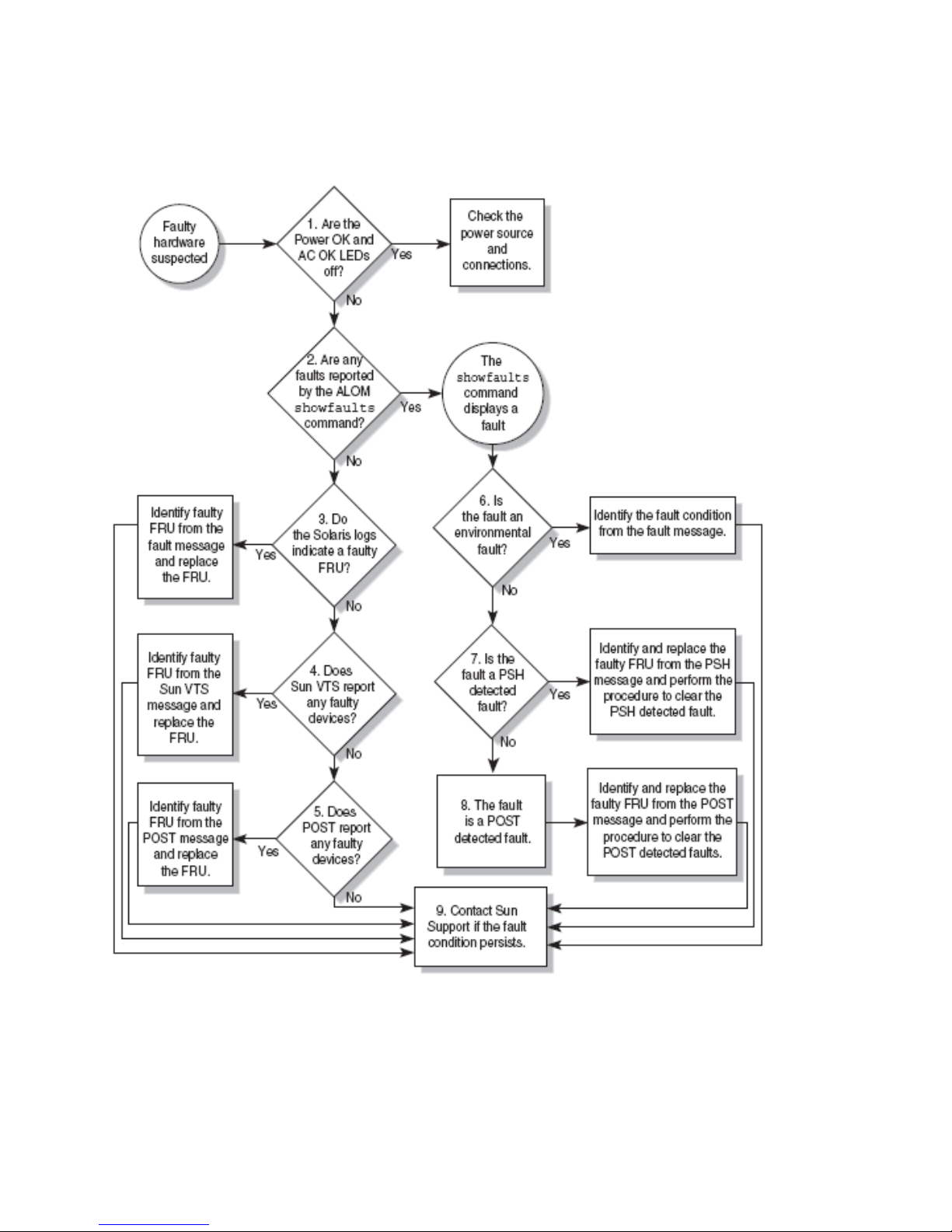
FIGURE 1-1 Diagnostic Flowchart
1-4 Sun Netra T5220 Server Service Manual • January 2012

TABLE 1-1 Diagnostic Flowchart Actions
Action
No. Diagnostic Action Resulting Action Additional Information
1.
2.
3.
4.
Check Power OK
and Input OK
LEDs on the server.
The Power OK LED is located on the front and rear
of the chassis.
The Input OK LED is located on the rear of the
server on each power supply.
If these LEDs are not on, check the power source and
power connections to the server.
Run the ALOM
CMT CLI
showfaults
command to check
for faults.
The showfaults command displays the following
kinds of faults:
• Environmental faults
• Solaris Predictive Self-Healing (PSH) detected
faults
• POST detected faults
Faulty FRUs are identified in fault messages using
the FRU name. For a list of FRU names, see
TABLE 2-1.
Check the Solaris
log files for fault
information.
The Solaris message buffer and log files record
system events and provide information about faults.
• If system messages indicate a faulty device,
replace the FRU.
• To obtain more diagnostic information, go to
Action
4.
Run SunVTS. SunVTS is an application you can run to exercise
and diagnose FRUs. To run SunVTS, the server must
be running the Solaris OS.
• If SunVTS reports a faulty device replace the FRU.
• If SunVTS does not report a faulty device, go to
Action
5.
Section 1.3, “Using LEDs to
Identify the State of
Devices” on page 1-8
Section 1.4.4, “Displaying
System Faults” on
page 1-21
Section 1.7, “Collecting
Information From Solaris
OS Files and Commands”
on page 1-42
Section 1.9, “Exercising the
System With SunVTS
Software” on page 1-46
5.
Run POST. POST performs basic tests of the server components
and reports faulty FRUs.
• If POST indicates a faulty FRU, replace the FRU.
• If POST does not indicate a faulty FRU, go to
Section 1.5, “Running
POST” on page 1-27
Action 9.
Chapter 1 Server Diagnostics 1-5

TABLE 1-1 Diagnostic Flowchart Actions (Continued)
Action
No. Diagnostic Action Resulting Action Additional Information
6.
7.
Determine if the
fault is an
environmental
fault.
Determine if the
fault was detected
by PSH.
If the fault listed by the showfaults command
displays a temperature or voltage fault, then the
fault is an environmental fault. Environmental faults
can be caused by faulty FRUs (power supply, fan, or
blower), or by environmental conditions such as
when computer room ambient temperature is too
high, or the server airflow is blocked. When the
environmental condition is corrected, the fault will
automatically clear.
If the fault indicates that a fan, blower, or power
supply is bad, you can perform a hot-swap of the
FRU. You can also use the fault LEDs on the server
to identify the faulty FRU (fans, blower, and power
supplies).
If the fault message displays the following text, the
fault was detected by the Solaris Predictive
Self-Healing software:
Host detected fault
If the fault is a PSH detected fault, identify the faulty
FRU from the fault message and replace the faulty
FRU.
After replacing the FRU, perform the procedure to
clear PSH detected faults.
Section 1.4.4, “Displaying
System Faults” on
page 1-21
Section 1.3, “Using LEDs to
Identify the State of
Devices” on page 1-8
Section 1.6, “Using the
Solaris Predictive
Self-Healing Feature” on
page 1-37
Section 1.6.2, “Clearing
PSH Detected Faults” on
page 1-40
8.
Determine if the
fault was detected
by POST.
POST performs basic tests of the server components
and reports faulty FRUs. When POST detects a
faulty FRU, it logs the fault and if possible, takes the
FRU offline. POST detected FRUs display the
following text in the fault message:
Section 1.5, “Running
POST” on page 1-27
FRU-name deemed faulty and disabled
In this case, replace the FRU and run the procedure
to clear POST detected faults.
Section 1.5.5, “Clearing
POST Detected Faults” on
page 1-35
1.2.1 Memory Configuration and Fault Handling
A variety of features play a role in how the memory subsystem is configured and
how memory faults are handled. Understanding the underlying features helps you
identify and repair memory problems. This section describes how the memory is
configured and how the server deals with memory faults.
1-6 Sun Netra T5220 Server Service Manual • January 2012

1.2.1.1 Memory Configuration
In the server memory there are 16 slots that hold DDR-2 memory FB-DIMMs in the
following FB-DIMM sizes:
■ 1 Gbyte (maximum of 16 Gbyte)
■ 2 Gbyte (maximum of 32 Gbyte)
■ 4 Gbyte (maximum of 64 Gbyte)
FB-DIMMs are installed in groups of 8, called ranks (ranks 0 and 1). At minimum,
rank 0 must be fully populated with eight FB-DIMMs of the same capacity. A second
rank of FB-DIMMs of the same capacity can be added to fill rank 1.
See Section 4.6, “Replacing FB-DIMMs” on page 4-23 for instructions about adding
memory to a server.
1.2.1.2 Memory Fault Handling
The server uses an advanced ECC technology, called chipkill, that corrects up to 4 bits
in error on nibble boundaries, as long as all of the bits are in the same DRAM. If a
DRAM fails, the FB-DIMM continues to function.
The following server features independently manage memory faults:
■ POST – Based on ILOM configuration variables, POST runs when the server is
powered on.
For correctable memory errors (CEs), POST forwards the error to the Solaris
Predictive Self-Healing (PSH) daemon for error handling. If an uncorrectable
memory fault is detected or if a “storm” of CEs is detected, POST displays the
fault with the device name of the faulty FB-DIMMs, logs the fault, and disables the
faulty FB-DIMMs by placing them in the ASR blacklist. Depending on the memory
configuration and the location of the faulty FB-DIMM, POST disables half of
physical memory in the system, or half the physical memory and half the
processor threads. When this offlining process occurs in normal operation, you
must replace the faulty FB-DIMMs based on the fault message. You then must
enable the disabled FB-DIMMs with the ALOM CMT CLI enablecomponent
command.
■ Solaris Predictive Self-Healing (PSH) technology – A feature of the Solaris OS,
uses the fault manager daemon (fmd) to watch for various kinds of faults. When a
fault occurs, the fault is assigned a unique fault ID (UUID), and logged. PSH
reports the fault and provides a recommended proactive replacement for the
FB-DIMMs associated with the fault.
Chapter 1 Server Diagnostics 1-7

1.2.1.3 Troubleshooting Memory Faults
If you suspect that the server has a memory problem, follow the flowchart
(
FIGURE 1-1). Run the ALOM CMT compatability CLI (in ILOM) showfaults
command, see Section 1.4.1, “Using the ALOM CMT Compatibility CLI in ILOM” on
page 1-16 and Section 1.4.4, “Displaying System Faults” on page 1-21. The
showfaults command lists memory faults and lists the specific FB-DIMMS that are
associated with the fault. Once you identify which FB-DIMMs to replace, see
Section 4.6, “Replacing FB-DIMMs” on page 4-23 for FB-DIMM replacement
instructions. You must perform the instructions in that chapter to clear the faults and
enable the replaced FB-DIMMs.
1.3 Using LEDs to Identify the State of
Devices
The server provides the following groups of LEDs:
■ Section 1.3.1, “Front and Rear Panel LEDs” on page 1-8
■ Section 1.3.2, “Hard Drive LEDs” on page 1-12
■ Section 1.3.3, “Power Supply LEDs” on page 1-12
■ Section 1.3.4, “Ethernet Port LEDs” on page 1-13
These LEDs provide a quick visual check of the state of the system.
1.3.1 Front and Rear Panel LEDs
The seven front panel LEDs (FIGURE 1-2) are located in the upper left corner of the
server chassis. Three of these LEDs are also provided on the rear panel (
FIGURE 1-3).
1-8 Sun Netra T5220 Server Service Manual • January 2012

FIGURE 1-2 Location of the Bezel Server Status and Alarm Status Indicators
5 6 7 8
4
3
2
1
Figure Legend
1 User (amber) Alarm Status Indicator 5 Locator LED and Button
2 Minor (amber) Alarm Status Indicator 6 Fault LED
3 Major (red) Alarm Status Indicator 7 Activity LED
4 Critical (red) Alarm Status Indicator 8 PowerOKLED
Chapter 1 Server Diagnostics 1-9

FIGURE 1-3 Rear Panel Connectors, LEDs, and Features on the Sun Netra T5220 Server
15 16 19
2 4 5
31 9
Figure Legend
1 Power Supply 0 LEDs top to bottom: Locator LED and
Button, Service Required LED, Power OK LED
2 Power Supply 0 12 USB ports left to right: USB0, USB1
3 Power Supply 1 LEDs top to bottom: Locator LED
Button, Service Required LED, Power OK LED
4 Power Supply 1 14 Captive screw for securing motherboard (2 of 2)
7 8
6
17 18
10
11 Alarm Port
13 TTYA Serial Port
11 14
12 13
20
5 Captive screw for securing motherboard (1 of 2) 15 PCI-X Slot 3
6 System LEDs left to right: Locator LED Button, Service
Required LED, Power OK LED
7 Service Processor Serial Management Port 17 PCI-X Slot 4
8 Service Processor Network Management Port 18 PCIe or XAUI Slot 1
9 Captive screws for securing the bottom PCI cards. Note
that there are two screws on either side of each bottom
PCI card (total 6).
10 Gigabit Ethernet Ports left to right: NET0, NET1, NET2,
NET3
16 PCIe or XAUI Slot 0
19 PCIe Slot 5
20 PCIe Slot 2
1-10 Sun Netra T5220 Server Service Manual • January 2012

TABLE 1-2 lists and describes the front and rear panel LEDs.
TABLE 1-2 Front and Rear Panel LEDs
LED Location Color Description
Locator LED
and Button
Front upper
left and rear
center
Fault LED Front upper
left and rear
center
Activity LED Front upper
left
Power Button Front upper
left
Alarm:Critical
Front left Red Indicates a critical alarm. Refer to the server administration guide
LED
Alarm:Major
Front left Red Indicates a major alarm.
LED
White Enables you to identify a particular server. The LED is activated
using one of the following methods:
• Issuing the setlocator on or off command.
• Pressing the button to toggle the indicator on or off.
This LED provides the following indications:
• Off – Normal operating state.
• Fast blink – The server received a signal as a result of one of the
preceding methods.
Amber If on, indicates that service is required. The ALOM CMT CLI
showfaults command provides details about any faults that cause
this indicator to be lit.
Green • On – Drives are receiving power. Solidly lit if drive is idle.
• Flashing – Drives are processing a command.
• Off – Power is off.
Turns the host system on and off. This button is recessed to prevent
accidental server power-off. Use the tip of a pen to operate this
button.
for a description of alarm states.
Alarm:Minor
Front left Amber Indicates a minor alarm.
LED
Alarm :User
Front left Amber Indicates a user alarm.
LED
Power OK LED Rear center Green The LED provides the following indications:
• Off – The system is unavailable. Either the system has no power
or ILOM is not running.
• Steady on – Indicates that the system is powered on and is
running it its normal operating state.
• Standby blink – Indicates that the service processor is running
while the system is running at a minimum level in Standby
mode, and is ready to be returned to its normal operating state.
• Slow blink – Indicates that a normal transitory activity is taking
place. The system diagnostics might be running, or that the
system might be booting.
Chapter 1 Server Diagnostics 1-11
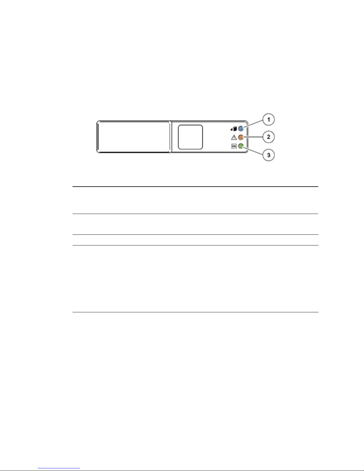
1.3.2 Hard Drive LEDs
The hard drive LEDs (FIGURE 1-4 and TABLE 1-3) are located on the front of each hard
drive that is installed in the server chassis.
FIGURE 1-4 Hard Drive LEDs
Figure Legend
1 OK to Remove
2 Fault
3 Activity
TABLE 1-3 Hard Drive LEDs
LED Color Description
OK to
Remove
Fault Amber • On – The drive has a fault and requires attention.
Activity Green • On – The drive is receiving power. Solidly lit if drive is idle.
Blue • On – The drive is ready for hot-plug removal.
• Off – Normal operation.
• Off – Normal operation.
• Flashing – The drive is processing a command.
• Off – Power is off.
1.3.3 Power Supply LEDs
The power supply LEDs (FIGURE 1-5 and TABLE 1-4) are located on the rear of each
power supply.
1-12 Sun Netra T5220 Server Service Manual • January 2012

FIGURE 1-5 Power Supply LEDs
1
2
3
Figure Legend
1 Power OK power supply LED
2 Fault power supply LED
3 Input OK power supply LED
TABLE 1-4 Power Supply LEDs
LED Color Description
Power OK
Fault Amber • On – Power supply has detected a failure.
Input OK Green • On – Normal operation. Input power is within normal limits.
Green • On – Normal operation. DC output voltage is within normal
limits.
• Off – Power is off.
• Off – Normal operation.
• Off – No input voltage, or input voltage is below limits.
1.3.4 Ethernet Port LEDs
The ILOM management Ethernet port and the four 10/100/1000 Mbps Ethernet ports
each have two LEDs, as shown in
FIGURE 1-6 and described in TABLE 1-5.
Chapter 1 Server Diagnostics 1-13

FIGURE 1-6 Ethernet Port LEDs
Figure Legend
1 Link/Activity indicator LED (Same location for all Ethernet ports)
2 Speed indicator LED (Same location for all Ethernet ports)
TABLE 1-5 Ethernet Port LEDs
LED Color Description
Left LED Green Link/Activity indicator:
• Steady On – a link is established.
• Blinking – there is activity on this port.
• Off – No link is established.
Right LED Amber
or
Green
Speed indicator:
• Amber On – The link is operating as a Gigabit connection
(1000-Mbps)
• Green On – The link is operating as a 100-Mbps connection.
• Off – The link is operating as a 10/100-Mbps connection.
Note – The NET MGT port operates only in 100-Mbps or 10-Mbps so the speed
indicator LED can be green or off (never amber).
1.4 Using the Service Processor Firmware for
Diagnosis and Repair Verification
The Sun Integrated Lights Out Manager (ILOM) firmware is a service processor in
the server that enables you to remotely manage and administer your server.
ILOM enables you to remotely run diagnostics, such as power-on self-test (POST),
that would otherwise require physical proximity to the server’s serial port. You can
also configure ILOM to send email alerts of hardware failures, hardware warnings,
and other events related to the server or to ILOM.
1-14 Sun Netra T5220 Server Service Manual • January 2012

The service processor runs independently of the server, using the server’s standby
power. Therefore, ILOM firmware and software continue to function when the server
operating system goes offline or when the server is powered off.
Note – ILOM provides an ALOM CMT compatibility CLI. Refer to the Sun Integrated
Lights Out Management 2.0 Supplement for the Sun Netra T5220 Server for
comprehensive ILOM and ALOM CMT compatibility information.
Faults detected by ILOM, POST, and the Solaris Predictive Self-Healing (PSH)
technology are forwarded to ILOM for fault handling (
FIGURE 1-7).
In the event of a system fault, ILOM ensures that the fault LED is lit, FRU ID PROMs
are updated, the fault is logged, and alerts are displayed (faulty FRUs are identified
in fault messages using the FRU name). For a list of FRU names, see
FIGURE 1-7 ILOM Fault Management
TABLE 2-1.
The service processor detects when a fault is no longer present and clears the fault in
several ways:
■ Fault recovery – The system automatically detects that the fault condition is no
longer present. ILOM extinguishes the Service Required LED and updates the
FRU’s PROM, indicating that the fault is no longer present.
■ Fault repair – The fault has been repaired by human intervention. In most cases,
the service processor detects the repair and extinguishes the Service Required
LED. If the service processor does not perform these actions, you must perform
these tasks manually with the clearfault or enablecomponent commands.
The service processor also detects the removal of a FRU, in many cases even if the
FRU is removed while the service processor is powered off (that is, if the system
power cables are unplugged during service procedures). This situation enables ILOM
to know that a fault, diagnosed to a specific FRU, has been repaired.
Note – ILOM does not automatically detect hard drive replacement.
Chapter 1 Server Diagnostics 1-15

Many environmental faults can automatically recover. A temperature that is
exceeding a threshold might return to normal limits. An unplugged power supply
can be plugged in, and so on. Recovery of environmental faults is automatically
detected. Recovery events are reported using one of two forms:
■ fru at location is OK.
■ sensor at location is within normal range.
Environmental faults can be repaired through hot-removal of the faulty FRU. FRU
removal is automatically detected by the environmental monitoring, and all faults
associated with the removed FRU are cleared. The message for that case, and the alert
sent for all FRU removals is:
fru at location has been removed.
There is no ILOM command to manually repair an environmental fault.
The Solaris Predictive Self-Healing technology does not monitor the hard drive for
faults. As a result, the service processor does not recognize hard drive faults, and will
not light the fault LEDs on either the chassis or the hard drive itself. Use the Solaris
message files to view hard drive faults. See Section 1.7, “Collecting Information From
Solaris OS Files and Commands” on page 1-42.
1.4.1 Using the ALOM CMT Compatibility CLI in
ILOM
There are three methods of interacting with the service processor:
■ ILOM CLI (default)
■ ILOM browser interface (BI)
■ ALOM CMT compatibility CLI (ALOM CMT CLI in ILOM)
Note – The examples in this section use the ALOM CMT compatibility CLI.
The ALOM CMT CLI emulates the ALOM CMT interface supported on the previous
generation of CMT servers. Using the ALOM CMT CLI (with few exceptions) you
can use commands that resemble the ALOM CMT commands. The comparisons
between the ILOM CLI and The ALOM CMT compatibility CLI are described in the
Sun Integrated Lights Out Management 2.0 Supplement for the Sun Netra T5220 Server.
The service processor sends alerts to all ALOM CMT CLI users that are logged in,
sending the alert through email to a configured email address, and writing the event
to the ILOM event log.
1-16 Sun Netra T5220 Server Service Manual • January 2012

1.4.2 Creating an ALOM CMT CLI Shell
To create an ALOM CMT CLI, do the following:
1. Log in to the service processor with username: root.
When powered on, the service processor boots to the ILOM login prompt. The
factory default password is changeme.
SUNSPxxxxxxxxxxxx login: root
Password:
Waiting for daemons to initialize...
Daemons ready
Sun(TM) Integrated Lights Out Manager
Version 2.0.0.0
Copyright 2008 Sun Microsystems, Inc. All rights reserved.
Use is subject to license terms.
Warning: password is set to factory default.
2. Create a new user, set the account role to Administrator and the CLI mode to
alom.
-> create /SP/users/admin
Creating user...
Enter new password: ********
Enter new password again: ********
Created /SP/users/admin
-> set /SP/users/admin role=Administrator
Set 'role' to 'Administrator'
-> set /SP/users/admin cli_mode=alom
Set 'cli_mode' to 'alom'
Note – The asterisks in the example will not appear when you enter your password.
You can combine the create and set commands on a single line:
-> create /SP/users/admin role=Administrator cli_mode=alom
Creating user...
Enter new password: ********
Enter new password again: ********
Created /SP/users/admin
Chapter 1 Server Diagnostics 1-17

3. Log out of the root account after you have finished creating the new account.
-> exit
4. Log in to the ALOM CMT CLI (indicated by the sc> prompt) from the ILOM
login prompt.
SUNSPxxxxxxxxxxxx login: admin
Password:
Waiting for daemons to initialize...
Daemons ready
Sun(TM) Integrated Lights Out Manager
Version 2.0.0.0
Copyright 2008 Sun Microsystems, Inc. All rights reserved.
Use is subject to license terms.
sc>
Note – Multiple service processor accounts can be active concurrently. A user can be
logged in under one account using the ILOM CLI, and another account using the
ALOM CMT CLI.
1.4.3 Running ALOM CMT CLI Service-Related
Commands
This section describes commands commonly used for service-related activities.
1.4.3.1 Connecting to ALOM CMT CLI
Before you can run ALOM CMT CLI commands, you must connect to the service
processor in one of two ways:
■ Connect an ASCII terminal directly to the serial management port.
■ Use the ssh command to connect to the service processor through an Ethernet
connection on the network management port.
1-18 Sun Netra T5220 Server Service Manual • January 2012

Note – Refer to the Sun Integrated Lights Out Management 2.0 Supplement for the Sun
Netra T5220 Server for instructions on configuring and connecting to the service
processor.
1.4.3.2 Switching Between the System Console and Service Processor
■ To switch from the console output to the ALOM CMT CLI sc> prompt, type #.
(Hash-Period).
■ To switch from the sc> prompt to the console, type console.
1.4.3.3 Service-Related ALOM CMT CLI Commands
TABLE 1-6 describes the typical ALOM CMT CLI commands for servicing a server. For
descriptions of all ALOM CMT CLI commands, issue the help command or refer to
the Integrated Lights Out Management User’s Guide.
TABLE 1-6 Service-Related ALOM CMT CLI Commands
ALOM CMT Command Description
help [command] Displays a list of all ALOM CMT CLI commands with syntax and
descriptions. Specifying a command name as an option displays help for
that command.
break [-y][-c][-D] Takes the host server from the OS to either kmdb or OpenBoot PROM
(equivalent to a Stop-A), depending on the mode Solaris software was
booted.
• -y skips the confirmation question
• -c executes a console command after the break command completes
• -D forces a core dump of the Solaris OS
clearfault UUID Manually clears host-detected faults. The UUID is the unique fault ID of the
fault to be cleared.
console [-f] Connects you to the host system. The -f option forces the console to have
read and write capabilities.
consolehistory [-b lines|-e
lines|-v] [-g lines]
[boot|run]
Displays the contents of the system’s console buffer. The following options
enable you to specify how the output is displayed:
• -g lines specifies the number of lines to display before pausing.
• -e lines displays n lines from the end of the buffer.
• -b lines displays n lines from beginning of buffer.
• -v displays entire buffer.
• boot|run specifies the log to display (run is the default log).
Chapter 1 Server Diagnostics 1-19

TABLE 1-6 Service-Related ALOM CMT CLI Commands (Continued)
ALOM CMT Command Description
bootmode
[normal|reset_nvram|
bootscript=string]
Enables control of the firmware during system initialization with the
following options:
• normal is the default boot mode.
• reset_nvram resets OpenBoot PROM parameters to their default values.
• bootscript=string enables the passing of a string to the boot
command.
powercycle [-f] Performs a poweroff followed by poweron. The -f option forces an
immediate poweroff, otherwise the command attempts a graceful
shutdown.
poweroff [-y][-f] Powers off the host server. The -y option enables you to skip the
confirmation question. The -f option forces an immediate shutdown.
poweron [-c] Powers on the host server. Using the -c option executes a console
command after completion of the poweron command.
removefru PS0|PS1 Indicates if it is okay to perform a hot-swap of a power supply. This
command does not perform any action, but it provides a warning if the
power supply should not be removed because the other power supply is
not enabled.
reset [-y] [-c] Generates a hardware reset on the host server. The -y option enables you to
skip the confirmation question. The -c option executes a console
command after completion of the reset command.
resetsc [-y] Reboots the service processor. The -y option enables you to skip the
confirmation question.
setkeyswitch [-y] normal |
stby | diag | locked
Sets the virtual keyswitch. The -y option enables you to skip the
confirmation question when setting the keyswitch to stby.
setlocator [on | off] Turns the Locator LED on the server on or off.
showenvironment Displays the environmental status of the host server. This information
includes system temperatures, power supply, front panel LED, hard drive,
fan, voltage, and current sensor status. See Section 1.4.6, “Displaying the
Server’s Environmental Status” on page 1-23.
showfaults [
-v] Displays current system faults. See Section 1.4.4, “Displaying System
Faults” on page 1-21.
showfru [-g lines][-s | -d]
[FRU]
Displays information about the FRUs in the server.
• -g lines specifies the number of lines to display before pausing the output
to the screen.
• -s displays static information about system FRUs (defaults to all FRUs,
unless one is specified).
• -d displays dynamic information about system FRUs (defaults to all
FRUs, unless one is specified). See Section 1.4.7, “Displaying FRU
Information” on page 1-25.
1-20 Sun Netra T5220 Server Service Manual • January 2012

TABLE 1-6 Service-Related ALOM CMT CLI Commands (Continued)
ALOM CMT Command Description
showkeyswitch Displays the status of the virtual keyswitch.
showlocator Displays the current state of the Locator LED as either on or off.
showlogs [-b lines | -e lines |
-v] [-g lines][-p
logtype[r|p]]]
showplatform [-v] Displays information about the host system’s hardware configuration, the
Displays the history of all events logged in the ALOM CMT event buffers
(in RAM or the persistent buffers).
system serial number, and whether the hardware is providing service.
Note – See TABLE 1-10 for the ALOM CMT CLI automatic system recover (ASR)
commands.
1.4.4 Displaying System Faults
The ALOM CMT CLI showfaults command displays the following kinds of faults:
■ Environmental or configuration faults – System configuration faults, or
temperature or voltage problems that might be caused by faulty FRUs (power
supplies, fans, or blower), or by room temperature or blocked air flow to the
server.
■ POST detected faults – Faults on devices detected by the power-on self-test
diagnostics.
■ PSH detected faults – Faults detected by the Solaris Predictive Self-healing (PSH)
technology
Use the showfaults command for the following reasons:
■ To see if any faults have been diagnosed in the system.
■ To verify that the replacement of a FRU has cleared the fault and not generated
any additional faults.
● At the sc> prompt, type the showfaults command.
The following showfaults command examples show the different kinds of
output from the showfaults command:
Chapter 1 Server Diagnostics 1-21

■ Example of the showfaults command when no faults are present:
sc> showfaults
Last POST run: THU MAR 09 16:52:44 2006
POST status: Passed all devices
No failures found in System
■ Example of the showfaults command displaying an environmental fault:
sc> showfaults
Last POST Run: Wed Jul 18 11:44:47 2007
Post Status: Passed all devices
ID FRU Fault
0 /SYS/FANBD0/FM0 SP detected fault: TACH at /SYS/FANBD0/FM0/F1
has exceeded low non-recoverable threshold.
■ Example showing a fault that was detected by POST. These kinds of faults are
identified by the message Forced fail reason where reason is the name of the
power-on routine that detected the failure.
sc> showfaults
Last POST Run: Wed Jun 27 21:29:02 2007
Post Status: Passed all devices
ID FRU Fault
0 /SYS/MB/CMP0/BR3/CH1/D1 SP detected fault:
/SYS/MB/CMP0/BR3/CH1/D1 Forced fail (POST)
■ Example showing a fault that was detected by the PSH technology. These kinds
of faults are identified by the text
Host detected fault and by a UUID.
sc> showfaults -v
Last POST Run: Wed Jun 29 11:29:02 2007
Post Status: Passed all devices
ID Time FRU Fault
0 Jun 30 22:13:02 /SYS/MB Host detected fault, MSGID:
SUN4V-8000-N3 UUID: 7ee0e46b-ea64-6565-e684-e996963f7b86
1-22 Sun Netra T5220 Server Service Manual • January 2012

1.4.5 Manually Cleaning PSH Diagnosed Faults
The ALOM CMT CLI clearfault command enables you to manually clear PSH
diagnosed faults from the service processor without a FRU replacement or if the
service processor was unable to automatically detect the FRU replacement.
● At the sc> prompt, type the clearfault command.
■ Example showing a fault being cleared manually using the clearfault
command:
sc> clearfault 7ee0e46b-ea64-6565-e684-e996963f7b86
1.4.6 Displaying the Server’s Environmental Status
The showenvironment command displays a snapshot of the server ’s environmental
status. This command displays system temperatures, hard drive status, power supply
and fan status, front panel LED status, and voltage and current sensors. The output
uses a format similar to the Solaris OS command prtdiag (1m).
● At the sc> prompt, type the showenvironment command.
The output differs according to your system’s model and configuration.
Chapter 1 Server Diagnostics 1-23

EXAMPLE 1-1 shows abridged output of the showenvironment command.
EXAMPLE 1-1 showenvironment Command Output
sc> showenvironment
-----------------------------------------------------------------------------System Temperatures (Temperatures in Celsius):
-----------------------------------------------------------------------------Sensor Status Temp LowHard LowSoft LowWarn HighWarn
HighSoft HighHard
-----------------------------------------------------------------------------/SYS/MB/T_AMB OK 29 -10 -5 0 50 55 60
/SYS/MB/CMP0/T_TCORE OK 50 -14 -9 -4 86 96 106
/SYS/MB/CMP0/T_BCORE OK 51 -14 -9 -4 86 96 106
/SYS/MB/CMP0/BR0/CH0/D0/T_AMB OK 41 -10 -8 -5 95 100 105
...
-----------------------------------------------------------------------------System Indicator Status:
-----------------------------------------------------------------------------/SYS/LOCATE /SYS/SERVICE /SYS/ACT
OFF OFF ON
-----------------------------------------------------------------------------/SYS/PSU_FAULT /SYS/TEMP_FAULT /SYS/FAN_FAULT
OFF OFF OFF
-----------------------------------------------------------------------------System Disks:
-----------------------------------------------------------------------------Disk Status Service OK2RM
-----------------------------------------------------------------------------/SYS/HDD0 OK OFF OFF
/SYS/HDD1 NOT PRESENT OFF OFF
...
1-24 Sun Netra T5220 Server Service Manual • January 2012

EXAMPLE 1-1 showenvironment Command Output (Continued)
-----------------------------------------------------------------------------Fan Status:
-----------------------------------------------------------------------------Fans (Speeds Revolution Per Minute):
Sensor Status Speed Warn Low
-----------------------------------------------------------------------------/SYS/FANBD0/FM0/F0/TACH OK 7000 4000 2400
...
-----------------------------------------------------------------------------Voltage sensors (in Volts):
-----------------------------------------------------------------------------Sensor Status Voltage LowSoft LowWarn HighWarn HighSoft
-----------------------------------------------------------------------------/SYS/MB/V_+3V3_STBY OK 3.39 3.13 3.17 3.53 3.58
...
-----------------------------------------------------------------------------Power Supplies:
-----------------------------------------------------------------------------Supply Status Fan_Fault Temp_Fault Volt_Fault Cur_Fault
-----------------------------------------------------------------------------/SYS/PS0 OK OFF OFF OFF OFF
...
Note – Some environmental information might not be available when the server is in
standby mode.
1.4.7 Displaying FRU Information
The showfru command displays information about the FRUs in the server. Use this
command to see information about an individual FRU, or for all the FRUs.
Note – By default, the output of the showfru command for all FRUs is very long.
Chapter 1 Server Diagnostics 1-25

● At the sc> prompt, enter the showfru command.
In the following example, the showfru command is used to get information about
the motherboard (MB).
sc> showfru /SYS/MB
/SYS/MB (container)
SEGMENT: FL
/Configured_LevelR
/Configured_LevelR/UNIX_Timestamp32: Thu Jun 7 20:12:17 GMT
2007
/Configured_LevelR/Sun_Part_No: 5412153
/Configured_LevelR/Configured_Serial_No: BBX053
/Configured_LevelR/Initial_HW_Dash_Level: 02
SEGMENT: FD
/InstallationR (1 iterations)
/InstallationR[0]
/InstallationR[0]/UNIX_Timestamp32: Thu Jun 21 19:37:57 GMT
2007
/InstallationR[0]/Fru_Path: /SYS/MB
/InstallationR[0]/Parent_Part_Number: 5017813
/InstallationR[0]/Parent_Serial_Number: 110508
/InstallationR[0]/Parent_Dash_Level: 01
/InstallationR[0]/System_Id: 0721BBB050
/InstallationR[0]/System_Tz: 0
...
1-26 Sun Netra T5220 Server Service Manual • January 2012

1.5 Running POST
Power-on self-test (POST) is a group of PROM-based tests that run when the server is
powered on or reset. POST checks the basic integrity of the critical hardware
components in the server (CPU, memory, and I/O buses).
If POST detects a faulty component, the component is disabled automatically,
preventing faulty hardware from potentially harming any software. If the system is
capable of running without the disabled component, the system will boot when
POST is complete. For example, if one of the processor cores is deemed faulty by
POST, the core will be disabled, and the system will boot and run using the
remaining cores.
1.5.1 Controlling How POST Runs
The server can be configured for normal, extensive, or no POST execution. You can
also control the level of tests that run, the amount of POST output that is displayed,
and which reset events trigger POST by using ALOM CMT CLI variables.
TABLE 1-7 lists the ALOM CMT CLI variables used to configure POST. FIGURE 1-8
shows how the variables work together.
Note – Use the ALOM CMT CLI setsc command to set all the parameters in
TABLE 1-7 except setkeyswitch.
TABLE 1-7 ALOM CMT CLI Parameters Used for POST Configuration
Parameter Values Description
setkeyswitch normal The system can power on and run POST (based
on the other parameter settings). For details see
FIGURE 1-8. This parameter overrides all other
commands.
diag The system runs POST based on predetermined
settings.
stby The system cannot power on.
locked The system can power on and run POST, but no
flash updates can be made.
diag_mode off POST does not run.
normal Runs POST according to diag_level value.
Chapter 1 Server Diagnostics 1-27

TABLE 1-7 ALOM CMT CLI Parameters Used for POST Configuration (Continued)
Parameter Values Description
service Runs POST with preset values for diag_level
and diag_verbosity.
diag_level max If diag_mode = normal, runs all the minimum
tests plus extensive CPU and memory tests.
min If diag_mode = normal, runs minimum set of
tests.
diag_trigger none Does not run POST on reset.
user_reset Runs POST upon user-initiated resets.
power_on_reset Only runs POST for the first power on. This
option is the default.
error_reset Runs POST if fatal errors are detected.
all_resets Runs POST after any reset.
diag_verbosity none No POST output is displayed.
min POST output displays functional tests with a
banner and pinwheel.
normal POST output displays all test and informational
messages.
max POST displays all test, informational, and some
debugging messages.
1-28 Sun Netra T5220 Server Service Manual • January 2012

FIGURE 1-8 Flowchart of ALOM CMT CLI Variables for POST Configuration
Chapter 1 Server Diagnostics 1-29

TABLE 1-8 shows typical combinations of ALOM CMT CLI variables and associated
POST modes.
TABLE 1-8 ALOM CMT CLI Parameters and POST Modes
Parameter
Normal Diagnostic Mode
(Default Settings) No POST Execution
Diagnostic Service
Mode
Keyswitch Diagnostic
Preset Values
diag_mode normal off service normal
setkeyswitch
*
normal normal normal diag
diag_level max n/a max max
diag_trigger power-on-reset
none all-resets all-resets
error-reset
diag_verbosity normal n/a max max
Description of POST
execution
* The setkeyswitch parameter, when set to diag, overrides all the other ALOM CMT CLI POST variables.
This is the default POST
configuration. This
configuration tests the
system thoroughly, and
suppresses some of the
detailed POST output.
POST does not
run, resulting in
quick system
initialization. This
is not a suggested
configuration.
POST runs the full
spectrum of tests
with the maximum
output displayed.
POST runs the full
spectrum of tests
with the maximum
output displayed.
1.5.2 Changing POST Parameters
1. Access the ALOM CMT CLI sc> prompt:
At the console, issue the #. key sequence:
#.
2. Use the ALOM CMT CLI sc> prompt to change the POST parameters.
Refer to
TABLE 1-7 for a list of ALOM CMT CLI POST parameters and their values.
The setkeyswitch parameter sets the virtual keyswitch, so this parameter does
not use the setsc command. For example, to change the POST parameters using
the setkeyswitch command, enter the following:
sc> setkeyswitch diag
1-30 Sun Netra T5220 Server Service Manual • January 2012

To change the POST parameters using the setsc command, you must first set the
setkeyswitch parameter to normal. Then you can change the POST parameters
using the setsc command:
sc> setkeyswitch normal
sc> setsc value
For example:
sc> setkeyswitch normal
sc> setsc diag_mode service
1.5.3 Reasons to Run POST
You can use POST for basic hardware verification and diagnosis, and for
troubleshooting as described in the following sections.
1.5.3.1 Verifying Hardware Functionality
POST tests critical hardware components to verify functionality before the system
boots and accesses software. If POST detects an error, the faulty component is
disabled automatically, preventing faulty hardware from potentially harming
software.
1.5.3.2 Diagnosing the System Hardware
You can use POST as an initial diagnostic tool for the system hardware. In this case,
configure POST to run in maximum mode (diag_mode=service, setkeyswitch=
diag, diag_level=max) for thorough test coverage and verbose output.
1.5.4 Running POST in Maximum Mode
This procedure describes how to run POST when you want maximum testing, as in
the case when you are troubleshooting a server or verifying a hardware upgrade or
repair.
Chapter 1 Server Diagnostics 1-31

1. Switch from the system console prompt to the sc> prompt by issuing the #.
escape sequence.
ok #.
sc>
2. Set the virtual keyswitch to diag so that POST will run in service mode.
sc> setkeyswitch diag
3. Reset the system so that POST runs.
There are several ways to initiate a reset.
EXAMPLE 1-2 shows the powercycle
command. For other methods, refer to the Sun Netra T5220 Server Administration
Guide.
EXAMPLE 1-2 Initiating POST Using the powercycle Command
sc> powercycle
Are you sure you want to powercycle the system (y/n)? y
Powering host off at Fri Jul 27 08:11:52 2007
Waiting for host to Power Off; hit any key to abort.
Audit | minor: admin : Set : object = /SYS/power_state : value =
soft : success
Chassis | critical: Host has been powered off
Powering host on at Fri Jul 27 08:13:08 2007
Audit | minor: admin : Set : object = /SYS/power_state : value =
on : success
Chassis | major: Host has been powered on
1-32 Sun Netra T5220 Server Service Manual • January 2012

4. Switch to the system console to view the POST output:
sc> console
EXAMPLE 1-3 depicts abridged POST output.
EXAMPLE 1-3 POST Output (Abridged)
sc> console
Enter #. to return to ALOM.
2007-07-03 10:25:12.081 0:0:0>@(#)Sun Netra[TM] T5220 POST 4.x.build_119
2007/06/06 09:48
/export/delivery/delivery/4.x/4.x.build_119/post4.x/UltraSPARC/NetraT5220/inte
grated (root)
2007-07-03 10:25:12.386 0:0:0>Copyright 2007 Sun Microsystems, Inc. All rights
reserved
2007-07-03 10:25:12.550 0:0:0>VBSC cmp0 arg is: 00ff00ff.ffffffff
2007-07-03 10:25:12.653 0:0:0>POST enabling threads: 00ff00ff.ffffffff
2007-07-03 10:25:12.766 0:0:0>VBSC mode is: 00000000.00000001
2007-07-03 10:25:12.867 0:0:0>VBSC level is: 00000000.00000001
2007-07-03 10:25:12.966 0:0:0>VBSC selecting POST MAX Testing.
2007-07-03 10:25:13.066 0:0:0>VBSC setting verbosity level 3
2007-07-03 10:25:13.161 0:0:0>UltraSPARCT2, Version 2.1
2007-07-03 10:25:13.247 0:0:0>Serial Number: 0fac006b.0e654482
2007-07-03 10:25:13.353 0:0:0>Basic Memory Tests.....
2007-07-03 10:25:13.456 0:0:0>Begin: Branch Sanity Check
2007-07-03 10:25:13.569 0:0:0>End : Branch Sanity Check
2007-07-03 10:25:13.668 0:0:0>Begin: DRAM Memory BIST
2007-07-03 10:25:13.793
0:0:0>........................................................................
........................
2007-07-03 10:25:38.399 0:0:0>End : DRAM Memory BIST
2007-07-03 10:25:39.547 0:0:0>Sys 166 MHz, CPU 1166 MHz, Mem 332 MHz
2007-07-03 10:25:39.658 0:0:0>L2 Bank EFuse = 00000000.000000ff
2007-07-03 10:25:39.760 0:0:0>L2 Bank status = 00000000.00000f0f
2007-07-03 10:25:39.864 0:0:0>Core available Efuse = ffff00ff.ffffffff
2007-07-03 10:25:39.982 0:0:0>Test Memory.....
2007-07-03 10:25:40.070 0:0:0>Begin: Probe and Setup Memory
2007-07-03 10:25:40.181 0:0:0>INFO: 4096MB at Memory Branch 0
...
2007-07-03 10:29:21.683 0:0:0>INFO:
2007-07-03 10:29:21.686 0:0:0>POST Passed all devices.
2007-07-03 10:29:21.692 0:0:0>POST:Return to VBSC.
5. Perform further investigation if needed.
■ If no faults were detected, the system will boot.
Chapter 1 Server Diagnostics 1-33

■ If POST detects a faulty device, the fault is displayed and the fault information is
passed to ALOM CMT CLI for fault handling. Faulty FRUs are identified in fault
messages using the FRU name. For a list of FRU names, see
TABLE 2-1.
a. Interpret the POST messages:
POST error messages use the following syntax:
c:s > ERROR: TEST = failing-test
c:s > H/W under test = FRU
c:s > Repair Instructions: Replace items in order listed by
H/W under test above
c:s > MSG = test-error-message
c:s > END_ERROR
In this syntax, c = the core number, s = the strand number.
Warning and informational messages use the following syntax:
INFO or WARNING: message
In
EXAMPLE 1-4, POST reports a memory error at FB-DIMM location
/SYS/MB/CMP0/BR2/CH0/D0. The error was detected by POST running on core
7, strand 2.
EXAMPLE 1-4 POST Error Message
7:2>
7:2>ERROR: TEST = Data Bitwalk
7:2>H/W under test = /SYS/MB/CMP0/BR2/CH0/D0
7:2>Repair Instructions: Replace items in order listed by 'H/W
under test' above.
7:2>MSG = Pin 149 failed on /SYS/MB/CMP0/BR2/CH0/D0 (J2001)
7:2>END_ERROR
7:2>Decode of Dram Error Log Reg Channel 2 bits
60000000.0000108c
7:2> 1 MEC 62 R/W1C Multiple corrected
errors, one or more CE not logged
7:2> 1 DAC 61 R/W1C Set to 1 if the error
was a DRAM access CE
7:2> 108c SYND 15:0 RW ECC syndrome.
7:2>
7:2> Dram Error AFAR channel 2 = 00000000.00000000
7:2> L2 AFAR channel 2 = 00000000.00000000
1-34 Sun Netra T5220 Server Service Manual • January 2012

b. Run the showfaults command to obtain additional fault information.
The fault is captured by ALOM CMT CLI, where the fault is logged, the Service
Required LED is lit, and the faulty component is disabled.
Example:
EXAMPLE 1-5 showfaults Output
ok .#
sc> showfaults
Last POST Run: Wed Jun 27 21:29:02 2007
Post Status: Passed all devices
ID FRU Fault
0 /SYS/MB/CMP0/BR2/CH0/D0 SP detected fault: /SYS/MB/CMP0/BR2/CH0/D0
Forced fail (POST)
In this example, /SYS/MB/CMP0/BR2/CH0/D0 is disabled. The system can boot
using memory that was not disabled until the faulty component is replaced.
Note – You can use ASR commands to display and control disabled components. See
Section 1.8, “Managing Components With Automatic System Recovery Commands”
on page 1-43.
1.5.5 Clearing POST Detected Faults
In most cases, when POST detects a faulty component, POST logs the fault and
automatically takes the failed component out of operation by placing the component
in the ASR blacklist (see Section 1.8, “Managing Components With Automatic System
Recovery Commands” on page 1-43).
In most cases, the replacement of the faulty FRU is detected when the service
processor is reset or power cycled. In this case, the fault is automatically cleared from
the system. This procedure describes how to identify POST detected faults and, if
necessary, manually clear the fault.
Chapter 1 Server Diagnostics 1-35

1. After replacing a faulty FRU, at the ALOM CMT CLI prompt use the
showfaults command to identify POST detected faults.
POST detected faults are distinguished from other kinds of faults by the text:
Forced fail, and no UUID number is reported.
Example:
EXAMPLE 1-6 POST Detected Fault
sc> showfaults
Last POST Run: Wed Jun 27 21:29:02 2007
Post Status: Passed all devices
ID FRU Fault
0 /SYS/MB/CMP0/BR2/CH0/D0 SP detected fault: /SYS/MB/CMP0/BR2/CH0/D0 Forced
fail (POST)
If no fault is reported, you do not need to do anything else. Do not perform the
subsequent steps.
2. Use the enablecomponent command to clear the fault and remove the
component from the ASR blacklist.
Use the FRU name that was reported in the fault in Step 1.
EXAMPLE 1-7 Using the enablecomponent Command
sc> enablecomponent /SYS/MB/CMP0/BR2/CH0/D0
The fault is cleared and should not show up when you run the showfaults
command. Additionally, the Service Required LED is no longer on.
3. Power cycle the server.
You must reboot the server for the enablecomponent command to take effect.
4. At the ALOM CMT CLI prompt, use the showfaults command to verify that
no faults are reported.
TABLE 1-9 Verifying Cleared Faults Using the showfaults Command
sc> showfaults
Last POST run: THU MAR 09 16:52:44 2006
POST status: Passed all devices
No failures found in System
1-36 Sun Netra T5220 Server Service Manual • January 2012

1.6 Using the Solaris Predictive Self-Healing
Feature
The Solaris Predictive Self-Healing (PSH) technology enables the server to diagnose
problems while the Solaris OS is running, and mitigate many problems before they
negatively affect operations.
The Solaris OS uses the fault manager daemon, fmd(1M), which starts at boot time
and runs in the background to monitor the system. If a component generates an error,
the daemon handles the error by correlating the error with data from previous errors
and other related information to diagnose the problem. Once diagnosed, the fault
manager daemon assigns the problem a Universal Unique Identifier (UUID) that
distinguishes the problem across any set of systems. When possible, the fault
manager daemon initiates steps to self-heal the failed component and take the
component offline. The daemon also logs the fault to the syslogd daemon and
provides a fault notification with a message ID (MSGID). You can use the message ID
to get additional information about the problem from Sun’s knowledge article
database.
The Predictive Self-Healing technology covers the following server components:
■ UltraSPARC® T2 multicore processor
■ Memory
■ I/O bus
The PSH console message provides the following information:
■ Type
■ Severity
■ Description
■ Automated response
■ Impact
■ Suggested action for system administrator
If the Solaris PSH facility detects a faulty component, use the fmdump command to
identify the fault. Faulty FRUs are identified in fault messages using the FRU name.
For a list of FRU names, see
TABLE 2-1.
Chapter 1 Server Diagnostics 1-37

1.6.1 Identifying PSH Detected Faults
When a PSH fault is detected, a Solaris console message similar to EXAMPLE 1-8 is
displayed.
EXAMPLE 1-8 Console Message Showing Fault Detected by PSH
SUNW-MSG-ID: SUN4V-8000-DX, TYPE: Fault, VER: 1, SEVERITY: Minor
EVENT-TIME: Wed Sep 14 10:09:46 EDT 2005
PLATFORM: SUNW,Sun-Netra-T5220, CSN: -, HOSTNAME: hostname
SOURCE: cpumem-diagnosis, REV: 1.5
EVENT-ID: f92e9fbe-735e-c218-cf87-9e1720a28004
DESC: The number of errors associated with this memory module has exceeded
acceptable levels.
AUTO-RESPONSE: Pages of memory associated with this memory module are being
removed from service as errors are reported.
IMPACT: Total system memory capacity will be reduced as pages are retired.
REC-ACTION: Schedule a repair procedure to replace the affected memory module.
Use fmdump -v -u <EVENT_ID> to identify the module.
Faults detected by the Solaris PSH facility are also reported through service processor
alerts.
Solaris PSH in
EXAMPLE 1-9 depicts an ALOM CMT CLI alert of the same fault reported by
EXAMPLE 1-8.
EXAMPLE 1-9 ALOM CMT CLI Alert of PSH Diagnosed Fault
SC Alert: Host detected fault, MSGID: SUN4V-8000-DX
The ALOM CMT CLI showfaults command provides summary information about
the fault. See Section 1.4.4, “Displaying System Faults” on page 1-21 for more
information about the showfaults command.
Note – The Service Required LED is also turns on for PSH diagnosed faults.
1.6.1.1 Using the fmdump Command to Identify Faults
The fmdump command displays the list of faults detected by the Solaris PSH facility
and identifies the faulty FRU for a particular EVENT_ID (UUID).
Do not use fmdump to verify a FRU replacement has cleared a fault because the
output of fmdump is the same after the FRU has been replaced. Use the fmadm
faulty command to verify the fault has cleared.
1-38 Sun Netra T5220 Server Service Manual • January 2012

1. Check the event log using the fmdump command with -v for verbose output:
EXAMPLE 1-10 Output from the fmdump -v Command
# fmdump -v -u fd940ac2-d21e-c94a-f258-f8a9bb69d05b
TIME UUID SUNW-MSG-ID
Jul 31 12:47:42.2007 fd940ac2-d21e-c94a-f258-f8a9bb69d05b SUN4V-8000-JA
100% fault.cpu.ultraSPARC-T2.misc_regs
Problem in: cpu:///cpuid=16/serial=5D67334847
Affects: cpu:///cpuid=16/serial=5D67334847
FRU: hc://:serial=101083:part=541215101/motherboard=0
Location: MB
In
EXAMPLE 1-10, a fault is displayed, indicating the following details:
■ Date and time of the fault (Jul 31 12:47:42.2007)
■ Universal Unique Identifier (UUID). This is unique for every fault
(
fd940ac2-d21e-c94a-f258-f8a9bb69d05b)
■ Sun message identifier, which can be used to obtain additional fault information
(SUN4V-8000-JA)
■ Faulted FRU. The information provided in the example includes the part number
of the FRU (part=541215101) and the serial number of the FRU (serial=
101083). The Location field provides the name of the FRU. In
EXAMPLE 1-10 the
FRU name is MB, meaning the motherboard.
Note – fmdump displays the PSH event log. Entries remain in the log after the fault
has been repaired.
2. Use the Sun message ID to obtain more information about this type of fault.
a. Obtain the message ID from the console output or the ALOM CMT CLI
showfaults command.
Chapter 1 Server Diagnostics 1-39

b. Enter the message ID in the SUNW-MSG-ID field, and click Lookup.
EXAMPLE 1-11, the message ID SUN4V-8000-JA provides information for
In
corrective action:
EXAMPLE 1-11 PSH Message Output
CPU errors exceeded acceptable levels
Type
Fault
Severity
Major
Description
The number of errors associated with this CPU has exceeded
acceptable levels.
Automated Response
The fault manager will attempt to remove the affected CPU from
service.
Impact
System performance may be affected.
Suggested Action for System Administrator
Schedule a repair procedure to replace the affected CPU, the
identity of which can be determined using fmdump -v -u <EVENT_ID>.
Details
The Message ID: SUN4V-8000-JA indicates diagnosis has
determined that a CPU is faulty. The Solaris fault manager arranged
an automated attempt to disable this CPU. The recommended action
for the system administrator is to contact Sun support so a Sun
service technician can replace the affected component.
3. Follow the suggested actions to repair the fault.
1.6.2 Clearing PSH Detected Faults
When the Solaris PSH facility detects faults the faults are logged and displayed on
the console. In most cases, after the fault is repaired, the corrected state is detected
by the system and the fault condition is repaired automatically. However, this
must be verified and, in cases where the fault condition is not automatically
cleared, the fault must be cleared manually.
1. After replacing a faulty FRU, power on the server.
1-40 Sun Netra T5220 Server Service Manual • January 2012

2. At the ALOM CMT CLI prompt, use the showfaults command to identify PSH
detected faults.
PSH detected faults are distinguished from other kinds of faults by the text:
Host detected fault.
Example:
sc> showfaults -v
Last POST Run: Wed Jun 29 11:29:02 2007
Post Status: Passed all devices
ID Time FRU Fault
0 Jun 30 22:13:02 /SYS/MB/CMP0/BR2/CH0/D0 Host detected fault,
MSGID: SUN4V-8000-DX UUID: 7ee0e46b-ea64-6565-e684-e996963f7b86
■ If no fault is reported, you do not need to do anything else. Do not perform the
subsequent steps.
■ If a fault is reported, perform Step 3 and Step 4.
3. Run the ALOM CMT CLI clearfault command with the UUID provided in
the showfaults output.
Example:
sc> clearfault 7ee0e46b-ea64-6565-e684-e996963f7b86
Clearing fault from all indicted FRUs...
Fault cleared.
4. Clear the fault from all persistent fault records.
In some cases, even though the fault is cleared, some persistent fault information
remains and results in erroneous fault messages at boot time. To ensure that these
messages are not displayed, perform the following Solaris command:
fmadm repair UUID
Example:
# fmadm repair 7ee0e46b-ea64-6565-e684-e996963f7b86
Chapter 1 Server Diagnostics 1-41

1.7 Collecting Information From Solaris OS
Files and Commands
With the Solaris OS running on the server, you have the full complement of Solaris
OS files and commands available for collecting information and for troubleshooting.
If POST, service processor, or the Solaris PSH features do not indicate the source of a
fault, check the message buffer and log files for notifications for faults. Hard drive
faults are usually captured by the Solaris message files.
Use the dmesg command to view the most recent system message. To view the
system messages log file, view the contents of the /var/adm/messages file.
1.7.1 Checking the Message Buffer
1. Log in as superuser.
2. Type the dmesg command:
# dmesg
The dmesg command displays the most recent messages generated by the system.
1.7.2 Viewing System Message Log Files
The error logging daemon, syslogd, automatically records various system warnings,
errors, and faults in message files. These messages can alert you to system problems
such as a device that is about to fail.
The /var/adm directory contains several message files. The most recent messages
are in the /var/adm/messages file. After a period of time (usually every ten days),
a new messages file is automatically created. The original contents of the messages
file are rotated to a file named messages.1. Over a period of time, the messages are
further rotated to messages.2 and messages.3, and then deleted.
1. Log in as superuser.
2. Type the following command:
# more /var/adm/messages
1-42 Sun Netra T5220 Server Service Manual • January 2012

3. If you want to view all logged messages, type the following command:
# more /var/adm/messages*
1.8 Managing Components With Automatic
System Recovery Commands
The Automatic System Recovery (ASR) feature enables the server to automatically
configure failed components out of operation until they can be replaced. In the
server, theASR feature manages the following components:
■ UltraSPARC T2 processor strands
■ Memory FB-DIMMs
■ I/O bus
The database that contains the list of disabled components is called the ASR blacklist
(asr-db).
In most cases, POST automatically disables a faulty component. After the cause of the
fault is repaired (FRU replacement, loose connector reseated, and so on), you must
remove the component from the ASR blacklist.
The ASR commands (
TABLE 1-10) enable you to view, and manually add or remove
components from the ASR blacklist. You run these commands from the ALOM CMT
CLI sc> prompt.
TABLE 1-10 ASR Commands
Command Description
showcomponent Displays system components and their current state.
enablecomponent asrkey Removes a component from the asr-db blacklist,
where asrkey is the component to enable.
disablecomponent asrkey Adds a component to the asr-db blacklist, where
asrkey is the component to disable.
clearasrdb Removes all entries from the asr-db blacklist.
Note – The components (asrkeys) vary from system to system, depending on how
many cores and memory are present. Use the showcomponent command to see the
asrkeys on a given system.
Chapter 1 Server Diagnostics 1-43

Note – A reset or power cycle is required after disabling or enabling a component. If
the status of a component is changed, there is no effect to the system until the next
reset or power cycle.
1.8.1 Displaying System Components
The showcomponent command displays the system components (asrkeys) and
reports their status.
● At the sc> prompt, enter the showcomponent command
EXAMPLE 1-12 shows partial output with no disabled components.
EXAMPLE 1-12 Output of the showcomponent Command With No Disabled Components
sc> showcomponent
Keys:
/SYS/MB/RISER0/XAUI0
/SYS/MB/RISER0/PCIE0
/SYS/MB/RISER0/PCIE3
/SYS/MB/RISER1/XAUI1
/SYS/MB/RISER1/PCIE1
/SYS/MB/RISER1/PCIE4
/SYS/MB/RISER2/PCIE2
/SYS/MB/RISER2/PCIE5
/SYS/MB/GBE0
/SYS/MB/GBE1
/SYS/MB/PCIE
/SYS/MB/PCIE-IO/USB
/SYS/MB/SASHBA
/SYS/MB/CMP0/NIU0
/SYS/MB/CMP0/NIU1
/SYS/MB/CMP0/MCU0
/SYS/MB/CMP0/MCU1
/SYS/MB/CMP0/MCU2
/SYS/MB/CMP0/MCU3
1-44 Sun Netra T5220 Server Service Manual • January 2012

EXAMPLE 1-12 Output of the showcomponent Command With No Disabled Components
/SYS/MB/CMP0/L2_BANK0
/SYS/MB/CMP0/L2_BANK1
/SYS/MB/CMP0/L2_BANK2
/SYS/MB/CMP0/L2_BANK3
/SYS/MB/CMP0/L2_BANK4
/SYS/MB/CMP0/L2_BANK5
/SYS/MB/CMP0/L2_BANK6
/SYS/MB/CMP0/L2_BANK7
...
/SYS/TTYA
State: Clean
EXAMPLE 1-13 shows showcomponent command output with a component disabled:
EXAMPLE 1-13 Output of the showcomponent Command Showing Disabled Components
sc> showcomponent
Keys:
/SYS/MB/RISER0/XAUI0
/SYS/MB/RISER0/PCIE0
/SYS/MB/RISER0/PCIE3
/SYS/MB/RISER1/XAUI1
/SYS/MB/RISER1/PCIE1
/SYS/MB/RISER1/PCIE4
/SYS/MB/RISER2/PCIE2
/SYS/MB/RISER2/PCIE5
...
/SYS/TTYA
Disabled Devices
/SYS/MB/CMP0/L2_BANK0Disabled by user
1.8.2 Disabling Components
The disablecomponent command disables a component by adding it to the ASR
blacklist.
1. At the sc> prompt, enter the disablecomponent command
sc> disablecomponent /SYS/MB/CMP0/BR1/CH0/D0
Chassis | major: /SYS/MB/CMP0/BR1/CH0/D0 has been disabled.
Disabled by user
.
Chapter 1 Server Diagnostics 1-45

2. After receiving confirmation that the disablecomponent command is
complete, reset the server so that the ASR command takes effect.
sc> reset
1.8.3 Enabling Disabled Components
The enablecomponent command enables a disabled component by removing it
from the ASR blacklist.
1. At the sc> prompt, enter the enablecomponent command.
sc> enablecomponent /SYS/MB/CMP0/BR1/CH0/D0
Chassis | major: /SYS/MB/CMP0/BR1/CH0/D0 has been enabled.
2. After receiving confirmation that the enablecomponent command is complete,
reset the server for so that the ASR command takes effect.
sc> reset
1.9 Exercising the System With SunVTS
Software
Sometimes a server exhibits a problem that cannot be isolated definitively to a
particular hardware or software component. In such cases, it might be useful to run a
diagnostic tool that stresses the system by continuously running a comprehensive
battery of tests. Sun provides the SunVTS software for this purpose.
This section describes the tasks necessary to use SunVTS software to exercise your
server:
■ Section 1.9.1, “Checking Whether SunVTS Software Is Installed” on page 1-46
■ Section 1.9.2, “Exercising the System Using SunVTS Software” on page 1-47
1.9.1 Checking Whether SunVTS Software Is Installed
This procedure assumes that the Solaris OS is running on the server, and that you
have access to the Solaris command line.
1-46 Sun Netra T5220 Server Service Manual • January 2012

1. Check for the presence of SunVTS packages using the pkginfo command.
% pkginfo -l SUNWvts SUNWvtsr SUNWvtsts SUNWvtsmn
TABLE 1-11 lists SunVTS packages:
TABLE 1-11 SunVTS Packages
Package Description
SUNWvts SunVTS framework
SUNWvtsr SunVTS framework (root)
SUNWvtsts SunVTS for tests
SUNWvtsmn SunVTS man pages
■ If SunVTS software is installed, information about the packages is displayed.
■ If SunVTS software is not installed, you see an error message for each missing
package, as in
EXAMPLE 1-14 Missing Package Errors for SunVTS
EXAMPLE 1-14
ERROR: information for "SUNWvts" was not found
ERROR: information for "SUNWvtsr" was not found
...
The SunVTS 6.0 PS3 software, and future compatible versions, are supported on the
server.
SunVTS installation instructions are described in the SunVTS User’s Guide.
1.9.2 Exercising the System Using SunVTS Software
Before you begin, the Solaris OS must be running. You also must ensure that SunVTS
validation test software is installed on your system. See Section 1.9.1, “Checking
Whether SunVTS Software Is Installed” on page 1-46.
The SunVTS installation process requires that you specify one of two security
schemes to use when running SunVTS. The security scheme you choose must be
properly configured in the Solaris OS for you to run SunVTS. For details, refer to the
SunVTS User’s Guide.
Chapter 1 Server Diagnostics 1-47

SunVTS software features both character-based and graphics-based interfaces. This
procedure assumes that you are using the graphical user interface (GUI) on a system
running the Common Desktop Environment (CDE). For more information about the
character-based SunVTS TTY interface, and specifically for instructions on accessing
it by tip or telnet commands, refer to the SunVTS User’s Guide.
SunVTS software can be run in several modes. This procedure assumes that you are
using the default mode.
This procedure also assumes that the server is headless. That is, it is not equipped
with a monitor capable of displaying bitmap graphics. In this case, you access the
SunVTS GUI by logging in remotely from a machine that has a graphics display.
Finally, this procedure describes how to run SunVTS tests in general. Individual tests
might presume the presence of specific hardware, or might require specific drivers,
cables, or loopback connectors. For information about test options and prerequisites,
refer to the following documentation:
■ SunVTS 6.3 Test Reference Manual for SPARC Platforms
■ SunVTS 6.3 User’s Guide
1.9.3 Exercising the System With SunVTS Software
1. Log in as superuser to a system with a graphics display.
The display system should be one with a frame buffer and monitor capable of
displaying bitmap graphics such as those produced by the SunVTS GUI.
2. Enable the remote display.
On the display system, type:
# /usr/openwin/bin/xhost + test-system
where test-system is the name of the server you plan to test.
3. Remotely log in to the server as superuser.
Use a command such as rlogin or telnet.
1-48 Sun Netra T5220 Server Service Manual • January 2012

4. Start SunVTS software.
If you have installed SunVTS software in a location other than the default /opt
directory, alter the path, as in
EXAMPLE 1-15 Alternate Command for Starting SunVTS Software
EXAMPLE 1-15.
# /opt/SUNWvts/bin/sunvts -display display-system:0
where display-system is the name of the machine through which you are remotely
logged in to the server.
The SunVTS GUI is displayed (
FIGURE 1-9 SunVTS GUI
FIGURE 1-9).
5. Expand the test lists to see the individual tests.
The test selection area lists tests in categories, such as Network, as shown in
FIGURE 1-10. To expand a category, left-click the icon (expand category icon) to
the left of the category name.
+
Chapter 1 Server Diagnostics 1-49

FIGURE 1-10 SunVTS Test Selection Panel
6. (Optional) Select the tests you want to run.
Certain tests are enabled by default, and you can choose to accept these.
Alternatively, you can enable and disable individual tests or blocks of tests by
clicking the checkbox next to the test name or test category name. Tests are
enabled when checked, and disabled when not checked.
TABLE 1-12 lists tests that are especially useful to run on this server.
TABLE 1-12 Useful SunVTS Tests to Run on This Server
SunVTS Tests FRUs Exercised by Tests
cmttest, cputest, fputest,
iutest, l1dcachetest, dtlbtest,
and l2sramtest – indirectly: mptest,
and systest
disktest Disks, cables, disk backplane
cddvdtest CD/DVD device, cable, motherboard
nettest, netlbtest Network interface, network cable, CPU
pmemtest, vmemtest, ramtest FB-DIMMs, motherboard
serialtest I/O (serial port interface)
usbkbtest, disktest USB devices, cable, CPU motherboard (USB
hsclbtest Motherboard, service processor
FB-DIMMS, CPU motherboard
motherboard
controller)
(Host to service processor interface)
7. (Optional) Customize individual tests.
You can customize individual tests by right-clicking on the name of the test. For
example, in FIGURE 1-10, right-clicking on the text string ce0(nettest) brings up
a menu that enables you to configure this Ethernet test.
1-50 Sun Netra T5220 Server Service Manual • January 2012

8. Start testing.
Click the Start button that is located at the top left of the SunVTS window. Status
and error messages appear in the test messages area located across the bottom of
the window. You can stop testing at any time by clicking the Stop button.
During testing, SunVTS software logs all status and error messages. To view these
messages, click the Log button or select Log Files from the Reports menu. This
action opens a log window from which you can choose to view the following logs:
■ Information – Detailed versions of all the status and error messages that appear in
the test messages area.
■ Test Error – Detailed error messages from individual tests.
■ VTS Kernel Error – Error messages pertaining to SunVTS software itself. Look
here if SunVTS software appears to be acting strangely, especially when it starts
up.
■ Solaris OS Messages (/var/adm/messages) – A file containing messages
generated by the operating system and various applications.
■ Log Files (/var/opt/SUNWvts/logs) – A directory containing the log files.
1.10 Obtaining the Chassis Serial Number
To obtain support for your system, you need your chassis serial number. The chassis
serial number is located on a sticker that is on the front of the server and another
sticker on the side of the server. You can also run the ALOM CMT CLI
showplatform command to obtain the chassis serial number.
For example:
TABLE 1-13 Obtaining the Chassis Serial Number With the showplatform Command
sc> showplatform
SUNW,Sun-Netra-T5220
Chassis Serial Number: xxxxxxxxxxxx
Domain Status
------ -----S0 OS Standby
sc>
Chapter 1 Server Diagnostics 1-51

1.11 Additional Service Related Information
In addition to this service manual, the following resources are available to help you
keep your server running optimally. These documents are available at:
http://www.oracle.com/technetwork/indexes/documentation/index.ht
ml
■ Server Product Notes – Contain late-breaking information about the system
including required software patches, updated hardware and compatibility
information, and solutions to know issues.
■ Solaris Release Notes – Contain important information about the Solaris OS.
1-52 Sun Netra T5220 Server Service Manual • January 2012

CHAPTER
2
Preparing for Service
This chapter describes safety considerations and provides prerequisite procedures
and information to replace components within the server.
Topics include:
■ Section 2.1, “Safety Information” on page 2-1
■ Section 2.2, “Required Tools” on page 2-3
■ Section 2.3, “Prerequisite Tasks for Component Replacement” on page 2-3
■ Section 2.4, “Field-Replaceable Units” on page 2-11
2.1 Safety Information
This section describes important safety information you need to know prior to
removing or installing parts in the server.
For your protection, observe the following safety precautions when setting up your
equipment:
■ Follow all Sun standard cautions, warnings, and instructions marked on the
equipment and described in Important Safety Information for Sun Hardware Systems,
816-7190.
■ Ensure that the voltage and frequency of your power source match the voltage and
frequency inscribed on the equipment s electrical rating label.
■ Follow the electrostatic discharge safety practices as described in this section.
2.1.1 Safety Symbols
The following symbols might appear in this book, note their meanings:
2-1

Caution – There is a risk of personal injury and equipment damage. To avoid
personal injury and equipment damage, follow the instructions.
Caution – Hot surface. Avoid contact. Surfaces are hot and might cause personal
injury if touched.
Caution – Hazardous voltages are present. To reduce the risk of electric shock and
danger to personal health, follow the instructions.
2.1.2 Electrostatic Discharge Safety
Electrostatic discharge (ESD) sensitive devices, such as the motherboard, PCI cards,
hard drives, and memory cards require special handling.
Caution – The boards and hard drives contain electronic components that are
extremely sensitive to static electricity. Ordinary amounts of static electricity from
clothing or the work environment can destroy components. Do not touch the
components along their connector edges.
2.1.2.1 Use an Antistatic Wrist Strap
Wear an antistatic wrist strap and use an antistatic mat when handling components
such as drive assemblies, boards, or cards. When servicing or removing server
components, attach an antistatic strap to your wrist and then to a metal area on the
chassis. Then disconnect the power cords from the server. Following this practice
equalizes the electrical potentials between you and the server.
2.1.2.2 Use an Antistatic Mat
Place ESD-sensitive components such as the motherboard, memory, and other PCB
cards on an antistatic mat.
2-2 Sun Netra T5220 Server Service Manual • January 2012

2.2 Required Tools
The server can be serviced with the following tools:
■ Antistatic wrist strap
■ Antistatic mat
■ No. 2 Phillips screwdriver
2.3 Prerequisite Tasks for Component
Replacement
Before you can remove and install components that are inside the server, you must
perform the following procedures:
■ Section 2.3.1, “Powering Off the Server” on page 2-3
■ Section 2.3.2, “Disconnecting Cables From the Server” on page 2-4
■ Section 2.3.3, “Removing the Server From the Rack” on page 2-5
■ Section 2.3.4, “Performing Antistatic Measures” on page 2-8
■ Section 2.3.5, “Removing the Top Cover” on page 2-8
Depending upon the component, you might also need to remove the PCI tray:
■ Section 2.3.6, “Removing the PCI Mezzanine” on page 2-9
Note – When replacing the hard drives or power supplies, not all of these tasks are
necessary. The replacement procedures for those components address this fact.
2.3.1 Powering Off the Server
Performing a graceful shutdown makes sure all of your data is saved and the system
is ready for restart.
1. Log in as superuser or equivalent.
Depending on the nature of the problem, you might want to view the system
status, the log files, or run diagnostics before you shut down the system. Refer to
the server administration guide for log file information.
Chapter 2 Preparing for Service 2-3

2. Notify affected users.
Refer to your Solaris system administration documentation for additional
information.
3. Save any open files and quit all running programs.
Refer to your application documentation for specific information on these
processes.
4. Shut down the Solaris OS.
Refer to the Solaris system administration documentation for additional
information.
5. Switch from the system console to the ALOM CMT compatibility CLI sc>
prompt by typing the #. (Hash-Period) key sequence.
6. At the ALOM CMT compatibility CLI sc> prompt, issue the poweroff
command.
sc> poweroff -fy
SC Alert: SC Request to Power Off Host Immediately.
Note – You can also use the Power button on the front of the server to initiate a
graceful system shutdown. This button is recessed to prevent accidental server
power-off. Use the tip of a pen to operate this button.
Refer to the Integrated Lights Out Manager (ILOM) Administration Guide for more
information about the ALOM CMT CLI poweroff command.
7. Disconnect the cables from the server.
See Section 2.3.2, “Disconnecting Cables From the Server” on page 2-4.
2.3.2 Disconnecting Cables From the Server
Caution – The system supplies standby power to the circuit boards even when the
system is powered off.
1. Label all cables connected to the server.
2. Disconnect the following cables as appropriate:
■ PCI-X 3
■ PCI-X 4
2-4 Sun Netra T5220 Server Service Manual • January 2012

■ PCIe 5
■ PCIe 2
■ PCIe 1/XAUI 1
■ PCIe 0/XAUI 0
■ Alarm
■ TTYA
■ SER MGT
■ NET MGT
■ USB 0
■ USB 1
■ NET 0
■ NET 1
■ NET 2
■ NET 3
■ Power supply 0
■ Power supply 1
3. If you are going to remove the CMA, also remove the cables from it.
4. Remove the server from the rack.
2.3.3 Removing the Server From the Rack
Remove the server from the rack prior to performing cold-swappable FRU
replacement procedures except the FB-DIMMs, PCI cards, and the service
processor.
Caution – The server weighs approximately 40 lb (18 kg). Two people are required
to dismount and carry the chassis.
1. Disconnect all the cables and power cords from the server.
2. From the front of the server, release the slide rail latches on each side.
Pinch the green latches as shown in
FIGURE 2-1.
Chapter 2 Preparing for Service 2-5

FIGURE 2-1 Slide Release Latches
3. While pinching the release latches, slowly pull the server forward until the
slide rails latch.
4. Press the metal lever (
FIGURE 2-2) that is located on the inner side of the rail to
disconnect the CMA from the rail assembly (on the right side from the rear of
the rack).
The CMA is still attached to the cabinet, but the server chassis is now
disconnected from the CMA.
2-6 Sun Netra T5220 Server Service Manual • January 2012

FIGURE 2-2 Locating the Metal Lever
Caution – The server weighs approximately 40 lb (18 kg). The next step requires two
people to dismount and carry the chassis.
5. From the front of the server, pull the release tabs forward and pull the server
forward until it is free of the rack rails.
The release tabs are located on each rail, about midway on the server.
6. Set the server on a sturdy work surface.
7. Perform antistatic measures.
See Section 2.3.4, “Performing Antistatic Measures” on page 2-8.
Chapter 2 Preparing for Service 2-7

2.3.4 Performing Antistatic Measures
1. Prepare an antistatic surface on which to set parts during removal and
installation.
Place ESD-sensitive components such as the printed circuit boards on an antistatic
mat. The following items can be used as an antistatic mat:
■ Antistatic bag used to wrap a Sun replacement part
■ Sun ESD mat, part number 250-1088
■ Disposable ESD mat (shipped with some replacement parts or optional system
components)
2. Attach an antistatic wrist strap.
When servicing or removing server components, attach an antistatic strap to your
wrist and then to a metal area on the chassis. Then disconnect the power cords
from the server.
3. Remove the top cover.
See Section 2.3.5, “Removing the Top Cover” on page 2-8.
2.3.5 Removing the Top Cover
All field-replaceable units (FRUs) that are not hot-swappable require the removal of
the top cover.
1. Use a No. 2 Philips screwdriver to press the top cover release button (
FIGURE 2-3 Top Cover and Release Button
1
FIGURE 2-3).
2
2-8 Sun Netra T5220 Server Service Manual • January 2012

Figure Legend
1 To p c ov er
2 Top cover release button
2. While pressing the top cover release button, slide the cover toward the rear of
the server.
3. Lift the cover off the chassis and set it aside.
4. If necessary, remove the PCI mezzanine.
See Section 2.3.6, “Removing the PCI Mezzanine” on page 2-9.
2.3.6 Removing the PCI Mezzanine
The PCI mezzanine is a carrier for the PCI-X and PCIe cards. Remove the PCI
mezzanine to replace the following components:
■ PCIe card
■ LED board
■ FB-DIMM/CPU duct
■ Alarm board
■ FB-DIMMs
■ Motherboard assembly
■ Power distribution board (PDB)
It is not necessary to remove the PCI mezzanine for other components. However,
when the PCI mezzanine is removed, additional working space is provided.
1. Disconnect any I/0 cables from the rear of the PCI mezzanine.
2. Disconnect the PCI mezzanine cable (
FIGURE 2-5).
Chapter 2 Preparing for Service 2-9

FIGURE 2-4 Removing the PCI Mezzanine Cable and I/O Cables From PCI Mezzanine
3. Use a No. 2 Philips Screwdriver to loosen the four green captive screws securing
the PCI mezzanine. (
FIGURE 2-5).
4. Lift the PCI mezzanine up and out. (
FIGURE 2-5).
2-10 Sun Netra T5220 Server Service Manual • January 2012

FIGURE 2-5 Removing Screws and Lifting the PCI Mezzanine
5. Lift the PCI mezzanine away from the chassis and place it on an antistatic mat.
You are now ready to replace components.
2.4 Field-Replaceable Units
FIGURE 2-6 and TABLE 2-1 identifies the field-replaceable units (FRUS) in the server.
Chapter 2 Preparing for Service 2-11

FIGURE 2-6 Field-Replaceable Units
1
17
19
18
2
16
15
3
14
4
5
6
2-12 Sun Netra T5220 Server Service Manual • January 2012
87
9
10 11
12
13

TABLE 2-1 Server FRU List
No. FRU Replacement Instructions Description FRU Name
1
Top Cover Section 2.3.5, “Removing the
Top Cover” on page 2-8
2
FB-DIMM/CPU
duct
3
System Fan
Assembly
Section 4.4, “Replacing the
Air Duct” on page 4-17
Section 5.3, “Replacing the
System Fan Assembly
Requires a pen to remove. Does not power
off server when removed.
Aids cooling of FB-DIMMS and CPU.
Contains three fans for cooling the motherboard assembly.
FT0
(FT0)” on page 5-6
4
FB-DIMM Fan Section 5.5, “Replacing the
Single fan for cooling FB-DIMMs
FB-DIMM Fan Assembly
(FT2)” on page 5-14
5
LED board Section 5.7, “Replacing the
LED Board” on page 5-17
Contains the push-button circuitry and
LEDs that are displayed on the bezel of
LEDBD
the box.
6
Air filter Section 5.1, “Replacing the
Cleans air before entering system.
Air Filter” on page 5-1
7
Media bay
assembly
Section 3.3, “Replacing the
Media Bay Assembly” on
Bays that house hard drives and optical
media drive.
page 3-8
8
Optical media
drive
Section 3.2, “Replacing the
Optical Media Drive” on
Optical media drive DVD
page 3-6
*
9
Hard drives Section 3.1, “Replacing a
Hard Drive” on page 3-1
10
Power
distribution
board (PDB)
11
Alarm board Section 5.6, “Replacing the
Section n, “Section 6.1.6,
“Powering On the Server”
on page 6-8” on page 5-22
Alarm Board” on page 5-15
12
Hard drive fan
assembly
Section 5.4, “Replacing the
Hard Drive Fan Assembly
(FT1)” on page 5-9
13
Power supplies
(PS)
Section 5.2, “Replacing a
Power Supply” on page 5-3
SAS, 2.5-inch 146 GB hard drives
The two HDD configuration includes a
removable DVD drive; the four HDD has
HDD2 and HDD3 in place of the DVD.
Provides the main 12V power interconnect
between the power supplies and the other
boards.
Provides dry-contact switching according
to alarm conditions.
Fans that provide supplemental cooling of
the hard drives and optical media drive.
The 650W power supplies provide -3.3
Vdc standby power at 3 @ 3 Amps and 12
Vdc at 25 Amps.
Chapter 2 Preparing for Service 2-13
HDD0
HDD1
HDD2 HDD3
PDB
PS0
PS1

TABLE 2-1
Server FRU List (Continued)
No. FRU Replacement Instructions Description FRU Name
14
Motherboard
assembly
Section 4.10, “Replacing the
Motherboard Assembly” on
Must be removed before removing the
power distribution board.
MB
page 4-36
15
PCI riser
assembly
Section 4.2.4, “Replacing the
Lower PCIe/XAUI Cards”
Houses and connects the bottom PCI cards
on page 4-11
16
PCI mezzanine Section 2.3.6, “Removing the
Houses and connects the top PCI cards PCI_MEZZ
PCI Mezzanine” on page 2-9
17
PCI-X cards Section 4.2.2, “Replacing
PCI-X 4 and PCIe 5 Cards”
Optional add-on cards PCI-X4
PCI-X3
on page 4-5
18
PCIe cards Section 4.2.4, “Replacing the
Lower PCIe/XAUI Cards”
on page 4-11
19
FB-DIMMs Section 4.6, “Replacing
FB-DIMMs” on page 4-23
Optional add-on cards PCIE0/XAUI0
PCIE1/XAUI1
PCIE2, PCIE5
Can be ordered in the following sizes:
• 1 GB (16 GB maximum)
• 2 GB (32 GB maximum)
See
FIGURE 4-15
and TABLE 4-1
• 4 GB (64 GB maximum)
*
* The FRU name is used in system messages.
2-14 Sun Netra T5220 Server Service Manual • January 2012

CHAPTER
3
Replacing Storage Components
This chapter provides instructions for replacing nonvolatile data storage components.
Topics include:
■ Section 3.1, “Replacing a Hard Drive” on page 3-1
■ Section 3.2, “Replacing the Optical Media Drive” on page 3-6
■ Section 3.3, “Replacing the Media Bay Assembly” on page 3-8
3.1 Replacing a Hard Drive
The hard drives in the server are hot-pluggable, but this capability depends on how
the hard drives are configured. To hot-plug a drive you must be able to take the drive
offline before you can remove it. Prevent any applications from accessing the drive
and remove the logical software links to it.
The following situations inhibit the ability to perform hot-plugging of a drive:
■ The hard drive provides the operating system, and the operating system is not
mirrored on another drive.
■ The hard drive cannot be logically isolated from the online operations of the
server.
If your drive falls into one of these conditions, you must shut the system down
before you replace the hard drive. See Section 2.3.1, “Powering Off the Server” on
page 2-3.
Note – Replacing a hard drive does not require removing the server from a rack.
3-1

3.1.1 Removing a Hard Drive
1. Press the green tabs on either side of the bezel and pull forward and down
(
FIGURE 3-1).
FIGURE 3-1 Opening the Bezel
2. Identify the location of the hard drive that you want to remove (FIGURE 3-2 and
FIGURE 3-3).
3-2 Sun Netra T5220 Server Service Manual • January 2012

FIGURE 3-2 Locations of HDDs on 2 HDD Server
1 2
Figure Legend
1 Hard Drive 1 (HDD1)
2 Hard Drive 0 (HDD0)
FIGURE 3-3 Locations of HDDs on 4 HDD Server
1 2
Figure Legend
1 Hard Drive 2 (HDD2)
2 Hard Drive 3 (HDD3)
3 Hard Drive 1 (HDD1)
4 Hard Drive 0 (HDD0)
3 4
3. Type the Solaris OS commands required to stop using the hard drive.
Exact commands required depend on the configuration of your hard drives. You
might need to unmount file systems or perform RAID commands.
4. On the drive you plan to remove, push the latch release button (
FIGURE 3-4).
The latch opens.
Chapter 3 Replacing Storage Components 3-3
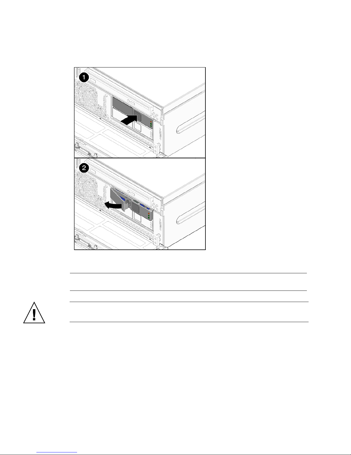
FIGURE 3-4 Opening Hard Drive Latch
Figure Legend
1 Latch release button
2 Latch
Caution – The latch is not an ejector. Do not bend it too far to the left. Doing so can
damage the latch.
5. Grasp the latch and pull the drive out of the drive slot (
3-4 Sun Netra T5220 Server Service Manual • January 2012
FIGURE 3-5).

FIGURE 3-5 Removing Hard Drive
6. Consider your next steps:
■ If you are replacing the hard drive, continue to Section 3.1.2, “Installing a Hard
Drive” on page 3-5.
■ If you are not replacing the hard drive, perform administrative tasks to configure
the server to operate without the hard drive.
3.1.2 Installing a Hard Drive
1. Remove the replacement hard drive from its packaging and place it on an
antistatic mat.
2. Align the replacement drive to the drive slot.
The hard drive is physically addressed according to the slot in which it is
installed. It is important to install a replacement drive in the same slot as the drive
that was removed.
3. Slide the drive into the bay until it is fully seated (
FIGURE 3-6).
Chapter 3 Replacing Storage Components 3-5

FIGURE 3-6 Installing the Hard Drive
4. Close the latch to lock the drive in place.
5. Close the bezel.
6. Perform administrative tasks to reconfigure the hard drive.
The procedures that you perform at this point depend on how your data is
configured. You might need to partition the drive, create file systems, load data
from backups, or have it updated from a RAID configuration.
3.2 Replacing the Optical Media Drive
3.2.1 Removing the Optical Media Drive
1. Prepare the server for media bay assembly removal. See:
■ Section 2.3.1, “Powering Off the Server” on page 2-3
■ Section 2.3.4, “Performing Antistatic Measures” on page 2-8
2. Open the bezel.
3. Push the release tab to the left and pull the probe forward, freeing the optical
media drive (
Note – You do not need to remove the top cover to remove the optical media drive.
The following illustration shows the top cover removed for clarity of placement.
3-6 Sun Netra T5220 Server Service Manual • January 2012
FIGURE 3-7).

FIGURE 3-7 Releasing the Optical Media Drive
4. Remove the optical media drive from the media bay assembly and set it aside
on an antistatic mat.
5. Consider your next step:
■ If you removed the optical media drive as part of another procedure, return to that
procedure.
■ Otherwise, continue to Section 3.2.2, “Installing the Optical Media Drive” on
page 3-7.
3.2.2 Installing the Optical Media Drive
1. Remove the replacement optical media drive from its packaging and place it on
an antistatic mat.
2. Hold the tab to the left and insert the optical media drive into the media bay
assembly (
Note – You do not need to install the top cover to remove the optical media drive.
The following illustration shows the top cover removed for clarity of placement.
FIGURE 3-8).
Chapter 3 Replacing Storage Components 3-7

FIGURE 3-8 Inserting the Optical Media Drive
3. Press the optical media drive in until it seats and release the tab.
4. Close the bezel.
5. Consider your next step:
■ If you installed the optical drive as part of another procedure, return to that
procedure.
■ Otherwise, perform the following tasks to bring the server back online:
■ Section 6.1.3, “Removing Antistatic Measures” on page 6-4
■ Section 6.1.6, “Powering On the Server” on page 6-8
3.3 Replacing the Media Bay Assembly
3.3.1 Removing the Media Bay Assembly
1. Prepare the server for media bay assembly removal. See:
■ Section 2.3.1, “Powering Off the Server” on page 2-3
■ Section 2.3.2, “Disconnecting Cables From the Server” on page 2-4
■ Section 2.3.3, “Removing the Server From the Rack” on page 2-5
■ Section 2.3.4, “Performing Antistatic Measures” on page 2-8
■ Section 2.3.5, “Removing the Top Cover” on page 2-8
2. Remove the optical media drive and the hard drives. See:
■ Section 3.2.1, “Removing the Optical Media Drive” on page 3-6
3-8 Sun Netra T5220 Server Service Manual • January 2012

■ Section 3.1.1, “Removing a Hard Drive” on page 3-2
3. Disconnect the following cables from the media bay assembly (
FIGURE 3-9):
a. (Optional) Disconnect the blue system fan tray assembly cable that connects
to the PDB underneath the media bay assembly cables (
FIGURE 3-9).
This step allows easier access to the media bay assembly cables.
b. Disconnect media bay assembly cable (top) that connects to the motherboard
(
FIGURE 3-9).
c. Disconnect media bay assembly cable (bottom) that connects to power
distribution board (PDB) (
FIGURE 3-9).
d. Disonnect media bay assembly ribbon cable that connects to the PDB
(
FIGURE 3-9).
You can disconnect this cable from the rear of the media bay assembly or from
the PDB after loosening the screws and lifting the assembly out of the chassis.
FIGURE 3-9 Media Bay Assembly Cables
Chapter 3 Replacing Storage Components 3-9

4. Loosen captive screws labeled 2 and 3, and remove non-captive screw labeled 1
closest to the front of the server (
FIGURE 3-10).
5. Lift the media bay assembly out of the chassis (
FIGURE 3-10 Loosening the Media Bay Assembly Screws and Lifting From Chassis
FIGURE 3-10).
6. (Optional) Disconnect and remove the ribbon cable from the PDB.
7. Set the media bay assembly aside on an antistatic mat.
8. Consider your next step:
■ If you removed the media bay assembly as part of another procedure, return to
that procedure.
■ Otherwise, continue to Section 3.3.2, “Installing the Media Bay Assembly” on
page 3-11.
3-10 Sun Netra T5220 Server Service Manual • January 2012

3.3.2 Installing the Media Bay Assembly
1. Remove the replacement media bay assembly from its packaging and place it on
an antistatic mat.
2. Move the cables as far out of the way as possible.
3. If disconnected, reconnect the media bay assembly ribbon cable to the PDB.
Arrange the cable where it can be reconnected to the assembly after it is reseated.
4. Lower the media bay assembly into the chassis until it seats (
5. Tighten the media bay assembly screws (
FIGURE 3-11 Setting the Media Bay Assembly Into Place and Tightening Screws
FIGURE 3-11).
FIGURE 3-11).
Chapter 3 Replacing Storage Components 3-11

6. Connect the following cables to the media bay assembly (FIGURE 3-12):
FIGURE 3-12 Connecting the Media Bay Assembly Cables
7. Install the optical media drive and the hard drives. See:
■ Section 3.2.2, “Installing the Optical Media Drive” on page 3-7
■ Section 3.1.2, “Installing a Hard Drive” on page 3-5
8. Close the bezel.
9. Consider your next step:
■ If you installed the media bay bracket as part of another procedure, return to that
procedure.
■ Otherwise, perform the following tasks to bring the server back online:
■ Section 6.1.2, “Installing the Top Cover” on page 6-3
■ Section 6.1.3, “Removing Antistatic Measures” on page 6-4
■ Section 6.1.4, “Reinstalling the Server Chassis in the Rack” on page 6-5
■ Section 6.1.5, “Reconnecting Cables to the Server” on page 6-7
■ Section 6.1.6, “Powering On the Server” on page 6-8
3-12 Sun Netra T5220 Server Service Manual • January 2012

CHAPTER
4
Replacing Motherboard Assembly
Components
This chapter describes how to remove components from the motherboard assembly
and how to remove the motherboard assembly itself. Topics include:
■ Section 4.1, “Powering Off and Powering On the Server” on page 4-1
■ Section 4.2, “Replacing PCI-X, PCIe/XAUI Cards” on page 4-2
■ Section 4.3, “Cabling the Sun Storage 6 Gb SAS PCIe RAID HBA, Internal” on
page 4-15
■ Section 4.4, “Replacing the Air Duct” on page 4-17
■ Section 4.5, “FB-DIMM Layout” on page 4-19
■ Section 4.6, “Replacing FB-DIMMs” on page 4-23
■ Section 4.7, “Replacing the Battery” on page 4-30
■ Section 4.8, “Replacing the NVRAM” on page 4-32
■ Section 4.9, “Replacing the SCC Module” on page 4-35
■ Section 4.10, “Replacing the Motherboard Assembly” on page 4-36
4.1 Powering Off and Powering On the
Server
To prepare the server for servicing parts in this chapter, power off the server by
performing the following procedures:
■ Section 2.3.1, “Powering Off the Server” on page 2-3
■ Section 2.3.2, “Disconnecting Cables From the Server” on page 2-4
■ Section 2.3.3, “Removing the Server From the Rack” on page 2-5
4-1

■ Section 2.3.4, “Performing Antistatic Measures” on page 2-8
To bring the server back online, perform the following procedures:
■ Section 6.1.2, “Installing the Top Cover” on page 6-3
■ Section 6.1.3, “Removing Antistatic Measures” on page 6-4
■ Section 6.1.4, “Reinstalling the Server Chassis in the Rack” on page 6-5
■ Section 6.1.5, “Reconnecting Cables to the Server” on page 6-7
■ Section 6.1.6, “Powering On the Server” on page 6-8
4.2 Replacing PCI-X, PCIe/XAUI Cards
4.2.1 PCI Card Retainers
The PCI mezzanine secures the PCIe cards into place with green PCI card retainers
and captive (nonremovable) screws. The following figure shows the four PCI card
retainers that ship with the server.
4-2 Sun Netra T5220 Server Service Manual • January 2012
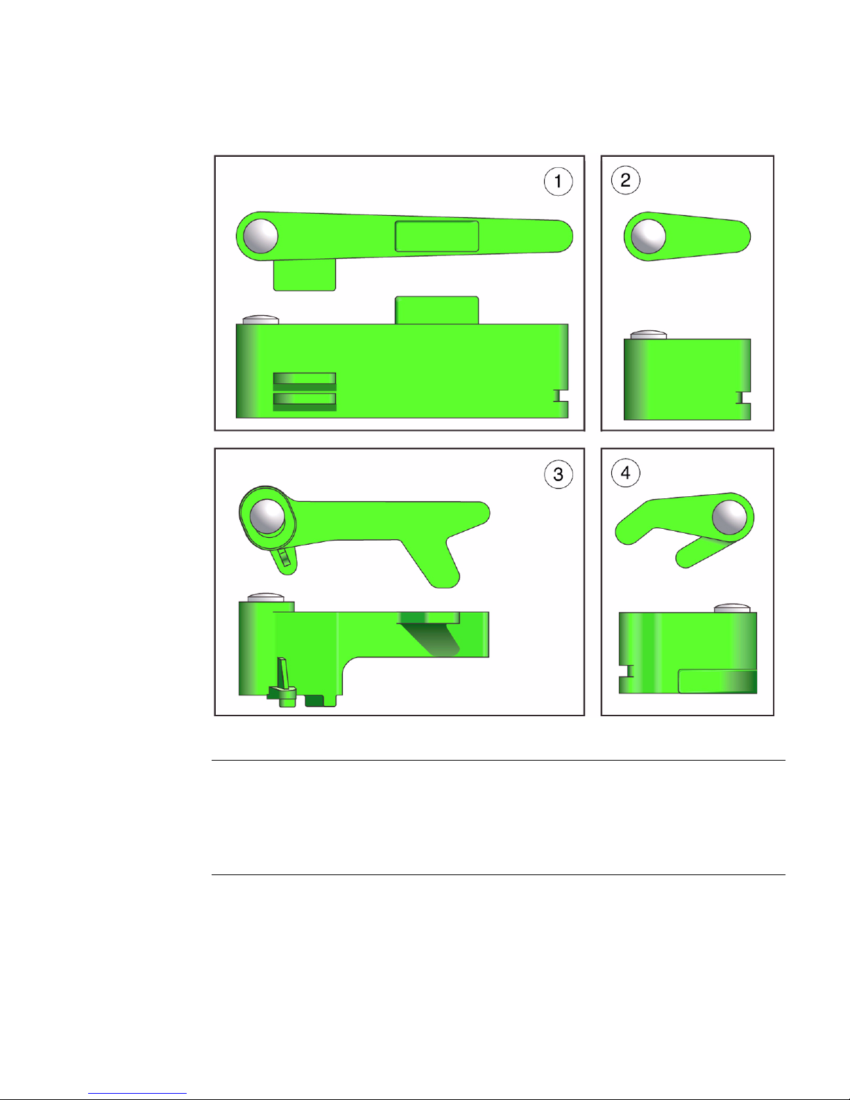
FIGURE 4-1 PCI Card Retainers
Figure Legend
1 Long retainer; mfg part number: 340747400038, 60mm long
2 Short, straight retainer; mfg part number: 340747400037, 18mm long
(Note: This retainer fits the same cards as the short, curved retainer [4].)
3 Low-profile retainer; mfg part number: 340764100068, 48mm long
4 Short, curved retainer; mfg part number: 340747400039, 24mm long
(Note: This retainer fits the same cards as the short, straight retainer [2].)
The following figure shows examples of how to use these retainers with differently
sized PCI cards.
Chapter 4 Replacing Motherboard Assembly Components 4-3

Note – The short, straight retainers and the short, curved retainers can be used
interchangeably to secure the same cards. The short, curved retainer provides more
support.
FIGURE 4-2 PCI Card Retainer Examples
Figure Legend
1 Half-length, standard-height card secured with two short retainers
2 Low-profile card secured with one long retainer
3 Low-profile card secured with one low-profile retainer
4 Full-length, standard-height card secured with two short retainers and the retainer on the air duct
4-4 Sun Netra T5220 Server Service Manual • January 2012

4.2.2 Replacing PCI-X 4 and PCIe 5 Cards
Note – The maximum power of any one PCI card is 25 watts. Only PCI-X slot 4 and
PCIe slot 5 accept long cards.
▼ To Remove the PCI-X 4 and PCIe 5 Cards
1. Prepare the server for PCI card removal. See Section 4.1, “Powering Off and
Powering On the Server” on page 4-1.
2. With the PCI mezzanine installed and cabled, identify which card is to be
removed.
3. Loosen the appropriate PCI card retainers and securing screws (
The screws are captive and cannot be completely removed from the PCI
mezzanine.
FIGURE 4-3).
Chapter 4 Replacing Motherboard Assembly Components 4-5

FIGURE 4-3 Upper PCI Card Retainers and Securing Screws
PCIe 5
PCI-X 4
PCI-X 3
4. Slide the card to the left and lift it out of the PCI mezzanine (FIGURE 4-4).
4-6 Sun Netra T5220 Server Service Manual • January 2012

FIGURE 4-4 Removing PCI-X 4 and PCIe 5 Cards From the PCI Mezzanine
Set the card aside on an antistatic mat.
5. Consider your next step:
■ If you are replacing the card, continue to “To Install PCI-X 4 and PCIe 5 Cards” on
page 7.
■ If you do not replace the card, install a filler panel.
6. Tighten the card securing screws.
7. Bring the server back online. See Section 4.1, “Powering Off and Powering On
the Server” on page 4-1.
▼ To Install PCI-X 4 and PCIe 5 Cards
1. Prepare the server for PCI card installation. See Section 4.1, “Powering Off and
Powering On the Server” on page 4-1.
2. With the PCI mezzanine installed and cabled, determine which slot to install
the card and loosen the appropriate card securing screws (
3. Remove the replacement card from its packaging and place it onto an antistatic
mat.
4. If a filler panel is installed, remove it by pulling the tab.
FIGURE 4-3).
Chapter 4 Replacing Motherboard Assembly Components 4-7

5. Lower the card into position on the PCI mezzanine, then slide it to the right to
seat it into the connector (
FIGURE 4-5).
You must secure the right side of the PCI card faceplate into the small slot on the
right side of the PCI card slot (facing the rear of the server) before installing the
PCI card.
FIGURE 4-5 Installing PCI-X 4 and PCIe 5 Cards in the PCI Mezzanine
6. Tighten the card securing screws and appropriate PCI retainers (FIGURE 4-3).
7. Bring the server back online. See Section 4.1, “Powering Off and Powering On
the Server” on page 4-1.
4.2.3 Replacing the PCI-X 3 Card
Note – The maximum power of any one PCI card is 25 watts. Only PCI-X slot 4 and
PCIe slot 5 accept long cards.
4-8 Sun Netra T5220 Server Service Manual • January 2012

▼ To Remove the PCI-X 3 Card
1. Prepare the server for PCI card removal. See Section 4.1, “Powering Off and
Powering On the Server” on page 4-1.
2. With the PCI mezzanine installed and cabled, identify which card is to be
removed.
3. Loosen the appropriate PCI card retainers and securing screws (
The screws are captive and cannot be completely removed from the PCI
mezzanine.
4. Slide the card to the left and lift it out of the PCI mezzanine (
FIGURE 4-6 Removing the PCI-X 3 Card From the PCI Mezzanine
FIGURE 4-4).
Set the card aside on an antistatic mat.
FIGURE 4-3).
5. Consider your next step:
■ If you are replacing the card, continue to “To Install the PCI-X 3 Card” on page 9.
■ If you do not replace the card, install a filler panel.
6. Tighten the card securing screws.
7. Bring the server back online. See Section 4.1, “Powering Off and Powering On
the Server” on page 4-1.
▼ To Install the PCI-X 3 Card
1. Prepare the server for PCI card installation. See Section 4.1, “Powering Off and
Powering On the Server” on page 4-1.
Chapter 4 Replacing Motherboard Assembly Components 4-9

2. With the PCI mezzanine installed and cabled, loosen the appropriate card
securing screws (
FIGURE 4-3).
3. Remove the replacement card from its packaging and place it onto an antistatic
mat.
4. If a filler panel is installed, remove it by pulling the tab (
FIGURE 4-7).
5. Lower the card into position on the PCI mezzanine, then slide it to the right to
seat it into the connector (
6. Tighten the appropriate card securing screws and PCI retainers (
FIGURE 4-7 Installing the PCI-X 3 Card in the PCI Mezzanine
FIGURE 4-7).
FIGURE 4-7).
7. Bring the server back online. See Section 4.1, “Powering Off and Powering On
the Server” on page 4-1.
4-10 Sun Netra T5220 Server Service Manual • January 2012

4.2.4 Replacing the Lower PCIe/XAUI Cards
Note – The maximum power of any one PCI card is 25 watts. PCIe/XAUI slots 0 and
1 are the only slots that support XAUI cards.
▼ To Remove the Lower PCIe/XAUI Cards
1. Prepare the server for card removal. See Section 4.1, “Powering Off and Powering
On the Server” on page 4-1.
2. Remove the PCI mezzanine and place it on an anti-static mat.
3. Loosen the appropriate card securing screws (
4. Lift the PCI riser assembly (with PCI card attached) from the PCI mezzanine
(
FIGURE 4-8).
5. If installed, remove the card securing screw on the right side of the PCI card
faceplate (
6. Remove the PCI card from the PCI riser assembly (
FIGURE 4-8).
FIGURE 4-8).
FIGURE 4-8).
Chapter 4 Replacing Motherboard Assembly Components 4-11

FIGURE 4-8 Removing Lower PCIe/XAUI Cards From the PCI Mezzanine
7. Set the card aside on an antistatic mat.
8. Consider your next step:
■ If you are replacing the PCIe card, continue to Section 4.2.5, “Installing the Lower
PCIe/XAUI Cards” on page 4-12.
■ If you do not replace the PCIe card, install a filler panel.
9. Bring the server back online. See Section 4.1, “Powering Off and Powering On
the Server” on page 4-1.
4.2.5 Installing the Lower PCIe/XAUI Cards
1. Prepare the server for PCI card installation. See Section 4.1, “Powering Off and
Powering On the Server” on page 4-1.
2. Remove the PCI mezzanine and place it on an anti-static mat.
4-12 Sun Netra T5220 Server Service Manual • January 2012
 Loading...